
ASGG18CETA-B - Séparateur FUJITSU - Free user manual and instructions
Find the device manual for free ASGG18CETA-B FUJITSU in PDF.

| Product Type | Split System Indoor Unit |
| Model Number | ASGG18CETA-B |
| Brand | Fujitsu |
| Refrigerant | R32 |
| Power Supply | 230 V, 1 Phase, 50 Hz (powered from outdoor unit) |
| Connection Cable Specification | 4-conductor, 1.5 mm² |
| Gas Pipe Size | 12.70 mm (1/2 in) with 0.8 mm thickness |
| Liquid Pipe Size | 6.35 mm (1/4 in) with 0.8 mm thickness |
| Pipe Connection Type | Flare connection |
| Maximum Remote Control Distance | 7 m |
| Custom Code Selection | A, B, C, D (for multi-unit operation) |
| Filter Sign Interval Setting | Standard 400 h, Long 1000 h, Short 200 h, or No indication |
| Auto Restart After Power Failure | Enabled by default |
| Room Temperature Sensor Calibration | Adjustable from -4.0 °C to +4.0 °C |
| External Input Control Modes | Operation/Stop or Forced Stop |
| Energy Saving Fan Control | Yes (intermittent low speed when outdoor unit off) |
| Error Code Display | Blinking lamps on indoor unit or wired remote controller display |
| Accessories Included | Remote controller, batteries, wall hook bracket, air cleaning filters, template, etc. |
| Installation Type | Wall-mounted, professional installation required |
| Safety Precautions | Flammable refrigerant (R32), must install in room ≥2.6 m² |
| Drain Hose | Included; must slope downward to prevent water leakage |
| Optional Parts Available | Wired remote controller, external I/O PCB, WLAN adapter, communication kit |
| Group Control Capability | Up to 16 indoor units with one remote controller |
| Test Run Activation | Via remote controller 'TEST RUN' button or indoor unit button (10s press) |
Frequently Asked Questions - ASGG18CETA-B FUJITSU
User questions about ASGG18CETA-B FUJITSU
0 question about this device. Answer the ones you know or ask your own.
Ask a new question about this device
Download the instructions for your Séparateur in PDF format for free! Find your manual ASGG18CETA-B - FUJITSU and take your electronic device back in hand. On this page are published all the documents necessary for the use of your device. ASGG18CETA-B by FUJITSU.
USER MANUAL ASGG18CETA-B FUJITSU
natural_image
Simple line drawing of a rectangular container or shelf with no text, numbers, or symbolsContents
- SAFETY PRECAUTIONS .... 1
1.1. Precautions for using R32 refrigerant 1
- PRODUCT SPECIFICATION 3
2.1. Installation tools 3
2.2. Accessories 4
2.3. Pipe requirement 4
2.4. Electrical requirement 4
2.5.Optional parts 4
- INSTALLATION WORK 4
3.1. Selecting an installation location 4
3.2. Removing and replacing parts 5
3.3. Pipe installation 6
3.4. Electrical wiring....8
3.5. Remote controller installation 8
- OPTIONAL INSTALLATION WORK 9
4.1. Optional kit installation....9
4.2. Group control 10
- FUNCTION SETTING....10
5.1. Function details ..... 11
-
TEST RUN 12
-
FINISHING 12
-
CUSTOMER GUIDANCE 12
-
ERROR CODES 12
1. SAFETY PRECAUTIONS
- Be sure to read this manual thoroughly before installation.
- The warnings and precautions indicated in this manual contain important information pertaining to your safety. Be sure to observe them.
- Hand this manual, together with the operating manual, to the customer. Request the customer to keep them on hand for future use, such as for relocating or repairing the unit.
WARNING
Indicates a potentially or imminently hazardous situation which, if not avoided, could result in death or serious injury.
CAUTION
Indicates a potentially hazardous situation that may result in minor or moderate injury or damage to property.
INSTALLATION MANUAL
[NO TEXT]
PART No. 9387082555-02
For authorized service personnel only.
WARNING
- The appliance shall be installed, operated and stored in a room with a floor area larger than 2.60m^2
- Installation of this product must be done by experienced service technicians or professional installers only in accordance with this manual. Installation by non-professional or improper installation of the product might cause serious accidents such as injury, water leakage, electric shock, or fire. If the product is installed in disregard of the instructions in this manual, it will void the manufacturer's warranty.
- Do not turn on the power until all work has been completed. Turning on the power before the work is completed can cause serious accidents such as electric shock or fire.
- If refrigerant leaks when you are working, ventilate the area. If the leaking refrigerant is exposed to a direct flame, it may produce a toxic gas.
• Installation must be performed in accordance with regulations, codes, or standards for electrical wiring and equipment in each country, region, or the installation place. - Do not use means to accelerate the defrosting process or to clean, other than those recommended by the manufacturer.
- This appliance is not intended for use by persons (including children) with reduced physical, sensory or mental capabilities, or lack of experience and knowledge, unless they have been given supervision or instruction concerning use of the appliance by a person responsible for their safety. Children should be supervised to ensure that they do not play with the appliance.
- To avoid danger of suffocation, keep the plastic bag or thin film used as the packaging material away from young children.
- The appliance shall be stored in a room without continuously operating ignition sources (for example: open flames, an operating gas appliance or an operating electric heater).
- Do not pierce or burn.
- Be aware that refrigerants may not contain an odour.
CAUTION
- Read carefully all safety information written in this manual before you install or use the air conditioner.
• Install the product by following local codes and regulations in force at the place of installation, and the instructions provided by the manufacturer. - This product is part of a set constituting an air conditioner. The product must not be installed alone or be installed with a device not authorized by the manufacturer.
- Always use a separate power supply line protected by a circuit breaker operating on all wires with a distance between contact of 3mm for this product.
- To protect the persons, ground (earth) the product correctly, and use the power cable combined with an Earth Leakage Circuit Breaker (ELCB).
- This product is not explosion proof, and therefore should not be installed in an explosive atmosphere.
- To avoid getting an electric shock, never touch the electrical components soon after the power supply has been turned off. After turning off the power, always wait 5 minutes or more before you touch the electrical components.
- This product contains no user-serviceable parts. Always consult experienced service technicians for repairing.
- When moving or relocating the air conditioner, consult experienced service technicians for disconnection and reinstallation of the product.
- Do not touch the aluminum fins of heat exchanger built-in the indoor or outdoor unit to avoid personal injury when you install or maintain the unit.
- Do not place any other electrical products or household belongings under the product. Condensation dripping from the product might get them wet, and may cause damage or malfunction to the property.
- Be careful not to scratch the air conditioner when handling it.
1.1. Precautions for using R32 refrigerant
The basic installation work procedures are the same as conventional refrigerant (R410A, R22) models.
However, pay careful attention to the following points:
Since the working pressure is 1.6 times higher than that of refrigerant R22 models, some of the piping and installation and service tools are special. (Refer to "2.1. Installation tools".)
Especially, when replacing a refrigerant R22 model with a new refrigerant R32 model, always replace the conventional piping and flare nuts with the R32 and R410A piping and flare nuts on the outdoor unit side.
For R32 and R410A, the same flare nut on the outdoor unit side and pipe can be used.
Models that use refrigerant R32 and R410A have a different charging port thread diameter to prevent erroneous charging with refrigerant R22 and for safety. Therefore, check beforehand. [The charging port thread diameter for R32 and R410A is 1/2-20 UNF.]
Be more careful than R22 so that foreign matter (oil, water, etc.) does not enter the piping. Also, when storing the piping, securely seal the opening by pinching, taping, etc. (Handling of R32 is similar to R410A.)
CAUTION
1-Installation (Space)
- That the installation of pipe-work shall be kept to a minimum.
- That pipe-work shall be protected from physical damage.
- The appliance shall not be installed in an unventilated space, if that space is smaller than 2.60 ~m^2
- That compliance with national gas regulations shall be observed.
- That mechanical connections shall be accessible for maintenance purposes.
- In cases that require mechanical ventilation, ventilation openings shall be kept clear of obstruction.
- When disposing of the product is used, be based on national regulations, properly processed.
2-Servicing
2-1 Service personnel
- Any person who is involved with working on or breaking into a refrigerant circuit should hold a current valid certificate from an industry-accredited assessment authority, which authorises their competence to handle refrigerants safely in accordance with an industry recognised assessment specification.
- Servicing shall only be performed as recommended by the equipment manufacturer. Maintenance and repair requiring the assistance of other skilled personnel shall be carried out under the supervision of the person competent in the use of flammable refrigerants.
• Servicing shall be performed only as recommended by the manufacturer.
2-2 Work
- Prior to beginning work on systems containing flammable refrigerants, safety checks are necessary to ensure that the risk of ignition is minimized. For repair to the refrigerating system, the precautions in 2-2 to 2-8 shall be complied with prior to conducting work on the system.
- Work shall be undertaken under a controlled procedure so as to minimize the risk of a flammable gas or vapour being present while the work is being performed.
- All maintenance staff and others working in the local area shall be instructed on the nature of work being carried out.
• Work in confined spaces shall be avoided.
• The area around the workspace shall be sectioned off. - Ensure that the conditions within the area have been made safe by control of flammable material.
2-3 Checking for presence of refrigerant
- The area shall be checked with an appropriate refrigerant detector prior to and during work, to ensure the technician is aware of potentially flammable atmospheres.
- Ensure that the leak detection equipment being used is suitable for use with flammable refrigerants, i.e. nonsparking, adequately sealed or intrinsically safe.
2-4 Presence of fire extinguisher
- If any hot work is to be conducted on the refrigeration equipment or any associated parts, appropriate fire extinguishing equipment shall be available at hand.
- Have a dry powder or CO_2 fire extinguisher adjacent to the charging area.
2-5 No ignition sources
- No person carrying out work in relation to a refrigeration system which involves exposing any pipe work that contains or has contained flammable refrigerant shall use any sources of ignition in such a manner that it may lead to the risk of fire or explosion.
- All possible ignition sources, including cigarette smoking, should be kept sufficiently far away from the site of installation, repairing, removing and disposal, during which flammable refrigerant can possibly be released to the surrounding space.
- Prior to work taking place, the area around the equipment is to be surveyed to make sure that there are no flammable hazards or ignition risks. "No Smoking" signs shall be displayed.
2-6 Ventilated area
- Ensure that the area is in the open or that it is adequately ventilated before breaking into the system or conducting any hot work.
- A degree of ventilation shall continue during the period that the work is carried out.
- The ventilation should safely disperse any released refrigerant and preferably expel it externally into the atmosphere.
2-7 Checks to the refrigeration equipment
- Where electrical components are being changed, they shall be fit for the purpose and to the correct specification.
- At all times the manufacturer's maintenance and service guidelines shall be followed.
- If in doubt consult the manufacturer's technical department for assistance.
- The following checks shall be applied to installations using flammable refrigerants.
- The charge size is in accordance with the room size within which the refrigerant containing parts are installed.
- The ventilation machinery and outlets are operating adequately and are not obstructed.
- If an indirect refrigerating circuit is being used, the secondary circuit shall be checked for the presence of refrigerant.
- Marking to the equipment continues to be visible and legible. Markings and signs that are illegible shall be corrected.
- Refrigeration pipe or components are installed in a position where they are unlikely to be exposed to any substance which may corrode refrigerant containing components, unless the components are constructed of materials which are inherently resistant to being corroded or are suitably protected against being so corroded.
CAUTION
2-8 Checks to electrical devices
- Repair and maintenance to electrical components shall include initial safety checks and component inspection procedures.
- If a fault exists that could compromise safety, then no electrical supply shall be connected to the circuit until it is satisfactorily dealt with.
- If the fault cannot be corrected immediately but it is necessary to continue operation, an adequate temporary solution shall be used.
- This shall be reported to the owner of the equipment so all parties are advised.
- Initial safety checks shall include.
- That capacitors are discharged: this shall be done in a safe manner to avoid possibility of sparking.
- That there no live electrical components and wiring are exposed while charging, recovering or purging the system.
- That there is continuity of earth bonding.
3-Repairs to sealed components
- During repairs to sealed components, all electrical supplies shall be disconnected from the equipment being worked upon prior to any removal of sealed covers, etc.
- If it is absolutely necessary to have an electrical supply to equipment during servicing, then a permanently operating form of leak detection shall be located at the most critical point to warn of a potentially hazardous situation.
- Particular attention shall be paid to the following to ensure that by working on electrical components, the casing is not altered in such a way that the level of protection is affected.
- This shall include damage to cables, excessive number of connections, terminals not made to original specification, damage to seals, incorrect fitting of glands, etc.
- Ensure that apparatus is mounted securely.
- Ensure that seals or sealing materials have not degraded such that they no longer serve the purpose of preventing the ingress of flammable atmospheres.
- Replacement parts shall be in accordance with the manufacturer's specifications.
NOTES: The use of silicon sealant may inhibit the effectiveness of some types of leak detection equipment. Intrinsically safe components do not have to be isolated prior to working on them.
4-Repair to intrinsically safe components
- Do not apply any permanent inductive or capacitance loads to the circuit without ensuring that this will not exceed the permissible voltage and current permitted for the equipment in use.
- Intrinsically safe components are the only types that can be worked on while live in the presence of a flammable atmosphere.
- The test apparatus shall be at the correct rating.
- Replace components only with parts specified by the manufacturer.
- Other parts may result in the ignition of refrigerant in the atmosphere from a leak.
5-Cabling
- Check that cabling will not be subject to wear, corrosion, excessive pressure, vibration, sharp edges or any other adverse environmental effects.
• The check shall also take into account the effects of aging or continual vibration from
sources such as compressors or fans.
6-Detection of flammable refrigerants
- Under no circumstances shall potential sources of ignition be used in the searching for or detection of refrigerant leaks.
- A halide torch (or any other detector using a naked flame) shall not be used.
7-Leak detection methods
- Electronic leak detectors shall be used to detect flammable refrigerants, but the sensitivity may not be adequate, or may need re-calibration. (Detection equipment shall be calibrated in a refrigerant-free area.)
- Ensure that the detector is not a potential source of ignition and is suitable for the refrigerant used.
- Leak detection equipment shall be set at a percentage of the LFL of the refrigerant and shall be calibrated to the refrigerant employed and the appropriate percentage of gas (25 % maximum) is confirmed.
- Leak detection fluids are suitable for use with most refrigerants but the use of detergents containing chlorine shall be avoided as the chlorine may react with the refrigerant and corrode the copper pipe-work.
- If a leak is suspected, all naked flames shall be removed/extinguished.
- If a leakage of refrigerant is found which requires brazing, all of the refrigerant shall be recovered from the system, or isolated (by means of shut off valves) in a part of the system remote from the leak.
Oxygen free nitrogen (OFN) shall then be purged through the system both before and during the brazing process.
CAUTION
8-Removal and evacuation
- When breaking into the refrigerant circuit to make repairs – or for any other purpose – conventional procedures shall be used. However, it is important that best practice is followed since flammability is a consideration.
The following procedure shall be adhered to:
- remove refrigerant
• purge the circuit with inert gas
- evacuate
• purge again with inert gas
- open the circuit by cutting or brazing
• The refrigerant charge shall be recovered into the correct recovery cylinders.
- The system shall be "flushed" with OFN to render the unit safe.
• This process may need to be repeated several times.
- Compressed air or oxygen shall not be used for this task.
- Flushing shall be achieved by breaking the vacuum in the system with OFN and continuing to fill until the working pressure is achieved, then venting to atmosphere, and finally pulling down to a vacuum.
• This process shall be repeated until no refrigerant is within the system.
- When the final OFN charge is used, the system shall be vented down to atmospheric pressure to enable work to take place.
- This operation is absolutely vital if brazing operations on the pipe work are to take place.
- Ensure that the outlet for the vacuum pump is not close to any ignition sources and there is ventilation available.
9-Charging procedures
- In addition to conventional charging procedures, the following requirements shall be followed.
- Ensure that contamination of different refrigerants does not occur when using charging equipment.
Hoses or lines shall be as short as possible to minimize the amount of refrigerant contained in them.
- Cylinders shall be kept upright.
- Ensure that the refrigeration system is earthed prior to charging the system with refrigerant.
- Label the system when charging is complete (if not already).
- Extreme care shall be taken not to overfill the refrigeration system.
- Prior to recharging the system it shall be pressure tested with OFN.
- The system shall be leak tested on completion of charging but prior to commissioning.
- A follow up leak test shall be carried out prior to leaving the site.
10-Decommissioning
- Before carrying out this procedure, it is essential that the technician is completely familiar with the equipment and all its details.
- It is recommended good practice that all refrigerants are recovered safely.
- Prior to the task being carried out, an oil and refrigerant sample shall be taken in case analysis is required prior to re-use of reclaimed refrigerant.
- It is essential that electrical power is available before the task is commenced.
a) Become familiar with the equipment and its operation.
b) Isolate system electrically.
c) Before attempting the procedure ensure that:
- mechanical handling equipment is available, if required, for handling refrigerant cylinders;
- all personal protective equipment is available and being used correctly;
- the recovery process is supervised at all times by a competent person;
- recovery equipment and cylinders conform to the appropriate standards.
d) Pump down refrigerant system, if possible.
e) If a vacuum is not possible, make a manifold so that refrigerant can be removed from various parts of the system.
f) Make sure that cylinder is situated on the scales before recovery takes place.
g) Start the recovery machine and operate in accordance with manufacturer's instructions.
h) Do not overfill cylinders. (No more than 80 % volume liquid charge).
i) Do not exceed the maximum working pressure of the cylinder, even temporarily.
j) When the cylinders have been filled correctly and the process completed, make sure that the cylinders and the equipment are removed from site promptly and all isolation valves on the equipment are closed off.
k) Recovered refrigerant shall not be charged into another refrigeration system unless it has been cleaned and checked.
11-Labelling
- Equipment shall be labelled stating that it has been de-commissioned and emptied of refrigerant.
• The label shall be dated and signed.
- Ensure that there are labels on the equipment stating the equipment contains flammable refrigerant.
CAUTION
12-Recovery
- When removing refrigerant from a system, either for servicing or decommissioning, it is recommended good practice that all refrigerants are removed safely.
- When transferring refrigerant into cylinders, ensure that only appropriate refrigerant recovery cylinders are employed.
- Ensure that the correct number of cylinders for holding the total system charge are available.
- All cylinders to be used are designated for the recovered refrigerant and labelled for that refrigerant (i.e. special cylinders for the recovery of refrigerant).
- Cylinders shall be complete with pressure relief valve and associated shut-off valves in good working order.
- Empty recovery cylinders are evacuated and, if possible, cooled before recovery occurs.
- The recovery equipment shall be in good working order with a set of instructions concerning the equipment that is at hand and shall be suitable for the recovery of flammable refrigerants.
- In addition, a set of calibrated weighing scales shall be available and in good working order.
- Hoses shall be complete with leak-free disconnect couplings and in good condition.
- Before using the recovery machine, check that it is in satisfactory working order, has been properly maintained and that any associated electrical components are sealed to prevent ignition in the event of a refrigerant release. Consult manufacturer if in doubt.
- The recovered refrigerant shall be returned to the refrigerant supplier in the correct recovery cylinder, and the relevant Waste Transfer Note arranged.
- Do not mix refrigerants in recovery units and especially not in cylinders.
- If compressors or compressor oils are to be removed, ensure that they have been evacuated to an acceptable level to make certain that flammable refrigerant does not remain within the lubricant.
- The evacuation process shall be carried out prior to returning the compressor to the suppliers.
- Only electric heating to the compressor body shall be employed to accelerate this process.
- When oil is drained from a system, it shall be carried out safely.
2. PRODUCT SPECIFICATION
2.1. Installation tools
| Tool name Change from R22 to R32 (R410A) | |
| Gauge manifold | Pressure is high and cannot be measured with a R22 gauge. To prevent erroneous mixing of other refrigerants, the diameter of each port has been changed.It is recommended to use gauge with seals -0.1 to 5.3 MPa (-1 to 53 bar) for high pressure.-0.1 to 3.8 MPa (-1 to 38 bar) for low pressure. |
| Charge hose | To increase pressure resistance, the hose material and base size were changed. (R32/R410A) |
| Vacuum pump | A conventional vacuum pump can be used by installing vacuum pump adapter.(Use of a vacuum pump with a series motor is prohibited.) |
| Gas leakage detector | Special gas leakage detector for HFC refrigerant R410A or R32. |
■ Copper pipes
It is necessary to use seamless copper pipes and it is desirable that the amount of residual oil is less than 40 mg/10 m. Do not use copper pipes having a collapsed, deformed or discolored portion (especially on the interior surface). Otherwise, the expansion value or capillary tube may become blocked with contaminants.
As an air conditioner using R32 (R410A) incurs pressure higher than when using R22, it is necessary to choose adequate materials.

WARNING
- Do not use the existing (for R22) piping and flare nuts.
If the existing materials are used, the pressure inside the refrigerant cycle will rise and cause failure, injury, etc. (Use the special R32/R410A materials.) - Use (refill or replace with) specified refrigerant (R32) only. Use of unspecified refrigerant can cause product malfunction, burst, or injury.
- Do not mix any gas or impurities except specified refrigerant (R32). Inflow of air or application of unspecified material makes the internal pressure of the refrigerant cycle too high, and may cause product malfunction, burst of piping, or injury.
- For installation purposes, be sure to use the parts supplied by the manufacturer or other prescribed parts. The use of non-prescribed parts can cause serious accidents such as the unit falling, water leakage, electric shock, or fire.
- Do not turn on the power until all work has been completed.

CAUTION
This manual describes how to install the indoor unit only. To install the outdoor unit or branch box, (if any), refer to the installation manual included in each product.
2.2. Accessories
The following installation accessories are supplied. Use them as required.
| Name and Shape | Q'ty | Name and Shape | Q'ty |
Operating manual | 1 | Tapping screws (large) | 8 |
Installation manual(This manual) | 1 | Tapping screws (small) | 2 |
| Remote controller[SWAL] | 1 | Battery | 2 |
| Remote controller holder[SWAL] | 1 | Wall hook bracket[CREA] | 2 |
Cloth tape | 1 | Air cleaning filters | 2 |
Filter holder | 2 | Template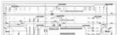 | 1 |
The following items are necessary to install this air conditioner. (The items are not included with the air conditioner and must be purchased separately.)
| Additional materials | |
| Connection pipe assembly Wall cap | |
| Connection cable (4-conductor) | Saddle |
| Wall pipe Drain hose | |
| Decorative tape Tapping screws | |
| Vinyl tape Putty | |
2.3. Pipe requirement

CAUTION
Refer to the installation manual for the outdoor unit for description of allowable pipe length and height difference.
| Model | Gas pipe size (thickness) [mm] | Liquid pipe size (thickness) [mm] |
| 18/24 | 12.70 (0.8) | 6.35 (0.8) |
| 30/36 | 15.88 (0.8) | 9.52 (0.8) |

CAUTION
- Wrap heat insulation around both gas pipe and liquid pipe.
No heat-insulation work or incorrect heat-insulation work may cause water leaks. - In a reverse cycle model, use heat insulation with heat resistance above 120 °C.
- If expected humidity of the installation location of refrigerant pipes is higher than 70% , wrap the heat insulation around the refrigerant pipes.
If the expected humidity is between 70 % and 80 %, use heat insulation that has a thickness of 15 mm or more.
If the expected humidity is higher than 80 %, use heat insulation that has a thickness of 20 mm or more. - The use of thinner heat insulation than specified above, may cause a condensation on the surface of the insulation.
- Use heat insulation with thermal conductivity of 0.045 W/(m·K) or less, at 20 °C.
2.4. Electrical requirement
The indoor unit is powered from the outdoor unit. Do not power indoor unit from separate power source.

WARNING
Standard for electrical wiring and equipment differs in each country or region. Before you start electrical working, confirm related regulations, codes, or standards.
| Cable | Conductor size [mm2] Type | Remarks | |
| Connection cable | 1.5 IS 694 | 3 cable + Ground (Earth), 1 ∅ 230 V | |
Cable Length: Limit voltage drop to less than 2%. Increase cable gauge if voltage drop is 2% or more.
2.5. Optional parts
Refer to each installation manual for the method of installing optional parts.
| Parts name Model No. Application | ||
| Wired remote controller (*1) | UTY-RNR*Z* | For air conditioner operation(2-wired type) |
| UTY-RLR * | ||
| Simple remote controller (*1) | UTY-RSR* | |
| UTY-RHR* | ||
| External input and output PCB(*2) | UTY-XCSXZ2 | For control input/output port |
| External connect kit (*2) UTY-XWZXZ5 | ||
| Communication kit UTY-TWRXZ2 For the installation of optional parts | ||
| WLAN adapter (*2) UTY-TFSXF3 For wireless LAN control | ||
*1: Optional Communication kit (UTY-TWRXZ2) is necessary for installation.
*2: The External input and output PCB and the WLAN adapter cannot be used simultaneously.
3. INSTALLATION WORK
3.1. Selecting an installation location
Decide the mounting position with the customer as follows:
(1) Install the indoor unit level on a strong wall which is not subject to vibration.
(2) The inlet and outlet ports should not be obstructed: the air should be able to blow all over the room.
(3) Install the unit a dedicated electrical branch circuit.
(4) Do not install the unit where it will be exposed to direct sunlight.
(5) Install the unit where connection to the outdoor unit is easy.
(6) Install the unit where the drain pipe can be easily installed
(7) Take servicing, etc. into consideration and leave the spaces. Also install the unit where the filter can be removed.
Correct initial installation location is important because it is difficult to move the unit after it is installed.

WARNING
Install the indoor unit where is capable to support the weight of the unit. Secure the unit firmly so that the unit does not topple or fall.

CAUTION
- Do not install the unit in the following areas:
- Area with high salt content, such as at the seaside. It will deteriorate metal parts, causing the parts to fail or the unit to leak water.
- Area filled with mineral oil or containing a large amount of splashed oil or steam, such as a kitchen. It will deteriorate plastic parts, causing the parts to fail or the unit to leak water.
- Area where is close to heat sources.
- Area that generates substances that adversely affect the equipment, such as sulfuric gas, chlorine gas, acid, or alkali. It will cause the copper pipes and brazed joints to corrode, which can cause refrigerant leakage.
- Area that can cause combustible gas to leak, contains suspended carbon fibers or flammable dust, or volatile in flammables such as paint thinner or gasoline.
- If gas leaks and settles around the unit, it can cause a fire.
Area where animals may urinate on the unit or ammonia may be generated.
- Do not use the unit for special purposes, such as storing food, raising animals, growing plants, or preserving precision devices or art objects. It can degrade the quality of the preserved or stored objects.
• Install the unit where drainage does not cause any trouble. - Install the indoor unit, outdoor unit, power supply cable, transmission cable, and remote control cable at least 1 m away from a television or radio receivers. The purpose of this is to prevent TV reception interference or radio noise.
(Even if they are installed more than 1 m apart, you could still receive noise under some signal conditions.)
- If children under 10 years old may approach the unit, take preventive measures so that they cannot reach the unit.
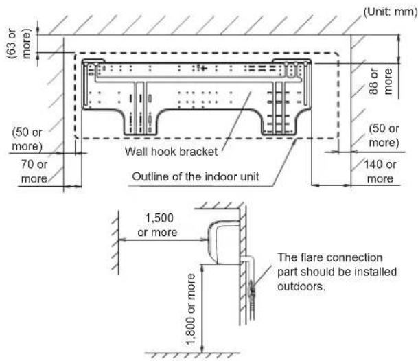
• Install the indoor unit on the wall where the height from the floor is more than 1.8 m.
3.1.1. Installation dimensions
Keep the distance between the wall hook bracket or indoor unit to the surrounding walls as indicated in the following figure.
3.2. Removing and replacing parts
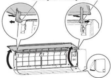
3.2.1. Intake grille removal and installation
■ Intake grille removal
(1) Open the intake grille.
(2) While pressing the left and right mounting shafts outward gently, pull the intake grille.
Mounting shaft Mounting shaft
■ Intake grille installation
(1) While holding the intake grille horizontal, set the left and right mounting shafts into the pillow blocks at the top of the front panel.
Insert the shaft until it snaps to latch each shaft properly.
Mounting shaft Mounting shaft
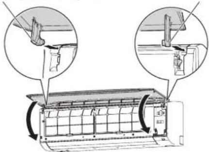
(2) Close the intake grille.
(3) Press 4 places on the intake grille to close it completely.
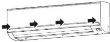
natural_image
Line drawing of a car air conditioner unit with airflow arrows indicating direction (no text or symbols)3.2.2. Front panel/control cover removal and installation
* In this description, the intake grille and wire cover already has been removed.
■ Front panel/control cover removal
(1) Remove intake grille. (Refer to "Intake grille removal".)
(2) Remove 4 caps.
(3) Remove wire cover. (2-screws)
(4) Remove 10 screws.
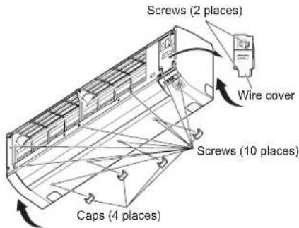
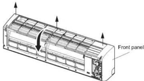
NOTES : When replacing the front panel, do not scratch or damage the louver.
(5) The front panel is pulled to the front, raising the upper surface, then the front panel is removed.
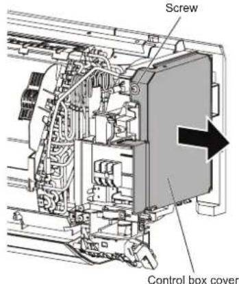
(6) Remove 1 screw, then remove the control box cover.
■ Front panel/control cover installation
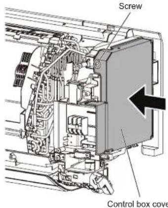
(1) Replace the control box cover and screw.
(2) First, fit the lower part of the front panel, and insert top and middle hooks. (3 top sides, 5 middles)
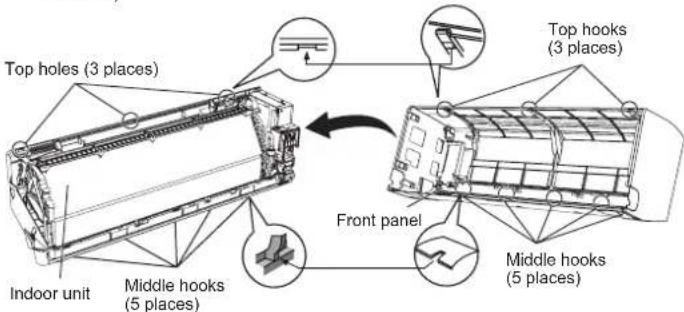
(3) Attach the 10 screws.
(4) Attach the wire cover. (2-screws)
(5) Attach the 4 caps.
(6) Attach the intake grille.
CAUTION
Please take caution when removing or installing the front panel. If the front panel falls, there is a risk of injury.
3.3. Pipe installation
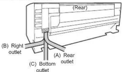
3.3.1. Indoor unit piping direction
The piping can be connected in the 3 directions indicated in the following.
When the piping is connected to direction (B) or (C), cut along the piping groove on the side of the front cover with a hacksaw.
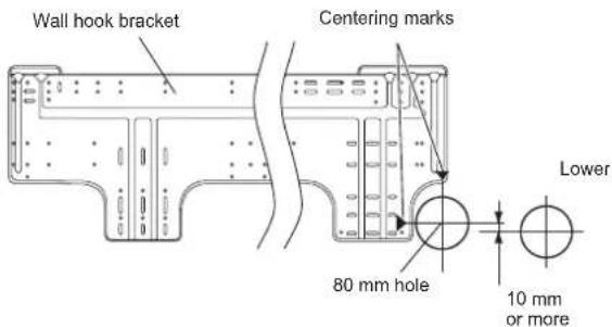
3.3.2. Cutting the hole in the wall for connecting the pipes
(1) Cut a 80 mm diameter hole in the wall at the position shown in the following.
(2) Cut the hole so that the outside end is lower (5 to 10 mm) than the inside end.
(3) Always align the center of the wall hole. If misaligned, water leakage will occur.
(4) Cut the wall pipe to match the wall thickness, stick it into the wall cap, fasten the cap with vinyl tape, and stick the pipe through the hole.
(5) Cut the hole a little lower so that drain water will flow freely.
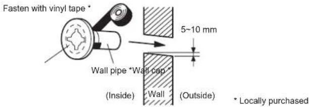
WARNING
Always use the wall pipe. If the wall pipe is not used, the cable that is connected between the indoor unit and the outdoor unit may touch metal, and cause an electric discharge.
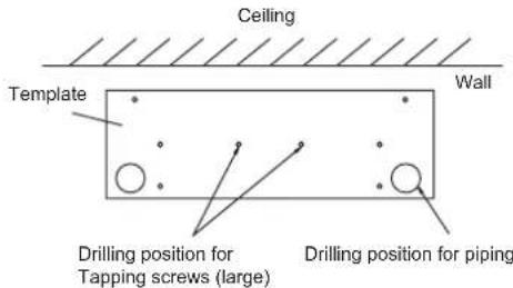
3.3.3. Indoor unit installation
- You can use the accessory template to help you install the indoor unit.
- The template helps you determine the appropriate locations for Tapping screws (large) and pipe opening (drain pipe and connection cable).
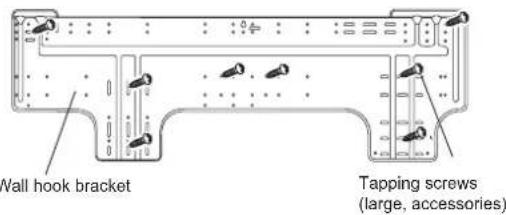
3.3.4. Installing the wall hook bracket
(1) Install the wall hook bracket so that it is correctly positioned horizontally and vertically. If the wall hook bracket is titled, water will drip to the floor.
(2) Install the wall hook bracket so that it is strong enough to support the weight of the unit.
- Fasten the wall hook bracket to the wall with 5 or more screws through the holes near the outer edge of the bracket.
- Check that there is no rattle at the wall hook bracket.
CAUTION
Install the wall-hook bracket both horizontally and vertically aligned. Misaligned installation may cause water leakage.
3.3.5. Forming the drain hose and pipe
CAUTION
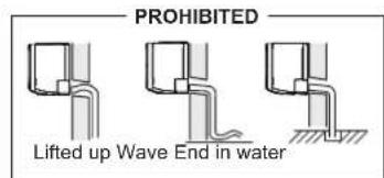
- Insert drain hose and drain cap securely. Drain should slope down to avoid water leakage.
- When inserting the drain hose, no other material than water should be applied. Application of other material than water will cause deterioration of the hose, and may cause water leakage.
• After you remove a drain hose, be sure to attach the drain cap. - When you secure the piping and drain hose with tape, arrange the drain hose so that it is at the bottom of the piping.
- For drain hose piping in low temperature environment, you need to apply freeze
protection to prevent a frozen drain hose. After cooling operation is performed in low temperature environment (when outdoor temperature under 0 °C), water in the drain hose could be frozen. Frozen drain water will block the water flow in the hose, and may cause water leakage at the indoor unit.
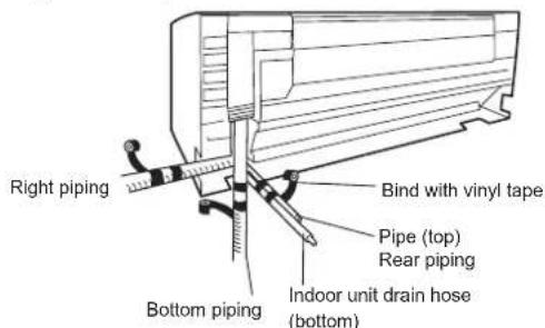
■ Rear piping, Right piping, Bottom piping
• Install the indoor unit piping in the direction of the wall hole and bind the drain hose and pipe together with vinyl tape.
• Install the piping so that the drain hose is at the bottom.
- Wrap the pipes of the indoor unit that are visible from the outside with decorative tape.
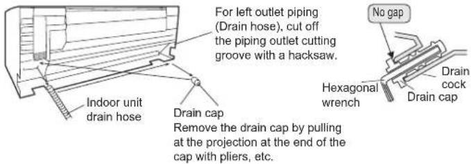
■ For Left rear piping (Drain hose), Left piping (Drain hose)
Interchange the drain cap and the drain hose.
■ Installing the drain cap
Use a hexagonal wrench 4 mm at opposite side to insert the drain cap, till the drain cap contacts the tip of the drain cock.
CAUTION
Insert the drain hose and drain cap into the drain port, making sure that it comes in contact with the back of the drain port, and then mount it. If the drain hose is not connected properly, leaking will occur.
■ Installing the indoor unit
- Hang the indoor unit from the hooks at the top of the wall hook bracket.
- Insert the spacer, etc. between the indoor unit and the wall hook bracket and separate the bottom of the indoor unit from the wall.
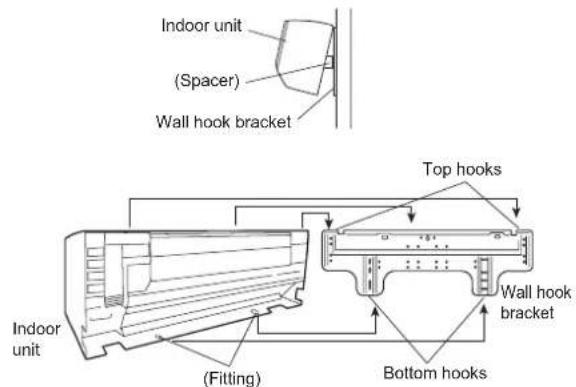
• After hooking the indoor unit to the top hook, hook the fittings of the indoor unit to the 2 bottom hooks while lowering the unit and pushing it against the wall.
3.3.6. Pipe connection
CAUTION
Tighten the flare nuts with a torque wrench using the specified tightening method. Otherwise, the flare nuts could break after a prolonged period, causing refrigerant to leak and generate hazardous gas if the refrigerant comes into contact with a flame.
Flaring
Use special pipe cutter and flare tool designed for R410A or R32 pipework.
(1) Cut the connection pipe to the necessary length with a pipe cutter.
(2) Hold the pipe downward so that cuttings will not enter the pipe and remove any burrs.
(3) Insert the flare nut (always use the flare nut attached to the indoor unit(s) and outdoor unit or branch box respectively) onto the pipe and perform the flare processing with a flare tool. Use the special R410A or R32 flare tool, or the conventional flare tool. Leakage of refrigerant may result if other flare nuts are used.
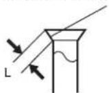
(4) Protect the pipes by pinching them or with tape to prevent dust, dirt, or water from entering the pipes.
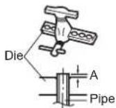
Check if [L] is flared uniformly and is not cracked or scratched.
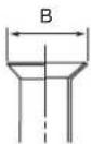
| Pipe outside diameter [mm (in.)] | Dimension A [mm] | Dimension B [mm] |
| Flare tool for R32, clutch type | ||
| 6.35 (1/4) | 0 to 0.5 | 9.1 |
| 9.52 (3/8) 13.2 | ||
| 12.70 (1/2) 16.6 | ||
| 15.88 (5/8) 19.7 | ||
| 19.05 (3/4) 24.0 |
When using conventional flare tools to flare R32 pipes, the dimension A should be approximately 0.5 mm more than indicated in the table (for flaring with R32 flare tools) to achieve the specified flaring. Use a thickness gauge to measure the dimension A.
Width across
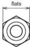
| Pipe outside diameter [mm (in.)] | Width across flats of Flare nut [mm] |
| 6.35 (1/4) 17 | |
| 9.52 (3/8) 22 | |
| 12.70 (1/2) 26 | |
| 15.88 (5/8) 29 | |
| 19.05 (3/4) 36 |
■ Bending pipes
CAUTION
• To prevent breaking of the pipe, avoid sharp bends.
- If the pipe is bent repeatedly at the same place, it will break.
• The pipes are shaped by your hands. Be careful not to collapse them.
- Bend R70 mm or more with a pipe bender.
- Do not bend the pipes in an angle more than 90^ .
- When pipes are repeatedly bend or stretched, the material will harden, making it difficult to bend or stretch them anymore.
- Do not bend or stretch the pipes more than 3 times.
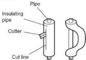
- When bending the pipe, do not bend it as is. The pipe will be collapsed. In this case, cut the insulating pipe with a sharp cutter as shown on the right, and bend it after exposing the pipe. After bending the pipe as you want, be sure to put the heat insulating pipe back on the pipe, and secure it with tape.
Flare connection
WARNING
The flare connection shall not be performed indoors.
CAUTION
- Be sure to install the pipe against the port on the indoor unit correctly. If the centering is improper, the flare nut cannot be tightened smoothly. If the flare nut is forced to turn, the threads will be damaged.
- Do not remove the flare nut from the indoor unit pipe until immediately before connecting the connection pipe.
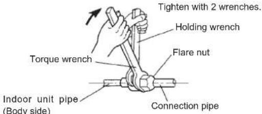
- Hold the torque wrench at its grip, keeping it in the right angle with the pipe, in order to tighten the flare nut correctly.
- Tighten the flare nuts with a torque wrench using the specified tightening method. Otherwise, the flare nuts could break after a prolonged period, causing refrigerant to leak and generate hazardous gas if the refrigerant comes into contact with a flame.
- Connect the piping so that the control box cover can easily be removed for servicing when necessary.
- In order to prevent water from leaking into the control box, make sure that the piping is well insulated.
When the flare nut is tightened properly by your hand, hold the body side coupling with a wrench, then tighten with a torque wrench. (Refer to the following table for the flare nut tightening torques.)
| Flare nut [mm (in.)] Tightening torque [N·m (kgf·cm)] |
| 6.35 (1/4) dia. 16 to 1 12 (160 to 180) |
| 9.52 (3/8) dia. 32 to 42 (320 to 420) |
| 12.70 (1/2) dia. 49 to 61 (490 to 610) |
| 15.88 (5/8) dia. 63 to 75 (630 to 750) |
| 19.05 (3/4) dia. 90 to 110 (900 to 1,100) |
Do not remove the cap from the connection pipe before connecting the pipe.
3.4. Electrical wiring

WARNING
- Before connecting the wires, make sure the power supply is OFF.
• Every wire must be connected firmly. - No wire should be allowed to touch refrigerant tubing, the compressor, or any moving part.
- Loose wiring may cause the terminal to overheat or result in unit malfunction. A fire hazard may also exist. Therefore, be sure all wiring is tightly connected.
- Connect wires to the matching numbers of terminals.

CAUTION
Be careful not to generate a spark as follows for using a flammable refrigerant.
- Do not remove the fuse while the power is on.
- Do not disconnect the wiring while the power is on.
- It is recommended to position the outlet connection in a high position. Place the cords so that they do not get tangled.
3.4.1. Wiring system diagram
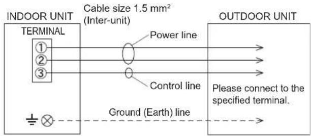
3.4.2. Indoor unit wiring
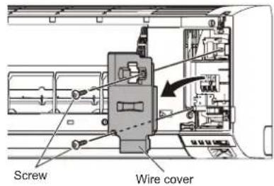
(1) Open the intake grille. Remove the tapping screw for the wire cover and remove the wire cover.
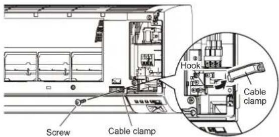
(2) Remove the tapping screw and while minding the cable clamp hook, remove the cable clamp.
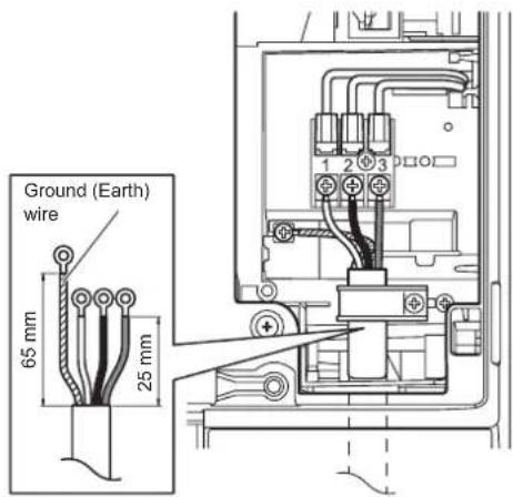
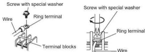
(3) Use the wire with ring terminals to connect to the terminal block.
3.4.3. How to connect wiring to the terminals
■ Caution when wiring cable
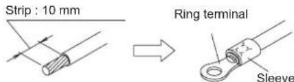
To strip off the insulation of a lead wire, always use a special tool such as a wire stripper. If there is no special tool, carefully strip off the insulation by using a knife or other utensil.
(1) Use ring terminals with insulating sleeves as shown in the figure to connect to the terminal block.
(2) Securely clamp the ring terminals to the wires by using an appropriate tool so that the wires do not come loose.
(3) Connect specified wires securely, and fasten them so that there is no stress applied on the terminals.
(4) Use a screwdriver with an appropriate bit size to tighten the terminal screws. Using of screwdriver with inappropriate bit size will damage the screw heads, and the screws will not be tightened properly.
(5) Do not overlighten the terminal screws. Otherwise, the screws may break.
(6) Refer to the table for the terminal screw tightening torques.
Tightening torque [N·m (kgf·cm)]
M4 screw 1.2 to 1.8 (12 to 18)
CAUTION
- Match the terminal block numbers and connection cable colors with those of the outdoor unit. Incorrect wiring may cause a fire.
- Connect the connection cables firmly to the terminal block. Imperfect installation may cause a fire.
- When fixing the connection cable with the cable clamp, always fasten the cable at the plastic jacket portion, but not at the insulator portion. If the insulator is chafed, electric leakage may occur.
• Always connect the ground (earth) wire. Improper earthing (grounding) work can cause electric shocks. - Do not use the ground (earth) screw for the indoor unit to the outdoor unit unless it is specified.
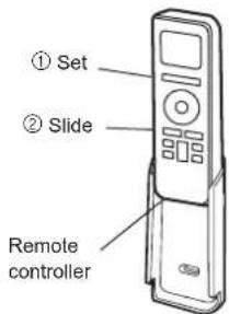
3.5. Remote controller installation
Check that the indoor unit correctly receives the signal from the remote controller, then install the remote controller holder.
CAUTION
Do not install the remote controller holder in the following conditions:
• Any places exposed in direct sunlight
- Positions affected by the heat from a stove or heater
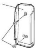
3.5.1. Remote controller holder installation
- Install the remote controller a maximum distance of 7 m from the remote control signal receiver. After installing the remote controller, check that it operates correctly.
- Install the remote controller holder to a wall, pillar, etc. with the tapping screw.
Remote controller holder fixing
Remote controller mounting
Remote controller holder
Tapping screw (small)
3.5.2. Remote controller custom setting
When 2 or more air conditioners are installed in a room and the remote controller is operating an air conditioner other than the one you wish to set, change the custom code of the remote controller to operate only the air conditioner you wish to set (4 selections possible).
- Confirm the setting of the remote controller custom code and the function setting. If these do not match, the remote controller cannot be used to operate for the air conditioner.
Selecting the Remote Controller Custom Code
Use the following steps to select the custom code of the remote controller. (Note that the air conditioner cannot receive a signal if the air conditioner has not been set for the custom code.)
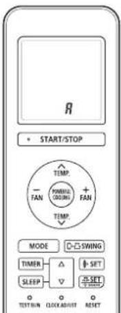
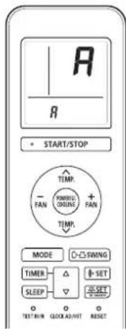
(1) Press the START/STOP button until only the clock is displayed on the remote controller display.
(2) Press the MODE button for at least 5 seconds to display the current custom code (initially set to A).
(3) Press SET TEMP. (∧) ( ) buttons to change the custom code between A→B→C→D. Match the code on the display to the air conditioner custom code.
(4) Press the MODE button again to return to the clock display. The custom code will be changed.
If no buttons are pressed within 30 seconds after the custom code is displayed, the system returns to the original clock display. In this case, start again from step 1.
The air conditioner custom code is set to A prior to shipment.
The remote controller resets to custom code A when the batteries in the remote controller are replaced. If you use a custom code other than custom code A, reset the custom code after replacing the batteries.
If you do not know the air conditioner custom code setting, try each of the custom codes (A → B → C → D) until you find the code which operates the air conditioner.
4. OPTIONAL INSTALLATION WORK
NOTES :
^* : The External input and output PCB and the WLAN adapter cannot be used simultaneously.
4.1. Optional kit installation
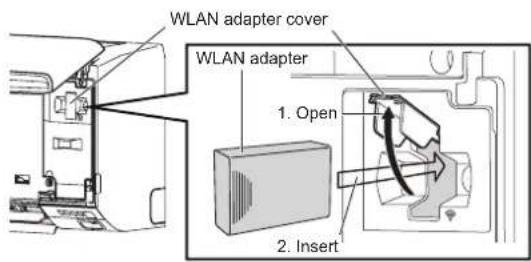
4.1.1. Installing the WLAN adapter
- For installing the WLAN adapter, refer to the operating manual.
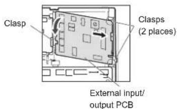
4.1.2. Installing the External input/output PCB
(1) Remove the Intake grille, front panel, and control cover. Refer to "3.2. Removing and replacing parts".
(2) Insert the PCB to the clasps (2 places). Push the PCB down until the clasp on the left is set.
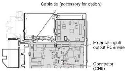
(3) Disconnect the WLAN adapter wire (CN6), then replace it with the wire for External input/output PCB.
(4) Hook the WLAN adapter wire to the control box. Fix it with a cable tie.
(5) For the setting of rotary switch and DIP switch, refer to the installation manual of optional parts.
NOTES: If the rotary switch on the "External input and output PCB" is set to "1", function number "46" will operate.
(6) Replace the control cover, front panel, and Intake grille.
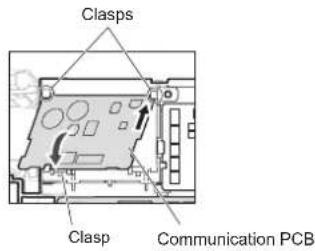
4.1.3. Installing the communication kit
(1) Remove the Intake grille, front panel, and control cover. Refer to "3.2. Removing and replacing parts".
(2) Insert the PCB to the clasps (2 places). Push the PCB down until the clasp on the bottom is set.
(3) Attach the terminal board to the indoor unit with 1 screw (accessory for option).
(4) Connect the connector of wire with EMI core to the communication PCB, then fix it with the cable tie (accessory for option).
(5) Connect the communication kit and main PCB.
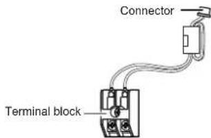
(6) Connect the wired remote controller cable to the terminal board as shown in the figure.
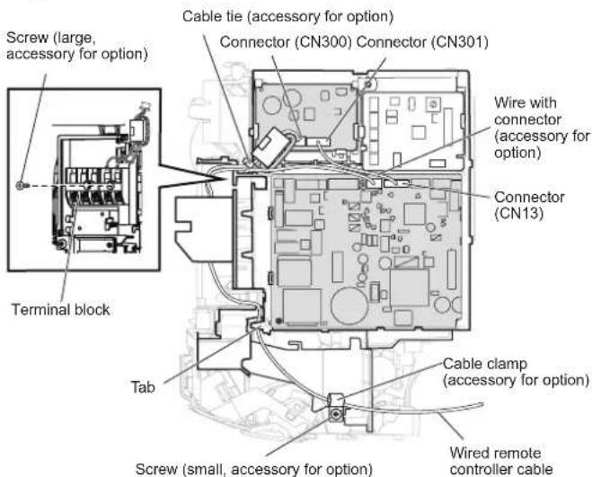
(7) Replace the control cover, front panel, and Intake grille.
4.2. Group control
4.2.1. Group control system
A number of indoor units can be operated at the same time using a single remote controller. *When different types of indoor units (such as wall mounted type and cassette type, cassette type and duct type, or other combinations) are connected using group control system, some functions may no longer be available.
(1) Connect up to 16 indoor units in a system.
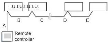
flowchart
graph TD
    A["Remote controller"] -->|A| B["I.U.I.U."]
    B -->|B| C["C"]
    C -->|C| D["D"]
    D -->|D| E["E"]
    E --> F[" "]
A, B, C, D, E : Remote controller cable. A+B+C+D+E ≤ 500 m.
Example of wiring method
Indoor unit 1 Indoor unit 2 Indoor unit 3 Indoor unit 4
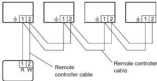
Remote controller
(2) Set the R.C. address (Function setting)
- Addresses will be automatically set when initially starting up this unit. In such a case, do not change the remote controller address for the indoor unit, and keep it at the initial setting of (00).
- Only set addresses manually when using different numbers for addresses.
Set the R.C. address of each indoor unit using the function setting. (Refer to "Remote controller address setting").
Also set the R.C. address for the remote controller. For details, please refer to the remote controller installation manual.
* In manual setting, connect up to 15 indoor units in a system.
Example
Example of wiring method
Indoor unit 1 Indoor unit 2 Indoor unit 3 Indoor unit 4
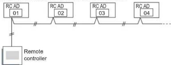
flowchart
graph TD
    A["RC AD 01"] --> B["Remote controller"]
    C["RC AD 02"] --> B
    D["RC AD 03"] --> B
    E["RC AD 04"] --> B
    B --> F["..."]
4.2.2. Remote controller address setting
(♦... Factory setting)
| Function Number | Setting Value | Setting Description |
| 00 | 00 | (For automatic setting) |
| 01 | Unit no. 1 | |
| 02 ~ 13 | Unit no. 2 ~ Unit no. 13 | |
| 14 | Unit no. 14 | |
| 15 | Unit no. 15 |
* Do not use the same setting value.
* After completing the Function Setting, be sure to disconnect the power supply and then reconnect it.
5. FUNCTION SETTING
Perform the Function setting according to the installation conditions using the remote controller.

- Confirm whether the wiring work for outdoor unit has been finished.
-
Confirm that the cover for the electrical enclosure on the outdoor unit is in place.
-
This procedure changes to the function settings used to control the indoor unit according to the installation conditions. Incorrect settings can cause the indoor unit to malfunction.
- After the power is turned on, perform the "FUNCTION SETTING" according to the installation conditions using the remote controller.
- The settings may be selected between the following two: Function Number and Setting Value.
- Settings will not be changed if invalid numbers or setting values are selected.
- Refer to the installation manual enclosed with the remote controller when the wired remote controller (option) is used.
Entering the Function Setting Mode
While pressing the POWERFUL COOLING button and MODE button simultaneously, press the RESET button to enter the function setting mode.
STEP 1
Selecting the Remote Controller Custom Code
Use the following steps to select the custom code of the remote controller. (Note that the air conditioner cannot receive a signal if the air conditioner has not been set for the custom code.) The custom codes that are set through this process are applicable only during the FUNCTION SETTING process. For details on how to set the custom codes through the normal process, refer to "Remote controller custom setting".
(1) Press TEMP. (∧) (√) buttons to change the custom code between A→B→C→D. Match the code on the display to the air conditioner custom code (initially set to A). (If the custom code does not need to be selected, press the MODE button and proceed to STEP 2.)
(2) Press the START/STOP button and check that the indoor unit can receive signals at the displayed custom code.
(3) Press the MODE button to accept the custom code, and proceed to STEP 2.
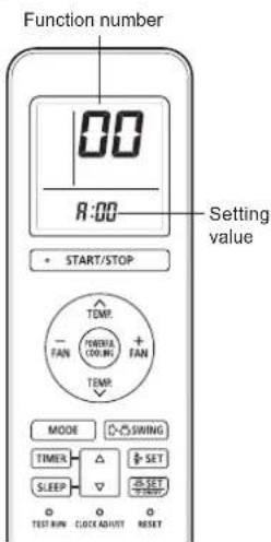
STEP 2
Selecting the Function Number and Setting Value
(1) Press the TEMP. (∧) (∨) buttons to select the function number. (Press the FAN (-) button to switch between the left and right digits.)
(2) Press the FAN (+) button to proceed to setting the value. (Press the FAN (+) button again to return to the function number selection.)
(3) Press the TEMP. (∧) (∨) buttons to select the setting value. (Press the FAN (-) button to switch between the left and right digits.)
(4) Press the START/STOP button, then the POWERFUL COOLING button, in order to fix the settings.
(5) Press the RESET button to end the function setting mode.
(6) After completing the FUNCTION SETTING, be sure to turn off the power and turn it on again.

After disconnecting the power supply, wait 30 seconds or more before reconnecting it. The Function Setting will not become active unless the power supply is disconnected and then reconnected.
5.1. Function details
Filter sign
Select appropriate intervals for displaying the filter sign on the indoor unit according to the estimated amount of dust in the air of the room.
If the indication is not required, select "No indication" (03).
(♦... Factory setting)
| Function number | Setting value | Setting description |
| 11 | 00 Standard (400 hours) | |
| 01 Long interval (1000 hours) | ||
| 02 Short interval (200 hours) | ||
| 03 No indication ♦ | ||
■ Room temperature control for indoor unit sensor
Depending on the installed environment, correction of the room temperature sensor may be required.
Select the appropriate control setting according to the installed environment.
The temperature correction values show the difference from the "Standard setting" (00) (manufacturer's recommended value).
(♦... Factory setting)
| Function number | Setting value | Setting description |
| 30(For cooling) | 00 Standard setting ◆ | |
| 01 No correction 0.0 °C (0 °F) | ||
| 02 -0.5 °C (-1 °F) | More Cooling | |
| 03 -1.0 °C (-2 °F) | ||
| 04 -1.5 °C (-3 °F) | ||
| 05 -2.0 °C (-4 °F) | ||
| 06 -2.5 °C (-5 °F) | ||
| 07 -3.0 °C (-6 °F) | ||
| 08 -3.5 °C (-7 °F) | ||
| 09 -4.0 °C (-8 °F) | ||
| 10 +0.5 °C (+1 °F) | Less Cooling | |
| 11 | +1.0 °C (+2 °F) | |
| 12 +1.5 °C (+3 °F) | ||
| 13 +2.0 °C (+4 °F) | ||
| 14 +2.5 °C (+5 °F) | ||
| 15 +3.0 °C (+6 °F) | ||
| 16 +3.5 °C (+7 °F) | ||
| 17 +4.0 °C (+8 °F) | ||
■ Room temperature control for wired remote controller sensor
Depending on the installed environment, correction of the wire remote temperature sensor may be required.
Select the appropriate control setting according to the installed environment.
To change this setting, set Function 42 to "Both" (01).
Ensure that the Thermo Sensor icon is displayed on the remote controller screen.
(♦... Factory setting)
| Function number | Setting value | Setting description |
| 35(For cooling) | 00 | No correction ◆ |
| 01 No correction 0.0 °C (0 °F) | ||
| 02 -0.5 °C (-1 °F) | ||
| 03 -1.0 °C (-2 °F) | ||
| 04 -1.5 °C (-3 °F) | ||
| 05 -2.0 °C (-4 °F) | ||
| 06 -2.5 °C (-5 °F) | ||
| 07 -3.0 °C (-6 °F) | ||
| 08 -3.5 °C (-7 °F) | ||
| 09 -4.0 °C (-8 °F) | ||
| 10 +0.5 °C (+1 °F) | ||
| 11 | +1.0 °C (+2 °F) | |
| 12 +1.5 °C (+3 °F) | ||
| 13 +2.0 °C (+4 °F) | ||
| 14 +2.5 °C (+5 °F) | ||
| 15 +3.0 °C (+6 °F) | ||
| 16 +3.5 °C (+7 °F) | ||
| 17 +4.0 °C (+8 °F) | ||
■ Auto restart
Enable or disable automatic restart after a power interruption.
(♦... Factory setting)
| Function number | Setting value | Setting description |
| 40 | 00 | Enable ◆ |
| 01 | Disable |
* Auto restart is an emergency function such as for power outage etc. Do not attempt to use this function in normal operation. Be sure to operate the unit by remote controller or external device.
■ Room temperature sensor switching
(Only for wired remote controller)
When using the wired remote controller temperature sensor, change the setting to "Both" (01).
(♦... Factory setting)
| Function number | Setting value | Setting description |
| 42 | 00 | Indoor unit |
| 01 | Both |
00: Sensor on the indoor unit is active.
01: Sensors on both indoor unit and wired remote controller are active.
* Remote controller sensor must be turned on by using the remote controller
■ Remote controller custom code
(Only for wireless remote controller)
The indoor unit custom code can be changed. Select the appropriate custom code.
(♦... Factory setting)
| Function number | Setting value | Setting description |
| 44 | 00 | A |
| 01 | B | |
| 02 | C | |
| 03 | D |
■ External input control
"Operation/Stop" mode or "Forced stop" mode can be selected.
(♦... Factory setting)
| Function number | Setting value | Setting description |
| 46 | 00 | Operation/Stop mode 1 |
| 01 | (Setting prohibited) | |
| 02 | Forced stop mode | |
| 03 | Operation/Stop mode 2 |
■ Room temperature sensor switching (Aux.)
To use the temperature sensor on the wired remote controller only, change the setting to "Wired remote controller" (01). This function will only work if the function setting 42 is set at "Both" (01)
(♦... Factory setting)
| Function number | Setting value | Setting description |
| 48 | 00 | Both ♦ |
| 01 | Wired remote controller |
■ Indoor unit fan control for energy saving for cooling
Enables or disables the power-saving function by controlling the indoor unit fan rotation when the outdoor unit is stopped during cooling operation.
(♦... Factory setting)
| Function number | Setting value | Setting description |
| 49 | 00 | Disable |
| 01 | Enable |
00: When the outdoor unit is stopped, the indoor unit fan operates continuously following the setting on the remote controller.
01: When the outdoor unit is stopped, the indoor unit fan operates intermittently at a very low speed.
■ Switching functions for external output terminal
Functions of the external output terminal can be switched.
(♦... Factory setting)
| Function number | Setting value | Setting description |
| 60 | 00 | Operation status |
| 01 to 08 (Setting prohibited) | ||
| 09 | Error status | |
| 10 | Indoor unit fan operation status | |
| 11 | (Setting prohibited) | |
Setting record
Record any changes to the settings in the following table.
| No. Setting description Setting value | ||
| 11 Filter sign | ||
| 30 Room temperature control for indoor unit sensor | ||
| 35 | Room temperature control for wired remote controller sensor | |
| 40 Auto restart | ||
| 42 Room temperature sensor switching | ||
| 44 Remote controller custom code | ||
| 46 External input control | ||
| 48 Room temperature sensor switching (Aux.) | ||
| 49 Indoor unit fan control for energy saving for cooling | ||
| 60 Switching functions for external output terminal | ||
After completing the Function Setting, be sure to disconnect the power supply and then reconnect it.
6. TEST RUN
Check items
(1) Is operation of each button on the remote control unit normal?
(2) Does each lamp light normally?
(3) Do air flow direction louvers operate normally?
(4) Is the drain normal?
(5) Do not have an abnormal noise and vibration during operation?
- Do not operate the air conditioner in test run for a long time.
■ Operation method
Before starting the test run, wait for 1 minute after connecting the power supply.
By the wireless remote controller
- To start the test run, press [START/STOP( ⏻/I)], [TEST RUN] on the remote controller by using the tip of a ballpoint pen or other small object.
By the indoor unit - To start the test run, keep on pressing the indoor unit button for more than 10 seconds.
- To end test operation, press the remote controller [START/STOP( ◎/I)]. (When the air conditioner is running by pressing [TEST RUN], the "OPERATION" Lamp and "TIMER" Lamp will simultaneously flash slowly.)
7. FINISHING
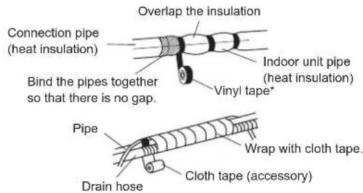
(1) Insulate between pipes.
• Insulate suction and discharge pipes separately.
- For rear, right, and bottom piping, overlap the connection pipe heat insulation and indoor unit pipe heat insulation and bind them with vinyl tape so that there is no g
(2) Temporarily fasten the connection cable along the connection pipe with vinyl tape. (Wrap to about 1/3 the width of the tape from the bottom of the pipe so that water does not enter.)
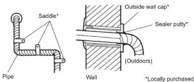
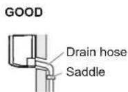
(3) Fasten the connection pipe to the outside wall with a saddle, etc.
(4) Fill the gap between the outside wall pipe hole and the pipe with sealer so that rain water and wind cannot blow in.
(5) Fasten the drain hose to the outside wall, etc.
(6) Check the drainage.
(7) Open the intake grille of the indoor unit. Set an air cleaning filter (accessories) to each filter folder (accessories) and attach to the air filter. For details of how to assemble the air filter, please refer to the operating manual.
8. CUSTOMER GUIDANCE
Explain the following to the customer in accordance with the operating manual:
(1) Starting and stopping method, operation switching, temperature adjustment, timer, airflow switching, and other remote control unit operations.
(2) Air filter removal and cleaning, and how to use the air louvers.
(3) Give the operating manual to the customer.
9. ERROR CODES
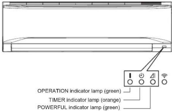
If you use a wireless remote controller, the lamp on the photo detector unit will output error codes by way of blinking patterns. If you use a wired remote controller, error codes will appear on the remote control display. Refer to the lamp blinking patterns and error codes in the table. An error display is displayed only during operation.
The error code contains errors irrelevant to this product as well.
| Error display | Error code | Description | ||
| OPERATION lamp (green) | TIMER lamp (orange) | POWERFUL lamp (green) | ||
| ●(1) | ●(1) | ◇ | 11 | Serial communication error |
| ●(1) | ●(2) | ◇ | 12 | Wired remote controller communication errorServer room control communication error |
| ●(1) | ●(5) | ◇ | 15 | Check run unfinished Automatic airflow adjustment error |
| ●(1) | ●(6) | ◇ | 16 | Peripheral unit transmission PCB connection error |
| ●(1) | ●(8) | ◇ | 18 | External communication error |
| ●(2) | ●(1) | ◇ | 21 | Unit number or Refrigerant circuit address setting error [simultaneous Multi] |
| ●(2) | ●(2) | ◇ | 22 | Indoor unit capacity error |
| ●(2) | ●(3) | ◇ | 23 | Combination error |
| ●(2) | ●(4) | ◇ | 24 | Connection unit number error (indoor secondary unit) [simultaneous Multi]Connection unit number error (indoor unit or branch unit) [flexible Multi] |
| ●(2) | ●(6) | ◇ | 26 | Indoor unit address setting error |
| ●(2) | ●(7) | ◇ | 27 | Primary unit, secondary unit setup error [simultaneous Multi] |
| ●(2) | ●(9) | ◇ | 29 | Connection unit number error in wired remote controller system |
| ●(3) | ●(1) | ◇ | 31 | Power supply interruption error |
| ●(3) | ●(2) | ◇ | 32 | Indoor unit PCB model information error |
| ●(3) | ●(3) | ◇ | 33 | Indoor unit motor electricity consumption detection error |
| ●(3) | ●(5) | ◇ | 35 | Manual auto switch error |
| ●(3) | ●(9) | ◇ | 39 | Indoor unit power supply error for fan motor |
| ●(3) | ●(10) | ◇ | 39 | Indoor unit communication circuit (wired remote controller) error |
| ●(4) | ●(1) | ◇ | 41 | Room temp. sensor error |
| ●(4) | ●(2) | ◇ | 42 | Indoor unit heat ex. middle temp. sensor error |
| ●(4) | ●(4) | ◇ | 44 | Human sensor error |
| ●(5) | ●(1) | ◇ | 51 | Indoor unit fan motor error |
| ●(5) | ●(3) | ◇ | 53 | Drain pump error |
| ●(5) | ●(4) | ◇ | 54 | Electric air cleaner reverse VDD error |
| ●(5) | ●(5) | ◇ | 55 | Filter set error |
| ●(5) | ●(7) | ◇ | 57 | Damper error |
| ●(5) | ●(8) | ◇ | 58 | Intake grille error |
| ●(5) | ●(9) | ◇ | 59 | Indoor unit fan motor 2 error (Left side fan) |
| ●(5) | ●(10) | ◇ | 5A | Indoor unit fan motor 3 error (Right side fan) |
| ●(5) | ●(15) | ◇ | 5U | Indoor unit error |
| ●(6) | ●(1) | ◇ | 61 | Outdoor unit reverse/missing phase and wiring error |
| ●(6) | ●(2) | ◇ | 62 | Outdoor unit main PCB model information error or communication error |
| ●(6) | ●(3) | ◇ | 63 | Inverter error |
| ●(6) | ●(4) | ◇ | 64 | Active filter error, PFC circuit error |
| ●(6) | ●(5) | ◇ | 65 | Trip terminal L error |
| ●(6) | ●(8) | ◇ | 68 | Outdoor unit rush current limiting resister temp. rise error |
| ●(6) | ●(10) | ◇ | 6A | Display PCB microcomputers communication error |
| ●(7) | ●(1) | ◇ | 71 | Discharge temp. sensor error |
| ●(7) | ●(2) | ◇ | 72 | Compressor temp. sensor error |
| ●(7) | ●(3) | ◇ | 73 | Outdoor unit Heat Ex. liquid temp. sensor error |
| ●(7) | ●(4) | ◇ | 74 | Outdoor temp. sensor error |
| ●(7) | ●(5) | ◇ | 75 | Suction Gas temp. sensor error |
| ●(7) | ●(6) | ◇ | 76 | • 2-way valve temp. sensor error• 3-way valve temp. sensor error |
| ●(7) | ●(7) | ◇ | 77 | Heat sink temp. sensor error |
| ●(8) | ●(2) | ◇ | 82 | • Sub-cool Heat Ex. gas inlet temp. sensor error• Sub-cool Heat Ex. gas outlet temp. sensor error |
| ●(8) | ●(3) | ◇ | 83 | Liquid pipe temp. sensor error |
| ●(8) | ●(4) | ◇ | 84 | Current sensor error |
| ●(8) | ●(6) | ◇ | 86 | • Discharge pressure sensor error• Suction pressure sensor error• High pressure switch error |
| ●(9) | ●(4) | ◇ | 94 | Trip detection |
| ●(9) | ●(5) | ◇ | 95 | Compressor rotor position detection error (permanent stop) |
| ●(9) | ●(7) | ◇ | 97 | Outdoor unit fan motor 1 error |
| ●(9) | ●(8) | ◇ | 98 | Outdoor unit fan motor 2 error |
| ●(9) | ●(9) | ◇ | 99 | 4-way valve error |
| ●(9) | ●(10) | ◇ | 9A | Coil (expansion valve) error |
| ●(10) | ●(1) | ◇ | A1 | Discharge temp. error |
| ●(10) | ●(3) | ◇ | A3 | Compressor temp. error |
| ●(10) | ●(4) | ◇ | A4 | High pressure error |
| ●(10) | ●(5) | ◇ | A5 | Low pressure error |
| ●(13) | ●(2) | ◇ | J2 | Branch boxes error [flexible Multi] |
Display mode ● : 0.5s ON / 0.5s OFF
◇ : 0.1s ON / 0.1s OFF
( ) : Number of flashing
■ Error display on the indoor unit
- Contents
- SAFETY PRECAUTIONS
- INSTALLATION MANUAL
- WARNING
- CAUTION
- Precautions for using R32 refrigerant
- 1-Installation (Space)
- 2-Servicing
- 2-1 Service personnel
- 2-2 Work
- 2-3 Checking for presence of refrigerant
- 2-4 Presence of fire extinguisher
- 2-5 No ignition sources
- 2-6 Ventilated area
- 2-7 Checks to the refrigeration equipment
- 2-8 Checks to electrical devices
- 3-Repairs to sealed components
- 4-Repair to intrinsically safe components
- 5-Cabling
- 6-Detection of flammable refrigerants
- 7-Leak detection methods
- 8-Removal and evacuation
- 9-Charging procedures
- 10-Decommissioning
- 11-Labelling
- 12-Recovery
- PRODUCT SPECIFICATION
- ■ Copper pipes
- Accessories
- Pipe requirement
- Electrical requirement
- Optional parts
- INSTALLATION WORK
- Selecting an installation location
- Installation dimensions
- Removing and replacing parts
- Intake grille removal and installation
- ■ Intake grille removal
- ■ Intake grille installation
- Front panel/control cover removal and installation
- ■ Front panel/control cover removal
- ■ Front panel/control cover installation
- Pipe installation
- Indoor unit piping direction
- Indoor unit installation
- Installing the wall hook bracket
- Forming the drain hose and pipe
- ■ Rear piping, Right piping, Bottom piping
- ■ For Left rear piping (Drain hose), Left piping (Drain hose)
- ■ Installing the drain cap
- ■ Installing the indoor unit
- Pipe connection
- Flaring
- ■ Bending pipes
- Flare connection
- Electrical wiring
- Indoor unit wiring
- How to connect wiring to the terminals
- ■ Caution when wiring cable
- Remote controller installation
- Remote controller holder installation
- Remote controller custom setting
- Selecting the Remote Controller Custom Code
- OPTIONAL INSTALLATION WORK
- NOTES :
- Optional kit installation
- Installing the WLAN adapter
- Installing the External input/output PCB
- Installing the communication kit
- Group control
- Group control system
- Remote controller address setting
- FUNCTION SETTING
- Entering the Function Setting Mode
- STEP 1
- STEP 2
- Selecting the Function Number and Setting Value
- Function details
- Filter sign
- ■ Room temperature control for indoor unit sensor
- ■ Room temperature control for wired remote controller sensor
- ■ Auto restart
- ■ Room temperature sensor switching
- ■ Remote controller custom code
- ■ External input control
- ■ Room temperature sensor switching (Aux.)
- ■ Indoor unit fan control for energy saving for cooling
- ■ Switching functions for external output terminal
- Setting record
- TEST RUN
- Check items
- ■ Operation method
- FINISHING
- CUSTOMER GUIDANCE
- ERROR CODES
Brand : FUJITSU
Model : ASGG18CETA-B
Category : Séparateur