
H61H2-MV-DVI - Motherboard ECS - Free user manual and instructions
Find the device manual for free H61H2-MV-DVI ECS in PDF.


| Product Type | Motherboard |
| Brand | ECS |
| Model | H61H2-MV-DVI |
| Chipset | Intel H61 |
| CPU Socket | LGA1155 |
| Form Factor | Micro-ATX |
| Memory | 2 x DDR3 DIMM, up to 16 GB |
| Expansion Slots | 1 x PCIe x16, 1 x PCIe x1, 1 x PCI |
| Storage | 4 SATA 3 Gb/s ports |
| Rear Panel Connectors | PS/2 (keyboard and mouse), VGA, DVI, 4 x USB 2.0, 6-channel audio |
| Network | Gigabit Ethernet Controller |
| Audio | 6-channel High Definition Audio Codec |
| BIOS | AMI UEFI BIOS with graphical interface |
| Power Requirement | ATX 24-pin + 4-pin CPU power connector, recommended 300W minimum PSU |
| Maintenance and Cleaning | Dust with a dry cloth or compressed air. Do not use liquids or metal objects. Avoid moisture and extreme temperatures. |
| Safety | Disconnect power before any intervention. Handle on an antistatic surface to avoid electrostatic discharge. Do not touch printed circuits. |
| Spare Parts and Repairability | Spare parts (fans, heatsinks, cables) are available on request from the manufacturer or authorized resellers. The motherboard is not user-serviceable. |
Frequently Asked Questions - H61H2-MV-DVI ECS
User questions about H61H2-MV-DVI ECS
0 question about this device. Answer the ones you know or ask your own.
Ask a new question about this device
Download the instructions for your Motherboard in PDF format for free! Find your manual H61H2-MV-DVI - ECS and take your electronic device back in hand. On this page are published all the documents necessary for the use of your device. H61H2-MV-DVI by ECS.
USER MANUAL H61H2-MV-DVI ECS
This publication, including all photographs, illustrations and software, is protected under international copyright laws, with all rights reserved. Neither this manual, nor any of the material contained herein, may be reproduced without written consent of the author.
Version 1.0
Disclaimer
The information in this document is subject to change without notice. The manufacturer makes no representations or warranties with respect to the contents hereof and specifically disclaims any implied warranties of merchantability or fitness for any particular purpose. The manufacturer reserves the right to revise this publication and to make changes from time to time in the content hereof without obligation of the manufacturer to notify any person of such revision or changes.
Trademark Recognition
Microsoft, MS-DOS and Windows are registered trademarks of Microsoft Corp.
MMX, Pentium, Pentium-II, Pentium-III, Celeron are registered trademarks of Intel Corporation.
Other product names used in this manual are the properties of their respective owners and are acknowledged.
Federal Communications Commission (FCC)
This equipment has been tested and found to comply with the limits for a Class B digital device, pursuant to Part 15 of the FCC Rules. These limits are designed to provide reasonable protection against harmful interference in a residential installation. This equipment generates, uses, and can radiate radio frequency energy and, if not installed and used in accordance with the instructions, may cause harmful interference to radio communications. However, there is no guarantee that interference will not occur in a particular installation. If this equipment does cause harmful interference to radio or television reception, which can be determined by turning the equipment off and on, the user is encouraged to try to correct the interference by one or more of the following measures:
- Reorient or relocate the receiving antenna
- Increase the separation between the equipment and the receiver
- Connect the equipment onto an outlet on a circuit different from that to which the receiver is connected
- Consult the dealer or an experienced radio/TV technician for help
Shielded interconnect cables and a shielded AC power cable must be employed with this equipment to ensure compliance with the pertinent RF emission limits governing this device. Changes or modifications not expressly approved by the system's manufacturer could void the user's authority to operate the equipment.
Declaration of Conformity
This device complies with part 15 of the FCC rules. Operation is subject to the following conditions:
- This device may not cause harmful interference.
- This device must accept any interference received, including interference that may cause undesired operation.
This device is in conformity with the following EC/EMC directives:
☐ EN 55022 Limits and methods of measurement of radio disturbance characteristics of information technology equipment
☐ EN 61000-3-2 Disturbances in supply systems caused
☐ EN 61000-3-3 Disturbances in supply systems caused by household appliances and similar electrical equipment “Voltage fluctuations”
☐ EN 55024 Information technology equipment-Immunity characteristics-Limits and methods of measurement
☐ EN 60950 Safety for information technology equipment including electrical business equipment
□ CE marking CE
Canadian Department of Communications
This class B digital apparatus meets all requirements of the Canadian Interference-causing Equipment Regulations.
The manual consists of the following:
Chapter 1 Introducing the Motherboard Describes features of the → page 1 motherboard.
Chapter 2 Using BIOS Provides information on using ➔ page 7 the BIOS Setup Utility.
Chapter 3 Describes the motherboard page 37 Using the Motherboard Software software.
Chapter 4 Trouble Shooting Provides basic trouble → page 41 shooting tips.
Multi-language Describes installation of → page 45 Quick Installation Guide motherboard components.
Appendix Provides header pin definition → page 79 and jumper setting.
Preface i
Chapter 1 1
Introducing the Motherboard 1
Introduction....1
Pakage Contents....1
Specifications....2
Motherboard Components....4
I/O Ports....6
Chapter 27
Using BIOS 7
About the Setup Utility....7
The Standard Configuration....7
Entering the Setup Utility....7
Resetting the Default CMOS Values....8
Using BIOS....8
BIOS Navigation Keys....9
Main Menu....10
Advanced Menu....11
Chipset Menu....21
M.I.B III(MB Intelligent Bios III) Menu....28
Boot Menu....32
Security Menu....33
Save & Exit Menu....34
Updating the BIOS....35
Chapter 3 37
Using the Motherboard Software 57
Auto-installing under Windows XP/7/8....37
Running Setup....37
Manual Installation....39
ECS Utility Software (Intelligent EZ Utility)....39
Chapter 4 41
Trouble Shooting 41
Start up problems during assembly....41
Start up problems after prolong use....42
Maintenance and care tips....42
Basic Troubleshooting Flowchart....43
Multi-language Quick Installation Guide 45
English....45
Brazilian Portuguese....48
Hindi....51
French....54
Deutsch....57
Russian....60
Spanish....63
Indonesian....66
Arabic....69
Simplified Chinese....72
Korean....75
Appendix 79
Header Pin Definition and Jumper Setting 79
Introduction
Thank you for choosing the H61H2-MV motherboard. This motherboard is a high performance, enhanced function motherboard designed to support the LGA1155 socket for 2^nd/3^rd Generation Intel ^® Core ^TM Family/Pentium/Celeron Processors ^*1 .
This motherboard is based on Intel® H61 Express Chipset for best desktop platform solution. It supports up to 16 GB of system memory with dual channel DDR3 1600*2/1333/1066 MHz. One PCI Express x16 slot, intended for Graphics Interface, is supported, one PCI Express x1 slot is for extending usage.
It integrates USB 2.0 interface, supporting up to eight USB 2.0 ports (four USB 2.0 ports and two USB 2.0 headers support additional four USB 2.0 ports).
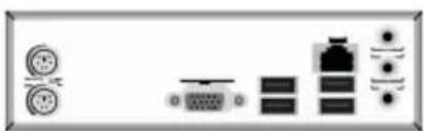
The motherboard is equipped with advanced full set of I/O ports in the rear panel, including PS/2 mouse and PS/2 keyboard connectors, one VGA port, one DVI port (or one HDMI port or none), one RJ45 LAN connector, four USB 2.0 ports, and audio jacks 6-ch for microphone, line-in and line-out.
In addition, this motherboard supports four SATA 3Gb/s connectors for expansion.

* When accommodating Intel 3^rd Generation CPU, the PCI Express 16X slot can run at Gen3 speed, which accelerates on 32GB/s rate that effectively delivers double of PCI Express Gen2 speed.
*2 The Intel 3^rd Generation CPU required.
Package Contents
Your motherboard package ships with the following items:
H61H2-MV Motherboard
□ User Manual
DVD
I/O Shield
☐ 2 SATA 3Gb/s Cables

The package contents above are for reference only, please take the actual package items as standard.
Specifications
| CPU | LGA1155 socket for 2^nd/3^rd Generation Intel® CoreTM Family/Pentium/Celeron ProcessorsNote: Please go to ECS website for the latest CPU support list. |
| Intel ® H61 ChipsetChipset | |
| Memory | Dual-channel DDR3 memory architecture2 x 240-pin DDR3 DIMM sockets support up to 16 GBSupports DDR3 1600 */1333/1066 MHz DDR3 SDRAMNote: * The Intel 3^rd Generation CPU required. |
| Expansion Slots | 1 x PCI Express x16 Gen3 slot1 x PCI Express x1 slot |
| Storage | Supported by Intel ® H61 Express Chipset- 4 x Serial ATA 3Gb/s devices |
| Audio | Realtek ALC662- 6 Channel High Definiton Audio Codec- Compliant with HD audio specification |
| LAN | Realtek 8111E Gigabit Lan- 10/100/1000 Fast Ethernet Controller-Wake-on-LAN and remote wake-up supportRealtek 8105- 10/100 LAN Controller-Wake-on-LAN and remote wake-up support |
| Rear Panel I/O | 1 x PS/2 keyboard and PS/2 mouse connectors1 x D-Sub port (VGA)1 x DVI port(or HDMI port or none)4 x USB 2.0 ports1 x RJ45 LAN connector1 x Audio port (1x Line in, 1x Line out, 1x Mic_in Rear) |
| Internal I/OConnectors & Headers | 1 x 24-pin ATX Power Supply connector1 x 4-pin 12V Power connector1 x 4-pin CPU_FAN connector1 x 3-pin SYS_FAN connector2 x USB 2.0 headers support additional four USB 2.0 ports4 x Serial SATA 3Gb/s connectors1 x COM header1 x Case open header1 x Front panel USB power select jumper1 x Rear USB/PS2 power select jumper1 x Front Panel audio header1 x Front Panel switch/LED header1 x Speaker header1 x ME_UNLOCK header1 x CLR_CMOS header |
| System BIOS | • AMI BIOS with 32Mb SPI Flash ROM- Supports Plug and Play, STR(S3)/STD(S4)- Supports Hardware Monitor- Supports ACPI & DMI- Supports Audio, LAN, can be disabled in BIOS- Supports UEFI BIOS- Supports Multi-language- Supports Dual/Triple-Monitor function- F7 hot key for boot up devices option- Supports AC'97/HD Audio auto detect (default)- Supports Pgup clear CMOS Hotkey (Has PS2 KB Model only) |
| AP Support | • Supports eBLU• Supports eDLU• Supports eSFWarning: Microsoft.NET Framework 3.5 is required. |
| Form Factor | • Micro-ATX Size, 195mm x 170mm |
Motherboard Components
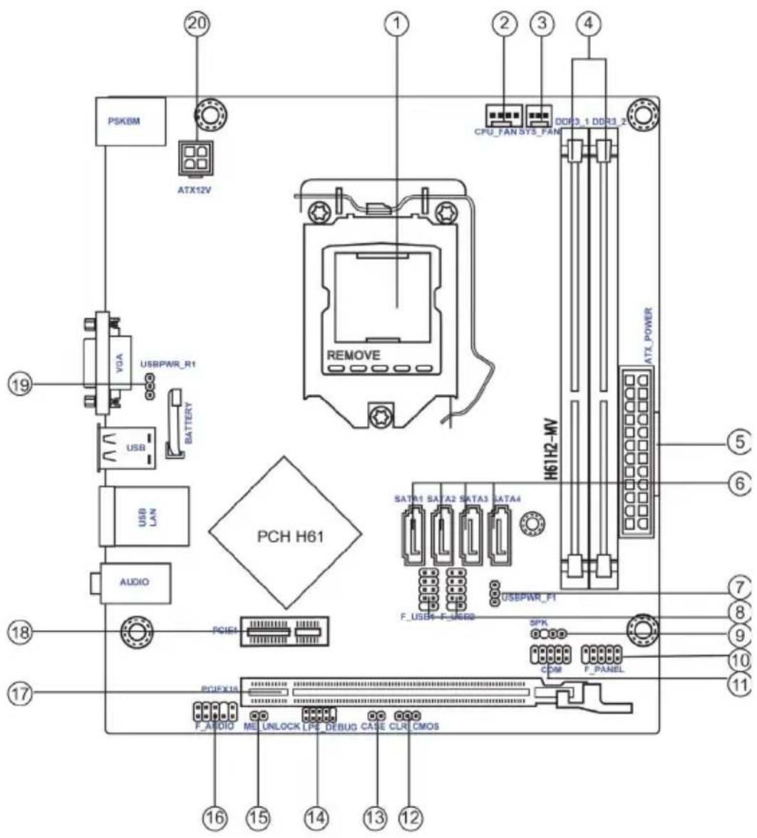
Table of Motherboard Components
| LABEL COMPONENTS | |
| 1. CPU Socket LGA11 | 55 socket |
| 2. CPU_FAN 4-pin CPU cooling fan connector | |
| 3. SYS_FAN 3-pin system cooling fan connector | |
| 4. DDR3_1~2 240-pin DDR3 Module slots | |
| 5. ATX_POWER Standard 24-pin ATX power connector | |
| 6. SATA1~4 Serial ATA 3.0 Gb/s connectors | |
| 7. USBPWR_F1 Front panel USB power select jumper | |
| 8. F_USB1~2 Front panel USB 2.0 header s | |
| 9. SPK Speaker header | |
| 10. F_PANEL Front panel switch/LED header | |
| 11. COM Onboard serial port header | |
| 12. CLR_CMOS Clear CMOS jumper | |
| 13. CASE CASE open header | |
| 14. LPC_DEBUG LPC debug header-for factory use only | |
| 15. ME_UNLOCK ME unlock header-for factory use only | |
| 16. F_AUDIO | Front panel audio header |
| 17. PCIEX16 | PCI Express slot for graphics interface |
| 18. PCIE1 | PCI Express x1 slot |
| 19. USBPWR_R1 | Rear USB/PS2 power select jumper |
| 20. ATX12V | 4-pin +12V power connector |
I/O Ports

- PS/2 Mouse(green)
Use the upper PS/2 port to connect a PS/2 mouse.
- PS/2 Keyboard(purple)
Use the lower PS/2 port to connect a PS/2 keyboard.
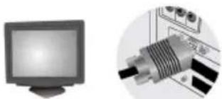
- VGA Port
Connect your monitor to the VGA port.
- USB 2.0 Ports
Use the USB 2.0 ports to connect USB 2.0 devices.
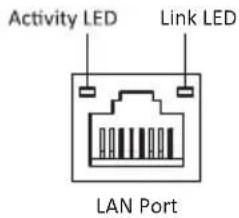
- LAN Port
Connect an RJ-45 jack to the LAN port to connect your computer to the Network.
| LAN LED Status | Description | |
| Activity LED | OFF No data | |
| Orange blinking | Active | |
| Link LED | OFF No link | |
| Green Link |
- Line-in(blue)
It can be connected to an external CD/DVD player, Tape player or other audio devices for audio input.
- Line-out(lime)
It is used to connect to speakers or headphones.
- Microphone(pink)
It is used to connect to a microphone.
About the Setup Utility
The computer uses the latest “American Megatrends Inc.” BIOS with support for Windows Plug and Play. The CMOS chip on the motherboard contains the ROM setup instructions for configuring the motherboard BIOS.
The BIOS (Basic Input and Output System) Setup Utility displays the system's configuration status and provides you with options to set system parameters. The parameters are stored in battery-backed-up CMOS RAM that saves this information when the power is turned off. When the system is turned back on, the system is configured with the values you stored in CMOS.
The BIOS Setup Utility enables you to configure:
- Hard drives, diskette drives and peripherals
• Video display type and display options - Password protection from unauthorized use
• Power Management features
The settings made in the Setup Utility affect how the computer performs. Before using the Setup Utility, ensure that you understand the Setup Utility options.
This chapter provides explanations for Setup Utility options.
The Standard Configuration
A standard configuration has already been set in the Setup Utility. However, we recommend that you read this chapter in case you need to make any changes in the future.
This Setup Utility should be used:
- when changing the system configuration
- when a configuration error is detected and you are prompted to make changes to the Setup Utility
- when trying to resolve IRQ conflicts
- when making changes to the Power Management configuration
- when changing the password or making other changes to the Security Setup
Entering the Setup Utility
When you power on the system, BIOS enters the Power-On Self Test (POST) routines. POST is a series of built-in diagnostics performed by the BIOS. After the POST routines are completed, the following message appears:
Press DEL to enter SETUP
Press the delete key to access BIOS Setup Utility.
| Main Advanced Chipset M.I.B III Boot Security Save & Exit | |
| BIOS InformationSystem Language [English]System Data [Fri 09/14/2012]System Time [00:00:31] | Choose the system default language. |
| → ← :Select Screen↑↓ :Select ItemEnter : Select+/- : Change Opt.F1:General HelpF2:Previous ValuesF3:Optimized DefaultsF4:Save & ExitESC:Exit | |
| Version 2.14.1219. Copyright (C) 2012, American Megatrends, Inc. | |
Resetting the Default CMOS Values
When powering on for the first time, the POST screen may show a "CMOS Settings Wrong" message. This standard message will appear following a clear CMOS data at factory by the manufacturer. You simply need to Load Default Settings to reset the default CMOS values.
Note: Changes to system hardware such as different CPU, memories, etc. may also trigger this message.

Using BIOS
When you start the Setup Utility, the main menu appears. The main menu of the Setup Utility displays a list of the options that are available. A highlight indicates which option is currently selected. Use the cursor arrow keys to move the highlight to other options. When an option is highlighted, execute the option by pressing
Some options lead to pop-up dialog boxes that prompt you to verify that you wish to execute that option. Other options lead to dialog boxes that prompt you for information.
Some options (marked with a triangle▶) lead to submenus that enable you to change the values for the option. Use the cursor arrow keys to scroll through the items in the submenu.
In this manual, default values are enclosed in parenthesis. Submenu items are denoted by a triangle▶.

The default BIOS setting for this motherboard apply for most conditions with optimum performance. We do not suggest users change the default values in the BIOS setup and take no responsibility to any damage caused by changing the BIOS settings.
BIOS Navigation Keys
The BIOS navigation keys are listed below:
| KEY FUNCTION | |
| ESC Exits the current menu | |
| ↑↓→← | Scrolls through the items on a menu |
| +/- | Change Opt. |
| Enter Select | |
| F1 General Help | |
| F2 Previous Value | |
| F3 Optimized Defaults | |
| F4 Save & Exit | |

For the purpose of better product maintenance, the manufacture reserves the right to change the BIOS items presented in this manual. The BIOS setup screens shown in this chapter are for reference only and may differ from the actual BIOS. Please visit the manufacture's website for updated manual.
Main Menu
When you enter the BIOS Setup program, the main menu appears, giving you an overview of the basic system information. Select an item and press
| Aptio Setup Utility - Copyright (C) 2012 American Megatrends, Inc. | |
| Main Advanced Chipset M.I.B III Boot Security Save & Exit | |
| BIOS InformationSystem Language [English]System Data [Fri 09/14/2012]System Time [00:00:31] | Choose the system default language. |
| → ← :Select Screen↑↓ :Select ItemEnter : Select+/- : Change Opt.F1:General HelpF2:Previous ValuesF3:Optimized DefaultsF4:Save & ExitESC:Exit | |
| Version 2.14.1219. Copyright (C) 2012, American Megatrends, Inc. | |
System Language (English)
This item is used to set system language.
Date & Time
The Date and Time items show the current date and time on the computer. If you are running a Windows OS, these items are automatically updated whenever you make changes to the Windows Date and Time Properties utility.
Advanced Menu
The Advanced menu items allow you to change the settings for the CPU and other system.
| Main Advanced Chipset M.I.B III Boot Security Save & Exit | |
| LAN ConfigurationPC Health StatusPower Management SetupACPI SettingsCPU ConfigurationSATA ConfigurationUSB ConfigurationSuper IO ConfigurationIntel (R) Smart Connect Technology | LAN Configuration Parameters |
| → ← :Select Screen↑↓ :Select ItemEnter : Select+/- : Change Opt.F1:General HelpF2:Previous ValuesF3:Optimized DefaultsF4:Save & ExitESC:Exit | |
| Version 2.14.1219. Copyright (C) 2012, American Megatrends, Inc. | |
▶ LAN Configuration
The item in the menu shows the LAN-related information that the BIOS automatically detects.
| Aptio Setup Utility - Copyright (C) 2012 American Megatrends, Inc. | |||||
| Main | Advanced | Chipset | M.I.B III | Boot | Security Save & Exit |
| LAN ConfigurationOnboard LAN Controller [Enabled] | Enabled/Disabled Onboard LAN 1 Controller | ||||
| → ← :Select Screen↑↓ :Select ItemEnter : Select+/- : Change Opt.F1:General HelpF2:Previous ValuesF3:Optimized DefaultsF4:Save & ExitESC:Exit | |||||
| Version 2.14.1219. Copyright (C) 2012, American Megatrends, Inc. | |||||
Onboard LAN Controller (Enabled)
Use this item to enable or disable the Onboard LAN.
Press
▶PC Health Status
On motherboards support hardware monitoring, this item lets you monitor the parameters for critical voltages, temperatures and fan speeds.
| Aptio Setup Utility - Copyright (C) 2012 American Megatrends, Inc. | ||||||
| Main | Advanced | Chipset | M.I.B III | Boot | Security | Save & Exit |
| PC Health Status | ||||||
| Smart Fan Function | ||||||
| CPU Fan Speed : 2824RPM | → ←:Select Screen↑↓:Select ItemEnter: Select+/-: Change Opt.F1:General HelpF2:Previous ValuesF3:Optimized DefaultsF4:Save & ExitESC:Exit | |||||
| CPU Voltage : | 1.056V | |||||
| DIMM Voltage : | 1.548V | |||||
| AXG Voltage : | 0.012V | |||||
| -- PECI Mode --Offset to TCC Activation Temp. : | -53 | |||||
| Version 2.14.1219. Copyright (C) 2012, American Megatrends, Inc. | ||||||
▶Smart Fan Function
Scroll to this item and press
| Aptio Setup Utility - Copyright (C) 2012 American Megatrends, Inc.Main Advanced Chipset M.I.B III Boot Security Save & Exit | |
| CPU Smart Fan Control [Enabled]Smart Fan Mode [Normal]Smart Fan start PWM value 180Smart Fan start PWM TEMP(-) 30Delta T 3Smart Fan Slope PWM value 10 PWM value/unitCPU Fan Full Speed Offset (-) 23 | |
| → ← :Select Screen↑↓ :Select ItemEnter : Select+/- : Change Opt.F1:General HelpF2:Previous ValuesF3:Optimized DefaultsF4:Save & ExitESC:Exit | |
| Version 2.14.1219. Copyright (C) 2012, American Megatrends, Inc. | |
CPU Smart Fan Control (Enabled)
This item allows you to enable/disable the control of the CPU fan speed by changing the fan voltage.
Smart Fan Mode (Normal)
This item allows you to select the fan mode (Normal, Quiet, Silent, or Manual) for a better operation environment. If you choose Normal mode, the fan speed will be auto adjusted depending on the CPU temperature. If you choose Quiet mode, the fan speed will be auto minimized for quiet environment. If you choose Silent mode, the fan speed will be auto restricted to make system more quietly. If you choose Manual mode, the fan speed will be adjust depending on users' parameters.
Smart Fan Start PWM value (180)
This item is used to set the start PWM value of the smart fan.
Smart Fan Start TEMP(-) (30)
This item is used to set the start temperature of the smart fan.
DeltaT (3)
This item specifies the range that controls CPU temperature and keeps it from going so high or so low when smart fan works.
SMART Fan Slope PWM value (10 PWM value/unite)
This item is used to set the Slope Select PWM of the smart fan.
CPU Fan Full Speed Offset(-) (23)
This item is used to set the CPU fan full speed offset value.
Press
System Component Characteristics
These items display the monitoring of the overall inboard hardware health events, such as CPU fan speed, CPU & DIMM voltage... etc.
- CPU Fan Speed
- CPU Voltage
- DIMM Voltage
- AXG Voltage
Press
▶Power Management Setup
This page sets up some parameters for system power management operation.
| Aptio Setup Utility - Copyright (C) 2012 American Megatrends, Inc. | ||||||
| Main | Advanced | Chipset | M.I.B III | Boot | Security | Save & Exit |
| Power Management SetupResume By RING Disabled]Resume By PME [Disabled]Resume By USB 1.x/2.0 (S3) [Disabled]Resume By PS2 KB (S3) [Disabled]Resume By PS2 MS (S3) [Disabled]EUP Function [Enabled]Power LED Type [Dual Color LED] | About Resume by Ring | |||||
| → ← :Select Screen↑↓ :Select ItemEnter : Select+/- : Change Opt.F1:General HelpF2:Previous ValuesF3:Optimized DefaultsF4:Save & ExitESC:Exit | ||||||
| Version 2.14.1219. Copyright (C) 2012, American Megatrends, Inc. | ||||||
Resume By RING (Disabled)
The system can be turned off with a software command. If you enable this item, the system can automatically resume if there is an incoming call on the Modem. You must use an ATX power supply in order to use this feature.
Resume By PME (Disabled)
The system can be turned off with a software command. If you enable this item, the system can automatically resume if there is an incoming call on the PCI Modem or PCI LAN card. You must use an ATX power supply in order to use this feature. Use this item to do wake-up action if inserting the PCI card.
Resume By USB 1.x/2.0(S3) (Disabled)
This item allows you to enable/disable the USB device wakeup function from S3 mode.
Resume By PS2 KB (S3) (Disabled)
This item enables or disables you to allow keyboard activity to awaken the system from power saving mode.
Resume By PS2 MS (S3) (Disabled)
This item enables or disables you to allow mouse activity to awaken the system from power saving mode.
EUP Function (Enabled)
This item allows user to enable or disable EUP function.
Power LED Type (Dual Color LED)
This item shows the type of the power LED.
Press
▶ACPI Setting
The item in the menu shows the highest ACPI sleep state when the system enters suspend.
| Aptio Setup Utility - Copyright (C) 2012 American Megatrends, Inc.Main Advanced Chipset M.I.B III Boot Security Save & Exit | |
| ACPI SettingsACPI Sleep State [S3 (Suspend to RAM)] | Select the highest ACPI sleep state the system will enter when the SUSPEND button is pressed. |
| → ←:Select Screen↑↓:Select ItemEnter : Select+/- : Change Opt.F1:General HelpF2:Previous ValuesF3:Optimized DefaultsF4:Save & ExitESC:Exit | |
| Version 2.14.1219. Copyright (C) 2012, American Megatrends, Inc. | |
ACPI Sleep State (S3(Suspend to RAM))
This item allows user to enter the ACPI S3 (Suspend toRAM) Sleep State (default).
Press
▶CPU Configuration
Scroll to this item and press
| Aptio Setup Utility - Copyright (C) 2012 American Megatrends, Inc. | |||||
| Main | Advanced | Chipset | M.I.B III | Boot | Security Save & Exit |
| CPU ConfigurationIntel(R) Core(TM) i5-3450K CPU @ 3.10GHz64-bit SupportedProcessor Speed 3100 MHzProcessor Stepping 306a8Microcode Revision 10Processor Cores 4Intel HT Technology Not SupportedIntel VT-x Technology SupportedActive Processor Cores [All]Limit CPUID Maximum [Disabled]Execute Disable Bit [Enabled]Intel Virtualization Technology [Enabled]CPU C3 Report [Disabled]CPU C6 Report [Enabled]Enhanced Halt (C1E) [Enabled] | Number of cores to enable in each processor package.→ ←:Select Screen↑↓:Select ItemEnter : Select+/- : Change Opt.F1:General HelpF2:Previous ValuesF3:Optimized DefaultsF4:Save & ExitESC:Exit | ||||
| Version 2.14.1219. Copyright (C) 2012, American Megatrends, Inc. | |||||
Intel(R) Core(TM) i5-3450K CPU @ 3.10GHz
This is display-only field and displays the information of the CPU installed in your computer.
64-bit (Supported)
This item shows the computer supports 64-bit.
Processor Speed (3100MHz)
This item shows the current processor speed.
Processor Stepping (306a8)
This item shows the processor stepping version.
Microcode Revision (10)
This item shows the Microcode version.
Processor Cores (4)
This item shows the core number of the processor.
Intel HT Technology (Not Supported)
This item shows that your computer supports Intel HT technology or not.
Intel VT-x Technology (Supported)
This item shows that your computer supports Intel VT-x technology or not.
Active Processor Cores (All)
Use this item to control the active processor cores.
Execute Disable Bit (Enabled)
This item allows the processor to classify areas in memory by where application code can execute and where it cannot. When a malicious worm attempts to insert code in the buffer, the processor disables code execution, preventing damage or worm propagation. Replacing older computers with Execute Disable Bit enabled systems can halt worm attacks, reducing the need for virus related repair.
Intel Virtualization Technology (Enabled)
When disabled, a VMM cannot utilize the additional hardware capabilities provided by Vandor Pool Technology.
CPU C3 Report (Disabled)
Use this item to enable or disable CPU C3(ACPI C2) report to OS.
CPU C6 Report (Enabled)
Use this item to enable or disable CPU C6(ACPI C3) report to OS.
Enhanced Halt (C1E) (Enabled)
Use this item to enable the CPU energy-saving function when the system is not running.
Press
▶SATA Configuration
Use this item to show the mode of serial SATA configuration options.
| Aptio Setup Utility - Copyright (C) 2012 American Megatrends, Inc. | |
| Main Advanced Chipset M.I.B III Boot Security Save & Exit | |
| SATA Configuration | Determines how SATA controller(s) operate. |
| SATA Mode [IDE Mode] | |
| SATA Port1 Not Present | |
| SATA Port2 Not Present | → ← :Select Screen↑↓ :Select ItemEnter : Select+/- : Change Opt.F1:General HelpF2:Previous ValuesF3:Optimized DefaultsF4:Save & ExitESC:Exit |
| SATA Port3 Not Present | |
| SATA Port4 Not Present | |
| Version 2.14.1219. Copyright (C) 2012, American Megatrends, Inc. | |
SATA Mode (IDE Mode)
Use this item to select SATA mode.
SATA Port 1\~4 (Not Present)
This motherboard supports four SATA channel and each channel allows one SATA device to be installed. Use these items to configure each device on the SATA channel.
Press
▶USB Configuration
Scroll to this item and press
| Aptio Setup Utility - Copyright (C) 2012 American Megatrends, Inc. | |
| Main Advanced Chipset M.I.B III Boot Security Save & Exit | |
| USB ConfigurationAll USB Devices [Enabled]Legacy USB Support [Enabled] | USB Support Parameters |
| → ← :Select Screen↑↓ :Select ItemEnter : Select+/- : Change Opt.F1:General HelpF2:Previous ValuesF3:Optimized DefaultsF4:Save & ExitESC:Exit | |
| Version 2.14.1219. Copyright (C) 2012, American Megatrends, Inc. | |
All USB Devices (Enabled)
Use this item to enable or disable all USB devices.
Legacy USB Support (Enabled)
Use this item to enable or disable support for legacy USB devices. Setting to Audio allows the system to detect the presence of the USB device at startup. If detected, the USB controller legacy mode is enabled. If no USB device is detected, the legacy USB support is disabled.
Press
▶ Super IO Configuration
Use this item to show the information of the Super IO Configuration.
| Aptio Setup Utility - Copyright (C) 2012 American Megatrends, Inc. | |
| Main Advanced Chipset M.I.B III Boot Security Save & Exit | |
| Super IO ConfigurationSuper IO Chip IT8758Serial Port 0Configuration | Set Parameters of Floppy Disk Controller (FDC) |
| → ← :Select Screen↑↓ :Select ItemEnter : Select+/- : Change Opt.F1:General HelpF2:Previous ValuesF3:Optimized DefaultsF4:Save & ExitESC:Exit | |
| Version 2.14.1219. Copyright (C) 2012, American Megatrends, Inc. | |
Super IO Chip (IT8758)
This item shows the information of the super IO chip.
▶ Serial Port 0 Configuration
Scroll to this item and press
| Aptio Setup Utility - Copyright (C) 2012 American Megatrends, Inc. | |||||
| Main | Advanced | Chipset | M.I.B III | Boot | Security Save & Exit |
| Serial Port 0 ConfigurationSerial Port [Enabled]Device Settings IO=3F8h; IRQ=4;Change Settings [Auto] | Enable or Disable Floppy Disk Controller→ ←:Select Screen↑↓ :Select ItemEnter : Select+/- : Change Opt.F1:General HelpF2:Previous ValuesF3:Optimized DefaultsF4:Save & ExitESC:Exit | ||||
| Version 2.14.1219. Copyright (C) 2012, American Megatrends, Inc. | |||||
Serial Port (Enabled)
This item allows you to enable or disable serial port.
Device Settings (IO=3F8h; IRQ=4)
This item shows the information of the device settings.
Change Settings (Auto)
Use this item to change device settings.
Press
▶Intel (R) Smart Connect Technology
Scroll to this item and press
| Aptio Setup Utility - Copyright (C) 2012 American Megatrends, Inc. | ||||||
| Main | Advanced | Chipset | M.I.B III | Boot | Security | Save & Exit |
| ISCT [Disabled] | Enable/Disable ISCTConfiguration | |||||
| → ← :Select Screen↑↓ :Select ItemEnter : Select+/- : Change Opt.F1:General HelpF2:Previous ValuesF3:Optimized DefaultsF4:Save & ExitESC:Exit | ||||||
| Version 2.14.1219. Copyright (C) 2012, American Megatrends, Inc. | ||||||
ISCT (Disabled)
Use this item to enable or disable ISCT Configuration.
Chipset Menu
The chipset menu items allow you to change the settings for the North chipset, South chipset and other system.
| Aptio Setup Utility - Copyright (C) 2012 American Megatrends, Inc. | |
| Main Advanced Chipset M.I.B III Boot Security Save & Exit | |
| System Agent ConfigurationPCH ConfigurationME Configuration | System Agent (SA) Parameters |
| → ← :Select Screen↑↓ :Select ItemEnter : Select+/- : Change Opt.F1:General HelpF2:Previous ValuesF3:Optimized DefaultsF4:Save & ExitESC:Exit | |
| Version 2.14.1219. Copyright (C) 2012, American Megatrends, Inc. | |
▶ System Agent Configuration
Scroll to this item and press
| Aptio Setup Utility - Copyright (C) 2012 American Megatrends, Inc.Main Advanced Chipset M.I.B III Boot Security Save & Exit | |
| System Agent ConfigurationIGD Memory [64M]DVMT Memory [256M]IGD Multi-Monitor [Disabled] | Select DVMT 5.0 Pre-Allocated (Fixed) Graphics Memory size used by the Internal Graphics Device. |
| → ← :Select Screen↑↓ :Select ItemEnter : Select+/- : Change Opt.F1:General HelpF2:Previous ValuesF3:Optimized DefaultsF4:Save & ExitESC:Exit | |
| Version 2.14.1219. Copyright (C) 2012, American Megatrends, Inc. | |
IGD Memory (64M)
This item shows the information of the IGD(Internal Graphics device) memory.
DVMT Memory (256M)
When set to Fixed Mode, the graphics driver will reserve a fixed position of the system memory as graphics memory, according to system and graphics requirements.
Press
Multi-Monitor technology
Multi-Monitor technology can help you to increase the area available for programs running on a single computer system through using multiple display devices.
It is not only to increase larger screen viewing but also to improving personal productivity.
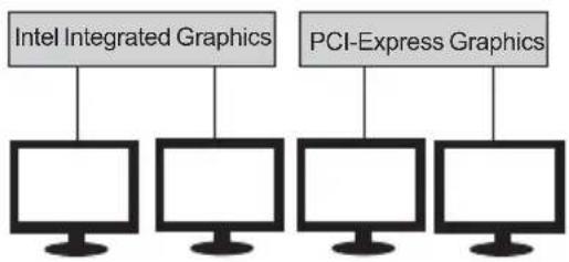
flowchart
graph TD
    A["Intel Integrated Graphics"] --> B["Computer"]
    C["PCI-Express Graphics"] --> D["Computer"]
    E["Computer"] --> F["Computer"]

Please note that Multi-Monitor technology supports up to four monitors: one or two Intel integrated Graphics and one or two PCI-Express graphics devices under Windows 7.
Step 1. Insert ECS drives DVD to run Auto setup or browse the DVD to install Intel chipset drivers, VGA and sound drivers.(If you want know the detail information, please refer to chapter 4.)

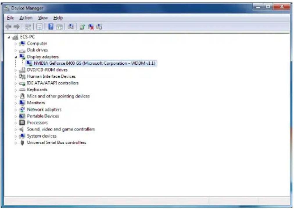
Step 2. Install all the drivers of PCI-Express graphic cards. Click the Browse CD item, then appears the following screen. Select the driver you want to install(e.g NVIDIA GeForce 8400 GS(Microsoft Corporation-WDDM v1.1)) and double click it.
Step 3. Enable IGD Multi-Monitor from BIOS. In the following BIOS screen, please set IGD Multi-Monitor to [Enabled].
| Aptio Setup Utility - Copyright (C) 2012 American Megatrends, Inc. | |
| Main Advanced Chipset M.I.B III Boot Security Save & Exit | |
| System Agent ConfigurationIGD Memory [64M]DVMT Memory [256M]IGD Multi-Monitor [Enabled] | Select DVMT 5.0 Pre-Allocated (Fixed) Graphics Memory size used by the Internal Graphics Device. |
| → ← :Select Screen↑↓ :Select ItemEnter : Select+/- : ValueF1:General HelpF2:Previous ValueF3:Optimized DefaultsF4:Save & ExitESC:Exit | |
| Version 2.14.1219. Copyright (C) 2012, American Megatrends, Inc. | |
Step 4. Change the appearance of your displays under Windows 7.
- Enter the Control Panel menu, select the Display in the All Control Panel Items and click the Screen Resolution, then appears the following screen.


- Select display devices, set the multiple displays option and to extend destop for display "Multi-Monitor technology".


▶ PCH Configuration
Scroll to this item and press
| Aptio Setup Utility - Copyright (C) 2012 American Megatrends, Inc. | |
| Main Advanced Chipset M.I.B III Boot Security Exit | |
| PCH ConfigurationRestore AC Power Loss [Power Off]Audio ConfigurationAzalia HD Audio [Enabled]Case Open Warning [Disabled]Chassis Opened [No] | Select AC power state when power is re-applied after a power failure.→ ← :Select Screen↑↓ :Select ItemEnter : Select+/- : Change Opt.F1:General HelpF2:Previous ValuesF3:Optimized DefaultsF4:Save & ExitESC:Exit |
| Version 2.14.1219. Copyright (C) 2012, American Megatrends, Inc. | |
Restore AC Power Loss (Power Off)
This item enables your computer to automatically restart or return to its operating status.
Audio Configuration
This item shows the information of the audio configuration.
Azalia HD Audio (Enabled)
This item enables or disables Azalia HD audio.
Case Open Warning (Disabled)
This item enables or disables the warning if the case is opened up, and the item below indicates the current status of the case.
Chassis Opened (No)
This item indicates whether the case has been opened.
Press
▶ ME Configuration
Scroll to this item and press
| Aptio Setup Utility - Copyright (C) 2012 American Megatrends, Inc.Main Advanced Chipset M.I.B III Boot Security Save & Exit | |
| Management Engine Technology ConfigurationME FW Version 8.1.0.1248 | |
| → ← :Select Screen↑↓ :Select ItemEnter : Select+/- : Change Opt.F1:General HelpF2:Previous ValuesF3:Optimized DefaultsF4:Save & ExitESC:Exit | |
| Version 2.14.1219. Copyright (C) 2012, American Megatrends, Inc. | |
ME FW Version (8.1.0.1248)
This item shows the ME version.
Press
M.I.B III (MB Intelligent BIOS III) Menu
This page enables you to set the clock speed and system bus for your system. The clock speed and system bus are determined by the kind of processor you have installed in your system.
| Aptio Setup Utility - Copyright (C) 2012 American Megatrends, Inc.Main Advanced Chipset M.I.B III Boot Security Save & Exit | |
| M.I.B III (MB Intelligent BIOS III)CPU OverClocking ConfigurationChipset OverClocking ConfigurationB.O.M.P Technology [Enabled]Auto Detect DIMM/PCI Clk [Enabled]Spread Spectrum [Enabled]Intel(R) Pentium (TM) i5-3450K CPU @ 3.10GHzProcessor Speed 3100 MHzMemory Frequency 1333 MHzTotal Memory 2048MB (DDR3 ) | CPU OverClocking Configuration→ ← :Select Screen↑↓ :Select ItemEnter : Select+/- : Change Opt.F1:General HelpF2:Previous ValuesF3:Optimized DefaultsF4:Save & ExitESC:Exit |
| Version 2.14.1219. Copyright (C) 2012, American Megatrends, Inc. | |
▶ CPU OverClocking Configuration
Scroll to this item to view the following screen:
| Aptio Setup Utility - Copyright (C) 2012 American Megatrends, Inc.Main Advanced Chipset M.I.B III Boot Security Save & Exit | |
| CPU OverClocking ConfigurationCPU Frequency 100CPU Ratio 31Enhanced Intel SpeedStep Technology [Enabled]Turbo Mode [Enabled]Internal PLL OverVoltage [Disabled]Runtime Turbo Enable [Disabled]Over Clocking Extra Vol.(1/256 V) 0IA Core Current MaximumiGFX Core Current MaximumLong Duration Power Limit Override MaximumLong Duration Power Maintained 10Short Duration Power Limit Override Maximum1 Core Ratio Limit 352 Core Ratio Limit 353 Core Ratio Limit 344 Core Ratio Limit 33Intel Graphics ConfigurationGraphics Core Ratio Limit 22Graphics Voltage(1/256) 0 | Enhanced Intel SpeedStep Technology→ ← :Select Screen↑↓ :Select ItemEnter : Select+/- : Change Opt.F1:General HelpF2:Previous ValuesF3:Optimized DefaultsF4:Save & ExitESC:Exit |
| Version 2.14.1219. Copyright (C) 2012, American Megatrends, Inc. | |
CPU Frequency (100)
This item shows the information of the CPU frequency.
CPU Ratio (31)
This item allows users to control non turbo CPU ratio.
Enhanced Intel SpeedStep Technology (Enabled)
This item allows users to enable or disable the EIST(Enhanced Intel SpeedStep Technology).
Turbo Mode (Enabled)
This item allows you to control the Intel Turbo Boost Technology.
Internal PLL OverVoltage (Disabled)
This item allows you to control the Internal PLL OverVoltage.
Runtime Turbo Enable (Disabled)
This item shows if CPU support runtime turbo or not.
Over Clocking Extra Vol.(1/256 V) (0)
Use this item to set over clocking extra voltage.
IA Core Current (Maximum)
Use this item to control CPU Current Limit.
iGFX Core Current (Maximum)
Use this item to control iGFX Core Current Limit.
Long Duration Power Limit Override (Maximum)
Intel(R) Turbo Boost Technology will use this power limit during the long duration power limit time window.
Long Duration Maintained (10)
Use this item to control the time window over PL1 value should be maintained. This is for Turbo mode.
Short Duration Power Limit Override (Maximum)
Intel(R) Turbo Boost Technology will use this power limit for a very short duration. After that, the long duration power limit will be honored.
1/2/3/4 Core Ratio Limit (35/35/34/33)
These items show the Core Ratio Limit value.
Graphics Core Ratio Limit (23)
This item allows you to control the internal GFX Turbo ratio.
Graphics Voltage(1/256) (0)
This item allows you to adjust the internal GFX voltage.
Press
▶ Chipset OverClocking Configuration
Scroll to this item to view the following screen:
| Aptio Setup Utility - Copyright (C) 2012 American Megatrends, Inc. | |
| Main Advanced Chipset M.I.B III Boot Security Save & Exit | |
| Memory Multiplier ConfigurationPerformance Memory Profiles [Automatic]XMP Profile 1 Not SupportedXMP Profile 2 Not Supported | The selection of Performance Memory Profiles which impacts memory sizing behavior. |
| Memory Timing ConfigurationCAS# Latency (tCL) 9RAS# to CAS# Delay (tRCD) 9Row Precharge Time (tRP) 9RAS# Active Time ( tRAS) 24Write Recovery Time (tWR) 10Row Refresh Cycle Time (tRFC) 74Active to Active Delay (tRRD) 4Write to Read Delay (tWTR) 5Read CAS# Precharge (tRTP) 5Four Active Window Delay (tFAW) 20 | → ← :Select Screen↑↓ :Select ItemEnter : Select+/- : Change Opt.F1:General HelpF2:Previous ValuesF3:Optimized DefaultsF4:Save & ExitESC:Exit |
| Version 2.14.1219. Copyright (C) 2012, American Megatrends, Inc. | |
Performance Memory Profiles (Automatic)
This item enables you to set the Performance Memory Profile.
XMP Profile 1/2 (Not Supported)
These items show the information of Performance Memory Profile.
CAS Latency (tCL) (9)
This item determines the operation of DDR SDRAM memory CAS (column address strobe). It is recommended that you leave this item at the default value. The 2T setting requires faster memory that specifically supports this mode.
RAS# to CAS# Delay (tRCD) (9)
This item specifies the RAS# to CAS# delay to Rd/Wr command to the same bank.
Row Precharge Time (tRP) (9)
This item specifies Row precharge to Active or Auto-Refresh of the same bank.
RAS# Active Time (tRAS) (24)
This item specifies the RAS# active time.
Write Recovery Time (tWR) (10)
This item specifies the write recovery time.
Row Refresh Cycle Time (tRFC) (74)
This item specifies the row refresh cycle time.
Active to Active Delay (tRRDmin) (4)
This item controls the ACTIVE bank x to ACTIVE bank y in memory clock cycles.
Write to Read Delay (twTR) (5)
This item specifies the write to read delay time.
Read CAS# Precharge (tRTP) (5)
This item controls the Read to PRECHARGE delay for memory devices, in memory clock cycles.
Four Active Window Delay (tFAW) (20)
This item controls the four bank activate time in memory clock cycles.
Press
B.O.M.P Technology (Enabled)
This item allows users to enable or disable B.O.M.P technology. This function can run safe setting to setup menu when system boot fail 3 times.
Auto Detect DIMM/PCI Clk (Enabled)
When this item is enabled, BIOS will disable the clock signal of free DIMM/PCI slots.
Spread Spectrum (Enabled)
If you enable spread spectrum, it can significantly reduce the EMI (Electro-Magnetic Interference) generated by the system.
Intel(R) Core (TM) i5-3450K CPU @ 3.10GHz
This is display-only field and displays the information of the CPU installed in your computer.
Processor Speed (3100 MHz)
This item shows the CPU speed.
Memory Frequency (1333MHz)
This item shows the momery frequency.
Total Memory (2048MB(DDR3))
This item shows the total momery of DDR3.
Boot Menu
This page enables you to set the boot device priority.

| Aptio Setup Utility - Copyright (C) 2012 American Megatrends, Inc.Main Advanced Chipset M.I.B III Boot Security Save & Exit | |
| Boot ConfigurationOperation System Select [Windows 7 or other OS]Launch PXE OpROM [Disabled]Launch Storage OpROM [Enabled]Bootup NumLock State [On]Quiet Boot [Enabled]Boot mode select [LEGACY] | Windows 7 or other OS: Boot policy for Legacy OSWindows 8: Boot Policy for UEFI OS without Compatibility Support Module (CSM)Manual: User customized CSM parameters & boot policy |
| Set Boot PriorityBoot Option #1 [Hard Disk]Boot Option #2 [CD/DVD]Boot Option #3 [USB/Floppy]Boot Option #4 [USB CD/DVD]Boot Option #5 [USB Hard Disk]Boot Option #6 [USB Flash]Boot Option #7 [Network] | → ← :Select Screen↑↓ :Select ItemEnter : Select+/- : Change Opt.F1:General HelpF2:Previous ValuesF3:Optimized DefaultsF4:Save & ExitESC:Exit |
| Version 2.14.1219. Copyright (C) 2012, American Megatrends, Inc. | |
Boot Configuration
This item shows the information of the boot configuration.
Operation System Select (Windows7 or other OS)
This item is used to select the operation system.
Launch PXE OpROM (Disabled)
Use this item to enable or disable the PXE OpROM.
Launch Storage OpROM (Enabled)
Use this item to enable or disable the Storage OpROM.
Bootup NumLock State (On)
This item determines if the NumLock key is active or inactive at system start-up time.
Quiet Boot (Enabled)
This item determines if the NumLock key is active or inactive at system start-up time.
Boot mode select (LEGACY)
Use this item to select boot mode.
Boot Option #1/#2/#3/#4/#5/#6/#7/ (Hard Disk / CD/DVD / USB/Floppy / USB CD/DVD / USB HardDisk / USB Flash / Network)
These items show the boot priorities.
Security Menu
This page enables you to set setup administrator and password.
| Aptio Setup Utility - Copyright (C) 2012 American Megatrends, Inc. | ||||||
| Main | Advanced | Chipset | M.I.B III | Boot | Security | Save & Exit |
| Administrator Password Status Not InstallUser Password Status Not Install | Set Setup Administrator Password | |||||
| Administrator PasswordSystem Mode state SetupSecure Boot state DisabledSecure Boot [Disabled] | → ← :Select Screen↑↓ :Select ItemEnter : Select+/- : Change Opt.F1:General HelpF2:Previous ValuesF3:Optimized DefaultsF4:Save & ExitESC:Exit | |||||
| Version 2.14.1219. Copyright (C) 2012, American Megatrends, Inc. | ||||||
Administrator Password
This item allows you to set up the administrator password.
User Password Status
This item shows the status of the user password.
System Mode state (Setup)
This item shows system mode setup or not.
Secure Boot state (Disabled)
This item allows you to enable or disable the secure boot state.
Secure Boot (Enabled)
This item is used to control the secure boot flow, it is possible only if system runs in User Mode.
Save & Exit Menu
This page enables you to exit system setup after saving or without saving the changes.
| Aptio Setup Utility - Copyright (C) 2012 American Megatrends, Inc.Main Advanced Chipset M.I.B III Boot Security Save & Exit | |
| Save Changes and ResetDiscard Changes and ExitDiscard Changes and Reset | Exit system setup after saving the changes. |
| Save OptionsSave ChangesDiscard ChangesRestore DefaultsSave as User DefaultsRestore User DefaultsBoot Override | → ← :Select Screen↑↓ :Select ItemEnter : Select+/- : Change Opt.F1:General HelpF2:Previous ValuesF3:Optimized DefaultsF4:Save & ExitESC:Exit |
| Version 2.14.1219. Copyright (C) 2012, American Megatrends, Inc. | |
Save Changes and Reset
This item enables you to save the changes that you have made and reset.
Discard Changes and Exit
This item enables you to discard any changes that you have made and exit.
Discard Changes and Reset
This item enables you to discard any changes that you have made and reset.
Save Options
This item enables you to save the options that you have made.
Save Changes
This item enables you to save the changes that you have made.
Discard Changes
This item enables you to discard any changes that you have made.
Restore Defaults
This item enables you to restore the system defaults.
Save as User Defaults
This item enables you to save the changes that you have made as user defaults.
This item enables you to restore user defaults.
Boot Override
Use this item to select the boot device.
Updating the BIOS
You can download and install updated BIOS for this motherboard from the manufacturer's Web site. New BIOS provides support for new peripherals, improvements in performance, or fixes for known bugs. Install new BIOS as follows:
1 If your motherboard has a BIOS protection jumper, change the setting to allow BIOS flashing.
2 If your motherboard has an item called Firmware Write Protect in Advanced BIOS features, disable it. (Firmware Write Protect prevents BIOS from being overwritten.)
3 Prepare a bootable device or create a bootable system disk. (Refer to Windows online help for information on creating a bootable system disk.)
4 Download the Flash Utility and new BIOS file from the manufacturer's Web site. Copy these files to the bootable device.
5 Turn off your computer and insert the bootable device in your computer. (You might need to run the Setup Utility and change the boot priority items on the Advanced BIOS Features Setup page, to force your computer to boot from the bootable device first.)
6 At the C:\ or A:\ prompt, type the Flash Utility program name and the file name of the new BIOS and then press
7 When the installation is complete, remove the bootable device from the computer and restart your computer. If your motherboard has a Flash BIOS jumper, reset the jumper to protect the newly installed BIOS from being overwritten. The computer will restart automatically.
This concludes Chapter 3. Refer to the next chapter for information on the software supplied with the motherboard.
Memo
Chapter 2
Chapter 3
Using the Motherboard Software
Auto-installing under Windows XP/7/8
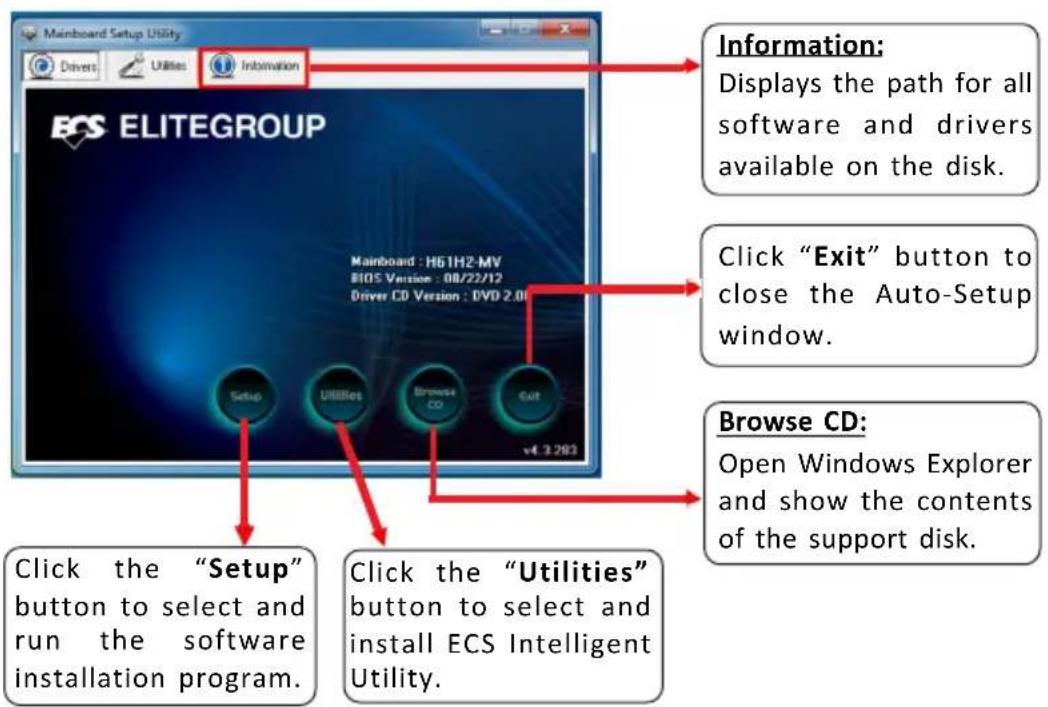
The auto-install DVD-ROM makes it easy for you to install the drivers and software. The support software DVD-ROM disc loads automatically under Windows XP/7/8. When you insert the DVD-ROM disc in the DVD-ROM drive, the auto-run feature will automatically bring up the installation screen. The screen has four buttons on it: Setup, Utilities, Browse CD and Exit.
Running Setup
Follow these instructions to install device drivers and software for the motherboard:
- Click Setup. The installation program begins:


The following screens are examples only. The screens and driver lists will be different according to the motherboard you are installing.
The motherboard identification is located in the upper left-hand corner.
- Click Next. The following screen appears:

- Check the box next to the items you want to install. The default options are recommended.
- Click Next to run the Installation Wizard. An item installation screen appears:
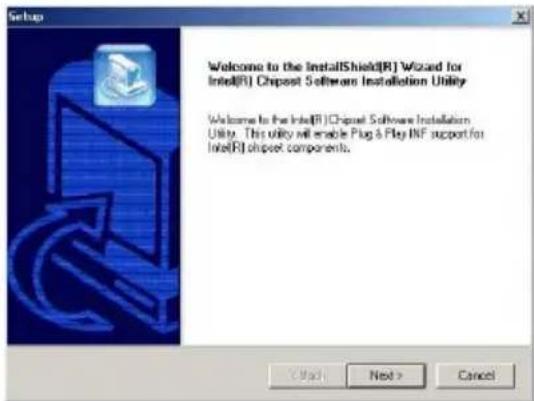
- Follow the instructions on the screen to install the items.

Drivers and software are automatically installed in sequence. Follow the onscreen instructions, confirm commands and allow the computer to re-start a few times to complete the installation.
Windows 8 will show the following screen after system restart, you must select "Desktop" in the bottom left to install the next driver.

Windows 7/8 will appear below UAC (User Account Control) message after the system restart. You must select "Yes" to install the next driver. Continue this process to complete the drivers installation.

Manual Installation
If the auto-install DVD-ROM does not work on your system, you can still install drivers through the file manager for your OS (for example, Windows Explorer). Look for the chipset and motherboard model, and then browse to the directory and path to begin installing the drivers. Most drivers have a setup program (SETUP.EXE) that automatically detects your operating system before installation. Other drivers have the setup program located in the operating system subfolder.
If the driver you want to install does not have a setup program, browse to the operating system subfolder and locate the readme text file (README.TXT or README.DOC) for information on installing the driver or software for your operating system.
ECS Utility Software (Intelligent EZ Utility)
ECS Intelligent EZ Utility provides friendly interfaces under Windows O.S, which makes your computing more easily and conveniently.

These software(s) are subject to change at anytime without prior notice. Please refer to the support disk for available software.
eSF
eSF(Smart Fan) utility provides easy and safe way to adjust fan speed in accordance with your PC's system loading and temperature.
It has five modes to adjust fan speed in a safe range without entering the BIOS to optimize your system cooling environment.

eDLU
ECS eDLU utility makes updating drivers fast and easy. eDLU saves time and hassle by listing all the latest drivers online. Just select the one you prefer and start to download and install the drivers.

eBLU
ECS eBLU utility makes BIOS update faster and easier. eBLU will list the latest BIOS with a default check-mark. Click"install" button to install.

H61H2-MV USER MANUAL
Chapter 4
Trouble Shooting
Start up problems during assembly
After assembling the PC for the first time you may experience some start up problems. Before calling for technical support or returning for warranty, this chapter may help to address some of the common questions using some basic troubleshooting tips. You may also log onto our ECS website for more information: http://www.ecs.com.tw/ECSWebSite/Support/Support_FAQ.aspx?MenuID=49&childid=M_49&LanID=0
a) System does not power up and the fans are not running.
- Disassemble the PC to remove the VGA adaptor card, DDR memory, LAN, USB and other peripherals including keyboard and mouse. Leave only the motherboard, CPU with CPU cooler and power supply connected. Make sure the power cord is plugged into the wall socket & the switch on the Power Supply Unit (PSU) is turned "on" as well. Turn on again to see if the CPU and power supply fans are running.
- Make sure to remove any unused screws or other metal objects such as screwdrivers from the inside PC case. This is to prevent damage from short circuit.
- Check the CPU FAN connector is connected to the motherboard.
- For Intel platforms check the pins on the CPU socket for damage or bent. A bent pin may cause failure to boot and sometimes permanent damage from short circuit.
- Check the 12V power connector is connected to the motherboard.
- Check that the 12V power & ATX connectors are fully inserted into the motherboard connectors. Make sure the latches of the cable and connector are locked into place.
b) Power is on, fans are running but there is no display
- Make sure the monitor is turned on and the monitor cable is properly connected to the PC.
- Check the VGA adapter card (if applicable) is inserted properly.
- Listen for beep sounds. If you are using internal PC speaker make sure it is connected.
a. continuous 3 short beeps: memory not detected
b. 1 long beep and 8 short beeps: VGA not detected
c) The PC suddenly shuts down while booting up.
-
The CPU may experience overheating so it will shutdown to protect itself. Apply the thermal grease onto the CPU heatsink & ensure the CPU fan is well-connected with the CPU heatsink. Check if the CPU fan is working properly while the system is running.
-
From the BIOS setting, try to disable the Smartfan function to let the fan run at default speed. Doing a Load Optimised Default will also disable the Smartfan.
Start up problems after prolong use
After a prolong period of use your PC may experience start up problems again. This may be caused by breakdown of devices connected to the motherboard such as HDD, CPU fan, etc. The following tips may help to revive the PC or identify the cause of failure.
- Clear the CMOS values using the CLR_CMOS jumper. Refer to CLR_CMOS jumper in Chapter 2 for Checking Jumper Settings in this user manual. When completed, follow up with a Load Optimised Default in the BIOS setup.
- Check the CPU cooler fan for dust. Long term accumulation of dust will reduce its effectiveness to cool the processor. Clean the cooler or replace a new one if necessary.
- Check that the 12V power & ATX connectors are fully inserted into the motherboard connectors. Make sure the latches of the cable and connector are locked into place.
- Remove the hard drive, optical drive or DDR memory to determine which of these components may be at fault.
- Check whether there is any bulked up electrolytic capacitor or abnormal component.
Please logo onto our ECS website: http://www.ecs.com.tw/ECSWebSite/Support/Technical Support List.aspx?MenuID=50&LanID=0 for more information.
Maintenance and care tips
Your computer, like any electrical appliance, requires proper care and maintenance. Here are some basic PC care tips to help prolong the life of the motherboard and keep it running as best as it can.
- Keep your computer in a well ventilated area. Leave some space between the PC and the wall for sufficient airflow.
- Keep your computer in a cool dry place. Avoid dusty areas, direct sunlight and areas of high moisture content.
- Routinely clean the CPU cooler fan to remove dust and hair.
- In places of hot and humid weather you should turn on your computer once every other week to circulate the air and prevent damage from humidity.
- Add more memory to your computer if possible. This not only speeds up the system but also reduces the loading of your hard drive to prolong its life span.
- If possible, ensure the power cord has an earth ground pin directly from the wall outlet. This will reduce voltage fluctuation that may damage sensitive devices.
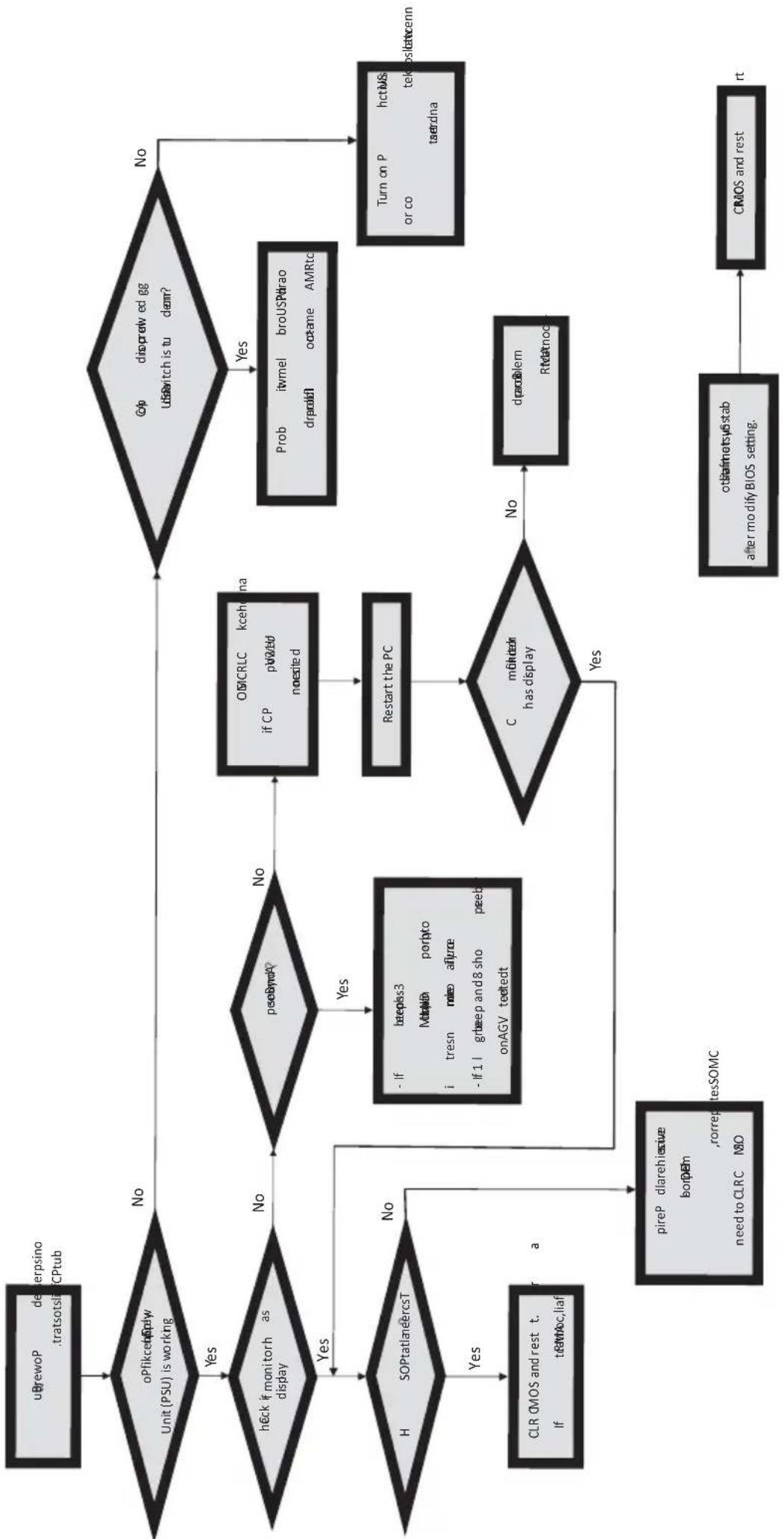
Basic Troubleshooting Flowchart
flowchart
graph TD
    A["uBrewoP deverpsino .tratsotslrc CPtub"] --> B{oPfikcebify Unit (PSU) is working}
    B -->|Yes| C{heck if monitorh as display}
    B -->|No| D{peobnd?}
    C -->|Yes| E{H SOPtatlanercsT}
    C -->|No| F["Yes"]
    E -->|Yes| G["CLR CMOS and rest t. If texAoc,liaf a"]
    E -->|No| H["pireP dlarehisive borPem ,rorrepitesSOMC need to CLRC MO"]
    D -->|No| I["OMCRLC kcehanna if CP pW2bd noesited"]
    I --> J["Restart the PC"]
    J --> K{C moktor has display}
    K -->|Yes| L["Other netsis tab after modify BIOS setting."]
    K -->|No| M["dran blem Rmtnocn"]
    M --> N["Turn on P hctUS or co tekoslatcenn taerdna"]
    D -->|No| O{Cp discrewed gg UsSwitch is tu dem?}
    O -->|Yes| P["Prob itvmel broUSPhrao drpaoln octame AMRto"]
    O -->|No| Q["CMOS and rest start"]
Memo
Chapter 4
Hardware Installation Guide
Installation Steps
Step1. Installation of the CPU and CPU Cooler:
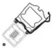
1-1. Pull up the lever away from the socket.
1-3. Rotate and press down the fastener of CPU fan to the motherboard through holes to install CPU fan into place.
1-2. Align the CPU cut edge with the indented edge of the CPU socket. Gently place the CPU into correct position. Apply an even layer of thermal grease on the surface of CPU.

natural_image
Two technical diagrams showing mechanical components with no visible text or symbols1-4. Connect the CPU cooler power connector to the CPU_FAN connector.


Step2. Installation of Memory Modules:
2-1. Unfasten the latches on each side of the DIMM slots.

natural_image
3D diagram of a mechanical component with a yellow curved arrow indicating motion or force (no text or symbols)2-2. Firmly press the DIMM down until it seats correctly. Make sure the slot latches are levered upwards and latch on the edge of the DIMM.

Step3. Installation of Motherboard:
3-1. Replace the back I/O plate of the case with the I/O shield provided in motherboard's package.
3-2. Place the motherboard within the case by positioning it into the I/O plate. Secure the motherboard to the case with screws.
natural_image
Pure electrical circuit lines without any symbols
natural_image
Interior view of a computer tower case showing internal components like CPU socket and drive bays (no visible text or labels)Step4. Installation of storage devices:
4-1. Please remove the front cover and 5.25" plate from the case.
4-2. Place the storage devices (IDE/SATA/FDD) in its position within the case and secure the device with screws.

natural_image
Close-up of a computer printer's front panel and side cover (no visible text or labels)
natural_image
Close-up of a computer tower case with ventilation slots and drive bays (no visible text or labels)Step5. Case Preparation and Installation of Power Supply:
Remove both sides and the lid of the case, and then install the power supply with screws.

It is recommended to use a power supply delivering more than 300W of power. Insufficient power supply may cause unstable boot-up.

natural_image
Close-up of a computer drive casing with visible fan and cooling element (no text or symbols)Step6. Installation of an Expansion card:
Remove the metal located on the slot and then insert the expansion card into the slot. Press the card firmly to make sure it is fully inserted into its slot. And then return the screw back to its position.

natural_image
3D rendered mechanical component with mounting holes and a central fan (no visible text or symbols)Step7. Connecting Cables and Power Connectors:
a. Connect the SATA hard drive to its SATA cable
b. Connect SATA power connector to the SATA device

natural_image
Close-up of a metallic staircase with multiple metal frames (no visible text or symbols)
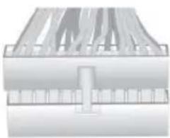
c. Connect 24-pin power cable
Please note that when installing 24-pin power cable, the latches of power cable and the ATX connector match perfectly.
d. Connect 4-pin power cable
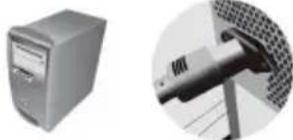
The ATX_12V 4-Pin power connector is used to provide power to the CPU. When installing 4-pin power cable, the latch of power cable matches the ATX_12V connector perfectly.
natural_image
3D rendering of a mechanical component with internal channels and mounting holes (no text or symbols)
Step 8: Connecting ports on the case:
Once the steps above have been completed, please connect the peripherals such as the keyboard, mouse, monitor, etc. Then, connect the power and turn on the system. Please install all the required software.

Please install all peripheral devices.
8-1. Keyboard connection

natural_image
Close-up of a keyboard and a connector (no visible text or symbols)8-2. Printer connection

natural_image
Two grayscale images: one showing a printer outline and the other showing a pen inserted into a device (no text or symbols visible)8-3. Monitor connection 8-4. Speaker connection
natural_image
Illustration of a vintage computer monitor and a close-up of a cable connector (no text or symbols visible)
natural_image
Two views of a speaker setup: one with two speakers and the other showing a control panel (no text or symbols visible)8-5. Power connection 8-6. Mouse connection

natural_image
Two technical illustrations: a desktop tower and a close-up of a mechanical component (no visible text or symbols)
natural_image
Two grayscale images: one showing a computer mouse with a cable, the other showing a close-up of a device (no text or symbols visible)
To prevent component damage, do not power up the system until the installation is complete.
Using BIOS
The BIOS (Basic Input and Output System) Setup Utility displays the system's configuration status and provides you options to set system parameters. When you power on the system, BIOS enters the Power-On Self Test (POST) routines, please press or F2 to enter setup. When powering on for the first time, the POST screen may show a "CMOS Settings Wrong" message. Please enter BIOS and choose "Load Default Settings" to reset the default CMOS values. (Changes to system hardware such as different CPU, memories, etc. may also trigger this message.)
BIOS Navigation Keys
| KEY | FUNCTION |
| ESC | Exits the current menu |
| ↑↓→← | Scrolls through the items on a menu |
| +/- | Modifies the selected field's values |
| Enter Select | |
| F1 | General Help |
| F2 | Previous Value |
| F3 | Optimized Defaults |
| F4 | Save & Exit |

The sequence of installation may differ depending on the type of case and devices used.
natural_image
Two technical line drawings of a mechanical component, possibly a housing or enclosure, with no visible text or symbols.natural_image
3D rendering of a mechanical component with grooves and a highlighted green arc (no text or symbols)natural_image
Pure electrical circuit lines without any symbols
natural_image
Interior view of a computer tower case showing CPU socket, drive bays, and monitor (no visible text or labels)natural_image
Close-up of a printer's front panel showing paper feed and paper tray (no text or symbols visible)
natural_image
Close-up of a computer tower case with visible internal components (no text or symbols)natural_image
Close-up of a computer tower case with visible fan and ventilation slots (no text or symbols)
natural_image
3D rendering of a mechanical component with no visible text or symbolsnatural_image
Close-up of a mechanical component with multiple curved slots (no visible text or symbols)
natural_image
Cross-sectional view of a mechanical component with internal channels and a central slot (no text or symbols visible)
Por favor, instale todos os dispositivos periféricos.
8-1. Conexão de teclado
natural_image
Close-up of a keyboard and a close-up of a mechanical component (no visible text or symbols)
natural_image
Two grayscale images: one showing a printer with a screen, the other showing a close-up of a printer's internal structure (no text or symbols visible)natural_image
Illustration of a vintage computer monitor and a mechanical component (no text or symbols visible)
natural_image
Two views of a speaker setup: one with two speakers and the other showing a control panel (no visible text or symbols)natural_image
Two grayscale images: one of a desktop computer tower and another showing a mechanical component (no visible text or symbols)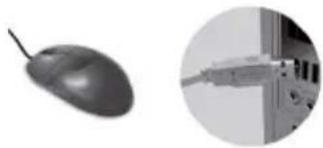
natural_image
Computer mouse and a close-up of a device (no visible text or symbols)
natural_image
Two technical diagrams showing mechanical components with no visible text or symbols
natural_image
3D diagram of a mechanical component with internal grooves and a highlighted yellow curved section (no text or symbols)natural_image
Pure electrical circuit lines without any symbols
natural_image
Interior view of a computer tower case showing internal components and ventilation duct (no visible text or labels)natural_image
Exterior view of a gray computer printer with ventilation slots and drive bays (no text or symbols visible)
natural_image
Close-up of a computer tower case with visible internal components (no text or symbols)natural_image
Close-up of a computer tower case with visible ventilation slots and fan (no text or symbols)natural_image
3D rendered mechanical component with circular features and mounting holes (no visible text or symbols)natural_image
Close-up of a mechanical component with multiple grooves or slots (no visible text or symbols)
natural_image
3D rendering of a mechanical component with internal channels and mounting holes (no text or symbols)
natural_image
Close-up of a keyboard and a close-up of a computer mouse (no visible text or symbols)natural_image
Illustration of a CRT monitor and a cable connector (no text or symbols visible)8-5. परवाँ कनेक्शन
natural_image
Two grayscale images: one of a desktop computer tower and another showing a mechanical component (no visible text or symbols)8-2. पूरिटर कनेक्शन

natural_image
Two grayscale images showing a printer and its close-up view of the same device (no text or symbols visible)8-4. सपीकर कने क्शन
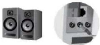
natural_image
Two electronic speakers with speaker stands and a close-up of the front panel showing a control interface (no text or symbols visible)8-6. माउस कनेक्शन

natural_image
Computer mouse and a close-up of a device (no visible text or symbols)
natural_image
Two technical diagrams showing mechanical components with no visible text or symbolsnatural_image
Pure mechanical component diagram without any text, numbers, or symbolsnatural_image
Pure electrical circuit lines without any symbols
natural_image
Interior view of a computer case showing internal components and ventilation slots (no visible text or labels)natural_image
Close-up of a computer tower with ventilation slots and drive bays (no visible text or labels)
natural_image
Close-up of a computer tower case showing internal components and ventilation slots (no text or symbols visible)natural_image
Close-up of a computer drive casing with visible fan blades and ventilation slots (no text or symbols)
natural_image
3D rendered mechanical component with no visible text or symbolsnatural_image
Close-up of a mechanical component with multiple cylindrical parts arranged diagonally (no visible text or symbols)
natural_image
3D diagram of a mechanical component with internal channels and mounting holes (no text or symbols)
natural_image
Close-up of a keyboard and a close-up of a device with a pen inserted (no visible text or symbols)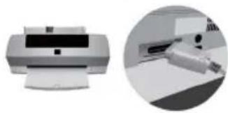
natural_image
Two grayscale images: one showing a printer with a screen, the other showing a close-up of a printer's handle (no visible text or symbols)natural_image
Illustration of a vintage CRT monitor and a cable connector (no text or symbols)
natural_image
Illustration of two audio/video speakers with speaker stands and a close-up of the speaker's control panel (no text or symbols visible)natural_image
Two grayscale images: a desktop tower and a close-up of a mechanical component (no visible text or symbols)natural_image
Computer mouse and a close-up of a device (no visible text or symbols)
natural_image
Two identical mechanical component diagrams with no visible text, numbers, or symbolsnatural_image
3D rendering of a mechanical component with a yellow highlighted section (no text or symbols visible)natural_image
Pure electrical circuit lines without any symbols
natural_image
Interior view of a computer tower case showing internal components like CPU socket and drive bays (no visible text or labels)natural_image
Close-up of a gray electronic device with ventilation slots and a handle (no visible text or symbols)
natural_image
Close-up of a computer tower with ventilation slots and a lid (no visible text or symbols)natural_image
Close-up of a computer case with a fan and ventilation grille (no visible text or symbols)
natural_image
3D rendering of a mechanical or electronic component with no visible text or symbolsnatural_image
Close-up of a mechanical component with multiple cylindrical parts (no visible text or symbols)
natural_image
3D rendered mechanical component with internal channels and a central shaft (no text or symbols visible)
natural_image
Close-up of a keyboard and a close-up of a device with a cable (no visible text or symbols)natural_image
Two grayscale images showing a printer and a close-up of its mechanical component (no visible text or symbols)natural_image
Illustration of a vintage computer monitor and a cable connector (no text or symbols)
natural_image
Two views of a speaker setup: one with two speakers and the other showing a close-up of a device (no text or symbols visible)natural_image
Two grayscale images: one of a desktop computer tower and another close-up of a mechanical component (no visible text or symbols)8-6. Maus-Anschluss
natural_image
Two grayscale images: one showing a computer mouse with a cable, the other showing a close-up of a mechanical component (no text or symbols visible)
natural_image
3D diagram of a mechanical component with a yellow curved arrow indicating rotation or movement (no text or symbols)
natural_image
Pure electrical circuit lines without any symbols
natural_image
Interior view of a computer case with visible CPU socket and drive bays (no text or symbols)natural_image
Close-up of a computer printer with ventilation slots and paper feed (no visible text or labels)
natural_image
Close-up of a computer tower case showing front panel and drive slots (no visible text or labels)natural_image
Close-up of a mechanical device with visible internal components and a label 'TEM OCHI' (no other text or symbols)natural_image
3D mechanical component with mounting holes and a central circular feature (no visible text or symbols)natural_image
Close-up of a mechanical component with multiple curved slots (no visible text or symbols)
natural_image
Cross-sectional view of a mechanical component or housing (no visible text or symbols)

natural_image
Two technical diagrams showing mechanical components with no visible text or symbolsnatural_image
Pure mechanical component diagram without any text, numbers, or symbolsnatural_image
Pure electrical circuit lines without any symbolsnatural_image
Interior view of a computer tower case showing internal components and wiring (no visible text or labels)natural_image
Close-up of a gray computer printer with ventilation slots and paper feed (no visible text or labels)
natural_image
Close-up of a computer tower case with visible internal components (no text or symbols)natural_image
Close-up of a computer drive casing with visible fan blades (no text or symbols)natural_image
3D mechanical assembly diagram showing internal components and mounting holes (no text or labels)natural_image
Close-up of a mechanical component with multiple curved slots and a central handle (no visible text or symbols)
natural_image
3D rendering of a mechanical component with internal channels and mounting holes (no text or symbols)
natural_image
Close-up of a keyboard and a close-up of a door handle (no text or symbols visible)natural_image
Illustration of a vintage CRT monitor and a mechanical component (no text or symbols visible)natural_image
Two grayscale images: one of a desktop computer tower and another showing a mechanical component (no visible text or symbols)natural_image
Two grayscale images: one showing a printer outline and the other showing a printer with paper (no text or symbols visible)natural_image
Two views of a speaker setup: one with two speakers and another with a control panel (no visible text or symbols)natural_image
Computer mouse and a close-up of a device with ports (no visible text or symbols)
natural_image
Two technical diagrams showing mechanical components with no visible text or symbolsnatural_image
3D diagram of a mechanical component with internal grooves and a highlighted curved section (no text or symbols)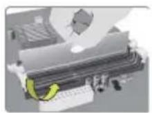
Langkah 3. Pemasangan Motherboard:
natural_image
Pure electrical circuit lines without any symbols
natural_image
Interior view of a computer case with visible drive bays and internal components (no text or labels)natural_image
Close-up of a white electronic device with ventilation slots and a paper feed (no visible text or symbols)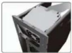
natural_image
Close-up of a mechanical device with a lid and mounting holes (no visible text or symbols)natural_image
Close-up of a computer case with visible internal components and ventilation slots (no text or symbols)
natural_image
3D mechanical component with mounting holes and a central circular feature (no visible text or symbols)natural_image
Industrial machinery with conveyor belts and conveyor systems (no visible text or symbols)
c. Sambungkan kabel daya 24 pin
natural_image
Cross-sectional view of a mechanical component with internal channels and a central mounting bracket (no text or symbols visible)
natural_image
Close-up of a keyboard and a close-up of a mechanical component (no visible text or symbols)
natural_image
Two grayscale images: one showing a printer outline and the other showing a printer with a close-up view (no text or symbols visible)8-3. Sambungan monitor 8-4. Sambungan speaker

natural_image
Illustration of a CRT monitor and a cable connector (no text or symbols)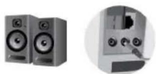
natural_image
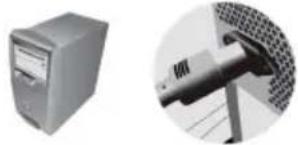
Two views of a speaker setup: one with two speakers and another with a control panel (no visible text or symbols)8-5. Sambungan daya
natural_image
Two grayscale images: one of a desktop computer tower and another showing a mechanical component (no visible text or symbols)8-6. Sambungan mouse
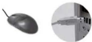
natural_image
Computer mouse and a close-up of a cable inserted into a device (no visible text or symbols)
natural_image
Two technical diagrams showing mechanical components with no visible text or symbolsnatural_image
Pure mechanical component diagram without any text, numbers, or symbolsnatural_image
Interior view of a computer tower case showing internal components and ventilation duct (no visible text or labels)
natural_image
Pure electrical circuit lines without any symbolsnatural_image
Close-up of a computer monitor case with visible internal components (no text or symbols)
natural_image
Close-up of a printer's front panel showing paper feed and paper tray (no text or symbols visible)
natural_image
Close-up of a computer case with visible internal components and ventilation slots (no text or symbols)natural_image
3D mechanical component with visible slots and mounting holes (no text or symbols)natural_image
Close-up of a mechanical component with no visible text or symbolsnatural_image
Pure mechanical component diagram without any text, numbers, or symbols

2-8 توصيل الطابعة
natural_image
Two grayscale images: one showing a printer with a screen, the other showing a printer with a paper (no visible text or symbols)4-8 نوصيل السماعة

natural_image
Close-up of a keyboard and a close-up of a device with a cable (no visible text or symbols)natural_image
Two electronic speakers with speaker stands and a close-up of the front panel showing ports and buttons (no visible text or symbols)8-6 توصيل الفارة

natural_image
Illustration of a vintage computer monitor and a close-up of a mechanical connector (no text or symbols)natural_image
Computer mouse and a close-up of a USB cable inserted into a device (no visible text or symbols)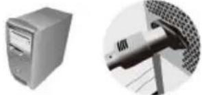
natural_image
Two grayscale images: one of a desktop computer tower and another showing a mechanical component inserted into a grid-patterned structure (no text or symbols visible)natural_image
Two technical diagrams showing mechanical components with no visible text or symbolsnatural_image
3D rendering of a mechanical component with a yellow curved arrow indicating motion or force (no text or symbols visible)natural_image
Pure electrical circuit lines without any symbols
natural_image
Interior view of a computer tower case showing internal components like CPU socket and drive bays (no visible text or labels)4. 安装储存装置:
natural_image
Close-up of a gray printer with ventilation slots and paper feed (no visible text or symbols)
natural_image
Close-up of a computer tower case showing internal components and ventilation slots (no text or symbols visible)5. 安装电源装置:
natural_image
Close-up of a mechanical device with a cylindrical component and a metallic housing (no visible text or symbols)6. 安装扩充卡:
natural_image
3D mechanical component with mounting holes and a central fan (no visible text or symbols)7. 连接电源线与电源接头:
a. 将SATA电缆连接至SATA硬盘
b. 将SATA电源接头连接至SATA设备

natural_image
Close-up of a mechanical component with multiple grooves and bolts (no visible text or symbols)
natural_image
3D rendering of a mechanical component with internal channels and mounting holes (no text or symbols)
8. 连接机箱端口:
安装所有外围设备:
8-1. 连接键盘

natural_image
Close-up of a keyboard and a close-up of a device with a cable (no visible text or symbols)8-3. 连接显示器

natural_image
Illustration of a computer monitor and a close-up of a cable connector (no text or symbols visible)8-5. 连接电源

natural_image
Two grayscale images: a desktop tower and a close-up of a mechanical component (no visible text or symbols)8-2. 连接打印机
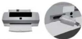
natural_image
Two grayscale images: one showing a printer outline and another showing a printer with a paper clip (no visible text or symbols)8-4. 连接喇叭

natural_image
Two views of a speaker setup: one with two speakers and another with a control panel (no visible text or symbols)8-6. 连接鼠标

natural_image
Computer mouse and a close-up of a cable connector (no visible text or symbols)
安装所有外围设备:
8-1. 连接键盘
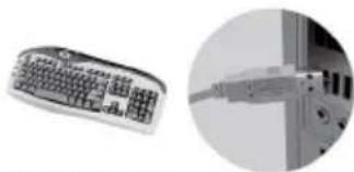
natural_image
Close-up of a keyboard and a close-up of a device with a cable (no visible text or symbols)8-3. 连接显示器

8-5. 连接电源
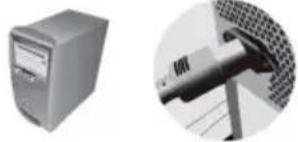
natural_image
Two grayscale images: one of a desktop computer tower and another showing a mechanical component (no visible text or symbols)8-2. 连接打印机
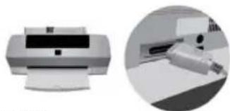
natural_image
Two grayscale images: one showing a printer outline and another showing a printer with a paper clip (no visible text or symbols)8-4. 连接喇叭

natural_image
Two views of a speaker setup: one with two speakers and another with a control panel (no visible text or symbols)8-6. 连接鼠标

natural_image
Computer mouse and a close-up of a cable connector (no visible text or symbols)
natural_image
Close-up of a computer tower case with ventilation slots and ventilation duct (no visible text or labels)
natural_image
Close-up of a computer tower case showing front panel and internal components (no text or symbols visible)natural_image
Close-up of a computer tower case with visible ventilation slots and a cable inserted (no text or symbols)6단계.확장 카드 설치하기:
natural_image
3D mechanical component with mounting holes and a central circular feature (no visible text or symbols)natural_image
Close-up of a mechanical component with multiple cylindrical parts (no visible text or symbols)
natural_image
Pure mechanical component diagram without any text, numbers, or symbols
8단계.케이스의 포트 연결하기:
모든 주변 기기를 설치합니다.
8-1.키보드연결
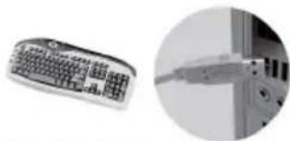
natural_image
Close-up of a keyboard and a close-up of a computer monitor (no visible text or symbols)8-3.모니터 연결
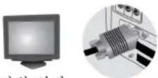
natural_image
Illustration of a computer monitor and a close-up of a cable connector (no text or symbols visible)8-5. 전원 연결

natural_image
Two grayscale images: a desktop computer tower and a mechanical component with mesh texture (no visible text or symbols)8-2.프린터 연결
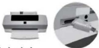
natural_image
Two grayscale images showing a printer and a close-up of its mechanical component (no visible text or symbols)8-4.스피커 연결

natural_image
Two views of a speaker setup: one with two speakers and another with a control panel (no visible text or symbols)8-6.마우스 연결

natural_image
Two grayscale images: one showing a computer mouse with a cable, the other showing a close-up of a device (no visible text or symbols)
- CASE

- ME_UNLOCK
UNLOCK

LOCK
- CLR_CMOS Jumper

CLR CMOS
1-2: NORMAL
2-3: CLEAR CMOS
Before clearing the CMOS, make sure to turn off the system.
- USBPWR_R1(Rear USB PS/2 Power Select Jumper)

VCC
(Default)

1
2
3
5VSB
- USBPWR_F1(Front Panel USB Power Select Jumper)

VCC
(Default)

3
2
1
5VSB

- Disclaimer
- Trademark Recognition
- Federal Communications Commission (FCC)
- Declaration of Conformity
- Canadian Department of Communications
- Preface i
- Chapter 1 1
- Introducing the Motherboard 1
- Chapter 27
- Using BIOS 7
- Chapter 3 37
- Using the Motherboard Software 57
- Chapter 4 41
- Trouble Shooting 41
- Multi-language Quick Installation Guide 45
- Appendix 79
- Header Pin Definition and Jumper Setting 79
- Introduction
- Package Contents
- Motherboard Components
- I/O Ports
- About the Setup Utility
- The Standard Configuration
- Entering the Setup Utility
- Resetting the Default CMOS Values
- Using BIOS
- BIOS Navigation Keys
- Main Menu
- System Language (English)
- Date & Time
- Advanced Menu
- ▶ LAN Configuration
- Onboard LAN Controller (Enabled)
- ▶PC Health Status
- ▶Smart Fan Function
- CPU Smart Fan Control (Enabled)
- Smart Fan Mode (Normal)
- Smart Fan Start PWM value (180)
- Smart Fan Start TEMP(-) (30)
- DeltaT (3)
- SMART Fan Slope PWM value (10 PWM value/unite)
- CPU Fan Full Speed Offset(-) (23)
- System Component Characteristics
- ▶Power Management Setup
- Resume By RING (Disabled)
- Resume By PME (Disabled)
- Resume By USB 1.x/2.0(S3) (Disabled)
- Resume By PS2 KB (S3) (Disabled)
- Resume By PS2 MS (S3) (Disabled)
- EUP Function (Enabled)
- Power LED Type (Dual Color LED)
- ▶ACPI Setting
- ACPI Sleep State (S3(Suspend to RAM))
- ▶CPU Configuration
- ▶SATA Configuration
- SATA Mode (IDE Mode)
- SATA Port 1\~4 (Not Present)
- ▶USB Configuration
- All USB Devices (Enabled)
- Legacy USB Support (Enabled)
- ▶ Super IO Configuration
- Super IO Chip (IT8758)
- ▶ Serial Port 0 Configuration
- Serial Port (Enabled)
- Device Settings (IO=3F8h; IRQ=4)
- Change Settings (Auto)
- ▶Intel (R) Smart Connect Technology
- ISCT (Disabled)
- Chipset Menu
- ▶ System Agent Configuration
- IGD Memory (64M)
- DVMT Memory (256M)
- Multi-Monitor technology
- ▶ PCH Configuration
- Restore AC Power Loss (Power Off)
- Audio Configuration
- Azalia HD Audio (Enabled)
- Case Open Warning (Disabled)
- Chassis Opened (No)
- ▶ ME Configuration
- ME FW Version (8.1.0.1248)
- M.I.B III (MB Intelligent BIOS III) Menu
- ▶ CPU OverClocking Configuration
- CPU Frequency (100)
- CPU Ratio (31)
- Enhanced Intel SpeedStep Technology (Enabled)
- Turbo Mode (Enabled)
- Internal PLL OverVoltage (Disabled)
- Runtime Turbo Enable (Disabled)
- Over Clocking Extra Vol.(1/256 V) (0)
- IA Core Current (Maximum)
- iGFX Core Current (Maximum)
- Long Duration Power Limit Override (Maximum)
- Long Duration Maintained (10)
- Short Duration Power Limit Override (Maximum)
- 1/2/3/4 Core Ratio Limit (35/35/34/33)
- Graphics Core Ratio Limit (23)
- Graphics Voltage(1/256) (0)
- ▶ Chipset OverClocking Configuration
- Performance Memory Profiles (Automatic)
- XMP Profile 1/2 (Not Supported)
- CAS Latency (tCL) (9)
- RAS# to CAS# Delay (tRCD) (9)
- Row Precharge Time (tRP) (9)
- RAS# Active Time (tRAS) (24)
- Write Recovery Time (tWR) (10)
- Row Refresh Cycle Time (tRFC) (74)
- Active to Active Delay (tRRDmin) (4)
- Write to Read Delay (twTR) (5)
- Read CAS# Precharge (tRTP) (5)
- Four Active Window Delay (tFAW) (20)
- B.O.M.P Technology (Enabled)
- Auto Detect DIMM/PCI Clk (Enabled)
- Spread Spectrum (Enabled)
- Intel(R) Core (TM) i5-3450K CPU @ 3.10GHz
- Processor Speed (3100 MHz)
- Memory Frequency (1333MHz)
- Total Memory (2048MB(DDR3))
- Boot Menu
- Boot Configuration
- Operation System Select (Windows7 or other OS)
- Launch PXE OpROM (Disabled)
- Launch Storage OpROM (Enabled)
- Bootup NumLock State (On)
- Quiet Boot (Enabled)
- Boot mode select (LEGACY)
- Security Menu
- Administrator Password
- User Password Status
- System Mode state (Setup)
- Secure Boot state (Disabled)
- Secure Boot (Enabled)
- Save & Exit Menu
- Save Changes and Reset
- Discard Changes and Exit
- Discard Changes and Reset
- Save Options
- Save Changes
- Discard Changes
- Restore Defaults
- Save as User Defaults
- Boot Override
- Updating the BIOS
- Chapter 3
- Using the Motherboard Software
- Auto-installing under Windows XP/7/8
- Running Setup
- Manual Installation
- ECS Utility Software (Intelligent EZ Utility)
- eSF
- eDLU
- eBLU
- H61H2-MV USER MANUAL
- Chapter 4
- Trouble Shooting
- Start up problems during assembly
- a) System does not power up and the fans are not running.
- b) Power is on, fans are running but there is no display
- c) The PC suddenly shuts down while booting up.
- Start up problems after prolong use
- Maintenance and care tips
- Hardware Installation Guide
- Installation Steps
- Step1. Installation of the CPU and CPU Cooler:
- Step2. Installation of Memory Modules:
- Step3. Installation of Motherboard:
- Step4. Installation of storage devices:
- Step5. Case Preparation and Installation of Power Supply:
- Step6. Installation of an Expansion card:
- Step7. Connecting Cables and Power Connectors:
- Step 8: Connecting ports on the case:
- Langkah 3. Pemasangan Motherboard:
- 安装储存装置:
- 安装电源装置:
- 安装扩充卡:
- 连接电源线与电源接头:
- 连接机箱端口:
Brand : ECS
Model : H61H2-MV-DVI
Category : Motherboard