JBR550 - Radio JENSEN - Free user manual and instructions
Find the device manual for free JBR550 JENSEN in PDF.

| Product Type | Tabletop Radio |
| Brand | Jensen |
| Model | JBR550 |
| Dimensions (W x H x D) | 10.5 x 6.3 x 4.7 inches (approx.) |
| Weight | 1.5 lbs (approx.) |
| Power Supply | AC 120V 60Hz or DC 9V (6 x AA batteries, not included) |
| Tuning Range | AM 530-1710 kHz, FM 88-108 MHz |
| Main Functions | AM/FM radio, telescopic antenna, volume control, tuning knob, built-in speaker, headphone jack, LED power indicator |
| Care and Cleaning | Wipe with a soft dry cloth; do not use liquid cleaners or abrasives; keep away from moisture and heat |
| Safety | Do not expose to rain or moisture; unplug during lightning storms; use only supplied power adapter; avoid object insertion into vents |
| Spare Parts and Reparability | Contact Jensen customer service for authorized replacement parts. Device is not user-serviceable except battery replacement. |
| General Information | Designed for home or office use. Compact and portable. May also feature an auxiliary input (3.5mm) for external devices. |
Frequently Asked Questions - JBR550 JENSEN
User questions about JBR550 JENSEN
0 question about this device. Answer the ones you know or ask your own.
Ask a new question about this device
Download the instructions for your Radio in PDF format for free! Find your manual JBR550 - JENSEN and take your electronic device back in hand. On this page are published all the documents necessary for the use of your device. JBR550 by JENSEN.
USER MANUAL JBR550 JENSEN
AM/FM/CD AUDIO SYSTEM with PA
Installation and Operation Manual
text_image
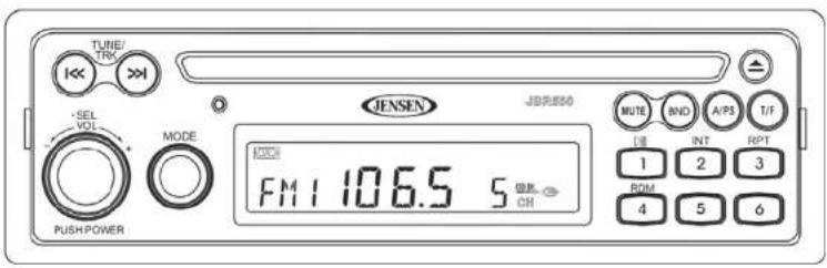
TUNE/ TRK JENSEN JBRUSO MUTE BND A/P3 T/F SEL VOL MODE 1000 FM 1 106.5 S PUSH POWER RPT 1 2 3 ROM 4 5 6JENSEN
JBR550
CONTENTS
System Features.... 1
Safety Information 2
Installation.... 3
Basic Operation 6
Tuner Operation....8
CD Player Operation....9
Care and Maintenance.... 10
Troubleshooting.... 10
Specifications 11
SYSTEM FEATURES
Features of the Jensen JBR550 mobile audio system include:
• AM/FM Tuner with 30 Presets (12 AM, 18 FM)
• Single In-Dash CD Player
- Public Announcement (PA) Feature with Optional Microphone (sold separately)
• M u t e
• Electronic Bass, Treble, Balance and Fader Controls
• C I o c k
Content List
• Jensen Main Chassis
- Hardware Kit
• Wiring Harnesses (4-pin and 9-pin)
- Installation Manual
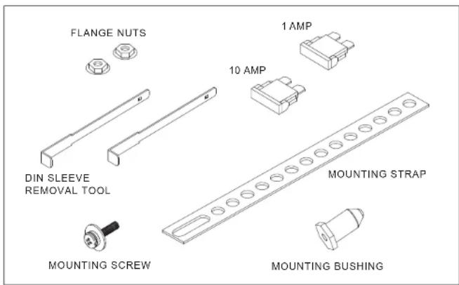
Hardware Kit
text_image
FLANGE NUTS 1 AMP 10 AMP DIN SLEEVE REMOVAL TOOL MOUNTING STRAP MOUNTING SCREW MOUNTING BUSHINGJENSEN
JBR550
SAFETY INFORMATION
When Driving
Keep the volume level low enough to be aware of the road and traffic conditions.
When Washing your Vehicle
Do not expose the product to water or excessive moisture. Moisture can cause electrical shorts, fire or other damage.
When Parked
Parking in direct sunlight can produce very high temperatures inside your vehicle. Give the interior a chance to cool down before starting playback.
Use the Proper Power Supply
This product is designed to operate with a 12 volt DC negative ground battery system.
Protect the Disc Mechanism
Avoid inserting any foreign objects into the disc slot. Misuse may cause malfunction or permanent damage due to the precise mechanism of this unit.
CAUTION:
THIS MOBILE CD PLAYER IS A CLASS I LASER PRODUCT. THIS UNIT USES A VISIBLE/ INVISIBLE LASER BEAM WHICH COULD CAUSE HAZARDOUS RADIATION IF EXPOSED DIRECTLY. BE SURE TO OPERATE THE MOBILE CD PLAYER AS INSTRUCTED. USE OF CONTROLS OR ADJUSTMENTS, OR PERFORMANCE OR PROCEDURES OTHER THAN THOSE SPECIFIED HEREIN MAY RESULT IN HAZARDOUS RADIATION EXPOSURE.
DO NOT OPEN COVERS AND DO NOT REPAIR BY YOURSELF. PLEASE REFER SERVICING TO A QUALIFIED TECHNICIAN.
WARNING:
• TO REDUCE THE RISK OF FIRE OR ELECTRIC SHOCK, DO NOT EXPOSE THIS EQUIPMENT TO RAIN OR MOISTURE.
• TO REDUCE THE RISK OF FIRE OR ELECTRIC SHOCK AND ANNOYING INTERFERENCE, USE ONLY THE RECOMMENDED ACCESSORIES.
DISC NOTES
Depending on the recording status, conditions of the disc, and the equipment used for recording, some CD-Rs/CD-RWs may not play on this unit. For more reliable playback, please adhere to the following recommendations:
- Use CD-RWs with speed 1x to 4x and write with speed 1x to 2x.
- Use CD-Rs with speed 1x to 8x and write with speed 1x to 2x.
- Do not play a CD-RW which has been written more than 5 times.
NOTE: CD-R and CD-RW discs will not play unless the recording session is closed and the CD is finalized.
Disc Maintenance
- A dirty or defective disc may cause sound dropouts while playing. Before playing, wipe the disc using a clean cloth, working from the center hole towards the outside edge. Never use benzene, thinners, cleaning fluids, anti-static liquids or any other solvent.

Insert label side up.

Do not bend.

Never touch the under side of the disc.
Wipe clean from the center to the edge.
- Be sure to use only round CDs for this unit and do not use any special shape CDs. Use of special shape CDs may cause the unit to malfunction.
- Do not stick paper or tape on the disc. Do not use CDs with labels or stickers attached or that have sticky residue from removed stickers.
- Do not expose discs to direct sunlight or heat sources.
NOTE: A disc may become scratched (although not enough to make it unusable) depending on how you handle it and other conditions in the usage environment. These scratches are not an indication of a problem with the player.
INSTALLATION
Before You Begin
- Disconnect Battery
Before you begin, always disconnect the battery negative terminal. - Remove Transport Screws
Important Notes
• Before final installation, test the wiring connections to make sure the unit is connected properly and the system works.
- Use only the parts included with the unit to ensure proper installation. The use of unauthorized parts can cause malfunctions.
- Consult with your nearest dealer if installation requires the drilling of holes or other modifications to your vehicle.
• Install the unit where it does not interfere with driving and cannot injure passengers if there is a sudden or emergency stop.
- If the installation angle exceeds 30^ from horizontal, the unit may not give optimum performance.
- Avoid installing the unit where it will be subject to high temperatures from direct sunlight, hot air, or from a heater, or where it would be subject to excessive dust, dirt or vibration.
DIN Radio Installation
This unit is designed for installation in vehicle cabs with an existing 1-DIN radio opening. In many cases, a special installation kit will be required to mount the radio to the dashboard. These kits are available at electronics supply stores and car stereo specialty shops. Always check the kit application before purchasing to make sure the kit works with your vehicle.
Universal Installation (Using Mounting Sleeve)
- Slide the mounting sleeve off of the chassis. If it is locked into position, use the removal keys (supplied) to disengage it.
- Check the dashboard opening size by sliding the mounting sleeve into it. If the opening is not large enough, carefully cut or file as necessary until the sleeve slides easily into the opening. Do not force the sleeve into the opening or cause it to bend or bow. Check that there will be sufficient space behind the dashboard for the radio chassis. Connect wires prior to actually installing the sleeve. Pigtail wiring should take place after hole size is confirmed. Mount sleeve after wiring.
- Follow the wiring diagram carefully and make certain all connections of the wiring harness are properly secured and insulated to insure proper operation of this unit. After completing the wiring connections, turn the unit on to confirm operation (ignition switch must be "on"). If unit does not operate, recheck all wiring until the problem is corrected. Once proper operation is achieved, turn off ignition switch and proceed with final mounting of the chassis.
- Locate the series of bend tabs along the top, bottom, and sides of the mounting sleeve. With the sleeve fully inserted into the dash opening, bend tabs outward so that the sleeve is firmly secured to the dashboard.
- Carefully slide the radio into the mounting sleeve making sure it is right side up until it is fully seated and the spring clips lock it into place.
- Attach one end of the perforated mounting strap (supplied) to the screw stud on the rear of the chassis using the flange nut provided. Fasten the other end of the perforated strap
to a secure part of the dashboard, either above or below the radio using the screw and flange nut provided. Bend the strap to position it as necessary.
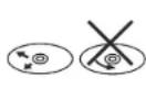
CAUTION: The rear of the radio must be supported with either the perforated strap or the rubber mounting bushing to prevent damage to the dashboard from the weight of the radio or improper operation due to vibration.
text_image
PERFORATED SUPPORT STRAP SECURE THIS END TO REAR OF RADIO DIN MOUNTING SLEEVE LOCKING TABS REAR SUPPORT SCREW SECURE THIS END TO SUB-DASH STRUCTURE MOUNTING SURFACE OPENING NOTE: IF OPENING DOES NOT EXIST, USE MOUNTING SLEEVE AS A TEMPLATE AND CUT OPENING. FILE EDGES TO FIT IF NECESSARY. DO NOT OVER FILE. REMOVAL KEYSKit Installation
- If your radio requires the use of an installation kit to mount this radio, follow the instructions included in the kit to attach the radio to the mounting plate supplied with the kit.
- Wire and test the radio as described.
- Install the radio/mounting plate assembly to the sub-dash according to the instructions of the installation kit.
- Attach the support strap to the radio and dashboard as described above.
- Replace the dashboard trim panel.
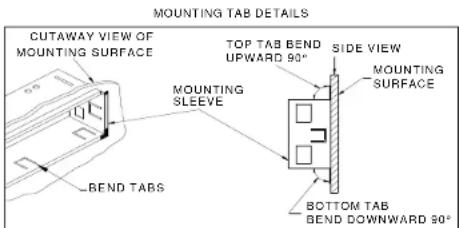
text_image
MOUNTING TAB DETAILS CUTAWAY VIEW OF MOUNTING SURFACE TOP TAB BEND UPWARD 90° SIDE VIEW MOUNTING SURFACE MOUNTING SLEEVE BOTTOM TAB BEND DOWNWARD 90° BEND TABSWiring Diagram
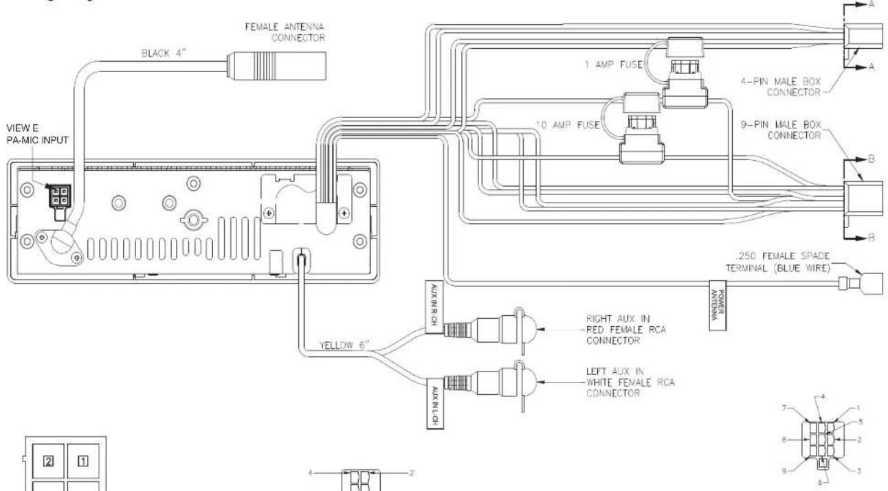
text_image
FEMALE ANTENNA CONNECTOR BLACK 4" VIEW E PA-MIC INPUT 1 AMP FUSE 10 AMP FUSE 4-PIN MALE BOX CONNECTOR 9-PIN MALE BOX CONNECTOR .250 FEMALE SPADE TERMINAL (BLUE WIRE) POWER ANTENA AUX IN-RCH YELLOW 6" AUX IN-LCH RIGHT AUX IN RED FEMALE RCA CONNECTOR LEFT AUX IN WHITE FEMALE RCA CONNECTOR 7 4 1 5 2 9 3 4 2 2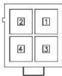
VIEW E PA_MIC INPUT
| PIN NO. | 4PIN SOCKET |
| 1 | MIC(+) |
| 2 | MIC(-) |
| 3 | MIC SWITCH(+) |
| 4 | MIC SWITCH(-) |
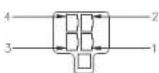
VIEW A-A WIRE INSERTION VIEW
| PIN NO. | WIRE COLOR | GAUGE | DESCRIPTION |
| 1 | GREEN | 20 | LEFT REAR SPEAKER (+) |
| 2 | VIOLET | 20 | RIGHT REAR SPEAKER (+) |
| 3 | GREEN/BLACK | 20 | LEFT REAR SPEAKER (-) |
| 4 | VIOLET/BLACK | 20 | RIGHT REAR SPEAKER (-) |
VIEW B-B INSERTION VIEW
| PIN NO. | WIRE COLOR | GAUGE | DESCRIPTION |
| 1 | EMPTY | - | NO CONNECTION |
| 2 | WHITE/BLACK | 20 | LEFT FRONT SPEAKER (-) |
| 3 | EMPTY | - | NO CONNECTION |
| 4 | WHITE | 20 | LEFT FRONT SPEAKER (+) |
| 5 | GRAY/BLACK | 20 | RIGHT FRONT SPEAKER (-) |
| 6 | GRAY | 20 | RIGHT FRONT SPEAKER (+) |
| 7 | RED | 20 | +12V SWITCHED (WITH/1A FUSE) |
| 8 | YELLOW | 18 | +12V BATTERY (WITH/10A FUSE) |
| 9 | BLACK | 18 | GROUND |
Reconnecting the Battery
When wiring is complete, reconnect the battery negative terminal.
Removing the Unit
To remove the radio after installation, insert the removal keys straight back until they click, and then pull the radio out. If removal keys are inserted at an angle, they will not lock properly to release the unit.
BASIC OPERATION
text_image
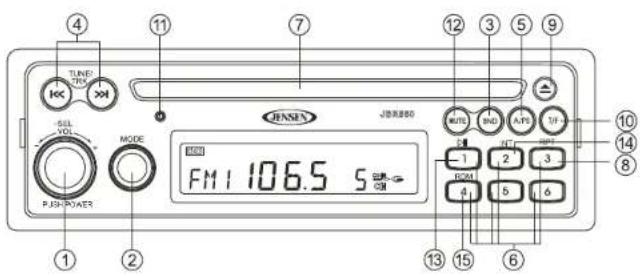
TUNES VOL MODE PUSH-POWER FM1 106.5 S Jitter filter port NOTE IND APS TIP 1 2 3 4 5 6 10 14 8Power On/ Off
Press the rotary encoder POWER button (1) to turn the unit on. Press and hold to turn the unit off. The unit will resume at the last mode selected (Tuner, Aux, etc.).
Volume Control
To increase the volume, turn the rotary encoder (1) to the right. To decrease the volume, turn the rotary encoder to the left. While adjusting the volume, the LCD displays a numerical representation of the level. The maximum volume setting is "63".
Mute
Press the MUTE button (12) on the control panel to mute the audio output. Press MUTE again to restore the audio output to the previous level.
Mode
Press the MODE button (2) on the control panel to select a different mode of operation, as indicated on the display panel. Available modes include Tuner (AM/FM), CD, and LINE (optional Auxiliary Input).
NOTE: CD mode will be skipped if no CD is inserted.
Reset
Use a ball point pen or thin metal object to press the RESET button (11). The reset button should be activated for the following reasons:
- initial installation of the unit when all wiring is completed
• function buttons do not operate
- error symbol on the display
Audio Menu
With the radio on, press the SEL button/rotary encoder (1) on the control panel to access the audio menu. You can navigate through the audio menu items by pressing the SEL button repeatedly. Once the desired menu item appears on the display, adjust that option by turning the rotary encoder within 5 seconds. The unit will automatically exit the audio menu after five seconds of inactivity. The following menu items can be adjusted.
BASS Level
Use the rotary encoder to adjust the Bass level range from "-7" to "+7".
TREBLE Level
Use the rotary encoder to adjust the Treble level range from "-7" to "+7".
Balance (BAL)
Use the rotary encoder to adjust the Balance between the left and right speakers from "L15" (full left) to "R15" (full right).
Fader (FAD)
Use the rotary encoder to adjust the Fader between the rear and front speakers from "R15" (full rear) to "F15" (full front).
LOUD
Use the rotary encoder (1) to turn the LOUD feature "on" or "off". "Off" is the default setting.
Auxiliary Input (LINE)
To access an auxiliary device:
-
Connect the portable audio player to the AUX IN input cables on the back of the radio.
-
Press the MODE button (2) to select LINE mode. "LINE" will appear on the display.
-
Press MODE again to cancel LINE mode and go to the next mode.
PA Operation (microphone sold separately)
- Connect the PA Microphone with a 4-PIN connector to the 4-PIN socket on the rear of the unit.
- The unit will automatically switch to PA mode when the Mic switch is pushed "ON".
• The PA output level can be adjusted using the rotary volume encoder (1).
- With radio power off, the radio will wake up when PA mic is keyed to make an announcement. Please note that it will take a few seconds before the radio "wakes up" and PA is active. Radio will return to the off state when the PA mic is released.
Liquid Crystal Display (LCD)
The current frequency and activated functions are shown on the LCD panel.
NOTE: LCD panels may take longer to respond when subjected to cold temperatures for an extended period of time. In addition, the visibility of the numbers on the LCD may decrease slightly. The LCD display will return to normal when the temperature increases to a normal range.
Time/ Frequency Display Selector (T/ F)
Displaying the Clock
Press the T/F button (10) to display the time of the incorporated quartz clock for 5 seconds.
Setting the Clock
- To set the clock, first turn the vehicle ignition and radio on.
- Press and hold the T/F button (10).
- Press the TUNE/TRK |<< and >>| buttons (4) to adjust the hours. "AM" or "PM" will appear on the display to indicate AM or PM.
- Press the T/F button again to move the cursor to the minutes position, and then use the TUNE/TRK |<< and >>| buttons to adjust the minutes.
- After five seconds, normal operation will resume.
TUNER OPERATION
Select a Band
Press the BND button (3) to change between three FM bands and two AM bands.
- During FM operation, when the station is broadcasting in stereo, the stereo icon ( ) ① appears on the display.
- During AM operation, no indications are displayed.
Manual Tuning
Press the TUNE/TRK >>| or |<< buttons (4) to manually step tune to the next or previous frequency.
Auto Seek Tuning
Press and hold the TUNE/TRK >>| or |<< buttons (4) to automatically seek the next strong station.
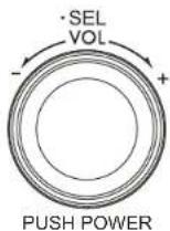
Preset Stations
Six numbered preset buttons store and recall stations for each band.
Store a Station
Select a band (if needed), then select a station. Press and hold a preset button (6) for two seconds. The preset number will appear on the LCD.
Recall a Station
Select a band (if needed). Press a preset button (6) to select the corresponding stored station.
text_image
TUNE VOL MODE FM1 106.5 5 JUNEN JUNEN300 NOTEL RND APS TO -1 2 3 4 5 6 10 14 8 13 15 6Automatically Store / Preset Scan (A/PS)
Automatically Store
Select an AM or FM band. Press and hold the A/PS button (5) for more than 2 seconds to automatically select six strong stations and store them in the current band. The new stations replace any stations already stored in that band. This feature is most useful when traveling in a new area where you are not familiar with the local stations.
Preset Scan
Select a band. Press A/PS (5) to scan stations stored in the current band. The unit will pause for 5 seconds at each preset station. Press A/PS again to stop scanning when the desired station is reached.
CD PLAYER OPERATION
Inserting and Ejecting a Disc
Insert a disc, label-side up, into the disc slot (7). The unit will automatically draw the disc in and play the first track on the disc, whether the power was turned on or not.
Press the eject ▲ button (9) to stop disc play and eject the disc. The unit will revert to radio operation.
If an ejected disc is not removed within 10 seconds, it will automatically be reloaded to prevent damage to the CD (CD-IN icon appears on the display panel).
text_image
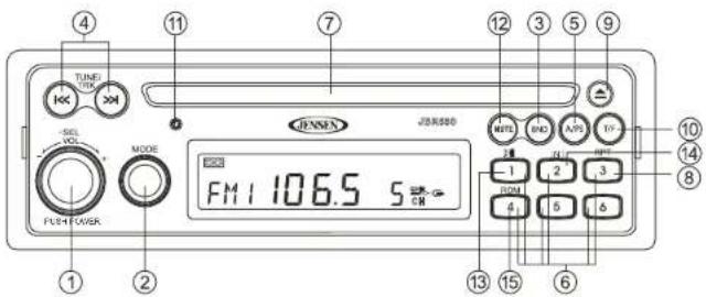
TUNG VOUT JENSEN MODE FM1 106.5 S PLR POWER ① ② ④ ⑦ ⑬ ③ ⑤ ⑨ ⑩ ⑭ ⑮ ⑯ ⑪ ⑫ ⑬ ⑭ ⑮ ⑯ ⑰ ⑱ ⑲ ⑳ ㉑ ㉒ ㉓ ㉔ ㉕ ㉖ ㉗ ㉘ ㉙ ㉚ ㉛ ㉜ ㉝ ㉞ ㉟ ㉳ ㉟ ㉟ ㉟ ㉟ ㉟ ㉟ ㉟Controlling Disc Playback
Selecting Tracks
Press the TUNE/TRK >>| or |<< button (4) to advance to the next track on the disc. The selected track number will appear on the display.
Fast Forward/Fast Reverse
Press and hold the TUNE/TRK >>| or |<< button (4) to fast forward or fast reverse through the disc. Disc play starts when the button is released.
Play/Pause Disc Playback
Press the 1/>|| button (13) to pause disc play. The display will flash while paused. Press the 1/>|| button again to resume disc Play.
Previewing Tracks (Intro)
Press the 2/INT button (14) to play the first 10 seconds of each track sequentially. Press 2/INT again to stop Intro Scan and resume normal play at the current track.
Repeat Play
- Press the 3/RPT button (8) during disc play to repeat play the current track.
- Press 3/RPT again to stop repeat play.
Random Play
- Press the 4/RDM button (15) during disc play to play all tracks in random, shuffled order. - Press 4/RDM again to stop random play.
JENSEN
JBR550
CARE AND MAINTENANCE
- Keep the product dry. If it does get wet, wipe it dry immediately. Liquids might contain minerals that can corrode the electronic circuits.
- Keep the product away from dust and dirt, which can cause premature wear of parts.
- Handle the product gently and carefully. Dropping it can damage circuit boards and cases, and can cause the product to work improperly.
- Wipe the product with a dampened cloth occasionally to keep it looking new. Do not use harsh chemicals, cleaning solvents, or strong detergents to clean the product.
- Use and store the product only in normal temperature environments. High temperature can shorten the life of electronic devices, damage batteries, and distort or melt plastic parts.
Ignition
The most common source of noise in reception is the ignition system. This is a result of the radio being placed too close to the ignition system (engine). This type of noise can be easily detected because it will vary in intensity of pitch with the speed of the engine.
Usually, the ignition noise can be suppressed considerably by using a radio suppression type high voltage ignition wire and suppressor resistor in the ignition system. (Most vehicles employ this wire and resistor but it may be necessary to check them for correct operation.) Another method of suppression is the use of additional noise suppressors. These can be obtained from most professional mobile electronics retailers.
Interference
Radio reception in a moving environment is very different from reception in a stationary environment (home). It is very important to understand the difference.
AM reception will deteriorate when passing under a bridge or when passing under high voltage lines. Although AM is subject to environmental noise, it has the ability to be received at great distance. This is because broadcasting signals follow the curvature of the earth and are reflected back by the upper atmosphere.
TROUBLESHOOTING
| Symptom Cause | Solution | |
| No power The vehicle's accessory switch is not on | If the power supply is properly connected to the vehicle's accessory terminal, switch the ignition key to "ACC". | |
| Disc cannot be loaded or ejected | Presence of CD disc inside the player | Remove the disc in the player and insert the new one. |
| Inserting the disc in reverse direction | Insert the compact disc with the label facing upward. | |
| Compact disc is extremely dirty or disc is defective | Clean the disc or try to play a new one. | |
| Condensation Leave the player off for an hour or so, then try again. | ||
| No sound Volume is too low | Adjust volume to audible level. | |
| Wiring is not properly connected. | Check wiring connections. | |
| The operation keys do not work | Control panel not properly installed | Reinstall control panel. |
| The built-in microcomputer is not operating properly due to noise | Press the RESET button. | |
| Sound skips The installation angle is more than 30 degrees. | Adjust the installation angle to less than 30 degrees. | |
| Cannot tune to radio station, auto-seek does not work | The disc is dirty or defective. | Clean the disc and try to play again or use new disc. |
| The antenna cable is not connected. | Insert the antenna cable firmly. | |
| The signals are too weak. Select a station manually. | ||
SPECIFICATIONS
CD
Signal to Noise Ratio. ≥ 55 dB
Channel Separation ....: More than 50 dB
Frequency Response : 20 Hz - 20 kHz
FM Radio
Frequency Coverage 87.5 to 107.9 MHz
Sensitivity (S/N=30dB) 4μV
Image Rejection ....>45 dB
Stereo Separation ....>25 dB
AM/MW
Frequency Range 530-1710 kHz
Sensitivity (S/N=20dB) 36 dB
General
Operating Voltage ....DC 12 Volts
Grounding System ...... Negative Ground
Speaker Impedance 4-8 ohms per channel
Tone Controls:
Bass (at 100 Hz) : ±10 dB
Treble (at 10 kHz)....:±10 dB
Power Output 40W x 4
Current Drain.... 10 Amp (max.)
Dimensions 183mm (W) x 158mm (D) x 58mm (H)

text_image
ASA electronics THE MOBILE ELECTRONICS COMPANY SINCE 1977ASA Electronics Corporation
www.asaelectronics.com
© 2010 ASA Electronics Corporation
v.121709