XA4300 - Radio JENSEN - Free user manual and instructions
Find the device manual for free XA4300 JENSEN in PDF.

| Product Type | AM/FM Radio |
| Brand | Jensen |
| Model | XA4300 |
| Dimensions (HxWxD) | 5.5 x 10 x 6 inches |
| Weight | 2.5 lbs |
| Power Supply | AC 110-120V 60Hz or 4 D batteries (not included) |
| Frequency Range | FM 88-108 MHz, AM 530-1710 kHz |
| Output Power | 2W RMS |
| Speaker | 4-inch full-range |
| Antenna | Built-in FM dipole, AM ferrite |
| Controls | Volume, tuning, band selector, power |
| Display | Analog tuner dial |
| Aux Input | 3.5mm stereo jack |
| Headphone Jack | 3.5mm stereo |
| Clock | Analog clock with alarm |
| Wake Function | Alarm to radio or buzzer |
| Sleep Timer | Yes, up to 60 minutes |
| Maintenance | Wipe with dry cloth, keep away from moisture |
| Safety | Do not expose to water or open the device |
| Spare Parts | Contact manufacturer for replacement parts |
| Manual | Available for download in PDF format |
Frequently Asked Questions - XA4300 JENSEN
User questions about XA4300 JENSEN
0 question about this device. Answer the ones you know or ask your own.
Ask a new question about this device
Download the instructions for your Radio in PDF format for free! Find your manual XA4300 - JENSEN and take your electronic device back in hand. On this page are published all the documents necessary for the use of your device. XA4300 by JENSEN.
USER MANUAL XA4300 JENSEN
Amplifier Installation and Operation
text_image
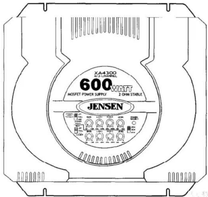
XA4300 4/3-L CHANNEL 600WATT MOSFET POWER SUPPLY 2 OHM STABLE JENSEN Power Resistors 1.0V 1.5V 2.0V 2.5V 3.0V 3.5V 4.0V 4.5V 5.0V 5.5V 6.0V 6.5V 7.0V 7.5V 8.0V 8.5V 9.0V 9.5V 10.0V 10.5V 11.0V 11.5V 12.0V 12.5V 13.0V 13.5V 14.0V 14.5V 15.0V 15.5V 16.0V 16.5V 17.0V 17.5V 18.0V 18.5V 19.0V 19.5V 20.0V 20.5V 21.0V 21.5V 22.0V 22.5V 23.0V 23.5V 24.0V 24.5V 25.0V 25.5V 26.0V 26.5V 27.0V 27.5V 28.0V 28.5V 29.0V 29.5V 30.0V 30.5V 31.0V 31.5V 32.0V 32.5V 33.0V 33.5V 34.0V 34.5V 35.0V 35.5V 36.0V 36.5V 37.0V 37.5V 38.0V 38.5V 39.0V 39.5V 40.0V 40.5V 41.0V 41.5V 42.0V 42.5V 43.0V 43.5V 44.0V 44.5V 45.0V 45.5V 46.0V 46.5V 47.0V 47.5V 48.0V 48.5V 49.0V 49.5V 50.0V 50.5V 51.0V 51.5V 52.0V 52.5V 53.0V 53.5V 54.0V 54.5V 55.0V 55.5V 56.0V 56.5V 57.0V 57.5V 58.0V 58.5V 59.0V 59.5V 60.0V 60.5V 61.0V 61.5V 62.0V 62.5V 63.0V 63.5V 64.0V 64.5V 65.0V JENSENIntroduction
Thank you for purchasing a Jensen amplifier. The XA series amplifiers offer extreme value and performance. Proper installation is essential for optimal performance and long-term reliability. Please read through this manual first to familiarize yourself with your amplifier and its functions.
Warranty Service
If your Jensen amplifier should ever require service, you will need to have the original dated receipt. If you ever need to return the unit for any reason, always include the receipt with the product.
Installation Assistance
M - F 8:00 am to 6:00 pm EST @ 1.800.323.0221
365 / 24 / 7 @ www.jensenaudio.com
Contents
Features 3
Installation.... 3
Before You Begin 3
Disconnect Battery 3
Supplies and Tools Needed ....3
Location and Mounting 4
Routing Wires....4
Wiring 5
Power 5
Power Terminal (+12V) 5
Ground Terminal (GND) 5
Remote Terminal (REM) 5
Fuses 5
Inputs, RCA Output, Remote Level Control ....6
Input Wiring 6
Remote Level Control (XA4300) 7
Connecting Other Amps 7
Speaker Wiring Options 8
Indicators and Controls 10
Crossover (X-OVER) 10
Power/Protect Light 10
2CH / 3CH / 4CH .... 11
Level....12
Bass 12
Testing 12
Reconnect Battery 12
Test Power Wiring 12
Test Speaker Connections 12
Troubleshooting.... 13
Specifications 14
Warranty 15
Features
XA Series 4-channel amplifiers include:
- Easy access top mounted controls
• Continuously variable high pass/low pass crossover - 40Hz – 400Hz crossover frequency range
• Crossover mode selector switch
• Continuously variable bass boost, centered at 45Hz - Input level control
-
Remote level control (XA4300)
-
Traditional input circuitry – low and high level inputs
• Pre-amp output for installation flexibility
• Dual status LED diagnostic indicator
• Thermal, short circuit and low impedance protection circuitry
• PWM MOSFET power supply - Discrete amplifier design with complementary high current Bi-polar output stage
Installation
Before You Begin
Before you begin, you will need tools, supplies and adapters. It is best to make sure you have everything you need before you start.
Disconnect Battery
Before you begin, always disconnect the battery negative terminal.
Supplies and Tools Needed
Supplies
- Black electrical tape
- Amplifier Installation Kit
Tools
• Cordless drill with assortment of bits
• Flat and Phillips screwdrivers
- Wire cutters/strippers
- Crimping tool
• 12-volt test light or digital multimeter
- Wire brush, sandpaper or scraping tool (ground connection to vehicle should be a clean, unpainted metal surface)
Location and Mounting
The XA amplifier's compact design allows greater flexibility in mounting. It can be mounted under a seat or in the trunk.
When selecting a location, remember that amplifiers generate heat. Select a location where air can circulate around the amplifier. Do not cover the amplifier with carpets or enclose it behind interior trim panels. Do not mount the amplifier in an inverted or upside down configuration. Every installation will be a bit different based upon vehicle design.
Check all locations and placements carefully before making any cuts or connections.
Important
Allow air circulation around the amplifier.
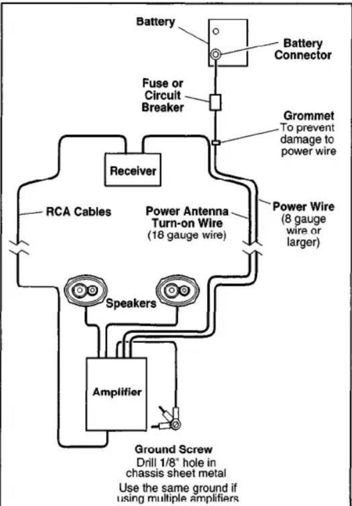
Routing Wires
flowchart
graph TD
    A["Battery"] --> B["Battery Connector"]
    B --> C["Fuse or Circuit Breaker"]
    C --> D["Receiver"]
    D --> E["RCA Cables"]
    D --> F["Power Antenna Turn-on Wire (18 gauge wire)"]
    D --> G["Power Wire (8 gauge wire or larger)"]
    E --> H["Speakers"]
    F --> I["Amplifier"]
    G --> J["Ground Screw Drill 1/8" hole in chassis sheet metal Use the same ground if using multiple amplifiers"]
    style A fill:#f9f,stroke:#333
    style B fill:#ccf,stroke:#333
    style C fill:#cfc,stroke:#333
    style D fill:#fcc,stroke:#333
    style E fill:#cff,stroke:#333
    style F fill:#ffc,stroke:#333
    style G fill:#fcc,stroke:#333
    style H fill:#ffc,stroke:#333
    style I fill:#ffc,stroke:#333
    style J fill:#ffc,stroke:#333
Important
If wiring connections are made wrong, the unit will not operate properly and it could be damaged. Follow the installation instructions carefully, or have the installation handled by an experienced technician.
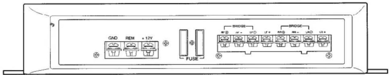
Wiring
Power
text_image
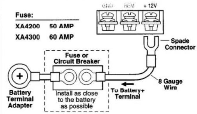
GND REM + 12V FUSE BRIDGE BRIDGE BRIDGE BRIDGE BRIDGE BRIDGE BRIDGEPower Terminal (+12V)
Connect directly to the vehicle battery+ terminal with 8 gauge wire (minimum).
text_image
Fuse: XA4200 50 AMP XA4300 60 AMP Spade Connector 8 Gauge Wire To Battery+ Terminal Battery Terminal Adapter Fuse or Circuit Breaker Install as close to the battery as possibleNote:
This amplifier will only work with 12-volt systems.
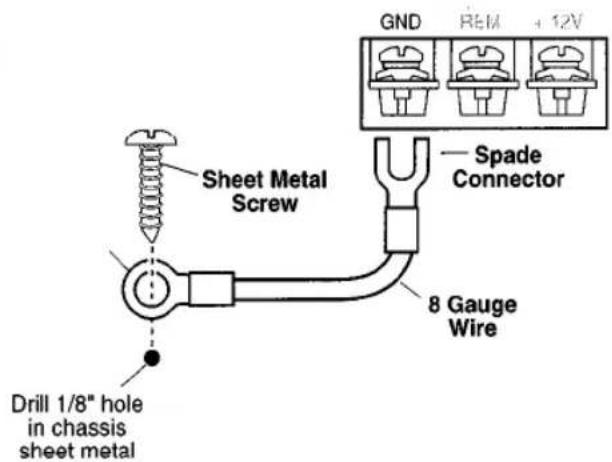
Ground Terminal (GND)
Connect to a good chassis ground. The ground connection should be to clean, unpainted metal to provide a good electrical connection.
text_image
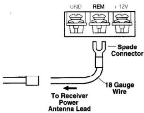
GND REM +12V Sheet Metal Screw Spade Connector 8 Gauge Wire Drill 1/8" hole in chassis sheet metalRemote Terminal (REM)
Connect the power antenna/amplifier turn-on lead from the receiver to the AMPLIFIER REMOTE terminal.
text_image
GND REM + 12V Spade Connector 18 Gauge Wire To Receiver Power Antenna LeadFuses
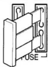
Use only blade-type fuses.
Fuse:
XA4200 25 AMP
XA4300 30 AMP
Inputs, RCA Output, Remote Level Control
text_image
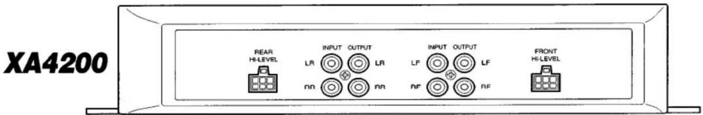
XA4200 REAR HI-LEVEL INPUT OUTPUT LR LR INPUT OUTPUT LF LF RF RF FRONT HI-LEVEL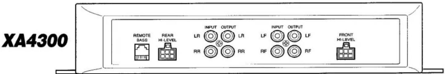
text_image
XA4300 REMOTE BASS REAR HI-LEVEL INPUT OUTPUT LR LR INPUT OUTPUT LF LF RF RF FRONT HI-LEVELInput Wiring
Low Level Input (RCA Input)
Low level (RCA) input is preferred for best performance. Most trunk/hatchback installations will require a 15-20 foot RCA cable. While pick-up trucks and under-seat mounting will require a 6-10 foot RCA cable. Connect an RCA cable from your receiver to the RCA input on your amplifier.
High Level Input
High level input should be used when an RCA output is not available from the receiver. Connect the speaker outputs from the receiver to the high level input connector.
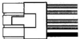
White = Left (+) White/Black = Left (−) Gray = Right (+) Gray/Black = Right (−) Black (ground)
text_image
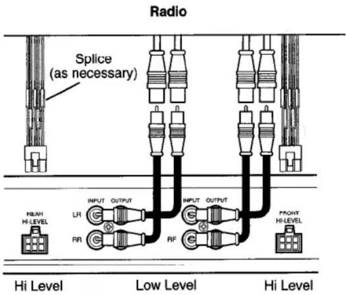
Radio Splice (as necessary) NEAH HI-LEVEL INPUT OUTPUT LR RR RF INPUT OUTPUT RF HI Level Low Level HI Level FRONT HI-LEVELImportant
Only connect the low (RCA) or high level input. Do not use both at the same time.
Remote Level Control – Rear Speakers (XA4300)
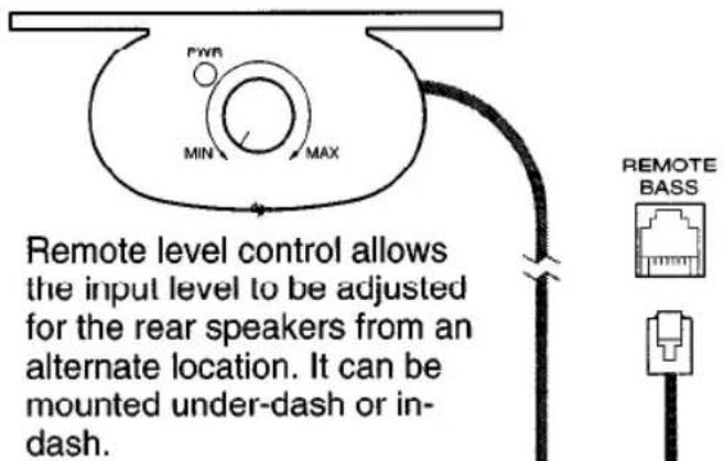
text_image
FWR MIN MAX Remote level control allows the input level to be adjusted for the rear speakers from an alternate location. It can be mounted under-dash or in-dash. REMOTE BASSWhen the amplifier is used to drive subwoofers, and the low pass crossover is activated, the remote level control can be used as a "remote bass level control". This enables you to control the bass level, independent from the rest of the system. This is convenient for system tuning and/or when playing many different types of music.
Connecting other Amps
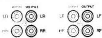
text_image
OUTPUT LR C LRL RR OUTPUT LF O O LF HF C RFRCA Output
The "output" signal allows you to conveniently connect other amplifiers to each other.
Speaker Wiring Options
4 Speakers
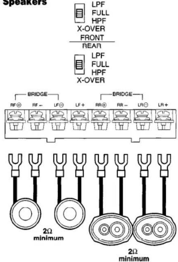
text_image
Speakers LPF FULL HPF X-OVER FRONT REAR LPF FULL HPF X-OVER BRIDGE RF⊕ RF- LF⊕ LF+ BR⊕ AR- LR⊖ LR+ BRIDGE 2Ω minimum 2Ω minimum2 Speakers + Bridged Subwoofer
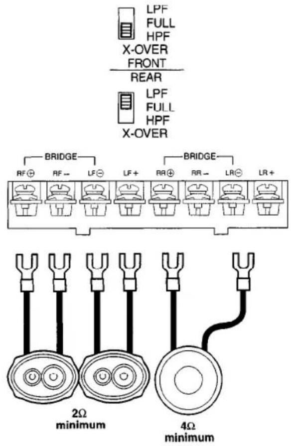
text_image
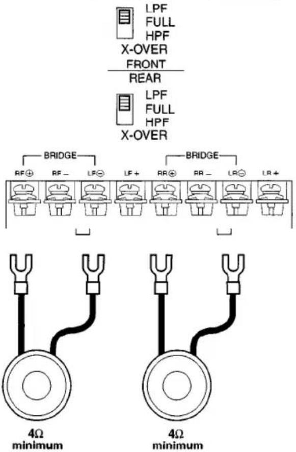
LPF FULL HPF X-OVER FRONT REAR LPF FULL HPF X-OVER BRIDGE RF⊕ RF- LF⊖ LF+ LR⊕ LR- LR- LR+ BRIDGE LR⊕ LR- LR- LR+ 2Ω minimum 4Ω minimum2 Subwoofers/Bridged Mono (XA4200)
text_image
LPF FULL HPF X-OVER FRONT REAR LPF FULL HPF X-OVER BRIDGE RF⊕ RF- LF⊖ LF+ RR⊕ RR- LR⊖ LR+ BRIDGE 4Ω minimum 4Ω minimum4 Speakers + 2 Subwoofers
text_image
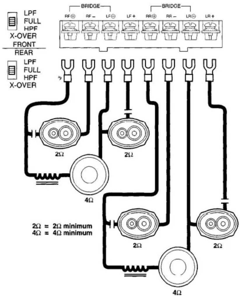
LPF FULL HPF X-OVER FRONT REAR LPF FULL HPF X-OVER BRIDGE RF⊕ RF- LF⊖ LF+ RR⊕ RR- LR⊖ LR+ 2Ω 2Ω 2Ω 2Ω 2Ω 4Ω 2Ω = 2Ω minimum 4Ω = 4Ω minimumImportant
When running a subwoofer and two full-range speakers together (Tri-mode operation), high and low pass filters must be used. Failure to install these filters may damage your amp and/or speakers.
| Freq. Hz | Speaker Impedance | |||||
| 2 OHMS | 4 OHMS | 8 OHMS | ||||
| L | C | L | C | L | C | |
| 80 | 4.1mH | 1000μF | 8.2mH | 500μF | 15mH | 250μF |
| 100 | 3.1mH | 800μF | 6.2mH | 400μF | 12mH | 200μF |
| 130 | 2.4mH | 600μF | 4.7mH | 300μF | 10mH | 150μF |
| 200 | 1.6mH | 400μF | 3.3mH | 200μF | 6.8mH | 100μF |
| 250 | 1.2mH | 300μF | 2.4mH | 150μF | 4.7mH | 75μF |
| 400 | .8mH | 200μF | 1.6mH | 100μF | 3.3mH | 50μF |
| 600 | .5mH | 136μF | 1.0mH | 68μF | 2.0mH | 33μF |
| 800 | .41mH | 100μF | .82mH | 50μF | 1.6mH | 26μF |
| 1000 | .31mH | 78μF | .62mH | 39μF | 1.2mH | 20μF |
| 1200 | .25mH | 66μF | .51mH | 33μF | 1.0mH | 16μF |
| 1800 | .16mH | 44μF | .33mH | 22μF | .68mH | 10μF |
| 4000 | .08mH | 20μF | .16mH | 10μF | .33mH | 5μF |
| L | C |
| Inductor | Capacitor |
Indicators and Controls
text_image
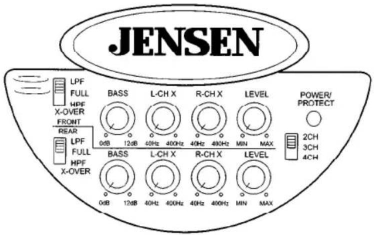
JENSEN LPF FULL HPF X-OVER FRONT REAR 0dB 12dB BASS L-CH X R-CH X LEVEL POWER/ PROTECT 40Hz 400Hz 40Hz 400Hz MIN MAX LPF FULL HPF X-OVER BASS L-CH X R-CH X LEVEL 2CH 3CH 4CH 0dB 12dB 40Hz 400Hz 40Hz 400Hz MIN MAXCrossover (X-OVER)
Adjust the crossover to accommodate your chosen installation method.
text_image
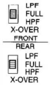
LPF FULL HPF X-OVER FRONT REAR LPF FULL HPF X-OVER- LPF-(low pass filter) Select this filter when the amplifier will be driving woofers or subwoofers.
- FULL-Crossover is not active, amplifier is in "full range" mode.
- HPF-(high pass filter) Select this filter when the amplifier will be driving full range/separate speakers, and you want to limit the "bass" going to these speakers.
Tri-mode/Three channel operation
An amplifier is usually configured for tri-mode operation when you want to use one amplifier to drive a pair of front speakers and subwoofer(s). In other words, when you want drive a complete system with one amp. Your Jensen amplifier is capable of tri-mode operation.
Important
Tri-mode operation requires using "passive crossovers". These crossovers are available at your local retailer or install shop. Failure to install these filters may damage your amplifier and/or your speakers.
Power / Protect Light
POWER/ PROTECT

A dual status LED indicator illuminates red or green to indicate the status of the amplifier.
Green – Power applied, ON
Red - Protection circuit activated, STANDBY
2CH/3CH/4CH
The XA4200/XA4300 can be configured for three different input modes: 4 channel, 3 channel or 2 channel.
4 Channel
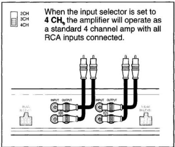
text_image
When the input selector is set to 4 CH₆ the amplifier will operate as a standard 4 channel amp with all RCA inputs connected. 2CH 3CH 4CH INPUT OUTPUT INPUT OUTPUT INPUT OUTPUT IN LEVEL3 Channel
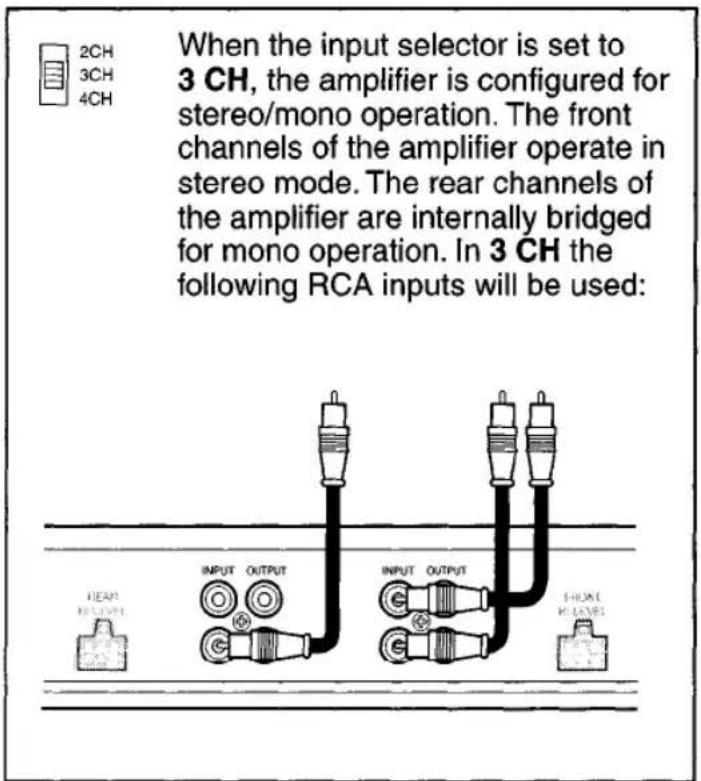
text_image
When the input selector is set to 3 CH, the amplifier is configured for stereo/mono operation. The front channels of the amplifier operate in stereo mode. The rear channels of the amplifier are internally bridged for mono operation. In 3 CH the following RCA inputs will be used:2 Channel
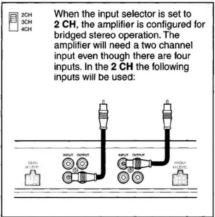
text_image
When the input selector is set to 2 CH, the amplifier is configured for bridged stereo operation. The amplifier will need a two channel input even though there are four inputs. In the 2 CH the following inputs will be used: 1 2CH 3CH 4CH INPUT OUTPUT INPUT OUTPUT FLASH IN LEVEL OUTPUT PROXT IN LEVEL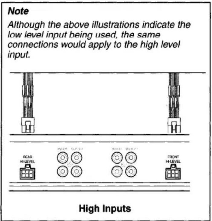
text_image
Note Although the above illustrations indicate the low level input being used, the same connections would apply to the high level input. REAR HI-LEVEL INDUCE AUXEER INDUCE QUICKER FRONT HI-LEVEL High InputsLevel
text_image
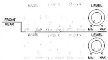
FRONT REAR BASS 1-CHX 2-CHX LEVEL MIN MAX BASS 1-CHX 2-CHX LEVEL MIN MAXThe input level control matches the output of your radio to the input of the amplifier. After the installation is complete, make sure the input level control on the amp is turned down all the way (counterclockwise or all the way to the left). Play a tape or CD (make sure bass and treble settings or EQ are flat too) and turn the volume up slowly until you just start to hear distortion. Now back the volume down just a bit. On the amp, slowly turn up the input level control (clockwise or to the right) until you just start to hear distortion and back it down a bit. Now your radio and amplifier levels are matched.
Bass
text_image
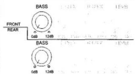
BASS FRONT REAR 0dB 124B BASS 0dB 124BBASS increases the volume of the bass at 45Hz by up to 12 db.
Use very carefully!
Testing
Before you finish the installation, you should do the following tests to make sure the wiring is correct and everything is operating properly.
Reconnect Battery
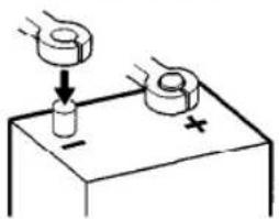
When wiring is complete, reconnect the battery negative terminal.
text_image
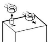
Diagram showing a hand pressing down on a cylindrical object with a plus sign, illustrating a physics or engineering concept.Test Power Wiring
-
Turn on the receiver but do not turn up the volume. The amplifier power light should come on. If not, check the REM and +12V wires.
-
Turn up the receiver volume slightly. All speakers should operate. If not, check wiring connections at amplifier and speakers.
Test Speaker Connections
These tests make sure the speakers are connected right. If speakers don't play at all, one (or both) speaker wires may be disconnected. If the wrong speaker plays (you hear left speaker when you expect right speaker) make sure you connected the wires correctly.
Troubleshooting
| Problem | Possible Cause | Corrective Action |
| Amplifier does not operate (power LED not on) when vehicle and radio are on | No power to +12V terminal | Repair wire or connections. |
| No power to remote wire with radio on | Check connections to radio with test light. | |
| Fuse blown | Check fuse. | |
| Radio volume needs to be turned up too high for amp to work | Input level control adjusted too low | Adjust input level control. |
| Radio volume is too sensitive | Input level control adjusted too high | Adjust input level control to lower setting. |
| Sound from only one speaker | Defective speaker | Replace speaker. |
| Poor connections to speaker (wire) | Check connections. | |
| RCA input cable defective | Replace cable. | |
| Input level control adjusted too high | Adjust input level control. | |
| Sound distorted | Speaker wires shorting together | Separate speaker wires and insulate. |
| Blows fuses | Power wires hooked up incorrectly | Check power wire connections. |
| Speakers blown or defective | Check speakers. | |
| Engine noise (Ignition noise/static or Alternator whine) | Improper ground connections Ground loop(s) | Reroute RCA away from main power wires. |
| Reroute RCA cable. | ||
| Make sure amp is grounded to a clean, solid part of the chassis/frame. | ||
| Protect light comes on/ amplifier shuts down | Amp is in thermal protection | Let amp cool down before attempting to turn back on (some installations may require a fan to keep the amp cool, especially if you are driving subwoofers with the amp). |
| Faulty speaker connection and/or crossover | Check speakers and/or crossovers for loose or bad connections. | |
| Low battery voltage | Make sure you are getting between 10.8-15.6 volts to the amplifier with a digital multimeter measured at the amplifier. | |
| Speaker impedance less than 2 ohms per channel | If you are using 4 ohm speakers you cannot have more than two speakers wired in parallel per channel. Amp will not operate into 2 ohms bridged. | |
| No output on channels | Speaker wires not connected to speakers properly | Refer to pages 6-9 for proper installation. |
| Input hooked up incorrectly |
Specifications
XA Series 4-Channel Amplifiers
Frequency Response 20 Hz-20 kHz ± 0.5 dB
Signal to Noise Ratio @ Rated Power ....>100 dB
Channel Separation @ Ref. Power ....>65 dB, 1 kHz
THD & IMD @ Ref. Power into 2 ohms ....<0.8%
Speaker Impedance 2-8 ohms
Input Impedance 47 k ohms
Bass Boost Center Frequency 45Hz
Crossover 12 dB/octave, Butterworth
Power Requirement 14.4 VDC (10.8-15.6 VDC allowable)
XA4200
Power output @ 14.4 VDC, 20-20 kHz
(4 ohms) 50 Watts per channel RMS, < 0.5% THD
(2 ohms) 75 Watts per channel RMS, < 0.8% THD
(4 ohms) bridged 150 Watts per channel RMS, < 0.8% THD
Dimensions 3" x 11.125" x 10" (76mm x 283mm x 254mm)
XA4300
Power output @ 14.4 VDC, 20-20 kHz
(4 ohms).... Front: 50 Watts per channel RMS, < 0.5% THD
Rear: 100 Watts per channel RMS, < 0.5% THD
(2 ohms).... Front: 75 Watts per channel RMS, < 0.8% THD
Rear: 150 Watts per channel RMS, < 0.8% THD
(4 ohms) bridged.... Front: 150 Watts per channel RMS, < 0.8% THD
Rear: 300 Watts per channel RMS, < 0.8% THD
Dimensions 3" x 11.125" x 13" (76mm x 283mm x 330mm)
Specifications subject to change without notice.
Limited One Year Warranty- USA and Canada
Length of Warranty. This warranty from Recoton Mobile Electronics shall be in effect for a period of one year from the date of the first consumer purchase.
Persons Protected. This warranty will be enforceable by the original owner and any subsequent owners during the warranty period so long as proof of date of purchase from an authorized Jensen dealer is presented whenever warranty service is required.
What is Covered. Except as otherwise specified below, this warranty covers all defects in material and workmanship in this product. The following are not covered: damage resulting from accident, misuse, abuse, neglect, product modification, improper installation, incorrect line voltage, unauthorized repair or failure to follow instructions supplied with the product; damage occurring during shipment (claims must be presented to the carrier); elimination of car static or other electrical interferences; any product purchased outside USA or Canada, or on which the serial number has been defaced, modified or removed.
How You Can Get Service.
U.S. Purchasers. Please telephone Jensen at 1-800-323-4815. We will either inform you of the name and address of an authorized Jensen repair station which will service the product or will advise you to send the product to a factory service center.
Canadian Purchasers. The product should be returned to the Jensen dealer from whom it was purchased and such dealer either will service or arrange for service of the product.
If shipment of the product is required, it should be packed securely. The original dated bill of sale must always be included with the product as proof of warranty coverage.
What We Will Pay For. We will pay for all labor and material expenses required to repair the product, but you must pay any labor costs for the removal and/or installation of the product. If the product is shipped for warranty service, you must prepay the initial shipping charges, but Jensen will pay the return shipping charges if the product is returned to an address inside the USA or Canada.
Exclusion of Certain Damages. Jensen's liability is limited to the repair or replacement, at our option, of any defective product and shall not include incidental or consequential economic damages of any kind.
Some states and/or provinces do not allow limitations on how long an implied warranty lasts and/or do not allow the exclusion or limitation of incidental or consequential damages, so the above limitations and exclusions may not apply to you.
This warranty gives you specific legal rights, and you may also have other rights which vary from state to state and province to province.
JENSEN®
Recoton Mobile Electronics
A Division of Recoton Audio Corporation
A RECOTON® COMPANY
1090 Emma Oaks Trail
Lake Mary, Florida 32746
©2001 Recoton Audio Corporation
NOTES
CONSUMER INFORMATION CARD
IMPORTANT: Please see inside
JENSEN®
Please send other correspondence to:
Jensen
Customer Service
2950 Lake Emma Road
Lake Mary, FL 32746
or call 1-800-323-4815

First-Class
Postage
Required
Post Office will not deliver
without proper postage.
ELE019820
ERJ01-01
JENSEN®
P O BOX 17468
DENVER CO 80217-0468
1