
DG30025 - Instant water heater and boiler SIEMENS - Free user manual and instructions
Find the device manual for free DG30025 SIEMENS in PDF.


| Product Type | Instantaneous Water Heater and Boiler |
| Brand | Siemens |
| Model | DG30025 |
| Dimensions (H x W x D) | 450 x 300 x 250 mm |
| Weight | 12 kg |
| Power Supply | 230 V / 50 Hz |
| Power Consumption | 18 kW |
| Max Water Temperature | 65 °C |
| Min Flow Rate for Activation | 2.5 L/min |
| Functions | Instant water heating, temperature control, anti-freeze protection |
| Maintenance | Descaling every 6 months, clean inlet filter |
| Safety Features | Overheat protection, pressure relief valve, dry-run protection |
| Spare Parts | Heating element, thermostat, flow sensor |
| Warranty | 2 years |
Frequently Asked Questions - DG30025 SIEMENS
User questions about DG30025 SIEMENS
0 question about this device. Answer the ones you know or ask your own.
Ask a new question about this device
Download the instructions for your Instant water heater and boiler in PDF format for free! Find your manual DG30025 - SIEMENS and take your electronic device back in hand. On this page are published all the documents necessary for the use of your device. DG30025 by SIEMENS.
USER MANUAL DG30025 SIEMENS
Assembly and operating instructions
DG30025

1

2

natural_image
Diagram showing three 3D coordinate axes with cylindrical objects and a separate dot cluster, no text or symbols present.


flowchart
graph TD
    A["Input Port 11"] --> B["Control Block"]
    B --> C["Reservoir"]
    C --> D["Resistor"]
    D --> E["Diode"]
    E --> F["Output Port 12"]
    style A fill:#f9f,stroke:#333
    style B fill:#ccf,stroke:#333
    style C fill:#cfc,stroke:#333
    style D fill:#fcc,stroke:#333
    style E fill:#cff,stroke:#333
    style F fill:#ffc,stroke:#333


natural_image
Mechanical component diagram showing a rotating shaft and housing with bolt holes, labeled 'b', and an arrow indicating motion (no text or symbols beyond labels)
Eine Störung, was tun
This appliance is intended for domestic use or for household-based, non-commercial applications. Household-based applications include, e.g. usage in employees catering facilities for shops, offices, agricultural and other commercial operations, as well as usage by guests of guest houses, small hotels and similar residential establishments.
• Install and operate the appliance as described in the text and illustrations. We do not accept liability for damage resulting from failure to heed these instructions.
- This appliance is intended for use up to an altitude of 2000 m above sea level.
- The appliance may only be installed and stored in a frost-free room (due to residual water).

Risk of electric shock! If an fault occurs, immediately disconnect the plug from the power supply or turn off the mains voltage! Immediately shut off the cold water supply to the appliance should it leak.
- The appliance may only be connected and put into operation by qualified professional.
- To avoid potential sources of danger, repairs and maintenance may only be undertaken by a suitably qualified specialist.
- The statutory regulations of the respective country, as well as those of the local electricity and water suppliers, must be adhered to.
- If the power cord of this appliance is damaged, it must be replaced by the manufacturer, an authorised servicing agent or a similarly qualified person so as to avoid danger.
- The connection cable may not make contact with hot components. This can damage the insulation.
- Do not touch electrically live parts after installation.
- Shut off the water supply before connecting the appliance. Do not insert the plug into the mains socket or disconnect the power supply.
- Disconnect the power supply or turn off the mains voltage before opening the appliance.
- Connect the water supply first, circulate water through the appliance and then connect the electrical supply.
- Compliance with the IEC 60364-7-701 (DIN VDE 0100 Part 701) must be observed during installation of the appliance or the electrical accessories.
- No modifications to the appliance are permissible.
- This appliance can be used by children aged 8 years and older as well as by persons with diminished bodily, sensory or mental perception, or those who lack knowledge or experience, if they are monitored or have received instruction concerning use and comprehend the possible dangers that can result. Children may not play with the appliance. Cleaning and maintenance by the user may not be performed by unsupervised children.
- Keep children away from the appliance.
- Please monitor children to ensure that they do not play with the appliance.
- The mixer tap and the warm water pipe may be hot. Please inform and instruct children appropriately.
- Do not use aggressive or abrasive cleaning detergents!
- Do not use a steam cleaner.
- The appliance is only to be descaled by a suitably qualified specialist. Please observe the manufacturers warnings when decalcifying.
Closed water heater
- Only connect the appliance to a correctly earthed electrical socket. Do not use extension cables.
- Only a prototype-tested diaphragm safety valve may be installed.
- During the heating process, expansion water must drip out of the safety valve outlet.
The outlet pipe of the safety valve must remain open to the atmosphere. - The safety valve prevents excessive pressure from developing in the water heater during the heating process. Expansion water must be able to drain off via the safety valve.
- Do not block the outlet pipe!
- The size of the outlet pipe must suit the fully opened safety valve. The blow-off opening of the safety valve must remain open to the atmosphere.
- The blow-off pipe of the safety group must be installed with a constant decline in a frost-free room. Regular maintenance and operation of the safety valve are required to remove deposits and to ensure that the safety valve is not blocked.
- The installation instructions of the safety group must be followed.
- A shutoff valve must not be installed between the safety valve and the water heater.
- Supplied stickers: "For reasons of safety, water must come out of the outlet pipe during the heating period! Do not block!"— attach the stickers to the outlet pipe in a clearly visible position.
- The safety valve must be operated regularly to verify its function and to decalcify the valve.
Open outlet water heater
- The water heater is only suitable for use with an open (unpressurised) and a single tap connection. The warm water outlet is used for pressure compensation and may only be connected to suitable fittings (Order-No. BZ11114, BZ12411)
- The tap outlet must always remain free. Do not use perlators (diffusers) or shower taps.
- The instructions for unpressurised (open) water heaters that are used with a spray head must state that the spray head must be regularly cleaned and water scale removed.
- The installation instructions for unpressurised (open) water heaters must state that the water outlet must only be connected to the specified valves and fittings and NOT to any others.
For technicians only
Assembly Instructions
Mount the hot water wall storage unit as described in the diagram. Observe the instructions in the text. You will find the diagrams at the beginning of the manual.
Safety advice

Danger of electric shock!
In the case of a fault, disconnect the voltage supply.
Assembly
Assembly Preparation
Closed Operation
Mount close to the tap from which the most hot water will be extracted. A design proofed safety valve combination is to be installed. In addition, if water pressure exceeds 0.48 Mpa (4.8 bar), a pressure reducing valve is to be installed and adjusted accordingly. No shut-off valves may be installed between the safety modules and the reservoir. Discharge from the safety valve must always be open. The safety valve combination for closed operation must be accredited (design proofed):
Safety valve combination AK030300, i.e. safety valve combinations with pressure reducing valve AK040300 can be mounted
with a customary thermostat pre-mixer.
Note: According to the Energy Conservation Act, the temperature in the mains system must be limited to 60^ C for hot water pipes longer than 5m.
Open Operation
An appropriate overflow mix regulator is to be installed:
BZ12411 wall temperature regulator with bath spout, shower hose and hand sprinkler; or BZ11114 wall regulator with shower hose and hand sprinkler. The discharge from the fitting must always be free. Never use an aerator! A back-flow preventer is to be installed in the cold water intake.
Wall Assembly (page II, diagrams 3 to 10)
The assembly diagram is on the packaging. To allow for replacement of the heating flange and anti-corrosion anode, at least 350m of free space must be left underneath the reservoir. Use appropriate screws with a diameter of at least 12mm. Provide a special supporting structure for lightweight walls.
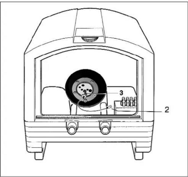
Unlock the safety bar (2) (shift the bar on the left e pull it down) remove the bracket. Pass the power line in its housing (3). Once mounted the appliance on the wall relock the bar 2.
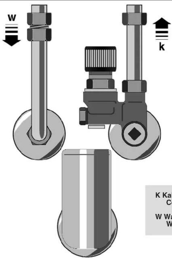
Water Connection (page III, diagrams 11)
Only detachable connections are permissible!
Before connecting the fittings, thoroughly flush out the water pipes in order to remove any impurities.
It is normal for water to trickle from the pressure safety device during the heating phase; for this reason, it is necessary to connect the outlet, which must always be left exposed to the atmosphere, to a drainage pipe that slopes downwards and located in an area not subject to ice.
Operating Modes
Single Power Operation
Connection without off-peak contact.
The appliance heats with the adjusted performance.
The 'fast-heating' button is only used for the reset and diagnose functions.
Connection with off-peak contact
If the 'fast-heating' button is activated, the device heats once to the configured temperature. Afterwards, the device turns itself off automatically.
Double Power Operation
Connection without off-peak contact.
The reservoir heats with the configured basic performance.
The "fast-heating function" activates a heating cycle at higher installed power in order to accelerate the heating-up procedure. To start this function, press the fast-heat button. The LED fast-heating' lights up. The function turns itself off automatically, as soon as the configured temperature has been reached. The LED 'fast-heating' turns off .
Connection with off-peak contact
During off-peak time the device heats with the configured basic performance. The "fast-heating function" activates a heating cycle at higher power in order to accelerate the heating-up procedure. To start this function, press the fast-heat button. The LED 'fast-heating' lights up. The function turns itself off again automatically as soon as the configured temperature has been reached. The LED fast-heating' turns off.
The rest of the time, the device does not heat. If the 'fast-heating' button is activated, the device heats once to the configured temperature. Afterwards, the device turns itself off automatically.
Boiler Mode
Connection without off-peak contact.
The device does not heat by default.
If the 'fast-heating' button is activated, the device heats once to the configured temperature. Afterwards, the device turns itself off automatically.
Electrical Connections

Danger of electric shock!
The power switch "S1" may only be activated in an unpowered state!!
Remove lower cap by taking the screws out (page V, diagram 15, 15.1, 15.2, 15.3).
Lead cable through the cable gland and cord grip and connect, then tighten the cable gland and cord grip (page IV, diagram 12-13).
Check that the system is suitable for the maximum power absorbed by the water heater (please refer to the data plate) and that the cross-section of the electrical connection cables is suitable, and no less than 1.5 mm^2 .
Operating mode
Set the power switch "S1" to the correct operating mode on the electronic board.
Set the desired load according to the connection examples.
| Power Switch “S1” | Mode of Operation | |||
 |  |  | Double power switch positions 5 / 6 / 7 | |
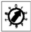 | 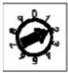 |  | 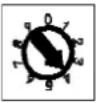 | Single power switch positions 1/ 2 / 3 / 4 |
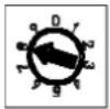 |  |  | Boiler mode switch positions 8 / 9 / 0 | |
The power switch is set by the manufacturer in position 5.
Double power
Depending on the home installation, the following connection variations are possible:
Refer to the connection types recommended for double power (page VI)
- Variant A, (page V, diagram 15):
If no low-tariff electricity is to be used, do not remove bridge between L1 and L1T.
- Variant B, (page V, diagram 15.1)
Connect the output of the autotimer (delivered by the electricity provider) with L1 and L1T.
- Variant C, (page V, diagram 15.2)
Connect switched phase L1T (connection for low-tariff power) to L1T terminal.
- Variant D, (page V, diagram 15.3)
Connect switched phase L1 to terminal L1 and L1T.

According to the duration of the off-peak period of either 8 or 4 hours, and the associated loads (refer to connection types on page V), set the power switch "S1" to the correct positions, 5 /6 / 7, of the double power set-up.
Single power
Depending on the home installation, the following connection variations are possible:
Refer to the connection types recommended for single power (page V)
Set power switch "S1" on the electronic board to positions 1 / 2 / 3 / 4 "single power".
Boiler mode
Depending on the home installation, the following connection variations are possible:
Refer to the connection types recommended for boiler switch (page V)
Set power switch "S1" on the electronic board to positions 8 / 9 / 0 "boiler mode".
Finally, separate the appropriate circuit diagram (E1/E2) and the corresponding power-switch position "S1" from the enclosed adhesive foil and adhere to the pad provided. Fill out the information decal about the installed circuit and installed load and adhere to the outside of the cover.
Initial Use
Important!
Fill the reservoir and flush it out until water discharges from all hot water taps, otherwise the temperature sensor and retainer will be damaged and require replacing.
During heating, displaced water must drop from the discharge of the safety valve (closed operation) or out of the mixer tap (open operation). Monitor the first heating cycle.
Maintenance
In order to avoid hazards, repairs may only be carried out by a customer service operator licensed by us.
The initial service through our customer service operator should take place around two years after the first operation. At this time, the device will potentially be decalcified. Afterwards, the customer service operator will recommend a date for the next service. Specify the E-No. and FD-No. when phoning the customer service operator!
Decalcification
Before decalcification the device must be emptied. Without placing stress on the device, draw hot water until cold water comes. Then, close the shut-off valve on the intake, open the hot water valves on all connected fittings and empty the device via the safety valve. A few litres of water will remain in the device. To empty completely, loosen the two screws on the cover and remove the cover (page IV, diagram 12). Unscrew the fastener “b” of the discharge connecting piece (page IV, diagram 14), the remaining water flows away.
Decalcify the device. The specially enamelled steel reservoir and the protection anode are not to come into contact with the decalcifier, do not work with a pump! Remove heater and de-calcify, clean discharge pipes mechanically and remove remaining lime.
In an open operation, a valve can be fitted between the fitting and cold water intake of the reservoir to aid emptying.
Technical data
| MODEL | |||
| Volume litres 30,0 | |||
| Weight when full kg 49 | |||
| Maximum operating pressure MPa (bar) 0,6 (6) | |||
| Degree of protection IP 25D | |||
| Water connection G1/2A | |||
| Time taken to heat to approx. 85 °C, Hours 1 kW 2,8 at a cold water supply temperature of 15 °C 2 kW 1,5 | |||
| 3 kW | 1 | ||
| MODEL | ||
| Energy class | D | |
| Load profile | S | |
| Power consumption yearly in kWh | (kWh) | 627 |
| Power consumption daily in kWh | (kWh) | 3,082 |
| Sound power level in dB | (dB) | 15 |
| Warm water efficiency in % | (%) | 29,4 |
| Mixing water | (I) | 53 |
| Double-power operationCurrent limits | 1/N/PE~230V | 1 - 3 kW 1/N/PE~230 V min 10 A // max 16 A2 - 3 kW 1/N/PE~230 V min 10 A // max 16 A | |
| Secure base load (min. xx A) | 2/N/PE~230V | 1 - 3 kW 2/N/PE~400 V min 10 A // max 16 A2 - 3 kW 2/N/PE~400 V min 10 A // max 16 A | |
| Secure max. load (max. xx A) |
| Single-power operationCurrent limitsSecure load | 1/N/PE~230V | 1kW | 1 kW 1/N/PE~230 V // 1 x min 10 A |
| 2kW | 2 kW 1/N/PE~230 V // 1 x min 10 A | ||
| 3kW | 3 kW 1/N/PE~230 V // 1 x min 16 A | ||
| 2/N/PE~230V | 1kW | 1 kW 2/N/PE~400 V // 2 x min 10 A | |
| 2kW | 2 kW 2/N/PE~400 V // 2 x min 10 A | ||
| 3kW | 3 kW 2/N/PE~400 V // 2 x min 16 A |
| Boiler mode operationCurrent limitsSecure load | 1/N/PE~230V | 1kW | 1 kW 1/N/PE~230 V // 1 x min 10 A |
| 1/N/PE~230V | 2kW | 2 kW 1/N/PE~230 V // 1 x min 10 A | |
| 1/N/PE~230V | 3kW | 3 kW 1/N/PE~230 V // 1 x min 16 A | |
| 2/N/PE~230V | 1kW | 1 kW 2/N/PE~400 V // 2 x min 10 A | |
| 2/N/PE~230V | 2kW | 2 kW 2/N/PE~400 V // 2 x min 10 A | |
| 2/N/PE~230V | 3kW | 3 kW 2/N/PE~400 V // 2 x min 16 A |
In case of fault
If your device does not function as intended, it is usually due to a small detail. Please check whether or not the fault can be self-repaired according to the following indicators. You will thereby avoid the costs of an unnecessary repair service.
In normal operations, the LED "anode" is constantly lit, the LED "service" is off.
service
If one of the two LEDs flashes, this indicates an "error condition".
In case of fault, do not disconnect the power supply line.
In order to possibly remedy the error condition oneself, there are two procedures:
RESET: To begin with, please reset the device → RESET. To do this, proceed as follows:
Firstly, turn the dial ⏻ to the setting "●" .
After that, press the "fast-heating" button.
If the cause of the “error condition” does not exist directly after the reset, the device will again return to its normal mode of function. Otherwise the device will again indicate an “error condition”.

- anode LED
- service LED
- fast-heating LED
- fast-heating button
- water temperature dial
| Display (LED) Status | Cause / Fault | Solution | Who | ||
| Anode Service | Fast Heating | ||||
| service | →III O | ||||
| On | On | Flashing | Internal electronic locked | Electronic board locked, wait 15mins and then reset | Technician |
| On | On | Off | The reservoir has heated without water | Turn the device off, check the cause of the water shortage (leakage, faulty water connection). If the problem remains contact technician | Technician |
| Water temperature in reservoir too hot | Reset, wait until the reservoir has cooled. If the problem remains please contact technician | Technician | |||
| Internal electronic failure | Reset, if the problem remains please contact technician | Technician | |||
| On | Flashing | Off | Internal electronic failure | Reset, if the problem remains please contact technician | Technician |
| Off | Flashing | On/Off (see below) | Anode fault | Check that the reservoir is filled. If the problem remains please contact technician | Technician |
Note
In an "error condition", the device is out of order.
In the case of an “anode fault”, the device can be manually activated for a heating cycle by pressing the “fast-heating” button. In this case the device heats until a water temperature of 40^ C is reached and fast heating LED ➔ ≈ . The device heats at the installed power for single-power and boiler mode connections, for double-power connections it heats according to the basic load of the connection, at 1kW or 2kW.
If the fault could not be removed, please contact the customer service operators.
Note
When the device is full with water and functions normally (there are no faults apparent), the device cannot be separated from the mains voltage for long periods of time, otherwise the external power source anode stops functioning and the device rusts through. For complaints of this nature, the warranty and guarantee do not apply.
After the assembly, please present the user with the instructions for use and explain the device to them.
For Users and Technicians
Instructions for Use
Before you use the device, please read this instruction manual carefully!
Safety advice
- This device is intended for household or household-like use, not for commercial purposes.
Household-like applications include, for example, use in staff kitchens of shops, offices, agricultural and other business operations, as well as use by guests in hostels, small hotels and similar living facilities.

Danger of electric shock!
In the case of a fault, disconnect from the voltage supply.
- We are not liable for any damages which arise due to failure to observe the instructions in this manual.
- The hot water wall storage unit may only be installed and brought into operation by a technician.
- In order to avoid hazards, repairs may only be carried out by a customer service operator licensed by us.
- The hot water wall storage unit must be installed in a frost-free room.
- This appliance can be used by children aged from 8 years and above and persons with reduced physical, sensory or mental capabilities or lack of experience and knowledge if they have been given supervision or instruction concerning use of the appliance in a safe way and understand the hazards involved. Children shall not play with the appliance. Cleaning and user maintenance shall not be made by children without supervision.
- Keep children away from the device. Supervise children to prevent them from playing with the device.
- The mixing tap and the hot water pipe can become hot.
- In the case of a fault please switch off the fuse immediately.
- Please warn children that the water can get hot.
In the case of a leak on the device, shut off the cold water supply line immediately. Only allow the fault to be repaired by
customer service technician or a qualified specialist company.
- If the reservoir has not been used for more than three months, it must be flushed out until no more air bubbles escape. When the device is full with water and functions normally (there are no faults apparent), the device cannot be separated from the mains voltage for long periods of time, otherwise the external power source anode stops functioning and the device rusts through. For complaints of this nature, the warranty and guarantee do not apply.
Read also the detailed safety sentence at the beginning of the manual and to observe them!
Your new device
The hot water storage units DG30025 with electronic control are designed for the heating of drinking water according to DIN 1988.
They can provide hot water to 85^ C and, depending on the mode of operation, service one or more taps (tapping points). The water is heated electrically. On the control panel the current amount of available hot water is displayed by 6 LEDs. The hot water storage units are equipped with an active, electronic corrosion protector (external power source anode).
Control Panel

- anode LED
- service LED
- fast-heating LED
- fast-heating button
- water temperature dial
Service and Operation
The hot water temperature may be set between * and 85°C using the dial. We recommend the setting of 60°C. Heat wastage and calcification are lowest here.
As hot water is extracted the amount of hot water available in the reservoir decreases. The less hot water available, the fewer LEDs are lit up.
The heating period is dependent upon the volume of water in the reservoir, the cold water intake temperature, and the set heat output.
See technical data table (page 15)
The hot water storage unit may be used optionally for
closed (pressurised) operation
suitable for service of multiple tapping points
open (de-pressurised) operation
suitable for service of one tapping point
There are three variations of electrical connections to choose from:
Single-power operation
Reheating occurs automatically subject to the power supply.
The button "fast-heating" is only used for the reset and diagnostic routine functions (technician).
Double-power operation
During off-peak periods, the hot water storage unit automatically heats the contents of the reservoir at the configured basic performance. The quick heating may be activated by pressing the fast-heating button. As the device is heating up the LED → lights up, before going out again as soon as the set temperature is reached. The 'fast-heating' switches itself off automatically.
Boiler mode operation
In this mode the hot water storage unit heats the contents of the reservoir once upon the initial operation at the connected and configured basic performance. Each further heating procedure must be started manually by pressing the button fast-heating □.
LED display anode and service
In normal operations, the LED “anode” is constantly lit, the LED “service” service is off.
If these conditions are not respected an "error condition" occurs.
To begin with, please reset the device → RESET. To do this, proceed as follows:
Firstly turn the dial ⚙ to the setting "●".
After that, press the "fast-heating" button □.
If the cause of the error condition does not exist directly after the reset, the device will again return to its normal mode of function. Otherwise the device will again indicate an “error condition”.
In this case please contact the customer service operator.
Cleaning
- Wipe with a damp cloth. Do not use any sharp or coarse cleaning products.
- Do not use a steam cleaner.
Customer Service
In order to avoid hazards, repairs may only be carried out by a customer service operator licensed by us.
The initial service through our customer service operator should take place around two years after the first operation. At this time, the device will potentially be decalcified. Afterwards, the customer service operator will recommend a date for the next service. Specify the E-No. and FD-No. when phoning the customer service operator!
When requesting customer service, please enter the E-No. and the FD-No. of your device.
You will find the numbers on identification plate between the water access pipes of the reservoir.
E-Nr. FD
Disposal

This appliance is labelled in accordance with European Directive 2012/19/EU concerning used electrical and electronic appliances (waste electrical and electronic equipment - WEEE). The guideline determines the framework for the return and recycling of used appliances as applicable throughout the EU.
Please ask your specialist retailer about current disposal facilities.
Subject to change.
The guarantee conditions for this appliance are as defined by our representative in the country in which it is sold.
Details regarding these conditions can be obtained from the dealer from whom the appliance was purchased. The bill of sale or receipt must be produced when making any claim under the terms of this guarantee.
Subject to change without notice.
Kundendienst – Customer Service
European Trade Center Building, 5th floor
1784 Sofia
Tel.: 02 892 90 47
Fax: 02 878 79 72
mailto:informacia.servis-bg@bshg.com
www.siemens-home.bg
CH Schweiz, Suisse, Svizzera, Switzerland
BSH Hausgeräte AG
Central Branch Service
17 km E.O. Athinon-Lamias &
Potamou 20
14564 Kifisia
Unit 1 & 2, 3rd Floor
North Block, Skyway House
3 Sham Mong Road
Tai Kok Tsui, Kowloon
Hong Kong
Tel.: 2565 6151
Fax: 2565 6681
mailto:siemens.hk.service@bshg.com
www.siemens-home.com.hk
HR Hrvatska, Croatia
BSH kućni uređaji d.o.o.
Kneza Branimira 22
10000 Zagreb
Tel.: 01 640 36 09
Fax: 01 640 36 03
mailto:informacije.servis-hr@bshg.com
www.siemens-home.com/hr
LU Luxembourg
www.siemens-home.com/lu
ME Crna Gora, Montenegro
Elektronika komerc
UI. Slobode 17
84000 Bijelo Polje
Tel./Fax: 050 432 575
Mobil: 069 324 812
mailto:ekobosch.servis@t-com.me
MK Macedonia, Makedonija
GORENEC
Jane Sandanski 69 lok. 3
1000 Skopje
Tel.: 022 454 600
Mobil:070 697 463
mailto:gorenec@yahoo.com
PH Philippines
Häfele Philippines, Incorporated
Levi Mariano Avenue, Brgy. Ususan,
Taguig City 1632
Metro Manila
Tel.: 0842 3353
Fax: 0571 3662
mailto:siemens-home@hafele.com.ph
PL Polska, Poland
2034/11-15 Ital Thai Building,
1st Floor, New Petchburi Road
Bangkapi, Huaykwang,
Bangkok, 10310
Tel.: 02 769 7970
Fax: 02 769 7971
Service Call Center
Tel.: 02 351 8995
Spareparts
Tel.: 02 769 7975
www.siemens-home.com/th
TR Türkiye, Turkey
BSH Ev Aletleri Sanayi
ve Ticaret A. S.
Fatih Sultan Mehmet Mahallesi
Balkan Caddesi No: 51
34771 Ümraniye, Istanbul
Tel.: 0 216 444 6688*
Fax: 0 216 528 9188
mailto:careline.turkey@bshg.com
www.siemens-home.com/tr


- Eine Störung, was tun
- Risk of electric shock! If an fault occurs, immediately disconnect the plug from the power supply or turn off the mains voltage! Immediately shut off the cold water supply to the appliance should it leak.
- Closed water heater
- Open outlet water heater
- For technicians only
- Assembly Instructions
- Safety advice
- Assembly
- Assembly Preparation
- Closed Operation
- Open Operation
- Wall Assembly (page II, diagrams 3 to 10)
- Water Connection (page III, diagrams 11)
- Operating Modes
- Single Power Operation
- Double Power Operation
- Boiler Mode
- Electrical Connections
- Danger of electric shock!
- Operating mode
- Double power
- Single power
- Initial Use
- Important!
- Maintenance
- Decalcification
- In case of fault
- Note
- For Users and Technicians
- Instructions for Use
- Your new device
- Control Panel
- Service and Operation
- See technical data table (page 15)
- closed (pressurised) operation
- open (de-pressurised) operation
- Single-power operation
- Double-power operation
- Boiler mode operation
- LED display anode and service
- Cleaning
- Customer Service
- Disposal
- Kundendienst – Customer Service
- CH Schweiz, Suisse, Svizzera, Switzerland
- HR Hrvatska, Croatia
- LU Luxembourg
- ME Crna Gora, Montenegro
- MK Macedonia, Makedonija
- PH Philippines
- PL Polska, Poland
- TR Türkiye, Turkey
Brand : SIEMENS
Model : DG30025
Category : Instant water heater and boiler