
DH24100M - Instant water heater and boiler SIEMENS - Free user manual and instructions
Find the device manual for free DH24100M SIEMENS in PDF.


| Product Type | Instantaneous Electric Water Heater and Boiler |
| Model | DH24100M |
| Brand | Siemens |
| Power Consumption | 24 kW |
| Rated Voltage | 220-240 V ~ 50/60 Hz |
| Rated Current | 100 A (at 240 V) |
| Water Connection | G 1/2" |
| Max. Water Pressure | 10 bar |
| Min. Water Flow | 2.5 L/min |
| Temperature Setting | 30-60 °C |
| Dimensions (W x H x D) | 200 x 300 x 100 mm |
| Weight | 3.5 kg |
| Protection Class | IP24 |
| Safety Features | Overheat protection, flow sensor, pressure relief valve |
| Functions | Instant hot water, temperature regulation, automatic flow control |
| Installation | Wall-mounted, vertical or horizontal |
| Maintenance | Periodic descaling, clean inlet filter, check pressure |
| Spare Parts | Heating element, flow controller, temperature sensor, PCB |
| Repairability | Modular design, replaceable components |
| Energy Efficiency | Class A |
Frequently Asked Questions - DH24100M SIEMENS
User questions about DH24100M SIEMENS
0 question about this device. Answer the ones you know or ask your own.
Ask a new question about this device
Download the instructions for your Instant water heater and boiler in PDF format for free! Find your manual DH24100M - SIEMENS and take your electronic device back in hand. On this page are published all the documents necessary for the use of your device. DH24100M by SIEMENS.
USER MANUAL DH24100M SIEMENS
operating instructions
Instrukcja montażu
i użytkowania
Montaj ve Kullanma
Kilavuzu
Sicherheitshinweise
Eine Störung, was tun?

This appliance is intended for domestic use and the household environment only.
■ Install and operate the appliance as described in the text and illustrations. We do not accept liability for damage resulting from failure to heed these instructions.
This appliance is intended for use up to an altitude of 2000 m above sea level.
The appliance may only be installed and stored in a frost-free room (due to residual water).

Risk of electric shock! Switch off the mains voltage supply immediately if a fault occurs. Immediately shut off the cold water supply to the appliance should it leak.
The continuous-flow heater may only be connected and put into operation by a qualified professional.
In order to avoid potential sources of danger, repairs and maintenance may only be undertaken by a suitably qualified specialist.
■ Never open the appliance without disconnecting the power supply beforehand.
The statutory regulations of the respective country, as well as those of the local electricity and water suppliers, must be adhered to.
The continuous-flow heater is a Class I appliance and must be connected to the protective earth.
The appliance must be permanently connected to installed pipes. The conductor cross-section must comply with the installed appliance power.
■ Caution: Earthed water pipes may give the appearance of a connected protective earth.
To guarantee compliance to relevant safety regulations, an all-pole separator must be fitted during installation. The contact opening must be at least 3 mm.
The continuous-flow heater is only suitable for closed (pressurised) operation.
The tap and outlet fittings must be approved for operation with closed (pressurised) continuous-flow heater systems.
- Only connect the continuous-flow heater to a cold water line. A non-return valve must NOT be connected to the cold water.
- Do not use plastic pipes. Steel or copper pipes are suitable for the cold-water supply. Insulated copper pipes are particularly suitable for the hot-water pipes.
The appliance should be installed close to the tap that is used the most frequently.
■ Disconnect the electrical connection cable from the supply and shut off the water supply before connecting the appliance!
■ Connect the water supply and then connect the electrical supply.
Only make the openings which are required for installation on the rear of the appliance. If the appliance is reinstalled, the unused openings must be provided with watertight sealing.
- Do not touch electrically live parts after installation.
The appliance should be disconnected from the electrical mains supply when working on the water supply. After service work is complete, proceed as during the first-time appliance start-up.
- No changes may be made to the appliance.
■ The appliance may only be used for heating drinking water for household use.
This appliance can be used by children aged 8 years and older as well as by persons with diminished bodily, sensory or mental perception, or those who lack knowledge or experience, if they are monitored or have received instruction concerning use and comprehend the possible dangers that can result. Children may not play with the appliance. Cleaning and maintenance by the user may not be performed by unsupervised children.
- Keep children away from the appliance.
- Please monitor children to ensure that they do not play with the appliance.
The mixer and the warm water pipe may be hot. Please inform and instruct children appropriately.
- Do not use aggressive or abrasive cleaning detergents!
- Do not use a steam cleaner.
The appliance is only to be descaled by a suitably qualified specialist.
Congratulations on purchasing this Siemens appliance. You have acquired a top-quality product, which will give you a lot of enjoyment.
Please read this installation and operating instruction manual carefully, then act accordingly! Store for future reference.
Installation instructions
Install the continuous-flow heater as described in the illustrated section. Observe the instructions in the text.
The illustrations can be found in the centre of the instruction manual.
Installation
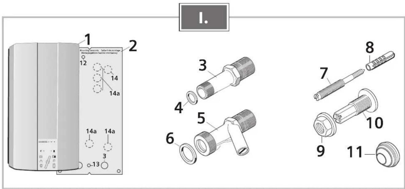
1. List of items supplied
1 Continuous-flow heater
2 Installation template
3 Connection piece for hot water
4 Washer, red ∅ 15 mm
5 Connection piece for cold water
6 Washer, ∅ 24 mm
7 Mounting bolt
8 Wall plug
9 Securing nut
10 Threaded bushing
11 Cable grommet
II. Wall mounting
There are two ways in which the continuous-flow heater can be mounted on the wall:
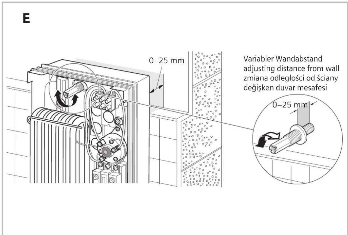
- Using the mounting bolt. Unevenness in the wall up to a depth of 25mm can be compensated for.
- Making use of the holes that were drilled for the old heater: Use the mounting template to establish whether the existing holes line up properly.
The following describes the installation procedure using the mounting bolt.
Marking the point for mounting the heater and selecting the opening for the connecting cable (Fig. A)
Important! Make sure that the connecting cable is isolated from the mains electricity supply!
Place hole 3 in the mounting template over the cold-water inlet.
Select the most suitable hole through which the connecting cable is be fed. The connecting cable must pass through one of the six holes marked 14... Terminal BZ45Z20M can be used if the cable is fed into the water heater through one of the bottom holes marked 14a.
■ Mark the point 12 at which the mounting bolt is to be inserted.
Fitting the mounting bolt and attaching the pipe connecting pieces (Fig. B)
Open up the heater (Fig. C)
Punching out the holes at the rear of the heater for the mounting bolt and the connecting cable
Important: When mounting the appliance, only the holes actually required should be punched out. Any other holes that are not going to be used must be sealed watertight.
Inserting the connecting cable (Fig. D)
- Push the grommet 11 over the end of the connecting cable.
Note: Do not use the grommet for a cable with a cross-section of 16 mm ^4 . The appliance must then be installed flush with the wall.
Attention: Without a grommet, the DH18100/21100/24100M is splashproof only (IP 24).
- Place the heater over the connecting cable.
Press the grommet into the hole in the rear wall of the heater through which the cable should be fed. Ensure that the edges of the grommet are flush with the hole all the way round.
■ Fit the heater onto the threaded bushing 8 and secure it in place with the nut 9.
Compensating for unevenness in the wall (Fig. E)

Water connection
■ Using the locking screw 15, the water connection can be aligned by ± 10 mm vertically.
Adapt the bend in the "hot" pipe so that it lines up with the hot-water outlet. In doing so, make sure that the "cold" elbow connection is not bent.
Attention: Ensure that a distance of at least 6 mm is maintained to live parts of the heater.
- Connect the water outlet and inlet and tighten the securing nut on the mounting bolt.
Checking for leaks and flushing the heater:
■ Turn on the hot-water tap.
- Check that all pipe joints are properly sealed.

Electrical connection
As a matter of principle, the water connections must be completed first of all before the heater is connected to the electricity supply (400 V AC, 3-phase). The appliance should be wired up according to the circuit diagram on the inside of the cover.
To guarantee compliance to relevant safety regulations, an all-pole separator must be fitted during installation. The contact opening must be at least 3 mm.
Terminal BZ45Z20M (special accessories) can be used if the connecting cable is fed into the heater via one of the bottom holes 14a!
The wires must not interfere with the operation of release button A on the safety temperature limiter.
Installation note
The installation of non plug-in ready appliances must be undertaken by the respective utility operator or by a qualified specialist company, who can also assist you when you are requesting the approval of the utility company for installation of the appliance.

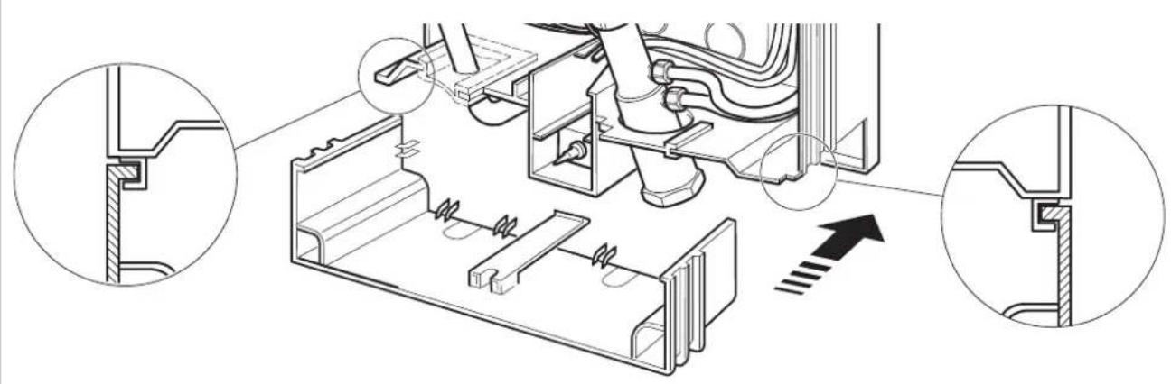
Mounting the cover onto the heater
- When you mount the cover onto the heater, ensure that the switch knob and the switch spindle are correctly aligned.

Startup
The device is compliant to IEC 61000-3-12.
- Switch on via the water heater fuses in the domestic wiring.
- Select Setting II on the appliance and check the water temperature.
At a low water-pipe pressure
■ Turn on additional cold-water taps and check whether the heater switches on. Remove the continuous-flow heater if the heater does not switch on (Fig. A).
Explain the appliance to the user and please give him the operating instructions.
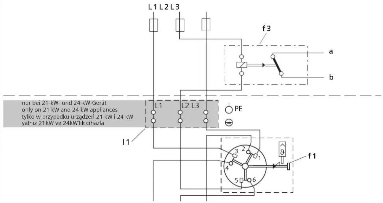
Priority switch for combination with electric storage heaters (Fig. B)
If the heater is going to be operated in this way, a priority switch must be connected into the line connecting the L2 phase to the appliance. It should be mounted on the meter or distribution panel.
a, b Control line for the electricity supply company connected to the coil input on the charging contactor
f1 Safety temperature limiter with mains terminals
f3 Priority switch (current relay)
I1 Mains terminal (only on 21 kW and 24 kW appliances)
Specifications
| DH18100M DH21100M DH24100M | |||
| Rated power [kW] | 18 21 24 | ||
| Rated voltage | 400V3~400V3~400V3~ | ||
| Heating capacity - economy setting e [kW] | - | ||
| 1st stage 6 7 8 | |||
| 2nd stage 12 14 16 | |||
| Heating capacity - intensive setting II [kW] | |||
| 1st stage 9 10.5 12 | |||
| 2nd stage 18 21 24 | |||
| Switch-on point [l/min] | |||
| 1st stage 4.0 4.5 5.0 | |||
| 2nd stage 5.0 5.8 6.6 | |||
| Mixed water [l/min] at rated power | |||
| approx. 38 °C 9.8 11.5 13.1 | |||
| approx. 50 °C (supply temperature 12 °C) | 6.7 7.8 9.0 | ||
| Minimum flow pressure of appliance* [MPa (bar)] | |||
| with flow limiter 0.6 (6) 0.8 (8) 0.9 (9) | |||
| without flow limiter 0.4 (4) 0.5 (5) 0.6 (6) | |||
| Energy efficiency class | B | B | B |
| Load profile | S | S | S |
| Annual energy consumption [kWh] | 495 497 501 | ||
| Daily energy consumption [kWh] | 2.301 | 2.313 | 2.337 |
| Sound power level [dB] | 15 15 15 | ||
| Hot water heating energy efficiency [%] | 37.2 37.1 36.8 | ||
* The pressure loss on the mixer must also be added.

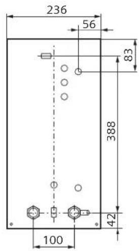
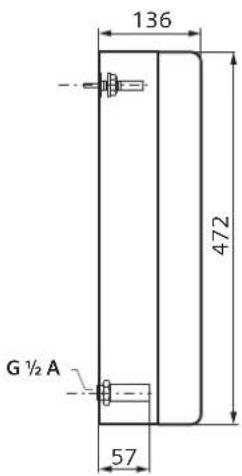
Dimensions
Special accessories
BZ45U20 Pipe set: for use of the continuous-flow heater as an under sink appliance
Intermediate terminal block BZ45Z20M: Required when the mains connecting cable is fed in through the bottom access hole 14a.
■ Priority switch (load shedding relay) BZ45L21: for operation with a priority circuit
■ Mounting kit BZ45K24M: for surface mount installation
Truncated connecting piece sealed at rear for water connection from below (e.g. cold water connection via fitting mounted below heater):
Elbow joint, "cold" (right)
Order no. 056169
Elbow joint, "hot", (left)
Order no. 255568
Operating instructions
Please read and observe the detailed safety instructions at the start of these instructions!
- Important: The appliance may never be exposed to frost!

Risk of electric shock!
Switch off the mains voltage supply immediately if a fault occurs.
- Immediately shut off the cold water supply to the appliance should it leak.
Getting to know your appliance
The continuous-flow heater heats the water as it flows through the appliance. The appliance only consumes power during this period.
This appliance can supply hot water to taps in several different locations. It should be installed close to the tap that is used the most frequently. This will enable you to reduce energy consumption.
Operating the appliance
The continuous-flow heater has two power settings:
e Economy setting – two thirds power
II Intensive setting – full power

The e setting is ideal for:

Wash basin

Shower

Bidet
II setting should be used where a higher temperature or a larger volume of water is required, e. g.

Dishwashing

Cleaning

Bath tub
If you are using a thermostat-controlled mixer tap, set the heater to II.
- Set the heater to either e or II, as required.
- Turn on the hot-water tap.
The continuous-flow heater switches on automatically and heats the water as it flows through the appliance.
The heater switches off again when you turn off the tap.
Increasing the water temperature
When the tap is turned on fully, it is possible that the heater capacity is not sufficient to heat the water to the required temperature.
Slightly close the hot-water tap. The water flows through the appliance more slowly and reaches a higher temperature as a result.
Decreasing the water temperature
Mix with cold water.
Note about operation
When a hot-water tap is turned on by only a small amount, the continuous-flow heater operates at half power regardless of which setting (e, II) has been selected.
When a hot-water tap is turned on fully, the appliance operates at the maximum level of power that corresponds to whichever setting has been selected.
Saving energy
- Please use economy setting "e" as often as possible.
To minimise energy consumption when turning off the hot water:
- Turn off the hot-water tap slowly in order to use the residual heat of the continuous-flow heater.
- This also prevents the water temperature from briefly increasing above the preselected temperature if the hot-water tap is turned on again within the next few minutes.
To obtain particularly uniform hot-water temperatures, it is recommended to use thermostat-controlled mixer taps.
The thermostat-controlled mixer tap must be suitable for hydraulically controlled continuous-flow heater.
Winter operation
Note: It is possible in winter that the supply temperature of the water is reduced and the required outlet temperature is no longer achieved.
In order to compensate for this temperature reduction, please reduce the water quantity on the tap until the required water temperature is achieved.
Cleaning
■ Simply wipe the appliance with a damp cloth.
Do not use acidic or abrasive cleaning materials.
Notes: It is normally not necessary to descale the appliance. However, extremely hard water and the frequent flows of very hot water can cause the appliance to scale up. In this case please contact our after-sales service.
A fault, what to do?

Attention!
Repairs must only be carried out by an authorised technician. Improper repairs can lead to risk of serious injury to the user.
If your appliance does not operate as required, it is often due to a very minor problem. Please check whether you can remedy the fault yourself by using the following guidelines. You will save yourself the costs of an unnecessary visit by customer service personnel.
The water does not heat up or not enough water flows out of the tap:
- Check the fuse in the fusebox.
- Drop in pressure in the water mains. If the pressure is too low, the appliance will not switch on.
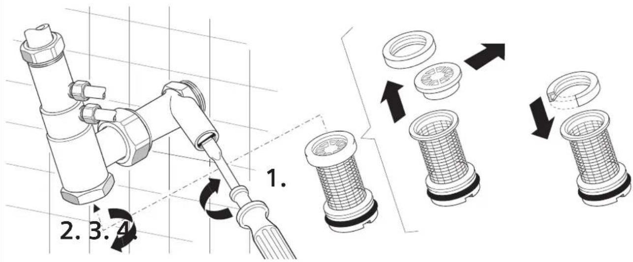
The strainer on the tap or shower head is blocked. Unscrew the strainer and either clean or descale it.
The corner valve is clogged. Turn on the hot-water tap fully and open and close the corner valve several times. Then clean the filter in the water tap.
The heater needs descaling. Arrange for a service engineer to visit.
The continuous-flow heater switches off during the drawing-off of water, resulting in a reduction in the watertemperature:
The washer inside the hot-water tap must be a non-swelling type.
If you cannot resolve the problem yourself, switch off the heater via the fuse in the domestic wiring. Arrange for a service engineer to visit.
After-sales service
If you call the after-sales service for assistance, please specify the E no. and FD no. of your appliance.
These numbers can be found on the underside of the continuous-flow heater.
Disposal
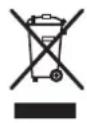
This appliance is labelled in accordance with European Directive 2012/19/EU concerning used electrical and electronic appliances (waste electrical and electronic equipment – WEEE).
The guideline determines the framework for the return and recycling of used appliances as applicable throughout the EU.
Please ask your specialist retailer about current disposal facilities.
Guarantee
The guarantee conditions for this appliance are as defined by our representative in the country in which it is sold.
Details regarding these conditions can be obtained from the dealer from whom the appliance was purchased. The bill of sale or receipt must be produced when making any claim under the terms of this guarantee.
Subject to change without notice.

natural_image
Illustration of an open book with a curved arrow pointing upward, no text or symbols present
natural_image
Line drawing of a mechanical device with arrows indicating motion, showing a switch and screwdriver (no text or symbols)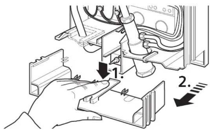

15
„warm“
"hot"
„ciepły“
"sıcak"
„kalt“
"cold"
„zimnej“
"soğuk"
+10
90–120 mm
18 kW 21 kW/24 kW

L1 L2 L3
A14aA 14a
natural_image
Technical line drawing of a mechanical assembly with cross-sectional views and dimension arrows (no text or symbols)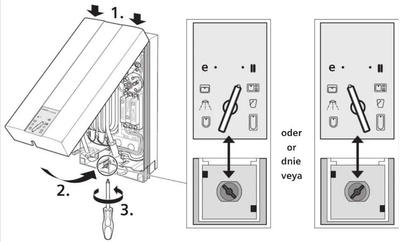
A
B
European Trade Center Building, 5th floor 1784 Sofia
Tel.: 0700 208 18
Fax: 02 878 79 72
mailto:informacia.servis-bg@bshg.com
www.siemens-home.bg
CH Schweiz, Suisse, Svizzera, Switzer
BSH Hausgeräte AG
Central Branch Service
17 km E.O. Athinon-Lamias &
Potamou 20
14564 Kifisia
Unit 1 & 2, 3rd Floor
North Block, Skyway House
3 Sham Mong Road
Tai Kok Tsui, Kowloon
Hong Kong
Tel.: 2565 6151
Fax: 2565 6681
mailto:siemens.hk.service@bshg.com
www.siemens-home.com.hk
HR Hrvatska, Croatia
BSH kućni uređaji d.o.o.
Kneza Branimira 22
10000 Zagreb
Tel:. 01 552 09 99
Fax: 01 640 36 03
mailto:informacije.servis-hr@bshg.com
www.siemens-home.com/hr
LU Luxembourg
www.siemens-home.com/lu
ME Crna Gora, Montenegro
Elektronika komerc
UI. Slobode 17
84000 Bijelo Polje
Tel./Fax: 050 432 575
Mobil: 069 324 812
mailto:ekobosch.servis@t-com.me
MK Macedonia, Makedonija
GORENEC
Jane Sandanski 69 lok. 3
1000 Skopje
Tel.: 022 454 600
Mobil:070 697 463
mailto:gorenec@yahoo.com
PH Philippines
Häfele Philippines, Incorporated
Levi Mariano Avenue, Brgy. Ususan,
Taguig City 1632
Metro Manila
Tel.: 0842 3353
Fax: 0571 3662
mailto:siemens-home@hafele.com.ph
PL Polska, Poland
2034/1-5 Ital Thai Building,
1st Floor, New Petchburi Road
Bangkapi, Huaykwang,
Bangkok, 10310
Tel.: 02 769 7970
Fax: 02 769 7971
Service Call Center 02 351 8995
Spareparts 02 769 7975
www.siemens-home.com/th
TR Türkiye, Turkey
BSH Ev Aletleri Sanayi
ve Ticaret A. S.
Fatih Sultan Mehmet Mahallesi
Balkan Caddesi No: 51
34771 Ümraniye, Istanbul
Tel.: 0 216 444 6688*
Fax: 0 216 528 9188
mailto:careline.turkey@bshg.com
www.siemens-home.com/tr
www.siemens-homeappliances.com
9001217905


- Sicherheitshinweise
- Eine Störung, was tun?
- Installation instructions
- Installation
- List of items supplied
- Wall mounting
- Important! Make sure that the connecting cable is isolated from the mains electricity supply!
- Water connection
- Electrical connection
- Installation note
- Mounting the cover onto the heater
- Startup
- At a low water-pipe pressure
- Priority switch for combination with electric storage heaters (Fig. B)
- Dimensions
- Special accessories
- Operating instructions
- Getting to know your appliance
- Operating the appliance
- Increasing the water temperature
- Decreasing the water temperature
- Note about operation
- Saving energy
- Winter operation
- Cleaning
- A fault, what to do?
- Attention!
- The water does not heat up or not enough water flows out of the tap:
- The continuous-flow heater switches off during the drawing-off of water, resulting in a reduction in the watertemperature:
- After-sales service
- Disposal
- Guarantee
- 15
- CH Schweiz, Suisse, Svizzera, Switzer
- HR Hrvatska, Croatia
- LU Luxembourg
- ME Crna Gora, Montenegro
- MK Macedonia, Makedonija
- PH Philippines
- PL Polska, Poland
- TR Türkiye, Turkey
Brand : SIEMENS
Model : DH24100M
Category : Instant water heater and boiler