
FUMO50025 - Wi-Fi repeater ABUS - Free user manual and instructions
Find the device manual for free FUMO50025 ABUS in PDF.

| Product Type | Wi-Fi Repeater |
| Brand | ABUS |
| Model | FUMO50025 |
| Dimensions (approx) | 100 x 60 x 30 mm |
| Weight (approx) | 100 g |
| Power Supply | 100-240 V AC, 50/60 Hz, direct plug-in |
| Power Consumption | < 10 W |
| Wi-Fi Standards | IEEE 802.11 b/g/n/ac |
| Frequency Bands | 2.4 GHz & 5 GHz |
| Maximum Data Rate | Up to 1200 Mbps (2.4 GHz: 300 Mbps, 5 GHz: 867 Mbps) |
| Functions | Range extension, WPS push-button, WPA2 security, LED indicators |
| Antenna Type | Internal antennas |
| Interface | 1x Gigabit Ethernet port (for wired connection) |
| Operating Temperature | 0°C to 40°C |
| Operating Humidity | < 90% (non-condensing) |
| Maintenance | Clean with a soft, dry cloth; do not use liquids |
| Safety | Use in dry indoor environment only; do not cover; ensure adequate ventilation |
| Spare Parts & Repairability | Not user-serviceable; for repair contact ABUS support |
| Package Contents | Wi-Fi Repeater, Quick Start Guide |
Frequently Asked Questions - FUMO50025 ABUS
User questions about FUMO50025 ABUS
0 question about this device. Answer the ones you know or ask your own.
Ask a new question about this device
Download the instructions for your Wi-Fi repeater in PDF format for free! Find your manual FUMO50025 - ABUS and take your electronic device back in hand. On this page are published all the documents necessary for the use of your device. FUMO50025 by ABUS.
USER MANUAL FUMO50025 ABUS
natural_image
Line drawing of a hand inserting a component into a device panel (no text or symbols)natural_image
Line drawing of a hand inserting a device into a washing machine (no text or symbols)natural_image
Front view of a mobile phone with keypad and display screen (no text or symbols)VARIANTE 1
natural_image
Diagram of an electronic device showing internal circuitry and a labeled panel (no readable text or symbols)Wählen Sie „Start“.
4

7

natural_image
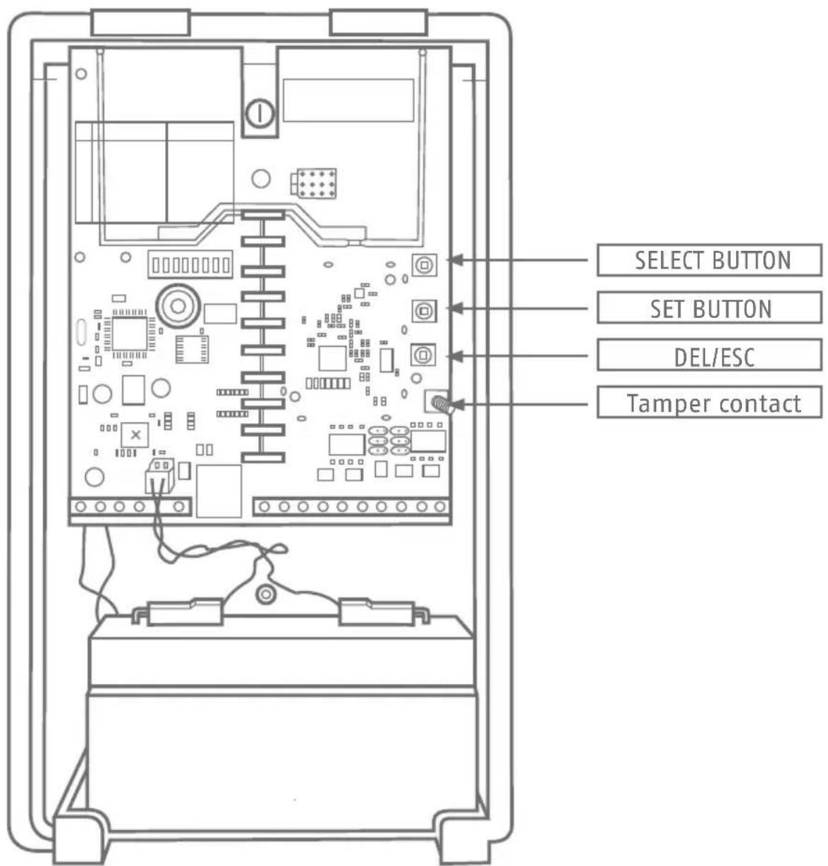
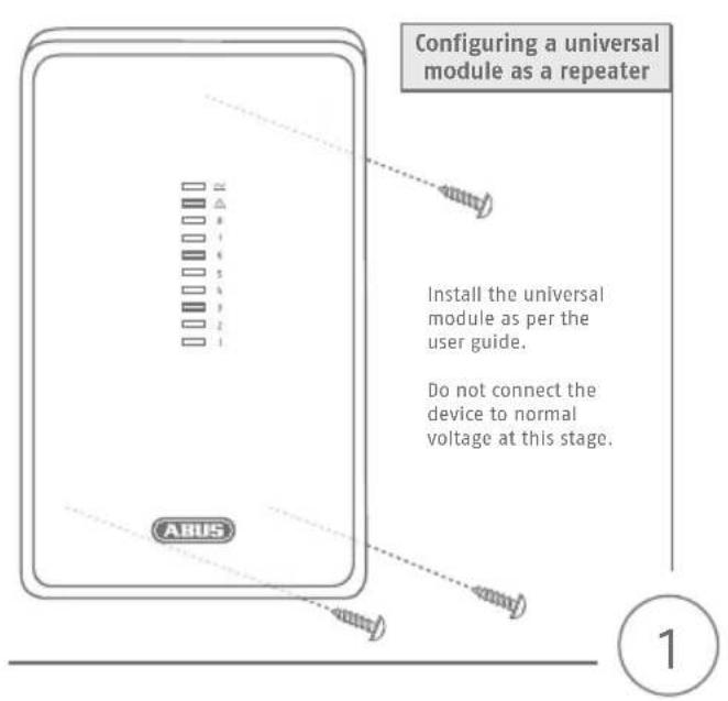
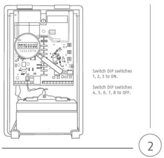
Diagram of an electronic device showing internal circuit board and labeled components (no readable text or symbols)Configuring a universal module as a repeater
abus.com


7
8
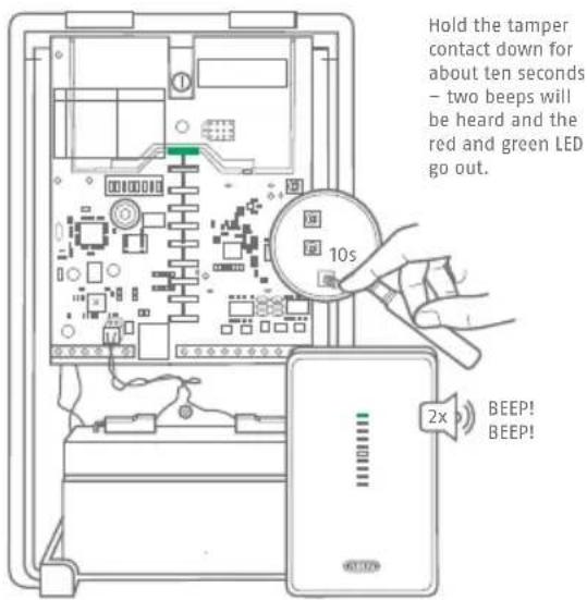
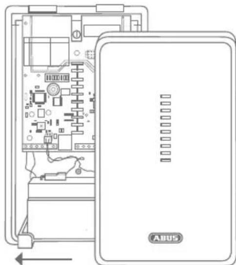
Hold the tamper contact down for about ten seconds – two beeps will be heard and the red and green LED go out.
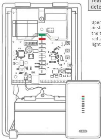
Teaching-in the wireless detector on the repeater
Open the housing cover or stop holding down the tamper contact. The red and green LEDs will light up.
9

Press the 'SELECT' button until the first LED from below lights up

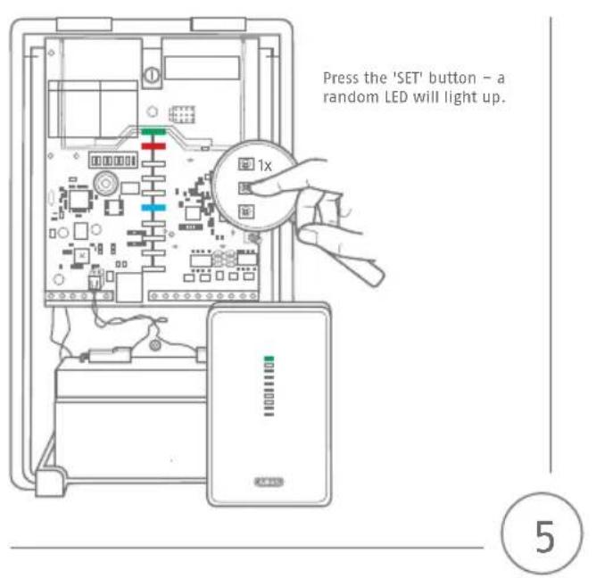
Press the 'SET' button. If a wireless detector has yet to be taught-in, none of the LEDs will light up.
If wireless detectors have already been taught-in, this will be indicated by the flashing of the LED corresponding to the relevant channel (1-8).
2
3
natural_image
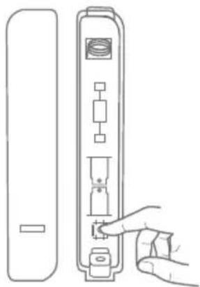
Line drawing of a hand inserting a component into a device panel (no text or symbols)Trigger the tamper contact of the detector or send a signal from the detector.
Once the signal has been received, the universal module will assign a new channel to the detector in question.
The LED corresponding to that channel will start to flash. Once the detector has been taught-in successfully, the universal module will beep twice.
Repeat step 2.4 to teach-in additional detectors.

natural_image
Line drawing of a hand inserting a device into a machine (no text or symbols)Please note that the detectors, which you have learned in the WAM, have also to be taught in the Secvest.
4
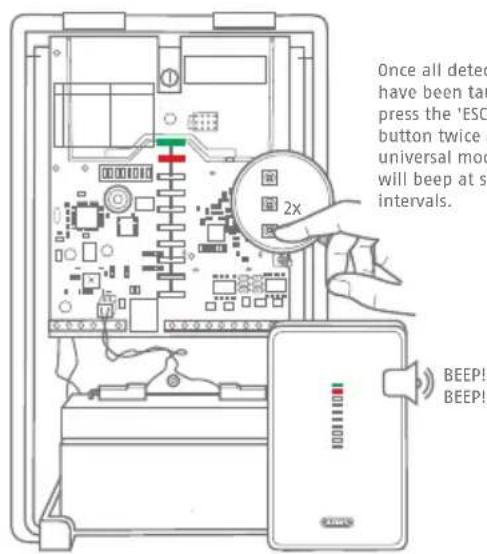
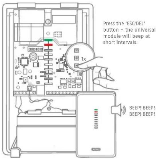
Once all detectors have been taught-in, press the 'ESC/DEL' button twice and the universal module will beep at short intervals.
6
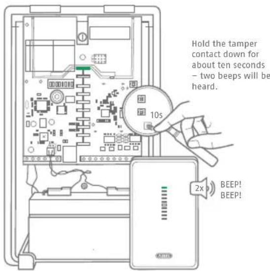
Hold the tamper contact down for about ten seconds – two beeps will be heard.
5
7
Teaching-in the universal module on the SECVEST alarm panel

natural_image
Front view of a mobile phone control panel with keypad and display (no text or symbols)OPTION 1
Teaching-in on the SECVEST panel:
Select a storage location with available space and confirm your choice by pressing 'Select'.
Trigger the tamper contact of the universal module – the alarm panel will audibly confirm receipt of the message.
natural_image
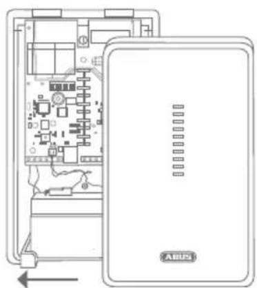
Diagram of an electronic device showing internal circuitry and a labeled panel (no text or symbols beyond label)Close the universal module housing and exit installer mode.
1
2
OPTION 2
Teaching-in via the SECVEST web interface (FW Version 2.00.00 or higher)
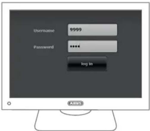
Access the SECVEST alarm panel web interface and log in using the installer login details.

Select -> Components -> Universal Module
2

find a storage location with available space and click on it to select it.
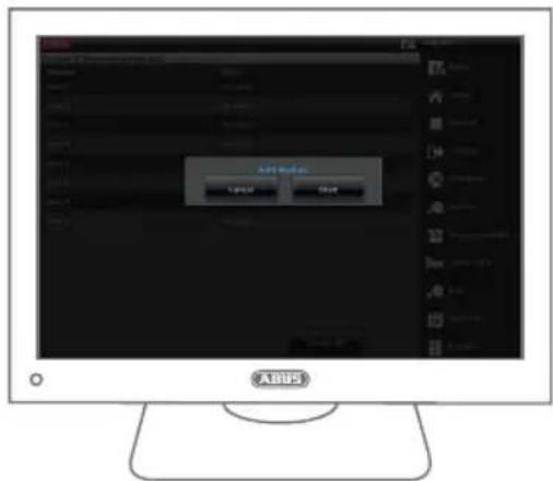
Select 'Start'.
4
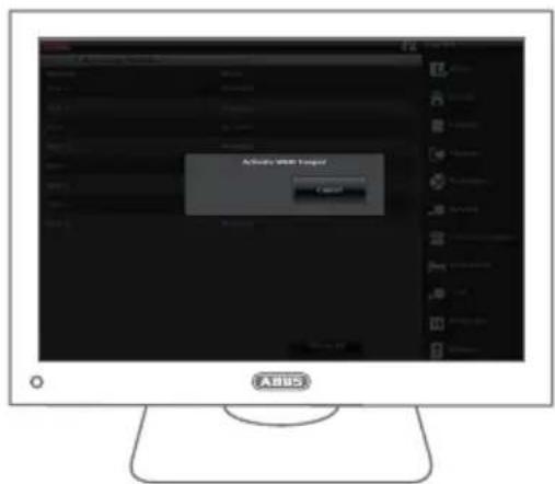
Trigger the tamper contact of the universal module.
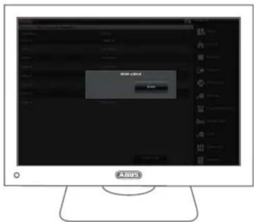
Once the teaching In has been completed successfully, the message 'Universal Module Added' will appear. Confirm by pressing 'Finish'.
6
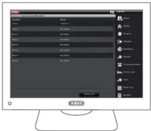
The universal module that has been taught in successfully will appear as 'Universal Module 01'
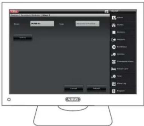
Manage the universal module type by clicking on the universal module that you just added. The universal module name can also be changed in this way.
8

7
natural_image
Diagram of an electronic device showing internal circuit board and labeled components (no readable text or symbols)Close the universal module housing.Select 'Apply'.
10
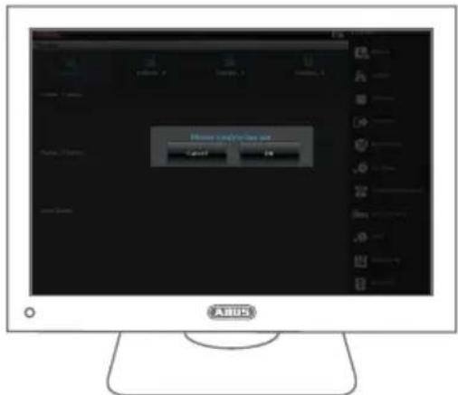
Select 'Log out' to exit installer mode.
Notes:
The universal module is not compatible with components from the Secvest portfolio that are capable of rolling code.
This concerns:
- Secvest Wireless Remote Control
- Secvest Wireless Control Device
- Secvest Wireless Key Switch
- Secvest Key
- Secvest Wireless Additional Door Lock
11
abus.com

Security Tech Germany
Brand : ABUS
Model : FUMO50025
Category : Wi-Fi repeater