T1600 - Router Juniper - Free user manual and instructions
Find the device manual for free T1600 Juniper in PDF.


| Product Type | Core Router |
| Model | T1600 |
| Dimensions (H x W x D) | Approximately 71.12 x 44.45 x 86.36 cm (28 x 17.5 x 34 in) |
| Weight (fully loaded) | Approximately 136 kg (300 lbs) |
| Switching Capacity | Up to 800 Gbps full-duplex (1600 Gbps half-duplex) |
| Forwarding Rate | Up to 1600 Mpps |
| Supported FPC Slots | 8 |
| Supported Interface Types | Gigabit Ethernet, 10-Gigabit Ethernet, 40-Gigabit Ethernet, 100-Gigabit Ethernet, SONET/SDH, ATM, Channelized, Services PICs |
| Power Supply Options | 3-Input 240-A DC, 4-Input 240-A DC, 6-Input DC, 3-Phase Delta AC, 3-Phase Wye AC |
| Redundancy | Redundant power supplies, fan trays, host subsystems, switch fabric, and control boards |
| Cooling | Front-to-back airflow with standard or quiet fan trays; field-replaceable |
| Operating Temperature | 0°C to 40°C (32°F to 104°F) |
| Relative Humidity | 5% to 90% noncondensing |
| Safety Compliance | NEBS, EMC Class A, UL, CE, VCCI, etc. |
| Maintenance | Field-replaceable units (FRUs) including power supplies, fan trays, FPCs, PICs, SIBs, control boards, and routing engines |
| Air Filter Maintenance | Front and rear air filters replaceable without tools; clean or replace as needed |
| ESD Protection | ESD points on front and rear of chassis |
| Management Ports | Console, auxiliary, and Ethernet ports on CIP; also via Routing Engine |
| Alarm Relay Contacts | Available on CIP for external alarm reporting |
| Supported Routing Engines | RE-600, RE-1600, RE-C1800, RE-2000 |
| Software | Junos OS |
| Documentation | T1600 Core Router Hardware Guide (636 pages, PDF) |
Frequently Asked Questions - T1600 Juniper
show chassis alarms or check the craft interface LCD and LEDs. The manual provides a comprehensive list of alarm messages and troubleshooting steps.User questions about T1600 Juniper
0 question about this device. Answer the ones you know or ask your own.
Ask a new question about this device
Download the instructions for your Router in PDF format for free! Find your manual T1600 - Juniper and take your electronic device back in hand. On this page are published all the documents necessary for the use of your device. T1600 by Juniper.
USER MANUAL T1600 Juniper
T1600 Core Router Hardware Guide
Published: 2014-12-19
Juniper Networks, Inc.
1194 North Mathilda Avenue
Sunnyvale, California 94089
USA
408-745-2000
www.juniper.net
Copyright © 2014, Juniper Networks, Inc. All rights reserved.
Juniper Networks, Junos, Steel-Belted Radius, NetScreen, and ScreenOS are registered trademarks of Juniper Networks, Inc. in the United States and other countries. The Juniper Networks Logo, the Junos logo, and JunosE are trademarks of Juniper Networks, Inc. All other trademarks, service marks, registered trademarks, or registered service marks are the property of their respective owners.
Juniper Networks assumes no responsibility for any inaccuracies in this document. Juniper Networks reserves the right to change, modify, transfer, or otherwise revise this publication without notice.
T1600 Core Router Hardware Guide
Copyright © 2014, Juniper Networks, Inc.
All rights reserved.
The information in this document is current as of the date on the title page.
YEAR 2000 NOTICE
Juniper Networks hardware and software products are Year 2000 compliant. Junos OS has no known time-related limitations through the year 2038. However, the NTP application is known to have some difficulty in the year 2036.
END USER LICENSE AGREEMENT
The Juniper Networks product that is the subject of this technical documentation consists of (or is intended for use with) Juniper Networks software. Use of such software is subject to the terms and conditions of the End User License Agreement ("EULA") posted at http://www.juniper.net/support/eula.html. By downloading, installing or using such software, you agree to the terms and conditions of that EULA.
Table of Contents
About the Documentation
Documentation and Release Notes
Supported Platforms
Documentation Conventions
Documentation Feedback
Requesting Technical Support
Self-Help Online Tools and Resources . . . . . . . . . . . . . . . . . . . . . . . . . . .
Opening a Case with JTAC . . . . . . . . . . . . . . . . . . . . . . . . . . . . .
Part 1 Overview
Chapter 1 System Overview and Architecture .....
T1600 Router Description ....
T1600 Component Redundancy
System Architecture Description for T Series Routers . . . . . . . . . . . . . . . . . . . . .
Routing Engine Functions for T Series Routers . . . . . . . . . . . . . . . . . . . . . . . . . .
Packet Forwarding Engine Architecture for T Series Routers . . . . . . . . . . . . . . . .
Packet Forwarding Engine Components
Data Flow
Chapter 2 T1600 Router Release Notes
Outstanding Issues with the T1600 Router . . . . . . . . . . . . . . . . . . . . . . . . . .
Errata with the T1600 Router Documentation . . . . . . . . . . . . . . . . . . . . . . .
Chapter 3 Chassis Components and Descriptions .....
T1600 Hardware Component Overview
T1600 Chassis Description
T1600 Midplane Description
T1600 Front Cable Management System Description . . . . . . . . . . . . . . . . . . . .
T1600 Rear Cable Management System Description . . . . . . . . . . . . . . . . . . . .
T1600 Connector Interface Panel (CIP) Description . . . . . . . . . . . . . . . . . . . . .
T1600 Connector Interface Panel (CIP) Components 25
Management Ports
T1600 Alarm Relay Contacts ....
T1600 Connector Interface Panel (CIP) LEDs
T1600 SONET Clock Generators Description . . . . . . . . . . . . . . . . . . . . . . . . . . .
T1600 SCG LEDs
T1600 Craft Interface Description
T1600 Craft Interface LCD and Navigation Buttons . . . . . . . . . . . . . . . . . . . . .
T1600 Craft Interface Alarm LEDs and ACO/LT Button . . . . . . . . . . . . . . . . .
T1600 Craft Interface Host Subsystem LEDs . . . . . . . . . . . . . . . . . . . . . . . .
T1600 Craft Interface SIB LEDs
T1600 Craft Interface FPC LEDs
Chapter 4 Cooling System Components and Descriptions ..... 37
T1600 Cooling System Description
Airflow 37
Fan Trays
Air Filters 40
Power Supply Cooling System
Chapter 5 Host Subsystem Components and Descriptions ..... 4
T1600 Host Subsystem Description
T1600 Routing Engine Description
T1600 RE-600 Description
T1600 RE-600 LEDs
T1600 RE-1600 Description
T1600 RE-1600 LEDs
T1600 RE-C1800 Description . . . . . . . . . . . . . . . . . . . . . . . . . . . . . . . . .
RE-C1800 Components .....
RE-C1800 Boot Order
T1600 RE-C1800 LEDs
T1600 RE-2000 Description
T1600 RE-2000 LEDs
Routing Engine Specifications . . . . . . . . . . . . . . . . . . . . . . . . . . . . . . . . . . . . . . . . . .
Supported Routing Engines by Router . . . . . . . . . . . . . . . . . . . . . . . . . . . . .
M7i Supported Routing Engines
M10i Supported Routing Engines . . . . . . . . . . . . . . . . . . . . . . . . . . . .
M40e Supported Routing Engines
M120 Supported Routing Engines
M320 Supported Routing Engines . . . . . . . . . . . . . . . . . . . . . . . . . . . .
MX104 Supported Routing Engines
MX240 Supported Routing Engines
MX480 Supported Routing Engines . . . . . . . . . . . . . . . . . . . . . . . . . . .
MX960 Supported Routing Engines . . . . . . . . . . . . . . . . . . . . . . . . . . .
MX2010 Supported Routing Engines . . . . . . . . . . . . . . . . . . . . . . . . . . . . .
MX2020 Supported Routing Engines
PTX3000 Supported Routing Engines
PTX5000 Supported Routing Engines . . . . . . . . . . . . . . . . . . . . . . . . . . . .
T320 Supported Routing Engines
T640 Supported Routing Engines
T1600 Supported Routing Engines . . . . . . . . . . . . . . . . . . . . . . . . . . .
T4000 Supported Routing Engines
TX Matrix Supported Routing Engines . . . . . . . . . . . . . . . . . . . . . . . . . . . .
TX Matrix Plus Supported Routing Engines . . . . . . . . . . . . . . . . . . . . . . . .
TX Matrix Plus (with 3D SIBs) Supported Routing Engines ..... 66
T1600 Control Boards Description . . . . . . . . . . . . . . . . . . . . . . . . . . . .
T1600 T Series Control Boards (T-CBs) Description . . . . . . . . . . . . . . . . . . .
T1600 T-CB LEDs
T1600 Line-Card Chassis Control Board (LCC-CB) Description 69
T1600 LCC-CB LEDs
Chapter 6 Line Card Components and Descriptions
T1600 Flexible PIC Concentrator (FPC) Description
T1600 FPC Function
T1600 FPC Slots
T1600 FPC Components
T1600 FPC Terminology
Identifying the T1600 FPCs
T1600 FPCs Supported
T1600 PIC Description
T1600 PICs Supported
ATM2 IQ PICs
Channelized PICs
DS3 and E3 PICs
Fast Ethernet PICs
Gigabit Ethernet PICs
10-Gigabit Ethernet PICs
40-Gigabit Ethernet PICs
100-Gigabit Ethernet PICs
Services PICs
SONET/SDH PICs
T1600 End-of-Life PICs Supported
T1600 PIC Combination Limitations
T1600 PIC/FPC Compatibility
PIC/FPC Compatibility (Type 1 FPCs and Type 1 PICs)
PIC/FPC Compatibility (Type 2 FPCs and Type 2 PICs) ..... 10
PIC/FPC Compatibility (Type 3 FPCs and Type 3 PICs) . . . . . . . . . . . . . . .
PIC/FPC Compatibility (Type 4 FPCs and Type 4 PICs) ..... 10
Chapter 7 Power System Components and Descriptions ..... 105
T1600 Power System Description
T1600 Three-Input 240-A DC Power Supply Description ..... 10
T1600 Three-Input 240-A DC Power Supply
T1600 Three-Input 240-A DC Power Supply Inputs ..... 1
T1600 Three-Input 240-A DC Power Supply Load Sharing and Fault Tolerance
T1600 Three-Input 240-A DC Power Supply LEDs
T1600 Four-Input 240-A DC Power Supply Description ..... 10
Four-Input 240-A DC Power Supply
Four-Input 240-A DC Power Supply Inputs . . . . . . . . . . . . . . . . . . . . . . . . .
Four-Input 240-A DC Power Supply Load Sharing and Fault Tolerance . . . . 110
T1600 Four-Input 240-A DC Power Supply LEDs
T1600 Six-Input DC Power Supply Description
Power Supply Components
Inputs 112
Redundancy
T1600 Six-Input DC Power Supply LEDs
T1600 Three-Phase Delta and Wye AC Power Supply Description ..... 114
Three-Phase Delta AC Power Supply
Three-Phase Wye AC Power Supply
AC Power Supply Load Sharing and Fault Tolerance
T1600 Three-Phase Delta and Wye AC Power Supply LEDs . . . . . . . . . . . . . .
Chapter 8 Switch Fabric Components and Descriptions ..... 1
T1600 Switch Interface Board (SIB) Description . . . . . . . . . . . . . . . . . . . . . .
T1600-SIB Description
T1600-SIB LEDs....121
TXP-T1600 SIB Description
TXP-T1600 SIB LEDs
T1600 TXP-LCC-3D SIB Description . . . . . . . . . . . . . . . . . . . . . . . . . . . . .
T1600 TXP-LCC-3D SIB LEDs . . . . . . . . . . . . . . . . . . . . . . . . . . . .
Part 2 Site Planning, Preparation, and Specifications
Chapter 9 Preparation Overview ...... 129
T1600 Site Preparation Requirements Checklist . . . . . . . . . . . . . . . . . . . . . . . . .
T1600 Environmental Specifications
T1600 Physical Specifications
T1600 Chassis Grounding Cable and Lug Specifications 1
Rack Requirements for the T1600 Router . . . . . . . . . . . . . . . . . . . . . . . . . .
Clearance Requirements for Airflow and T1600 Hardware Maintenance ..... 135
Chapter 10 DC Power Specifications and Requirements ..... 1
T1600 DC Power System Electrical Specifications . . . . . . . . . . . . . . . . . . . . . .
T1600 Three-Input 240-A DC Power Supply Specifications . . . . . . . . . . . . . . . . . . . . 138
T1600 Four-Input 240-A DC Power Supply Specifications . . . . . . . . . . . . . . . . . . . . . . . . . . . . . . . . . . . . . . . . . . . . 139
T1600 Six-Input DC Power Supply Specifications ....
T1600 DC Power Requirements . . . . . . . . . . . . . . . . . . . . . . . . . . . . . .
T1600 DC Power Distribution ....
T1600 DC Power Cables and Lugs . . . . . . . . . . . . . . . . . . . . . . . . . . . .
DC Power Cables . . . . . . . . . . . . . . . . . . . . . . . . . . . . . . . . . . . . . . .
DC Power Lugs . . . . . . . . . . . . . . . . . . . . . . . . . . . . . . . . . . . . . .
Chapter 11 AC Power Specifications and Requirements ..... 14
T1600 AC Power System Specifications
T1600 Three-Phase Delta AC Power Supply Specifications 148
T1600 Three-Phase Wye AC Power Supply Specifications ..... 14
T1600 AC Power Requirements
T1600 AC Power Cord Specifications . . . . . . . . . . . . . . . . . . . . . . . . . . .
Chapter 12 Network Cable and Transceiver Specifications ..... 15
Supported Network Interface Standards by Transceiver for the ACX, M, MX, and T Series
Understanding Fiber-Optic Cable Signal Loss, Attenuation, and Dispersion . . . . 162
Signal Loss in Multimode and Single-Mode Fiber-Optic Cable . . . . . . . . . . 162
Attenuation and Dispersion in Fiber-Optic Cable . . . . . . . . . . . . . . . . . . . . . .
Calculating Power Budget and Power Margin for Fiber-Optic Cables ..... 163
Calculating Power Budget for Fiber-Optic Cable . . . . . . . . . . . . . . . . . . . . . .
Calculating Power Margin for Fiber-Optic Cable . . . . . . . . . . . . . . . . . . . . .
Chapter 13 Management Cable Specifications and Pinouts ..... 167
T1600 Routing Engine Interface Cable and Wire Specifications ..... 16:
T1600 DB-9 Connector Pinouts for the Routing Engine AUXILIARY and CONSOLE Ports....168
T1600 RJ-45 Connector Pinouts for the Routing Engine ETHERNET Port . . . . . 168
Part 3 Initial Installation and Configuration
Chapter 14 T1600 Router Installation Overview . . . . . . . . . . . . . . . . . . . . . . . . . . . . .
Overview of Installing the T1600 Router . . . . . . . . . . . . . . . . . . . . . . . . . .
Chapter 15 Unpacking the T1600 Router . . . . . . . . . . . . . . . . . . . . . . . . . . . . . . . . . .
Overview of Unpacking the T1600 Router . . . . . . . . . . . . . . . . . . . . . . . . . .
Tools and Parts Required to Unpack the T1600 Router . . . . . . . . . . . . . . . .
Unpacking the T1600 Router . . . . . . . . . . . . . . . . . . . . . . . . . . . . . .
Verifying the T1600 Router Parts Received . . . . . . . . . . . . . . . . . . . . . . . . . .
Chapter 16 Installing the T1600 Mounting Hardware . . . . . . . . . . . . . . . . . . . . . . . . . .
Installing the T1600 Mounting Hardware for a Four-Post Rack or Cabinet ..... 181
Installing Cage Nuts, If Needed . . . . . . . . . . . . . . . . . . . . . . . . . . . . . . . . . . . . .
Installing the Large Mounting Shelf . . . . . . . . . . . . . . . . . . . . . . . . . . .
Installing the Small Shelf . . . . . . . . . . . . . . . . . . . . . . . . . . . . . . . .
Installing the Spacer Bars . . . . . . . . . . . . . . . . . . . . . . . . . . . . . . . . .
Removing the Center-Mounting Brackets from the Chassis ..... 184
Installing the T1600 Mounting Hardware for an Open-Frame Rack ..... 185
Installing the Cage Nuts, If Needed . . . . . . . . . . . . . . . . . . . . . . . . . . . . .
Installing the Large Mounting Shelf . . . . . . . . . . . . . . . . . . . . . . . . . . . . .
Removing the Center-Mounting Brackets from the Chassis ..... 187
Removing the Spacer Bars . . . . . . . . . . . . . . . . . . . . . . . . . . . . . . . .
Chapter 17 Installing the T1600 Router into a Rack . . . . . . . . . . . . . . . . . . . . . . . . . . .
Overview of Installing the T1600 Router into the Rack . . . . . . . . . . . . . . . . . .
Chapter 18 Installing the T1600 Router into a Rack Using a Mechanical Lift . . . . . . . 193
Overview of Installing a T1600 Router Using a Mechanical Lift . . . . . . . . . . . . . . . . 19
Tools Required to Install the T1600 Router Using a Mechanical Lift ..... 194
Removing the T1600 Power Supplies . . . . . . . . . . . . . . . . . . . . . . . . . . . . .
Attaching the T1600 Installation Handle . . . . . . . . . . . . . . . . . . . . . . . . . . .
Mounting the T1600 Chassis Using a Mechanical Lift . . . . . . . . . . . . . . . . . . .
Removing the T1600 Installation Handle and Reinstalling the Power Supplies
Chapter 19 Installing the T1600 Router into a Rack Without a Mechanical Lift . . . . . 201
Overview of Installing a T1600 Router Without a Mechanical Lift ..... 20'
Tools and Parts Required to Install the T1600 Router Without a Mechanical Lift 202
Removing Components from the T1600 Chassis . . . . . . . . . . . . . . . . . . . . . .
Removing the T1600 DC Power Supplies . . . . . . . . . . . . . . . . . . . . . . . .
Removing the T1600 AC Power Supplies . . . . . . . . . . . . . . . . . . . . . . . .
Removing the T1600 SIBs . . . . . . . . . . . . . . . . . . . . . . . . . . .
Removing the T1600 Control Boards . . . . . . . . . . . . . . . . . . . . . . . . . .
Removing the T1600 SCGs . . . . . . . . . . . . . . . . . . . . . . . . . . .
Removing the T1600 Standard or Quiet Rear Fan Tray 20
Removing the T1600 Front Cable Management System . . . . . . . . . . . . . . . 209
Removing the T1600 Standard or Quiet Front Fan Trays ..... 21
Removing the T1600 FPCs . . . . . . . . . . . . . . . . . . . . . . . . . . .
Installing the T1600 Chassis in the Rack Manually . . . . . . . . . . . . . . . . . . . .
Reinstalling the T1600 Components in the Chassis . . . . . . . . . . . . . . . . . . . .
Reinstalling the T1600 Standard or Quiet Rear Fan Tray . . . . . . . . . . . . . . . . . .
Reinstalling the T1600 SCGs . . . . . . . . . . . . . . . . . . . . . . . . . . . . .
Reinstalling the T1600 Control Boards . . . . . . . . . . . . . . . . . . . . . . . . .
Reinstalling the T1600 SIBs . . . . . . . . . . . . . . . . . . . . . . . .
Reinstalling the T1600 Power Supplies . . . . . . . . . . . . . . . . . . . . . . . . . .
Reinstalling the T1600 DC Power Supplies . . . . . . . . . . . . . . . . . . . . . . . . . . . . . .
Reinstalling the T1600 AC Power Supplies . . . . . . . . . . . . . . . . . . . . .
Reinstalling the T1600 FPCs . . . . . . . . . . . . . . . . . . . . . . . .
Reinstalling T1600 Standard Front Fan Trays . . . . . . . . . . . . . . . . . . . . .
Reinstalling T1600 Quiet Fan Trays . . . . . . . . . . . . . . . . . . . . . . . . .
Reinstalling the T1600 Front Cable Management System 225
Chapter 20 Connecting the T1600 Router to Ground . . . . . . . . . . . . . . . . . . . . . . . . . . . .
Tools and Parts Required to Ground the T1600 Router . . . . . . . . . . . . . . . . . .
Connecting the T1600 Grounding Cable . . . . . . . . . . . . . . . . . . . . . . . . . . . . . . .
Chapter 21 Connecting the T1600 Router to External Devices . . . . . . . . . . . . . . . . . . . . . . . . . . . . . . . . . 231
Overview of Connecting the T1600 Router to External Devices 23
Tools and Parts Required to Connect the T1600 Router to External Devices . . . 232
Connecting the T1600 Router to a Management Console or Auxiliary Device . . 232
Connecting the T1600 Router to a Network for Out-of-Band Management . . . 234
Connecting the T1600 Router to an External Alarm-Reporting Device ..... 235
Connecting PIC Cables to the T1600 Router . . . . . . . . . . . . . . . . . . . . . . . . . . .
Chapter 22 Providing Power to the T1600 Router . . . . . . . . . . . . . . . . . . . . . . . . . . . .
Tools and Parts Required to Provide Power to the T1600 Router . . . . . . . . . . . 23
Connecting DC Power to the T1600 Router (Three-Input 240-A DC Power Supplies or Four-Input 240-A DC Power Supplies) ..... 24
Connecting DC Power to the T1600 Router (Six 60-A Inputs to Six-Input DC Power Supplies)
Connecting DC Power to the T1600 Router (Five 60-A Inputs to Six-Input DC Power Supplies)
Powering On the DC-Powered T1600 Router . . . . . . . . . . . . . . . . . . . . . . . .
Connecting AC Power to a T1600 Router with Three-Phase Delta AC Power Supplies
Connecting AC Power to a T1600 Router with Three-Phase Wye AC Power Supplies
Powering On the AC-Powered T1600 Router . . . . . . . . . . . . . . . . . . . . . . . . . .
Powering Off the T1600 Router . . . . . . . . . . . . . . . . . . . . . . . . . . . . . . . .
Chapter 23 Configuring the JUNOS Software . . . . . . . . . . . . . . . . . . . . . . . . . . . . . . . .
Initially Configuring the T1600 Router ..... Preparing to Configure the T1600 Router ..... Entering Configuration Mode ..... Configuring User Accounts and Passwords ..... Configuring System Attributes ..... Committing the Configuration ..... Configuring DC Power on a T1600 Router ..... Configuring DC Power on a T1600 Router (Five 60-A Cables on a Six-Input DC Power Supply) ....
Chapter 24 Upgrading to a T1600 Router from a T640 Router . . . . . . . . . . . . . . . . . . . . . . . . . . . . . . . . 26
Overview of Upgrading a T640 Router to a T1600 Router .... 2 Hardware Required for Upgrading from a T640 Router to a T1600 Router .... 270 T640 to T1600 Upgrade Kit .... 271 Verifying the Hardware Versions Before an Upgrade to a T1600 Router .... 271 Verifying the Hardware Version of the Control Board .... 2 Verifying the Hardware Version of the Rear Fan Tray .... 2 Verifying the Hardware Version of the Power Supplies .... 2
Tools Required to Upgrade a T640 Router to a T1600 Router ..... Upgrading to a Supported T1600 Rear Fan Tray ..... Removing the RHTREARTRAY-T Rear Fan Tray ..... Installing a Rear Fan Tray ....
Upgrading to Supported T1600 Power Supplies ...... Removing a Two-Input 160-A DC Power Supply ...... Installing a T1600 Power Supply ....
Upgrading to T1600 SIBs ...... Preparing to Upgrade the SIBs ...... Removing a Standard SIB or SIB Version B ...... Installing a T1600-SIB ...... Verifying the Installation of a T1600-SIB ...... Exiting Upgrade Mode ...... Verifying Operation ...... .....
Upgrading to a T1600 Craft Interface ...... Removing the T1600 Upper Front Fan Tray ...... Removing the T640 Craft Interface ...... Installing the T1600 Craft Interface ...... Reinstalling the T1600 Upper Front Fan Tray ...... ....
Attaching the T1600 Agency Label ...... Registering Your T1600 Upgrade ...... ......
Part 4 Installing and Replacing Components
Chapter 25 Overview of Installing and Replacing Components ..... 301
T1600 Field-Replaceable Units
Tools and Parts Required for Replacing T1600 Hardware Components ..... 302
Chapter 26 Replacing Chassis Components
Replacing the T1600 Front Air Filter ...... Removing the T1600 Front Air Filter ...... Installing the T1600 Front Air Filter ....
Replacing the T1600 Rear Air Filter ...... Removing a Rear T1600 Air Filter ...... Installing the T1600 Rear Air Filter ....
Replacing the T1600 Alarm Relay Wires ...... Removing the T1600 Alarm Relay Wires ...... Installing the T1600 Alarm Relay Wires ....
Replacing a T1600 Console or Auxiliary Cable ...... Removing a T1600 Console or Auxiliary Cable ...... Installing a T1600 Console or Auxiliary Cable ....
Replacing a T1600 Management Ethernet Cable ...... Removing a T1600 Management Ethernet Cable ...... Installing a T1600 Management Ethernet Cable ....
Replacing a T1600 CIP ...... Removing a T1600 CIP ...... Installing a T1600 CIP ....
Replacing the T1600 Craft Interface ...... Removing the T1600 Craft Interface ...... Installing the T1600 Craft Interface ....
Replacing a T1600 SCG ...... Removing a T1600 SCG ...... Installing the T1600 SCG ....
Chapter 27 Replacing Cooling System Components
Replacing the T1600 Standard Lower Front Fan Tray ...... Removing the T1600 Standard Lower Front Fan Tray ...... Installing the T1600 Standard Lower Front Fan Tray ...... 3
Replacing the T1600 Standard Upper Front Fan Tray ...... Removing the T1600 Standard Upper Front Fan Tray ...... Installing the T1600 Standard Upper Front Fan Tray ...... 3
Replacing the T1600 Rear Fan Tray ...... Removing the T1600 Rear Fan Tray ...... Installing the T1600 Rear Fan Tray ....
Upgrading to the T1600 Quiet Fan Trays ..... Upgrading the Standard Lower Front Fan Tray to a Quiet Lower Front Fan Tray ....
Removing the Standard Upper Front Fan Tray ..... Removing the Craft Interface ..... Installing the Air Deflector and Craft Interface ..... Installing the Quiet Upper Front Fan Tray ....
Upgrading the Standard Rear Fan Tray to a Quiet Rear Fan Tray . . . . . . . . 33:
Replacing the T1600 Quiet Lower Front Fan Tray ...... Removing the T1600 Quiet Lower Front Fan Tray ...... Installing the T1600 Quiet Lower Front Fan Tray ....
Replacing the T1600 Quiet Upper Front Fan Tray . . . . . . . . . . . . . . . . . . . . .
Removing the Quiet Upper Front Fan Tray . . . . . . . . . . . . . . . . . . . . . . . .
Installing the Quiet Upper Front Fan Tray . . . . . . . . . . . . . . . . . . . . . . .
Replacing the T1600 Quiet Rear Fan Tray . . . . . . . . . . . . . . . . . . . . . . . . .
Removing the Quiet Rear Fan Tray . . . . . . . . . . . . . . . . . . . . . . . . . . . . .
Installing the Quiet Rear Fan Tray . . . . . . . . . . . . . . . . . . . . . . . . . . . .
Replacing the T1600 Lower Front Fan Tray (FANTRAY-T4000) 344
Removing the T1600 Lower Front Fan Tray (FANTRAY-T4000) ..... 344
Installing the T1600 Lower Front Fan Tray (FANTRAY-T4000) . . . . . . . . . 345
Replacing the T1600 Upper Front Fan Tray (FANTRAY-T4000) ..... 346
Removing the T1600 Upper Front Fan Tray (FANTRAY-T4000) ..... 346
Installing the T1600 Upper Front Fan Tray (FANTRAY-T4000) . . . . . . . . . 347
Chapter 28 Replacing Host Subsystem Components
Taking the T1600 Host Subsystem Offline . . . . . . . . . . . . . . . . . . . . . . . . . . . . .
Replacing a T1600 T-CB . . . . . . . . . . . . . . . . . . . . . . . . . . . . . . . .
Removing a T1600 T-CB . . . . . . . . . . . . . . . . . . . . . . . . . . . .
Installing a T1600 T-CB . . . . . . . . . . . . . . . . . . . . . . . . . . . . . . . . .
Replacing a T1600 LCC-CB
Removing a T1600 LCC-CB . . . . . . . . . . . . . . . . . . . . . . .
Installing a T1600 LCC-CB . . . . . . . . . . . . . . . . . . . . . . . . . . . . . . .
Replacing a T1600 Routing Engine . . . . . . . . . . . . . . . . . . . . . . . . . . . .
Removing a T1600 Routing Engine . . . . . . . . . . . . . . . . . . . . . . . . . . . .
Installing the T1600 Routing Engine . . . . . . . . . . . . . . . . . . . . . . . . . . .
Verifying the Installation of the T1600 Routing Engine . . . . . . . . . . . . . . . . . 360
Replacing a CompactFlash Card in a T1600 RE-C1800 Routing Engine ..... 361
Preparing to Replace a CompactFlash Card in a T1600 C1800 Routing Engine
Removing a CompactFlash Card in a T1600 C1800 Routing Engine ..... 363
Installing a CompactFlash Card in a T1600 C1800 Routing Engine . . . . . . 364
Copying Junos OS to the CompactFlash Card in a T1600 C1800 Routing Engine
Replacing a DIMM Module in a T1600 Routing Engine . . . . . . . . . . . . . . . . . .
Removing a T1600 DIMM Module . . . . . . . . . . . . . . . . . . . . . . . . . . .
Installing a T1600 DIMM Module . . . . . . . . . . . . . . . . . . . . . . . . . . .
Replacing a PC Card in a T1600 Routing Engine . . . . . . . . . . . . . . . . . . . . . .
Removing a T1600 PC Card . . . . . . . . . . . . . . . . . . . . . . . . . . .
Installing the T1600 PC Card . . . . . . . . . . . . . . . . . . . . . . . . . . . .
Replacing a Solid-State Disk in a T1600 RE-C1800 Routing Engine . . . . . . . . . 369
Preparing to Replace a Solid-State Disk in a T1600 RE-C1800 Routing Engine
Removing a Solid-State Disk in a T1600 RE-C1800 Routing Engine ..... 372
Installing a Solid-State Disk in a T1600 RE-C1800 Routing Engine . . . . . . . 373
Copying Junos OS to the Solid-State Disk in a T1600 RE-C1800 Routing Engine . . . . . . . . . . . . . . . . . . . . . . . . . . . . . . . . . . . . . . . . . . .
Chapter 29 Replacing Line Card Components .....
Replacing a T1600 FPC ...... Removing a T1600 FPC ...... Installing a T1600 FPC ....
Replacing a T1600 PIC ...... Removing a T1600 PIC ...... Installing a T1600 PIC ....
Replacing a T1600 PIC Cable ...... Removing a T1600 PIC Cable ...... Installing a T1600 PIC Cable ....
Chapter 30 Replacing Power System Components .....
Tools and Parts Required for Replacing T1600 DC Power System Components
Replacing a T1600 Three-Input 240-A DC Power Supply . . . . . . . . . . . . . . . . . . . . . . . . . . . . . . . 3
Removing a T1600 Three-Input 240-A DC Power Supply .... 394 Setting the Input Mode Switch on a T1600 Three-Input 240-A DC Power Supply ....
Installing a T1600 Three-Input 240-A DC Power Supply . . . . . . . . . . . . . . . . . . . . . 398
Replacing a Cable Restraint on the T1600 Three-Input 240-A DC Power Supply ...... Removing the Standard Cable Restraint from the T1600 Three-Input 240-A Power Supply ...... Installing the Optional Cable Restraint on the T1600 Three-Input 240-A DC Power Supply ...... .....
Connecting a Replacement T1600 Three-Input 240-A DC Power Supply . . 401 Powering On a Replacement T1600 Three-Input 240-A DC Power Supply . . . . . . . . . . . . . . . . . . . . . . . . . . . . . . . . . . . . .
Replacing a T1600 Four-Input 240-A DC Power Supply ..... Removing a T1600 Four-Input 240-A DC Power Supply ..... Installing a T1600 Four-Input 240-A Power Supply ..... ..... .... ....
Replacing a T1600 Six-Input DC Power Supply ...... Removing a T1600 Six-Input DC Power Supply ...... Installing a T1600 Six-Input DC Power Supply ....
Replacing a T1600 DC Power Supply Cable on a Six-Input DC Power Supply . . . 421
Removing a T1600 DC Power Supply Cable From a Six-Input DC Power Supply .....
Installing a T1600 DC Power Supply Cable on a Six-Input DC Power Supply ....
Replacing a T1600 Six-Input DC Power Supply Front Air Filter . . . . . . . . . . . . . . 42
Removing a T1600 Six-Input DC Power Supply Front Air Filter . . . . . . . . . 424
Installing a T1600 Six-Input DC Power Supply Front Air Filter . . . . . . . . . . 424
Replacing a T1600 Six-Input DC Power Supply Side Air Filter . . . . . . . . . . . . . . . . . . . . . . . . . . .
Removing a T1600 Six-Input DC Power Supply Side Air Filter . . . . . . . . . . 424
Installing a T1600 Six-Input DC Power Supply Side Air Filter . . . . . . . . . . . . . 425
Replacing a T1600 Three-Phase Delta AC Power Supply 4
Removing a T1600 Three-Phase Delta AC Power Supply . . . . . . . . . . . . . . . . 426
Installing a T1600 Three-Phase Delta AC Power Supply . . . . . . . . . . . . . . . . 430
Replacing a T1600 Three-Phase Delta AC Power Supply Cord 43
Removing a T1600 Three-Phase Delta AC Power Supply Cord . . . . . . . . . 433
Installing a T1600 Three-Phase Delta AC Power Supply Cord . . . . . . . . . . . 436
Replacing a T1600 Three-Phase Wye AC Power Supply . . . . . . . . . . . . . . . .
Removing a T1600 Three-Phase Wye AC Power Supply . . . . . . . . . . . . . . . . . 438
Installing a T1600 Three-Phase Wye AC Power Supply . . . . . . . . . . . . . . . . . 44
Replacing a T1600 Three-Phase Wye AC Power Supply Cord 44
Removing a T1600 Three-Phase Wye AC Power Supply Cord . . . . . . . . . . 444
Installing a T1600 Three-Phase Wye AC Power Supply Cord . . . . . . . . . . 446
Chapter 31 Replacing Switch Fabric Components
Replacing a T1600-SIB
Removing a T1600-SIB . . . . . . . . . . . . . . . . . . . . . . . . . . . . .
Installing a T1600-SIB
Verifying the Installation of a T1600-SIB . . . . . . . . . . . . . . . . . . . . . . . .
Replacing a TXP-T1600 SIB
Removing a TXP-T1600 SIB . . . . . . . . . . . . . . . . . . . . . . . . . . .
Installing a TXP-T1600 SIB
Verifying the Installation of a TXP-T1600 SIB . . . . . . . . . . . . . . . . . . . . . .
Replacing a T1600 TXP-LCC-3D SIB
Removing a T1600 TXP-LCC-3D SIB . . . . . . . . . . . . . . . . . . . . . . . . . . .
Installing a T4000 TXP-LCC-3D SIB . . . . . . . . . . . . . . . . . . . . . . . . . . . . . . .
Replacing a T1600 SFP
Removing a T1600 SFP
Installing a T1600 SFP . . . . . . . . . . . . . . . . . . . . . . . . . . . . .
Replacing a T1600 XFP . . . . . . . . . . . . . . . . . . . . . . . . . . . . . . .
Removing a T1600 XFP . . . . . . . . . . . . . . . . . . . . . . . . . . . .
Installing a T1600 XFP
Replacing a T1600 XENPAK Module . . . . . . . . . . . . . . . . . . . . . . . . . . . . .
Removing the T1600 XENPAK Module . . . . . . . . . . . . . . . . . . . . . . . .
Installing the T1600 XENPAK Module . . . . . . . . . . . . . . . . . . . . . . . . . .
Part 5 Maintaining the Chassis and Components
Chapter 32 Routine Maintenance Procedures
Routine Maintenance Procedures for the T1600 Router 4
Chapter 33 Maintaining Components
Tools and Parts Required to Maintain the T1600 Hardware Components ..... 475
Maintaining the T1600 Air Intake Vents . . . . . . . . . . . . . . . . . . . . . . . . . . . .
Maintaining the T1600 Air Filters . . . . . . . . . . . . . . . . . . . . . . . . . . . . .
Maintaining the T1600 Control Boards . . . . . . . . . . . . . . . . . . . . . . . . . . .
Maintaining the T1600 Fan Trays . . . . . . . . . . . . . . . . . . . . . . . . . . . . . . . .
Maintaining T1600 FPCs . . . . . . . . . . . . . . . . . . . . . . . . . . . . .
Holding T1600 FPCs ...... Preventing Damage to FPCs ...... Holding T1600 FPCs Vertically ...... Holding T1600 FPCs Horizontally ....
Storing T1600 FPCs
Maintaining the T1600 Host Subsystem ..... Maintaining the T1600 Routing Engines ..... Maintaining the T1600 Control Boards ....
Maintaining T1600 PICs and PIC Cables . . . . . . . . . . . . . . . . . . . . . . . . . .
Maintaining the T1600 Power Supplies . . . . . . . . . . . . . . . . . . . . . . . . . . . .
Maintaining the T1600 Routing Engines . . . . . . . . . . . . . . . . . . . . . . . . . . . . . . . .
Maintaining the T1600 SCGs . . . . . . . . . . . . . . . . . . . . . . . . . . . .
Maintaining the T1600 SIBs
Cleaning Fiber-Optic Array Components with the Dry Cloth Cleaning Tool . . . . 496
Part 6 Troubleshooting Hardware
Chapter 34 Troubleshooting Components
T1600 Troubleshooting Resources
T1600 LED Overview
Craft Interface LED Overview
Component LED Overview
T1600 Alarm Messages Overview
Troubleshooting the T1600 Cooling System . . . . . . . . . . . . . . . . . . . . . . . . . .
Troubleshooting the T1600 Craft Interface . . . . . . . . . . . . . . . . . . . . . . . .
Troubleshooting the T1600 Host Subsystems . . . . . . . . . . . . . . . . . . . . . . .
Troubleshooting the T1600 Control Boards . . . . . . . . . . . . . . . . . . . . . . . . . .
Troubleshooting the T1600 Cooling System . . . . . . . . . . . . . . . . . . . . . . . . .
Troubleshooting the T1600 FPCs
Troubleshooting the T1600 Power System . . . . . . . . . . . . . . . . . . . . . . . . . .
Troubleshooting the T1600 PICs . . . . . . . . . . . . . . . . . . . . . . . . . . . . .
Troubleshooting the T1600 SCGs . . . . . . . . . . . . . . . . . . . . . . . . . .
Troubleshooting the T1600 SIBs . . . . . . . . . . . . . . . . . . . . . . . . .
Testing a Fiber-Optic Array Switching Plane Port . . . . . . . . . . . . . . . . . . . . . . .
Testing a Fiber-Optic Array Switching Plane Cable . . . . . . . . . . . . . . . . . . . . . .
Part 7 Contacting Customer Support and Returning the Chassis or Components
Chapter 35 Contacting Customer Support
Contacting Customer Support . . . . . . . . . . . . . . . . . . . . . . . . . . . . . . . . . . . . . .
Chapter 36 Locating Component Serial Numbers .....
Locating T1600 Component Serial Numbers Using the CLI 5
T1600 Component Serial Number Label Locations . . . . . . . . . . . . . . . . . . . . . .
Control Board Serial Number Label
CIP Serial Number Label
Craft Interface Serial Number Label
FPC Serial Number Label
PIC Serial Number Label
Power Supply Serial Number Label . . . . . . . . . . . . . . . . . . . . . . . . . . . . .
Routing Engine Serial Number Label . . . . . . . . . . . . . . . . . . . . . . . . . . . . . . . . . . . . . . .
SCG Serial Number Label . . . . . . . . . . . . . . . . . . . . . . . . . . . . .
SIB Serial Number Label
Chapter 37 Packing and Returning Components .....
Tools and Parts Required to Remove Components from a T1600 Router ..... 541
Packing the T1600 Router for Shipment . . . . . . . . . . . . . . . . . . . . . . . . . .
Packing the T1600 Router Components for Shipment 5
Returning a Hardware Component to Juniper Networks, Inc. 543
Part 8 Safety and Compliance Information
Chapter 38 General Safety Guidelines and Warnings . . . . . . . . . . . . . . . . . . . . . . . . . .
Definition of Safety Warning Levels . . . . . . . . . . . . . . . . . . . . . . . . . . . . . . . .
General Safety Guidelines for Juniper Networks Devices . . . . . . . . . . . . . . . . . . . . . . . . . . . 5
General Safety Warnings for Juniper Networks Devices . . . . . . . . . . . . . . . . . .
Qualified Personnel Warning . . . . . . . . . . . . . . . . . . . . . . . . . . . . . . .
Restricted Access Area Warning
T1600 Preventing Electrostatic Discharge Damage . . . . . . . . . . . . . . . . . . . . .
Chapter 39 Fire Safety Requirements .... 557
Fire Safety Requirements for Juniper Networks Devices . . . . . . . . . . . . . . . . . . .
General Fire Safety Requirements . . . . . . . . . . . . . . . . . . . . . . . . . . . . .
Fire Suppression
Fire Suppression Equipment . . . . . . . . . . . . . . . . . . . . . . . . . . . . . . . .
Chapter 40 Installation Safety Guidelines and Warnings ..... 5
T1600 Chassis Lifting Guidelines . . . . . . . . . . . . . . . . . . . . . . . . . . . . . . .
Installation Safety Warnings for Juniper Networks Devices 55
Intra-Building Ports Warning . . . . . . . . . . . . . . . . . . . . . . . . . . . . . .
Installation Instructions Warning . . . . . . . . . . . . . . . . . . . . . . . . . . . . .
Rack-Mounting Requirements and Warnings .....
Ramp Warning
Chapter 41 Laser and LED Safety Guidelines and Warnings ..... 5
T1600 General Laser Safety Guidelines . . . . . . . . . . . . . . . . . . . . . . . . . . .
Laser Safety Warnings for Juniper Networks Devices . . . . . . . . . . . . . . . . . . . .
Class 1 Laser Product Warning . . . . . . . . . . . . . . . . . . . . . . . . . . .
Class 1 LED Product Warning . . . . . . . . . . . . . . . . . . . . . . . . . . . . . . .
Laser Beam Warning ....
Radiation from Open Port Apertures Warning . . . . . . . . . . . . . . . . . . . . . .
Chapter 42 Maintenance and Operational Safety Warnings . . . . . . . . . . . . . . . . . . . . . . . . . . . . . . . . . . . . . . . . . . . . . . 56
Maintenance and Operational Safety Warnings for Juniper Networks Devices . . 569 Battery Handling Warning ...... Jewelry Removal Warning ...... Lightning Activity Warning ...... Operating Temperature Warning ...... Product Disposal Warning ...... ....
Chapter 43 Electrical Guidelines and Warnings .....
T1600 General Electrical Safety Guidelines .... 576 General Electrical Safety Warnings for Juniper Networks Devices .... 576 Grounded Equipment Warning .... 576 Grounding Requirements and Warning .... 576 Midplane Energy Hazard Warning .... 576 Multiple Power Supplies Disconnection Warning .... 576 Power Disconnection Warning .... 576
T1600 DC Power Electrical Safety Guidelines .... 581 DC Power Electrical Safety Warnings for Juniper Networks Devices .... 581 DC Power Copper Conductors Warning .... 581 DC Power Disconnection Warning .... 581 DC Power Wiring Terminations Warning .... 581 Site Electrical Wiring Guidelines for Juniper Networks Devices .... 584 Distance Limitations for Signaling .... 584 Radio Frequency Interference .... 584 Electromagnetic Compatibility .... 584
Chapter 44 Agency Approvals and Compliance Statements ..... 587
T1600 Agency Approvals ...... Compliance Statements for EMC Requirements for Juniper Networks Devices (Canada) ...... T1600 Compliance Statements for EMC Requirements (European Community) ...... Compliance Statements for EMC Requirements for Juniper Networks Devices (Israel) ...... Compliance Statements for EMC Requirements for Juniper Networks Devices (Japan) ...... Compliance Statements for EMC Requirements for Juniper Networks Devices (United States) ...... Compliance Statements for Environmental Requirements for Juniper Networks Devices ...... T1600 Compliance Statements for NEBS ...... T1600 Compliance Statements for Acoustic Noise ....
Part 9 Index
Index 595
List of Figures
Part 1 Overview
Chapter 1 System Overview and Architecture .....
Figure 1: Front View of the T1600 Router . . . . . . . . . . . . . . . . . . . . . . . . . .
Figure 2: Rear View of the T1600 Router . . . . . . . . . . . . . . . . . . . . . . . . .
Figure 3: Router Architecture .....
Figure 4: Control Packet Handling for Routing and Forwarding Table Updates....7
Figure 5: Data Flow Through the Router . . . . . . . . . . . . . . . . . . . . . . . . . . . .
Chapter 3 Chassis Components and Descriptions .....
Figure 6: Front View of Router Chassis
Figure 7: Rear View of Router Chassis . . . . . . . . . . . . . . . . . . . . . . . . . . .
Figure 8: Midplane 22
Figure 9: Front Cable Management System . . . . . . . . . . . . . . . . . . . . . . . . . . .
Figure 10: T1600 Rear Cable Management System . . . . . . . . . . . . . . . . . . . .
Figure 11: CIP 26
Figure 12: SCG with DB-9 Ports . . . . . . . . . . . . . . . . . . . . . . . . . . . . . .
Figure 13: SCG with RJ-48 ports
Figure 14: SCG with RJ-48 ports . . . . . . . . . . . . . . . . . . . . . . . . . . . . . .
Figure 15: Front Panel of the Craft Interface . . . . . . . . . . . . . . . . . . . . . . . . .
Figure 16: LCD in Idle Mode . . . . . . . . . . . . . . . . . . . . . . . . . . . . . . . .
Figure 17: LCD in Alarm Mode . . . . . . . . . . . . . . . . . . . . . . . . . . . . .
Chapter 4 Cooling System Components and Descriptions ..... 37
Figure 18: Airflow Through the Chassis
Figure 19: Quiet Upper Front Fan Tray . . . . . . . . . . . . . . . . . . . . . . . . . . .
Figure 20: Quiet Lower Front Fan Tray . . . . . . . . . . . . . . . . . . . . . . . . . .
Figure 21: Rear Fan Tray (FAN-R-TXP-3D-LCC)
Chapter 5 Host Subsystem Components and Descriptions ..... 4
Figure 22: Routing Engine 600
Figure 23: Routing Engine 1600 (RE-1600)
Figure 24: RE-C1800
Figure 25: RE-C1800 LEDs
Figure 26: Routing Engine 2000 (RE-2000)
Figure 27: T-CB....68
Figure 28: LCC-CB
Figure 29: LCC-CB LEDs
Chapter 6 Line Card Components and Descriptions .....
Figure 30: FPC Edges
Figure 31: Enhanced Scaling FPC1 Supported by the T1600 Router ..... 7.
Figure 32: Standard FPC2 and FPC3 Supported by the T1600 Router ..... 78
Figure 33: Enhanced II FPC1, FPC2, and FPC3 Supported by the T1600 Router . . 79
Figure 34: T640 Enhanced Scaling FPC2 Supported by the T1600 Router ..... 80
Figure 35: T640 Enhanced Scaling FPC3 Supported by the T1600 Router . . . . . . 81
Figure 36: T640 Enhanced Scaling FPC4 Supported by the T1600 Router ..... 82
Figure 37: T640 Enhanced Scaling FPC4-1P Supported by the T1600 Router . . . 83
Figure 38: T1600 Enhanced Scaling FPC4 Supported by the T1600 Router . . . . 84
Chapter 7 Power System Components and Descriptions ..... 105
Figure 39: Three-Input 240-A DC Power Supply . . . . . . . . . . . . . . . . . . . . .
Figure 40: Three-Input 240-A DC Power Supply LEDs . . . . . . . . . . . . . . . . . . .
Figure 41: Four-Input 240-A DC Power Supply
Figure 42: Four-Input 240-A DC Power Supply LEDs . . . . . . . . . . . . . . . . . . .
Figure 43: Six-Input DC Power Supply
Figure 44: Three-Phase Delta AC Power Supply . . . . . . . . . . . . . . . . . . . . . . .
Figure 45: Three-Phase Delta AC Power Supply Connections ..... 1
Figure 46: Three-Phase Delta AC Power Cord
Figure 47: Three-Phase Wye AC Power Supply . . . . . . . . . . . . . . . . . . . . . . . . .
Figure 48: Three-Phase Wye AC Power Supply Connections ..... 11
Figure 49: Wye Three-Phase AC Power Cord . . . . . . . . . . . . . . . . . . . . . . .
Figure 50: Delta AC Power Supply LEDs . . . . . . . . . . . . . . . . . . . . . . . . . .
Chapter 8 Switch Fabric Components and Descriptions ..... 1
Figure 51: T1600-SIB
Figure 52: TXP-T1600 SIB
Figure 53: TXP-T1600 SIB Port LEDs . . . . . . . . . . . . . . . . . . . . . . . . . .
Figure 54: TXP-LCC-3D SIB
Figure 55: TXP-3D-LCC SIB LEDs . . . . . . . . . . . . . . . . . . . . . . . . . .
Part 2 Site Planning, Preparation, and Specifications
Chapter 9 Preparation Overview ...... 129
Figure 56: Grounding Cable Lug . . . . . . . . . . . . . . . . . . . . . . . . . . . . . . . . . . . .
Figure 57: Typical Open-Frame Rack
Figure 58: Chassis Dimensions and Clearance Requirements ..... 135
Chapter 10 DC Power Specifications and Requirements ..... 1
Figure 59: Typical DC Source Cabling to the Router . . . . . . . . . . . . . . . . . . . .
Figure 60: DC Power Cable Lug . . . . . . . . . . . . . . . . . . . . . . . . . . . .
Chapter 11 AC Power Specifications and Requirements ..... 14
Figure 61: Three-Phase Delta AC Power Cord . . . . . . . . . . . . . . . . . . . . . . . .
Figure 62: Three-Phase Wye AC Power Cord .....
Part 3 Initial Installation and Configuration
Chapter 15 Unpacking the T1600 Router . . . . . . . . . . . . . . . . . . . . . . . . . . . . . . . .
Figure 63: Contents of the Shipping Crate . . . . . . . . . . . . . . . . . . . . . . . . . .
Chapter 16 Installing the T1600 Mounting Hardware . . . . . . . . . . . . . . . . . . . . . . . . . . . .
Figure 64: Installing the Mounting Hardware for a Four-Post Rack or Cabinet . . 183
Figure 65: Positioning the Spacer Bar on the Rack . . . . . . . . . . . . . . . . . . . . .
Figure 66: Removing the Center-Mounting Bracket . . . . . . . . . . . . . . . . . . . . .
Figure 67: Installing the Mounting Hardware for an Open-Frame Rack . . . . . . . 187
Figure 68: Removing the Center-Mounting Bracket . . . . . . . . . . . . . . . . . . . . .
Chapter 18 Installing the T1600 Router into a Rack Using a Mechanical Lift ..... 193
Figure 69: Removing a Three-Input 240-A DC Power Supply . . . . . . . . . . . . . . . . . . . 19
Figure 70: Attaching the Installation Handle . . . . . . . . . . . . . . . . . . . . . . . . . . .
Figure 71: Installing the Router in a Four-Post Rack . . . . . . . . . . . . . . . . . . . . .
Figure 72: Reinstalling a Three-Input 240-A DC Power Supply . . . . . . . . . . . . . . . . 199
Figure 73: Reinstalling a Four-Input 240-A DC Power Supply . . . . . . . . . . . . . . . . . 19
Chapter 19 Installing the T1600 Router into a Rack Without a Mechanical Lift . . . . . 201
Figure 74: Removing a Three-Input 240-A DC Power Supply Before Installing the Router.
Figure 75: Removing a Four-Input 240-A Power Supply Before Installing the Router
Figure 76: Removing a Three-Phase Delta AC Power Supply Before Installing the Router.
Figure 77: Removing a Three-Phase Wye AC Power Supply Before Installing the Router
Figure 78: Removing a SIB
Figure 79: Removing a Control Board . . . . . . . . . . . . . . . . . . . . . . . . . . . .
Figure 80: Removing an SCG . . . . . . . . . . . . . . . . . . . . . . . . . . . . . . .
Figure 81: Removing the T1600 Rear Fan Tray . . . . . . . . . . . . . . . . . . . . .
Figure 82: Removing a Standard Front Fan Tray . . . . . . . . . . . . . . . . . . . . .
Figure 83: Removing the Quiet Upper Front Fan Tray . . . . . . . . . . . . . . . . . . .
Figure 84: Removing the Quiet Lower Front Fan Tray . . . . . . . . . . . . . . . . . . .
Figure 85: Removing an FPC
Figure 86: Attaching the Installation Handle . . . . . . . . . . . . . . . . . . . . . . . . . . .
Figure 87: Installing the Router in the Rack . . . . . . . . . . . . . . . . . . . . . . . . .
Figure 88: Reinstalling the Rear Fan Tray . . . . . . . . . . . . . . . . . . . . . . . .
Figure 89: Reinstalling an SCG . . . . . . . . . . . . . . . . . . . . . . . . . . . . . . .
Figure 90: Reinstalling a T-CB . . . . . . . . . . . . . . . . . . . . . . . . . . . . . . .
Figure 91: Reinstalling an LCC-CB . . . . . . . . . . . . . . . . . . . . . . . . . . . . . .
Figure 92: Reinstalling a T1600-SIB
Figure 93: Reinstalling a Three-Input 240-A DC Power Supply . . . . . . . . . . . . . . . 22
Figure 94: Reinstalling a T1600 Four-Input 240-A DC Power Supply . . . . . . . . . 221
Figure 95: Reinstalling an FPC . . . . . . . . . . . . . . . . . . . . . . . . . . . . . . . . . .
Figure 96: Reinstalling a Front Fan Tray . . . . . . . . . . . . . . . . . . . . . . . .
Figure 97: Reinstalling the Upper Front Quiet Fan Tray . . . . . . . . . . . . . . . . . . .
Figure 98: Reinstalling the Lower Front Quiet Fan Tray . . . . . . . . . . . . . . . . . .
Chapter 20 Connecting the T1600 Router to Ground . . . . . . . . . . . . . . . . . . . . . . . . . .
Figure 99: Grounding Lug . . . . . . . . . . . . . . . . . . . . . . . . . . . . . . .
Figure 100: Connecting the Grounding Cable . . . . . . . . . . . . . . . . . . . . . . . . .
Chapter 21 Connecting the T1600 Router to External Devices ..... 231
Figure 101: Console and Auxiliary Serial Port Connector . . . . . . . . . . . . . . . . . .
Figure 102: Console and Auxiliary Ports on the CIP
Figure 103: Routing Engine Ethernet Cable Connector . . . . . . . . . . . . . . . . . . . .
Figure 104: ETHERNET Port on the CIP
Figure 105: Attaching a Cable to a PIC
Chapter 22 Providing Power to the T1600 Router . . . . . . . . . . . . . . . . . . . . . . . . . . . .
Figure 106: Connecting Power to the Three-Input 240-A DC Power Supply . . . . 242
Figure 107: Connecting Power to the Four-Input 240-A DC Power Supply ..... 243
Figure 108: Connecting DC Power Cables
Figure 109: Connecting Negative (−) DC Power Cables to INPUT 0, INPUT 1, INPUT 3, and INPUT 4.
Figure 110: Connecting Negative (−) DC Power Cables to INPUT 2 and INPUT 5
Figure 111: Connecting Positive (+) DC Power Cables to RTN 2, RTN 5, RTN 0, RTN 1, RTN 3, and RTN 4.
Figure 112: Connecting DC Power Cables .....
Figure 113: Connecting Negative (−) DC Power Cables to INPUT 0, INPUT 1, INPUT 3, and INPUT 4.
Figure 114: Connecting Negative (−) DC Power Cable to INPUT 2 . . . . . . . . . . . . . 25
Figure 115: Connecting Positive (+) DC Power Cable to RTN 2, RTN 0, RTN 1, RTN 3, RTN 4.
Figure 116: Connecting Power to a Three-Phase Delta AC Power Supply ..... 254
Figure 117: Connecting Power to the Three-Phase Wye AC Power Supply ..... 256
Figure 118: Fastening the AC Power Cord to the Power Supply . . . . . . . . . . . . . . . . 2
Chapter 24 Upgrading to a T1600 Router from a T640 Router . . . . . . . . . . . . . . . . . . . . . . . . . . . . . . . . . . . . . . . . . 26
Figure 119: Removing the Rear RHTREARTRAY-T Fan Tray . . . . . . . . . . . . . . . . . . . . . . . . . . 2
Figure 120: Installing a Rear Fan Tray . . . . . . . . . . . . . . . . . . . . . . . . . . . .
Figure 121: Disconnecting Power Cables from a Two-Input 160-A DC Power Supply
Figure 122: Removing a Power Supply . . . . . . . . . . . . . . . . . . . . . . . . . . . .
Figure 123: Rear of the Power Supply Showing Midplane Connectors ..... 283
Figure 124: Removing a SIB from a T640 Router . . . . . . . . . . . . . . . . . . . . .
Figure 125: Standard SIB Supported in a T640 Router . . . . . . . . . . . . . . . . . .
Figure 126: Installing a T1600-SIB
Figure 127: Removing a Front Fan Tray . . . . . . . . . . . . . . . . . . . . . . . . . . .
Figure 128: Removing the T640 Craft Interface . . . . . . . . . . . . . . . . . . . . . . . .
Figure 129: Installing a Replacement Craft Interface . . . . . . . . . . . . . . . . . . . .
Figure 130: Installing a Front Fan Tray . . . . . . . . . . . . . . . . . . . . . . . . . .
Part 4 Installing and Replacing Components
Chapter 26 Replacing Chassis Components .....
Figure 131: Removing the Front Air Filter . . . . . . . . . . . . . . . . . . . . . . . . . .
Figure 132: Replacing the Front Filter Element . . . . . . . . . . . . . . . . . . . . . . . .
Figure 133: Installing the Front Air Filter . . . . . . . . . . . . . . . . . . . . . . . . . . . .
Figure 134: Removing the Rear Air Filter . . . . . . . . . . . . . . . . . . . . . . . . . . .
Figure 135: Removing the Rear Air Filter Element . . . . . . . . . . . . . . . . . . . . . .
Figure 136: Installing the Rear Air Filter . . . . . . . . . . . . . . . . . . . . . . . . . . . .
Figure 137: CIP 311
Figure 138: Alarm Relay Contacts on the CIP
Figure 139: DB-9 Port on the CIP
Figure 140: Ethernet Cable Connectors . . . . . . . . . . . . . . . . . . . . . . . . . . . . .
Figure 141: Ethernet Port on CIP
Figure 142: Removing the CIP . . . . . . . . . . . . . . . . . . . . . . . . . . . . . . .
Figure 143: Installing a CIP
Figure 144: Removing the Craft Interface . . . . . . . . . . . . . . . . . . . . . . . . . . .
Figure 145: Installing a Replacement Craft Interface . . . . . . . . . . . . . . . . . . . .
Figure 146: Removing an SCG . . . . . . . . . . . . . . . . . . . . . . . . . . . . . . .
Figure 147: Installing an SCG
Chapter 27 Replacing Cooling System Components .....
Figure 148: Removing a Standard Upper Front Fan Tray . . . . . . . . . . . . . . . . . .
Figure 149: Installing an Upper Front Fan Tray . . . . . . . . . . . . . . . . . . . . . . . .
Figure 150: Removing the Rear Fan Tray . . . . . . . . . . . . . . . . . . . . . . . . .
Figure 151: Installing the Rear Fan Tray . . . . . . . . . . . . . . . . . . . . . . . . . .
Figure 152: Installing a Quiet Lower Front Fan Tray . . . . . . . . . . . . . . . . . . . . .
Figure 153: Removing a Standard Upper Front Fan Tray . . . . . . . . . . . . . . . . . . .
Figure 154: Removing the Craft Interface . . . . . . . . . . . . . . . . . . . . . . . . . . .
Figure 155: Installing the Air Deflector . . . . . . . . . . . . . . . . . . . . . . . . . . . . .
Figure 156: Installing the Quiet Upper Front Fan Tray . . . . . . . . . . . . . . . . . . . . .
Figure 157: Removing the Standard Rear Fan Tray . . . . . . . . . . . . . . . . . . . .
Figure 158: Installing the Quiet Rear Fan Tray . . . . . . . . . . . . . . . . . . . . . . . .
Figure 159: Removing the Quiet Lower Front Fan Tray . . . . . . . . . . . . . . . . . .
Figure 160: Installing the Quiet Lower Front Fan Tray . . . . . . . . . . . . . . . . . . .
Figure 161: Removing the Quiet Upper Front Fan Tray . . . . . . . . . . . . . . . . . . . .
Figure 162: Installing the Quiet Upper Front Fan Tray . . . . . . . . . . . . . . . . . . . .
Figure 163: Removing the Quiet Rear Fan Tray . . . . . . . . . . . . . . . . . . . . . . . . .
Figure 164: Installing the Quiet Rear Fan Tray . . . . . . . . . . . . . . . . . . . . . . .
Figure 165: Removing a Lower Front Fan Tray . . . . . . . . . . . . . . . . . . . . . . . . .
Figure 166: Installing a Lower Front Fan Tray . . . . . . . . . . . . . . . . . . . . . . . . .
Figure 167: Removing an Upper Front Fan Tray . . . . . . . . . . . . . . . . . . . . . .
Figure 168: Installing an Upper Front Fan Tray . . . . . . . . . . . . . . . . . . . . . .
Chapter 28 Replacing Host Subsystem Components . . . . . . . . . . . . . . . . . . . . . . . . . . . . .
Figure 169: Removing a T-CB . . . . . . . . . . . . . . . . . . . . . . . . . . . . . . . . . .
Figure 170: Installing a T-CB
Figure 17l: Removing an LCC-CB . . . . . . . . . . . . . . . . . . . . . . . . . . . . .
Figure 172: Installing an LCC-CB . . . . . . . . . . . . . . . . . . . . . . . . . . . . . . . .
Figure 173: Removing the Routing Engine Cover . . . . . . . . . . . . . . . . . . . . . .
Figure 174: Removing a Routing Engine . . . . . . . . . . . . . . . . . . . . . . . . . . . .
Figure 175: Removing a C1800 Routing Engine . . . . . . . . . . . . . . . . . . . . . . . . .
Figure 176: Installing a Routing Engine . . . . . . . . . . . . . . . . . . . . . . . . . . . . .
Figure 177: Reinstalling the Routing Engine Cover . . . . . . . . . . . . . . . . . . . . . .
Figure 178: Removing a CompactFlash Card . . . . . . . . . . . . . . . . . . . . . . . . . .
Figure 179: Installing a CompactFlash Card . . . . . . . . . . . . . . . . . . . . . . . . . .
Figure 180: Installing the DIMM Module .....
Figure 181: Removing a PC Card . . . . . . . . . . . . . . . . . . . . . . . . . . . .
Figure 182: Installing a PC Card . . . . . . . . . . . . . . . . . . . . . . . . . . . .
Figure 183: Removing an SSD . . . . . . . . . . . . . . . . . . . . . . . . . . .
Figure 184: Installing an SSD
Chapter 29 Replacing Line Card Components .....
Figure 185: Removing an FPC
Figure 186: Installing an FPC
Figure 187: Installing an FPC
Figure 188: Connecting Fiber-Optic Cable to a PIC . . . . . . . . . . . . . . . . . . . . .
Figure 189: Removing a PIC . . . . . . . . . . . . . . . . . . . . . . . . . . . . . . . . . .
Figure 190: Installing a PIC
Figure 191: Connecting Fiber-Optic Cable to a PIC . . . . . . . . . . . . . . . . . . . . . .
Chapter 30 Replacing Power System Components .....
Figure 192: Disconnecting Power Cables from the DC Power Supply . . . . . . . . 395
Figure 193: Rear of the Power Supply Showing Midplane Connectors ..... 396
Figure 194: Removing a Three-Input 240-A DC Power Supply . . . . . . . . . . . . . . . . . 3'
Figure 195: Three-Input 240-ADC Power Supply . . . . . . . . . . . . . . . . . . . . .
Figure 196: Installing a Three-Input 240-ADC Power Supply . . . . . . . . . . . . . . . . . . . 399
Figure 197: Three-Input 240-A Power Supply with the Standard Cable Restraint
Figure 198: Three-Input 240-A Power Supply with the Optional Cable Restraint
Figure 199: Connecting DC Power Cables to the Three-Input 240-A DC Power Supply (PWR-T1600-3-80-DC-S)
Figure 200: Four-Input 240-A DC Power Supply . . . . . . . . . . . . . . . . . . . . . .
Figure 201: Disconnecting Power Cables from the Four-Input 240-A DC Power Supply
Figure 202: Removing a Four-Input 240-A DC Power Supply . . . . . . . . . . . . . . . . . 4C
Figure 203: Rear of the Power Supply Showing Midplane Connectors ..... 406
Figure 204: Connecting a Power Cable to a Four-Input 240-A DC Power Supply
Figure 205: Installing a Four-Input 240-A DC Power Supply . . . . . . . . . . . . . . . . . . . . . . . . . . . 4
Figure 206: Disconnecting a Power Cable from a Three-Input 240-A DC Power Supply....411
Figure 207: Disconnecting a Power Cable from a Four-Input 240-A DC Power Supply
Figure 208: Connecting a Power Cable to a Three-Input 240-A DC Power Supply .... 413
Figure 209: Connecting a Power Cable to a Four-Input 240-A DC Power Supply
Figure 210: Removing a Front Air Filter Element
Figure 211: Installing a Front Air Filter Element
Figure 212: DC Power Supply
Figure 213: Disconnecting Power Cables from the DC Power Supply . . . . . . . . . . 418
Figure 214: Removing a DC Power Supply . . . . . . . . . . . . . . . . . . . . . . . . .
Figure 215: Rear of the Power Supply Showing Midplane Connectors ..... 419
Figure 216: Inserting the DC Power Supply into the Chassis . . . . . . . . . . . . . . .
Figure 217: Attaching the DC Power Cable
Figure 218: Disconnecting the DC Power Cable
Figure 219: Connecting the DC Power Cable
Figure 220: Removing the Power Supply Side Air Filter . . . . . . . . . . . . . . . . . .
Figure 221: Installing the Power Supply Side Air Filter . . . . . . . . . . . . . . . . . . .
Figure 222: Three-Phase Delta AC Power Supply . . . . . . . . . . . . . . . . . . . . . .
Figure 223: Disconnecting the Power Cord from a Three-Phase Delta AC Power Supply
Figure 224: Removing a Three-Phase Delta AC Power Supply . . . . . . . . . . . . . . . . . . . . 429
Figure 225: Rear of the Power Supply Showing Midplane Connectors ..... 430
Figure 226: Connecting Power to a Three-Phase Delta AC Power Supply ..... 431
Figure 227: Installing a Three-Phase Delta AC Power Supply .....
Figure 228: Three-Phase Delta AC Power Supply
Figure 229: Disconnecting the Power Cord from a Three-Phase Delta AC Power Supply
Figure 230: Connecting Power to a Three-Phase Delta AC Power Supply ..... 437
Figure 231: Three-Phase Wye AC Power Supply
Figure 232: Disconnecting the AC Power Cord from a Three-Phase Wye AC Power Supply
Figure 233: Removing a Three-Phase Wye AC Power Supply
Figure 234: Connecting Power to the Three-Phase Wye AC Power Supply . . . . 442
Figure 235: Installing a Three-Phase Wye AC Power Supply . . . . . . . . . . . . . . . . . . . . 4
Figure 236: Three-Phase Wye AC Power Supply
Figure 237: Disconnecting the AC Power Cord from a Three-Phase Wye AC Power Supply
Figure 238: Connecting Power to the Wye 3-Phase AC Power Supply ..... 447
Chapter 31 Replacing Switch Fabric Components .....
Figure 239: Removing a T1600-SIB
Figure 240: Installing a T1600-SIB in a T1600
Figure 241: Removing a TXP-T1600 SIB
Figure 242: Installing a TXP-T1600 SIB
Figure 243: CXP Cable and Dust Cover
Figure 244: CXP Transceiver and Dust Cover
Figure 245: AOC Transceiver and Dust Cover
Figure 246: Installing a TXP-LCC-3D SIB
Figure 247: Connecting a CXP Cable to a CXP Transceiver
Figure 248: Installing an AOC Transceiver
Figure 249: Installing a TXP-LCC-3D SIB
Figure 250: Small Form-Factor Pluggable (SFP)
Figure 251: Removing a XENPAK Module
Figure 252: Installing a XENPAK Module
Part 5 Maintaining the Chassis and Components
Chapter 33 Maintaining Components
Figure 253: Airflow Through the Chassis
Figure 254: Do Not Grasp the Connector Edge
Figure 255: Do Not Carry an FPC with Only One Hand
Figure 256: Do Not Rest the FPC on an Edge
Figure 257: Holding an FPC Vertically
Figure 258: Holding an FPC Horizontally
Figure 259: Do Not Stack FPCs
Figure 260: Cleaning Tool
Figure 261: Inserting the Cleaning Adapter into the Fiber-Optic Array Port and the Cleaning Tip into the Keyed Slot of the Cleaning Adapter ..... 498
Figure 262: Rotating the Thumb Wheel . . . . . . . . . . . . . . . . . . . . . . . . . . .
Figure 263: Inserting the Cleaning Connector into the Fiber-Optic Array Cable and the Cleaning Tip into the Keyed Slot of the Cleaning Connector ..... 499
Part 6 Troubleshooting Hardware
Chapter 34 Troubleshooting Components .....
Figure 264: TX Matrix Plus Fiber-Optic Array Switching Plane Loopback Connector and Loopback Adapter ....
Figure 265: Fiber-Optic Array Switching Plane Loopback Connector and Loopback Adapter
Part 7 Contacting Customer Support and Returning the Chassis or Components
Chapter 36 Locating Component Serial Numbers .....
Figure 266: Serial Number ID Label
Figure 267: T-CB Serial Number Label
Figure 268: LCC-CB Serial Number Label . . . . . . . . . . . . . . . . . . . . . . . . . . . . .
Figure 269: CIP Serial Number Label
Figure 270: Craft Interface Serial Number Label
Figure 271: Serial Number Label on a T1600 Type 4 FPC . . . . . . . . . . . . . . . .
Figure 272: PIC Serial Number Label
Figure 273: Three-input 240-A Power Supply Serial Number Label ..... 537
Figure 274: DC Power Supply Serial Number Label .....
Figure 275: Routing Engine Serial Number Label . . . . . . . . . . . . . . . . . . . . . . . . . . .
Figure 276: SCG Serial Number Label
Figure 277: Standard SIB and SIB Version B Serial Number Label ..... 53
Figure 278: TXP-LCC-3D Serial Number Label
Part 8 Safety and Compliance Information
Chapter 38 General Safety Guidelines and Warnings ....
Figure 279: ESD Point on Front of the T1600 Router . . . . . . . . . . . . . . . . . . .
Figure 280: ESD Point on Rear of the T1600 Router . . . . . . . . . . . . . . . . . . .
Figure 281: Placing a Component into an Electrostatic Bag . . . . . . . . . . . . . . . . . . !
List of Tables
About the Documentation ....
Table 1: Notice Icons ....xxx
Table 2: Text and Syntax Conventions
Part 1 Overview
Chapter 3 Chassis Components and Descriptions .....
Table 3: T1600 Hardware Components .....
Table 4: CIP LEDs 28
Table 5: Supported SCGs
Table 6: SCG LEDs....31
Table 7: Alarm LEDs and Alarm Cutoff/Lamp Test Button . . . . . . . . . . . . . .
Table 8: T1600 Host Subsystem LEDs .....
Table 9: SIB LEDs on the Craft Interface .....
Table 10: FPC LEDs....35
Chapter 5 Host Subsystem Components and Descriptions ..... 4
Table 11: T1600 Supported Routing Engines .....
Table 12: RE-1600 LEDs
Table 13: Routing Engine C1800 LEDs
Table 14: Routing Engine 2000 LEDs
Table 15: Routing Engine Specifications .....
Table 16: End-of-Life Routing Engine Specifications .....
Table 17: M7i Supported Routing Engines
Table 18: M10I Supported Routing Engines .....
Table 19: M40e Supported Routing Engines .....
Table 20: M120 Supported Routing Engines .....
Table 21: M320 Supported Routing Engines
Table 22: MX104 Supported Routing Engines
Table 23: MX240 Supported Routing Engines
Table 24: MX480 Supported Routing Engines .....
Table 25: MX960 Supported Routing Engines .....
Table 26: MX2010 Supported Routing Engines . . . . . . . . . . . . . . . . . . . . . . . . .
Table 27: MX2020 Supported Routing Engines .....
Table 28: PTX3000 Supported Routing Engines
Table 29: PTX5000 Supported Routing Engines .....
Table 30: T320 Supported Routing Engines .....
Table 31: T640 Supported Routing Engines
Table 32: T1600 Supported Routing Engines
Table 33: T4000 Supported Routing Engines
Table 34: TX Matrix Supported Routing Engines . . . . . . . . . . . . . . . . . . . . . . .
Table 35: TX Matrix Plus Supported Routing Engines .....
Table 36: Routing Engines Supported on TX Matrix Plus with 3D SIBs . . . . . . . . . 66
Table 37: T1600 Supported Control Boards ....
Table 38: T-CB LEDs
Table 39: LCC-CB LEDs .....
Table 40: LCC-CB LEDs
Chapter 6 Line Card Components and Descriptions .....
Table 41: Identifying the FPCs Supported by the T1600 Router . . . . . . . . . . . . .
Table 42: FPCs Supported by the T1600 Router . . . . . . . . . . . . . . . . . . . . . .
Table 43: ATM2 IQ PICs Supported by the T1600 Router . . . . . . . . . . . . . . .
Table 44: Channelized IQ PICs Supported by the T1600 Router .....
Table 45: Channelized Enhanced IQ (IQE) PICs Supported by the T1600 Router 89
Table 46: DS3 and E3 PICs Supported by the T1600 Router . . . . . . . . . . . . . .
Table 47: Fast Ethernet PICs Supported by the T1600 Router . . . . . . . . . . . . . .
Table 48: Gigabit Ethernet PICs Supported by the T1600 Router .....9
Table 49: Gigabit Ethernet IQ
Table 50: Gigabit Ethernet IQ2
Table 51: Gigabit Ethernet IQ2E PICs . . . . . . . . . . . . . . . . . . . . . . . . . . .
Table 52: 10-Gigabit Ethernet PICs Supported by the T1600 Router ..... 93
Table 53: 40-Gigabit Ethernet PICs Supported by the T1600 Router ..... 94
Table 54: 100-Gigabit Ethernet PICs Supported by the T1600 Router . . . . . . . . . 94
Table 55: Services PICs Supported by the T1600 Router . . . . . . . . . . . . . . . .
Table 56: SONET/SDH PICs Supported by the T1600 Router . . . . . . . . . . . . .
Table 57: End-of-Life PICs Supported in the T1600 Router . . . . . . . . . . . . . . .
Table 58: T1600 PIC/FPC Compatibility Type 1
Table 59: T1600 PIC/FPC Compatibility Type 2 . . . . . . . . . . . . . . . . . . . . . . . . . .
Table 60: T1600 PIC/FPC Compatibility Type 3 . . . . . . . . . . . . . . . . . . . . . . . .
Table 61: T1600 PIC/FPC Compatibility Type 4 . . . . . . . . . . . . . . . . . . . . .
Chapter 7 Power System Components and Descriptions ..... 105
Table 62: Supported Power Supplies
Table 63: Components Powered by Each Three-Input 240-A DC Power Supply Input....107
Table 64: Fault Tolerance in Three-Input Mode . . . . . . . . . . . . . . . . . . . . . . . .
Table 65: Three-Input 240-A DC Power Supply LEDs . . . . . . . . . . . . . . . . . . .
Table 66: Components Powered by Each Four-Input 240-A DC Power Supply Input ..... 110
Table 67: Four-Input 240-A DC Power Supply LEDs . . . . . . . . . . . . . . . . . . .
Table 68: Components Powered by Each Six-Input DC Power Supply Input . . . . 113
Table 69: Six-Input DC Power Supply LEDs . . . . . . . . . . . . . . . . . . . . . . . .
Table 70: Delta AC Power Supply LEDs . . . . . . . . . . . . . . . . . . . . . . . . . . .
Chapter 8 Switch Fabric Components and Descriptions ..... 1
Table 71: T1600 Supported SIBs
Table 72: T1600-SIB LEDs
Table 73: TXP-T1600 SIB LEDs . . . . . . . . . . . . . . . . . . . . . . . . . . . .
Table 74: TXP-T1600 SIB Port LEDs
Table 75: TXP-LCC-3D SIB LEDs
Table 76: TXP-LCC-3D SIB Port LEDs
Part 2 Site Planning, Preparation, and Specifications
Chapter 9 Preparation Overview....129
Table 77: Site Preparation Checklist . . . . . . . . . . . . . . . . . . . . . . . . . . . . . .
Table 78: Router Environmental Specifications .....
Table 79: T1600 Physical Specifications . . . . . . . . . . . . . . . . . . . . . . . . . .
Chapter 10 DC Power Specifications and Requirements ..... 1
Table 80: Power System Electrical Specifications .....
Table 81: Power Supply Electrical Specifications .....
Table 82: Four-Input 240-A DC Power Supply Electrical Specifications ..... 139
Table 83: Six-Input DC Power Supply Electrical Specifications ..... 140
Table 84: Typical DC Power Requirements for T1600 Components ..... 141
Table 85: Power Cable Specifications . . . . . . . . . . . . . . . . . . . . . . . . . . . .
Table 86: Number of Cables Required .....
Chapter 11 AC Power Specifications and Requirements ..... 14
Table 87: T1600 AC Power System Electrical Specifications ..... 14
Table 88: Three-Phase Delta AC Power Supply Electrical Specifications ..... 148
Table 89: Three-Phase Wye AC Power Supply Electrical Specifications ..... 148
Table 90: Base AC Power Requirements . . . . . . . . . . . . . . . . . . . . . . . . . . .
Table 91: Typical AC Power Requirements for T1600 Components ..... 149
Table 92: Three-Phase Delta and Wye AC Power Cord Specifications ..... 151
Chapter 12 Network Cable and Transceiver Specifications ..... 15
Table 93: Supported Ethernet Standards . . . . . . . . . . . . . . . . . . . . . . . . . . . .
Table 94: Supported SONET Standards . . . . . . . . . . . . . . . . . . . . . . . . . . .
Table 95: Estimated Values for Factors Causing Link Loss . . . . . . . . . . . . . . . .
Chapter 13 Management Cable Specifications and Pinouts ..... 167
Table 96: Cable and Wire Specifications for Routing Engine Management and Alarm Interfaces
Table 97: DB-9 Connector Pinouts .....
Table 98: RJ-45 Connector Pinouts
Part 3 Initial Installation and Configuration
Chapter 15 Unpacking the T1600 Router . . . . . . . . . . . . . . . . . . . . . . . . . . . . . . . . .
Table 99: Router Parts List ....
Table 100: Accessory Box Parts List . . . . . . . . . . . . . . . . . . . . . . . . . . . . . . . .
Chapter 16 Installing the T1600 Mounting Hardware . . . . . . . . . . . . . . . . . . . . . . . . . .
Table 101: Four-Post or Cabinet Rack Mounting Hole Locations ..... 18
Table 102: Open-Frame Rack Mounting Hole Locations .....
Part 4 Installing and Replacing Components
Chapter 25 Overview of Installing and Replacing Components ..... 301
Table 103: Field-Replaceable Units
Table 104: Tools and Parts Required for Component Replacement ..... 302
Chapter 28 Replacing Host Subsystem Components .....
Table 105: Effect of Taking the Host Subsystem Offline . . . . . . . . . . . . . . . . .
Part 6 Troubleshooting Hardware
Chapter 34 Troubleshooting Components .....
Table 106: SONET/SDH Interface Alarm Messages .....
Table 107: T1600 Cooling System Alarms
Table 108: T1600 Chassis Alarm Messages for the Craft Interface ..... 510
Table 109: T1600 Chassis Alarm Messages for Host Subsystems ..... 511
Table 110: T1600 Chassis Alarm Messages for the Control Boards ..... 51
Table 111: T1600 Cooling System Alarms
Table 112: Power System Chassis Alarms .....
Table 113: Chassis Alarm Messages for the SCGs .....
Table 114: T1600 Chassis Alarm Messages for SIBs . . . . . . . . . . . . . . . . . . .
Table 115: Chassis Alarm Messages for a T1600 Router in a Routing Matrix ..... 521
About the Documentation
• Documentation and Release Notes on page xxix
• Supported Platforms on page xxix
• Documentation Conventions on page xxix
• Documentation Feedback on page xxxi
- Requesting Technical Support on page xxxii
Documentation and Release Notes
To obtain the most current version of all Juniper Networksal documentation, see the product documentation page on the Juniper Networks website at http://www.juniper.net/techpubs/.
If the information in the latest release notes differs from the information in the documentation, follow the product Release Notes.
Juniper Networks Books publishes books by Juniper Networks engineers and subject matter experts. These books go beyond the technical documentation to explore the nuances of network architecture, deployment, and administration. The current list can be viewed at http://www.juniper.net/books.
Supported Platforms
For the features described in this document, the following platforms are supported:
T1600
Documentation Conventions
Table 1 on page xxx defines notice icons used in this guide.
Table 1: Notice Icons
| DescriptionMeaningIcon | ||
 | Indicates important features or instructions.Informational note | |
 | Indicates a situation that might result in loss of data or hardware damage.Caution | |
 | Alerts you to the risk of personal injury or death.Warning | |
 | Alerts you to the risk of personal injury from a laser.Laser warning | |
 | Indicates helpful information.Tip | |
 | Alerts you to a recommended use or implementation.Best practice |
Table 2 on page xxx defines the text and syntax conventions used in this guide.
Table 2: Text and Syntax Conventions
| ExamplesDescriptionConvention | ||
| Bold text like this | Represents text that you type. | To enter configuration mode, type theconfigurecommand:user@host>configure |
| Fixed-width text like this | Represents output that appears on the terminal screen. | user@host>show chassis alarmsNo alarms currently active |
| Italic text like this | Introduces or emphasizes important new terms.Identifies guide names.Identifies RFC and Internet draft titles. | A policy term is a named structure that defines match conditions and actions.Junos OS CLI User GuideRFC 1997, BGP Communities Attribute |
| Italic text like this | Represents variables (options for which you substitute a value) in commands or configuration statements. | Configure the machine's domain name:[edit]root@# set system domain-name domain-name |
Table 2: Text and Syntax Conventions (continued)
| ExamplesDescriptionConvention | ||
| Text like this | Represents names of configuration statements, commands, files, and directories; configuration hierarchy levels; or labels on routing platform components. | To configure a stub area, include the stub statement at the [edit protocols ospf area area-id] hierarchy level.The console port is labeled CONSOLE. |
| < > (angle brackets) | Encloses optional keywords or variables. | stub; |
| | (pipe symbol) | Indicates a choice between the mutual exclusive keywords or variables on either side of the symbol. The set of choices (string1 | string2 | string3) often enclosed in parentheses for clarity. | |
| # (pound sign) | same line as the configuration statement to which it applies. | rsvp { # Required for dynamic MPLS only indicates a c |
| [ ] (square brackets) | Encloses a variable for which you can substitute one or more values. | community name members [ community-ids ] |
| Indention and braces ( { } ) | Identifies a level in the configuration hierarchy. | [edit]routing-options {static {route default {nexthop address;retain;}}} |
| ; (semicolon) | Identifies a leaf statement at a configuration hierarchy level. | |
| GUI Conventions | ||
| Bold text like this | Represents graphical user interface (GUI) In the Logical Interfaces box, select items you click or select. | All Interfaces.To cancel the configuration, click Cancel. |
| > (bold right angle bracket) | Separates levels in a hierarchy of men to the configuration editor hierarchy, selections. | select Protocols>Ospf. |
Documentation Feedback
We encourage you to provide feedback, comments, and suggestions so that we can improve the documentation. You can provide feedback by using either of the following methods:
- Online feedback rating system—On any page at the Juniper Networks Technical Documentation site at http://www.juniper.net/techpubs/Index.html, simply click the stars to rate the content, and use the pop-up form to provide us with information about your experience. Alternately, you can use the online feedback form at https://www.juniper.net/cgi-bin/docbugreport/.
- E-mail—Send your comments to techpubs-comments@juniper.net. Include the document or topic name, URL or page number, and software version (if applicable).
Requesting Technical Support
Technical product support is available through the Juniper Networks Technical Assistance Center (JTAC). If you are a customer with an active J-Care or JNASC support contract, or are covered under warranty, and need post-sales technical support, you can access our tools and resources online or open a case with JTAC.
- JTAC policies—For a complete understanding of our JTAC procedures and policies, review the JTAC User Guide located at http://www.juniper.net/us/en/local/pdf/resource-guides/7100059-en.pdf.
- Product warranties—For product warranty information, visit http://www.juniper.net/support/warranty/.
- JTAC hours of operation—The JTAC centers have resources available 24 hours a day, 7 days a week, 365 days a year.
Self-Help Online Tools and Resources
For quick and easy problem resolution, Juniper Networks has designed an online self-service portal called the Customer Support Center (CSC) that provides you with the following features:
• Find CSC offerings: http://www.juniper.net/customers/support/
• Search for known bugs: http://www2.juniper.net/kb/
• Find product documentation: http://www.juniper.net/techpubs/
• Find solutions and answer questions using our Knowledge Base: http://kb.juniper.net/
- Download the latest versions of software and review release notes: http://www.juniper.net/customers/csc/software/
- Search technical bulletins for relevant hardware and software notifications: http://kb.juniper.net/InfoCenter/
- Join and participate in the Juniper Networks Community Forum: http://www.juniper.net/company/communities/
- Open a case online in the CSC Case Management tool: http://www.juniper.net/cm/
To verify service entitlement by product serial number, use our Serial Number Entitlement (SNE) Tool: https://tools.juniper.net/SerialNumberEntitlementSearch/
Opening a Case with JTAC
You can open a case with JTAC on the Web or by telephone.
- Use the Case Management tool in the CSC at http://www.juniper.net/cm/.
- Call 1-888-314-JTAC (1-888-314-5822 toll-free in the USA, Canada, and Mexico).
For international or direct-dial options in countries without toll-free numbers, see http://www.juniper.net/support/requesting-support.html.
PART 1
Overview
• System Overview and Architecture on page 3
• T1600 Router Release Notes on page 11
- Chassis Components and Descriptions on page 15
• Cooling System Components and Descriptions on page 37
- Host Subsystem Components and Descriptions on page 41
• Line Card Components and Descriptions on page 73
• Power System Components and Descriptions on page 105
- Switch Fabric Components and Descriptions on page 119
CHAPTER 1
System Overview and Architecture
• T1600 Router Description on page 3
• T1600 Component Redundancy on page 5
- System Architecture Description for T Series Routers on page 6
- Routing Engine Functions for T Series Routers on page 7
- Packet Forwarding Engine Architecture for T Series Routers on page 8
T1600 Router Description
The T1600 Core Router is a complete routing system that provides Gigabit Ethernet, SONET/SDH, and other high-speed interfaces for large networks and network applications, such as those supported by Internet service providers (ISPs). The T1600 router accommodates up to eight Flexible PIC Concentrators (FPCs), each of which can be configured with a variety of network media types. The router provides up to 800 gigabits per second (Gbps), full duplex (1600 Gbps of any-to-any, nonblocking, half-duplex) switching.
The router architecture cleanly separates control operations from packet forwarding operations. This design eliminates processing and traffic bottlenecks, permitting the router to achieve high performance.
- Control operations in the router are performed by the host subsystem, which runs Junos operating system (Junos OS) to handle routing protocols, traffic engineering, policy, policing, monitoring, and configuration management.
- Forwarding operations in the router are performed by the Packet Forwarding Engines, which consist of hardware, including ASICs, designed by Juniper Networks.
Application-specific integrated circuits (ASICs) are a definitive part of the router design; they enable the router to achieve data forwarding rates that match current fiber-optic capacity. The T1600 router provides up to a total of 1600 million packets per second (Mpps) of forwarding.
Figure 1 on page 4 and Figure 2 on page 5 illustrate the front and rear of a T1600 router.
Figure 1: Front View of the T1600 Router
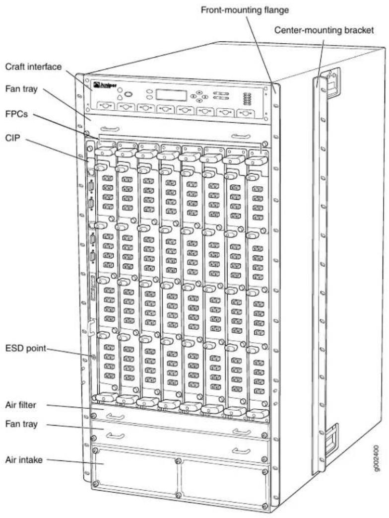
Figure 2: Rear View of the T1600 Router

Related Documentation
System Architecture Description for T Series Routers on page 6.
•T1600 Chassis Description on page 19
•General Safety Guidelines for Juniper Networks Devices on page 549
T1600 Component Redundancy
The T1600 Core Router is designed so that no single point of failure can cause the entire system to fail. The following major hardware components are redundant:
- Switch Interface Boards (SIBs)—The T1600 router has five SIBs.
See "T1600 Switch Interface Board (SIB) Description" on page 119.
- Host subsystem—The host subsystem consists of a Routing Engine functioning together with a control board. The router can have one or two host subsystems. If two host subsystems are installed, one functions as the master and the other functions as the
backup. If the master host subsystem (or either of its components) fails, the backup can take over as the master. To operate, each host subsystem requires a Routing Engine installed in an adjacent slot to a control board.
If the Routing Engines are configured for nonstop active routing, the backup Routing Engine automatically synchronizes its configuration and state with the master Routing Engine. Any update to the master Routing Engine state is replicated on the backup Routing Engine. If the backup Routing Engine assumes mastership, packet forwarding continues through the router without interruption. For more information about nonstop active routing, see the Junos OS High Availability Library for Routing Devices.

NOTE: Nonstop active routing is supported for standalone T1600 routers in Junos OS Release 8.5 and later. Nonstop active routing is supported for T1600 routers in a routing matrix in Junos OS Release 10.0 and later.
See "T1600 Host Subsystem Description" on page 41
- SONET Clock Generators (SCGs)—The router has a standard configuration of one SCG. A second can be purchased to function as backup. If one SCG fails, the other becomes the master SCG. Mastership of the SCGs is independent of the host subsystem, so routing functions are not affected.
See "T1600 SONET Clock Generators Description" on page 28.
- Power supplies—The router has two power supplies, which share the load evenly. If one power supply fails, the other power supply can provide full power to the router indefinitely.
See "T1600 Power System Description" on page 105.
- Cooling system—The cooling system has redundant components, which are controlled by the host subsystem. If one of the fans fails, the host subsystem increases the speed of the remaining fans to provide sufficient cooling for the router indefinitely.
See "T1600 Cooling System Description" on page 37.
Related Documentation
System Architecture Description for T Series Routers on page 6.
•T1600 Chassis Description on page 19
•T1600 Midplane Description on page 21
System Architecture Description for T Series Routers
The T Series Core Routers have two main architectural components:
- Routing Engine—One or more Routing Engines provide Layer 3 routing services and network management.
- Packet Forwarding Engines—These high-performance, ASIC-based components provide Layer 2 and Layer 3 packet switching, route lookups, and packet forwarding.
The Routing Engines and the Packet Forwarding Engines perform their primary tasks independently, although they constantly communicate through multiple 100 millions of packets per second (Mbps) links. This arrangement streamlines forwarding and routing control and runs Internet-scale backbone networks at high speeds. Figure 3 on page 7 shows the relationship between the Routing Engine and the Packet Forwarding Engines.
Figure 3: Router Architecture

flowchart
graph TD
    A["Packet In"] --> B["Packet Forwarding Engines"]
    B --> C["Packet Out"]
    D["Routing Engine"] <-->|100 Mbps links| B
Related Documentation
Routing Engine Functions for T Series Routers on page 7.
•Packet Forwarding Engine Architecture for T Series Routers on page 8
Routing Engine Functions for T Series Routers
The Routing Engine handles all routing protocol processes, as well as the software processes that control the router's interfaces, the chassis components, system management, and user access to the router. The routing and software processes run on top of a kernel that interacts with the Packet Forwarding Engine.
The Routing Engine constructs and maintains one or more routing tables (see Figure 4 on page 7). From the routing tables, the Routing Engine derives a table of active routes, called the forwarding table, which is then copied into the Packet Forwarding Engine. The design of the ASICs allow the forwarding table in the Packet Forwarding Engine to be updated without interrupting forwarding performance.
Figure 4: Control Packet Handling for Routing and Forwarding Table Updates

flowchart
graph TD
    A["Routing protocol process"] --> B["Routing Engine"]
    B --> C["Forwarding table"]
    C --> D["Packet Forwarding Engines"]
    D --> E["Packets out"]
    F["Packets in"] --> C
    G["Forwarding table updates"] --> C
    H["Routing protocol packets from network"] --> B
    I["1240"] --> D
The Routing Engine includes the following functions and features:
- Processing of routing protocol packets—The Routing Engine handles all packets that concern routing protocols, freeing the Packet Forwarding Engine to handle only packets that represent Internet traffic.
- Software modularity—Because each software process is devoted to a different function and uses a separate process space, the failure of one process has little or no effect on the others.
- In-depth Internet functionality—Each routing protocol is implemented with a complete set of Internet features and provides full flexibility for advertising, filtering, and modifying routes. Routing policies are set according to route parameters (for example, prefix, prefix lengths, and BGP attributes).
- Scalability—Junos OS routing tables have been designed to hold all the routes in current networks with ample capacity for expansion. Additionally, Junos OS can efficiently support large numbers of interfaces and virtual circuits.
- Management interface—Different levels of system management tools are provided, including the Junos OS command-line interface (CLI), the Junos XML management protocol, the craft interface, and SNMP.
- Storage and change management—Configuration files, system images, and microcode can be held and maintained in primary and secondary storage systems, permitting local or remote upgrades.
- Monitoring efficiency and flexibility—The router supports functions such as alarm handling and packet counting on every port, without degrading packet-forwarding performance.
Related Documentation
System Architecture Description for T Series Routers on page 6.
•Packet Forwarding Engine Architecture for T Series Routers on page 8
Packet Forwarding Engine Architecture for T Series Routers
The Packet Forwarding Engines provide the Layer 2 and Layer 3 packet switching, forwarding, and route lookup functions. The Packet Forwarding Engines are implemented in ASICs that are physically located on the FPCs and the PICs. To ensure the efficient movement of data, the router is designed so that ASICs on the hardware components handle the forwarding of data.
- Packet Forwarding Engine Components on page 9
• Data Flow on page 9
Packet Forwarding Engine Components
Each Packet Forwarding Engine consists of the following components:
- Layer 2/Layer 3 Packet Processing ASIC, which performs Layer 2 and Layer 3 encapsulation and decapsulation, and manages the division and reassembly of packets within the router.
- Queuing and Memory Interface ASICs, which manage the buffering of data cells in memory and the queueing of notifications.
• T Series Internet Processor, which provides the route lookup function. - Switch Interface ASICs, which extract the route lookup key and manage the flow of data cells across the switch fabric.
Media-specific ASICs on the PICs perform control functions tailored to the PIC media types.
Data Flow
To ensure the efficient movement of data, the router is designed so that ASICs on the hardware components handle the forwarding of data. Data flows through the router in the following sequence (see Figure 5 on page 9):
Figure 5: Data Flow Through the Router
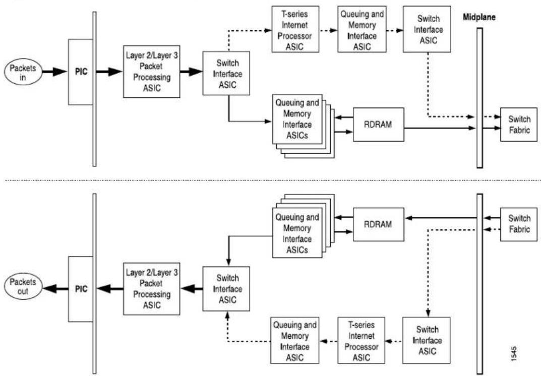
flowchart
graph TD
    A[" packets in "] --> B[" PIC "]
    B --> C[" Layer 2/Layer 3 Packet Processing ASIC "]
    C --> D[" Switch Interface ASIC "]
    D --> E[" T-series Internet Processor ASIC "]
    E --> F[" Queuing and Memory Interface ASIC "]
    F --> G[" Switch Interface ASIC "]
    G --> H[" Midplane "]
    D --> I[" Queuing and Memory Interface ASICs "]
    I --> J[" RDRAM "]
    J --> K[" Switch Fabric "]
    L[" Packets out "] --> M[" PIC "]
    M --> N[" Layer 2/Layer 3 Packet Processing ASIC "]
    N --> O[" Switch Interface ASIC "]
    O --> P[" Queuing and Memory Interface ASICs "]
    P --> Q[" RDRAM "]
    Q --> R[" Switch Interface ASIC "]
    R --> S[" Midplane "]
    P --> T[" T-series Internet Processor ASIC "]
    T --> U[" Switch Interface ASIC "]
    U --> V[" Switch Fabric "]
    W[" Packets in "] --> X[" PIC "]
    X --> Y[" Layer 2/Layer 3 Packet Processing ASIC "]
    Y --> Z[" Switch Interface ASIC "]
    Z --> AA[" Queuing and Memory Interface ASICs "]
    AA --> AB[" RDRAM "]
    AB --> AC[" Switch Fabric "]
    AD[" Packets out "] --> AE[" PIC "]
    AE --> AF[" Layer 2/Layer 3 Packet Processing ASIC "]
    AF --> AG[" Switch Interface ASIC "]
    AG --> AH[" Queuing and Memory Interface ASICs "]
    AH --> AI[" RDRAM "]
    AI --> AJ[" Switch Interface ASIC "]
    AJ --> AK[" Switch Fabric "]
- Packets arrive at an incoming PIC interface.
- The PIC passes the packets to the FPC, where the Layer 2/Layer 3 Packet Processing ASIC performs Layer 2 and Layer 3 parsing and divides the packets into 64-byte cells.
- The Switch Interface ASIC extracts the route lookup key, places it in a notification, and passes the notification to the T Series Internet Processor. The Switch Interface ASIC also passes the data cells to the Queuing and Memory Interface ASICs for buffering.
- The Queuing and Memory Interface ASICs pass the data cells to memory for buffering.
- The T Series Internet Processor performs the route lookup and forwards the notification to the Queuing and Memory Interface ASIC.
- The Queuing and Memory Interface ASIC sends the notification to the Switch Interface ASIC facing the switch fabric, unless the destination is on the same Packet Forwarding Engine. In this case, the notification is sent back to the Switch Interface ASIC facing the outgoing ports, and the packets are sent to the outgoing port without passing through the switch fabric (see Step 13).
- The Switch Interface ASIC sends bandwidth requests through the switch fabric to the destination port. The Switch Interface ASIC also issues read requests to the Queuing and Memory Interface ASIC to begin reading data cells out of memory.
- The destination Switch Interface ASIC sends bandwidth grants through the switch fabric to the originating Switch Interface ASIC.
- On receipt of each bandwidth grant, the originating Switch Interface ASIC sends a cell through the switch fabric to the destination Packet Forwarding Engine.
- The destination Switch Interface ASIC receives cells from the switch fabric. It extracts the route lookup key from each cell, places it in a notification, and forwards the notification to the T Series Internet Processor.
- The T Series Internet Processor performs the route lookup, and forwards the notification to the Queuing and Memory Interface ASIC.
- The Queuing and Memory Interface ASIC forwards the notification, including next-hop information, to the Switch Interface ASIC.
- The Switch Interface ASIC sends read requests to the Queuing and Memory Interface ASIC to read the data cells out of memory, and passes the cells to the Layer 2/Layer 3 Packet Processing ASIC.
- The Layer 2/Layer 3 Packet Processing ASIC reassembles the data cells into packets, adds Layer 2 encapsulation, and sends the packets to the outgoing PIC interface.
- The outgoing PIC sends the packets out into the network.
Related Documentation
•System Architecture Description for T Series Routers on page 6
•Routing Engine Functions for T Series Routers on page 7
CHAPTER 2
T1600 Router Release Notes
• Outstanding Issues with the T1600 Router on page 11
- Errata with the T1600 Router Documentation on page 12
Outstanding Issues with the T1600 Router
This topic lists outstanding hardware issues with the T1600 Core Router.
- To support the 10-Gigabit Ethernet LAN/WAN PIC with Oversubscription and SFP+ (model number PD-5-10XGE-SFPP) in the T1600-FPC4-ES (part number 710-013037), REV 13 and later is required.
T1600-FPC4-ES (part number 710-013037), REV 12 and earlier does not support the 10-Gigabit Ethernet LAN/WAN PIC with Oversubscription and SFP+ (model number PD-5-10XGE-SFPP).
- When the C8000-RE Routing Engine is installed, the LEDs for the ETHERNET ports on the connector interface panel (CIP) have the following issues:
- Model number RE-DUO-C1800-8G (part number 740-026941 Rev 7)—The activity LEDs, labeled ACT0 and ACT1, for the ETHERNET ports on the connector interface panel (CIP) are always steadily green, even when no cables are connected to the ports.
For RE-DUO-C1800-8G (part number 740-026941 Rev 8) and above, the CIP LED behavior is as described in the T1600 Core Router Hardware Guide.
- Model numbers RE-DUO-C1800-8G and RE-DUO-C1800-16G—The LEDs labeled GRN = 100M and YEL = 10M is always yellow, but the speed is always a 100-Mbps connection.
- After powering on or off a power supply, wait at least 60 seconds before turning it back off or on again.
- After a power supply is powered on, it can take up to 60 seconds for status indicators—such as LEDs on the power supply, show chassis commands, and messages on the craft interface LCD—to indicate that the power supply is functioning normally. Ignore error indicators that appear during the first 60 seconds.
- The external clock inputs on the SONET Clock Generators (SCGs) with DB-9 ports (model number SCG-T) are not supported.
- The external clock inputs on the SONET Clock Generators (SCGs) with RJ-45 ports (model number SCG-T-EC) are supported for JUNOS OS Release 10.4 and later.
For complete information about the router, see the T1600 Core Router Hardware Guide. For information about software issues, see the Junos OS Release Notes.
Related Documentation
Errata with the T1600 Router Documentation on page 12.
Errata with the T1600 Router Documentation
- The name of the T1600 Core Router PIC Guide has changed to T1600 Core Router Interface Module Reference. Some documentation references still refer to the T1600 Core Router PIC Guide.
- The verifying operation procedure in the T1600 Router Upgrade Guide incorrectly lists CB 0 REV 06 710-007655 KB9648 Control Board (CB-T) in the output.

NOTE: The control board shown as CB-T in the CLI output is the T640 standard control board (model number CB-L-T), which is not supported for T1600 routers, and is not the T-series control board (model number CB-T).
user@host> show chassis hardware Hardware inventory:
| Item | Version | Part number | Serial number | Description |
| Chassis | JN1090E5DAHA | T1600 | ||
| Midplane | REV 02 | 710-017247 | RC0094 | T640 Backplane |
| FPM GBUS | REV 09 | 710-002901 | WE0156 | T640 FPM Board |
| FPM Display | REV 05 | 710-021387 | DE4543 | T1600 FPM Display |
| CIP | REV 06 | 710-002895 | WD8691 | T-series CIP |
| PEM 0 | Rev 06 | 740-017906 | TE27790 | Power Entry Module |
| 3x80 | ||||
| PEM 1 | Rev 06 | 740-017906 | TE27779 | Power Entry Module |
| 3x80 | ||||
| SCG 0 | REV 14 | 710-003423 | WF1874 | T640 Sonet Clock Gen. |
| SCG 1 | REV 14 | 710-003423 | WF1881 | T640 Sonet Clock Gen. |
| Routing Engine 0 | REV 06 | 740-014082 | 1000688671 | RE-A-2000 |
| Routing Engine 1 | REV 06 | 740-014082 | 1000688739 | RE-A-2000 |
| CB 0 | REV 06 | 710-007655 | KB9648 | Control Board (CB-T) |
| CB 1 | REV 15 | 710-002728 | HR8130 | T-series Control Board |
The following output shows two control boards displayed as T-series Control Board.
user@host> show chassis hardware Hardware inventory:
| Item | Version | Part number | Serial number | Description |
| Chassis | JN1090E5DAHA | T1600 | ||
| Midplane | REV 02 | 710-017247 | RC0094 | T640 Backplane |
| FPM GBUS | REV 09 | 710-002901 | WE0156 | T640 FPM Board |
| FPM Display | REV 05 | 710-021387 | DE4543 | T1600 FPM Display |
| CIP | REV 06 | 710-002895 | WD8691 | T-series CIP |
| PEM 03x80 | Rev 06 | 740-017906 | TE27790 | Power Entry Module |
| PEM 13x80 | Rev 06 | 740-017906 | TE27779 | Power Entry Module |
| SCG 0 | REV 14 | 710-003423 | WF1874 | T640 Sonet Clock Gen. |
| SCG 1 | REV 14 | 710-003423 | WF1881 | T640 Sonet Clock Gen. |
| Routing Engine 0 | REV 06 | 740-014082 | 1000688671 | RE-A-2000 |
| Routing Engine 1 | REV 06 | 740-014082 | 1000688739 | RE-A-2000 |
| CB 0 | REV 15 | 710-002728 | HR8130 | T-series Control Board |
| CB 1 | REV 15 | 710-002728 | HR8131 | T-series Control Board |
| ... |
Related •Outstanding Issues with the T1600 Router on page 11 Documentation
CHAPTER 3
Chassis Components and Descriptions
• T1600 Hardware Component Overview on page 15
• T1600 Chassis Description on page 19
• T1600 Midplane Description on page 21
• T1600 Front Cable Management System Description on page 23
• T1600 Rear Cable Management System Description on page 23
• T1600 Connector Interface Panel (CIP) Description on page 25
• T1600 Connector Interface Panel (CIP) LEDs on page 27
• T1600 SONET Clock Generators Description on page 28
• T1600 SCG LEDs on page 30
• T1600 Craft Interface Description on page 31
• T1600 Craft Interface LCD and Navigation Buttons on page 32
• T1600 Craft Interface Alarm LEDs and ACO/LT Button on page 33
• T1600 Craft Interface Host Subsystem LEDs on page 34
• T1600 Craft Interface SIB LEDs on page 35
• T1600 Craft Interface FPC LEDs on page 35
T1600 Hardware Component Overview
The T1600 Core Router supports the components in Table 3 on page 15, listed in alphabetic order. The CLI Output column indicates the output as shown in the show chassis hardware command.
Table 3: T1600 Hardware Components
| Hardware Model NumberComponent | DescriptionCLI OutputHard | |||
| system | N/AN/AN/ACable management Front Cable Management System Description" on page 23"T1600 Rear Cable Management System Description" on page 23 | |||
| N/AN/AN/AChassis | “T1600 Chassis Description”on page 19 | |||
| Cooling system, including fan trays and air filters | ||||
| NoneFAN-REAR-TX-T640 Standard show fan chassishardware-models command. | “Tray00 Cooling System Description” on page 37 | |||
| LCC rear fan tray | NoneFAN-REAR-TXP-LCC | |||
| FAN-R-TXP-3D-LCC | ||||
| Quiet rear fan tray | FAN-R | REAR FANTRAYFAN-R-S | ||
| Quiet lower front fan tray | FAN-T-FBOT | FAN-T-FBOT-S andLOWER FANTRAY | ||
| Quiet upper front fan tray | FAN-T-FTOP | FAN-T-FTOP-S andUPPER FANTRAY | ||
| Front Fan Tray | FANTRAY-T4000 | |||
| Air filter kit | N/AN/AFLTR-KIT-T640 | |||
| Connector interface panel (CIP) | CIP-L-T640 | N/A | T-series CIP | “T1600 Connector Interface Panel (CIP) Description” on page 25 |
| Control board | “T1600 Control Boards Description” on page 66 | |||
| CB-T | Control Board-T | T-series Control Board | “T1600 T Series Control Boards (T-CBs) Description” on page 67 | |
| NOTE: CB-L-T is not supported. | NOTE: The control board shown as CB-T in the CLI output is the T640 Standard control board (model number CB-L-T), which is not supported for T1600 routers, and not the T-series control board (model number CB-T). | |||
| CB-LCC | Control Board | LCC Control Board | “T1600 Line-Card Chassis Control Board (LCC-CB) Description” on page 69 | |
| NOTE: CB-LCC is required for both RE-DUO-C1800-8G andRE-DUO-C1800-16G. | ||||
| T1600 FPM DisplayT1600CRAFT-T1600Craft interfaceDescription" on page 31 | ||||
| FPC | "T1600 FPCs Supported" on page 84 | See "T1600 Flexible PIC Concentrator (FPCT1600 Flexible PIC Description" on page 73. | "T1600 Flexible PIC Concentrator (FPC) Description" on page 73 | |
| including control board and Routing Engine | See control board and Routing Engine.Host subsystem, | "T1600 Host Subsystem Description" on page 41 | ||
| Midplane BackplaneN/AN/A1600 Midplane Description" on page 21 | ||||
| PIC | T1600 Core Router Interface Module Reference | NOTE: The output varies depending on the PIC. | "T1600 PIC Description" on page 86 | |
| Power system | "T1600 Power System Description" on page 105 | |||
| Three-phase delta AC power supply | PWR-T-10KW-DELTA-AC N/A | AC PEM 10kW US | "T1600 Three-Phase Delta and Wye AC Power Supply Description" on page 114 | |
| Three-phase wye AC power supply | PWR-T-10KW-WYE-AC N/A | AC PEM 10kW EMEA | "T1600 Three-Phase Delta and Wye AC Power Supply Description" on page 114 | |
| Three-Input 240-ADC Power Supply | PWR-T1600-3-80-DC N/A | Power Entry Module 3x80 | "T1600 Three-Input 240-A DC Power Supply Description" on page 106 | |
| Power Supply | Four-Input 240-A DZAPWR-T1600-4-60-DC Power Entry Module 4x60 | "T1600 Four-Input 240-A DC Power Supply Description" on page 109 | ||
| Supply | Six-Input DC PowerN/APWR-T-6-60-DC Power Entry Module 6x60 | "T1600 Six-Input DC Power Supply Description" on page 112 | ||
| "T1600 Routing Engine Description" on page 42Routing Engine | ||||
| N/ARE-600-2048 | RE-3.0 or RE-3.0(RE-600) | "T1600 RE-600 Description"on page 43 | ||
| RE-4.0 (RE-1600) | T1600-2048 Description"on page 45 | |||
| RE-A-2000N/ARE-A-2000 | T1600-2000 Description"on page 50 | |||
| N/ARE-DUO-C1800-8RE-TXP-LCC orRE-DUO-1800 | "T1600 RE-C1800Description" on page 47 | |||
| RE-DUO-C1800-16GNOTE: TheseRoutingEngines require theLCC-CB (modelnumber CB-LCC). | ||||
| SONET Clock Generator (SCG) | ||||
| SCG with RJ-48 portsSCG-T-EC | SONET CLOCK GENERATOR | T640 Sonet Clock Gen. | "T1600 SONET ClockGenerators Description" onpage 28 | |
| SCG with DB-9 ports SCG-T | SONET CLOCK GENERATOR | T640 Sonet Clock Gen. | ||
| Switch Interface Board (SIB) | "T1600 Switch Interface Board (SIB) Description" on page 119 | |||
| T1600-SIB | SIB-T1600 | Switch Interface Board 1600 | SIB-I8-SF | "T1600-SIB Description" onpage 120 |
| TXP-T1600 SIB | SIB-TXP-T1600 | SWITCH INTERFACE BOARD MULTICHASSIS | LCC SIB | "TXP-T1600 SIB Description"on page 121 |
| TXP-3D-LCC | SIB-TXP-3D-LCC | SWITCH INTERFACE BOARD MULTICHASSIS | LCC SIB | "TXP-T1600 SIB Description"on page 121 |
Related Documentation T1600 Router Description on page 3 • T1600 Field-Replaceable Units on page 301
T1600 Chassis Description
The T1600 Core Router chassis is a rigid sheet metal structure that houses all the other T1600 router components (see Figure 6 on page 20 and Figure 7 on page 21). The chassis measures 37.45 in. (95.1 cm) high, 31 in. (78.7 cm) deep, and 17.43 in. (44.3 cm) wide. The chassis can be installed into many types of racks or cabinets.
The chassis includes the following features (see Figure 6 on page 20 and Figure 7 on page 21):
- Front-mounting flanges for mounting in a four-post rack or cabinet or front-mounting in an open-frame rack.
- Center-mounting metal brackets for center-mounting in an open-frame rack.
- Handles on each side to facilitate positioning the router in the rack. Do not use the handles to lift the router.
- Two electrostatic discharge (ESD) points (banana plug receptacles), one front and one rear.

CAUTION: Before removing or installing components of a router, attach an ESD strap to an ESD point and place the other end of the strap around your bare wrist. Failure to use an ESD strap could result in damage to the router.

WARNING: The router must be connected to earth ground during normal operation.
Figure 6: Front View of Router Chassis

Figure 7: Rear View of Router Chassis
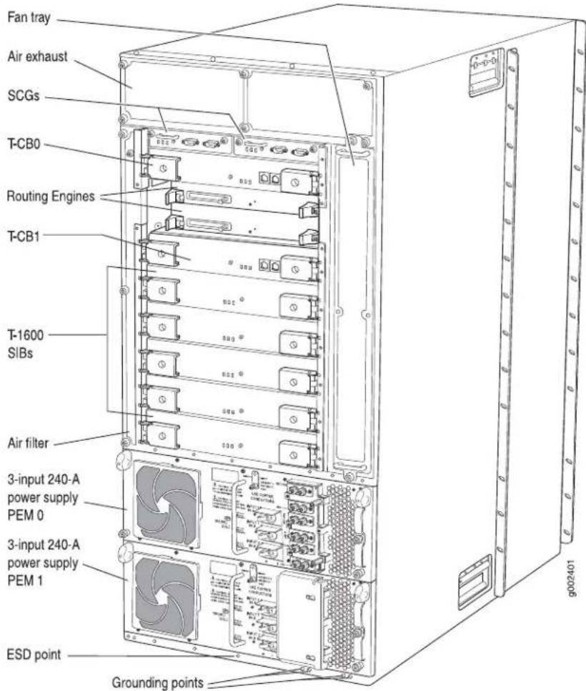
For chassis serial number information, see "Locating T1600 Component Serial Numbers Using the CLI" on page 531.
Related Documentation
T1600 Router Description on page 3.
•Rack Requirements for the T1600 Router on page 133
•Installing the T1600 Chassis in the Rack Manually on page 213
•Mounting the T1600 Chassis Using a Mechanical Lift on page 196
•General Safety Guidelines for Juniper Networks Devices on page 549
T1600 Midplane Description
The midplane is located in the center of the chassis and forms the rear of the FPC card cage (see Figure 8 on page 22). The FPCs install into the midplane from the front of the chassis, and the SIBs, Routing Engines, and control boards and SCGs install into the
midplane from the rear of the chassis. The power supplies and cooling system components also connect to the midplane.
The midplane performs the following major functions:
- Data path—Data packets are transferred across the midplane from the Packet Forwarding Engine on the originating FPC to the SIBs, and from the SIBs across the midplane to the Packet Forwarding Engine on the destination FPC.
See "Packet Forwarding Engine Architecture for T Series Routers" on page 8.
- Power distribution—The router power supplies are connected to the midplane, which distributes power to all the router components.
See "T1600 Power System Description" on page 105.
- Signal path—The midplane provides the signal path to the FPCs, SIBs, Routing Engines, CB, and other system components for monitoring and control of the system.
Figure 8: Midplane
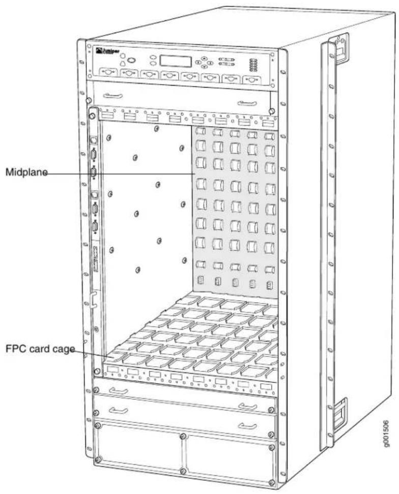
For chassis serial number information, see "Locating T1600 Component Serial Numbers Using the CLI" on page 531.
Related Documentation
T1600 Router Description on page 3.
T1600 Front Cable Management System Description
The front cable management system (see Figure 9 on page 23) consists of a row of nine semicircular plastic bobbins mounted on the front of the router below the FPC card cage. The PIC cables pass between the bobbins and into the tray, keeping the cables organized and securely in place. The curvature of the bobbins also helps maintain the proper bend radius for optical PIC cables.
You can pull the front cable management system up and outward to lock it into the maintenance position. This allows you to access the lower fan tray and the front air filter.
Figure 9: Front Cable Management System

natural_image
Technical line drawing of a mechanical support structure with multiple curved slots and mounting brackets (no text or symbols)Related Documentation
T1600 Chassis Description on page 19. •T1600 Rear Cable Management System Description on page 23
T1600 Rear Cable Management System Description

NOTE: The rear cable management system is not needed for standalone T1600 routers with T1600-SIBs and T-CBs.
For T1600 routers connected to a TX Matrix Plus router, you can use the optional rear cable management system to organize, support, and provide strain relief for the cables connected to the TXP-T1600 or TXP-LCC-3D SIBs, and the cables connected to the LCC-CBs. The rear cable management system consists of one cable management arm. The cables are routed to the left side of the T1600 router, and then toward the top of the chassis, where you can route the cables to the TX Matrix Plus router. The cable management system adds 9.5 in. (24.1 cm) to the depth of the T1600 chassis, and 2.4 in. (6.2 cm) to the left side of the chassis.
- The optional rear cable management system (model number CBL-MGR-TXP-LCC) supports the TXP-T1600 configuration and fiber-optic array cables only (see Figure 10 on page 24).
- The LCC rear cable management system (model number CBL-MGR-TXP-3D-LCC) can be used for any configuration including TXP-T1600 configuration, TXP-T1600-3D configuration, TXP-T4000-3D configuration, and TXP-Mixed-LCC-3D configuration.
See the TX Matrix Plus Router Hardware Guide for instructions on installing and using the T1600 rear cable management system.
Figure 10: T1600 Rear Cable Management System

Related T1600 Chassis Description on page 19. Documentation .T1600 Front Cable Management System Description on page 23
T1600 Connector Interface Panel (CIP) Description
• T1600 Connector Interface Panel (CIP) Components on page 25
• Management Ports on page 26
• T1600 Alarm Relay Contacts on page 27
T1600 Connector Interface Panel (CIP) Components
The Connector Interface Panel (CIP) consists of Ethernet, console, and auxiliary ports for the Routing Engines and alarm relay contacts (see Figure 11 on page 26).
Figure 11: CIP

The CIP is located at the left side of the FPC card cage, above the front electrostatic discharge point. The CIP is hot-pluggable.
Management Ports
The CIP has two sets of management ports (see Figure 11 on page 26) that you use to connect the Routing Engines to external management devices. The upper set of ports, labeled HOST 0, connects to the Routing Engine in slot RE0; and the lower set, labeled HOST 1, connects to the Routing Engine in slot RE1. From these management devices, you can use the CLI to configure the router.
Each set includes the following ports:
- ETHERNET—Connects the Routing Engine through an Ethernet connection to a management LAN (or any other device that plugs into an Ethernet connection) for out-of-band management. The port uses an autosensing RJ-45 connector to support both 10- and 100-Mbps connections.
- One small LED on the upper left edge of the ETHERNET port, labeled ACT, indicates whether traffic is passing through the port.
- One small LED on the lower left edge of the ETHERNET port indicates the connection in use: the yellow LED lights for a 10-Mbps connection, and the green LED lights for a 100-Mbps connection.

NOTE: When an RE-C18000 is installed, the connection LED is always yellow for both a 10-Mbps connection and 100-Mbps connection.
- CONSOLE—Connects the Routing Engine to a system console through an RS-232 (EIA-232) serial cable.
- AUXILIARY—Connects the Routing Engine to a laptop, modem, or other auxiliary device through an RS-232 (EIA-232) serial cable.
T1600 Alarm Relay Contacts
The CIP has two alarm relay contacts for connecting the router to external alarm devices (see Figure 11 on page 26). Whenever a system condition triggers either the red or yellow alarm on the craft interface, the alarm relay contacts are also activated. The alarm relay contacts are located below the Routing Engine ports. The terminal blocks that plug into the alarm relay contacts are supplied with the router. They accept wire of any gauge between 28-AWG and 14-AWG (0.08 and 2.08), which is not provided. Use the gauge of wire appropriate for the external device you are connecting.
Related Documentation
T1600 Connector Interface Panel (CIP) LEDs on page 27.
•T1600 Routing Engine Interface Cable and Wire Specifications on page 167
•T1600 RJ-45 Connector Pinouts for the Routing Engine ETHERNET Port on page 168
•T1600 DB-9 Connector Pinouts for the Routing Engine AUXILIARY and CONSOLE Ports on page 168
T1600 Connector Interface Panel (CIP) LEDs
Two small LEDs on the left edge of the ETHERNET port indicate activity and the speed of the connection in use. Table 4 on page 28 describes the functions of the LEDs.

NOTE: For routers with RE-C1800 Routing Engines, see the release notes for your router regarding more information about the LED behavior for the ETHERNET port.
Table 4: CIP LEDs
| DescriptionStateColorLED | |||
| ACT 0 and ACT1 | Green | On steadily | Traffic is passing through the port. |
| No traffic is passing through the port.Off-- | |||
| YEL= 10M | On steadilyGreenGRN = 100Mbps connection | ||
| On steadilyYellow | 10-Mbps connectionNOTE: When RE-C1800 Routing Engines are installed, the yellow LED indicates a 100-Mbps connection. | ||
| Off-- | Control board is offline. | ||
Related Documentation
Outstanding Issues with the T1600 Router on page 11
• T1600 Connector Interface Panel (CIP) Description on page 25
• T1600 RE-C1800 Description on page 47
- Connecting the T1600 Router to a Network for Out-of-Band Management on page 234
• T1600 LED Overview on page 504
T1600 SONET Clock Generators Description
The SONET Clock Generators (SCGs) provide 19.44-MHz Stratum 3 clock signal for the SONET/SDH interfaces on the router. One SCG is shipped as part of the standard router configuration, but up to two SCGs can be installed to provide redundancy. SCGs are installed into the upper rear of the chassis in the slots labeled SCGO and SCGI.
Backup SCGs are hot-removable and hot-insertable. Master and nonredundant SCGs are hot-pluggable.
The router supports the SCGs in Table 5 on page 29.

NOTE: Redundant SCGs must be the same model number, except during upgrade.
Table 5: Supported SCGs
| FirstSupported Junos OS ReleaseModel NumberNa | ||
| (Figure 12 on page 29) | 5.3SCG-TSCG with DB-9 ports | |
| (Figure 13 on page 29) | 10.4SCG-T-ECSCG with RJ-48 ports | |
Figure 12: SCG with DB-9 Ports

Figure 13: SCG with RJ-48 ports

Each SCG consists of the following components:
• 19.44-MHz Stratum 3 clock.
- Field-programmable gate array (FPGA) that performs multiplexing of clock sources.
These components are located on the SCG faceplate:
- Three LEDs—OK, FAIL, and MASTER, that display the status of the SCG.
• SCG online/offline button.
- Two external clock inputs.

NOTE: Junos OS Release 10.4 and later supports the external clock inputs on the SCG with RJ-48 ports. The external clock inputs are not supported on the SONET Clock Generator (SCG) with DB-9 ports.
For information about configuring external clock synchronization for T Series routers, see Junos OS Administration Library for Routing Devices
For information about configuring an interface transmit clock, see the Junos OS Network Interfaces Library for Routing Devices.
- Two LEDs for each RJ-48 external clock input that display the status of the links.
Related Documentation
T1600 SCG LEDs on page 30.
•Maintaining the T1600 SCGs on page 495
•Troubleshooting the T1600 SCGs on page 519
T1600 SCG LEDs
Three LEDs, located on the SCG faceplate, display the status of the SCG. Table 6 on page 31 describes the functions of the SCG LEDs. Two LINK LEDs, located on the left of each RJ-48 port, display the status of the external clock inputs links. The other LEDs on the right of each port are not used.

NOTE: The external clock inputs on the SCG with DB-9 ports are not functional.
Figure 14 on page 30 shows the LEDs on the SCG with RJ-48 ports.
Figure 14: SCG with RJ-48 ports

Table 6 on page 31 describes the functions of the SCG LEDs. The LINK LED is not applicable to the SCG with DB-9 ports.
Table 6: SCG LEDs
| DescriptionStateColorLabel | ||
| On steadilyGreenOKCG is online and is functioning normally. | ||
| Off | SCG is not online or not functioning normally. | |
| SCG has failed.On steadilyYellowFAIL | ||
| Off | SCG is offline or functioning normally. | |
| SCG is functioning as master.On steadilyBlueMA | ||
| Off | SCG is not functioning as the master. | |
| Link is online and active.On SteadilyGreenLINK | ||
| Off | No link. | |
Related Documentation
T1600 SONET Clock Generators Description on page 28
- Maintaining the T1600 SCGs on page 495
- Troubleshooting the T1600 SCGs on page 519
T1600 Craft Interface Description
The craft interface allows you to view status and troubleshooting information at a glance and to perform many system control functions. It is hot-insertable and hot-removable. The craft interface is located on the front of the T1600 Core Router above the FPCs (see Figure 15 on page 32).
The front panel of the craft interface contains:
- A four-line LCD display, along with six navigation buttons. The LCD display operates in Idle mode or alarm mode.
- Yellow Minor Alarm LED, Red Major Critical Alarm LED and alarm cutoff/lamp test ACO/LT button
- ONLINE/OFFLINE button for each FPC that you use to take the FPC offline and bring it online. The button is located next to the FPC LEDs on the bottom of the craft interface.
- Host Subsystem Master, OK, and FAIL LEDs
• SIB OK and FAIL LEDs
• FPC OK and FAIL LEDs for the fans
Figure 15: Front Panel of the Craft Interface
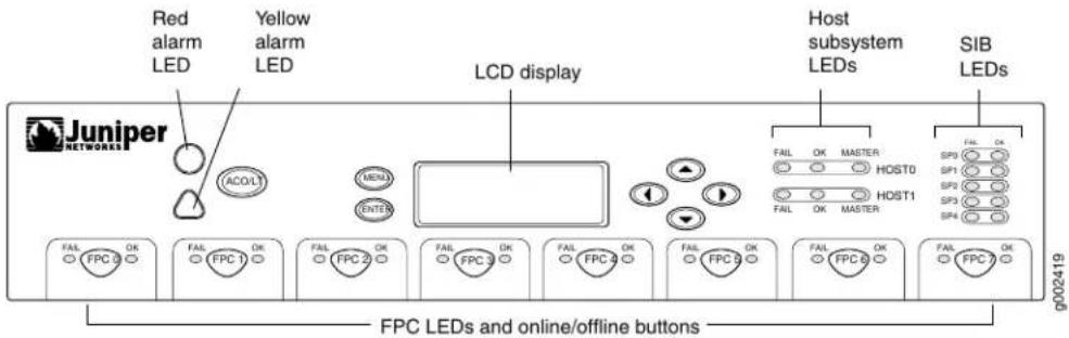
Related Documentation
• T1600 Craft Interface LCD and Navigation Buttons on page 32
• T1600 Craft Interface Alarm LEDs and ACO/LT Button on page 33
• T1600 Craft Interface Host Subsystem LEDs on page 34
• T1600 Craft Interface SIB LEDs on page 35
• T1600 Craft Interface FPC LEDs on page 35
- Troubleshooting the T1600 Craft Interface on page 510
T1600 Craft Interface LCD and Navigation Buttons
A four-line LCD is located in the craft interface, along with six navigation buttons. The LCD operates in two modes:
- LED idle mode
- LED alarm mode
During normal operation, the LCD operates in idle mode and reports current status information, as shown in Figure 16 on page 32.
Figure 16: LCD in Idle Mode

The lines in the display report the following information:
- First line—Router name.
- Second line—Length of time the router has been running, reported in the following form:
Up days + hours:minutes
- Third and fourth lines—Status messages, which rotate at 2-second intervals. Some conditions, such as removal or insertion of a system component, can interrupt the messages.
To add a message that alternates every 2 seconds with the default status messages, use the set chassis display message command. For more information, see set chassis display message.
When a red or yellow alarm occurs, the LCD switches to alarm mode and reports the alarm condition, as shown in Figure 17 on page 33.
Figure 17: LCD in Alarm Mode
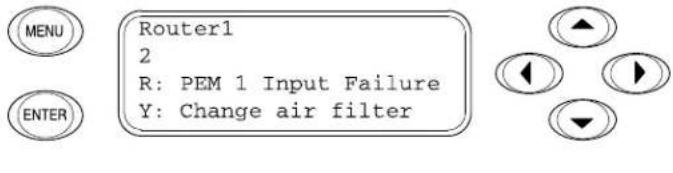
The lines in the display report the following information:
- First line—Router name.
• Second line—Number of active alarms. - Third and fourth lines—Individual alarm messages, with the most severe condition shown first. The prefix on each line indicates whether the alarm is a red (R) or yellow (Y) alarm.
Related Documentation
T1600 Craft Interface Description on page 31.
•T1600 LED Overview on page 504
•T1600 Alarm Messages Overview on page 506
T1600 Craft Interface Alarm LEDs and ACO/LT Button
Two large alarm LEDs are located at the upper left of the craft interface. The circular red LED lights to indicate a critical condition that can result in a system shutdown. The triangular yellow LED lights to indicate a less severe condition that requires monitoring or maintenance. Both LEDs can be lit simultaneously.
A condition that causes an LED to light also activates the corresponding alarm relay contact on the connector interface panel (CIP). The LCD on the craft interface reports the cause of the alarm.
To deactivate red and yellow alarms, press the button labeled ACO/LT (for "alarm cutoff/lamp test"), which is located to the right of the alarm LEDs. Deactivating an alarm turns off both LEDs and deactivates the device attached to the corresponding alarm relay contact on the CIP. However, the LCD continues to report the alarm message until you clear the condition that caused the alarm.
Table 7 on page 34 describes the alarm LEDs and alarm cutoff button in more detail.
Table 7: Alarm LEDs and Alarm Cutoff/Lamp Test Button
| DescriptionStateColorShape | |||
| On steadilyRed Critical alarm LED—Indicates a critical condition that can cause the router to stop functioning. Possible causes include component removal, failure, or overheating. | |||
| On steadilyYellow Warning alarm LED—Indicates a serious but nonfatal error condition, such as a maintenance alert or a significant increase in component temperature. | |||
| — | — | Alarm cutoff/lamp test button—Deactivates red and yellow alarms. Causes all LEDs on the craft interface to light (for testing purposes), when pressed and held. | |
Related Documentation
T1600 Craft Interface Description on page 31.
.T1600 Connector Interface Panel (CIP) Description on page 25
•T1600 Craft Interface LCD and Navigation Buttons on page 32
•T1600 Alarm Messages Overview on page 506
T1600 Craft Interface Host Subsystem LEDs
Each host subsystem has three LEDs, located on the upper right of the craft interface, that indicate its status. The LEDs labeled HOST0 show the status of the Routing Engine in slot RE0 and the CB in slot CB0. The LEDs labeled HOST1 show the status of the Routing Engine in slot RE1 and the CB in slot CB1. Table 8 on page 34 describes the functions of the host subsystem LEDs.
Table 8: T1600 Host Subsystem LEDs
| DescriptionStateColorLabel | |||
| FAOn steadilyRest is offline. | |||
| OK | Green | On steadily | Host is online and is functioning normally. |
| MASTER | Green | On steadily | Host is functioning as the master. |
Related Documentation
T1600 Host Subsystem Description on page 41
•T1600 Craft Interface Description on page 31
•T1600 T-CB LEDs on page 68
•T1600 RE-600 LEDs on page 45
•T1600 RE-1600 LEDs on page 47
•T1600 RE-2000 LEDs on page 51
•T1600 LED Overview on page 504
T1600 Craft Interface SIB LEDs
Each SIB has two LEDs on the craft interface that indicate its status. The SIB LEDs, labeled SIB0 through SIB2, are located on the upper right of the craft interface. The ACTIVE LED on the SIB faceplate is not replicated on the craft interface. Table 9 on page 35 describes the functions of the SIB LEDs.
Table 9: SIB LEDs on the Craft Interface
| DescriptionStateColorLabel | |||
| SIB has failed.On steadilyRedFAIL | |||
| SIB is functioning normally.On steadilyGreenOK |
Related Documentation
T1600 Switch Interface Board (SIB) Description on page 119.
•T1600 Craft Interface Description on page 31
- Maintaining the T1600 SIBs on page 495
•Troubleshooting the T1600 SIBs on page 520
T1600 Craft Interface FPC LEDs
Each FPC slot has two LEDs that indicate its status. The FPC LEDs, labeled FPC0 through FPC7, are located along the bottom of the craft interface. Table 10 on page 35 describes the functions of the FPC LEDs.
Table 10: FPC LEDs
| DescriptionStateColorLabel | ||
| On steadilyFEDFA has failed. | ||
| On steadilyFREeinkunctioning normally. | ||
| Blinking FPC is starting up. | ||
Related Documentation
•T1600 Flexible PIC Concentrator (FPC) Description on page 73
•T1600 Craft Interface Description on page 31
•Maintaining T1600 FPCs on page 480
•Troubleshooting the T1600 FPCs on page 515
CHAPTER 4
Cooling System Components and Descriptions
• T1600 Cooling System Description on page 37
T1600 Cooling System Description
The cooling system components work together to keep all router components within the acceptable temperature range. The host subsystem monitors the temperature of the router components. When the router is operating normally, the fans function at lower than full speed. If a fan fails or the ambient temperature rises above a threshold, the speed of the remaining fans is automatically adjusted to keep the temperature within the acceptable range. If the ambient maximum temperature specification is exceeded and the system cannot be adequately cooled, the Routing Engine shuts down some or all of the hardware components.
- Airflow on page 37
• Fan Trays on page 38
• Air Filters on page 40
• Power Supply Cooling System on page 40
Airflow
Figure 18 on page 38 shows the airflow through the router.
Figure 18: Airflow Through the Chassis

Fan Trays

NOTE: The standard fan trays and quiet fan trays are not interchangeable with each other. All fans in the chassis must be either standard fan trays or quiet fan trays.
The cooling system contains the following fan trays:
- One rear fan tray cools the components installed in the rear card cage (the Routing Engines, control boards, SCGs, and SIBs). The T1600 router supports the following rear fan trays:
- The standard rear fan tray, supported by Junos OS 8.5 and later, contains eight fans. It has no label and is not interchangeable with the standard front fan trays.
- The quiet rear fan tray, labeled REAR FANTRAY FAN-R-S and supported by Junos OS 11.1 and later, contains eight fans and is not interchangeable with the quiet front fan trays.
- One upper front fan tray and one lower front fan tray that cool the components installed in the front card cage (the FPCs, PICs, CIP, and midplane). The T1600 router supports the following front fan trays:
- The upper and lower standard front fan trays, each of which contains six fans and has no labels. Both standard fan trays are interchangeable with each other.
- Each quiet front fan tray contains four fans, as indicated by the four fan icons on the faceplate, and is supported by Junos OS 11.1 and later.

NOTE: The quiet upper front fan tray and quiet lower front fan tray are not interchangeable with each other. In addition to the labels, the quiet upper fan tray also has an upward pointing arrow above the four fan icons on the faceplate.
The quiet upper front fan tray is labeled FAN-T-FTOP-S and UPPER FANTRAY (see Figure 19 on page 39).
Figure 19: Quiet Upper Front Fan Tray

The quiet lower front fan tray is labeled FAN-T-FBOT-S and LOWER FANTRAY (see
Figure 20: Quiet Lower Front Fan Tray

- To upgrade from a standalone T1600 router or from a T1600 LCC with TXP-T1600 SIBs, the FANTRAY-T4000 front fan trays are required. The rear fan tray (model number FAN-R-TXP-3D-LCC) contains 16 fans and is required for LCCs with TXP-LCC-3D SIBs (see Figure 21 on page 39). The FANTRAY-T4000 front fan tray and FAN-R-TXP-3D-LCC rear fan tray are supported in Junos 13.1 and later.
Figure 21: Rear Fan Tray (FAN-R-TXP-3D-LCC)

natural_image
Technical line drawing of a rectangular electronic component with mounting flanges (no text or symbols)All fan trays are hot-insertable and hot-removable.
Air Filters
The cooling system contains a front air filter and a rear air filter. All air filters are hot-insertable and hot-removable.
Power Supply Cooling System
The power supply cooling system consists of the following:
• Each DC power supply contains one fan that cools that power supply.
• Each AC power supply contains two fans that cool that power supply.
Related Documentation
•Clearance Requirements for Airflow and T1600 Hardware Maintenance on page 135
- Maintaining the T1600 Air Filters on page 476
- Maintaining the T1600 Air Intake Vents on page 476
- Maintaining the T1600 Fan Trays on page 478
•Troubleshooting the T1600 Cooling System on page 507
•T1600 Physical Specifications on page 131
CHAPTER 5
Host Subsystem Components and Descriptions
• T1600 Host Subsystem Description on page 41
• T1600 Routing Engine Description on page 42
• T1600 RE-600 Description on page 43
• T1600 RE-600 LEDs on page 45
• T1600 RE-1600 Description on page 45
• T1600 RE-1600 LEDs on page 47
• T1600 RE-C1800 Description on page 47
• T1600 RE-C1800 LEDs on page 49
• T1600 RE-2000 Description on page 50
• T1600 RE-2000 LEDs on page 51
- Routing Engine Specifications on page 52
• Supported Routing Engines by Router on page 55
• T1600 Control Boards Description on page 66
• T1600 T Series Control Boards (T-CBs) Description on page 67
• T1600 T-CB LEDs on page 68
• T1600 Line-Card Chassis Control Board (LCC-CB) Description on page 69
• T1600 LCC-CB LEDs on page 70
T1600 Host Subsystem Description
The host subsystem provides the routing and system management functions of the router. You can install one or two host subsystems on the router. The host subsystem consists of a Routing Engine and an adjacent control board. To operate, each host subsystem functions as a unit; the Routing Engine requires the corresponding control board, and vice versa.

NOTE: We recommend that you install two host subsystems for redundant protection. If you install only one host subsystem, we recommend that you install it in slots REO and CBO.
Each host subsystem has three LEDs, located on the upper right of the craft interface, that display its status. In addition, there are LEDs on each Routing Engine and control board.
Related Documentation
T1600 Routing Engine Description on page 42.
•T1600 Control Boards Description on page 66
•T1600 Craft Interface Host Subsystem LEDs on page 34
T1600 Routing Engine Description
The Routing Engine runs Junos OS. Software processes that run on the Routing Engine maintain the routing tables, manage the routing protocols used on the T1600 Core Router, control the T1600 router interfaces, control some chassis components, and provide the interface for system management and user access to the router.
You can install one or two Routing Engines in the router. The Routing Engines install into the upper rear of the chassis in the slots labeled RE0 and RE1. Each Routing Engine requires a control board to be installed in the adjacent slot. RE0 installs below CBO, and RE1 installs above CB1. A Routing Engine does not power up without a control board present in the adjacent slot.
If two Routing Engines are installed, one functions as the master and the other acts as the backup. If the master Routing Engine fails or is removed and the backup is configured appropriately, the backup takes over as the master. If the host system is redundant, the backup Routing Engine is hot-removable and hot-insertable, but the master Routing Engine is hot-pluggable. A Routing Engine that is not redundant requires that you power down the router before replacement.

NOTE: For specific information about Routing Engine components (for example, the amount of DRAM), issue the show chassis routing-engine command.
The ports for connecting the Routing Engine to external management devices are located on the Connector Interface Panel (CIP).

NOTE: If two Routing Engines are installed, they must both be the same hardware model, except during upgrade.
The T1600 router supports the Routing Engines listed in Table 11 on page 43
Table 11: T1600 Supported Routing Engines
| FirstSupported Junos OS ReleaseModel NumberN | ||
| 8.5RE-600-2048RE-600 (EOL) | ||
| "T1600 RE-600 Description" on page 43 | ||
| 8.5RE-1600-2048RE-1600 (EOL) | ||
| "T1600 RE-1600 Description" on page 45 | ||
| 8.5RE-A-2000-4096RE-2000 | ||
| "T1600 RE-2000 Description" on page 50 | ||
| RE-DUO-C1800-8GRE-C1800R2 for routers in a routing matrix | ||
| "T1600 RE-C1800 Description" on page 47 | 11.1 for standalone T1600 routers. | |
| NOTE: The RE-C1800 is required for connection to a TX Matrix Plus router. | 11.4R2RE-DUO-C1800-16G | |
| These Routing Engines require the LCC-CB. | ||
Related Documentation
Routing Engine Functions for T Series Routers on page 7.
• T1600 Hardware Component Overview on page 15
- Maintaining the T1600 Routing Engines on page 486
T1600 RE-600 Description
The RE-600 boots from the storage media in this order: the PC Card (if present), then the CompactFlash card (if present), then the hard disk.
Figure 22: Routing Engine 600

Each Routing Engine 600 (shown in Figure 22 on page 43) consists of the following components:
- CPU—Runs Junos OS to maintain the router's routing tables and routing protocols. It has a Pentium-class processor.
- SDRAM—Provides storage for the routing and forwarding tables and for other Routing Engine processes.
- CompactFlash card—Provides primary storage for software images, configuration files, and microcode. The fixed CompactFlash card is inaccessible from outside the router.
- Hard disk—Provides secondary storage for log files, memory dumps, and rebooting the system if the CompactFlash card fails.
- EEPROM—Stores the serial number of the Routing Engine.
- Interfaces for out-of-band management access—Provide information about Routing Engine status to devices (console, laptop, or terminal server) connected to ports located on the Connector Interface Panel (CIP).

NOTE: The router's management Ethernet interface fxp0 is the interface for connecting network devices to the router through the ETHERNET port on the connector interface panel (CIP). Junos OS automatically creates fxp0, but you must configure its logical interface, fxp0.0, with a valid IP address before you can use fxp0 as a management port.
The faceplate of the Routing Engine 600 contains the following:
- One PC Card slot—Accepts a removable PC Card, which stores software images for system upgrades.
A slot labeled PC CARD on the Routing Engine faceplate accepts a Type I PC Card, as defined in the PC Card Standard published by the Personal Computer Memory Card International Association (PCMCIA). The TX Matrix router is shipped with a PC Card that contains Junos OS. The PC Card can be used to copy Junos OS from the PC Card onto the Routing Engine. You can also copy Junos OS from the Routing Engine onto a PC Card, for example, to create a backup copy of upgrade software that you have obtained from Juniper Networks. Instructions for copying software to a PC Card are available at the Juniper Networks Support Web site (http://www.juniper.net/support/);
after logging in, navigate to the Customer Support Center, then to the download page for Junos OS.

NOTE: The software on a PC Card is loaded only onto the Routing Engine into which the PC Card is inserted. It is not automatically copied to the other Routing Engine.
- Reset button—Reboots the Routing Engine when pressed.
- HD LED.
Related Documentation
T1600 Routing Engine Description on page 42.
.T1600 RE-600 LEDs on page 45
- Maintaining the T1600 Host Subsystem on page 486
- Maintaining the T1600 Routing Engines on page 486
•Troubleshooting the T1600 Host Subsystems on page 510
T1600 RE-600 LEDs
The HD LED indicates activity on the hard drive. It does not necessarily indicate routing-related activity.

NOTE: The LEDs that report host module status (including Routing Engine status) are on the craft interface rather than the Routing Engine faceplate.
Related Documentation
T1600 Routing Engine Description on page 42.
.T1600 RE-600 Description on page 43
- Maintaining the T1600 Host Subsystem on page 486
- Maintaining the T1600 Routing Engines on page 486
•Troubleshooting the T1600 Host Subsystems on page 510
T1600 RE-1600 Description
The RE-1600 boots from the storage media in this order: the PC Card in SLOT 0 (if present), then the PC Card in SLOT1 (if present), then the CompactFlash card (if present), then the hard disk.
Figure 23: Routing Engine 1600 (RE-1600)
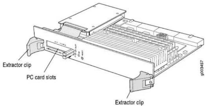
Each RE-1600 (shown in Figure 23 on page 45) consists of the following components:
- CPU—Runs Junos OS to maintain the router's routing tables and routing protocols. It has a Pentium-class processor.
- SDRAM—Provides storage for the routing and forwarding tables and for other Routing Engine processes.
- CompactFlash card—Provides primary storage for software images, configuration files, and microcode. The CompactFlash card is inaccessible from outside the router.
- Hard disk—Provides secondary storage for log files, memory dumps, and rebooting the system if the CompactFlash card fails.
- EEPROM—Stores the serial number of the Routing Engine.
- Interfaces for out-of-band management—Provide information about Routing Engine status to devices (console, laptop, or terminal server) connected to the Routing Engine ports located on the CIP.

NOTE: The router's management Ethernet interface fxp0 is the interface for connecting network devices to the router through the ETHERNET port on the connector interface panel (CIP). Junos OS automatically creates fxp0, but you must configure its logical interface, fxp0.0, with a valid IP address before you can use fxp0 as a management port.
The faceplate of the RE-1600 contains the following:
- Two PC Card slots—Accept removable PC Cards, which store software images for system upgrades.
Each PC Card slot accepts a Type I PC Card, as defined in the PC Card Standard published by the Personal Computer Memory Card International Association (PCMCIA). The TX Matrix router is shipped with a PC Card that contains Junos OS. The PC Card can be used to copy Junos OS from the PC Card onto the Routing Engine. You can also copy Junos OS from the Routing Engine onto a PC Card, for example, to create a backup copy of upgrade software that you have obtained from Juniper Networks. Instructions for copying software to a PC Card are available at the Juniper Networks Support Web site (http://www.juniper.net/support/); after logging in, navigate to the Customer Support Center, then to the download page for Junos OS.

NOTE: The software on a PC Card is loaded only onto the Routing Engine into which the PC Card is inserted. It is not automatically copied to the other Routing Engine.
- Reset button—Reboots the Routing Engine when pressed.
- LEDs—HD and Slot LEDs 0 and 1—indicate activity on the hard drive or PC Cards.

NOTE: The LEDs on the Routing Engine do not necessarily indicate routing-related activity.

NOTE: The LEDs that report host module status (including Routing Engine status) are on the craft interface rather than the Routing Engine faceplate.
Related Documentation
T1600 Routing Engine Description on page 42.
•T1600 RE-1600 LEDs on page 47
- Maintaining the T1600 Host Subsystem on page 486
- Maintaining the T1600 Routing Engines on page 486
•Troubleshooting the T1600 Host Subsystems on page 510
T1600 RE-1600 LEDs
Table 12 on page 47 describes the functions of these LEDs.
Table 12: RE-1600 LEDs
| DescriptionStateColorLabel | |||
| YellowHD | blinking | Indicates activity on the hard drive.On steadily or | |
| Slot LEDs 0 and 1 | green alternately | BlinkingRed and | Indicates that the Routing Engine is booting and the firmware is checking if a PC card is installed. |
| Indicates that the Routing Engine booted from the PC Card.On steadily |
Related Documentation
T1600 Routing Engine Description on page 42.
•T1600 RE-1600 Description on page 45
- Maintaining the T1600 Host Subsystem on page 486
- Maintaining the T1600 Routing Engines on page 486
•Troubleshooting the T1600 Host Subsystems on page 510
T1600 RE-C1800 Description

NOTE: These Routing Engines require the LCC-CB.
• RE-C1800 Components on page 48
• RE-C1800 Boot Order on page 49
RE-C1800 Components
Each RE-C1800 (Figure 24 on page 48) consists of the following components:
- CPU—Runs Junos OS to maintain the routing tables and routing protocols.
- DRAM—Provides storage for the routing and forwarding tables and for other Routing Engine processes.
- EEPROM—Stores the serial number of the Routing Engine.
- Interfaces for management access—Provide information about Routing Engine status to devices (console, laptop, or terminal server) connected to the management ports located on the CIP.

NOTE: The router's management Ethernet interface em0 is the interface for connecting network devices to the router through the ETHERNET port on the connector interface panel (CIP). Junos OS automatically creates em0, but you must configure its logical interface, em0.0, with a valid IP address before you can use em0 as a management port.
Figure 24: RE-C1800

The faceplate of the RE-C1800 contains the following:
- USB port—Provides a removable media interface through which you can install Junos OS manually. Junos OS supports USB version 1.1 and version 2.0 devices.
- CompactFlash card slot—Provides primary storage for software images, configuration files, and microcode.
- Two solid-state disk (SSD) slots—Provides secondary storage for log files, memory dumps, and rebooting the system if the CompactFlash card fails.

NOTE: DISK2 is not currently supported.
- Reset button—Reboots the Routing Engine when pressed.
- Offline button—Takes the Routing Engine offline when pressed.
• Four LEDs—CF, ONLINE, ONLINE, and ONLINE. - Extractor clips—Control the locking system that secures the Routing Engine.
RE-C1800 Boot Order
The RE-C1800 Routing Engine boots from the storage media in this order: the USB device, then the CompactFlash card (if present), then DISK1, then the LAN.
Related Documentation
T1600 Routing Engine Description on page 42.
.T1600 RE-C1800 LEDs on page 49
•T1600 Line-Card Chassis Control Board (LCC-CB) Description on page 69
- Maintaining the T1600 Host Subsystem on page 486
- Maintaining the T7600 Routing Engines on page 486
•Troubleshooting the T1600 Host Subsystems on page 510
T1600 RE-C1800 LEDs
Figure 25 on page 49 shows the RE-C1800 LEDs. Table 13 on page 49 describes the functions of the LEDs on the faceplate of the Routing Engine.
Figure 25: RE-C1800 LEDs


NOTE: The LEDs on the Routing Engine do not necessarily indicate routing-related activity.
Table 13: Routing Engine C1800 LEDs
| DescriptionStateColorLabel | |||
| CF | Green | On steadily | Indicates disk activity on the CompactFlash card. |
| — | Off | There is no disk activity on the CompactFlash card. |
Table 13: Routing Engine C1800 LEDs (continued)
| DescriptionStateColorLabel | |||
| Indicates activity for the disk.On steadilyGreenDISK1 | |||
| There is no activity for the disk.Off— | |||
| Not applicable.On steadilyGreenDISK2 | |||
| — | Off | NOTE: The DISK2 LEDis not currently supported. | |
| Routing Engine is functioning normally.On steadilyGreenONLIN | |||
| On steadilyReRouting Engine is not functioning normally. | |||
| — | Off | Routing Engine is not online or not functioning normally. | |
| USB | Green | On steadily | Indicates activity on the USB port. |
| — | Off | There is no activity on the USB port. | |
Related Documentation
T1600 Routing Engine Description on page 42
• T1600 RE-C1800 Description on page 47
- Maintaining the T1600 Host Subsystem on page 486
- Maintaining the T1600 Routing Engines on page 486
- Troubleshooting the T1600 Host Subsystems on page 510
T1600 RE-2000 Description
The RE-2000 boots from the storage media in this order: the USB device, then the CompactFlash card (if present), then the hard disk, then the LAN.
Figure 26: Routing Engine 2000 (RE-2000)

Each RE-2000 (shown in Figure 26 on page 50) consists of the following components:
- CPU—Runs Junos OS to maintain the routing tables and routing protocols. It has a Pentium-class processor.
- DRAM—Provides storage for the routing and forwarding tables and for other Routing Engine processes.
- CompactFlash card—Provides primary storage for software images, configuration files, and microcode. The CompactFlash card is inaccessible from outside the router.
- Hard disk—Provides secondary storage for log files, memory dumps, and rebooting the system if the CompactFlash card fails.
- EEPROM—Stores the serial number of the Routing Engine.
- Interfaces for out-of-band management access—Provide information about Routing Engine status to devices (console, laptop, or terminal server) connected to the Routing Engine ports located on the CIP.

NOTE: The router's management Ethernet interface fxp0 is the interface for connecting network devices to the router through the ETHERNET port on the connector interface panel (CIP). Junos OS automatically creates fxp0, but you must configure its logical interface, fxp0.0, with a valid IP address before you can use fxp0 as a management port.
The faceplate of the RE-2000 contains the following:
- USB port—Provides a removable media interface through which you can install Junos OS manually. Junos OS supports USB version 1.0.
- Reset button—Reboots the Routing Engine when pressed.
- Offline button—Takes the Routing Engine offline when pressed.
- Extractor clips—Control the locking system that secures the Routing Engine.
- LEDs—HDD and ONLINE indicate activity on the hard disk drive and the status of the Routing Engine.
Related Documentation
T1600 Routing Engine Description on page 42.
•T1600 RE-2000 LEDs on page 51
- Maintaining the T1600 Host Subsystem on page 486
- Maintaining the T1600 Routing Engines on page 486
•Troubleshooting the T1600 Host Subsystems on page 510
T1600 RE-2000 LEDs
Table 14 on page 52 describes the functions of the LEDs on the faceplate of the Routing Engine.

NOTE: The LEDs on the Routing Engine do not necessarily indicate routing-related activity.
Table 14: Routing Engine 2000 LEDs
| DescriptionStateColorLabel | |||
| Indicates disk activity for the hard disk drive.On steadilyBlue | |||
| Routing Engine is functioning normally.On steadilyGreenONLIM | |||
| Routing Engine is transitioning online.Blinking | |||
| On steadilyRedRouting Engine has failed. |
Related Documentation
T1600 Routing Engine Description on page 42
• T1600 RE-2000 Description on page 50
- Maintaining the T1600 Host Subsystem on page 486
- Maintaining the T1600 Routing Engines on page 486
- Troubleshooting the T1600 Host Subsystems on page 510
Routing Engine Specifications
Table 15 on page 52 lists the current specifications for Routing Engines supported on PTX Series Packet Transport Routers, and M Series, MX Series, and T Series routers. Table 16 on page 54 lists the specifications for end-of-life Routing Engines.
Table 15: Routing Engine Specifications
| Routing Engine | Processor | Memory | Connection to PFEs | Disk | Media | First Junos OS Support |
| RE-400-768 | 400-MHz Celeron | 768 MB | Fast Ethernet | 40 GB Hard disk | 1 GB CompactFlash card | 9.0 |
| RE-A-1000-2048 | 1.0-GHz Pentium | 2048 MB | Gigabit Ethernet | 40 GB Hard disk | 1 GB CompactFlash card | 8.1 |
| RE-A-2000-4096 | 2.0-GHz Pentium | 4096 MB | Gigabit Ethernet | 40 GB Hard disk | 1 GB CompactFlash card | 8.1 |
| RE-S-1300-2048 | 1.3-GHz Pentium | 2048 MB | Gigabit Ethernet | 40 GB Hard disk | 1 GB CompactFlash card | 8.2 |
| Routing Engine | Connection to PFEsMemoryProcessor | First Junos OS SupportMediaDisk | ||||
| RE-S-2000-4096 Pentium | 4096 MB2.0-GHzGigabit Ethernet | 40 GB Hard disk | CompactFlash card | 8.21 GB | ||
| 8 GB1.8-GHzRE-C1800 Ethernet | SSDGigabit | 4 GB CompactFlash card | T1600 router in a routing matrix: 9.6R2 Standalone T640 or T1600 router:11.2 | |||
| 16 GB2.6-GHzRE-C2600 Ethernet | SSDGigabit | 4 GB CompactFlash card | TX Matrix Plus router: 9.6R2 PTX5000 Packet Transport Router: 12.1x48 | |||
| RE-A-1800x2 | 1800-MHz | 8 GB or 16 GB Gigabit Ethernet | 32 GB SSD | 4 GB CompactFlash card | 10.4 | |
| RE-S-1800x2 | 1800-MHz | 8 GB or 16 GB Gigabit Ethernet | 32 GB SSD | 4 GB CompactFlash card | 10.4 | |
| RE-S-1800x4 | 1800-MHz | 8GB or 16 GB Gigabit Ethernet | 32 GB SSD | 4 GB CompactFlash card | 10.4 | |
| 4 GB1.8-GHzRE-GigabitO4 Ethernet | - | 8 GB NAND Flash | 13.2 | |||
| RE-B-1800x1-4GGB1.73-GHz | Gigabit Ethernet | 64 GB SSD | 4 GB CompactFlash card | 12.1R2, 11.4R4, and 12.2R1 | ||
| RE-MX2000-1800x4GB1800-GHz | Gigabit Ethernet | - | 4 GB Fixed Internal CompactFlash card | 12.3R2 | ||
| RES-1800X4-3ZGS | 1800 Ghz | 32 GB | Gigabit Ethernet | 32 GB SSD | 4 GB Fixed Internal CompactFlash card | • 12.3R4 • 13.2R1 |
| REMXK-1800-3ZGS | 1800 Ghz | 32 GB | Gigabit Ethernet | - | 4 GB Fixed Internal CompactFlash card | • 12.3R4 • 13.2R1 |
Table 16: End-of-Life Routing Engine Specifications
| Routing Engine | Connection to PFEs | MemoryProcessor | First Junos OS SupportMediaDisk | EOL Details | |||
| RE-333-256 | Pentium II | 256 MB333-MHz | Ethernet | 6.4 GB Hard disk | CompactFlash card | 3.480 MB | PSN-2003-01-063 |
| RE-333-768 | Pentium II | 768 MB333-MHz | Ethernet | 6.4 GB Hard disk | CompactFlash card | 3.480 MB | PSN-2003-01-063 |
| RE-600-512 | Pentium III | 512 MB600-MHz | Ethernet | 30 GB Hard disk | CompactFlash card | 5.4256 MB | PSN-2004-07-019 |
| RE-600-2048 | Pentium III | 2048 MB600-FHz | Ethernet | 40 GBHard disk | CompactFlash card | 5.31 GB | PSN-2008-02-018 |
| RE-850-1536 | 850-MHz Pentium III | 1536 MB Fast Ethernet | Ethernet | 40 GB Hard disk | CompactFlash card | 7.21 GB | PSN-2011-04-226 |
| RE-M40 | Pentium | 256 MB200-MHz | Ethernet | 6.4 GB Hard disk | 80 MB CompactFlash card | 3.2 | FA-HW-0101-001 |
| REM40-333-768 | Pentium II | 768 MB333-MHz | Ethernet | 10 GB Hard disk | CompactFlash card | 4.280 MB | PSN-2003-01-063 |
| REM40-600-2048 | Pentium III | 2048 MB600-FHz | Ethernet | 30 GB Hard disk | CompactFlash card | 5.4128 MB | PSN-2004-TI-020 |
| RE-1600-2048 | Pentium M | 2048 MB1.6-GHz | Ethernet | 40 GB Hard disk | 1 GB CompactFlash card | 6.2 | PSN-2008-02-019 |

NOTE: The memory in Table 15 on page 52 indicates the amount of total memory. To determine the amount of available memory, issue the show chassis routing-engine CLI command.
On routing platforms that accept two Routing Engines, you cannot mix Routing Engine types except for a brief period (one minute or so) during an upgrade or downgrade to two Routing Engines of the same type.
Related Documentation
Supported Routing Engines by Router on page 55
Supported Routing Engines by Router
The following tables list the Routing Engines that each router supports, the first supported release for the Routing Engine in the specified router, the management Ethernet interface, and the internal Ethernet interfaces for each Routing Engine.
• M7i Supported Routing Engines on page 55
• M10i Supported Routing Engines on page 56
• M40e Supported Routing Engines on page 56
• M120 Supported Routing Engines on page 57
• M320 Supported Routing Engines on page 57
• MX104 Supported Routing Engines on page 58
• MX240 Supported Routing Engines on page 58
• MX480 Supported Routing Engines on page 59
• MX960 Supported Routing Engines on page 60
• MX2010 Supported Routing Engines on page 61
• MX2020 Supported Routing Engines on page 61
• PTX3000 Supported Routing Engines on page 61
• PTX5000 Supported Routing Engines on page 62
• T320 Supported Routing Engines on page 62
• T640 Supported Routing Engines on page 62
• T1600 Supported Routing Engines on page 63
• T4000 Supported Routing Engines on page 64
• TX Matrix Supported Routing Engines on page 65
• TX Matrix Plus Supported Routing Engines on page 65
• TX Matrix Plus (with 3D SIBs) Supported Routing Engines on page 66
M7i Supported Routing Engines
Table 17 on page 55 lists the Routing Engines supported by the M7i router. The M7i router supports 32-bit Junos OS only.
Table 17: M7i Supported Routing Engines
| Name in CLI OutputModel Number | First Supported 32-bit Junos OR Release | Supported Management Ethernet Interface | Supported Internal Ethernet Interface |
fxplfxp09.0RE-5.0RE-400-768 (EOL
TSB16445)
fxp1fxp07.2RE-850RE-850-1536
Table 17: M7i Supported Routing Engines (continued)
| Name in CLIOutputModel Number | First Supported 32-bit Junos DSR Release | Supported Management Ethernet Interface | Supported Internal Ethernet Interface | |
| RE-B-1800x1RE-B-1800X1-4G | em0fxp011.4R4 | |||
| 12.1R2 | ||||
M10i Supported Routing Engines
Table 18 on page 56 lists the Routing Engines supported by the M10i router. The M10i router supports 32-bit Junos OS only.
Table 18: M10I Supported Routing Engines
| Name in CLI OutputModel Number | First Supported 32-bit Euros OS Release | Supported Management Ethernet Interface | Supported Internal Ethernet Interface | |
| TSB16445) | fxp09.0RE-5.0RE-4 | fxp1768 (EOL deta fxp2 | ||
| RE-850-1536 | RE-850 | 7.2 | fxp0 | fxp1 |
| fxp2 | ||||
| RE-B-1800X1-4G | RE-B-1800x1 | fxp011.4R4 | em0 | |
| 12.1R2 |
M40e Supported Routing Engines
Table 19 on page 56 lists the Routing Engines supported by the M40e router.
Table 19: M40e Supported Routing Engines
| Model Number | Name in CLI Output | First Supported Junos OS Release | Supported Management Ethernet Interface | Supported Internal Ethernet Interface |
| RE-600-2048 (EOL details: PSN-2008-02-018) | (RE-600) | RE-3.0 or RE-3.0 | xp05.3 | fxp1 |
| fxp2 | ||||
| RE-A-1000-2048 | fxp08.1 | fxp1 | ||
| fxp2 |
M120 Supported Routing Engines
Table 20 on page 57 lists the Routing Engines supported by the M120 router.
Table 20: M120 Supported Routing Engines
| Name in CLI OutputModel | First Supported 32-bit Junos OS Release | First Supported 64-bit Junos OS Release | Supported Management Ethernet Interface | Supported Internal Ethernet Interface | |
| fxp0-8.0R2RE-A-1000RE-A-1000-2048 | |||||
| fxp2 | |||||
| fxp0-8.0R2RE-A-2000RE-A-2000-4096 | |||||
| bcm0 | |||||
| RE-A-1800x2RE-A-1800X2-8G• 12.1R3 | fxp010.4 | fxp1 | |||
| fxp2 | |||||
| RE-A-1800x2RE-A-1800X2-16G• 12.1R3 | fxp010.4 | fxp1 | |||
| fxp2 | |||||
| RE-A-1800x4RE-A-1800X4-16G• 12.1R3 | fxp010.4 | em0 | |||
| em1 | |||||
M320 Supported Routing Engines
Table 21 on page 57 lists the Routing Engines supported by the M320 router.
Table 21: M320 Supported Routing Engines
| Name in CLI OutputModel | First Supported 32-bit Junos OS Release | First Supported 64-bit Junos OS Release | Supported Management Ethernet Interface | Supported Internal Ethernet Interface | |
| RE-1600-2048 (EOL details: PSN-2008-02-019) | RE-4.0 | 6.2 | - | fxp0 | fxp1 |
| fxp2 | |||||
| RE-A-2000-4096 | RE-A-2000 | 8.1 | - | fxp0 | em0 |
| bcm0 | |||||
| RE-A-1800x2RE-A-1800x2-8G• 12.1R3 | fxp010.4 | em0 | |||
| bcm0 | |||||
| RE-A-1800x2RE-A-1800x2-16G• 12.1R3 | fxp010.4 | em0bcm0 | |||
| RE-A-1800X4RE-A-1800X4-8G• 12.1R3• 12.2 | fxp010.4 | em0em1 | |||
MX104 Supported Routing Engines
Table 22 on page 58 lists the Routing Engines supported by MX104 routers.
Table 22: MX104 Supported Routing Engines
| Name in CLI OutputModel | First Supported 32-bit Junos OS Release | First Supported 64-bit JunosOS Release | Supported Management Ethernet Interface | Supported Internal Ethernet Interface | |
| RE-S-MX104 | Routing Engine | 13.2 | - | fxp0 | fxp1 |
| fxp2 |
MX240 Supported Routing Engines
Table 23 on page 58 lists the Routing Engines supported by MX240 routers.
Table 23: MX240 Supported Routing Engines
| Name in CLI OutputModel | First Supported 32-bit Junos OS Release | First Supported 64-bit JunosOS Release | Supported Management Ethernet Interface | Supported Internal Ethernet Interface | |
| RE-S-1300-2048 | RE-S-1300 | 9.0 | - | fxp0 | fxp1fxp2 |
| RE-S-2000-4096 | RE-S-2000 | 9.0 | - | fxp0 | fxp1fxp2 |
| RE-S-1800x2-8G | RE-S-1800x2 | 11.4R512.1R3 | fxp010.4 | em0em1 | |
| RE-S-1800X2RE-S-1B0RX2-16G• 12.1R3 | fxp010.4 | em0 em1 | |||
| RE-S-1800X4RE-S-1B0RX4-8G• 12.1R3 | fxp010.4 | em0 em1 | |||
| RE-S-1800x4RE-S-1B0RX4-16G• 12.1R3 | fxp010.4 | em0 em1 | |||
| RE-S-1800X4RE-S-1B0RX4-32G-S• 13.2R1 | • 12.3R4 • 13.2R1 | fxp0 | em0, em1 | ||
MX480 Supported Routing Engines
Table 24 on page 59 lists the Routing Engines supported by MX480 routers.
Table 24: MX480 Supported Routing Engines
| Name in CLI OutputModel | First Supported 32-bit Junos OS Release | First Supported 64-bit Junos OS Release | Supported Management Ethernet Interface | Supported Internal Ethernet Interface | |
| fxp0-8.4RE-S-1300RExp1300-2048fxp2 | |||||
| fxp0-8.4RE-S-2000RExp2-2000-4096fxp2 | |||||
| RE-S-1800x2-8G | RE-S-1800x2 | 11.4R512.1R3 | fxp010.4 | em0em1 | |
| RE-S-1800X2RE-S-1800X2-16G12.1R3 | fxp010.4 | em0em1 | |||
| RE-S-1800X4RE-S-1800X4-8G12.1R3 | fxp010.4 | em0em1 | |||
| RE-S-1800x4RE-S-1800x4-16G• 12.1R3 | fxp010.4 | em0em1 | |||
| RE-S-1800X4RE-S-1800X4-32G-S• 13.2R1 | • 12.3R4• 13.2R1 | fxp0 | em0em1 | ||
MX960 Supported Routing Engines
Table 25 on page 60 lists the Routing Engines supported by MX960 routers.
Table 25: MX960 Supported Routing Engines
| Name in CLI OutputModel | First Supported 32-bit NumbeOS Release | First Supported 64-bit Junos OS Release | Supported Management Ethernet Interface | Supported Internal Ethernet Interface | |
| fxp0-8.2RE-S-1300-fxp1S-1300-2048fxp2 | |||||
| RE-S-2000-4096 | fxp0-8.2RE-S-2000fxp1fxp2 | ||||
| RE-S-1800x2-8G | RE-S-1800x2 | 11.4R512.1R3 | fxp010.4 | em0em1 | |
| RE-S-1800x2-16G | RE-S-1800X2 | 11.4R512.1R3 | fxp010.4 | em0em1 | |
| RE-S-1800x4-8G | RE-S-1800X4 | 11.4R512.1R3 | fxp010.4 | em0em1 | |
| RE-S-1800x4-16G | RE-S-1800x4 | 11.4R512.1R3 | fxp010.4 | em0em1 | |
| RE-S-1800X4-32G-S | RE-S-1800X4 | 12.3R413.2R1 | 12.3R413.2R1 | fxp0 | em0em1 |
MX2010 Supported Routing Engines
Table 26 on page 61 lists the Routing Engines supported by MX2010 routers.
Table 26: MX2010 Supported Routing Engines
| Name in CLI OutputModel Number | First Supported 64-bit Junos OR Release | Supported Management Ethernet Interface | Supported Internal Ethernet Interface |
fxp012.3R2RE-S-1800x4MX2000-RE-1800x4
em1
RE-S-1800X4REMX2K-T800-32G-S
13.2R1
fxp0
emo
em1
MX2020 Supported Routing Engines
Table 27: MX2020 Supported Routing Engines
| Name in CLI OutputModel Number | First Supported 64-bit Junos Release | Supported Management Ethernet Interface | Supported Internal Ethernet Interface |
fxp012.3R2RE-S-1800x4MX2000-RE-1800x4
em1
RE-S-1800X4REMX2K-1800R32G-S
13.2R1
fxp0
emo
em1
PTX3000 Supported Routing Engines
Table 28 on page 61 lists the Routing Engines supported by the PTX3000 Packet Transport Router. The PTX3000 Packet Transport Router supports 64-bit Junos OS only.
Table 28: PTX3000 Supported Routing Engines
| Name In CLI OutputModel Number | First Supported 64-bit Junoser Release | Supported Management Ethernet Interface | Supported Internal Ethernet Interface |
em013.2R2RE-DUO-2600RE-DUO-C2600-16G
ixgbe1
PTX5000 Supported Routing Engines
Table 29 on page 62 lists the Routing Engines supported by the PTX5000 Packet Transport Router. The PTX5000 Packet Transport Router supports 64-bit Junos OS only.
Table 29: PTX5000 Supported Routing Engines
| Name In CLIOutputModel Number | First Supported 64-bit Junos Release | Supported ManagementEthernet Interface | Supported Internal Ethernet Interface | |
| RE-DUO-2600RE-DUO-C2600-16G | em012.1x48 | ixgbe0 | ||
| 12.3 | ixgbe1 | |||
| 13.2 | ||||
| NOTE: PTX5000 does not support Junos OS Releases 12.1, 12.2, or 13.1. | ||||
T320 Supported Routing Engines
Table 30 on page 62 lists the Routing Engines supported by the T320 router.
Table 30: T320 Supported Routing Engines
| Name in CLI OutputModel Number | First Supported 32-bit Junos UserRelease | Supported Management Ethernet Interface | Supported Internal Ethernet Interface | |
| RE-600-2048 (EOL details: PSN-2008-02-018) | (RE-600) | fxp05.3RE-3.0 or fxp2 | RE-3.0 | |
| PSN-2008-02-019 | fxp06.2RE-4.0RE-1600-2048 (EOL details: fxp2 | |||
| fxp08.1RE-A-2000RE-A-2000-4096 fxp2 |
T640 Supported Routing Engines
Table 31 on page 63 lists the Routing Engines supported by the T640 router.
Table 31: T640 Supported Routing Engines
| Name in CLI OutputModel | First Supported 32-bit NoobOS Release | First Supported 64-bit Junos OS Release | Supported Management Ethernet Interface | Supported Internal Ethernet Interface | |
| RE-600-2048 (EOL details: PSN-2008-02-018) | RE-3.0 (RE-600) | fxp0-5.3RE-3.0 orfxp1fxp2 | |||
| details: PSN-2008-02-019) | fxp0-6.2RE-4.0RE-fxp0-2048 (EOL fxp2 | ||||
| fxp0-8.1RE-A-2000RE9A-2000-4096 bcm0 | |||||
| RE-DUO-1800RE-3.0-CLUB-805 on a standalone T640 router: on a standalone 11.2 32-bit Junos OS on a T640 router in a routing matrix: 11.4R9 on a routing matrix: 11.4R9 on a routing matrix: 11.4R9 on a routing matrix: 11.4R9 on a routing matrix: 11.4R9 on a routing matrix: 11.4R9 on a routing matrix: 11.4R9 on a routing matrix: 11.4R9 on a routing matrix: 11.4R9 on a routing matrix 11.4R9 on a routing matrix: 11.4R9 on a routing matrix: 11.4R9 on a routing matrix: 11.4R9 on a routing matrix: 11.4R9 on a routing matrix: 11.4R9 on a routing matrix: 11.4R9 on a routing matrix: 11.4R9 on a routing matrix: 11,4R9 on a routing matrix: 11.4R9 on a routing matrix: 11.4R9 on a routing matrix: 11.4R9 on a routing matrix: 11.4R9 on a routing matrix: 11.4R9 on a routing matrix: 11.4R9 on a routing matrix: 11.4R9 on a routing matrix: 11.4R9 | em064-bit Junos bcsn0 em1 | ||||
| RE-DUO-1800RE-3.0-CLUB-805 on a standalone T640 router: on a standalone 11.2 32-bit Junos OS on a T640 router in a routing matrix: 11.4R9 on a routing matrix: 11.4R9 on a routing matrix: 11.4R9 on a routing matrix: 64-bit Junos OS on a T640 router in a routing matrix: 11.4R9 on a routing matrix: 11.4R9 on a routing matrix: 11.4R9 on a routing matrix: 11.4R9 on a routing matrix: 11.4R9 on a routing matrix: 11.4R9 on a routing matrix: 11.4R9 on a routing matrix 64-bit Junos OS on a T640 router in a routing matrix: 11.4R9 on a routing matrix: 11.4R9 on a routing matrix: 11.4R9 on a routing matrix: 11.4R9 on a routing matrix: 11.4R9 on a routing matrix: 11.4R9 on a routing matrix: 11.4R9 ona routing matrix: 11.4R9 on a routing matrix: 11.4R9 on a routing matrix: 11.4R9 on a routing matrix: 11.4R9 on a routing matrix: 11.4R9 on a routing matrix: 11.4R9 on a routing matrix: 11.4R9 on a routing matrix: 11.4R9 on a routing matrix:11.4R9 on a routing matrix: 11.4R9 on a routing matrix: 11.4R9 on a routing matrix: 11.4R9 on a routing matrix: 11.4R9 on a routing matrix: 11.4R9 on a routing matrix: 11.4R9 on a routing matrix: 11.4R9 on a routing matrix: 11. |
T1600 Supported Routing Engines
Table 32 on page 64 lists the Routing Engines supported by the T1600 router.

NOTE: (Two RE-DUO-C1800-8G or two RE-DUO-C1800-16G are required to connect to a Routing Matrix)
Table 32: T1600 Supported Routing Engines
| Name in CLI OutputModel | First Supported 32-bit NumberOS Release | FirstSupported 64-bitJunosOS Release | Supported Management Ethernet Interface | Supported Internal Ethernet Interface | |
| RE-600-2048 (EOL details: PSN-2008-02-018) | RE-3.0 (RE-600) | fxp0-8.5RE-3.0 | orfxp1fxp2 | ||
| RE-1600-2048 (EOL details: PSN-2008-02-019) | (RE-1600) | fxp0-8.5RE-4.0 | fxp1fxp2 | ||
| fxp0-8.5RE-A-2000 | RE-A-2000-4096bcm0 | ||||
| RE-DUO-C1800-8G | RE-TXP-LCC or RE-DUO-1800 | 32-bit Junos OS on a T1600 router in a routing matrix: 9.6NOTE: Junos OS Releases 9.6 through 10.4 supportRE-DUO-C1800-8G only during upgrade to a line-card chassis (LCC) in a routing matrix.32-bit Junos OS on a standalone T1600 router: 11.1 | on a T1600 router in a routing matrix: 9.664-bit Junos OS on a standalone T1600 router: 11.1 | em064-bit Junos OSn0 em1 | |
| RE-DUO-1800 | RE-DUO-C1800-18G on a standalone T1600 router: on a standalone 11.4R232-bit Junos OS on a T1600 router in a routing matrix: 11.4R2 | on a standalone T1600 router: 11.4R264-bit Junos OS on a T1600 router in a routing matrix: 11.4R2 | em064-bit Junos OSn0 em1 |
T4000 Supported Routing Engines
Table 33 on page 65 lists the Routing Engines supported by the T4000 router.

NOTE: The T4000 router supports 64-bit Junos OS only.
Table 33: T4000 Supported Routing Engines
| Name in CLI OutputModel Number Release | First Supported 64-bit Junos | Supported Management Ethernet Interface | SupportedInternal Ethernet Interface | |
| RE-DUO-1800RE-DUO-C1800-8G | em0Standalone bTr4000 router: 12.1 | |||
| T4000 router in a routing matrix: em1 | ||||
| 13.1 | ||||
| RE-DUO-1800RE-DUO-C1800-16G | em0Standalone bTr4000 router: 12.1R2 | |||
| T4000 router in a routing matrix: em1 | ||||
| 13.1 | ||||
TX Matrix Supported Routing Engines
Table 34 on page 65 lists the Routing Engines supported by the TX Matrix router.
Table 34: TX Matrix Supported Routing Engines
| Name in CLI OutputModel | First Supported 32-bit No.0-OS Release | First Supported 64-bit Junos OS Release | Supported Management Ethernet Interface | Supported Internal Ethernet Interface | |
| RE-600-2048 (EOL details: PSN-2008-02-018) | RE-3.0 (RE-600) | fxp0-7.0RE-3.0 or fxp1 | |||
| RE-1600-2048 (EOL details: PSN-2008-02-019) | (RE-1600) | fxp0-7.0RE-4.0 | fxp1 | ||
| fxp2 | |||||
| RE-A-2000-40 | fxp0-8.5RE-A-2000 | em0 | |||
| bcm0 | |||||
| RE-DUO-C1800-8G | RE-DUO-1800 | 11.4R9 | 11.4R9 | em0 | bcm0 |
| em1 | |||||
| RE-DUO-C1800-16G | RE-DUO-1800 | 11.4R9 | 11.4R9 | em0 | bcm0 |
| em1 | |||||
TX Matrix Plus Supported Routing Engines
Table 35 on page 66 lists the Routing Engines supported by the TX Matrix Plus router.
Table 35: TX Matrix Plus Supported Routing Engines
| Name in CLI OutputMode. | First Supported 32-bit NoobeOS Release | First Supported 64-bit Junos OS Release | Supported Management Ethernet Interface | Supported Internal Ethernet Interface | |
| RE-DUO-C2600-16G | or RE-DUO-2600 | 32-bit Junos OS: 9.6RE-TXP-SFC 11.4 | em064-bit Junos Oxgbe0ixgbe1 | ||
TX Matrix Plus (with 3D SIBs) Supported Routing Engines
Table 36 on page 66 lists the Routing Engines supported by the TX Matrix Plus router with 3D SIBs.
Table 36: Routing Engines Supported on TX Matrix Plus with 3D SIBs
| Name in CLI OutputMode. | First Supported 32-bit No.00S Release | First Supported 64-bit Junos OS Release | Supported Management Ethernet Interface | Supported Internal Ethernet Interface | |
| RE-DUO-C2600-16G | or RE-DUO-2600 | -RE-TXP-SFC | 11.4 | em064-bit Junos | 0xgbe0 |
| ixgbe1 |
Related
Documentation
Routing Engine Specifications on page 52.
•Understanding Internal Ethernet Interfaces
•Understanding Management Ethernet Interfaces
T1600 Control Boards Description
The T1600 chassis supports up to two control boards. The Routing Engine requires an adjacent control board to provide control and monitoring functions for the T1600 Core Router. These functions include determining Routing Engine mastership, controlling power and reset for the other T1600 router components, monitoring and controlling fan speed, and monitoring system status.
You can install up to two control boards in the chassis. Control boards install into the upper rear of the chassis in the slots labeled CB0 and CB1 (referred to as CB-0 and CB-1, top to bottom). If two control boards are installed, one functions as the master and the other as its backup. If the master fails or is removed, the backup restarts and becomes the master.
Each control board requires a Routing Engine to be installed in the adjacent slot. CBO installs above RE0, and CB1 installs below RE1. Control boards cannot function if a Routing Engine is not present in the adjacent slot.
If the host system is redundant, the backup control board is hot-removable and hot-insertable, but the master control board is hot-pluggable. A control board that is not redundant is hot-pluggable.
The T1600 router supports the control boards listed in Table 37 on page 67.
Table 37: T1600 Supported Control Boards
| First Supported Junos OS ReleaseCLI Out |
8.5T-series Control Board
T Series control boardCB-T (T-CB)
| NOTE: CB-T-L is not supported. | NOTE: The control board shown as CB-T in the CLI output is the T640 standard control board (model number CB-L-T), which is not supported for T1600 routers, and not the T-series control board (model number CB-T). |
| LCC Control BoardCB-LCC-19-R2 for switches | |
| control board(LCC-CB) | in a routing matrix |
| NOTE: The LCC-CB is required for connection to a TX Matrix Plus router. | 11.1 for standalone T1600 routers. |
| The LCC-CB is required for both RE-DUO-C1800-8G and RE-DUO-C1800-16G Routing Engines. |
Related Documentation
T1600 Host Subsystem Description on page 41.
•T1600 T Series Control Boards (T-CBs) Description on page 67
•T1600 Line-Card Chassis Control Board (LCC-CB) Description on page 69
- Maintaining the T1600 Host Subsystem on page 486
- Maintaining the T1600 Control Boards on page 477
•Troubleshooting the T1600 Control Boards on page 511
•Troubleshooting the T1600 Host Subsystems on page 510
T1600 T Series Control Boards (T-CBs) Description
Each T-CB (see Figure 27 on page 68) consists of the following components:
• 100-MB Ethernet switch for intermodule communication.
- PCI bus to the Routing Engines.
- Switch processor mezzanine board (SPMB).
- Three LEDs, labeled MASTER, FAIL, and OK, are located on the T-CB faceplate, and indicate its status.
- The T-CB online/offline button, located on the faceplate. This button is nonfunctional.
- Two configuration switches, located on the faceplate: the M/S and CHASSIS ID configuration switches must always be set to S and O for a standalone T1600 router.
- Two RJ-45 ports labeled AUX and CIP on the T-CB faceplate, which are not used for the T1600 router.
Figure 27: T-CB

Related Documentation
T1600 Host Subsystem Description on page 41.
•T1600 Control Boards Description on page 66
•T1600 T-CB LEDs on page 68
•Maintaining the T1600 Host Subsystem on page 486
- Maintaining the T1600 Control Boards on page 477
•Troubleshooting the T1600 Control Boards on page 511
•Troubleshooting the T1600 Host Subsystems on page 510
T1600 T-CB LEDs
Table 38 on page 69 describes the functions of the T-CB LEDs.
Table 38: T-CB LEDs
| DescriptionStateColorLabel | |||
| T-CB is functioning as the master.On steadilyBlueMASTER | |||
| T-CB is functioning as the backup.Off- | |||
| T-CB has failed.On steadilyYellowFAIL | |||
| No faults have been detected on the T-CB.Off- | |||
| OK | Green | On steadily | T-CB is online and is functioning normally. |
| Blinking | T-CB is powering up, but not online. | ||
| Off- | T-CB is offline. |
Related Documentation
T1600 Host Subsystem Description on page 41
• T1600 Control Boards Description on page 66
• T1600 T Series Control Boards (T-CBs) Description on page 67
- Maintaining the T1600 Host Subsystem on page 486
- Maintaining the T1600 Control Boards on page 477
- Troubleshooting the T1600 Control Boards on page 511
- Troubleshooting the T1600 Host Subsystems on page 510
T1600 Line-Card Chassis Control Board (LCC-CB) Description
The LCC-CBs (see Figure 28 on page 70) must be installed before you can connect a T1600 router to a TX Matrix Plus Router.

NOTE: The LCC-CB is required for both RE-DUO-C1800-8G and RE-DUO-C1800-16G Routing Engines.
Each LCC-CB consists of the following components:
• 100-MB Ethernet switch for intermodule communication.
- PCI bus to the Routing Engines.
- Switch processor mezzanine board (SPMB).
Figure 28: LCC-CB

The following components are located on the LCC-CB faceplate:
- Two configuration switches:
- The M/S configuration switch must be set to M before you connect the LCC-CB to a TX Matrix Plus Router. The switch must be set to S for a standalone T1600 router.
- The CHASSIS ID configuration switch is set to 0 through 4 to indicate the LCC number for the T1600 router. The CHASSIS ID configuration switch must always be set to 0 for a standalone T1600 router.
- Three LEDs labeled MASTER, FAIL, and OK indicate its status.
• The online/offline button. - Six RJ-45 ports labeled SFC0 through SFC5. SFC0 connects to the TX Matrix Plus router. Two LEDs labeled LINK and ACT indicate the status of SFC0. SFC1 through SFC5 are not currently supported.
- One JCS port, which is not used. The LINK LED for this port is also not currently supported.
Related Documentation
T1600 Host Subsystem Description on page 41.
•T1600 Control Boards Description on page 66
•T1600 LCC-CB LEDs on page 70
- Maintaining the T1600 Host Subsystem on page 486
- Maintaining the T1600 Control Boards on page 477
•Troubleshooting the T1600 Control Boards on page 511
•Troubleshooting the T1600 Host Subsystems on page 510
T1600 LCC-CB LEDs
Status LEDs and port LEDs are located on the faceplate of the LCC-CB (see Figure 29 on page 71).
Figure 29: LCC-CB LEDs
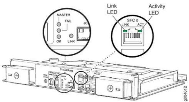
The LEDs located in the middle of the LCC-CB indicate its status. Table 39 on page 71 describes the functions of the LCC-CB LEDs.
Table 39: LCC-CB LEDs
| DescriptionStateColorLabel | |||
| LCC-CB is functioning as the master.On steadilyBlueMASTER | |||
| LCC-CB is functioning as the backup.Off- | |||
| LCC-CB has failed.On steadilyYellowFAIL | |||
| No faults have been detected on the LCC-CB.Off- | |||
| OK | Green | On steadily | LCC-CB is online and is functioning normally. |
| Blinking | LCC-CB is powering up, but not online. | ||
| Off- | LCC-CB is offline. |
The LEDs located next to each port indicate its status. Table 40 on page 71 describes the functions of the LCC-CB port LEDs.
Table 40: LCC-CB LEDs
| DescriptionStateColorLabel | |||
| ACT | Green | On steadily | Traffic is passing through the port. |
| Off- | No traffic is passing through the port. | ||
| SFCO LINK | Green | On steadily | 1-Gbps connection |
| On steadily | Yellow00-Mbps connection | ||
| Off- | LCC-CB is not connected to the TX Matrix Plus SFC.This port is not used.--JCS LINK |
Related Documentation
.T1600 Host Subsystem Description on page 41
•T1600 Control Boards Description on page 66
•T1600 Line-Card Chassis Control Board (LCC-CB) Description on page 69
•Maintaining the T1600 Host Subsystem on page 486
•Maintaining the T1600 Control Boards on page 477
•Troubleshooting the T1600 Control Boards on page 511
•Troubleshooting the T1600 Host Subsystems on page 510
CHAPTER 6
Line Card Components and Descriptions
• T1600 Flexible PIC Concentrator (FPC) Description on page 73
• T1600 FPCs Supported on page 84
• T1600 PIC Description on page 86
• T1600 PICs Supported on page 87
• T1600 End-of-Life PICs Supported on page 96
• T1600 PIC Combination Limitations on page 97
• T1600 PIC/FPC Compatibility on page 98
T1600 Flexible PIC Concentrator (FPC) Description
FPCs are hot-removable and hot-insertable.
• T1600 FPC Function on page 73
• T1600 FPC Slots on page 74
• T1600 FPC Components on page 74
• T1600 FPC Terminology on page 74
• Identifying the T1600 FPCs on page 75
T1600 FPC Function
FPCs house the PICs that connect the T1600 Core Router to network media. The main function of an FPC is to connect the PICs installed in it to the other T1600 router components. The Packet Forwarding Engine receives incoming packets from the PICs installed on the FPC and forwards them through the switch planes to the appropriate destination port. In a maximum configuration with eight Type 4 FPCs installed, the Packet Forwarding Engines can forward up to 1600 million packets per second (Mpps) for all packet sizes. The T1600 Core Router provides up to 800 gigabits per second (Gbps), full duplex switching (1600 Gbps of any-to-any, nonblocking, half-duplex switching).
When you install an FPC into a functioning router, the Routing Engine downloads the FPC software, the FPC runs its diagnostics, and the PICs housed on the FPC, are enabled. Forwarding on other FPCs continues uninterrupted during this process.
T1600 FPC Slots
Up to eight FPCs install vertically in the front of the router. The FPC slots are numbered FPC0 through FPC7, left to right. If a slot is not occupied by an FPC, an FPC blank panel must be installed to shield the empty slot and to allow cooling air to circulate properly through the router.
T1600 FPC Components
Each FPC consists of the following components:
- FPC card carrier.
- One or two Packet Forwarding Engines, consisting of Layer 2/Layer 3 Packet Processing ASICs, Switch Interface ASICs, T-series Internet Processor ASICs, and a Memory Mezzanine Board (MMB) which includes the Queuing and Memory Interface ASICs.
• Each Type 1 FPC has one Packet Forwarding Engine
• Each Type 2 FPC has one Packet Forwarding Engine
• Each Type 3 FPC has two Packet Forwarding Engines
• Each T640-FPC4-ES has one Packet Forwarding Engine
• Each T640-FPC4-1P-ES has one Packet Forwarding Engine
• Each T1600-FPC4-ES has two Packet Forwarding Engines - Processor Mezzanine Board (PMB), which includes a 300-MHz CPU, system controller, 256 MB of SDRAM, and two Fast Ethernet interfaces.
- Two LEDs, located on the craft interface above the FPC, that display the status of the FPC.
- FPC online/offline button, located on the craft interface above the FPC.
T1600 FPC Terminology
Regardless of whether you are holding an FPC vertically or horizontally, this document uses the same terms for all four edges of the FPC (see Figure 30 on page 75):
- Faceplate—Edge of the FPC that has slots into which you insert the PICs
- Connector edge—Edge opposite the faceplate; this edge has the connectors that attach to the midplane
- Top edge—Edge at the top of the FPC when it is vertical
- Bottom edge—Edge at the bottom of the FPC when it is vertical
Figure 30: FPC Edges

Identifying the T1600 FPCs
Check the label on the faceplate to identify the FPC. For FPCs without a label on the faceplate, check the location of a PIC's offline button and how the PIC is secured to the FPC. See Table 41 on page 75.
Table 41: Identifying the FPCs Supported by the T1600 Router
| Location of PIC Offline ButtonLabelontheFPCFaceplateFPC FPC | Methodof SecuringthePIC | ||
| E FPC1Enhanced FPC1 | of the PIC | Two captive screwsSlightly beneath the facep | |
| E-II FPC1Enhanced II FPC1 | of the PIC | Two captive screwsSlightly beneath the facep | |
| T640-FPC1-ESEnhanced Scaling FPC1 | of the PIC | Two captive screwsSlightly beneath the facep | |
| NoneFPC2 | the faceplate of each PIC | Two captive screwsInside an opening directly | |
| E FPC2Enhanced FPC2 | the faceplate of each PIC | Two captive screwsInside an opening directly | |
| E-II FPC2Enhanced II FPC2 | the faceplate of each PIC | Two captive screwsInside an opening directly | |
| Enhanced Scaling FPC2 | T640-FPC2-ES | the faceplate of each PIC | Two captive screwsInside an opening directly |
Table 41: Identifying the FPCs Supported by the T1600 Router (continued)
| Location of PIC Offline ButtonLabelontheFPCFaceplateFPC FPC | Methodof SecuringthePIC | ||
| NoneFPC3 | Inside an opening directly on Plastic ejector handle at the top of the PIC faceplate; captive screw at the bottom of the PIC faceplate | ||
| E FPC3Enhanced FPC3 | Inside an opening directly on Plastic ejector handle at the top of the PIC faceplate; captive screw at the bottom of the PIC faceplate | ||
| E-II FPC3Enhanced II FPC3 | Inside an opening directly on Plastic ejector handle at the top of the PIC faceplate; captive screw at the bottom of the PIC faceplate | ||
| T640-FPC3-ESEnhanced Scaling | The faceplate of each PIC on Two plastic ejector handles at the top and bottom of the PIC faceplate | ||
| FPC4T640 Enhanced Scaling | The faceplate of each PIC on Two plastic ejector handles at the top and bottom of the PIC faceplate | ||
| FPC4-IP | T640-FPC4-IP-EST640 Enhanced Scaling | The faceplate of each PIC on Two plastic ejector handles at the top and bottom of the PIC faceplate | |
| FPC4 | T1600-FPC4T1600 Enhanced Scaling | The faceplate of each PIC on Two plastic ejector handles at the top and bottom of the PIC faceplate | |
The T1600 router supports the Enhanced Scaling FPC1, as shown in Figure 31 on page 77.
Figure 31: Enhanced Scaling FPC1 Supported by the T1600 Router

The T1600 router supports the standard FPC2 and FPC3, as shown in Figure 32 on page 78
Figure 32: Standard FPC2 and FPC3 Supported by the T1600 Router

natural_image
Technical line drawings of two server racks labeled FPC2 and FPC3, showing internal components and wiring (no text or symbols beyond labels)The T1600 router supports the Enhanced II FPC1, FPC2, and FPC3, as shown in Figure 33 on page 79.
Figure 33: Enhanced II FPC1, FPC2, and FPC3 Supported by the T1600 Router
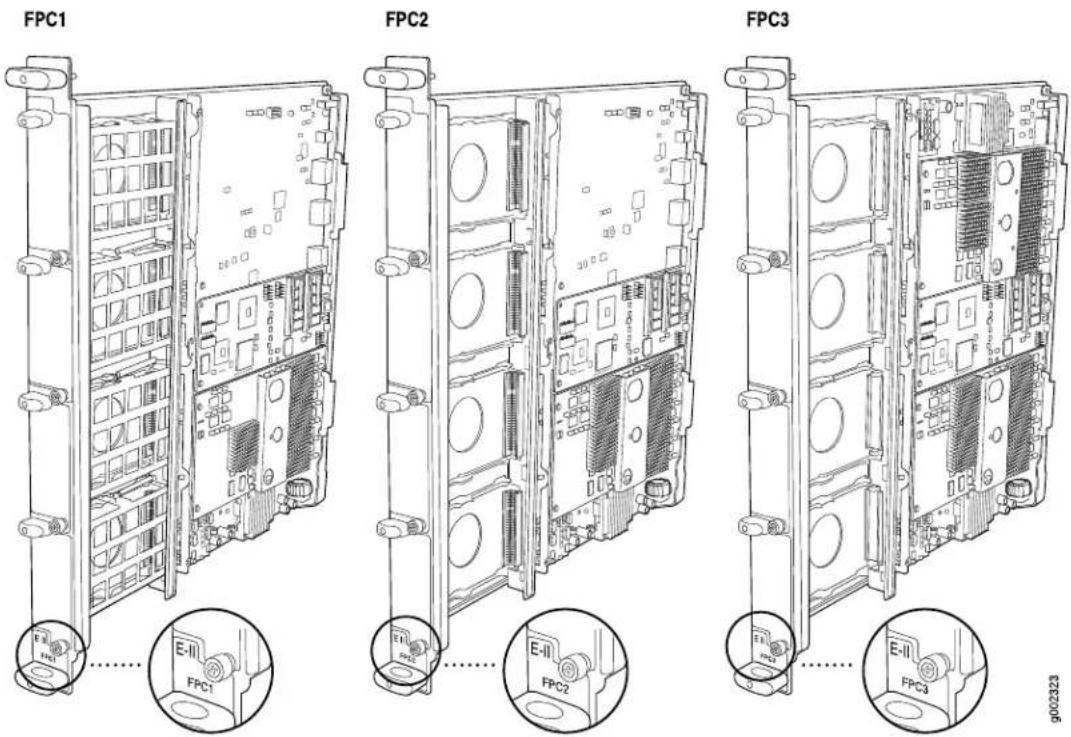
The T1600 router supports the Enhanced Scaling FPC2, as shown in Figure 34 on page 80.
Figure 34: T640 Enhanced Scaling FPC2 Supported by the T1600 Router

The T1600 router supports the Enhanced Scaling FPC3, as shown in Figure 35 on page 81.
Figure 35: T640 Enhanced Scaling FPC3 Supported by the T1600 Router

The T1600 router supports the T640 Enhanced Scaling FPC4, as shown in Figure 36 on page 82.
Figure 36: T640 Enhanced Scaling FPC4 Supported by the T1600 Router
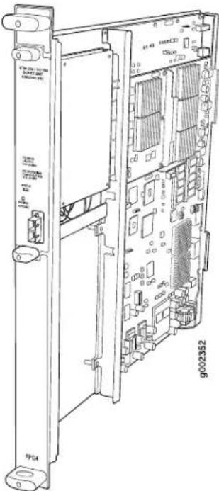
The T1600 router supports the T640 Enhanced Scaling FPC4-1P, as shown in Figure 37 on page 83.
Figure 37: T640 Enhanced Scaling FPC4-IP Supported by the T1600 Router

The T1600 router supports the T1600 Enhanced Scaling FPC4, as shown in Figure 38 on page 84.
Figure 38: T1600 Enhanced Scaling FPC4 Supported by the T1600 Router FPC4

Related Documentation
Packet Forwarding Engine Architecture for T Series Routers on page 8.
•T1600 FPCs Supported on page 84
•Maintaining T1600 FPCs on page 480
•Troubleshooting the T1600 FPCs on page 515
T1600 FPCs Supported
Table 42 on page 85 lists the FPCs for the T1600 Core Routers. You can install any combination of the FPCs currently supported. First Junos OS Release Supported indicates the first release that the FPC is supported in the T1600 router.

NOTE: End of life (EOL) indicates that the product has been removed from the price list and is no longer available for purchase. End of support (EOS) indicates that no new support contracts are available on these products and the last contract will expire on the EOS date associated with each product. For more information about EOS or EOL products, see the product support notification (PSN) hardware end-of-life announcements.
http://www.juniper.net/techpubs/hardware/eol.html
Table 42: FPCs Supported by the T1600 Router
| FPC Model NumberFPC | Maximum RBCbTypef PICs | Maximum Throughput per FPC | First Junos OS Release Supported | ||
| 1 | 4 Gbps4T640-FPC1-5EEndalone: FPC1 | ||||
| EOL details: PSN-2007-12-035 | Routing matrix: 10.0 | ||||
| 4 Gbps4T640-FPC1-5EEndalone: 8I5FPC1 | |||||
| EOL details: PSN-2010-08-920 | Routing matrix: 10.0 | ||||
| FPC1 | 4 Gbps4T640-FPC1-5EEndalone: 9Scaling Routing matrix: 10.0 | ||||
| 2 | 16 Gbps4T640-FPC2-5E6Dalone: 8.5 | ||||
| EOS details: PSN-2004-05-010 | Routing matrix: 10.0 | ||||
| Enhanced 16 Gbps4T640-FPC2-5E6Dalone: 8.5 | |||||
| EOL details: PSN-2007-12-035 | Routing matrix: 10.0 | ||||
| Enhanced 16 Gbps4T640-FPC2-5E6Dalone: 8.5 | |||||
| EOL details: PSN-2010-08-920 | Routing matrix: 10.0 | ||||
| FPC2 | Enhanced 15 Gbps4T640-FPC2-5E6Dalone: 9.5 | ||||
| Routing matrix: 10.0 | |||||
Table 42: FPCs Supported by the T1600 Router (continued)
| FPC Model NumberFPC Name | Maximum FBCbTypef PICs | Maximum Throughput per FPC | First Junos OS Release Supported | ||
| 3 | 8.540 Gbps4T640-FPC3FPC3 | ||||
| EOS details: PSN-2004-05-010 | |||||
| 8.540 Gbps4T640-FPC3-EEnhanced | |||||
| EOL details: PSN-2007-12-035 | |||||
| 8.540 Gbps4T640-FPC3-E2Enhanced | |||||
| EOL details: PSN-2010-08-920 | |||||
| 9.040 Gbps4T640-FPC3-ESEnhanced | |||||
| FPC3 | |||||
| 4 | T640 En550 Gbps1T640-FPC4-ES | ||||
| Scaling FPC4 | |||||
| EOL details: PSN-2010-07-878 | |||||
| FPC4-IP | Enhanced 50 Gbps1T640-FPC4-ES | Routing matrix: 10.0 | |||
| Scaling FPC4 | T1600 Enhanced | T1600-FPC4-ES | 2 | 8.5100 Gbps | |
| Related Documentation | Packet Forwarding Engine Architecture for T Series Routers on page 8 | ||||
| T1600 Flexible PIC Concentrator (FPC) Description on page 73 | |||||
| Maintaining T1600 FPCs on page 480 | |||||
| Troubleshooting the T1600 FPCs on page 515 | |||||
T1600 PIC Description
PICs provide the physical connection to various network media types, receiving incoming packets from the network and transmitting outgoing packets to the network. During this process, each PIC performs framing and line-speed signaling for its media type. Before transmitting outgoing data packets, the PICs encapsulate the packets received from the FPCs. Each PIC is equipped with an ASIC that performs control functions specific to the media type of that PIC.
PICs are hot-removable and hot-insertable. You can install up to four PICs in each Type 1, 2, and 3 FPC, one PIC in each T640 Enhanced Scaling FPC4 or Enhanced Scaling FPC4-IP, and one or two PICs in each T640 Enhanced Scaling FPC4. Type 1 and Type 2 PICs have captive screws at their upper and lower corners. Type 3 PICs have an upper ejector handle and a lower captive screw. Type 4 PICs have an upper ejector handle and a lower ejector handle.
The router supports various PICs, including ATM, Channelized, Gigabit Ethernet, IP Services, and SONET/SDH interfaces. Blank PICs resemble other PICs but do not provide any physical connection or activity. When a slot is not occupied by a PIC, you must insert a blank PIC to fill the empty slot and ensure proper cooling of the system.
Related Documentation
T1600 PIC Combination Limitations on page 97.
- Packet Forwarding Engine Architecture for T Series Routers on page 8
- Maintaining T1600 PICs and PIC Cables on page 488
•Troubleshooting the T1600 PICs on page 519
T1600 PICs Supported
Table 43 on page 88 through Table 56 on page 95 list the PICs supported by the T1600 router by PIC family.
• ATM2 IQ PICs on page 87
• Channelized PICs on page 88
• DS3 and E3 PICs on page 89
• Fast Ethernet PICs on page 90
• Gigabit Ethernet PICs on page 90
• 10-Gigabit Ethernet PICs on page 93
• 40-Gigabit Ethernet PICs on page 94
• 100-Gigabit Ethernet PICs on page 94
• Services PICs on page 94
• SONET/SDH PICs on page 95
ATM2 IQ PICs
Table 43 on page 88 lists the ATM2 IQ PICs supported by the T1600 router.
Table 43: ATM2 IQ PICs Supported by the T1600 Router
| First Junos OS Release SupportConnect | ||||
| Router) | PB-2E3-ATM24ATM2 E3 IQ PIC (T1600 | 8.5Coaxial: | ||
| • 10 ft (3.05 m) posilock SMB to BNC cable (provided) | ||||
| • Four pairs of Rx and Tx coaxial cables | ||||
| (T1600 Router) | 2ATM2 OC3/STM1 IQ PIC PB-2OC3-ATM2-SMIR | • Optical: SC/PCPB-2OC3-ATM2-MM | ||
| ATM2 OC12/STM4 IQ PICs (T1600 Router) | ||||
| • ATM2 OC12/STM4 IQ PIC 2 | PB-2OC12-ATM2-SMIR | • Optical: SC/PCPB-2OC12-ATM2-MM | ||
| • ATM2 OC12/STM4 IQ PIC 1 | PB-1OC12-ATM2-SMIR | • Optical: SC/PCPB-1OC12-ATM2-MM | ||
| ATM2 OC48/STM16 IQ PIC with SFP (T1600 Router) | 1 | PB-1OC48-ATM2-SFP | • Optical: LC/PC | 8.5 |
Channelized PICs
- Table 44 on page 88 lists the channelized IQ PICs supported by T1600 router.
- Table 45 on page 89 lists the enhanced channelized IQ (IQE) PICs supported by T1600 router.
Table 44: Channelized IQ PICs Supported by the T1600 Router
| First Junos OS Release SupportConnect | ||||
| (T1600 Router) | 4Channel/PS3DS3-PP | 8.5Coaxial | ||
| Standard DS3 BNC coaxial cable interfaces | ||||
| (T1600 Router) | Optical: SC/PC | 8.5 | ||
| Channelized STM1 IQ PIC (T1600 Router) | 1 | PB-1CHSTM1-SMIR-QPP | Optical: SC/PC | |
Table 45: Channelized Enhanced IQ (IQE) PICs Supported by the T1600 Router
| First Junos OS Release SupportConnect | ||||
| IQ (IQE) PIC (T1600 Router) | PB-4CHDS3-E3-IQE-BNC4Channelized DS3/E3 Enhanced Standard DS3 BNC coaxial cable interfaces | 9.3Coaxial | ||
| IQ (IQE) PIC (T1600 Router) | PB-1OCHE1-T1-IQE-RJ4810Channelized E1/T1 Enhanced 120-onm RJ-48C connector (female) | 9.5 | ||
| Channelized OC3/STM1 2Enhanced IQ (IQE) PIC with SFP (T1600 Router) | PB-2CHOC3-STM1-IQE-SFP | Optical: LC/PC | 9.3 | |
| Channelized OC12/STM4 Enhanced IQ (IQE) PICs with SFP (T1600 Router) | ||||
| Channelized OC12/STM4 1Enhanced IQ (IQE) PIC with SFP | PB-1CHOC12-STM4-IQE-SFP | Optical: LC/PC | 9.3 | |
| Channelized OC12/STM4 4Enhanced IQ (IQE) PIC with SFP (Type 2) | PB-4CHOC12-STM4-IQE-SFP | Optical: LC/PC | 9.4 | |
| Channelized OC12/STM4 4Enhanced IQ (IQE) PIC with SFP (Type 3) | PC-4CHOC12STM4-IQE-SFP | Optical: LC/PC | 10.1 | |
| Channelized OC48/STM16 1Enhanced IQ (IQE) PIC with SFP (T1600 Router) | PB-1CHOC48-STM16-IQE-SFP | Optical: LC/PC | 9.4 | |
DS3 and E3 PICs
Table 46 on page 89 lists the DS3 and E3 PICs supported by T1600 router.
Table 46: DS3 and E3 PICs Supported by the T1600 Router
| First Junos OS Release SupportConnect | ||||
| (T1600 Router) | 4DS3/E3 PBHD/DS3/EQ/QE/BNPIC | Coaxial | 9.3R2 | |
| • Standard DS3 BNC coaxial cable interfaces | ||||
| 4E3 IQ PB-(E5/QF/Router) | 8.5Coaxial | |||
| • Standard DS3 BNC coaxial cable interfaces | ||||
Fast Ethernet PICs
Table 47 on page 90 lists the Fast Ethernet PICs supported by T1600 router.
Table 47: Fast Ethernet PICs Supported by the T1600 Router
| First Junos OS Release SupportConnect | ||||
| Router) | PB-4FE-TX4Fast Ethernet PIC (T168045 | 8.5 | ||
| • Two-pair, Category 5 unshielded twisted-pair • Pinout: MDI noncrossover | ||||
Gigabit Ethernet PICs
• Table 48 on page 90 lists the Gigabit Ethernet PICs supported by T1600 router.
• Table 49 on page 91 lists the Gigabit Ethernet IQ PICs supported by T1600 router.
• Table 50 on page 92 lists the Gigabit Ethernet IQ2 PICs supported by T1600 router.
- Table 51 on page 92 lists the Gigabit Ethernet Enhanced IQ2 PICs supported by T1600 router.
Table 48: Gigabit Ethernet PICs Supported by the T1600 Router
| First Junos OS Release SupportConnect |
Gigabit Ethernet PICs with SFP (T1600 Router)
| Gigabit Ethernet PIC with SFP | PB-1GE-SFP1 | Optical: LC Copper: RJ-45 Four-pair, Category 5 shielded twisted-pair connectivity Pinout: MDI crossover | 8.5 |
| Gigabit Ethernet PIC with SFP | PB-2GE-SFP2 | Optical: LC Copper: RJ-45 Four-pair, Category 5 shielded twisted-pair connectivity Pinout: MDI crossover | 8.5 |
Table 48: Gigabit Ethernet PICs Supported by the T1600 Router (continued)
| First Junos OS Release SupportConnect | ||||
| • Gigabit Ethernet PIC with SFP | PB-4GE-SFP4 | • Optical: LC• Copper: RJ-45• Four-pair, Category 5 shielded twisted-pair connectivity• Pinout: MDI crossover | 8.5 | |
| • Gigabit Ethernet PIC with SFP | PC-10GE-SFP10 | • Optical: LC• Copper: RJ-45• Four-pair, Category 5 shielded twisted-pair connectivity• Pinout: MDI crossover | 8.5 |
Table 49: Gigabit Ethernet IQ
| First Junos OS Release SupportConnect | ||||
| Gigabit Ethernet IQ PICs with SFP (T1600 Router) | ||||
| • Gigabit Ethernet IQ PIC with SFP | PB-1GE-SFP-QPP1 | • Optical: LC• Copper: RJ-45• Four-pair, Category 5 shielded twisted-pair connectivity• Pinout: MDI crossover | 8.5 | |
| • Gigabit Ethernet IQ PIC with SFP | PB-2GE-SFP-QPP2 | • Optical: LC• Copper: RJ-45• Four-pair, Category 5 shielded twisted-pair connectivity• Pinout: MDI crossover | 8.5 | |
Table 50: Gigabit Ethernet IQ2
| First Junos OS Release SupportConnect |
Gigabit Ethernet IQ2 PICs with SFP (T1600 Router)
| PIC with SFP | Optical: LCType 1 Gigabit 8.5Copper: RJ-45Four-pair, Category 5shielded twisted-pairconnectivityPinout: MDI crossover | ||
| Type 2 Gigabit Ethernet IQ2 PIC with SFP | PB-8GE-TYPE2-SFP-IQ28 | Optical: LC Copper: RJ-45Four-pair, Category 5shielded twisted-pairconnectivityPinout: MDI crossover | 8.5 |
| Type 3 Gigabit Ethernet IQ2 PIC with SFP | PB-8GE-TYPE3-SFP-IQ28 | Optical: LC Copper: RJ-45Four-pair, Category 5shielded twisted-pairconnectivityPinout: MDI crossover | 8.5 |
Table 51: Gigabit Ethernet IQ2E PICs
| First Junos OS Release SupportConnect |
Gigabit Ethernet Enhanced IQ2 (IQ2E) PICs with SFP (T1600 Router)
| Type 1 Gigabit Ethernet Enhanced IQ2 (IQ2E) PIC with SFP | 4 | PB-4GE-TYPE1-SFP-IQ2E | Optical: LC | 9.4 |
| Copper: RJ-45 | ||||
| Four-pair, Category 5 shielded twisted-pair connectivity | ||||
| Pinout: MDI crossover | ||||
| First Junos OS Release SupportConnect | ||||
| • Type 2 Gigabit Ethernet Enhanced IQ2 (IQ2E) PIC with SFP | PB-8GE-TYPE2-SFP-IQ28 | • Optical: LC• Copper: RJ-45• Four-pair, Category 5 shielded twisted-pair connectivity• Pinout: MDI crossover | 9.4 | |
| • Type 3 Gigabit Ethernet Enhanced IQ2 (IQ2E) PIC with SFP | PB-8GE-TYPE3-SFP-IQ28 | • Optical: LC• Copper: RJ-45• Four-pair, Category 5 shielded twisted-pair connectivity• Pinout: MDI crossover | 9.4 |
10-Gigabit Ethernet PICs
Table 52 on page 93 lists the 10-Gigabit Ethernet PICs supported by T1600 router.
Table 52: 10-Gigabit Ethernet PICs Supported by the T1600 Router
| First Junos OS Release SupportConnect | |||||
| with XFP (T1600 Router) | Optical: LCPC-1XGE-TYPE3-XFP-IQ2110-Gigabit Ethernet IQ2 F | ||||
| IQ2 (IQ2E) PIC with XFP (T1600 Router) | Optical: LCPC-1XGE-TYPE3-XFP-IQ2E110-Gigabit Ethernet Enha | ||||
| XENPAK (T1600 Router) | 1XENPAKPC1XGE-EXNCA with 8.5 | ||||
| 10-Gigabit Ethernet DWDM PIC (T1600 Router) | 1 | PC-1XGE-DWDM-CBAND | Optical: SC | 8.5 | |
| 10-Gigabit Ethernet DWDM OTN PIC (T1600 Router) | 1 | PC-1XGE-DWDM-OTN | Optical: SC | 9.4 | |
| 10-Gigabit Ethernet LAN/WAN PIC with Oversubscription and SFP+ (T1600 Router) | 10 | PD-5-10XGE-SFPP | Optical: LC | 10.1 | |
| 10-Gigabit Ethernet LAN/WAN PIC with XFP (T1600 Router) | 4 | PD-4XGE-XFP | Optical: LC | 9.0 | |
40-Gigabit Ethernet PICs
Table 53 on page 94 lists the 40-Gigabit Ethernet PICs supported by T1600 router.
Table 53: 40-Gigabit Ethernet PICs Supported by the T1600 Router
| First Junos OS Release SupportConnect | ||||
| 40-Gigabit Ethernet | ||||
| CFP (T1600 Router) | 11.4Optical: SCPD-1XLE-CFP440-Gig | |||
100-Gigabit Ethernet PICs
Table 54 on page 94 lists the 100-Gigabit Ethernet PICs supported by T1600 router.
Table 54: 100-Gigabit Ethernet PICs Supported by the T1600 Router
| First Junos OS Release SupportConnect | ||||
| CFP (T1600 Router) | 1100-Gigabit Ethernet PIC with FPC) | • Optical: SC | 10.3PD-1CE-CFP-FPC4 (PIC and | |
| NOTE: This PIC is only available packaged in an assembly with the T1600-FPC4-ES FPC. | ||||
Services PICs
Table 55 on page 94 lists the Services PICs supported by T1600 router.
Table 55: Services PICs Supported by the T1600 Router
| First Junos OS Release SupportConnect | ||||
| Services | ||||
| MultiServices PICs (T1600 Router) | ||||
| • MultiServices 100 PIC | 0 | PB-MS-100-1 | • None | 8.5 |
| • MultiServices400 PIC | 0 | PB-MS-400-2 | • None | 8.5 |
| • MultiServices 500 PIC | 0 | PB-MS-500-3 | • None | 8.5 |
| Tunnel Services PIC (T1600 Router) | ||||
| • Type 1 Tunnel Services PICO | PB-TUNNEL-1 | • None | 8.5 | |
| • Type 2 Tunnel Services PIC | • NonePB-TUNNELO | 8.5 | ||
| • Type 3 Tunnel Services PIC | • NonePC-TUNNELO | 8.5 | ||
| (T1600 Router) | • NonePD-TUNNEL040-Gigabit | 8.5 Tunnel Services PIC | ||
SONET/SDH PICs
Table 56: SONET/SDH PICs Supported by the T1600 Router
| First Junos OS Release SupportConnect | ||||
| SONET/SDH OC3/STM1 Enhanced IQ (IQE) PIC with SFP (T1600 Router) | 4 | PB-4OC3-STM1-IQE-SFP | Optical: LC | 9.3R2 |
| SONET/SDH OC3/STM1 (Multi-Rate) PICs with SFP (T1600 Router) | ||||
| Type 1 SONET/SDH OC3/STM1 (Multi-Rate) PIC with SFP | 4 | PB-4OC3-1OC12-SON-SFP | Optical: LC | 8.5 |
| Type 2 SONET/SDH OC3/STM1 (Multi-Rate) PIC with SFP | PB-4OC3-1OC12-SON2-SFP4 | Optical: LC | 8.5 | |
| SONET/SDH OC12/STM4 Enhanced IQ (IQE) PIC with SFP (T1600 Router) | 1 | PB-1OC12-STM4-IQE-SFP | Optical: LC | 9.3 |
| SONET/SDH OC12/STM4 (Multi-Rate) PICs with SFP (T1600 Router) | ||||
| SONET/SDH OC12/STM4 (Multi-Rate) PIC with SFP (T1600 Router) | 1 | PB-1OC12-SON-SFP | Optical: LC | 8.5 |
| SONET/SDH OC12/STM4 (Multi-Rate) PIC with SFP (T1600 Router) | 4 | PB-4OC3-4OC12-SON-SFP | Optical: LC | 8.5 |
| SONET/SDH OC48c/STM16 PIC with SFP (T1600 Router) | 4 | PC-4OC48-SON-SFP | Optical: LC | 8.5 |
| SONET/SDH OC48/STM16 Enhanced IQ (IQE) PIC with SFP (T1600 Router) | 4 | PC-4OC48-STM16-IQE-SFP | Optical: LC | 10.4R2 |
Table 56: SONET/SDH PICs Supported by the T1600 Router (continued)
| First Junos OS Release SupportConnect | ||||
| (Multi-Rate) PIC with SFP (T1600 Router) | Optical: LCPB-1OC48-SON-B-SFP1SONET/SDH OC48/STM16 | |||
| PIC (T1600 Router) | Optical: LCPC-1OC192-SON-B/SR1SONET/SDH OC192c/STM64 | |||
| PICs with XFP (T1600 Router) | Optical: LCPC-1OC192-SON-B/SP1SONET/SDH OC192/STM64 | |||
| PICs with XFP (T1600 Router) | Optical: SDH/SPB-400792/STON85FP4 | |||
| SONET/SDHOC768c/STM256 1 PIC (T1600 Router) | PD-1OC768-SON-SR | Optical: SC 8.5 | ||
Related Documentation
T1600 PIC Description on page 86
• T1600 PIC Combination Limitations on page 97
• T1600 FPCs Supported on page 84
T1600 End-of-Life PICs Supported
Table 57 on page 96 lists the end-of-life PICs supported by the T1600 router. The PICs are listed alphabetically by PIC family.
Table 57: End-of-Life PICs Supported in the T1600 Router
| PIC Family and Type | Ports | Model Number | Connector |
| Channelized IQ | |||
| Channelized OC12 IQ EOL PIC (T1600 Router) | 1 | PE-1CHOC12SMIR-QPP | • Optical: SC/PC |
| DS3/E3 | |||
| DS3 EOL PIC (T1600 Router) | 4 | PB-2DS3 | • Custom 10 ft (3.05 m) posilock SMB to BNC male cable, separ Rx and Tx (provided) |
| Services | |||
| Adaptive Services II EOL PIC (T1600 Router) | 0 | PB-AS2 | • None |
| Adaptive Services II Layer 2 Services EOL PIC (T1600 Router) | 0 | PB-AS2-LAYER2SERVICES | • None |
| OLink Services EOL PIC (T1600 Router)PB-LS-32PB-LS-128 | NonePB-LS-4 | ||
| NonePB-PM20Monitoring Services | |||
| NonePB-PM30Monitoring Services | |||
| SONET/SDH | |||
| 4SONET/SDH OC3c/STM1 EOL PICs (T1600 PB-4OC3-SON-SMIR | Optical: SC/PCPB-4OC3-SON-MM | ||
| SONET/SDH OC12c/STM4 EOL PICs (T1600 Router) | |||
| • SONET/SDH OC12c/STM4 PIC | Optical: SC/PCPB-1OC12-SON-MM | ||
| • SONET/SDH OC12c/STM4 PIC | 4PB-4OC12-SON-SMIR | Optical: SC/PCPB-4OC12-SON-M | |
| SONET/SDH OC48c/STM16 EOL PIC with SFP (T1600 Router) | 1 | PB-1OC48-SON-SFP | Optical: LC/PC |
Related Documentation
T1600 PIC Description on page 86
T1600 PIC Combination Limitations
In most cases, you can install PICs of different media types on the same FPC as long as the FPC and the router support those PICs. However, configuration rules might limit certain combinations of PICs on some platforms.
Newer Junos OS services for some PICs can require significant Internet Processor ASIC memory. Ethernet and SONET PICs typically do not use large amounts of memory. Gigabit Ethernet, ATM2, IQ serial PICs, and Multiservices PICs use more. To conserve memory, you can group PICs in the same family together on the same FPC.
If you have different PIC families on a single FPC, review the configuration rules to plan which PICs to install on the FPCs for your router. Consult technical bulletin PSN-2007-01-023 for information about configuration rules for PIC combinations on the Juniper Networks Support site at https://www.juniper.net/alerts/.
When you upgrade to Junos OS Release 7.5 or later, a warning appears if any configuration rules affect your PIC combinations. If you continue the installation, one or more PICs might appear to be online (the LEDs are on), but the Junos OS cannot enable them and they cannot pass traffic. As a workaround, you can:
• Install a Junos OS release that supports the combination.
• Install PICs on a different FPC.
- Remove PICs from the affected FPC.
Related Documentation
T1600 PIC Description on page 86.
•T1600 PICs Supported on page 87
•T1600 FPCs Supported on page 84
•T1600 PIC/FPC Compatibility on page 98
T1600 PIC/FPC Compatibility
The PIC/FPC compatibility matrixes list the current PICs for the T1600 router. For example, Junos OS Release 8.5 is the first release in which the T640-FPC1-E2 supports the ATM2 OC3/STM1 IQ, 2-port PIC.

NOTE: A – indicates that the FPC does not support the PIC.
- PIC/FPC Compatibility (Type 1 FPCs and Type 1 PICs) on page 98
- PIC/FPC Compatibility (Type 2 FPCs and Type 2 PICs) on page 100
- PIC/FPC Compatibility (Type 3 FPCs and Type 3 PICs) on page 101
- PIC/FPC Compatibility (Type 4 FPCs and Type 4 PICs) on page 103
PIC/FPC Compatibility (Type 1 FPCs and Type 1 PICs)
Table 58 on page 98 provides a PIC/FPC compatibility matrix for the current Type 1 PICs for the T1600 router and Type 1 FPCs.

NOTE: A T1600 router in a routing matrix supports Type 1 PICs in Junos OS Release 10.0 and later.
Table 58: T1600 PIC/FPC Compatibility Type 1
| T640-FPC1-EST6 | ||||
| ATM2 IQ PICs | ||||
| ATM2 E3 IQ, 4-port | PB-4E3-ATM2 | 8.5 | -8.5 | |
| ATM2 OC3/STM1 IQ, 2-port | PB-2OC3-ATM2-MM | 8.5 | -8.5 | |
| PB-2OC3-ATM2-SMIR | ||||
Table 58: T1600 PIC/FPC Compatibility Type 1 (continued)
| T640-FPC1-EST6 | ||||
| ATM2 OC12/ STM4 IQ, 1-port | PB-1OC12-ATM2-SMIR | -8.58.5PB-1OC12-ATM2-MM | ||
| Channelized IQ PICs | 9.48.58.5PB-4CHDS3-QPPChDS3 IQ | |||
| 9.48.58.5PB-1CHOC3-SMIR-QPPChO | ||||
| 9.48.58.5PB-1CHSTM1-SMIR-QPPChS | ||||
| Channelized IQE PICs | ||||
| ChDS3/E3 IQE, 4-port | PB-4CHDS3-E3-IQE-BNC | 9.3 | 9.3 | 9.4 |
| ChEI/TI IQE, 10-port | PB-1OCHE1-TI-IQE-RJ48 | 9.5 | 9.5 | 9.5 |
| ChOC3/STM1 IQE, 2-port | PB-2CHOC3-STM1-IQE-SFP | 9.3 | 9.3 | 9.4 |
| ChOC12/STM4 IQE, 1-port | PB-1CHOC12-STM4-IQE-SFP | 9.3 | 9.3 | 9.4 |
| DS3 and E3 PICs | ||||
| DS3/E3 IQE, 4-port | PB-4DS3-E3-IQE-BNC | 9.3R2 | 9.3R2 | 9.4 |
| E3 IQ, 4-port | -8.58.5PB-4E3-QPP | |||
| Fast Ethernet and Gigabit Ethernet PICs | ||||
| Fast Ethernet, 4-port | 9.48.58.5PB-4FE-TX | |||
| Gigabit Ethernet, 1-port SFP | PB-1GE-SFP | 8.5 | 8.5 | 9.4 |
| Gigabit Ethernet IQ PICs | ||||
| SFP | -8.58.5PB-1GE-SFP-QPPGigabit Ethe | |||
| Gigabit Ethernet IQ2 PICs | ||||
| Gigabit Ethernet IQ2, 4-port SFP | PB-4GE-TYPE1-SFP-IQ2 | 8.5 | 8.5 | 9.4 |
| Gigabit Ethernet IQ2E PICs | ||||
| Gigabit Ethernet IQ2E, 4-port SFP | PB-4GE-TYPE1-SFP-IQ2E | 9.4 | 9.4 | - |
| Services PICs | ||||
| MultiServices 100 | 9.48.58.5PB-MS-100-1 | |||
| 9.48.58.5PB-TUNNEL1Tunnel Service | ||||
| SONET/SDH PICs | ||||
| OC3/STM1 IQE, 4-port SFP | PB-4OC3-STM1-IQE-SFP | 9.3R2 | 9.3R2 | - |
| 4-port (Type 1) | OC3c/STM1 (Multi-Rate) | 9.58.5PB-4OC3-1OC12-SON-SFP | ||
| OC12/STM4 IQE, 1-port SFP | PB-1OC12-STM4-IQE-SFP | 9.3 | 9.3 | - |
| 1-port (Type 1) | 9.48.58.5PB-1OC12-SON-SFPOC12c/S | |||
PIC/FPC Compatibility (Type 2 FPCs and Type 2 PICs)
Table 59 on page 100 provides a PIC/FPC compatibility matrix for the current Type 2 PICs for the T1600 router and Type 2 FPCs.

NOTE: A T1600 router in a routing matrix supports Type 2 PICs in Junos OS Release 10.0 and later.
Table 59: T1600 PIC/FPC Compatibility Type 2
| PIC | PIC Model Number | T640-FPC2 | T640-FPC2-E | T640-FPC2-B2 | T640-FPC2-ES |
| ATM2 IQ PICs | |||||
| ATM2 OC12/ STM4 IQ, 1-port | PB-1OC12-ATM2-MM | 8.5 | 8.5 | 8.5 | - |
| PB-1OC12-ATM2-SMIR | |||||
| ATM2 OC48/ STM16 IQ, 1-port SFP | PB-1OC48-ATM2-SFP | 8.5 | 8.5 | 8.5 | - |
| Channelized IQE PICs | |||||
| ChOC12/STM4 IQE, 4-port | PB-4CHOC12-STM4-IQE-SFP | - | 9.4 | 9.4 | 9.5 |
| ChOC48/STM16 IQE, 1-port | PB-1CHOC48-STM16-IQE-SFP | - | 9.4 | 9.4 | 9.5 |
| Gigabit Ethernet PICs | |||||
| Gigabit Ethernet, 2-port SFP | PB-2GE-SFP | 8.5 | 8.5 | 8.5 | 9.5 |
| Gigabit Ethernet, 4-port SFP | PB-4GE-SFP | 8.5 | 8.5 | 8.5 | 9.5 |
| Gigabit Ethernet IQ PICs | |||||
Table 59: T1600 PIC/FPC Compatibility Type 2 (continued)
| PIC | PIC Model Number | T640-FPC2 | T640-FPC2-E | T640-FPC2-E2 | T640-FPC2-ES |
| SFP | -8.58.58.5PB-2GE-SFP-QPPGiga | ||||
| Gigabit Ethernet IQ2 PICs | |||||
| Gigabit Ethernet IQ2,8-port SFP (Type 2) | PB-8GE-TYPE2-SFP-IQ2 | - | 8.5 | 8.5 | 9.5 |
| Gigabit Ethernet IQ2E PICs | |||||
| 8-port SFP (Type 2) | Gigabit Ethernet IQ2E,49.4-PB-8GE-TYPE2-SFP-IQ2 | ||||
| Services PICs | |||||
| MultiServices 4009.58.58.5-PB-MS-400-2 | |||||
| Tunnel Services 9.58.58.58.5PB-TUNNEL | |||||
| SONET/SDH PICs | |||||
| 4-port (Type 2) | OC3c/STM1 (Multi-Ra5)8.5-PB-4OC3-1OC12-SON2-9 | ||||
| 4-port (Type 2) | OC12c/STM4 (Multi-Ra5)5-PB-4OC3-4OC12-SON- | ||||
| OC48c/STM16, 1-pa85.58.5PB-1OC48-SON-SFP | |||||
| 4-port (Type 2) | OC48/STM16 (Multi-Ra5)5-PB-1OC48-SON-B-SFP | ||||
PIC/FPC Compatibility (Type 3 FPCs and Type 3 PICs)
Table 60 on page 101 provides a PIC/FPC compatibility matrix for the current Type 3 PICs for the T1600 router and Type 3 FPCs.

NOTE: A T1600 router in a routing matrix supports Type 3 PICs in Junos OS Release 9.6R2 and later.
Table 60: T1600 PIC/FPC Compatibility Type 3
| Type 3 PIC | PIC Model Number | T640-FPC3 | T640-FPC3-E | T640-FPC3-E2 | T640-FPC3-ES |
| Channelized IQE | PICs | ||||
| ChOC12/STM4 IQE, 4-port | PC-4CHOC12-STM4-IQE-SFP | - | - | - | 10.1 |
| Gigabit Ethernet | PICs |
Table 60: T1600 PIC/FPC Compatibility Type 3 (continued)
| T640-FPC3-EST6 | |||||
| 10-port SFP | 9.08.58.58.5PC-10-GE-SFPGigabit Eth | ||||
| Gigabit Ethernet IQ2 PICs | |||||
| IQ2, 8-port SFP(Type 3) | 9.08.58.58.5PC-8GE-TYPE3-SFP-IQ2C | ||||
| Ethernet IQ2,1-port XFP | 10-Gigabit Ethernet 10-GE-58.58.5PC-1XGE-TYPE3-XFP-IQ2 | ||||
| Gigabit Ethernet and 10-Gigabit Ethernet IQ2E PICs | |||||
| Gigabit Ethernet IQ2E, 8-port SFP(Type 3) | PC-8GE-TYPE3-SFP-IQ2E | 9.4 | 9.4 | 9.4 | 9.4 |
| 10-Gigabit Ethernet IQ2E,1-port XFP | PC-1XGE-TYPE3-XFP-IQ2E | 9.4 | 9.4 | 9.4 | 9.4 |
| 10-Gigabit Ethernet PICs | |||||
| 10-Gigabit Ethernet,1-port XENPAK | 10GBase-ER and10GBASE-LR transceivers installed | 9.08.58.58.5PC-1XGE-XENPAK with | |||
| 10GBASE-SR and10GBASE-ZR transceivers installed | 9.08.58.58.5PC-1XGE-XENPAK with | ||||
| Ethernet,1-port DWDM | 9.08.58.58.5PC-1XGE-DWDM-CBAND1 | ||||
| 10-Gigabit Ethernet,1-port DWDM OTN | PC-1XGE-DWDM-OTN | 9.4 | 9.4 | 9.4 | 9.4 |
| Services PICs | |||||
| MultiServices 500 | PC-MS-500-3 | - | 8.5 | 8.5 | 9.3 |
| Tunnel Service 58.58.5PC-TUNNEL | |||||
SONET/SDH PICs
Table 60: T1600 PIC/FPC Compatibility Type 3 (continued)
| T640-FPC3-EST6 | |||||
| OC48/STM16 IQE, 4-port SFP | in a standalone T1600 routerThis PIC is not supported in a T1600 router connected to a TX Matrix Plus router. | 10.4R2----PC-4OC48-STM16-IQE-SFP | |||
| OC48c/STM16, 4-port SFP | PC-4OC48-SON-SFP | 8.5 | 8.5 | 8.5 | 9.0 |
| OC192c/STM64, 1-port | PC-1OC192-SON-VSR | 8.5 | 8.5 | 8.5 | 9.0 |
| OC192/STM64, 1-port XFP | PC-1OC192-SON-XFP | - | 8.5 | 8.5 | 9.0 |
PIC/FPC Compatibility (Type 4 FPCs and Type 4 PICs)
Table 61 on page 103 provides a PIC/FPC compatibility matrix for the current Type 4 PICs for the T1600 router and Type 4 FPCs.

NOTE: A TI600 router in a routing matrix supports Type 4 PICs in Junos OS Release 9.6R2 and later.
Table 61: T1600 PIC/FPC Compatibility Type 4
| Type 4 PIC | PIC Model Number | T640-FPC4-ES | T1600-FPC4-ES | T640-FPC4-IP-ES |
| 10-Gigabit Ethernet PICs | ||||
| 10-Gigabit Ethernet, 4-port LAN/WAN XFP | PD-4XGE-XFP | 9.0 | 9.0 | 9.5 |
Table 61: T1600 PIC/FPC Compatibility Type 4 (continued)
| T640-FPC4-1P-EST | |||
| LAN/WAN with Oversubscription and SFP+ | 10.1PD-5-10XGE-SFPP10-Gigabit | 10.110.1 | |
| NOTE: To support PD-5-10XGE-SFPP, the hardware version of the T1600-FPC4-ES (part number 710-013037) REV 13or later is required. | |||
40-Gigabit Ethernet PICs
11.411.4-PD-1XLE-CFP40-Gigabit with
| 100-Gigabit Ethernet PICs | ||||
| 100-Gigabit with CFP | PD-ICE-CFP-FPC4 (PIC and FPC) | - | - | 10.3 |
| NOTE: This PIC is only available packaged in an assembly with the T1600-FPC4-ES FPC. | ||||
| Services PICs | ||||
| 40-Gigabit Tunnel Services | PD-TUNNEL | 8.5 | 8.5 | 9.5 |
| SONET/SDH PICs | ||||
| OC192/STM64, 4-port XFP | PD-4OC192-SON-XFP | 8.5 | 8.5 | 9.5 |
| OC768c/STM256, 1-port | PD-1OC768-SON-SR | 8.5 | 8.5 | 9.5 |
Related Documentation
• T1600 PIC Description on page 86
• T1600 PIC Combination Limitations on page 97
• T1600 PICs Supported on page 87
• T1600 FPCs Supported on page 84
CHAPTER 7
Power System Components and Descriptions
• T1600 Power System Description on page 105
• T1600 Three-Input 240-A DC Power Supply Description on page 106
• T1600 Three-Input 240-A DC Power Supply LEDs on page 108
• T1600 Four-Input 240-A DC Power Supply Description on page 109
• T1600 Four-Input 240-A DC Power Supply LEDs on page 111
• T1600 Six-Input DC Power Supply Description on page 112
• T1600 Six-Input DC Power Supply LEDs on page 113
• T1600 Three-Phase Delta and Wye AC Power Supply Description on page 114
• T1600 Three-Phase Delta and Wye AC Power Supply LEDs on page 117
T1600 Power System Description
The T1600 Core Router has two redundant, load-sharing power supplies, located at the lower rear of the chassis in slots PEM0 and PEM1 (top to bottom).
The power supplies connect to the midplane, which distributes the different output voltages produced by the power supplies to the T1600 router components, depending on their voltage requirements. For each output voltage that the power supply provides, it has either an active circuit breaker or an active current limiter.

NOTE: There are no passive fuses in the router that must be replaced.
Each power supply is cooled by its own internal cooling system. Power supplies are hot-removable and hot-insertable.
The T1600 router supports the power supplies in Table 62 on page 106.

NOTE: Redundant power supplies must be the same model number during normal operations.
Table 62: Supported Power Supplies
| First Supported Junos OS ReleaseN | |
| 8.5PWR-T1600-3-80-DCThree-input 24 | |
| 9.6PWR-T1600-4-60-DCFour-input 240 | |
| 11.4R2PWR-T-6-60-DCSix-input DC pow | |
| 10.0R2PWR-T-10KW-DELTA-ACThree-ph | |
| 10.0R2PWR-T-10KW-WYE-ACThree-phas |
Related Documentation
T1600 Three-Input 240-A DC Power Supply Description on page 106.
• T1600 Four-Input 240-A DC Power Supply Description on page 109
• T1600 Six-Input DC Power Supply Description on page 112
• T1600 Three-Phase Delta and Wye AC Power Supply Description on page 114
- Maintaining the T1600 Power Supplies on page 490
- Troubleshooting the T1600 Power System on page 516
• T1600 DC Power Requirements on page 140
• T1600 AC Power Requirements on page 149
T1600 Three-Input 240-A DC Power Supply Description
• T1600 Three-Input 240-A DC Power Supply on page 106
• T1600 Three-Input 240-A DC Power Supply Inputs on page 107
- T1600 Three-Input 240-A DC Power Supply Load Sharing and Fault Tolerance on page 107
T1600 Three-Input 240-A DC Power Supply
Each three-input 240-A DC power supply weighs approximately 25 lb (11.3 kg) and consists of three inputs, three 80-A circuit breakers, a fan, and LEDs to monitor the status of the power supply. Figure 39 on page 107 shows the three-input 240-A DC power supply.
Figure 39: Three-Input 240-A DC Power Supply

T1600 Three-Input 240-A DC Power Supply Inputs
The three-input 240-A DC power supply inputs are labeled INPUT 0, INPUT1, and INPUT 2, from top to bottom. Each input consists of -48 VDC and return—each with its own 80-A circuit breaker. The input mode switch on the faceplate allows you to set the DC power supply to either 2-INPUT or 3-INPUT mode. 3-INPUT mode is required for the T1600 Core Router.
Table 63 on page 107 describes which components are powered by each input.
Table 63: Components Powered by Each Three-Input 240-A DC Power Supply Input
| Three-Input ModelInput | |
| SIBs, control boards, fan trays, and Routing EnginesINPUT 0 | |
| FPCs in slots FPC4 through FPC7INPUT 1 | |
| FPCs in slots FPC0 through FPC3INPUT 2 |
T1600 Three-Input 240-A DC Power Supply Load Sharing and Fault Tolerance
When the T1600 router is operating normally and both power supplies are switched on, load sharing between them occurs automatically. When one power supply fails or is turned off, the other power supply immediately assumes the entire electrical load for the system. A single power supply can provide full power for as long as the router is operational. Table 64 on page 108 describes the behavior of the power supply if one of the inputs fails.
Table 64: Fault Tolerance in Three-Input Mode
| Three-Input ModelInput | |
| INPUT 0 | If this input fails, INPUT 0, INPUT 1, and INPUT 2 shut down. The power supply shuts down, and the other power supply assumes the electrical load for all three inputs. |
| INPUT 1 | If this input fails, INPUT 0 is unaffected and INPUT 1 and INPUT 2 shut down. The other power supply assumes the electrical load of INPUT 1 and INPUT 2. |
| INPUT 2 | If this input fails, INPUT 0 is unaffected and INPUT 1 and INPUT 2 shut down. The other power supply assumes the electrical load of INPUT 1 and INPUT 2. |
Related Documentation
T1600 Power System Description on page 105.
•T1600 Three-Input 240-A DC Power Supply LEDs on page 108
- Maintaining the T1600 Power Supplies on page 490
•Troubleshooting the T1600 Power System on page 516
.T1600 DC Power Requirements on page 140
T1600 Three-Input 240-A DC Power Supply LEDs
LEDs on each power supply faceplate (see Table 65 on page 108) indicate the status of the power supply. In addition, a power supply failure triggers the red alarm LED on the craft interface. Figure 40 on page 108 displays the power supply LEDs.
Figure 40: Three-Input 240-A DC Power Supply LEDs
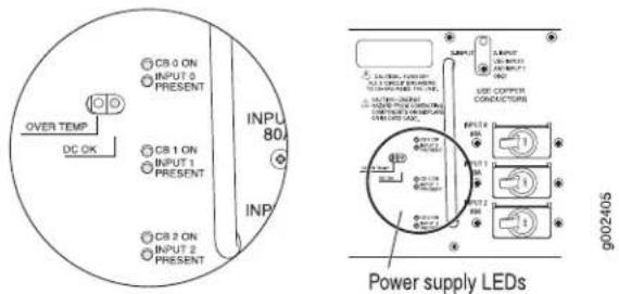
Table 65: Three-Input 240-A DC Power Supply LEDs
| DescriptionStateColorLED | |||
| input | Circuit breaker is on.On steadilyGreenCB ON-One | ||
| Off | Circuit breaker is not turned on, or host subsystem has detected a failure and has turned the circuit breaker off. | ||
| power supply | On steadilyBlueDC | OKHeOne the power supply is correctly set to three-input mode and all three inputs are properly energized, the DC OK LED indicates that the power supply is functioning normally. | |
| Blinking | Power supply is starting up, is not functioning, is not properly installed, or is not operating properly. | ||
| PRESENT-One per input | Input is receiving voltage.On steadilyGreenINPUT | ||
| Input voltage is not present.Off | |||
| TEMP-One per power supply | OVER On steadilyYellow | Power supply has exceeded recommended temperature. | |
| Off | Power supply is within the recommended temperature or the power supply is not on. | ||
Related Documentation
• T1600 Three-Input 240-A DC Power Supply Description on page 106
• T1600 DC Power Requirements on page 140
- Maintaining the T1600 Power Supplies on page 490
- Troubleshooting the T1600 Power System on page 516
T1600 Four-Input 240-A DC Power Supply Description
• Four-Input 240-A DC Power Supply on page 109
• Four-Input 240-A DC Power Supply Inputs on page 110
• Four-Input 240-A DC Power Supply Load Sharing and Fault Tolerance on page 110
Four-Input 240-A DC Power Supply
Each four-input 240-A DC power supply weighs approximately 26.6 lb (12.0 kg) and consists of four inputs, four 60-A circuit breakers, a fan, and LEDs to monitor the status of the power supply. Figure 41 on page 110 shows the four-input 240-A DC power supply.
Figure 41: Four-Input 240-A DC Power Supply

Four-Input 240-A DC Power Supply Inputs
The four-input 240-A DC power supply inputs are labeled INPUT 0, INPUT 1, and INPUT 2, and INPUT 3 from top to bottom. Each input consists of -48 VDC and return, each with its own 60-A circuit breaker.
Table 66 on page 110 describes which components are powered by each input.
Table 66: Components Powered by Each Four-Input 240-A DC Power Supply Input
| ComponentsInput | |
| SIBs, control boards, Routing Engines, and half the system fan powerINPUT ( | |
| INPUT1 | FPCs in slots FPC0 and FPC1 and half the system fan power |
| FPCs in slots FPC2 through FPC4INPUT 2 | |
| FPCs in slots FPC5 through FPC7INPUT 3 |
Four-Input 240-A DC Power Supply Load Sharing and Fault Tolerance
When the router is operating normally and both power supplies are switched on, load sharing between them occurs automatically. When one power supply fails or is turned off, the other power supply immediately assumes the entire electrical load for the system. A single power supply can provide full power for as long as the router is operational. If any of the four inputs fails, the router shuts down, and the other power supply assumes the electrical load for all four inputs.
Related Documentation
T1600 Power System Description on page 105.
•T1600 Four-Input 240-A DC Power Supply LEDs on page 111
- Maintaining the T1600 Power Supplies on page 490
•Troubleshooting the T1600 Power System on page 516
.T1600 DC Power Requirements on page 140
T1600 Four-Input 240-A DC Power Supply LEDs
LEDs on each four-input 240-A DC power supply faceplate (see Table 67 on page 111) indicate the status of the power supply. In addition, a power supply failure triggers the red alarm LED on the craft interface. Figure 42 on page 111 displays the power supply LEDs.
Figure 42: Four-Input 240-A DC Power Supply LEDs
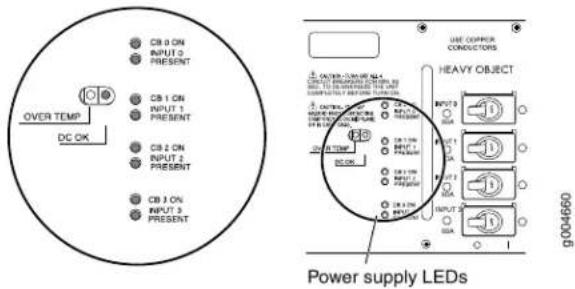
Table 67: Four-Input 240-A DC Power Supply LEDs
| DescriptionStateColorLED | |||
| PRESENT-One per input | Input is receiving voltage.On steadilyGreenINPUT | ||
| Input voltage is not present.Off | |||
| input | Circuit breaker is on.On steadilyGreenCB ON-One | ||
| Off | Circuit breaker is not turned on, or host subsystem has detected a failure and has turned the circuit breaker off. | ||
| power supply | On steadilyBlueDC OKOne all four inputs are properly energized, the DC OK LED indicates that the power supply is functioning normally. | ||
| Blinking | Either the power supply is starting up, or it is not functioning, not properly installed, or not operating properly. | ||
| TEMP-One per power supply | OVER On steadilyYellow | Power supply has exceeded recommended temperature. | |
| Off | Power supply is within the recommended temperature or the power supply is not on. | ||
Related Documentation T1600 Four-Input 240-A DC Power Supply Description on page 109. •T1600 DC Power Requirements on page 140 •Maintaining the T1600 Power Supplies on page 490 •Troubleshooting the T1600 Power System on page 516
T1600 Six-Input DC Power Supply Description
• Power Supply Components on page 112
- Inputs on page 112
• Redundancy on page 113
Power Supply Components
Each six-input DC power supply weighs approximately 39.7 lb (18.0 kg) and consists of six inputs, two blowers, a front and side air filter, and LEDs to monitor the status of the power supply. Each power supply is cooled by its own internal cooling system.
Figure 43 on page 112 shows the six-input DC power supply.

NOTE: There are no circuit breakers or passive fuses in the router.
Figure 43: Six-Input DC Power Supply

Inputs
The six-input DC power supply inputs are labeled INPUT 0, INPUT 1, INPUT 2, INPUT 3, INPUT 4, and INPUT 5, from top to bottom. Each 60 A input consists of -48 VDC and return.
Table 68 on page 113 describes which components are powered by each input.
Table 68: ComponentsPoweredby Each Six-Input DC Power SupplyInput
| ComponentsInput |
Fan traysINPUT 0
INPUT 1 through INPUT 5 FPCs, Routing Engines, control boards, SIBs, craft interface, SCGs, and other components in the router.
Redundancy
When the router is operating normally and both power supplies are switched on, load sharing between them occurs automatically. When one power supply fails or is turned off, the other power supply immediately assumes the entire electrical load for the system. A single power supply can provide full power for as long as the router is operational.
Related Documentation
T1600 Power System Description on page 105.
•T1600 Six-Input DC Power Supply LEDs on page 113
- Maintaining the T1600 Power Supplies on page 490
•Troubleshooting the T1600 Power System on page 516
•T1600 DC Power Requirements on page 140
T1600 Six-Input DC Power Supply LEDs
LEDs on each six-input DC power supply faceplate indicate the status of the power supply. In addition, a power supply failure triggers the red alarm LED on the craft interface. Table 69 on page 113 displays the power supply LEDs.
Table 69: Six-Input DC Power Supply LEDs
| DescriptionStateColorLED | |||
| INPUT PRESENT-One per input | Green | On steadily | Input is receiving voltage. |
| Off | Input voltage is not present. | ||
| DC OK-One per power supply | Blue | On steadily | When all inputs are properly energized, the DC OK LED indicates that the power supply is functioning normally. |
| Blinking | Either the power supply is starting up, or it is not functioning, not properly installed, or not operating properly. | ||
| TEMP-One per power supply | On steadilyYellowOVERwer supply has exceeded recommended temperature. | ||
| Off | Power supply is within the recommended temperature or the power supply is not on. | ||
Related Documentation
T1600 Six-Input DC Power Supply Description on page 112.
•T1600 DC Power Requirements on page 140
•Maintaining the T1600 Power Supplies on page 490
•Troubleshooting the T1600 Power System on page 516
T1600 Three-Phase Delta and Wye AC Power Supply Description
• Three-Phase Delta AC Power Supply on page 114
• Three-Phase Wye AC Power Supply on page 115
• AC Power Supply Load Sharing and Fault Tolerance on page 116
Three-Phase Delta AC Power Supply
Each three-phase delta AC power supply weighs approximately 31.0 lb (14.06 kg). A metal wiring compartment contains the AC terminal block and ground labeled GND. The AC terminal block consists of three input terminals labeled L1, L2, and L3, from left to right. The power switch provides power to the router. Each power supply's cooling system consists of two fans, a front air filter, and a side air filter. LEDs provide the status of the power supply. Figure 44 on page 114 shows the three-phase delta AC power supply.
Figure 44: Three-Phase Delta AC Power Supply

natural_image
Technical line drawing of an industrial power supply unit with fan and pipe components (no text or symbols)Figure 45 on page 115 shows the three-phase delta AC power supply connections.
Figure 45: Three-Phase Delta AC Power Supply Connections
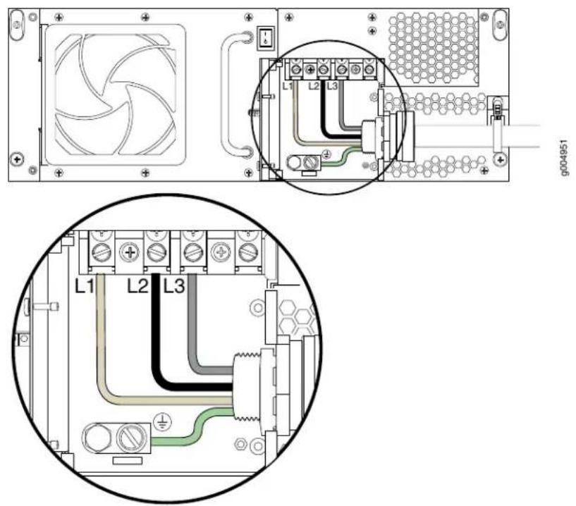
Figure 46 on page 115 shows the three-phase delta AC power cord.
Figure 46: Three-Phase Delta AC Power Cord

natural_image
Technical line drawing of two types of electrical connectors: a multi-pin connector with black, gray, and beige wires and a multi-pin connector with green wires (no text or symbols)Three-Phase Wye AC Power Supply
Each three-phase wye AC power supply weighs approximately 31.0 lb (14.06 kg). A metal wiring compartment contains the AC terminal block and ground labeled GND. The AC terminal block consists of four input terminals labeled L1, L2, L3, and N, from left to right.
The power switch provides power to the router. Each power supply's cooling system consists of two fans, a front air filter, and a side air filter. LEDs provide the status of the power supply. Figure 47 on page 116 shows the three-phase wye AC power supply.
Figure 47: Three-Phase Wye AC Power Supply

natural_image
Technical line drawing of an industrial power supply unit with fan, cooling pipes, and pipe connection (no text or symbols)Figure 48 on page 116 shows the three-phase wye AC power supply connections.
Figure 48: Three-Phase Wye AC Power Supply Connections

Figure 49 on page 116 shows the three-phase wye AC power cord.
Figure 49: Wye Three-Phase AC Power Cord
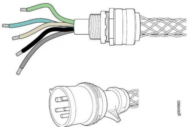
natural_image
Technical line drawing of a multi-core cable with exposed wires and connectors, plus a close-up of its internal structure (no text or symbols)AC Power Supply Load Sharing and Fault Tolerance
When the router is operating normally and both power supplies are switched on, load sharing between them occurs automatically. When one power supply fails or is turned
off, the other power supply immediately assumes the entire electrical load for the system. A single power supply can provide full power for as long as the router is operational.
Related Documentation
T1600 Power System Description on page 105.
•T1600 Three-Phase Delta and Wye AC Power Supply LEDs on page 117
•Maintaining the T1600 Power Supplies on page 490
•Troubleshooting the T1600 Power System on page 516
•T1600 AC Power Requirements on page 149
•T1600 AC Power Cord Specifications on page 151
T1600 Three-Phase Delta and Wye AC Power Supply LEDs
Figure 50 on page 117 shows the LEDs on each three-phase delta AC power supply faceplate. The three-phase wye AC power supply has the same LEDs. The LEDs in Table 70 on page 117 indicate the status of the power supply. In addition, a power supply failure triggers the red alarm LED on the craft interface.
Figure 50: Delta AC Power Supply LEDs
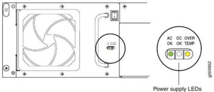
Table 70: Delta AC Power Supply LEDs
| DescriptionStateColorLED | |||
| power supply | On steadilyGreenACTOK-AC terminal block is receiving voltage. | ||
| - | Off | The AC terminal block is not receiving voltage. | |
| power supply | DC OKOrOn stepallyBlue | Power supply is functioning normally. | |
| Blinking | Power supply is starting up, or is not functioning or operating properly, or is not properly installed. | ||
| - | Off | The power supply fails or the AC terminal block is not receiving voltage. | |
| TEMP-One per power supply | - | On steadilyYellowOVERwer supply has exceeded recommended temperature. | |
| - | Off | If the DC OK and AC OK are or steadily, this LED indicates that power supply is within the recommended temperature. | |
Related Documentation
•T1600 Three-Phase Delta and Wye AC Power Supply Description on page 114
•Maintaining the T1600 Power Supplies on page 490
•Troubleshooting the T1600 Power System on page 516
•T1600 AC Power Requirements on page 149
CHAPTER 8
Switch Fabric Components and Descriptions
• T1600 Switch Interface Board (SIB) Description on page 119
• T1600-SIB Description on page 120
• T1600-SIB LEDs on page 121
- TXP-T1600 SIB Description on page 121
• TXP-T1600 SIB LEDs on page 122
• T1600 TXP-LCC-3D SIB Description on page 123
• T1600 TXP-LCC-3D SIB LEDs on page 124
T1600 Switch Interface Board (SIB) Description
SIBs create the switch fabric for the T1600 Core Router. Each T1600 router contains five SIBs located at the center rear of the chassis in the slots labeled SIB0 through SIB4 (top to bottom). One of the five SIBs acts as a backup to the remaining four SIBs. If a SIB fa the backup SIB becomes active, and traffic forwarding continues without any degradation. When the failed SIB is replaced, it becomes the new backup. SIBs are hot-insertable and hot-removable.
The T1600 router supports the SIBs listed in Table 71 on page 119
Table 71: T1600 Supported SIBs
| First Supported Junos OS ReleaseModel N |
8.5SIB-T1600T1600-SIB
NOTE: The T1600-SIB is required for a standalone T1600 router.
9.6R2SIB-TXP-T1600TXP-T1600
NOTE: The TXP-T1600 SIB is required for connection to a TX Matrix Plus router with the TXP-T1600 configuration.
Table 71: T1600 Supported SIBs (continued)
| First Supported Junos OS ReleaseModel N |
13.1SIB-TXP-3D-LCCTXP-LCC-3D
NOTE: The TXP-LCC-3D SIB is required for connection to a TX Matrix Plus router with the TXP-T1600-3D, TXP-T4000-3D, and TXP-Mixed-LCC-3D configurations.
Related Documentation
T1600-SIB Description on page 120.
•TXP-T1600 SIB Description on page 121
•T1600 TXP-LCC-3D SIB Description on page 123
.T1600 Router Description on page 3
T1600-SIB Description
Figure 51 on page 120 shows a T1600-SIB. T1600-SIBs are supported only on standalone T1600 routers. A T1600 router in a routing matrix does not support T1600-SIBs.
Figure 51: T1600-SIB

Each T1600-SIB consists of the following components:
- Switch fabric ASICs.
• High-speed links to each FPC. - SIB online/offline button, located on the SIB faceplate.
- Three LEDs—ACTIVE, OK, and FAIL—located on the SIB faceplate that display the status of the T1600-SIB. The OK and FAIL LEDs are replicated on the craft interface.
Related Documentation
T1600 Switch Interface Board (SIB) Description on page 119.
•T1600-SIB LEDs on page 121
•Maintaining the T1600 SIBs on page 495
•Troubleshooting the T1600 SIBs on page 520
T1600-SIB LEDs
Table 72 on page 121 describes the functions of the T1600-SIB LEDs. If all three LEDs are off, the SIB is not receiving power. The craft interface has three additional LEDs that show the status of each SIB.
Table 72: T1600-SIB LEDs
| DescriptionStateColorLabel | |||
| SIB is in active mode.On steadilyGreenACTIVE | |||
| SIB is functioning normally.On steadilyGreenOK | |||
| SIB is starting up.Blinking | |||
| SIB has failed.On steadilyYellowFAIL | |||
Related Documentation
T1600 Switch Interface Board (SIB) Description on page 119
•T1600-SIB Description on page 120
•Maintaining the T1600 SIBs on page 495
•Troubleshooting the T1600 SIBs on page 520
TXP-T1600 SIB Description
Figure 52 on page 121 shows a TXP-T1600 SIB. A T1600 router in a routing matrix requires TXP-T1600 SIBs. Each TXP-T1600 SIB weighs 10.2 lb (4.6 kg).
Figure 52: TXP-T1600 SIB
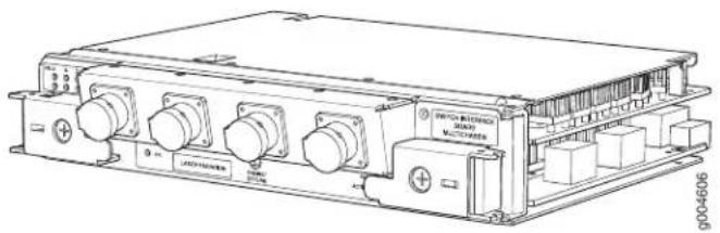
natural_image
Technical line drawing of an electronic device chassis with multiple ports and connectors (no text or symbols visible)Each TXP-T1600 SIB consists of the following components:
-
Switch fabric ASICs.
• High-speed links to each FPC. -
SIB online/offline button, located on the SIB faceplate.
- Three LEDs located on the SIB faceplate that display the status of the T1600-SIB. The OK and FAIL LEDs are replicated on the craft interface.
Related
Documentation
T1600 Switch Interface Board (SIB) Description on page 119.
•TXP-T1600 SIB LEDs on page 122
•Maintaining the T1600 SIBs on page 495
•Troubleshooting the T1600 SIBs on page 520
TXP-T1600 SIB LEDs
Table 73 on page 122 describes the functions of the T1600-SIB LEDs. If all three LEDs are off, the SIB is not receiving power. The craft interface has three additional LEDs that show the status of each SIB.
Table 73: TXP-T1600 SIB LEDs
| DescriptionStateColorLabel | |||
| SIB is in active mode.On steadilyGreenACTIVE | |||
| On steadilyGreenActioning normally. | |||
| Blinking SIB is starting up. | |||
| FADn steadilyYellow was failed. | |||
The port LEDs—labeled A, B, C, D—are located in the upper left corner of the TXP-T1600 SIB. Figure 53 on page 122 shows the port LEDs. Table 74 on page 123 describes the functions of these LEDs.
Figure 53: TXP-T1600 SIB Port LEDs

Table 74: TXP-T1600 SIB Port LEDs
| DescriptionStateColorLabel | ||
| On steadilyGreenLINK | The link between the TXP-F13 SIB port and the TXP-T1600 SIB port has been established successfully. | |
| Blinking | The link between the TXP-T1600 SIB port and the loopback connector has been established successfully. | |
| The link is being established.On steadilyYellow | ||
| Blinking | The fiber-optic array cable might be connected to either the wrong TXP-T1600 SIB port or wrong TXP-F13 port. | |
| On steadilyRed | The link between the TXP-F13 SIB port and the TXP-T1600 SIB port failed. There might be a hardware problem, or the fiber-optic port or cable might need to be cleaned. | |
| -Off | The cable is not connected on both sides, or either the SIB or TXP-T1600 SIB is powered off. | |
| Full optical power is being received.On steadilyGreenRxPWR | ||
| On steadilyYellow | Diminished optical power is being received. The fiber-optic array cable or the fiber-optic array port might need cleaning, or the cable might be damaged. | |
| -Off | No optical power has been received. The fiber-optic array cable is not connected to the TXP-F13 SIB port, or not connected to the TXP-T1600 SIB port. If the cable is connected on both sides, the cable might be cut. |
Related Documentation
T1600 Switch Interface Board (SIB) Description on page 119.
• TXP-T1600 SIB Description on page 121
- Maintaining the T1600 SIBs on page 495
- Troubleshooting the T1600 SIBs on page 520
T1600 TXP-LCC-3D SIB Description
Figure 54 on page 124 shows a TXP-LCC-3D SIB (model number SIB-TXP-3D-LCC) that is required to connect a T1600 line card chassis (LCC) to TXP-F13-3D SIBs in a TX Matrix Plus Router.
Figure 54: TXP-LCC-3D SIB
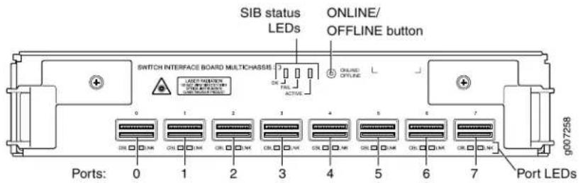
Each TXP-LCC-3D SIB consists of the following components:
• Eight ports labeled 0 through 7. Each port has a CBL and LINK LED.
- Switch fabric ASICs.
• High-speed links to each FPC.
- SIB online/offline button, located on the SIB faceplate. The button is to signal a removal request by a user.
- Three LEDs—OK, FAIL, and ACTIVE—located on the SIB faceplate that display the status of the TXP-LCC-3D SIB. The OK and FAIL LEDs are replicated on the craft interface.
Related Documentation
T1600 Switch Interface Board (SIB) Description on page 119.
.T1600 TXP-LCC-3D SIB LEDs on page 124
•Maintaining the T1600 SIBs on page 495
•Replacing a T1600 TXP-LCC-3D SIB on page 456
•Troubleshooting the T1600 SIBs on page 520
T1600 TXP-LCC-3D SIB LEDs
Table 75 on page 125 describes the functions of the TXP-LCC-3D SIB LEDs (see Figure 55 on page 125). If all three LEDs are off, the SIB is not receiving power. The craft interface has three additional LEDs that show the status of each SIB.
Figure 55: TXP-3D-LCC SIB LEDs
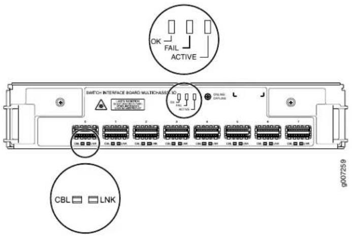
Table 75: TXP-LCC-3D SIB LEDs
| DescriptionStateColorLabel | |||
| SIB is in active mode.On steadilyGreenACTIVE | |||
| Off | SIB is in standby mode. | ||
| NOTE: This LED has significance only if the ONLINE LED is lit. | |||
| SIB is functioning normally.On steadilyGreenOK | |||
| SIB is starting up.Blinking | |||
| SIB has been inserted or is ready for removal.Off | |||
| SIB has failed on steadilyRed | |||
| SIB is functioning normally.Off |
The TXP-LCC-3D SIB port LEDs are located beneath each port. Each port has a Link and CBL LED. Table 76 on page 126 describes the functions of these LEDs.
Table 76: TXP-LCC-3D SIB Port LEDs
| DescriptionStateColorLabel | ||
| On steadilyGreenLINKThe link between the TXP-F13-3D SIB port and the TXP-LCC-3D SIB port has been established successfully. | ||
| Blinking | The link between the TXP-LCC-3D SIB port and the loopback connector has been established successfully. | |
| The link is being established.On steadilyYellow | ||
| Blinking | The switching plane cable might be connected to either the wrong TXP-LCC-3D SIB port or the wrong TXP-F13-3D port. | |
| On steadilyRed | The link between the TXP-F13-3D SIB port and the TXP-LCC-3D SIB port failed.There might be a hardware problem, or the fiber-optic port or cable might need to be cleaned. | |
| - | Off | The cable is not connected on both sides, or either the TXP-F13-3D SIB or the TXP-LCC-3D SIB is powered off. |
| Full optical power is being received.On steadilyGreenCBL | ||
| On steadilyYellow | Diminished optical power is being received. The switching plane cable or the switching plane port might need cleaning, or the cable might be damaged. | |
| OffRed | Optical power has crossed operating thresholds. The switching plane cable is not connected to the TXP-F13-3D SIB port, or is not connected to the TXP-LCC-3D SIB port. If the cable is connected on both sides, the cable might be cut. | |
| No optical power is detected. Cable is damageOff or absent.- | ||
Related Documentation
• T1600 Switch Interface Board (SIB) Description on page 119
• T1600 TXP-LCC-3D SIB Description on page 123
- Maintaining the T1600 SIBs on page 495
- Troubleshooting the T1600 SIBs on page 520
PART 2
Site Planning, Preparation, and Specifications
• Preparation Overview on page 129
• DC Power Specifications and Requirements on page 137
• AC Power Specifications and Requirements on page 147
• Network Cable and Transceiver Specifications on page 155
- Management Cable Specifications and Pinouts on page 167
CHAPTER 9
Preparation Overview
• T1600 Site Preparation Requirements Checklist on page 129
• T1600 Environmental Specifications on page 130
• T1600 Physical Specifications on page 131
• T1600 Chassis Grounding Cable and Lug Specifications on page 132
- Rack Requirements for the T1600 Router on page 133
- Clearance Requirements for Airflow and T1600 Hardware Maintenance on page 135
T1600 Site Preparation Requirements Checklist
The checklist in Table 77 on page 129 summarizes the tasks you need to perform when preparing a site for router installation.
Table 77: Site Preparation Checklist
| DatePerformed | ||
| Environment | ||
| Verify that environmental factors such as "T1600 Environmental temperature and humidity do not exceed router specifications" on page 130 tolerances. | ||
| Power | ||
| Measure distance between external power sources and router installation site. | "T1600 DC Power Distribution" on page 143 | |
| Locate sites for connection of system grounding. | "T1600 Chassis Grounding Cable and Lug Specifications" on page 132 | |
| Calculate the power consumption and requirements. | "T1600 AC Power Requirements" on page 149 "T1600 DC Power Requirements" on page 140 | |
| Rack | ||
| Verify that your rack meets the minimum "Rack Requirements for the T1600 requirements for the installation of the router" on page 133 | ||
| Plan rack location, including required space clearances. | “Clearance Requirements for Airflow and T1600 Hardware Maintenance” on page 135 | |
| If a rack is used, secure rack to floor and structure. | Building Requirements for the T1600 Router” on page 133 | |
| Cables and Transceivers | ||
| Acquire cables and transceivers: ·Determine the number of cables needed based on your planned configuration. ·Review the maximum distance allowed for each cable. Choose the length of cable based on the distance between the hardware components being connected. | “Supported Network Interface Standards by Transceiver for the ACX, M, MX, and T Series” on page 155 “Understanding Fiber-Optic Cable Signal Loss, Attenuation, and Dispersion” on page 162 “Calculating Power Budget and Power Margin for Fiber-Optic Cables” on page 163 | |
| Plan the cable routing and management. | “Maintaining T1600 PICs and PIC Cables” on page 488 | |
T1600 Environmental Specifications
Table 78 on page 130 specifies the environmental specifications required for normal router operation. In addition, the site should be as dust-free as possible.
Table 78: Router Environmental Specifications
| ValueDescription | |
| No performance degradation to 10,000 ft (3048 m)Altitude | |
| Relative humidity | Normal operation ensured in relative humidity range of 5% to 90%, noncondensing |
| Temperature | Normal operation ensured in temperature range of 32°F (0°C) to 104°F (40°C)Nonoperating storage temperature in shipping crate: -40°F (-40°C) to 158°F (70°C) |
| Seismic | Designed to meet Telcordia Technologies Zone 4 earthquake requirements |
| DC power: 28,498 BTU/hour (8350 W)Maximum thermal output |

NOTE: Install the routeronly in restricted areas, such asdedicatedequipment rooms and equipment closets, in accordance with Articles 110-16, 110-17, and 110-18 of the National Electrical Code, ANSI/NFPA 70.
Related Documentation
General Safety Guidelines for Juniper Networks Devices on page 549.
•T1600 Router Description on page 3
T1600 Physical Specifications
Table 79 on page 131 lists the T1600 router's physical specifications.
Table 79: T1600 Physical Specifications
| ValueDescription | |
| Chassis dimensions | 37.45 in. (95.1 cm) high17.43 in. (44.3 cm) wide31 in. (78.7 cm) deepTotal depth (including front cable management system)35.5 in. (90.2 cm)Total depth (including front cable management system and the optional rear cable management system) 45 in.(114.3 cm)11.5 in. (29.2 cm) from front of chassis to center-mounting brackets |
| Router weight | Chassis with midplane: 205 lb (93 kg)Minimum configuration: 387 lb (176 kg)Maximum configuration: 606 lb (275 kg) |
| 2.4 lb (1 kg)Routing Engine weight | |
| 2 lb (1 kg)Craft interface weight | |
| FPC weight | FPCs with PICs installed: Up to 37 lb (17 kg)FPC without PICs installed: up to 25 lb (11 kg)Blank panel in FPC slot: 9 lb (4.0 kg) |
| 8 lb (4 kg)CIP weight | |
| supply weight | 25 lb each (11 kg)Three-input 240-A DC power |
| supply weight | 26.6 lb (12.0 kg)Four-input 240-A DC power39.7 lb (18.0 kg)Six-input DC power supply weight |
| 36.0 lb (16.3 kg)Delta AC power supply weight | |
| 36.6 lb (16.6 kg)Wye AC power supply weight | |
| 1 lb (0.45 kg)Air filter weight | |
| 6.5 lb each (3 kg)T1600-SIB weight | |
| 10.2 lb each (4.6 kg)TXP-T1600 SIB weight | |
| 9.4 lb each (4.2 kg)TXP-3D-LCC-SIB weight | |
| 5 lb each (2 kg)T-CB weight | |
| 5 lb each (2 kg)LCC-CB weight | |
| 1.9 lb each (1 kg)SCG weight | |
| Standard rear fan tray weight10 lb (4.5 kg) | |
| Standard front fan tray weight18.6 lb (8.5 kg) | |
| Quiet rear fan tray weight 10 lb (4.5 kg) | |
| Quiet front fan tray weight 17.8 lb (8.1 kg) | |
| FAN-R-TXP-3D-LCC rear fan tray lb (5.9 kg) | |
| FANTRAY-T4000 front fan tray 0.4 lb (9.3 kg) | |
| Cable management weight 5 lb (2 kg) |
Related Documentation
T1600 Router Description on page 3
• T1600 Chassis Description on page 19
• T1600 Chassis Lifting Guidelines on page 559
T1600 Chassis Grounding Cable and Lug Specifications
To meet safety and electromagnetic interference (EMI) requirements and to ensure proper operation, the router must be adequately grounded before power is connected. Two pairs of threaded inserts (PEM nuts) are provided on the right rear of the chassis for connecting the router to earth ground. The left pair of grounding points fits M6 screws
(European), and the right pair fits UNC 1/4–20 screws (American). The grounding points are spaced at 0.625-in. (15.86-mm) centers.
You must supply a grounding cable. The grounding cable must be 8-AWG ^2 , (8.35 mm minimum 90°C wire, or as required by the local code.
The accessory box shipped with the router includes one 4-AWG ^2 cable ring that attaches to the grounding cable (see Figure 56 on page 133). (The cable lug shown in Figure 56 on page 133 is also used for the DC power cables.) The accessory box includes two UNC 1/4–20 screws used to secure the grounding cable to the right pair of grounding points.

CAUTION: Before router installation begins, a licensed electrician must attach a cable lug to the grounding cable that you supply. A cable with an incorrectly attached lug can damage the router.
Figure 56: Grounding Cable Lug

Related Documentation
Connecting the T1600 Grounding Cable on page 228.
•T1600 DC Power System Electrical Specifications on page 137
Rack Requirements for the T1600 Router
The router can be installed in many types of racks, including four-post (telco) racks and open-frame racks. An example of an open-frame rack is shown in Figure 57 on page 134.
For open-frame racks, center-mounting is preferable to front-mounting because the more even distribution of weight provides greater stability.
The router is designed for installation in a 19-in. rack as defined in Cabinets, Racks, Panels, and Associated Equipment (document number EIA-310-D) published by the Electronics Industry Association (http://www.eia.org).
With the use of adapters, the router can fit into a 600-mm-wide rack, as defined in the four-part Equipment Engineering (EE); European Telecommunications Standard for Equipment Practice (document numbers ETS 300 119-1 through 119-4) published by the European Telecommunications Standards Institute (http://www.etsi.org). Use approved wing devices to narrow the opening between the rails.
The rack rails must be spaced widely enough to accommodate the router chassis's external dimensions: 37.45 in. (95.1 cm) high, 31 in. (78.7 cm) deep, and 17.43 in. (44.3 cm)
wide, excluding the front and rear cable management systems. The outer edges of the mounting brackets extend the width to 19 in. (48.3 cm). The spacing of rails and adjacent racks must also allow for the clearances around the router and rack.
The mounting holes for connecting the mounting brackets to the chassis are spaced 0.984 in. (25 mm) apart.
The chassis height of 37.45 in. (95.1 cm) is approximately 21.4 U. A U is the standard rack unit defined in Cabinets, Racks, Panels, and Associated Equipment (document number EIA-310-D) published by the Electronics Industry Association. You can stack two routers in a rack that has at least 42.8 U (74.9 in. or 1.90 m) of usable vertical space.
The rack must be strong enough to support the weight of the fully configured router, up to 606 lb (275 kg). If you stack two fully configured routers in one rack, it must be capable of supporting about 1212 lb (550 kg).
Figure 57: Typical Open-Frame Rack
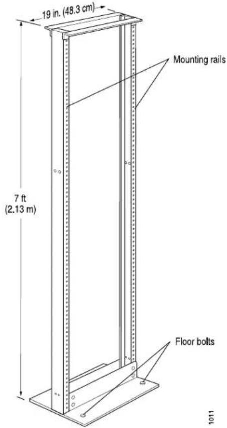
Always secure the rack to the structure of the building. If your geographical area is subject to earthquakes, bolt the rack to the floor. For maximum stability, also secure the rack to ceiling brackets.
Related Documentation
Clearance Requirements for Airflow and T1600 Hardware Maintenance on page 135.
• Installation Safety Warnings for Juniper Networks Devices on page 559
•T1600 Router Description on page 3
Clearance Requirements for Airflow and T1600 Hardware Maintenance
When planning the installation site, you need to allow sufficient clearance around the rack (see Figure 58 on page 135):
- For the cooling system to function properly, the airflow around the chassis must be unrestricted.

NOTE: If you mount the router in a cabinet, be sure that ventilation is sufficient to prevent overheating.
- For service personnel to remove and install hardware components, there must be adequate space at the front and back of the router. At least 24 in. (61 cm) are required both in front of and behind the router. NEBS GR-63 recommends that you allow at least 30 in. (72.6 cm) behind the rack.
• Additional clearance is required to accommodate the width and depth of the chassis with the optional rear cable management system:
• 2.4 in. (6.2 cm) additional width on the left side of the chassis
• 9.5 in. (24.1 cm) additional depth in the rear of the chassis
Figure 58: Chassis Dimensions and Clearance Requirements

Related Documentation
•T1600 Chassis Description on page 19
•T1600 Rear Cable Management System Description on page 23
•T1600 Cooling System Description on page 37
•Rack Requirements for the T1600 Router on page 133
CHAPTER 10
DC Power Specifications and Requirements
• T1600 DC Power System Electrical Specifications on page 137
• T1600 Three-Input 240-A DC Power Supply Specifications on page 138
• T1600 Four-Input 240-A DC Power Supply Specifications on page 139
• T1600 Six-Input DC Power Supply Specifications on page 140
• T1600 DC Power Requirements on page 140
• T1600 DC Power Distribution on page 143
• T1600 DC Power Cables and Lugs on page 144
T1600 DC Power System Electrical Specifications
Table 80 on page 137 lists the DC power system electrical specifications.
Table 80: Power System Electrical Specifications
| SpecificationItem | |
| DC input voltage | Operating range: -40.0 to -72.0 VDCNOTE: If the input voltage from the DC power source drops below -37.5 to -39.5 VDC, the routing platform automatically shuts down. During automatic shutdown, the circuit remains active. When the input voltage returns to -43.0 to -44.0 VDC, the router automatically starts up again and the system returns to normal operation within 30 minutes. No operator intervention is required. |
| 174 A @ -48 VDC (nominal) (8350 W)DC system current |
For each three-input 240-A DC power supply, we recommend that you provision at least 67 A @ -48 VDC per input. Although Input 0 in the three-input 240-A DC power supply requires less power, we recommend provisioning the same amount of power for each input to avoid the possibility of connecting the lower-powered DC cable to Input1 or Input2.
For each four-input 240-A power supply, we recommend that you provision at least 50 A @ -48 VDC per input. Although Input 0 and Input 1 in the four-input 240-A power supply require less power, we recommend provisioning the same amount of power for each input to avoid the possibility of connecting the lower-powered DC cables to Input 2 or Input 3.
For each six-input DC power supply, we recommend that you provision at least 56 A @ -48 VDC per input. Although Input 0 in the six-input DC power supply requires less power we recommend provisioning the same amount of power for each input to avoid the possibility of connecting the lower-powered DC cables to Input 1 through Input 5.
You must provision a circuit breaker for each DC power supply input rated for at least 125% of the continuous current that the system draws at -48 VDC.
Related Documentation
T1600 Power System Description on page 105.
- Connecting DC Power to the T1600 Router (Three-Input 240-A DC Power Supplies or Four-Input 240-A DC Power Supplies) on page 240
•T1600 Site Preparation Requirements Checklist on page 129
T1600 Three-Input 240-A DC Power Supply Specifications
Table 81 on page 138 lists the three-input 240-A DC power supply electrical specifications.
Table 81: Power Supply Electrical Specifications
| SpecificationItem | |
| DC input voltage | Nominal -48 VDC, -60 VDCOperating range: -40.0 to -72.0 VDCNOTE: If the input voltage from the DC source drops below -37.5 to -39.5 VDC, t routing platform automatically shuts down, During automatic shutdown, the circuit rem active. When the input voltage returns to -44.00 VDC, the router automatically sup again and the system returns to norm operation within 30 minutes. No operator intervention is required. |
| Input DC current rating | Part number:Input 0: 47 A @ -48 VDC (nominal) (2256 W)Input 1: 67A@-48VDC(nominal)(3216W)Input 2: 67 A @ -48 VDC (nominal) (3216 W)Part number:Input 0: 54 A @ -48 VDC (nominal) (2592 W)Input 1: 67A@-48VDC(nominal)(3216W)Input 2: 67 A @ -48 VDC (nominal) (3216 W) |
Related Documentation
T1600 Power System Description on page 105.
•T1600 Three-Input 240-A DC Power Supply Description on page 106
•T1600 DC Power System Electrical Specifications on page 137
T1600 Four-Input 240-A DC Power Supply Specifications
Table 82 on page 139 lists the four-input 240-A DC power supply electrical specifications.
Table 82: Four-Input 240-A DC Power Supply Electrical Specifications
| SpecificationItem | |
| DC input voltage | Nominal -48 VDC, -60 VDCOperating range: -40.0 to -72.0 VDCNOTE: If the input voltage from the DC power source drops below -37.5 to -39.5 VDC, the router automatically shuts down. During automatic shutdown, the circuit remains active.When the input voltage returns to -43.0 to -44.00 VDC, the router automatically starts up again and the system returns to normal operation within 30 minutes. No operator intervention is required. |
| Input DC current rating | Input 0: 47 A @ -48 VDC (nominal) (2256 W)Input 1: 44 A @ -48 VDC (nominal) (2112 W)Input 2: 50 A @ -48 VDC (nominal) (2400 W)Input 3: 50 A @ -48 VDC (nominal) (2400 W) |
Related Documentation
T1600 Power System Description on page 105.
•T1600 Four-Input 240-A DC Power Supply Description on page 109
•T1600 DC Power System Electrical Specifications on page 137
T1600 Six-Input DC Power Supply Specifications
Table 83 on page 140 lists the six-input DC power supply electrical specifications.
Table 83: Six-Input DC Power Supply Electrical Specifications
| SpecificationItem | |
| DC input voltage | Nominal -48 VDC, -60 VDCOperating range: -40.0 to -72.0 VDCNOTE: If the input voltage from the DC power source below -37.5 to -39.5 VDC, the router automatically shut During automatic shutdown, the circuit remains active. The input voltage returns to -43.0 to -44.00 VDC, the automatically starts up again and the system returns to operation within 30 minutes. No operator intervention is required. |
| Input DC current rating | Input 0: 45 A @ -48 VDC (nominal) (2160 W)Input 1: 56 A @ -48 VDC (nominal) (2448 W)Input 2: 56 A @ -48 VDC (nominal) (2448 W)Input 3: 56 A @ -48 VDC (nominal) (2448 W)Input 4: 56 A @ -48 VDC (nominal) (2448 W)Input 5: 56 A @ -48 VDC (nominal) (2448 W) |
Related Documentation
T1600 Power System Description on page 105. •T1600 DC Power System Electrical Specifications on page 137
T1600 DC Power Requirements
To allow for future growth so that you can operate the router in any hardware configuration without upgrading the power infrastructure, we recommend that you provision the following for each power supply.

NOTE: Although the power requirements for each input varies, we recommend that you provision the same amount of power for each input, or DC power cable when using terminal jumpers.
- Three-input 240-A DC power supply: 67 A @ -48 VDC per input
- Four-input 240-A power supply: 50 A @ -48 VDC per input
- Six-input power supply: 56 A @ -48 VDC per input
Table 84 on page 141 lists the power requirements for various hardware components. For PIC power requirements, see the T1600 Core Router Interface Module Reference.
You can use the information in Table 84 on page 141 and the T1600 Core Router Interface Module Reference to calculate power consumption for various hardware configurations, input current from a different source voltage, and thermal output, as shown in the following examples for a DC-powered router.
Table 84: Typical DC Power Requirements for T1600 Components
| Current Requirement (Amps @ -48 VDC)Comp | |
| 30.9 ABase system, not including host subsystem, one SCG, two three-input 240-A power supplies or two four-input 240-A power supplies, cooling system at normal speed, and craft interface) | |
| 31.1 ABase system, not including F one host subsystem, one SCG, two six-input power supplies, cooling system with FAN-R-TXP-3D-LCC rear fan tray at normal speed, and craft interface) | |
| 3.6 AT1600-SIB | |
| 4.1 ATXP-1600 SIB | |
| 4.2 ATXP-LCC-3D SIB | |
| 3.4 AEnhanced II FPC1 | |
| 7.1 AEnhanced Scaling FPC1 | |
| 3.4 AFPC2 and Enhanced II FPC2 | |
| 6.8 AFPC3, Enhanced FPC3, and I | |
| 9.11 AEnhanced Scaling FPC3 | |
| 8.2 AT640 Enhanced Scaling FPC4 | |
| 11.3 AT1600 Enhanced Scaling FPC5 | |
| 2.6 AHost subsystem (600, 1600, | |
| 1.0 ALine-card chassis control boa | |
| C1800 Routing Engine | 1.7 A0.2 ASCG |
| 1.7 ARedundant backup 3-input 24 | |
| 1.7 ARedundant backup 4-input 24 | |
| 5.2 ARedundant backup 6-input DI | |
| 6.7 ACooling system (normal spee | |
| 22 ACooling system (full speed) | |
| 7.95 ACooling system with FAN-R- | |
| 25.1 ACooling system with FAN-R- | |
| 0.2 ACraft interface | |
| 0.625 APIC-Generalized typical va | |
| 3.3 APIC-Generalized maximum va | |
• Example of calculating power consumption for a minimum configuration:
$$ \begin{array}{l} \text {Base System + 1 Type 3 FPC + 1 PIC =} \ 3 0. 9 A + 6. 8 A + 0. 6 2 5 A = 3 8. 3 3 A @ - 4 8 V D C = 1, 8 4 0 W \end{array} $$
• Example of calculating power consumption for a maximum configuration using TXP-T1600 SIBs:
$$ \begin{array}{l} \text {Base System + 8 T1600 - Type 4 FPCs + 1 LCC - CB + 1 RE - C1800 + 1 SCG + 16 PICs + 5} \ \text {(TXP - T1600 SIBs - T1600 SIBs) =} \ 3 0. 9 A + 8 (1 1. 3 A) + 1. 0 A + 1. 7 A + + 0. 2 A + 1 6 (3. 3 A) + 5 (0. 5) A = \ 3 0. 9 A + 9 0. 4 A + 1. 0 A + 1. 7 A + + 0. 2 A + 5 2. 8 A + 2. 5 A = 1 7 9. 5 A @ - 4 8 V D C = \end{array} $$
- Current requirement adjustment for fans running at full speed (high temperature environment or cooling component failure):
$$ \begin{array}{l} \text { Calculated system current (X) - Cooling (normal) + Cooling (full speed) = } \ \text { X A - 6.7 A + 22 A = X A + 15.3 A } \end{array} $$
- Input current from a DC source other than -48 VDC (based on maximum configuration):
$$ \begin{array}{l} (- 5 4 \text { VDC input }) x (\text { input current } X) = (- 4 8 \text { VDC }) x (\text { input current } Y) \ 5 4 x X = 4 8 x 9 4. 1 A \ X = 4 8 x 9 4. 1 A / 5 4 = 8 3. 6 A \end{array} $$
- Typical system thermal output for maximum configuration:
Watts DC/0.293 = BTU/hr
8616/0.293 = 29,406 BTU/hr
Related Documentation
T1600 Power System Description on page 105.
•T1600 Site Preparation Requirements Checklist on page 129
.T1600 DC Power Distribution on page 143
•T1600 DC Power System Electrical Specifications on page 137
T1600 DC Power Distribution
Most sites distribute DC power through a main conduit that leads to frame-mounted DC power distribution panels, one of which might be located at the top of the rack that houses the router. A pair of cables (one input and one return) connects each set of terminal studs to the power distribution panel.

NOTE: All inputs on the DC power supply in slot PEMO must be powered by dedicated power feeds derived from feed A, and all inputs on the DC power supply in slotPEM1must be powered by dedicated power feeds derived from feed B. This configuration provides the commonly deployed A/B feed redundancy for the system.
Figure 59 on page 143 shows a typical DC source cabling arrangement.
Figure 59: Typical DC Source Cabling to the Router
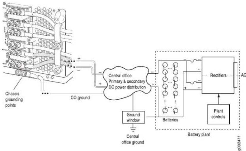
flowchart
graph TD
    A["Chassis grounding points"] --> B["CO ground"]
    B --> C["Central office Primary & secondary DC power distribution"]
    C --> D["Batteries"]
    D --> E["Rectifiers"]
    E --> F["AC"]
    G["Ground window"] --> H["Central office ground"]
    I["Plant controls"] --> J["Battery plant"]
    K["Ground"] --> L["Batteries"]
    M["Ground"] --> N["Batteries"]
Related Documentation
T1600 General Electrical Safety Guidelines on page 575.
•T1600 Power System Description on page 105
T1600 DC Power Cables and Lugs
• DC Power Cables on page 144
• DC Power Lugs on page 145
DC Power Cables
Table 85 on page 144 summarizes the specifications for the power cables, which you must supply.
Table 85: Power Cable Specifications
| Quantity and Specification |
| Three-input 240-A DC power supplies: Twelve 4-AWG ( 2^1 ) _2 minimum 90°C wire, or as required by the local code |
| Four-input 240-A DC power supplies: Sixteen 4-AWG ( 2^1 ) _2 minimum 90°C wire, or as required by the local code |
| Six-input DC power supplies:Six inputs: 24 4-AWG ( 21.2^2 ) _m minimum 90°C wire, or as required by the local codeFive inputs: 20 4-AWG ( 21.2^2 ) _m minimum 90°C wire, or as required by the local codeSix inputs: Sixteen 4-AWG ( 21.2^2 ) _m minimum 90°C wire, or as required by the local code |
Table 86: Number of Cables Required
| Number of DC Cables per Power SupplyPower Supply | |
| 6Three-input 240-A DC power supply | |
| 8Four-input 240-A DC power supply | |
| 12Six-input DC power supply: 6 inputs connected | |
| 10Six-input DC power supply: 5 inputs connected | |
| 10Six-input DC power supply: 5 inputs connected | |
| 8Six-input DC power supply: 4 inputs connected |

WARNING: For field-wiring connections, use copper conductors only.

CAUTION: Power cables must not block access to router components or drape where people could trip on them.

CAUTION: You must ensure that power connections maintain the proper polarity. The power source cables might be labeled (+) and (−) to indicate their polarity. There is no standard color coding for DC power cables. The color coding used by the external DC power source at your site determines the color coding for the leads on the power cables that attach to the terminal studs on each power supply.
DC Power Lugs
The accessory box shipped with the T640 router includes eighteen 4-AWG ^2 (21.2 mm cable lugs for the DC cables that attach to the terminal studs of each power supply (see Figure 60 on page 145). the number of DC cables and cable lugs required varies depending on the power supply (see Table 86 on page 144). Each DC power cable requires one cable lug. One cable lug is also used for grounding the chassis. The cable lugs are dual hole, and sized to fit 1/4-20 UNC terminal studs at 15.86-mm (0.625-in.) center line.
Figure 60: DC Power Cable Lug


CAUTION: Before routerinstallation begins, a licensed electrician must attach a cable lug to the power cables that you supply. A cable with an incorrectly attached lug can damage the router.
Related Documentation
•T1600 Power System Description on page 105
•Connecting DC Power to the T1600 Router (Three-Input 240-A DC Power Supplies or Four-Input 240-A DC Power Supplies) on page 240
•Replacing a T1600 DC Power Supply Cable on a Three-Input 240-A DC Power Supply or Four-Input 240-A DC Power Supply on page 409
- Connecting DC Power to the T1600 Router (Six 60-A Inputs to Six-Input DC Power Supplies) on page 243
- Connecting DC Power to the T1600 Router (Five 60-A Inputs to Six-Input DC Power Supplies) on page 247
- Replacing a T1600 DC Power Supply Cable on a Six-Input DC Power Supply on page 421
•T1600 General Electrical Safety Guidelines on page 575
CHAPTER 11
AC Power Specifications and Requirements
• T1600 AC Power System Specifications on page 147
• T1600 Three-Phase Delta AC Power Supply Specifications on page 148
• T1600 Three-Phase Wye AC Power Supply Specifications on page 148
• T1600 AC Power Requirements on page 149
• T1600 AC Power Cord Specifications on page 151
T1600 AC Power System Specifications
Table 87 on page 147 lists the AC power system electrical specifications.
Table 87: T1600 AC Power System Electrical Specifications
| SpecificationItem | |
| AC input voltage | Delta operating range: 200 - 240 VAC (line-to-line) (nominal)Wye operating range: 346 - 415 VAC (line-to-line) (nominal) |
| AC input line frequency | Delta: 60 Hz (nominal)Wye: 50 Hz (nominal) |
| AC system current rating | Delta: 34 A @ 200 VAC (line-to-line)Wye: 20 A @ 346 VAC (line-to-line) |
| AC system input power | Delta: 11,765 WWye: 11,765 W |
Related Documentation
T1600 Three-Phase Delta and Wye AC Power Supply Description on page 114.
•T1600 Three-Phase Delta AC Power Supply Specifications on page 148
•T1600 Three-Phase Wye AC Power Supply Specifications on page 148
•T1600 AC Power Electrical Safety Guidelines
T1600 Three-Phase Delta AC Power Supply Specifications
Table 88 on page 148 lists the three-phase delta AC power supply electrical specifications.
Table 88: Three-Phase Delta AC Power Supply Electrical Specifications
| SpecificationItem | |
| 10,000 WMaximum output power | |
| Operating range: 200 - 240 VAC (line-to-line) (nominal)AC input voltage | |
| 60 Hz (nominal)AC input line frequency | |
| 28.3 A @ 240 VAC maximum (line-to-line)AC input current rating | |
| 11,765 W per inputMaximum input |
Related Documentation
T1600 Three-Phase Delta and Wye AC Power Supply Description on page 114.
- Connecting AC Power to a T1600 Router with Three-Phase Delta AC Power Supplies on page 253
•T1600 AC Power Electrical Safety Guidelines
•T1600 AC Power Cord Specifications on page 151
T1600 Three-Phase Wye AC Power Supply Specifications
Table 89 on page 148 lists the three-phase wye AC power supply electrical specifications.
Table 89: Three-Phase Wye AC Power Supply Electrical Specifications
| Item | Specification |
| 10,000 WMaximum output power | |
| AC input voltage | Operating range: 346 - 415 VAC (line-to-line) (nominal) |
| AC input line frequency | 50 Hz (nominal) |
| AC input current rating | 16.4 A @ 415 VAC maximum (line-to-line) |
| Maximum input | 11,775 W per input |
Related Documentation
T1600 Three-Phase Delta and Wye AC Power Supply Description on page 114.
- Connecting AC Power to a T1600 Router with Three-Phase Wye AC Power Supplies on page 255
•T1600 AC Power Electrical Safety Guidelines
•T1600 AC Power Cord Specifications on page 151
T1600 AC Power Requirements
To allow for future growth so that you can operate the router in any hardware configuration without upgrading the power infrastructure, we recommend that you provision 11,765 W per each three-phase delta AC power supply or 11,775 W per each three-phase wye AC power supply.
If you do not plan to provision 11,765 W per each three-phase delta AC power supply or 11,775 W per each three-phase wye AC power supply, you can use the information in Table 90 on page 149, Table 91 on page 149, and the T1600 Core Router Interface Module Reference to calculate power consumption for various hardware configurations, input current from a different source voltage, and thermal output, as shown in the following examples for an AC-powered router.
Table 91 on page 149 lists the power requirements for various hardware components when the router is operating under typical voltage conditions. For PIC power requirements, see the T1600 Core Router Interface Module Reference.
Table 90: Base AC Power Requirements
| Power Requirement (Watts) Component | |
| 1774 WBase system, not including FPCs and PICs(includes five T1600-SIBs, one host subsystem[T-CB and 600, 1600, or 2000 Routing Engine],one SCG, cooling system at normal speed, andcraft interface), and two power supplies | |
Table 91: Typical AC Power Requirements for T1600 Components
| Power Requirement (Watts) | Power Requirement (Watts) with 85% Efficiency | |
| 203 W172.8 WT1600-SIB | ||
| 232 W196.8 WTXP-1600 SIB | ||
| Enhanced II FPC1 | 163.2 W | 192 W |
| 401 W340.8 WEnhanced Scaling FPC1 | ||
| FPC2 and Enhanced II FPC2 | 163.2 W | 192 W |
| FPC3 and Enhanced II FPC3 | 326.4 W | 384 W |
| Enhanced Scaling FPC3 | 437.28 W | 514 W |
| T640 Enhanced Scaling FPC4 | 393.6 W | 463 W |
| 638 W542.4 WT1600 Enhanced Scaling FPC | ||
| Engine and T-CB) | 147 W124.8 WHost subsystem (600, 1600, | |
| 56 W48.0 WLine-card chassis control board | ||
| 96 W81.6 WC1800 Routing Engine | ||
| SCG | 11 W9.6 W | |
| Redundant backup three-phase delta AC power Not supply Not applicable | 91 W | |
| Redundant backup three-phase wye AC power Not applicable supply | 91 W | |
| Cooling system (full speed - normal speed) | 864 W1056 W - 321.6 W = 734.4 W | |
| Craft interface | 11 W9.6 W | |
| PIC-Generalized typical value | 30 W | 35 W |
| PIC-Generalized maximum value | 158.4 W | 186 W |
• Example of calculating typical power consumption for minimum configuration:
Base System + 1 FPC3 + 1 PIC = 1774 W + 384 W + 35 W = 2193 W
• Example of calculating typical power consumption for maximum configuration:
Base System + 8 T1600-Type 4 FPCs + 1 LCC-CB + 1 RE-C1800 + 1 SCG + 16 PICs + 5 (TXP-T1600 SIBs - T1600 SIBs) + fan tray (full speed - normal speed) = 1774 W + 8 (638 W) + 56 W + 96 W + 11 W + 16 (186 W) + 5(232 W -203 W) + 86 = 1774 W + 5104 W + 56 W + 96 W +11 W + 2976 W + 145 W + 864 W + 91 W= 11,026
• Example of calculating system thermal output:
Watts DC/0.293 = BTU/hr
11,117/0.293 = 37.631 BTU/hr
Related Documentation
T1600 Power System Description on page 105
- Connecting AC Power to a T1600 Router with Three-Phase Delta AC Power Supplies on page 253
- Connecting AC Power to a T1600 Router with Three-Phase Wye AC Power Supplies on page 255
•T1600 AC Power Electrical Safety Guidelines
•T1600 AC Power Cord Specifications on page 151
T1600 AC Power Cord Specifications
Most sites distribute power through a main conduit that leads to frame-mounted power distribution panels, one of which can be located at the top of the rack that houses the router. An AC power cord connects each power supply to the power distribution panel.
Each AC power supply has a metal wiring compartment that contains the AC terminal block and ground labeled GND. The wye AC terminal block consists of four input terminals labeled L1, L2, L3, and N, from left to right. The delta AC terminal block consists of three input terminals labeled L1, L2, and L3, from left to right.
Detachable AC power cords, each 4.5 m (approximately 14.8 ft) long, are supplied with the router. The AC power cord wires insert into the AC input terminals in the AC terminal block by screwdriver. The plug end of the power cord fits into the power source receptacle for your geographical location.
Table 92 on page 151 provides specifications and Figure 61 on page 152 and
Figure 62 on page 152 depict the plug on the AC power cord provided for each region supported.
Table 92: Three-Phase Delta and Wye AC Power Cord Specifications
| ElectricalSpecificationModel NumberCountry | Plug ColorPlug Type |
RedIEC 6030932 A, 400 VACCBL-T-PWR-ST
| North America | CBL-T-PWR-STR-DELTA | 60 A, 250 VAC | IEC 60309 | Blue |
Figure 61: Three-Phase Delta AC Power Cord
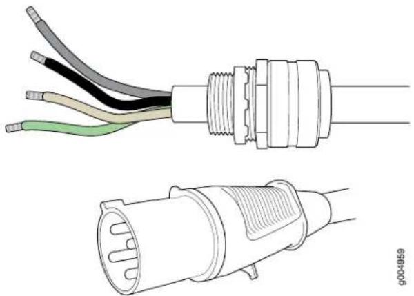
natural_image
Technical line drawing of two types of electrical connectors: a multi-pin connector with black, gray, and beige wires and a wire-wrapped terminal (no text or symbols)Figure 62: Three-Phase Wye AC Power Cord

natural_image
Technical line drawing of a cable connector with two views: top shows internal wiring, bottom shows external wiring (no text or symbols)
NOTE: In North America, AC power cords must not exceed 4.5 m (approximately 14.75 ft) in length, to comply with National Electrical Code (NEC) Sections 400-8 (NFPA 75, 5-2.2) and 210-52, and Canadian Electrical Code (CEC) Section 4-010(3). The cords supplied with the router are in compliance.

WARNING: The router is pluggable type A equipment installed in a restricted-access location. It has a separate protective earthing terminal (sized for UNC 1/4-20 ground lugs) provided on the chassis in addition to the grounding pin of the power supply cord. This separate protective earthing terminal must be permanently connected to earth.

CAUTION: Power cords and cables must not block access to device components or drape where people could trip on them.
Related Documentation
- Connecting AC Power to a T1600 Router with Three-Phase Delta AC Power Supplies on page 253
- Connecting AC Power to a T1600 Router with Three-Phase Wye AC Power Supplies on page 255
•Replacing a T1600 Three-Phase Wye AC Power Supply Cord on page 444
•Replacing a T1600 Three-Phase Delta AC Power Supply Cord on page 433
•T1600 Three-Phase Delta AC Power Supply Specifications on page 148
•T1600 Three-Phase Wye AC Power Supply Specifications on page 148
CHAPTER 12
Network Cable and Transceiver Specifications
- Supported Network Interface Standards by Transceiver for the ACX, M, MX, and T Series on page 155
• Understanding Fiber-Optic Cable Signal Loss, Attenuation, and Dispersion on page 162
• Calculating Power Budget and Power Margin for Fiber-Optic Cables on page 163
Supported Network Interface Standards by Transceiver for the ACX, M, MX, and T Series
Table 93 on page 156 and Table 94 on page 160 list the transceivers supported on Juniper Networks devices. To determine which transceivers are supported in a particular device, see the “Cables and Connectors” section for each PIC in the Interface Module Reference for your router.
• Table 93 on page 156 lists the supported Ethernet standards for each transceiver.
• Table 94 on page 160 lists the supported SONET standards for each transceiver.
Some transceivers support monitoring by using the operational mode CLI command show interfaces diagnostics optics. For more information about which transceivers support monitoring, refer to the Monitoring Available column in Table 93 on page 156 and
Table 94 on page 160. For a description of the monitoring fields displayed by the transceiver, refer to the show interfaces diagnostics optics command.

NOTE: For XFP transceivers that can support either the 10-Gigabit Ethernet or SONET OC192/STM64 specifications, check the standard supported for the device into which the transceiver is installed. For example, the XFP-10G-E-OC192-IR2 transceiver installed in a 10-Gigabit Ethernet PIC supports the 10GBASE-E standard. However, the XFP-10G-E-OC192-IR2 transceiver installed in a SONET OC192/STM64 PIC supports the SONET OC192/STM64 IR2 standard.
Table 93 on page 156 is organized by transmission speed and then alphabetically by model number.
Table 93: Supported Ethernet Standards
| Transceiver TypeModel | Number | Monitoring AvailableConnector | SpecificationsStandard | |
| Ethernet 10BASE, Fast Ethernet 100BASE, and Gigabit Ethernet 1000BASE Specifications | ||||
| 100BASE-FXNoLCSFPSFP-ETXernet100BASE-FX Optical Interface Specifications | ||||
| NoRJ-45SFPSPD/100A/T6CDT BASE-T | · Ethernet 10BASE-T Copper Interface Specifications· Fast Ethernet 100BASE-T Copper Interface Specifications· Gigabit Ethernet 1000BASE-T Copper Interface Specifications | |||
| 100SFPSPD-100E/H | · Gigabit Ethernet 1000BASE Optical Interface Specifications | |||
| LCSFPSFP-1GE/SX | 1000BASE-LX1000BASE-LX10 | · Gigabit Ethernet 1000BASE Optical Interface Specifications | ||
| LCSFPSFP-1GE/SX | 1000BASE-SX | · Gigabit Ethernet 1000BASE Optical Interface Specifications | ||
| NoRJ-45SFPSPD/100BASE-T | · Gigabit Ethernet 1000BASE-T Copper Interface Specifications | |||
| NoLCSFPSFP-RE2BASE/BX | · Fast Ethernet and Gigabit Ethernet Bidirectional SFP Optical Interface Specifications | |||
| NoLCSFPSFP-RE2BASE/BX | · Fast Ethernet and Gigabit Ethernet Bidirectional SFP Optical Interface Specifications | |||
| LCSFPSFP-GEY0KT13R14 | 1000BASE-BX | · Fast Ethernet and Gigabit Ethernet Bidirectional SFP Optical Interface Specifications | ||
| LCSFPSFP-GEY0KT13R15 | 1000BASE-BX | · Fast Ethernet and Gigabit Ethernet Bidirectional SFP Optical Interface Specifications | ||
| 1000BASE-BXYesLCSFP | 1000BASE-BXYesLCSFPGigabit EthernetBidirectional SFP Optical Interface Specifications | |||
| 1000BASE-BXYesLCSFP | 1000BASE-BXYesLCSFPGigabit EthernetBidirectional SFP Optical Interface Specifications | |||
| 1000BASE-BXYesLCSFP | 1000BASE-BXYesLCSFPGigabit EthernetBidirectional SFP Optical Interface Specifications | |||
| 1000BASE-BXYesLCSFP | 1.000BASE-BXYesLCSFPGigabit EthernetBidirectional SFP Optical Interface Specifications | |||
| 1000BASE-BXYesLCSFP | 1000BASE-BXYesLCSFPGigabit EthernetBidirectional SFP Optical Interface Specifications | |||
| NAYesLCSFPSFP-GE80KG | NAYesLCSFPSFP-GE80KG | |||
| NAYesLCSFPSFP-GE80KG | NAYesLCSFPSFP-GE80KG | |||
| NAYesLCSFPSFP-GE80KG | NAYesLCSFPSFP-GE80KG | |||
| NAYesLCSFPSFP-GE80KG | NAYesLCSFPSFP-GE80KG | |||
| NAYesLCSFPSFP-GE80KG | NAYesLCSFPSFP-GE80KG | |||
| NAYesLCSFPSFP-GE80KG | NAYesLCSFPSFP-GE80KG | |||
| NAYesLCSFPSFP-GE80Gigabit Ethernet SFP CWDM Optical Interface Specifications | ||||
| 10-Gigabit Ethernet 10GBASE Specifications | ||||
| YesSCFixedPC10XGE-DW/DEAND dense wavelength-division multiplexing (DWDM) | 10-Gigabit Ethernet DWDM Optical Interface Specifications10-Gigabit Ethernet 10GBASE Optical Interface Specifications | |||
| YesSCFixedPC10XGE-DW/DENT dense wavelength-division multiplexing (DWDM) OTN | 10-Gigabit Ethernet DWDM OTN Optical Interface Specifications10-Gigabit Ethernet 10GBASE Optical Interface Specifications | |||
| 10GBASE-ZYesLCSFP+SF-PGIGabit Ethernet 10GBASE Optical Interface Specifications | ||||
| YesLCSFP+SFPGBASE-2T-ZRC2 | 10-Gigabit Ethernet 10GBASE Optical Interface Specifications | |||
| 10GBASE-ZYesLCSFP+SFPGBASE-2T-DENET 10GBASE Optical Interface Specifications | ||||
| YesLCSFP+SFPGBASE-2R | 10-Gigabit Ethernet 10GBASE Optical Interface Specifications | |||
| YesLCSFP+SFPGBASE-LR | 10-Gigabit Ethernet 10GBASE Optical Interface Specifications | |||
| YesLCSFP+SFPGBASE-LRM | 10-Gigabit Ethernet 10GBASE Optical Interface Specifications | |||
| YesLCSFP+SFPGBASE-SR | 10-Gigabit Ethernet 10GBASE Optical Interface Specifications | |||
| 10GBASE-ZYesLCSFP+SFPGBASE-2R Ethernet 10GBASE Optical Interface Specifications | ||||
Table 93: Supported Ethernet Standards (continued)
| Transceiver TypeModel | Number | Monitoring AvailableConnector | SpecificationsStandard | ||
| 10GBASE-ERYesSCXENPAOK-Gigabit-KETXGEBR10GBASE OpticalInterface Specifications | |||||
| 10GBASE-LRYesSCXENPAOK-Gigabit-KETXGEBR10GBASE OpticalInterface Specifications | |||||
| 10GBASE-SRYesSCXENPAOK-Gigabit-KETXGEBR10GBASE OpticalInterface Specifications | |||||
| EOL (see PSN-2010-02-649) | 10GBASE-ZYesSCXENPAOK-Gigabit-KETXGEBR10GBASE OpticalInterface Specifications | ||||
| XFP-10G-CBAND-T50-ZResLCXFP | 10GBASE-Z10-Gigabit Ethernet dense wavelength-division multiplexing (DWDM) | • 10-Gigabit Ethernet10GBASE OpticalInterface Specifications | |||
| XFP-10G-E-00GBASE-YESLCXFP | • 10-Gigabit Ethernet10GBASE OpticalInterface Specifications | ||||
| XFP-10G-L-OC192-SR1 | YesLCXFP | 10GBASE-L | • 10-Gigabit Ethernet10GBASE OpticalInterface Specifications | ||
| XFP-10G-S | YesLCXFP | 10GBASE-S | • 10-Gigabit Ethernet10GBASE OpticalInterface Specifications | ||
| XFP-10G-Z-00GBASE-YESLCXFP | • 10-Gigabit Ethernet10GBASE OpticalInterface Specifications | ||||
| 40-Gigabit Ethernet 40GBASE Specifications | |||||
| CFP-40GBASE-LR4 | YesSCCFP | 40GBASE-LR4 | • 40-Gigabit Ethernet40GBASE-R OpticalInterface Specifications | ||
| QSFPP-40GBASE-LR4 | YesLCQSFP+ | 40GBASE-LR4 | • 40-Gigabit Ethernet40GBASE-R OpticalInterface Specifications | ||
| Transceiver TypeModel | Number | Monitoring AvailableConnector | SpecificationsStandard | ||
| QSFP+QSFPP-40GBASE-SR4MPO | 40GBASE-SR4Yes12-fiber | 40-Gigabit Ethernet40GBASE-R OpticalInterface Specifications | |||
| 100-Gigabit Ethernet 100GBASE-R Specifications | |||||
| 100GBASE-ER4YesLCGFP | 100GBASE-ER4YesLCGFP | ||||
| 100GBASE-ER4YesLCGFP | |||||
| 100GBASE-ER4YesLCGFP | 100GBASE-ER4YesLCGFP | ||||
| 100GBASE-ER4YesLCGFP | |||||
| 100GBASE-LR4YesSCGFP | 100GBASE-LR4YesSCGFP | ||||
| 100GBASE-LR4YesSCGFP | |||||
| 100GBASE-LR4YesLCGFP | 100GBASE-LR4YesLCGFP | ||||
| CFPCFP-100GBASE-SR10MPO | YesNOTE:Opticalpowermonitoringis notsupported. | 100GBASE-SR10• 100-Gigabit Ethernet100GBASE-R OpticalInterface Specifications | |||
| CXP-100GBASE-SR10 | CXP | MPO | Yes24-fiber | 100GBASE-SR10• 100-Gigabit Ethernet100GBASE-R OpticalInterface Specifications | |
Table 94 on page 160 is organized by transmission speed and then alphabetically by model number.
Table 94: Supported SONET Standards
| Model Number | Transceiver Type | Connector | Monitoring Available | Standard | Specifications |
| SONET OC3/STM1 Specifications | |||||
| SFP-OC3-IR | YesLCSFP | SONET/SDHOC3/STM1 Intermediate Reach | • SONET/SDHOC3/STM1 Optical Interface Specifications | ||
| SFP-OC3-LR | YesLCSFP | SONET/SDHOC3/STM1 Long Reach | • SONET/SDHOC3/STM1 Optical Interface Specifications | ||
| Transceiver TypeModel | Number | Monitoring AvailableConnector | SpecificationsStandard | ||
| YesLCSFPSFPSONET-PSDHOC3/STM1 Multimode | SONET/SDH OC3/STM1 Optical Interface Specifications | ||||
| SONET OC12/STM4 Specifications | |||||
| YesLCSFPSFPSONET-RSDH OC12/STM4 Intermediate Reach (IR-1) | SONET/SDHOC12/STM4 Optical Interface Specifications | ||||
| YesLCSFPSFPSONET-LSDH OC12/STM4 Long Reach (LR-1) | SONET/SDHOC12/STM4 Optical Interface Specifications | ||||
| YesLCSFPSFPSONET-LSDH OC12/STM4 Long Reach (LR-2) | SONET/SDHOC12/STM4 Optical Interface Specifications | ||||
| YesLCSFPSFPSONET-SBDH OC12/STM4 Short Reach (SR-1) | SONET/SDHOC12/STM4 Optical Interface Specifications | ||||
| SONET OC48/STM16 Specifications | |||||
| NoLCSFPSFPSONET-FSDH OC48/STM16 Intermediate Reach (IR-1) | SONET/SDH OC48/STM16 Optical Interface Specifications | ||||
| YesLCSFPSFPSONET-SDH OC48/STM16 Long Reach (LR-2) | SONET/SDH OC48/STM16 Optical Interface Specifications | ||||
| NoLCSFPSFPSONET-FSDH OC48/STM16 Short Reach (SR-1) | SONET/SDH OC48/STM16 Optical Interface Specifications | ||||
| SONET OC192/STM64 Specifications | |||||
| YesLCXFPXFPSONET-SDH2-IR2 OC192/STM64 Intermediate Reach (IR-2) | SONET/SDH OC192/STM64 Optical Interface Specifications | ||||
| YesLCXFPXFPSONET-SDH2-SR1 OC192/STM64 Short Reach (SR-1) | SONET/SDH OC192/STM64 Optical Interface Specifications | ||||
| YesLCXFPXFPSONET-SDH2-LR2 OC192/STM64 Long Reach (LR-2) | SONET/SDH OC192/STM64 Optical Interface Specifications | ||||
| SONET OC768/STM256 Specifications | |||||
| YesSCFixedPDSON768SDN-SROC768/STM256 Short Reach (SR) | • SONET/SDHOC768/STM256 Optical Interface Specifications | ||||
Related Documentation • show interfaces diagnostics optics (Gigabit Ethernet, 10-Gigabit Ethernet, 40-Gigabit Ethernet, and 100-Gigabit Ethernet) • show interfaces diagnostics optics (SONET)
Understanding Fiber-Optic Cable Signal Loss, Attenuation, and Dispersion
This topic describes signal loss, attenuation, and dispersion in fiber-optic cable. For information about calculating power budget and power margin for fiber-optic cable, see "Calculating Power Budget and Power Margin for Fiber-Optic Cables" on page 163 and "Supported Network Interface Standards by Transceiver for the ACX, M, MX, and T Series" on page 155 or Supported Network Interface Standards by Transceiver for PTX Series Packet Transport Routers.
• Signal Loss in Multimode and Single-Mode Fiber-Optic Cable on page 162
- Attenuation and Dispersion in Fiber-Optic Cable on page 162
Signal Loss in Multimode and Single-Mode Fiber-Optic Cable
Multimode fiber is large enough in diameter to allow rays of light to reflect internally (bounce off the walls of the fiber). Interfaces with multimode optics typically use LEDs as light sources. However, LEDs are not coherent sources. They spray varying wavelengths of light into the multimode fiber, which reflects the light at different angles. Light rays travel in jagged lines through a multimode fiber, causing signal dispersion. When light traveling in the fiber core radiates into the fiber cladding, higher-order mode loss (HOL) results. Together these factors limit the transmission distance of multimode fiber compared with single-mode fiber.
Single-mode fiber is so small in diameter that rays of light can reflect internally through one layer only. Interfaces with single-mode optics use lasers as light sources. Lasers generate a single wavelength of light, which travels in a straight line through the single-mode fiber. Compared with multimode fiber, single-mode fiber has higher bandwidth and can carry signals for longer distances.
Exceeding the maximum transmission distances can result in significant signal loss, which causes unreliable transmission.
Attenuation and Dispersion in Fiber-Optic Cable
Correct functioning of an optical data link depends on modulated light reaching the receiver with enough power to be demodulated correctly. Attenuation is the reduction in
power of the light signal as it is transmitted. Attenuation is caused by passive media components, such as cables, cable splices, and connectors. Although attenuation is significantly lower for optical fiber than for other media, it still occurs in both multimode and single-mode transmission. An efficient optical data link must have enough light available to overcome attenuation.
Dispersion is the spreading of the signal in time. The following two types of dispersion can affect an optical data link:
- Chromatic dispersion—Spreading of the signal in time resulting from the different speeds of light rays.
- Modal dispersion—Spreading of the signal in time resulting from the different propagation modes in the fiber.
For multimode transmission, modal dispersion, rather than chromatic dispersion or attenuation, usually limits the maximum bit rate and link length. For single-mode transmission, modal dispersion is not a factor. However, at higher bit rates and over longer distances, chromatic dispersion rather than modal dispersion limits maximum link length.
An efficient optical data link must have enough light to exceed the minimum power that the receiver requires to operate within its specifications. In addition, the total dispersion must be less than the limits specified for the type of link in Telcordia Technologies document GR-253-CORE (Section 4.3) and International Telecommunications Union (ITU) document G.957.
When chromatic dispersion is at the maximum allowed, its effect can be considered as a power penalty in the power budget. The optical power budget must allow for the sum of component attenuation, power penalties (including those from dispersion), and a safety margin for unexpected losses.
Related Documentation
Calculating Power Budget and Power Margin for Fiber-Optic Cables
Use the information in this topic and the information in "Supported Network Interface Standards by Transceiver for the ACX, M, MX, and T Series" on page 155 or Supported Network Interface Standards by Transceiver for PTX Series Packet Transport Routers to calculate the power budget and power margin for fiber-optic cables.
To calculate the power budget and power margin, perform the following tasks:
- Calculating Power Budget for Fiber-Optic Cable on page 163
- Calculating Power Margin for Fiber-Optic Cable on page 164
Calculating Power Budget for Fiber-Optic Cable
To ensure that fiber-optic connections have sufficient power for correct operation, you need to calculate the link's power budget, which is the maximum amount of power it can transmit. When you calculate the power budget, you use a worst-case analysis to provide a margin of error, even though all the parts of an actual system do not operate
at the worst-case levels. To calculate the worst-case estimate of power _3 budget (P you assume minimum transmitter power) (and minimum receiver sensitivity):(P
$$ P _ {B} = P _ {T} - P _ {R} $$
The following hypothetical power budget equation uses values measured in decibels (dB) and decibels referred to one milliwatt (dBm):
$$ P _ {B} = P _ {T} - P _ {R} $$
$$ P _ {B} = - 1 5 \mathrm{dBm} - (- 2 8 \mathrm{dBm}) $$
$$ P _ {B} = 1 3 \mathrm{dB} $$
Calculating Power Margin for Fiber-Optic Cable
After calculating a link's power budget, you can calculate the power margin (P represents the amount of power available after subtracting attenuation or link loss (LL) from the power budget.) (PA worst-case estimate of assumes maximum LL:
$$ P _ {M} = P _ {B} - L L $$
AP_M greater than zero indicates that the power budget is sufficient to operate the receiver.
Factors that can cause link loss include higher-order mode losses (HOL), modal and chromatic dispersion, connectors, splices, and fiber attenuation. Table 95 on page 164 lists an estimated amount of loss for the factors used in the following sample calculations. For information about the actual amount of signal loss caused by equipment and other factors, refer to vendor documentation.
Table 95: Estimated Values for Factors Causing Link Loss
| Estimated Link-Loss ValueLink-Loss Factor | |
| Higher-order mode losses | Single-mode—NoneMultimode—0.5 dB |
| Modal and chromatic dispersion | Single-mode—NoneMultimode—None, if product of bandwidth and distance is less than 500 MHz-km |
| 0.5 dBConnector | |
| 0.5 dBSplice | |
| Fiber attenuation | Single-mode—0.5 dB/kmMultimode—1 dB/km |
The following example uses the estimated values in Table 95 on page 164 to calculate link loss (LL) for a 2-km-long multimode link with a power budget3(EB:
- Fiber attenuation for 2 km @ 1.0 dB/km = 2 dB
- Loss for five connectors @ 0.5 dB per connector = 5(0.5 dB) = 2.5 dB
- Loss for two splices @ 0.5 dB per splice = 2(0.5 dB) = 1 dB
• Higher-order mode loss = 0.5 dB
• Clock recovery module = 1 dB
The power margin _M P is calculated as follows:
$$ P _ {M} = P _ {B} - L L $$
$$ P _ {M} = 1 3 \mathrm{dB} - 2 \mathrm{km} (1. 0 \mathrm{dB/km}) - 5 (0. 5 \mathrm{dB}) - 2 (0. 5 \mathrm{dB}) - 0. 5 \mathrm{dB} [ \text {HOL} ] - 1 \mathrm{dB} [ \text {CRI} $$
$$ P _ {M} = 1 3 \mathrm{dB} - 2 \mathrm{dB} - 2. 5 \mathrm{dB} - 1 \mathrm{dB} - 0. 5 \mathrm{dB} - 1 \mathrm{dB} $$
$$ P _ {M} = 6 \mathrm{dB} $$
The following sample calculation for an 8-km-long single-mode link with a power budget ( P_B ) of 13 dB uses the estimated values from Table 95 on page 164 to calculate link loss (LL) as the sum of fiber attenuation (8 km @ 0.5 dB/km, or 4 dB) and loss for seven connectors (0.5 dB per connector, or 3.5 dB). The power marginal (Pulated as follows:
$$ P _ {M} = P _ {B} - L L $$
$$ P _ {M} = 1 3 \mathrm{dB} - 8 \mathrm{km} (0. 5 \mathrm{dB/km}) - 7 (0. 5 \mathrm{dB}) $$
$$ P _ {M} = 1 3 \mathrm{dB} - 4 \mathrm{dB} - 3. 5 \mathrm{dB} $$
$$ P _ {M} = 5. 5 \mathrm{dB} $$
In both examples, the calculated power margin is greater than zero, indicating that the link has sufficient power for transmission and does not exceed the maximum receiver input power.
Related Documentation
• Understanding Fiber-Optic Cable Signal Loss, Attenuation, and Dispersion on page 162
CHAPTER 13
Management Cable Specifications and Pinouts
• T1600 Routing Engine Interface Cable and Wire Specifications on page 167
- T1600 DB-9 Connector Pinouts for the Routing Engine AUXILIARY and CONSOLE Ports on page 168
• T1600 RJ-45 Connector Pinouts for the Routing Engine ETHERNET Port on page 168
T1600 Routing Engine Interface Cable and Wire Specifications
Table 96 on page 167 lists the specifications for the cables that connect to management ports and the wires that connect to the alarm relay contacts.
Table 96: Cable and Wire Specifications for Routing Engine Management and Alarm Interfaces
| Cable/Wire Supplied Cable | Maximum Detection Port | Router Receptacle | ||
| Routing Engine console or auxiliary interface | RS-232 (EIA-232) serial cable | One 6-ft (1.83-m) length with DB-9/DB-9 connectors | (1.83 m) | DB-9 male6 |
| Routing Engine Ethernet interface | Category 5 cable or equivalent suitable for 100Base-T operation | One 15-ft (4.57-m) length with RJ-45/RJ-45 connectors | 328 ft (100 m) | RJ-45 autosensing |
| Alarm relay contacts | between 28-AWG and 14-AWG (0.08 and 2.08 mm^2 ) | —NoneNOWir |
Related Documentation
T1600 Routing Engine Description on page 42.
• T1600 Connector Interface Panel (CIP) Description on page 25
T1600 DB-9 Connector Pinouts for the Routing Engine AUXILIARY and CONSOLE Ports
The ports on the CIP labeled AUXILIARY and CONSOLE are DB-9 receptacles that accept RS-232 (EIA-232) cable. The AUXILIARY port connects the Routing Engine to a laptop, modem, or other auxiliary unit, and the CONSOLE port connects it to a management console. The ports are configured as data terminal equipment (DTE). Table 97 on page 168 describes the DB-9 connector pinouts.
Table 97: DB-9 Connector Pinouts
| DescriptionDirectionSignalPin | |||
| Carrier Detect<-DCD1 | |||
| Receive Data<-RxD2 | |||
| 3Transmit Data->TxD | |||
| 4 | ->DTR | Data Terminal Ready | |
| 5 | Ground Signal Ground- | ||
| 6 | <-DSR | Data Set Ready | |
| 7 | ->RTS | Request To Send | |
| 8Clear To Send<-CTS | |||
| 9 | <-RING | Ring Indicator |
Related Documentation
• T1600 Connector Interface Panel (CIP) Description on page 25
- Connecting the T1600 Router to a Management Console or Auxiliary Device on page 232
T1600 RJ-45 Connector Pinouts for the Routing Engine ETHERNET Port
The port on the CIP labeled ETHERNET is an autosensing 10/100 millions of packets per second (Mbps) Ethernet RJ-45 receptacle that accepts an Ethernet cable for connecting the Routing Engine to a management LAN (or other device that supports out-of-band management). Table 98 on page 168 describes the RJ-45 connector pinouts.
Table 98: RJ-45 Connector Pinouts
| SignalPin | |
| 1 | TX+ |
| 2 | TX - |
| 3 | RX+ |
| Termination network4 | |
| Termination network5 | |
| 6 | RX- |
| Termination network7 | |
| Termination network8 |
Related Documentation
•T1600 Connector Interface Panel (CIP) Description on page 25
•Connecting the T1600 Router to a Network for Out-of-Band Management on page 234
PART 3
Initial Installation and Configuration
• T1600 Router Installation Overview on page 173
- Unpacking the T1600 Router on page 175
• Installing the T1600 Mounting Hardware on page 181
• Installing the T1600 Router into a Rack on page 191
• Installing the T1600 Router into a Rack Using a Mechanical Lift on page 193
• Installing the T1600 Router into a Rack Without a Mechanical Lift on page 201
- Connecting the T1600 Router to Ground on page 227
- Connecting the T1600 Router to External Devices on page 231
• Providing Power to the T1600 Router on page 239
- Configuring the JUNOS Software on page 261
- Upgrading to a T1600 Router from a T640 Router on page 269
CHAPTER 14
T1600 Router Installation Overview
• Overview of Installing the T1600 Router on page 173
Overview of Installing the T1600 Router
It is important to proceed through the installation process in the following order:
- Prepare your installation site.
See the "T1600 Site Preparation Requirements Checklist" on page 129.
- Review the safety guidelines.
See the "General Safety Guidelines for Juniper Networks Devices" on page 549.
- Unpack the router and verify the parts received.
See "Overview of Unpacking the T1600 Router" on page 175.
- Install the mounting hardware.
See "Installing the T1600 Mounting Hardware for a Four-Post Rack or Cabinet" on page 181 or "Installing the T1600 Mounting Hardware for an Open-Frame Rack" on page 185.
- Install the router in a rack or cabinet.
See "Overview of Installing a T1600 Router Using a Mechanical Lift" on page 193 or
"Overview of Installing a T1600 Router Without a Mechanical Lift" on page 201.
- Connect the router to ground.
See "Connecting the T1600 Grounding Cable" on page 228.
- Connect the router to external devices.
See "Overview of Connecting the T1600 Router to External Devices" on page 231 and
"Connecting PIC Cables to the T1600 Router" on page 236.
- Provide power to the router.
See Overview of Providing Power to the T1600 Router
- Perform the initial system configuration.
See "Initially Configuring the T1600 Router" on page 261.
CHAPTER 15
Unpacking the T1600 Router
• Overview of Unpacking the T1600 Router on page 175
- Tools and Parts Required to Unpack the T1600 Router on page 175
- Unpacking the T1600 Router on page 176
• Verifying the T1600 Router Parts Received on page 177
Overview of Unpacking the T1600 Router
To unpack the router:
- Gather the tools required to unpack the router.
See "Tools and Parts Required to Unpack the T1600 Router" on page 175. - Unpack the router.
See "Unpacking the T1600 Router" on page 176. - Verify that all parts have been received.
See "Verifying the T1600 Router Parts Received" on page 177.
Tools and Parts Required to Unpack the T1600 Router
To unpack the router and prepare for installation, you need the following tools:
• Phillips (+) screwdriver, number 2
- 1/2-in. or 13-mm open-end or socket wrench to remove bracket bolts from the shipping pallet
- Blank panels to cover any slots not occupied by a component
Related Documentation
Overview of Unpacking the T1600 Router on page 175.
• Unpacking the T1600 Router on page 176
• Clearance Requirements for Airflow and T1600 Hardware Maintenance on page 135
Unpacking the T1600 Router
The router is shipped in a wooden crate. A wooden pallet forms the base of the crate. The router chassis is bolted to this pallet. Quick Start installation instructions and a cardboard accessory box are also included in the shipping crate.
The shipping crate measures 50 in. (127 cm) high, 30 in. (76.2 cm) wide, and 41 in. (104 cr deep. The total weight of the crate containing the router and accessories can range from 582 lb (267 kg) to 650 lb (295 kg).

NOTE: The router is maximally protected inside the shipping crate. Do not unpack it until you are ready to begin installation.
To unpack:
- Move the shipping crate to a staging area as close to the installation site as possible, where you have enough room to remove the components from the chassis. While the chassis is bolted to the pallet, you can use a forklift or pallet jack to move it.
- Position the shipping crate with the arrows pointing up.
- Open all the latches on the shipping crate.
- Remove the front door of the shipping crate cover and set it aside.
- Slide the remainder of the shipping crate cover off the pallet.
- Remove the foam covering the top of the router.
- Remove the accessory box and the Quick Start documentation.
- Verify the parts received.
- Remove the vapor corrosion inhibitor (VCI) packs attached to the pallet, being careful not to break the VCI packs open.
- To remove the brackets holding the chassis on the pallet, use a 1/2-in. socket wrench and a number 2 Phillips screwdriver to remove the bolts and screws from the brackets.
- Store the brackets and bolts inside the accessory box.
- Save the shipping crate cover, pallet, and packing materials in case you need to move or ship the router at a later time.
- Proceed with the installation.
Figure 63: Contents of the Shipping Crate

Related Documentation
Verifying the T1600 Router Parts Received on page 177.
•Mounting the T1600 Chassis Using a Mechanical Lift on page 196
•Installing the T1600 Chassis in the Rack Manually on page 213
.T1600 Router Description on page 3
Verifying the T1600 Router Parts Received
A packing list is included in each shipment. Check the parts in the shipment against the items on the packing list. The packing list specifies the part numbers and descriptions of each part in your order.
If any part is missing, contact a customer service representative.
The main shipment contains the router chassis with installed components, listed in Table 99 on page 177, and an accessory box, which contains the parts listed in Table 100 on page 179.
Table 99: Router Parts List
| QuantityComponent | |
| 1Chassis, including midplane, craft interface | |
| Up to 8FPCs | |
| Up to 4 per FPCPICs | |
| 5SIBs | |
| 1 or 2Routing Engines | |
| 1 or 2 (one for each Routing Engine)Control boards | |
| 1 or 2SCGs | |
| 2Power supplies | |
| CIP | 1 |
| 2Front fan trays | |
| 1Rear fan tray | |
| 1Quick Start installation | |
| mounting options. | 1Large mounting shelf-Required for all |
| four-post rack or cabinet | 1Small mounting shelf-Required only for |
| 2Spacer bars (attached to the back of the | |
| front-mounting flanges on the chassis-Required only for four-post rack or cabinet | |
| Blank panels for slots without components installed | One blank panel for each slot not occupied by a component |
Table 100: Accessory Box Parts List
| QuantityPart | |
| 1Affidavit for TI connection | |
| cables | 2Connectors for alarm relay |
| (female) adapter | 1DB-9 (male) to DB-25 |
| 1ESD wrist strap with cable | |
| connect Routing Engine to management device | 1Ethernet cable, 15-ft length, to |
| hook-and-loop fasteners (male and female) | 1 of eachPCMCIA Card holder and |
| lugs | 36 lugs are included.DC power and grounding cableOne lug is for the grounding cable. The remaining cable lugs are for the DC power cables. The number of cable lugs varies depending on the power supply and how many cables are being connected. |
| cable to chassis | 2Screws to fasten grounding |
| lug | 2Washers for grounding cable |
| restraints | 2Optional cable management |
| 1Product warranty | |
| 1Read me first document | |
| Bag of 14Screws to mount chassis | |
| connect Routing Engine to management console | 1Serial cable, 6-ft length, to |
| 1End User License Agreement |
Related Documentation
•T1600 Router Description on page 3
•Overview of Unpacking the T1600 Router on page 175
• Unpacking the T1600 Router on page 176
CHAPTER 16
Installing the T1600 Mounting Hardware
• Installing the T1600 Mounting Hardware for a Four-Post Rack or Cabinet on page 181
• Installing the T1600 Mounting Hardware for an Open-Frame Rack on page 185
Installing the T1600 Mounting Hardware for a Four-Post Rack or Cabinet
- Installing Cage Nuts, If Needed on page 181
- Installing the Large Mounting Shelf on page 182
- Installing the Small Shelf on page 183
- Installing the Spacer Bars on page 184
- Removing the Center-Mounting Brackets from the Chassis on page 184
Installing Cage Nuts, If Needed
To install the cage nuts, if needed, in the mounting holes specified in Table 101 on page 181:
- On the front rack rails, install cage nuts in the holes specified for the large shelf and the spacer bars.
- On the rear rack rails, install cage nuts in the holes specified for the small shelf.
The front-mounting flanges have holes for rack-mounting screws, spaced at 5.25 in. (13.34 cm). Table 101 on page 181 specifies the holes in which you insert mounting screws (an X indicates a mounting hole location), and cage nuts if needed. The hole distances are relative to one of the standard "U" divisions on the rack. The bottom of all mounting shelves is at 0.04 in. (0.02 U) above a "U" division.
Table 101: Four-Post or Cabinet Rack Mounting Hole Locations
| Large ShelfDist | Spacer Base | Small Abskelf"U | |
| X19.66 | U34.75 in. (88.3 cm) | ||
| X16.56 | U29.51 in. (74.9 cm) | ||
| X13.42 | U24.26 in. (61.6 cm) | ||
| 33 | 19.01 in. (48.3 cm) | X10.86 U | |
Table 101: Four-Post or Cabinet Rack Mounting Hole Locations (continued)
| Large ShelfDist | Spacer Base | Small Abskelf“U | ||
| X7.86 | U13.76 in. | (34.9 cm)24 | ||
| XX4.86 | U8.51 in. (21.6 cm)15 | |||
| X3.86 | U6.76 in. (17.1 cm)12 | |||
| X2.86 | U5.01 in. (12.7 cm) | |||
| 6 | 3.26 in. (8.3 cm) | XX1.86 U | ||
| 3 | 1.51 in. (3.8 cm) | X0.86 U | ||
| 2 | 0.88 in. (2.2 cm) | 0.50 U | X | |
Installing the Large Mounting Shelf
To install the large mounting shelf:
- On the front of each front rack rail, partially insert a mounting screw into the lowest hole specified in Table 101 on page 181 for the large shelf and the spacer bars.
- Install the large shelf on the front rack rails. Rest the bottom slot of each flange on a mounting screw.
- Partially insert a mounting screw into the top hole in each flange of the large shelf.
- Tighten all the screws completely.
Figure 64: Installing the Mounting Hardware for a Four-Post Rack or Cabinet
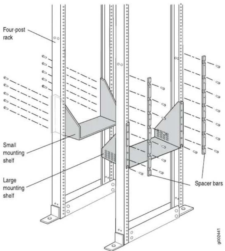
Installing the Small Shelf
To install the small shelf:
- On the back of each rear rack rail, partially insert a mounting screw into the lowest hole specified in Table 101 on page 181 for the small shelf.
- Install the small shelf on the back rack rails. Rest the bottom slot of each flange on a mounting screw. The small shelf installs on the back of the rear rails, extending toward the center of the rack. The bottom of the small shelf on the rear rack rails must align with the bottom of the large shelf on the front rack rails.
- Partially insert screws into the open holes in the flanges of the small shelf.
- Tighten all the screws completely.
Installing the Spacer Bars
The router is shipped with each spacer bar attached to the rear of each front-mounting flange.
To install the spacer bars:
- Remove each spacer bar by removing the screws that fasten the spacer bar to the front-mounting flange.
- Place one of the spacer bars over a flange of the large shelf. Position the notch in the rear of the spacer bar so the upper part of the bar is flush with the rack rail and the lower part is flush with the flange of the shelf (see Figure 65 on page 184).
- Insert a mounting screw into each of the nonthreaded holes in the recesses of the spacer bar to secure the spacer bar. Each hole should have a cage nut behind it.
- Repeat Steps 2 and 3 for the other spacer bar.
- Tighten all the screws completely.
Figure 65: Positioning the Spacer Bar on the Rack

Removing the Center-Mounting Brackets from the Chassis
You must remove the center-mounting brackets before installing the chassis in a four-post rack or cabinet.
To remove the center-mounting brackets (see Figure 66 on page 185):
-
Loosen the screws at the top and bottom of each bracket.
-
Remove each bracket.
Figure 66: Removing the Center-Mounting Bracket

Related Documentation
T1600 Router Description on page 3.
•Overview of Installing the T1600 Router on page 173
•T1600 Site Preparation Requirements Checklist on page 129
Installing the T1600 Mounting Hardware for an Open-Frame Rack
In an open-frame rack, center-mounting is generally preferable to front-mounting because the more even distribution of weight provides greater stability. If you center-mount the chassis, you use the center-mounting brackets attached to the chassis. If you front-mount
the chassis, you use the front-mounting flanges, and must remove the center-mounting brackets.
- Installing the Cage Nuts, If Needed on page 186
- Installing the Large Mounting Shelf on page 186
- Removing the Center-Mounting Brackets from the Chassis on page 187
- Removing the Spacer Bars on page 188
Installing the Cage Nuts, If Needed
Install cage nuts, if needed, in the mounting holes specified in Table 102 on page 186.
Table 102 on page 186 specifies the mounting holes in which you insert the mounting screws (an X indicates a mounting hole location), and cage nuts if needed. The hole distances are relative to one of the standard "U" divisions on the rack. For reference, the bottom of all mounting shelves is at 0.04 in. (0.02 U) above a "U" division.
Table 102: Open-Frame Rack Mounting Hole Locations
| Large ShelfDistan | ||
| X19.50 U34.13 in. (86.7 cm)59 | ||
| X17.50 U30.63 in. (77.8 cm)53 | ||
| X16.50 U28.88 in. (73.3 cm)50 | ||
| X14.50 U25.38 in. (64.5 cm)44 | ||
| 23.63 in. (60.0 cm)41 | X13.50 U | |
| 35 | 20.13 in. (51.1 cm) | X11.50 U |
| 32 | 18.38 in. (46.7 cm) | X10.50 U |
| 31 | 17.75 in. (45.1 cm) | X10.14 U |
Installing the Large Mounting Shelf
To install the large mounting shelf (see Figure 67 on page 187) in an open-frame rack:
- On the rear of each rack rail, partially insert a mounting screw into the lowest hole specified in Table 102 on page 186 for the large shelf.
- Install the large shelf on the rack. Rest the bottom slot of each flange on a mounting screw.
- Partially insert screws into the open holes in the flanges of the large shelf.
- Tighten all the screws completely.
Figure 67: Installing the Mounting Hardware for an Open-Frame Rack

Removing the Center-Mounting Brackets from the Chassis
Before front-mounting the router in an open-frame rack, you must remove the center-mounting brackets from the chassis.
To remove the center-mounting brackets (see Figure 68 on page 188):
- Loosen the screws at the top and bottom of each bracket.
- Remove each bracket.
Figure 68: Removing the Center-Mounting Bracket

Removing the Spacer Bars
The router is shipped with each spacer bar attached to the rear of each front-mounting flange. If you are installing the chassis in an open-frame rack, removing the spacer bars is optional.
To remove the spacer bars:
- Remove the screws that fasten the spacer bar to the front-mounting flange.
- Remove the spacer bars.
Related •T1600 Router Description on page 3
Documentation
•Overview of Installing the T1600 Router on page 173
•T1600 Site Preparation Requirements Checklist on page 129
CHAPTER 17
Installing the T1600 Router into a Rac
• Overview of Installing the T1600 Router into the Rack on page 191
Overview of Installing the T1600 Router into the Rack
- Read the safety information. To avoid harm to yourself or the router as you lift it into the rack, follow the guidelines and safety procedures for working with routers.
See “T1600 Chassis Lifting Guidelines” on page 559, and “General Safety Guidelines for Juniper Networks Devices” on page 549.
- Verify that the site has been prepared for the router installation.
See "T1600 Site Preparation Requirements Checklist" on page 129.
- Because of the T1600 router's size and weight—up to 606 lb (275 kg) fully configured—we strongly recommend that you lift the router into the rack using a mechanical lift. However, if a mechanical lift is not available, you can remove components from the chassis to make it easier to install into the rack. With components removed, the chassis weighs approximately 225 lb (102 kg), and four people can lift the chassis into the rack manually.
Related •Overview of Installing a T1600 Router Using a Mechanical Lift on page 193 Documentation •Overview of Installing a T1600 Router Without a Mechanical Lift on page 201
CHAPTER 18
Installing the T1600 Router into a Rac Using a Mechanical Lift
• Overview of Installing a T1600 Router Using a Mechanical Lift on page 193
- Tools Required to Install the T1600 Router Using a Mechanical Lift on page 194
- Removing the T1600 Power Supplies on page 194
- Attaching the T1600 Installation Handle on page 195
- Mounting the T1600 Chassis Using a Mechanical Lift on page 196
- Removing the T1600 Installation Handle and Reinstalling the Power Supplies on page 198
Overview of Installing a T1600 Router Using a Mechanical Lift
Because of the T1600 router's size and weight—up to 606 lb (275 kg) depending on the configuration—we strongly recommend that you install the router using a mechanical lift.
- Verify that the mounting hardware has been installed as described in "Installing the T1600 Mounting Hardware for an Open-Frame Rack" on page 185 or "Installing the T1600 Mounting Hardware for a Four-Post Rack or Cabinet" on page 181.
- Remove the router from the shipping crate as described in "Unpacking the T1600 Router" on page 176.
- Gather the tools required to install the router. See "Tools Required to Install the T1600 Router Using a Mechanical Lift" on page 194
- Remove the power supplies. See "Removing the T1600 Power Supplies" on page 194.
- Attach the T1600 installation handle. See "Attaching the T1600 Installation Handle" on page 195.
- Mount the T1600 chassis in the rack or cabinet. See “Mounting the T1600 Chassis Using a Mechanical Lift” on page 196.
- Remove the T1600 installation handle, and reinstall the power supplies.
See "Removing the T1600 Installation Handle and Reinstalling the Power Supplies" on page 198.
Tools Required to Install the T1600 Router Using a Mechanical Lift
To install the T320 chassis using a mechanical lift, you need the following tools:
- Mechanical lift
• Phillips (+) screwdrivers, number 2
Related Documentation
T1600 Router Description on page 3.
•General Safety Guidelines for Juniper Networks Devices on page 549
•T1600 General Electrical Safety Guidelines on page 575
Removing the T1600 Power Supplies
This procedure can be used for the three-input 240-A DC power supplies, four-input 240-A DC power supplies, three-phase delta AC power supplies, or three-phase wye power supplies. To remove the power supplies, start with the upper power supply:
- Attach an electrostatic discharge (ESD) grounding strap to your bare wrist, and connect the strap to an approved site ESD grounding point. See the instructions for your site.
- For three-input 240-A DC power supplies or four-input 240-A DC power supplies, switch the circuit breakers on the power supply faceplate to the off position (O). For AC power supplies or six-input DC power supplies, switch the power switch to the standby position. We recommend this even though the power supplies are not connected to power sources.
- Loosen the captive screws on the lower corners of the power supply faceplate completely.
- Twist the ejector handles on the upper corners of the faceplate counterclockwise to unseat the power supply.
- Grasp the handle on the power supply faceplate and pull firmly to start removing the power supply. Slide it halfway out of the chassis (see Figure 69 on page 195.

CAUTION: Be prepared to support the full weight of the power supply as you remove it from the router. Each three-input 240-A DC power supply weighs approximately 25 lb (11.3 kg). Each four-input 240-A DC power supply weighs approximately 26.6 lb (12.0 kg). Each six-input DC power supplies weighs 39.7 lb (18.0 kg). Each three-phase delta and wye power supply weighs approximately 31.0 lb (14.06 kg).
- Place one hand underneath the power supply to support it and slide it completely out of the chassis.
- Repeat the procedure for the other power supply.
Figure 69: Removing a Three-Input 240-A DC Power Supply

Related Documentation
Overview of Installing a T1600 Router Using a Mechanical Lift on page 193.
•Attaching the T1600 Installation Handle on page 195
•Mounting the T1600 Chassis Using a Mechanical Lift on page 196
-Removing the T1600 Installation Handle and Reinstalling the Power Supplies on page 198
Attaching the T1600 Installation Handle
To assist you with the installation of the router, attach the installation handle over the power supply slots of the chassis. To attach the installation handle:
- Place the installation handle over the location of the lower power supply.
- Tighten the captive screws of the handle into the holes previously occupied by the captive screws of the power supply (see Figure 70 on page 196).
Figure 70: Attaching the Installation Handle

natural_image
Technical line drawing of a mechanical assembly with mounting brackets and a door, showing no text or symbols.Related Documentation
Overview of Installing a T1600 Router Using a Mechanical Lift on page 193.
•Removing the T1600 Power Supplies on page 194
•Mounting the T1600 Chassis Using a Mechanical Lift on page 196
- Removing the T1600 Installation Handle and Reinstalling the Power Supplies on page 198
Mounting the T1600 Chassis Using a Mechanical Lift
Because of the router's size and weight—up to 606 lb (275 kg) depending on configuration—we strongly recommend that you install the router using a lift.
To mount the chassis in the rack or cabinet using a lift (see Figure 71 on page 197):
-
If you are installing the router in an open-frame rack, ensure that the rack is in its permanent location and is secured to the building. Ensure that the installation site allows adequate clearance for both airflow and maintenance. For details, see "Clearance Requirements for Airflow and T1600 Hardware Maintenance" on page 135.
-
Load the router onto the lift, making sure it rests securely on the lift platform.

CAUTION: Do not lift the router using the installation handle or the handles on the sides of the chassis. Use these handles only to help position the router.
- Using the lift, position the chassis in front of the rack or cabinet, centering it in front of the mounting shelves.
-
Lift the chassis approximately 0.75 in. above the surface of the mounting shelves and position it as close as possible to the shelves.
-
Carefully slide the chassis onto the mounting shelves so that the bottom of the chassis and the mounting shelves overlap by approximately 2 inches.
- With one person pulling on the installation handle from the rear of the rack or cabinet while two people push on the front-mounting flanges, slide the chassis onto the mounting shelves until the mounting brackets or front-mounting flanges contact the rack rails or spacer bars (depending on your type of installation). The shelves ensure that the holes in the mounting brackets and the front-mounting flanges of the chassis align with the holes in the rack rails.
- Move the lift away from the rack.
- If you are installing the router in a four-post rack or cabinet, install a mounting screw and a cage nut into each of the holes aligned with the threaded holes in the spacer bars. If you are installing the router in an open-frame rack, install a mounting screw into each of the open mounting holes aligned with the rack, starting from the bottom.
- Visually inspect the alignment of the router. If the router is installed properly in the rack, all the mounting screws on one side of the rack should be aligned with the mounting screws on the opposite side and the router should be level.
Figure 71: Installing the Router in a Four-Post Rack


NOTE: This illustration depicts the router being installed in a four-post rack.
Related Documentation
Overview of Installing a T1600 Router Using a Mechanical Lift on page 193.
•Removing the T1600 Power Supplies on page 194
•Attaching the T1600 Installation Handle on page 195
•T1600 Chassis Lifting Guidelines on page 559
- Removing the T1600 Installation Handle and Reinstalling the Power Supplies on page 198
Removing the T1600 Installation Handle and Reinstalling the Power Supplies
After you have installed the router, remove the installation handle and reinstall the two power supplies in the chassis by following this procedure, starting with the lower power supply (see Figure 72 on page 199):
- Attach an electrostatic discharge (ESD) grounding strap to your bare wrist, and connect the strap to an approved site ESD grounding point. See the instructions for your site.
- Loosen the captive screws on the installation handle completely, and remove the handle from the chassis.
- For three-input 240-A DC power supplies or four-input 240-A DC power supplies, switch the circuit breakers on the power supply faceplate to the off position (O). For the AC power supplies or six-input DC power supplies, switch the power switch on the power supply to the standby position.
- Using both hands, slide the power supply into the chassis until you feel resistance.
- Twist the ejector handles at the upper corners of the power supply faceplate clockwise until they stop.
- Tighten the captive screws at the lower corners of the power supply faceplate to secure the power supply in the chassis.
- Repeat the procedure for the upper power supply.
Figure 72: Reinstalling a Three-Input 240-A DC Power Supply

Figure 73: Reinstalling a Four-Input 240-A DC Power Supply

Related Documentation
•Overview of Installing a T1600 Router Using a Mechanical Lift on page 193
•Removing the T1600 Power Supplies on page 194
•Attaching the T1600 Installation Handle on page 195
•Mounting the T1600 Chassis Using a Mechanical Lift on page 196
CHAPTER 19
Installing the T1600 Router into a Rac Without a Mechanical Lift
• Overview of Installing a T1600 Router Without a Mechanical Lift on page 201
- Tools and Parts Required to Install the T1600 Router Without a Mechanical Lift on page 202
- Removing Components from the T1600 Chassis on page 202
- Installing the T1600 Chassis in the Rack Manually on page 213
- Reinstalling the T1600 Components in the Chassis on page 216
Overview of Installing a T1600 Router Without a Mechanical Lift
If you cannot use a mechanical lift to install the T1600 router (the preferred method), you can install it manually.
To install the T1600 router without a mechanical lift:
- Read the safety information. To avoid harm to yourself or the router as you install and maintain it, follow the guidelines for working with and near electrical equipment, as well as the safety procedures for working with routers. However, providing an exhaustive set of guidelines for working with electrical equipment is beyond the scope of this documentation.
See "General Safety Guidelines for Juniper Networks Devices" on page 549, "T1600
General Electrical Safety Guidelines" on page 575, and "T1600 Chassis Lifting Guidelines" on page 559
- Verify that the site has been prepared for the router installation.
See "T1600 Site Preparation Requirements Checklist" on page 129.
-
Verify that the mounting hardware has been installed as described in "Installing the T1600 Mounting Hardware for an Open-Frame Rack" on page 185 or "Installing the T1600 Mounting Hardware for a Four-Post Rack or Cabinet" on page 181.
-
Remove the router from the shipping crate as described in "Unpacking the T1600 Router" on page 176.
-
Gather the tools required to install the router.
See “Tools and Parts Required to Install the T1600 Router Without a Mechanical Lift” on page 202.
- Remove components from the chassis to make it easier to install into the rack or chassis.
See "Removing Components from the T1600 Chassis" on page 202.
- Install the T1600 Chassis in the rack manually. At least four people are needed to safely lift the chassis into the rack or cabinet. With components removed, the chassis weighs approximately 225 lb (102 kg).
See "Installing the T1600 Chassis in the Rack Manually" on page 213.
- Reinstall the components removed from the chassis.
See "Reinstalling the T1600 Components in the Chassis" on page 216.
Tools and Parts Required to Install the T1600 Router Without a Mechanical Lift
To install the router, you need the following tools and parts:
• Phillips (+) screwdrivers, numbers 1 and 2
- Flat-blade (−) screwdriver, number 1
• 7/16-in. (11 mm) socket wrench
- 3/8-in. nut driver
• ESD grounding wrist strap
Related Documentation
T1600 Site Preparation Requirements Checklist on page 129.
•General Safety Guidelines for Juniper Networks Devices on page 549
•T1600 General Electrical Safety Guidelines on page 575
Removing Components from the T1600 Chassis
To make the router light enough to install manually, you first remove most components from the chassis. These procedures for removing components from the chassis are for initial installation only, and assume that you have not connected power cables to the router. The following procedures describe how to remove components from the chassis, first from the rear and then from the front:
- Removing the T1600 DC Power Supplies on page 203
- Removing the T1600 AC Power Supplies on page 204
- Removing the T1600 SIBs on page 206
- Removing the T1600 Control Boards on page 207
- Removing the T1600 SCGs on page 207
-
Removing the T1600 Standard or Quiet Rear Fan Tray on page 208
-
Removing the T1600 Front Cable Management System on page 209
- Removing the T1600 Standard or Quiet Front Fan Trays on page 210
- Removing the T1600 FPCs on page 212
Removing the T1600 DC Power Supplies
The power supplies are located at the rear of the chassis below the SIBs. Each three-input 240-A DC power supply weighs approximately 25 lb (11.3 kg). Each four-input 240-A DC power supply weighs approximately 26.6 lb (12.0 kg). Each six-input DC power supply weights approximately 39.7 lb (18.0 kg).
To remove the power supplies, starting with the upper power supply:
- Attach an electrostatic discharge (ESD) grounding strap to your bare wrist, and connect the strap to an approved site ESD grounding point. See the instructions for your site.
- For three-input 240-A DC power supplies or four-input 240-A DC power supplies, switch the circuit breakers on the power supply faceplate to the off position (O). For six-input DC power supplies, switch the power switch on the power supply to the standby position. We recommend this even though the power supplies are not connected to power sources.
- Loosen the captive screws on the lower corners of the power supply faceplate completely.
- Twist the ejector handles on the upper corners of the faceplate counterclockwise to unseat the power supply.
- Grasp the handle on the power supply faceplate and pull firmly to start removing the power supply. Slide it halfway out of the chassis (see Figure 74 on page 204).
- Place one hand underneath the power supply to support it and slide it completely out of the chassis.

CAUTION: Be prepared to support the full weight of the power supply as you remove it from the router.
- Repeat the procedure for the other power supply.
Figure 74: Removing a Three-Input 240-A DC Power Supply Before Installing the Router

Figure 75: Removing a Four-Input 240-A Power Supply Before Installing the Router

Removing the T1600 AC Power Supplies
The power supplies are located at the rear of the chassis below the SIBs. Each three-phase delta AC power supply weighs approximately 25 lb (11.3 kg). Each three-phase wye AC power supply weighs approximately 26.6 lb (12.0 kg).
To remove the AC power supplies, starting with the upper power supply:
-
Attach an electrostatic discharge (ESD) grounding strap to your bare wrist, and connect the strap to an approved site ESD grounding point. See the instructions for your site.
-
Switch the power switch on the power supply faceplate to the standby position. We recommend this even though the power supplies are not connected to power sources.
-
Loosen the captive screws on the lower corners of the power supply faceplate completely.
-
Twist the ejector handles on the upper corners of the faceplate counterclockwise to unseat the power supply.
-
Grasp the handle on the power supply faceplate and pull firmly to start removing the power supply. Slide it halfway out of the chassis (see Figure 74 on page 204).
-
Place one hand underneath the power supply to support it and slide it completely out of the chassis.

CAUTION: Be prepared to support the full weight of the power supply as you remove it from the router.
- Repeat the procedure for the other power supply.
Figure 76: Removing a Three-Phase Delta AC Power Supply Before Installing the Router

Figure 77: Removing a Three-Phase Wye AC Power Supply Before Installing the Router

Removing the T1600 SIBs
Five SIBs are installed in the router. The SIBs are located in the rear of the chassis in the slots marked SIB0 through SIB4. Each T1600-SIB weighs approximately 6.5 lb (3 kg).
Each TXP-T1600 SIB weighs approximately 10.2 lb (4.6 kg).
To remove the SIBs (see Figure 78 on page 206):
- Place an electrostatic bag or antistatic mat on a flat, stable surface.
- Attach an electrostatic discharge (ESD) grounding strap to your bare wrist, and connect the strap to an approved site ESD grounding point. See the instructions for your site.
- Loosen the captive screws (using a Phillips (+) screwdriver, number 2) on the ejector handles on each side of the SIB faceplate.
- Flip the ejector handles outward to unseat the SIB.
- Grasp both ejector handles, pull firmly, and slide the SIB about three-quarters of the way out of the chassis.
- Place one hand underneath the SIB to support it and slide it completely out of the chassis. Place it on the antistatic mat.

CAUTION: Do not stack hardware components on one another after you remove them. Place each component on an antistatic mat resting on a stable, flat surface.
- Repeat the procedure for each of the remaining SIBs.
Figure 78: Removing a SIB

natural_image
Technical line drawing of an internal server rack unit with mounting ports and ventilation slots (no text or symbols)Removing the T1600 Control Boards
The router can have one or two control boards. They are located in the upper rear of the chassis in the slots marked CBO and CB1. Each T-CB and LCC-CB weighs approximately
5 lb (2.3 kg).
To remove the control boards (see Figure 79 on page 207):
- Place an electrostatic bag or antistatic mat on a flat, stable surface.
- Attach an electrostatic discharge (ESD) grounding strap to your bare wrist, and connect the strap to an approved site ESD grounding point. See the instructions for your site.
- Loosen the captive screws on the ejector handles on both sides of the control board faceplate.
- Flip the ejector handles outward to unseat the control board.
- Grasp the ejector handles and slide the control board about halfway out of the chassis.
- Place one hand underneath the control board to support it and slide it completely out of the chassis. Place it on the antistatic mat.

CAUTION: Do not stack hardware components on one another after you remove them. Place each component on an antistatic mat resting on a stable, flat surface.
- Repeat the procedure for the second control board.
Figure 79: Removing a Control Board

natural_image
Technical line drawing of a server rack unit with internal components and mounting tabs (no text or symbols)Removing the T1600 SCGs
The router can have one or two SCGs installed. The SCGs are located in the upper rear of the chassis, above the control boards and Routing Engines. Each SCG weighs approximately 1.9 lb (0.9 kg).
To remove the SCGs (see Figure 80 on page 208):
- Place an electrostatic bag or antistatic mat on a flat, stable surface.
- Attach an electrostatic discharge (ESD) grounding strap to your bare wrist, and connect the strap to an approved site ESD grounding point. See the instructions for your site..
- Loosen the captive screws on the edges of the SCG faceplate.
- Grasp the SCG by the handle on the faceplate and slide it out of the chassis.
- Place the SCG on the antistatic mat.
- Repeat the procedure for the second SCG.
Figure 80: Removing an SCG

natural_image
Technical line drawing of a server rack unit with internal components and mounting brackets (no text or symbols)Removing the T1600 Standard or Quiet Rear Fan Tray
The rear fan tray is mounted vertically on the right side of the rear of the chassis. The standard or quiet rear fan tray weighs about 10 lb (4.5 kg).
To remove the standard rear fan tray (see Figure 81 on page 209):
- Attach an electrostatic discharge (ESD) grounding strap to your bare wrist, and connect the strap to an approved site ESD grounding point. See the instructions for your site.
- Loosen the captive screws on the top and bottom of the fan tray faceplate.
- Grasp the handles and pull the fan tray halfway out of the chassis.
- Place one hand under the fan tray to support it and pull the fan tray completely out of the chassis.
Figure 81: Removing the T1600 Rear Fan Tray

Removing the T1600 Front Cable Management System
The front cable management system is located below the FPC card cage. The cable management system weighs approximately 5 lb (2.3 kg).
To remove the front cable management system:
- Attach an electrostatic discharge (ESD) grounding strap to your bare wrist, and connect the strap to an approved site ESD grounding point. See the instructions for your site.
- Using a 3/8-in. nut driver, unscrew the nuts on the corners of the cable management system.
- Grasp the bottom of the cable management system and pull it straight out from the studs on the front of the chassis.
Removing the T1600 Standard or Quiet Front Fan Trays
The upper front fan tray is located above the FPC card cage, and the lower front fan tray is located below the air filter. Each standard front fan tray weighs about 18.6 lb (8.4 kg). Each quiet front fan tray weighs about 17.8 lb (8.1 kg).
To remove the standard front fan trays (see Figure 82 on page 211):
- Attach an electrostatic discharge (ESD) grounding strap to your bare wrist, and connect the strap to an approved site ESD grounding point. See the instructions for your site.
- Loosen the captive screws on the corners of the faceplate of one of the fan trays.
- Grasp the handles and pull the fan tray halfway out of the chassis.
- Place one hand under the fan tray to support it and pull the fan tray completely out of the chassis.
- Repeat the procedure to remove the remaining front fan tray.
To remove a quiet upper front fan tray (see Figure 83 on page 211):
- Attach an electrostatic discharge (ESD) grounding strap to your bare wrist, and connect the strap to an approved site ESD grounding point. See the instructions for your site.
- Loosen the captive screws on the corners of the fan tray faceplate.
- Grasp the handles on the faceplate, and pull the fan tray out of the chassis approximately 1 to 3 inches.
- Press the two latches located on each side of the fan tray up to release the fan tray from the chassis.
- Place one hand under the fan tray to support it and pull the fan tray completely out of the chassis.
To remove the quiet lower front fan tray (see Figure 84 on page 211):
- Attach an electrostatic discharge (ESD) grounding strap to your bare wrist, and connect the strap to an approved site ESD grounding point. See the instructions for your site.
- Loosen the captive screws on the corners of the fan tray faceplate.
- Grasp the handles, and pull the fan tray out of the chassis approximately 1 to 3 inches.
- Press the two latches located on each side of the fan tray up to release the fan tray from the chassis.
- Place one hand under the fan tray to support it and pull the fan tray completely out of the chassis.
Figure 82: Removing a Standard Front Fan Tray

natural_image
Line drawing of a server rack unit with multiple ports and a black arrow pointing to one (no text or symbols on the device itself)Figure 83: Removing the Quiet Upper Front Fan Tray
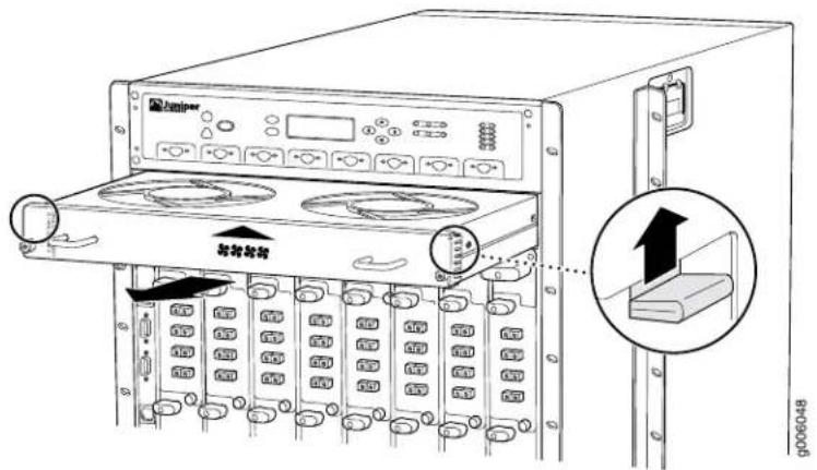
Figure 84: Removing the Quiet Lower Front Fan Tray
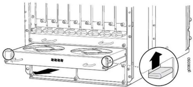
Removing the T1600 FPCs
The router holds up to eight FPCs, which are installed vertically in the front of the router. An empty FPC weighs approximately 25 lb (11.3 kg) and an FPC with PICs installed can weigh up to 37 lb (14.5 kg).
Each FPC slot not occupied by an FPC must be covered by an FPC blank panel. An FPC blank panel weighs 7 lb (3 kg).
To remove an FPC (see Figure 85 on page 213):
- Place an electrostatic bag or antistatic mat on a flat, stable surface.
- Attach an electrostatic discharge (ESD) grounding strap to your bare wrist, and connect the strap to an approved site ESD grounding point. See the instructions for your site.
- Before removing the FPCs, record their location in the chassis so that you can reinstall each FPC in the correct slot.
- If you are removing a Type 2 FPC or Type 3 FPC, loosen the screws inside the ejector handles at the top and bottom of the FPC faceplate.
- Simultaneously turn both the ejector handles counterclockwise to unseat the FPC.
- Grasp the handles and slide the FPC straight out of the card cage halfway.
- Place one hand around the front of the FPC (the PIC housing) and the other hand under it to support it. Slide the FPC completely out of the chassis, and place it on the antistatic mat or in the electrostatic bag.

CAUTION: The weight of the FPC is concentrated in the back end. Be prepared to accept the full weight—up to 37 lb (14.5 kg)—as you slide the FPC out of the chassis.
When the FPC is out of the chassis, do not hold it by the ejector handles, bus bars, or edge connectors. They cannot support its weight.
Do not stack FPCs on top of one another after removal. Place each one individually in an electrostatic bag or on its own antistatic mat on a flat, stable surface.
- Repeat the procedure for each remaining FPC.
Figure 85: Removing an FPC

natural_image
Technical line drawing of a server rack cabinet with internal compartments and ventilation slots (no text or symbols)Related Documentation
T1600 Preventing Electrostatic Discharge Damage on page 552.
•T1600 Front Cable Management System Description on page 23
•Holding T1600 FPCs on page 481
•Storing T1600 FPCs on page 485
•Maintaining the T1600 Fan Trays on page 478
Installing the T1600 Chassis in the Rack Manually
To install the router in the rack (see Figure 87 on page 216):

CAUTION: If you are installing two routers in one rack, install the lower one first. Installing a router in the upper position in a rack or cabinet requires a lift.

CAUTION: Before front-mounting the router in a rack, have a qualified technician verify that the rack is strong enough to support the router's weight and is adequately supported at the installation site.

CAUTION: Lifting the chassis and mounting it in a rack requires four people. The empty chassis weighs approximately 225 lb (102 kg).
- If you are installing the router in an open-frame rack, ensure that the rack is in its permanent location and is secured to the building.
- Ensure that the installation site allows adequate clearance for both airflow and maintenance. For details, see "Clearance Requirements for Airflow and T1600 Hardware Maintenance" on page 135.
- Attach the installation handle by tightening the captive screws of the handle into the holes previously occupied by the captive screws of the power supplies (see Figure 86 on page 214). Tighten the screws, using a Phillips (+) screwdriver, number 2.
Figure 86: Attaching the Installation Handle

natural_image
Technical line drawing of a mechanical assembly with mounting brackets and a door, showing no text or symbols.- Position the router in front of the rack or cabinet, centering it in front of the mounting shelves. Use a pallet jack if one is available.

CAUTION: Do not lift the router using the installation handle or the handles on the sides of the chassis. Use these handles only to help position the router.
- With two people in the front and two people in the back, hold onto the bottom of the chassis and carefully lift it onto the mounting shelves.

WARNING: To prevent injury, keep your back straight and lift with your legs, not your back. Avoid twisting your body as you lift. Balance the load evenly and be sure that your footing is solid.
- With one person pulling on the installation handle from the rear of the rack or cabinet while two people push on the front-mounting flanges, slide the router onto the mounting shelves until the mounting brackets or front-mounting flanges contact the rack rails or spacer bars (depending on your type of installation). The shelves ensure that the holes in the mounting brackets and the front-mounting flanges of the chassis align with the holes in the rack rails.
- If you are installing the router in a four-post rack or cabinet, install a mounting screw and a cage nut into each of the holes aligned with the threaded holes in the spacer bars. If you are installing the router in an open-frame rack, install a mounting screw into each of the open mounting holes aligned with the rack, starting from the bottom.
- Loosen the captive screws on the installation handle completely, and remove the handle from the chassis.
- Visually inspect the alignment of the router. If the router is installed properly in the rack, all the mounting screws on one side of the rack should be aligned with the mounting screws on the opposite side and the router should be level.
Figure 87: Installing the Router in the Rack


NOTE: This illustration depicts the router being installed in a four-post rack. For an illustration of an open-frame rack, see "Installing the T1600 Mounting Hardware for an Open-Frame Rack" on page 185.
Related Documentation
Overview of Installing the T1600 Router on page 173.
•Overview of Installing a T1600 Router Without a Mechanical Lift on page 201
•T1600 Chassis Lifting Guidelines on page 559
•Reinstalling the T1600 Components in the Chassis on page 216
Reinstalling the T1600 Components in the Chassis
- Reinstalling the T1600 Standard or Quiet Rear Fan Tray on page 217
- Reinstalling the T1600 SCGs on page 218
- Reinstalling the T1600 Control Boards on page 218
- Reinstalling the T1600 SIBs on page 219
-
Reinstalling the T1600 Power Supplies on page 220
-
Reinstalling the T1600 FPCs on page 222
- Reinstalling T1600 Standard Front Fan Trays on page 223
- Reinstalling T1600 Quiet Fan Trays on page 224
- Reinstalling the T1600 Front Cable Management System on page 225
Reinstalling the T1600 Standard or Quiet Rear Fan Tray
To reinstall the standard or quiet rear fan tray (see Figure 88 on page 217):
- Attach an electrostatic discharge (ESD) grounding strap to your bare wrist, and connect the strap to an approved site ESD grounding point. See the instructions for your site.
- Grasp the fan tray by its handles and insert it straight into the chassis.
- Tighten the captive screws on the top and bottom of the fan tray faceplate to secure it in the chassis.
Figure 88: Reinstalling the Rear Fan Tray
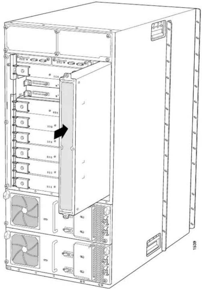
Reinstalling the T1600 SCGs
To reinstall the SCGs (see Figure 89 on page 218):
- Attach an electrostatic discharge (ESD) grounding strap to your bare wrist, and connect the strap to an approved site ESD grounding point. See the instructions for your site.
- Carefully align the sides of the SCG with the guides in the SCG slot.
- Grasp the SCG by its handle and slide it straight into the chassis until it contacts the midplane.
- Tighten the captive screws on the corners of the SCG faceplate.
- Repeat the procedure to reinstall the remaining SCG.
Figure 89: Reinstalling an SCG
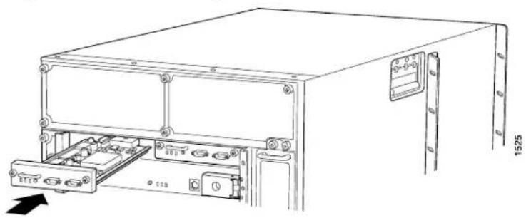
natural_image
Technical line drawing of a server rack unit with internal components and mounting bracket (no text or symbols)Reinstalling the T1600 Control Boards
To reinstall the control boards (see Figure 90 on page 219 and Figure 91 on page 219):
- Attach an electrostatic discharge (ESD) grounding strap to your bare wrist, and connect the strap to an approved site ESD grounding point. See the instructions for your site.
- Carefully align the sides of the control boards with the guides inside the chassis.
- Slide the control boards into the chassis, carefully ensuring that it is correctly aligned.
- Grasp both ejector handles and press them inward to seat the control board.
- Tighten the captive screws on the ejector handles, using a Phillips (+) screwdriver, number 2.
- Repeat the procedure to reinstall the remaining control board.
Figure 90: Reinstalling a T-CB

natural_image
Technical line drawing of an electronic device chassis with mounting brackets and internal components (no text or symbols)Figure 91: Reinstalling an LCC-CB
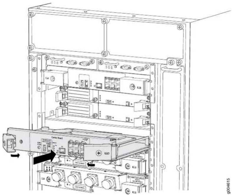
natural_image
Technical line drawing of an internal server rack with ports and connectors, showing no text or symbolsReinstalling the T1600 SIBs
To reinstall the SIBs (see Figure 92 on page 220):
- Attach an electrostatic discharge (ESD) grounding strap to your bare wrist, and connect the strap to an approved site ESD grounding point. See the instructions for your site.
- Place one hand underneath the SIB to support it. With the other hand, hold one of the ejector handles on the SIB faceplate.
- Carefully align the sides of the SIB with the guides inside the chassis.
- Slide the SIB into the chassis, carefully ensuring that it is correctly aligned.
-
Grasp both ejector handles and press them inward to seat the SIB.
-
Tighten the captive screws on the ejector handles.
- Repeat the procedure for each of the remaining SIBs.
Figure 92: Reinstalling a T1600-SIB

natural_image
Technical line drawing of an internal server rack unit with mounting ports and indicator lights (no text or symbols)Reinstalling the T1600 Power Supplies
- Reinstalling the T1600 DC Power Supplies on page 220
- Reinstalling the T1600 AC Power Supplies on page 221
Reinstalling the T1600 DC Power Supplies
You can use this procedure to reinstall three-input 240-A DC power supplies, four-input 240-A DC power supplies, or six-input DC power supplies. Reinstall the lower power supply first, then the upper power supply. To reinstall the DC power supplies (see
- Attach an electrostatic discharge (ESD) grounding strap to your bare wrist, and connect the strap to an approved site ESD grounding point. See the instructions for your site.
- For three-input 240-A DC power supplies or four-input 240-A DC power supplies, switch the circuit breakers on the power supply faceplate to the OFF position (O). For six-input DC power supplies, switch the power switch to the standby position.
- Using both hands, slide the power supply into the chassis until you feel resistance.
- Twist the ejector handles at the upper corners of the power supply faceplate clockwise until they stop.
- Tighten the captive screws at the lower corners of the power supply faceplate to secure the power supply in the chassis.
- Repeat the procedure for the upper power supply.
Figure 93: Reinstalling a Three-Input 240-A DC Power Supply

Figure 94: Reinstalling a T1600 Four-Input 240-A DC Power Supply
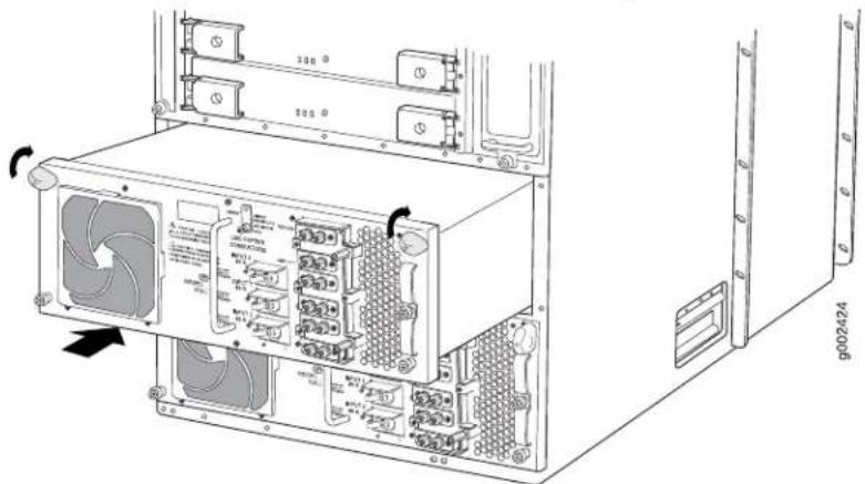
Reinstalling the T1600 AC Power Supplies
You can use this procedure to reinstall either the three-phase delta or wye AC power supplies. Reinstall the lower power supply first, then the upper power supply. To reinstall the AC power supplies (see Figure 93 on page 221):
- Attach an electrostatic discharge (ESD) grounding strap to your bare wrist, and connect the strap to an approved site ESD grounding point. See the instructions for your site.
- Switch the power switch on the power supply faceplate to the standby position.
- Using both hands, slide the power supply into the chassis until you feel resistance.
- Twist the ejector handles at the upper corners of the power supply faceplate clockwise until they stop.
- Tighten the captive screws at the lower corners of the power supply faceplate to secure the power supply in the chassis.
- Repeat the procedure for the upper power supply.
Reinstalling the T1600 FPCs
To reinstall FPCs (see Figure 95 on page 223):
- Attach an electrostatic discharge (ESD) grounding strap to your bare wrist, and connect the strap to an approved site ESD grounding point. See the instructions for your site.
- Using the list you created when you removed the FPCs, locate the slot in the FPC card cage in which you plan to install the FPC.
- Lift the FPC into place and carefully align first the bottom, then the top of the FPC with the guides inside the card cage. Be sure the FPC is right-side up, with the components on the right of the FPC.

CAUTION: When the FPC is out of the chassis, do not hold it by the ejector handles, bus bars, or edge connectors. They cannot support its weight.
- Slide the FPC all the way into the card cage until you feel resistance.
- Starting with the ejector handles on the FPC faceplate nearly horizontal, simultaneously turn both ejector handles clockwise to seat the FPC.
- If you are installing a Type 2 FPC or Type 3 FPC, tighten the screws inside the ejector handles to secure the FPC. Do not overtighten them.
- Repeat the procedure to reinstall each remaining FPC.
Figure 95: Reinstalling an FPC
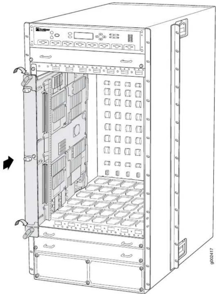
natural_image
Technical line drawing of a server rack unit with multiple drive bays and ventilation slots (no text or labels)Reinstalling T1600 Standard Front Fan Trays
To reinstall the standard front fan trays (see Figure 96 on page 224):
- Attach an electrostatic discharge (ESD) grounding strap to your bare wrist, and connect the strap to an approved site ESD grounding point. See the instructions for your site.
- Grasp one of the fan trays by its handles and insert it straight into the chassis.
- Tighten the captive screw on each side of the fan tray faceplate to secure it in the chassis.
- Repeat the procedure to reinstall the remaining fan tray.
Figure 96: Reinstalling a Front Fan Tray

natural_image
Line drawing of a rack-mounted server unit with multiple drive bays and a black arrow pointing to a component (no text or symbols)Reinstalling T1600 Quiet Fan Trays
To reinstall the quiet front fan trays:
- Attach an electrostatic discharge (ESD) grounding strap to your bare wrist, and connect the strap to an approved site ESD grounding point. See the instructions for your site.
- Locate the fan tray labeled FAN-T-FTOP-S UPPER FANTRAY.
- Press the two latches located on each side of the fan tray up, and insert the upper front fan tray straight into the upper fan tray slot (see Figure 97 on page 225).
- Tighten the captive screws on each side of the fan tray faceplate to secure it in the chassis.
- Locate a replacement quiet lower fan tray labeled FAN-T-FBOT-S LOWER FANTRAY.
- Press the two latches located on each side of the fan tray up, and insert the lower fan tray straight into the lower fan tray slot (see Figure 98 on page 225).
- Tighten the captive screws on each side of the quiet lower front fan tray faceplate to secure it in the chassis.
- Unlock the front cable management system and lower it to the fully lowered position.
Figure 97: Reinstalling the Upper Front Quiet Fan Tray
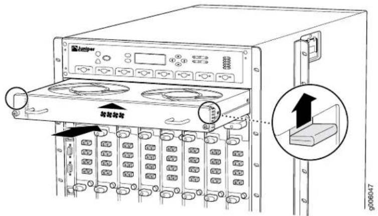
Figure 98: Reinstalling the Lower Front Quiet Fan Tray

Reinstalling the T1600 Front Cable Management System
To reinstall the front cable management system:
- Position the front cable management system on the studs on the lower front of the chassis.
- Insert the nuts through the holes in the cable management system onto the studs on the chassis.
- Using a 3/8-in. nut driver, tighten the nuts securely.
Related Documentation
•Overview of Installing the T1600 Router on page 173
•Overview of Installing a T1600 Router Without a Mechanical Lift on page 201
•Removing Components from the T1600 Chassis on page 202
•T1600 Preventing Electrostatic Discharge Damage on page 552
CHAPTER 20
Connecting the T1600 Router to Groun
- Tools and Parts Required to Ground the T1600 Router on page 227
- Connecting the T1600 Grounding Cable on page 228
Tools and Parts Required to Ground the T1600 Router
- Grounding cable (which you must provide)
- Grounding lug (provided with the router)
Figure 99: Grounding Lug
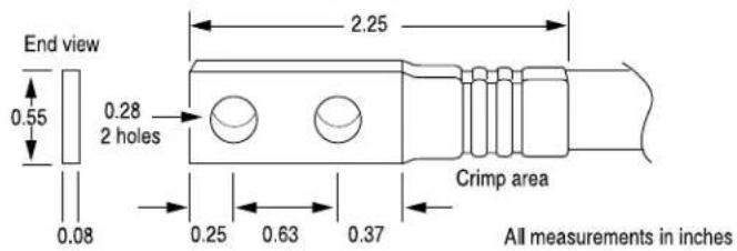
9002137
• M6 screws or UNC 1/4-20 screws
• Electrostatic discharge (ESD) grounding wrist strap
Related Documentation
T1600 Chassis Description on page 19.
•T1600 Chassis Grounding Cable and Lug Specifications on page 132
•T1600 Preventing Electrostatic Discharge Damage on page 552
Connecting the T1600 Grounding Cable
You ground the router by connecting a grounding cable to earth ground and then attaching it to the chassis grounding points with two screws. You must provide the grounding cable (a cable lug is supplied with the router). To connect the grounding cable (see
- Attach an electrostatic discharge (ESD) grounding strap to your bare wrist, and connect the strap to an approved site ESD grounding point. See the instructions for your site.
- Make sure that grounding surfaces are clean and brought to a bright finish before grounding connections are made.
- Connect the grounding cable to a proper earth ground.
- Verify that a licensed electrician has attached the cable lug provided with the router to the grounding cable.
- Attach an electrostatic discharge (ESD) grounding strap to your bare wrist, and connect the strap to one of the ESD points on the chassis.
- Place the grounding cable lug over the grounding points. The left pair is sized for M6 screws, and the right pair is sized for UNC 1/4-20 screws.
- Secure the grounding cable lug to the grounding points, first with the washers, then with the screws.
- Verify that the grounding cabling is correct, that the grounding cable does not touch or block access to router components, and that it does not drape where people could trip on it.
Figure 100: Connecting the Grounding Cable

Related Documentation
•T1600 Chassis Description on page 19
•Tools and Parts Required to Ground the T1600 Router on page 227
•T1600 Chassis Grounding Cable and Lug Specifications on page 132
•T1600 Preventing Electrostatic Discharge Damage on page 552
CHAPTER 21
Connecting the T1600 Router to Extern Devices
• Overview of Connecting the T1600 Router to External Devices on page 231
- Tools and Parts Required to Connect the T1600 Router to External Devices on page 232
- Connecting the T1600 Router to a Management Console or Auxiliary Device on page 232
- Connecting the T1600 Router to a Network for Out-of-Band Management on page 234
- Connecting the T1600 Router to an External Alarm-Reporting Device on page 235
- Connecting PIC Cables to the T1600 Router on page 236
Overview of Connecting the T1600 Router to External Devices
After you have grounded the T1600 Core Router, you can connect the following external devices:
- An external console or auxiliary device to the CONSOLE ports on the Connector Interface Panel (CIP).
See "Connecting the T1600 Router to a Management Console or Auxiliary Device" on page 232
- A laptop, modem, or other auxiliary device to the AUXILIARY ports on the CIP.
See “Connecting the T1600 Router to a Management Console or Auxiliary Device” on page 232.
- A management network to the ETHERNET ports on the CIP.
See “Connecting the T1600 Router to a Network for Out-of-Band Management” on page 234.
- An external alarm-reporting device to the alarm relay contacts on the CIP.
See "Connecting the T1600 Router to an External Alarm-Reporting Device" on page 235.
- An external clocking device to the EXTERNAL CLOCK INPUTS on the SONET clock generator with RJ-48 ports.
See Connecting the T1600 Router to an External Clocking Device.

NOTE: The external clock inputs on the SCG with DB-9 ports are not supported.
- A network connection to the ports on the PICs.
See “Connecting PIC Cables to the T1600 Router” on page 236.
Related Documentation
Tools and Parts Required to Connect the T1600 Router to External Devices on page 232.
Tools and Parts Required to Connect the T1600 Router to External Devices
To connect the router to management devices and PICs, you need the following tools and parts:
• Phillips (+) screwdrivers, numbers 1 and 2
• 2.5-mm flat-blade (-) screwdriver
- Wire cutters
• Electrostatic discharge (ESD) grounding wrist strap
Related Documentation
- Connecting DC Power to the T1600 Router (Three-Input 240-A DC Power Supplies or Four-Input 240-A DC Power Supplies) on page 240
- Connecting DC Power to the T1600 Router (Six 60-A Inputs to Six-Input DC Power Supplies) on page 243
- Connecting DC Power to the T1600 Router (Five 60-A Inputs to Six-Input DC Power Supplies) on page 247
•Powering Off the T1600 Router on page 258
•T1600 Preventing Electrostatic Discharge Damage on page 552
Connecting the T1600 Router to a Management Console or Auxiliary Device
To use a system console to configure and manage the Routing Engine, connect it to the appropriate CONSOLE port on the CIP. To use a laptop, modem, or other auxiliary device, connect it to the appropriate AUXILIARY port on the CIP. Both ports accept an RS-232 (EIA-232) serial cable with a DB-9 female connector. One DB-9/DB-9 cable is provided with the router. To connect a device to the CONSOLE port, and another device to the AUXILIARY port, you must supply another cable.
To connect a management console or auxiliary device:
- Turn off the power to the console or auxiliary device.
-
Attach an electrostatic discharge (ESD) grounding strap to your bare wrist, and connect the strap to one of the ESD points on the chassis.
-
Connect one end (shown in Figure 101 on page 233) of a serial cable with a DB-9 female connector to the appropriate CONSOLE or AUXILIARY port (see Figure 102 on page 233). The ports labeled HOST 0 connect to the Routing Engine in the upper Routing Engine slot (RE0), and the ports labeled HOST 1 connect to the Routing Engine in the lower Routing Engine slot (RE1).

NOTE:
For console devices, configure the serial port to the following values:
- Baud rate—9600
- Parity-N
- Data bits—8
- Stop bits—1
-
Flow control—none
-
Using a 2.5-mm flat-blade screwdriver, tighten the screws on the connector.
- Attach the other end of the cable to the console or auxiliary device.
Figure 101: Console and Auxiliary Serial Port Connector

natural_image
Line drawing of a V1222 VGA connector with 7 pins (no text or symbols)Figure 102: Console and Auxiliary Ports on the CIP
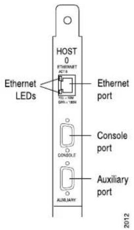
Related Documentation
T1600 Routing Engine Interface Cable and Wire Specifications on page 167.
•Overview of Connecting the T1600 Router to External Devices on page 231
•T1600 Preventing Electrostatic Discharge Damage on page 552
Connecting the T1600 Router to a Network for Out-of-Band Management
To connect the Routing Engine to a network for out-of-band management, connect an Ethernet with RJ-45 connectors to the ETHERNET port on the CIP. One cable is provided with the router.
- Attach an electrostatic discharge (ESD) grounding strap to your bare wrist, and connect the strap to one of the ESD points on the chassis.
- Turn off the power to the management device.
- Plug one end of the Ethernet cable (Figure 103 on page 234 shows the connector) in to the appropriate ETHERNET port on the CIP (see Figure 104 on page 235). The ports labeled HOST 0 connect to the Routing Engine in the upper Routing Engine slot (RE0), and the ports labeled HOST 1 connect to the Routing Engine in the lower Routing Engine slot (RE1).
- Plug the other end of the cable into the network device.
Figure 103: Routing Engine Ethernet Cable Connector
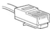
g001063
Figure 104: ETHERNET Port on the CIP

Related Documentation
T1600 Routing Engine Interface Cable and Wire Specifications on page 167.
•Overview of Connecting the T1600 Router to External Devices on page 231
•T1600 Preventing Electrostatic Discharge Damage on page 552
Connecting the T1600 Router to an External Alarm-Reporting Device
To connect the router to external alarm-reporting devices, attach wires to the RED ALARM and YELLOW ALARM relay contacts on the CIP. A system condition that triggers the red or yellow alarm LED on the craft interface also activates the corresponding alarm relay contact.
The terminal blocks that plug into the alarm relay contacts are supplied with the router. They accept wire of any gauge between 28-AWG and 14-AWG (0.08 and 2.08 mm which is not provided. Use the gauge of wire appropriate for the external device you are connecting.
To connect an external device to an alarm relay contact:
- Prepare the required length of wire with gauge between 28-AWG and 14-AWG (0.08 and 2.08 mm).
- Attach an electrostatic discharge (ESD) grounding strap to your bare wrist, and connect the strap to one of the ESD points on the chassis.
- While the terminal block is not plugged into the relay contact, use a 2.5-mm flat-blade screwdriver to loosen the small screws on its side. With the small screws on its side facing left, insert wires into the slots in the front of the block based on the wiring for the external device. Tighten the screws to secure the wire.
- Orient the terminal block according to the labels to the left of the appropriate relay contact (NC means "normally closed, C means "common," and (NO means "normally open").
- Plug the terminal block into the relay contact and use a 2.5-mm flat-blade screwdriver to tighten the screws on the face of the block.
- Attach the other end of the wires to the external device.
If attaching a reporting device for the other kind of alarm, repeat the procedure.
Related Documentation
Overview of Connecting the T1600 Router to External Devices on page 231.
•T1600 Preventing Electrostatic Discharge Damage on page 552
•Replacing the T1600 Alarm Relay Wires on page 310
Connecting PIC Cables to the T1600 Router
The router supports PICs that use various kinds of network cable, including multimode and single-mode fiber-optic cable. For information about the type of cable used by each PIC, see the interface module reference for your device.
You connect PICs to the network by plugging in network cable. To connect cable to the PICs (see Figure 105 on page 237, which shows a fiber-optic PIC):
-
Have ready a length of the type of cable used by the PIC. For cable specifications, see "Supported Network Interface Standards by Transceiver for the ACX, M, MX, and T Series" on page 155 in the interface module reference for your device.
-
If the PIC cable connector port is covered by a rubber safety plug, remove the plug.

WARNING: Do not look directly into a fiber-optic transceiver or into the ends of fiber-optic cables. Fiber-optic transceivers and fiber-optic cable connected to a transceiver emit laser light that can damage your eyes.

CAUTION: Do not leave a fiber-optic transceiver uncovered except when inserting or removing cable. The safety cap keeps the port clean and prevents accidental exposure to laser light.
-
Insert the cable connector into the cable connector port on the PIC faceplate.
-
Arrange the cable in the cable management system to prevent it from dislodging or developing stress points. Secure the cable so that it is not supporting its own weight as it hangs to the floor. Place excess cable out of the way in a neatly coiled loop in the cable management system. Placing fasteners on the loop helps to maintain its shape.

CAUTION: Avoid bending fiber-optic cable beyond its minimum bend radius. An arc smaller than a few inches in diameter can damage the cable and cause problems that are difficult to diagnose.

CAUTION: Do not let fiber-optic cable hang free from the connector. Do not allow fastened loops of cable to dangle, which stresses the cable at the fastening point.
Figure 105: Attaching a Cable to a PIC
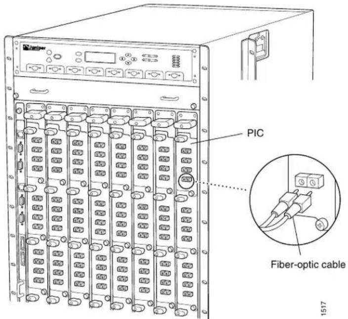
Related Documentation
•T1600 Preventing Electrostatic Discharge Damage on page 552
•Installing a T1600 PIC Cable on page 390
- Maintaining T1600 PICs and PIC Cables on page 488
•Replacing a T1600 PIC Cable on page 389
CHAPTER 22
Providing Power to the T1600 Router
- Tools and Parts Required to Provide Power to the T1600 Router on page 239
- Connecting DC Power to the T1600 Router (Three-Input 240-A DC Power Supplies or Four-Input 240-A DC Power Supplies) on page 240
- Connecting DC Power to the T1600 Router (Six 60-A Inputs to Six-Input DC Power Supplies) on page 243
- Connecting DC Power to the T1600 Router (Five 60-A Inputs to Six-Input DC Power Supplies) on page 247
• Powering On the DC-Powered T1600 Router on page 251 - Connecting AC Power to a T1600 Router with Three-Phase Delta AC Power Supplies on page 253
- Connecting AC Power to a T1600 Router with Three-Phase Wye AC Power Supplies on page 255
• Powering On the AC-Powered T1600 Router on page 257
• Powering Off the T1600 Router on page 258
Tools and Parts Required to Provide Power to the T1600 Router
- DC-powered routers: 7/16-in. (11 mm) hexagonal-head external drive nut driver, with a torque range between 23 lb-in. (2.6 Nm) and 25 lb-in. (2.8 Nm), for tightening nuts to terminal studs on each power supply on a DC-powered router.

CAUTION: You must use an appropriate torque-controlled tool to tighten the nuts. Applying excessive torque damages the terminal studs and the power supply. The absolute maximum torque that may be applied to this nut is 45 lb-in. (5.0 Nm).
- AC-powered router:
• Phillips (+) screwdriver, number 2 to access the metal AC wiring compartment
- 1/4-in. slotted screwdriver to attach the ground wire and input terminal wires of the AC power cord.
• Electrostatic discharge (ESD) grounding wrist strap
Related Documentation
T1600 Preventing Electrostatic Discharge Damage on page 552.
•T1600 General Electrical Safety Guidelines on page 575
•T1600 DC Power System Electrical Specifications on page 137
•T1600 AC Power Requirements on page 149
Connecting DC Power to the T1600 Router (Three-Input 240-A DC Power Supplies or Four-Input 240-A DC Power Supplies)
You connect DC power to the router by attaching power cables from the DC power sources to the terminal studs on the power supply faceplates. You must provide power cables (the cable lugs are supplied with the router).

CAUTION: All inputs on the DC power supply in slot PEM0 must be powered by dedicated powerfeedsderivedfromfeedA, and all inputs on the DC power supply in slot PEM1 must be powered by dedicated power feeds derived from feed B. This configuration provides the commonly deployed A/B feed redundancy for the system.
To connect the DC source power cables to the router, follow this procedure for each DC power supply:
- Attach an electrostatic discharge (ESD) grounding strap to your bare wrist, and connect the strap to an approved site ESD grounding point. See the instructions for your site. Switch off the customer site circuit breakers. Ensure that the voltage across the DC power source cable leads is 0 V and that there is no chance that the cable leads might become active during installation.
- Verify that a licensed electrician has attached the cable lugs provided with the router to the power cables.
- Attach an electrostatic discharge (ESD) grounding strap to your bare wrist, and connect the strap to one of the ESD points on the chassis.
- Switch the circuit breakers on the power supply faceplate to the OFF position (O).
- Remove the clear plastic cover protecting the terminal studs on the faceplate.
- Remove the nut and washer from each power terminal stud. If no washers and nuts are already installed, they should be in the accessory box.
- Attach the lugs on the DC source power cables to the terminal studs. Secure the cable lugs to the terminal studs, first with the washers, then with the nuts. Using a 7/16-in. (11 mm) nut driver, tighten the nuts. Apply between 23 lb-in. (2.6 Nm) and 25 lb-in. (2.8 Nm) of torque to each nut.

CAUTION: You must use an appropriate torque-controlled tool to tighten the nuts. Applying excessive torque damages the terminal studs and the
power supply. The absolute maximum torque that may be applied to this nut is 45 lb-in. (5.0 Nm).
a. Attach the positive (+) DC source power cable lugs to the RTN (return) terminals.
b. Attach the negative (−) DC source power cable lugs to the -48V (input) terminals.

CAUTION: You must ensure that power connections maintain the proper polarity. The power source cables might be labeled (+) and (−) to indicate their polarity. There is no standard color coding for DC power cables. The color coding used by the external DC power source at your site determines the color coding for the leads on the power cables that attach to the terminal studs on each power supply.
- Loosen the captive screw or screws on the cable restraint on the right edge of the power supply faceplate (using a Phillips (+) screwdriver, number 2).
- Route the positive and negative DC power cables through the cable restraint.
- Tighten the cable restraint captive screw or screws to hold the power cables in place.
- Verify that the power cabling is correct, that the power cables are not touching or blocking access to router components, and that they do not drape where people could trip on them.
- Replace the clear plastic cover over the terminal studs on the faceplate.
Figure 106: Connecting Power to the Three-Input 240-A DC Power Supply

Figure 107: Connecting Power to the Four-Input 240-A DC Power Supply

Related Documentation
T1600 Power System Description on page 105.
•T1600 Three-Input 240-A DC Power Supply Description on page 106
•T1600 Four-Input 240-A DC Power Supply Description on page 109
•T1600 Preventing Electrostatic Discharge Damage on page 552
•T1600 General Electrical Safety Guidelines on page 575
•T1600 DC Power Cables and Lugs on page 144
Connecting DC Power to the T1600 Router (Six 60-A Inputs to Six-Input DC Power Supplies)
You connect DC power to the router by attaching power cables from the DC power sources to the terminal studs on the power supply faceplates. You must provide power cables (the cable lugs are supplied with the router).

CAUTION: All connected inputs on the DC power supply in slot PEM0 must be powered by dedicated powerfeeds derived from feedA, and all connected inputs on the DC power supply in slot PEM1 must be powered by dedicated power feeds derived from feed B. This configuration provides the commonly deployed A/B feed redundancy for the system.

NOTE: We recommend that the positive (+) DC source power cables for the RTN (return) terminals be 2.6 in. (6.6 cm) longer than the negative (−) DC source power cables for the -48 V (input) terminals.

CAUTION: You must use an appropriate torque-controlled tool to tighten the nuts. Applying excessive torque damages the terminal studs and the power supply. The absolute maximum torque that may be applied to this nut is 45 lb-in. (5.0 Nm).

CAUTION: You must ensure that power connections maintain the proper polarity. The power source cables might be labeled (+) and (−) to indicate their polarity. There is no standard color coding for DC power cables. The color coding used by the external DC power source at your site determines the color coding for the leads on the power cables that attach to the terminal studs on each power supply.
To connect DC source power cables to the router, follow this procedure for each DC power supply:
- Verify that a properly rated customer site circuit breaker for each DC power cable has been installed. See the DC power electrical safety guidelines for your router for more information.
- Switch off the customer site circuit breakers. Ensure that the voltage across the DC power source cable leads is 0 V and that there is no chance that the cable leads might become active during installation.
- Verify that a licensed electrician has attached appropriate cable lugs to the DC power cables. See the DC power cable and lug specifications for your router for more information.
- Switch the power switch on the power supply faceplate to the standby position.
- Remove the clear plastic cover protecting the terminal studs on the faceplate.
- Remove the nut and washer from each power terminal stud to be connected. If no washers and nuts are already installed, they should be in the accessory box.
- Remove the captive screws on all three cable restraints on the right edge of the power supply faceplate (using a Phillips (+) screwdriver, number 2).
- Route the negative (−) DC source power cables for INPUT 0, INPUT 1, INPUT 3, and INPUT 4 over the smallest cable restraint on the far right. The cable restraint is marked as follows top to bottom: INPUT 0, INPUT 1, INPUT 3, and INPUT 4.

NOTE: You must route the cables in the locations as marked to be able to replace the clear plastic cover over the terminal studs.
Attach the negative (−) DC source power cable lugs INPUT 0, INPUT 1, INPUT 3, and
INPUT 4 to the -48 V (input) terminals on the right. Secure the cable lugs to the terminal studs, first with the washers, then with the nuts. Using a 7/16-in. (11 mm) nut driver, tighten the nuts. Apply between 23 lb-in. (2.6 Nm) and 25 lb-in. (2.8 Nm) of torque to each nut.
Figure 108: Connecting DC Power Cables

Figure 109: Connecting Negative (−) DC Power Cables to INPUT 0, INPUT 1, INPUT 3, and INPUT 4

-
Replace the smallest cable restraint on the far right, and tighten the captive screw to hold the power cables for INPUT 0, INPUT 1, INPUT 3, and INPUT 4 in place.
-
Route the negative (−) DC source power cables for INPUT 2 and INPUT 5 through the middle cable restraint. The middle cable restraint is marked as follows from top to bottom: INPUT 2, RTN 2, RTN 5, and INPUT 5.

NOTE: You must route the cables in the locations as marked to be able to replace the clear plastic cover over the terminal studs.
Attach the negative (−) DC source power cable lugs to the -48 V (input) terminals on the right. Secure the cable lugs to the terminal studs, first with the washers, then with the nuts. Using a 7/16-in. (11 mm) nut driver, tighten the nuts. Apply between 23 lb-in. (2.6 Nm) and 25 lb-in. (2.8 Nm) of torque to each nut.
Figure 110: Connecting Negative (−) DC Power Cables to INPUT 2 and INPUT 5

- Route the positive (+) DC source power cables for RTN 2 and RTN 5 over the middle cable restraint. The middle cable restraint is marked as follows from top to bottom: INPUT 2, RTN 2, RTN 5, and INPUT 5.

NOTE: You must route the cables as marked to be able to replace the clear plastic cover over the terminal studs.
Attach the positive (+) DC source power cable lugs RTN 2 and RTN 5 to the RTN (return) terminals on the left. Secure the cable lugs to the terminal studs, first with the washers, then with the nuts. Using a 7/16-in. (11 mm) nut driver, tighten the nuts. Apply between 23 lb-in. (2.6 Nm) and 25 lb-in. (2.8 Nm) of torque to each nut.
-
Replace the middle cable restraint, and tighten the captive screw to hold the power cables for INPUT 2, INPUT 5, RTN 2, and RTN 5 in place.
-
Route the positive (+) DC source power cables for RTN 0, RTN 1, RTN 3, and RTN 4 over the largest cable restraint on the left. The left cable restraint is marked as follows from top to bottom: RTN 0, RTN 1, RTN 3, and RTN 4.

NOTE: You must route the cables as marked to be able to replace the clear plastic cover over the terminal studs.
Attach the positive (+) DC source power cable lugs to the RTN 0, RTN 1, RTN 3, and RTN 4 terminals on the left. Secure the cable lugs to the terminal studs, first with the washers, then with the nuts. Using a 7/16-in. (11 mm) nut driver, tighten the nuts. Apply between 23 lb-in. (2.6 Nm) and 25 lb-in. (2.8 Nm) of torque to each nut.
- Replace the left cable restraint, and tighten the captive screw to hold the power cables for RTN 0, RTN 1, RTN 3, and RTN 4 in place.
Figure 111: Connecting Positive (+) DC Power Cables to RTN 2, RTN 5, RTN 0, RTN 1, RTN 3, and RTN 4

- Verify that the power cabling is correct, that the power cables are not touching or blocking access to router components, and that they do not drape where people could trip on them.
- Replace the clear plastic cover over the terminal studs on the faceplate.
Related Documentation
Tools and Parts Required to Provide Power to the T1600 Router on page 239.
- Connecting DC Power to the T1600 Router (Five 60-A Inputs to Six-Input DC Power Supplies) on page 247
•Powering On the DC-Powered T1600 Router on page 251 - Configuring DC Power on a T1600 Router on page 266
•Troubleshooting the T1600 Power System on page 516
•T1600 Preventing Electrostatic Discharge Damage on page 552
•T1600 General Electrical Safety Guidelines on page 575
Connecting DC Power to the T1600 Router (Five 60-A Inputs to Six-Input DC Power Supplies)
You connect DC power to the router by attaching power cables from the DC power sources to the terminal studs on the power supply faceplates. You must provide power cables (the cable lugs are supplied with the router).

CAUTION: Do not use a terminal jumper for 60-A DC power cables. Using a terminal jumper is not supported for this procedure. Doing so will cause a short across the inputs and trip your external circuit breaker.

CAUTION: All connected inputs on the DC power supply in slot PEM0 must be powered by dedicated powerfeedsderivedfromfeedA, and all connected inputs on the DC power supply in slot PEM1 must be powered by dedicated
power feeds derived from feed B. This configuration provides the commonly deployed A/B feed redundancy for the system.

CAUTION: You must use an appropriate torque-controlled tool to tighten the nuts. Applying excessive torque damages the terminal studs and the power supply. The absolute maximum torque that may be applied to this nut is 45 lb-in. (5.0 Nm).

CAUTION: You must ensure that power connections maintain the proper polarity. The power source cables might be labeled (+) and (−) to indicate their polarity. There is no standard color coding for DC power cables. The color coding used by the external DC power source at your site determines the color coding for the leads on the power cables that attach to the terminal studs on each power supply.

NOTE: We recommend that the positive (+) DC source power cables to be connected to the RTN (return) terminals be 2.6 in. (6.6 cm) longer than the negative (−) DC source power cables to be connected to the -48 V (input) terminals.
To connect five 60-A DC source power cables to the router, follow this procedure for each DC power supply:
- Verify that a properly rated customer site circuit breaker for each DC power cable has been installed. See the DC power electrical safety guidelines for your router for more information.
- Switch off the customer site circuit breakers. Ensure that the voltage across the DC power source cable leads is 0 V and that there is no chance that the cable leads might become active during installation.
- Verify that a licensed electrician has attached appropriate cable lugs to the DC power cables. See the DC power cable and lug specifications for your router for more information.
- Switch the power switch on the power supply faceplate to the standby position.
- Remove the clear plastic cover protecting the terminal studs on the faceplate.
- Remove the nut and washer from each power terminal stud to be connected. If no washers and nuts are already installed, they should be in the accessory box.
-
Remove the captive screws on all three cable restraints on the right edge of the power supply faceplate (using a Phillips (+) screwdriver, number 2).
-
Route the negative (−) DC source power cables for INPUT 0, INPUT 1, INPUT 3, and INPUT 4, over the smallest cable restraint on the far right. The cable restraint is marked as follows top to bottom: INPUT 0, INPUT 1, INPUT 3, and INPUT 4,

NOTE: You must route the cables in the locations as marked to be able to replace the clear plastic cover over the terminal studs.
Attach the negative (−) DC source power cable lugs to the -48V (input) terminals on the right: INPUT 0, INPUT 1, INPUT 3, and INPUT 4. Secure the cable lugs to the terminal studs, first with the washers, then with the nuts. Using a 7/16-in. (11 mm) nut driver, tighten the nuts. Apply between 23 lb-in. (2.6 Nm) and 25 lb-in. (2.8 Nm) of torque to each nut.
Figure 112: Connecting DC Power Cables
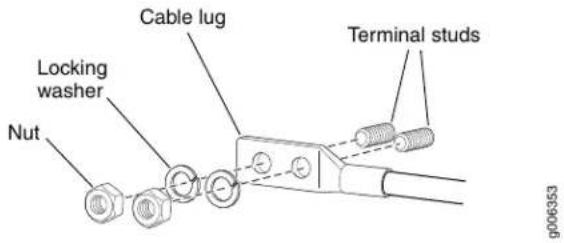
Figure 113: Connecting Negative (−) DC Power Cables to INPUT 0, INPUT 1, INPUT 3, and INPUT 4

-
Replace the smallest cable restraint on the far right, and tighten the captive screw to hold the power cables for INPUT 0, INPUT 1, INPUT 3, and INPUT 4 in place.
-
Route the negative (−) DC source power cables for INPUT 2, through the middle cable restraint. The middle cable restraint is marked as follows from top to bottom: INPUT 2, RTN 2, RTN 5, and INPUT 5.

NOTE: You must route the cable in the location as marked to be able to replace the clear plastic cover over the terminal studs.
Attach the negative (−) DC source power cable lugs to the INPUT 2 -48 V (input) terminal on the right. Secure the cable lug to the terminal studs, first with the washer,
then with the nut. Using a 7/16-in. (11 mm) nut driver, tighten the nut. Apply between 23 lb-in. (2.6 Nm) and 25 lb-in. (2.8 Nm) of torque to each nut.
Figure 114: Connecting Negative (−) DC Power Cable to INPUT 2

- Route the positive (+) DC source power cables for RTN 2 over the middle cable restraint. The middle cable restraint is marked as follows from top to bottom: INPUT 2, RTN 2, RTN 5, and INPUT 5,

NOTE: You must route the cables as marked to be able to replace the clear plastic cover over the terminal studs.
Attach the positive (+) DC source power cable lug to the RTN 2 (return) terminal on the left. Secure the cable lug to the terminal stud, first with the washer, then with the nut. Using a 7/16-in. (11 mm) nut driver, tighten the nuts. Apply between 23 lb-in. (2.6 Nm) and 25 lb-in. (2.8 Nm) of torque to the nut.
-
Replace the middle cable restraint, and tighten the captive screw to hold the power cables for INPUT 2 and RTN 2 in place.
-
Route the positive (+) DC source power cables for RTN 0, RTN 1, RTN 3, and RTN 4 over the largest cable restraint on the left. The left cable restraint is marked as follows from top to bottom RTN 0, RTN 1, RTN 3, and RTN 4,

NOTE: You must route the cables as marked to be able to replace the clear plastic cover over the terminal studs.
Attach the positive (+) DC source power cable lugs to the RTN terminals on the left: RTN 0, RTN 1, RTN 3, and RTN 4. Secure the cable lugs to the terminal studs, first with the washers, then with the nuts. Using a 7/16-in. (11 mm) nut driver, tighten the nuts. Apply between 23 lb-in. (2.6 Nm) and 25 lb-in. (2.8 Nm) of torque to each nut.
- Replace the left cable restraint, and tighten the captive screw to hold the power cables for RTN 0, RTN 1, RTN 3, and RTN 4 in place.
Figure 115: Connecting Positive (+) DC Power Cable to RTN 2, RTN 0, RTN 1, RTN 3, RTN 4

- Verify that the power cabling is correct, that the power cables are not touching or blocking access to router components, and that they do not drape where people could trip on them.
- Replace the clear plastic cover over the terminal studs on the faceplate.
Related Documentation
Tools and Parts Required to Provide Power to the T1600 Router on page 239.
- Connecting DC Power to the T1600 Router (Six 60-A Inputs to Six-Input DC Power Supplies) on page 243
•Powering On the DC-Powered T1600 Router on page 251 - Configuring DC Power on a T1600 Router on page 266
•Troubleshooting the T1600 Power System on page 516
•T1600 Preventing Electrostatic Discharge Damage on page 552
•T1600 General Electrical Safety Guidelines on page 575
Powering On the DC-Powered T1600 Router
You can use this procedure for a T1600 router with three-input 240-A DC power supplies, four-input 240-A DC power supplies, or six-input DC power supplies.
To power on the DC-powered router:
- Verify that the power supplies are fully inserted in the chassis and that the captive screws on their faceplates are tightened.
- Verify that the source power cables are connected to the appropriate terminal: the positive (+) source cable to the return terminal (labeled RTN) and the negative (−) source cable to the input terminal (labeled -48V).
- Verify that an external management device is connected to one of the Routing Engine ports on the CIP (AUXILIARY, CONSOLE, or ETHERNET).

NOTE: If you are powering on the router for the first time, the ETHERNET port does not function until after the initial configuration procedure.
- Turn on the power to the external management device.
- Switch on the dedicated customer site circuit breakers to provide power to the DC power cables. Follow your site's procedures.
- Verify that the INPUT PRESENT LED for each input on the DC power supply faceplate is lit steadily green, indicating that the inputs are receiving power.
- For three-input 240-A DC power supplies and four-input 240-A DC power supplies, switch the circuit breakers on one of the power supplies to the ON position (I).

NOTE: If the router is completely powered off when you power on the power supply, the Routing Engine boots as the power supply completes its startup sequence. If the Routing Engine finishes booting and you need topower offthe router again, see the procedure for poweringoff the router. After powering on a power supply, wait at least 60 seconds before turning it off.
For six-input power supplies, switch the power switch on one of the power supplies to the ON position (—). The DC OK LED blinks momentarily, then lights steadily.
- For three-input 240-A DC power supplies and four-input 240-A DC power supplies, verify that the CB ON LEDs on the DC power supply faceplate are lit steadily, indicating that the circuit breakers are on.
For six-input power supplies, skip this step.

NOTE: After a power supply is powered on, it can take up to 60 seconds for status indicators—such as the output status LEDs on the powersupply, the command output, and messages on the LCD on the craft interface—to indicate that the power supply is functioning normally. Ignore error indicators that appear during the first 60 seconds.
If any of the output status LEDs does not light steadily after 60 seconds, repeat the procedure to connect the DC cables.
If you continue to have problems, see the replacement procedure for the power supply.
- Replacing a T1600 Three-Input 240-A DC Power Supply on page 394
- Replacing a T1600 Four-Input 240-A DC Power Supply on page 403
-
Replacing a T1600 Six-Input DC Power Supply on page 417
-
On the external management device connected to the Routing Engine, monitor the startup process to verify that the router has booted properly.
-
Verify that the DC OK LED on the DC power supply faceplate is lit steadily, indicating that power supply is correctly installed and functioning properly. The DC OK LED blinks momentarily, then lights steadily.
- Repeat the procedure for the other power supply.
Related Documentation
Overview of Connecting the T1600 Router to External Devices on page 231.
- Connecting the T1600 Router to a Management Console or Auxiliary Device on page 232
- Connecting DC Power to the T1600 Router (Three-Input 240-A DC Power Supplies or Four-Input 240-A DC Power Supplies) on page 240
- Connecting DC Power to the T1600 Router (Six 60-A Inputs to Six-Input DC Power Supplies) on page 243
- Connecting DC Power to the T1600 Router (Five 60-A Inputs to Six-Input DC Power Supplies) on page 247
•T1600 Preventing Electrostatic Discharge Damage on page 552
•T1600 General Electrical Safety Guidelines on page 575
•T1600 DC Power System Electrical Specifications on page 137
Connecting AC Power to a T1600 Router with Three-Phase Delta AC Power Supplies
You connect AC power to the router with three-phase delta AC power supplies by connecting the AC power cord from an AC power supply to an AC power source.
To connect an AC power cord to an AC power source:
- Attach an electrostatic discharge (ESD) grounding strap to your bare wrist, and connect the strap to an approved site ESD grounding point. See the instructions for your site.
- Switch off the customer site circuit breakers. Ensure that the voltage across the AC power source is 0 V and that there is no chance that the voltage might become active during installation.
- Detach the ESD grounding strap from the approved site ESD grounding point, and connect the strap to one of the ESD points on the chassis.
- Switch the power switch on the power supply faceplate to the standby position.
- Using a number 2 Phillips (+) screwdriver, unscrew the two captive screws located on the right side of the metal AC wiring compartment.
- Open the metal door of the metal AC wiring compartment.
- Unscrew the retaining nut from the AC power cord.
- Place the retaining nut inside the metal wiring compartment.
- Put the wires of the AC power cord through the hole of the metal wiring compartment.
-
Screw the retaining nut onto the AC power cord to secure it to the metal wiring compartment.
-
Connect the wires to the AC terminal block on the three-phase delta AC power supply (Figure 116 on page 254). Loosen the input terminal or grounding point screw, insert each wire into the grounding point or input terminal, and tighten the screw.

NOTE: Theterminalconnections have either slotted screws or hex screws. Use a 1/4-in. slotted screwdriver for the slotted screws. Use a 5/32-in (4-mm) Allen wrench for the 5/16-in hex screws.
b. Insert the wire labeled L1 into the L1 input terminal.
c. Insert the wire labeled L2 into the L2 input terminal.
d. Insert the wire labeled L3 into the L3 input terminal.
a. Insert the wire labeled GND into the grounding point labeled GND.
Figure 116: Connecting Power to a Three-Phase Delta AC Power Supply
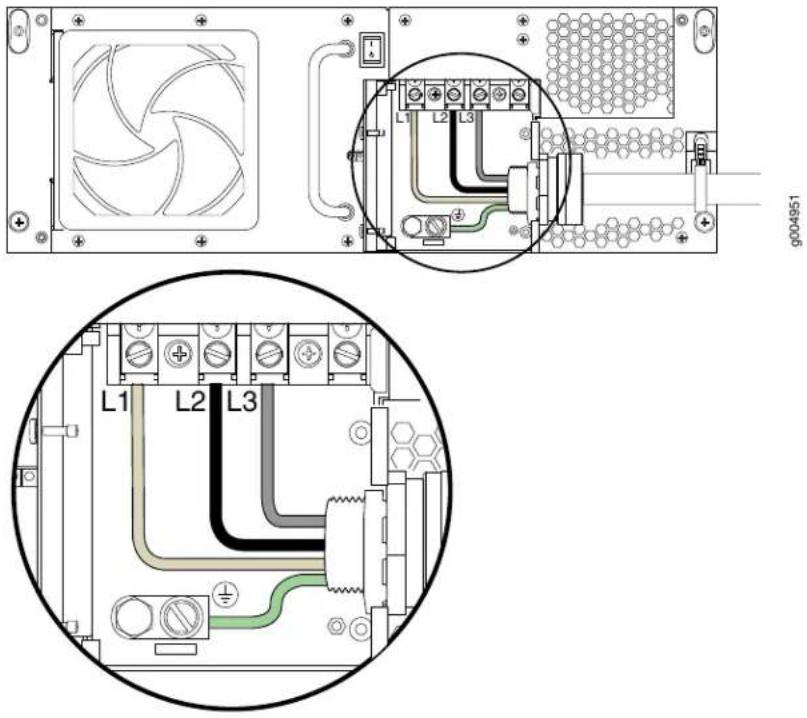

NOTE: The color of each AC power wire might vary.
- Verify that the power cable connections are correct.
- Using a number 2 Phillips (+) screwdriver, tighten the two captive screws on the metal AC wiring compartment.
-
Use the provided plastic cable tie to fasten the AC power cord to the power supply.
-
Verify that the AC power cord is not touching or blocking access to router components, and that it does not drape where people could trip on it.
- Repeat the procedure for the other three-phase delta AC power supply.
Related Documentation
T1600 Three-Phase Delta and Wye AC Power Supply Description on page 114.
• Powering On the AC-Powered T1600 Router on page 257
•T1600 AC Power Electrical Safety Guidelines
•T1600 AC Power Cord Specifications on page 151
•T1600 Preventing Electrostatic Discharge Damage on page 552
Connecting AC Power to a T1600 Router with Three-Phase Wye AC Power Supplies
To connect an AC power cord:
- Attach an electrostatic discharge (ESD) grounding strap to your bare wrist, and connect the strap to an approved site ESD grounding point. See the instructions for your site.
- Switch off the customer site circuit breakers. Ensure that the voltage across the AC power source is 0 V and that there is no chance that the voltage might become active during installation.
- Detach the ESD grounding strap from the approved site ESD grounding point, and connect the strap to one of the ESD points on the chassis.
- Switch the power switch on the power supply faceplate to the standby position.
- Using a number 2 Phillips (+) screwdriver, loosen the two captive screws on the metal AC wiring compartment.
- Open the metal door of the metal AC wiring compartment.
- Unscrew the retaining nut from the AC power cord.
- Place the retaining nut inside the metal wiring compartment.
- Put the wires of the AC power cord through the hole of the metal wiring compartment.
-
Screw the retaining nut onto the AC power cord to secure it to the metal wiring compartment.
-
Connect the wires to the AC terminal block on the three-phase wye AC power supply (Figure 117 on page 256). Loosen each of the input terminals or grounding point screws, insert each wire into the grounding point or input terminal, and tighten the screw.

NOTE: Theterminalconnections have either slotted screw or hex screws. Use a 1/4-in. slotted screwdriver for the slotted screws. Use a 5/32-in (4-mm) Allen wrench for the 5/16-in hex screws.
b. Insert the wire labeled L1 into the L1 input terminal.
c. Insert the wire labeled L2 into the L2 input terminal.
d. Insert the wire labeled L3 into the L3 input terminal.
e. Insert the wire labeled N into the N input terminal
a. Insert the wire labeled GND into the grounding point labeled GND.
Figure 117: Connecting Power to the Three-Phase Wye AC Power Supply
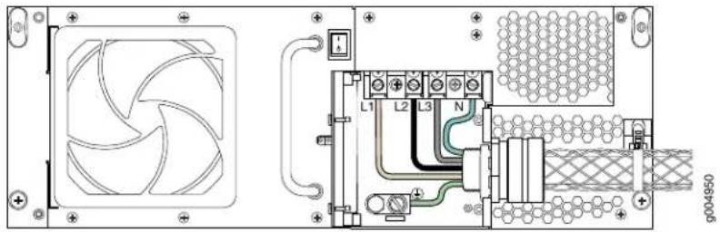
- Verify that the power cable connections are correct.
- Using a number 2 Phillips (+) screwdriver, tighten the two captive screws on the metal AC wiring compartment.
- Use the provided plastic cable tie to fasten the AC power cord to the power supply.
Figure 118: Fastening the AC Power Cord to the Power Supply

natural_image
Technical line drawing of an industrial power supply unit with fan, cooling unit, and pipe (no text or symbols)- Verify that the AC power cord is not touching or blocking access to router components, and that it does not drape where people could trip on it.
- Repeat the procedure for the other three-phase wye AC power supply.
Related Documentation
T1600 Three-Phase Delta and Wye AC Power Supply Description on page 114.
• Powering On the AC-Powered T1600 Router on page 257
•T1600 General Electrical Safety Guidelines on page 575
•T1600 AC Power Electrical Safety Guidelines
•T1600 AC Power Cord Specifications on page 151
•T1600 Preventing Electrostatic Discharge Damage on page 552
Powering On the AC-Powered T1600 Router
You can use this procedure for a router with either three-phase delta AC power supplies or three-phase wye AC power supplies. To power on the AC-powered router:
- Verify that the power supplies are fully inserted in the chassis and that the captive screws on their faceplates are tightened.
- Verify that the AC power cords are connected correctly.
- Verify that an external management device is connected to one of the Routing Engine ports on the CIP (AUXILIARY or CONSOLE).

NOTE: The management Ethernet port will not be functional until you have completed the initial configuration.
- Turn on the power to the external management device.
- Switch on the dedicated customer site circuit breakers to provide power to the AC power cables. Follow your site's procedures.
- Verify that the AC OK LED on both AC power supply faceplates are lit steadily green, indicating that the power supplies are receiving power.
- Attach an electrostatic discharge (ESD) grounding strap to your bare wrist, and connect the strap to one of the ESD points on the chassis.
- Switch the power switch on one of the power supplies to the ON position (I). The DC OK LED blinks momentarily, then lights steadily.

NOTE: After a power supply is powered on, it can take up to 60 seconds forstatus indicators—such as the output statusLEDs on the power supply, the command output, and messages on the LCD on the craft interface—to indicate that the power supply is functioning normally. Ignore error indicators that appear during the first 60 seconds.
- Verify that the DC OK LED on the AC power supply faceplate is lit steadily, indicating that power supply is correctly installed, functioning properly, and providing power to the DC outputs.
- On the external management device connected to the Routing Engine, monitor the startup process to verify that the system has booted properly.

NOTE: If the system is completely powered off when youpoweronthepower supply, the Routing Engine boots as the power supply completes its startup sequence. If the Routing Engine finishes booting, you must power off the router before powering it on again. After powering on a power supply, wait at least 60 seconds before turning it off. After powering off a power supply, wait at least 60 seconds before turning it back on.
Related Documentation
T1600 Three-Phase Delta and Wye AC Power Supply Description on page 114.
•Overview of Connecting the T1600 Router to External Devices on page 231
- Connecting the T1600 Router to a Management Console or Auxiliary Device on page 232
- Connecting AC Power to a T1600 Router with Three-Phase Delta AC Power Supplies on page 253
- Connecting AC Power to a T1600 Router with Three-Phase Wye AC Power Supplies on page 255
• Powering Off the T1600 Router on page 258
•T1600 Preventing Electrostatic Discharge Damage on page 552
•T1600 General Electrical Safety Guidelines on page 575
•T1600 AC Power Electrical Safety Guidelines
•T1600 Preventing Electrostatic Discharge Damage on page 552
Powering Off the T1600 Router
To power off a T320 router:
- On the external management device connected to the Routing Engine, issue the requestsystemhalt both-routing-engines operational modecommand. The command shuts down both Routing Engines cleanly, so their state information is preserved. (If the router contains only one Routing Engine, issue the request system halt command.)
user@host> request system halt both-routing-engines
For more information about these commands, see request system halt.
- Wait until a message appears on the console confirming that the operating system has halted.
Halt the system ? [yes, no] (no) yes
*** FINAL System shutdown message from root@section2 ***
System going down IMMEDIATELY
Terminated
...
syncing disks... 11 8 done
The operating system has halted.
Please press any key to reboot.
- Attach an electrostatic discharge (ESD) grounding strap to your bare wrist, and connect the strap to one of the ESD points on the chassis.
- Switch the circuit breakers on each power supply faceplate to the off position (O).
Related Documentation
•T1600 Preventing Electrostatic Discharge Damage on page 552
•T1600 General Electrical Safety Guidelines on page 575
CHAPTER 23
Configuring the JUNOS Software
- Initially Configuring the T1600 Router on page 261
- Configuring DC Power on a T1600 Router on page 266
Initially Configuring the T1600 Router
The T1600 Core Router is shipped with Junos OS preinstalled and ready to be configured when the T1600 router is powered on. These procedures connect a router to the network but do not enable it to forward traffic. For complete information about enabling the router to forward traffic, including examples, see the Junos OS configuration guides.
You configure the router by issuing Junos OS command-line interface (CLI) commands, either on a console device attached to the CONSOLE port on the CIP, or over a telnet connection to a network connected to the ETHERNET port on the CIP.

NOTE: These procedures enable you to use the ETHERNET management port. For the initial configuration, use a device attached to the CONSOLE port on the CIP.
For more information about the commands in this procedure see the Junos OS Administration Library for Routing Devices.
- Preparing to Configure the T1600 Router on page 261
- Entering Configuration Mode on page 262
- Configuring User Accounts and Passwords on page 262
- Configuring System Attributes on page 262
- Committing the Configuration on page 264
Preparing to Configure the T1600 Router
Gather the following information before configuring the router:
- Name the router will use on the network
- Domain name the router will use
- IP address and prefix length information for the Ethernet interface
• IP address of a default router
• IP address of a DNS server
- Password for the root user
Entering Configuration Mode
- Verify that the network device is powered on.
- Log in as the root user. There is no password.
- Start the CLI.
- Enter configuration mode.
Amnesiac <ttyd0>
login: root
root@% cll
root>
root> configure
Entering configuration mode.
[edit]
root#
Configuring User Accounts and Passwords
For information about using an encrypted password or an SSH public key string (DSA or RSA), see authentication.
- Add a password to the root administration user account. Enter a clear-text password.
[edit]
root# set system root-authentication plain-text-password
New password: password
Retype new password: password
- Create a management console user account.
[edit]
root# set system login user user-name authentication plain-text-password
New Password: password
Retype new password: password
- Set the user account class to super-user.
[edit]
root@# set system login user user-name class super-user
Configuring System Attributes
For more information on configuring the backup routing and static routes, see the Junos OS Administration Library for Routing Devices.
- Configure the name of the router. If the name includes spaces, enclose the name in quotation marks ("").
[edit]
root@host# set system host-name host-name

NOTE: TheDNS server does not use the hostname to resolvetothe correct IP address. This hostname is usedtodisplaythe name ofthe routing engine in the CLI. Forexample, this hostname showsonthe command-line prompt when the user is logged on to the CLI:
user-name@host-name>
- Configure the IP address of the DNS server.
[edit]
root# set system name-server address
- Configure the router's domain name.
[edit]
root@# set system domain-name domain-name
- Configure the IP address and prefix length for the router's management Ethernet interface.

NOTE: The RE-C1800 Routing Engine (RE-DUO-1800) does not support the fxp0 interface or the fxp1 and fxp2 internal Ethernet interfaces. Use the em0 interface for the RE-C1800 Routing Engine, and fxp0 interface for all other Routing Engines supported for the router.
[edit]
root@# set interfaces fxp0 unit 0 family inet address address/prefix-length
[edit]
root@# set interfaces em0 unit 0 family inet address address/prefix-length
- Configure the IP address of a backup routing engine. The backup routing engine is used while the local router is booting and if the routing process fails to start. After the routing process starts, the backup routing engine address is removed from the local routing and forwarding tables.
[edit]
root# set system backup-router address
- (Optional) Configure the static routes to remote subnets with access to the management port. Access to the management port is limited to the local subnet. To access the management port from a remote subnet, you must add a static route to that subnet within the routing table.
[edit]
root# set routing-options static route remote-subnet next-hop destination-IP retain no-readvertise
- Configure the telnet service at the [edit system services] hierarchy level.
[edit]
set system services telnet
Committing the Configuration
For a chassis with two Routing Engines, commit the configuration changes to both Routing Engines. When you issue the commit synchronize command, the configuration is shared between both Routing Engines and committed on both Routing Engines simultaneously. For a chassis with only one Routing Engine, use the commit command instead of the commit synchronize command.
- Display the configuration to verify that it is correct.
root# show
<h2 id="last-changed-2008-10-17-183225-utc">Last changed: 2008-10-17 18:32:25 UTC</h2>
version 9.1R1.8;
groups {
    re0 {
    system {
    host-name spice-re0;
    }
    interfaces {
    fxp0 {
    unit 0 {
    family inet {
    address 192.168.69.155/21;
    }
    }
    }
    }
    }
    rel {
    system {
    host-name spice-re1;
    }
    interfaces {
    fxp0 {
    unit 0 {
    family inet {
    address 192.168.70.72/21;
    }
    }
    }
    }
    global;
}
apply-groups [re0 rel];
system {
domain-name englab.juniper.net;
backup-router 192.168.71.254;
root-authentication {
encrypted-password "xxxxxxxxxxx"; ## SECRET-DATA
}
name-server {
192.168.1.1;
}
login {
user regress {
    uid 2001;
    class super-user;
    authentication {
    encrypted-password "xxxxxxxxxx"; ## SECRET-DATA
    }
    }
    services {
    telnet;
    }
    syslog {
    user * {
    any emergency;
    }
    file messages {
    any notice;
    authorization info;
    }
    file interactive-commands {
    interactive-commands any;
    }
    }
}
routing-options {
    static {
    /* corporate office */
    route 172.16.0.0/12 {
    next-hop 192.168.71.254;
    retain;
    no-readvertise;
    }
    }
}
- Commit the configuration to activate it, and synchronize the configuration. The commit synchronize command commits this new configuration on both Routing Engines simultaneously.
[edit]
root# commit synchronize
re0:
configuration check succeeds
re1:
commit complete
re0:
commit complete
If you receive an error message after you issue the commit statement, you can review the configuration using the show command to find the errors in your configuration. You can delete incorrect entries using the delete command. For example, to delete a hostname from the configuration, issue the following command:
[edit]
root# delete system host-name hostname
- (Optional) Configure additional properties by adding the necessary configuration statements. Then commit the changes to activate them.
[edit]
root@host# commit synchronize
- Exit configuration mode.
[edit]
root@host# exit
Exiting configuration mode
root>
Related T1600 Router Description on page 3.
Documentation
•Overview of Installing the T1600 Router on page 173
Configuring DC Power on a T1600 Router
After you have connected the DC power and initially configured the router, you need to configure the number of input feeds if you connected fewer than six cables to the six-input DC power supply.
For more information about configuring the DC power supply and the commands used in the procedures, see the Junos OS Administration Library for Routing Devices.
- Configuring DC Power on a T1600 Router (Five 60-A Cables on a Six-Input DC Power Supply) on page 266
Configuring DC Power on a T1600 Router (Five 60-A Cables on a Six-Input DC Power Supply)
When you connect five cables on a six-input DC power supply, you must specify the number of input feeds connected in the software. If the number of physical input feeds receiving power does not match the number of configured input feeds, the router displays an alarm message.
- Configure the number of input feeds to indicate that five DC power cables are connected.
[edit]
user@host# set chassis pem feeds 5

NOTE: The default number of input feeds is 6.
- (Optional) Use the show statement to display the configuration to verify that it is correct.
[edit]
user@host# show
pem {
    feeds 5;
}
- Commit the configuration to activate it on the router, and exit configuration mode.
[edit]
user@host# commit
user@host# exit
user@host>
Related
Documentation
•T1600 Power System Description on page 105
- Connecting DC Power to the T1600 Router (Five 60-A Inputs to Six-Input DC Power Supplies) on page 247
•Troubleshooting the T1600 Power System on page 516
•T1600 DC Power Requirements on page 140
•
CHAPTER 24
Upgrading to a T1600 Router from a Router
• Overview of Upgrading a T640 Router to a T1600 Router on page 269
- Hardware Required for Upgrading from a T640 Router to a T1600 Router on page 270
• T640 to T1600 Upgrade Kit on page 271
- Verifying the Hardware Versions Before an Upgrade to a T1600 Router on page 271
- Tools Required to Upgrade a T640 Router to a T1600 Router on page 278
- Upgrading to a Supported T1600 Rear Fan Tray on page 278
- Upgrading to Supported T1600 Power Supplies on page 280
- Upgrading to T1600 SIBs on page 284
- Upgrading to a T1600 Craft Interface on page 294
- Attaching the T1600 Agency Label on page 297
- Registering Your T1600 Upgrade on page 298
Overview of Upgrading a T640 Router to a T1600 Router

NOTE: The T640 router can be upgraded to a standaloneT1600 router while the router is powered on and operational.

NOTE: Do not install T1600-FPC4s until after all upgrade procedures are completed.
To upgrade the T640 router to a T1600 router:
- If you have not already done so, install JUNOS Release 8.5 or later in the T640 router.
- Verify that control boards supported for the T1600 router are installed. If needed, order supported control boards, and install them before upgrading the SIBs.
-
Verify that a rear fan tray supported for the T1600 routers is installed. If needed, order a supported rear fan tray, and install it before upgrading the power supplies.
-
Prepare the site. Provision additional power as needed.
- Verify that power supplies supported for the T1600 routers are installed. If needed, order supported power supplies. Replace the power supplies before upgrading the SIBs.
- Upgrade the existing standard SIBs to T1600-SIBs.

NOTE: During the SIB upgrade:
- The router should not experience packet loss if the traffic is less than 50 percent per Packet Forwarding Engine in each FPC.
- The router might experience some packet loss if the traffic is more than 50 percent per Packet Forwarding Engine in each FPC, depending on the operational environment.
For more information, contact your customer support representative.
- Remove the upper fan tray. See "Upgrading to a Supported T1600 Rear Fan Tray" on page 278.
- Replace the craft interface. "Upgrading to a T1600 Craft Interface" on page 294.
- Reinstall the upper fan tray. See "Upgrading to a Supported T1600 Rear Fan Tray" on page 278.
- Verify the installation of components.
- Attach the T1600 agency label.
- Register your T1600 upgrade.
Related
Documentation
T640 to T1600 Upgrade Kit on page 271.
•Verifying the Hardware Versions Before an Upgrade to a T1600 Router on page 271
Hardware Required for Upgrading from a T640 Router to a T1600 Router
To upgrade a T640 router to a standaloneT1600 router, you install the following hardware components:
- Two redundant, load-sharing power supplies. See “T1600 Power System Description” on page 105 for a list of power supplies supported for the T1600 router.

NOTE: You cannot mix different DC power supplies in the same router except during upgrade. DC power supplies and AC power supplies must not be mixed in the same router.
- Five T1600-SIBs.
- One T1600 craft interface panel.
- See "T1600 Control Boards Description" on page 66 for a list of control boards supported for the T1600 router.
For a T1600 router in a router matrix, additional components and different SIBs are required. See the TX Matrix Plus Router Hardware Guide for more information.
Related Documentation
T640 to T1600 Upgrade Kit on page 271.
•Overview of Upgrading a T640 Router to a T1600 Router on page 269
•Verifying the Hardware Versions Before an Upgrade to a T1600 Router on page 271
T640 to T1600 Upgrade Kit
You can order the required components individually or order a T1600 upgrade kit that contains various components. You might need to supply additional DC power cables, depending on your power supply.

NOTE: These components must be installed before you can install a T1600-FPC in the T1600 router.
Related Documentation
Overview of Upgrading a T640 Router to a T1600 Router on page 269.
- Verifying the Hardware Versions Before an Upgrade to a T1600 Router on page 271
Verifying the Hardware Versions Before an Upgrade to a T1600 Router
Before upgrading from a T640 router to a T1600 router, verify if the control boards, rear fan tray, and power supplies are supported for a T1600 router.
- Verifying the Hardware Version of the Control Board on page 272
- Verifying the Hardware Version of the Rear Fan Tray on page 275
- Verifying the Hardware Version of the Power Supplies on page 277
Verifying the Hardware Version of the Control Board
The T1600 router supports the following control boards:
• T Series control board (T-CB) model number (CB-T)

NOTE: The control board shown as CB-T in the CLI output is the T640 standard control board (model number CB-L-T), which is not supported for T1600 routers, and is not the T-series control board (model number CB-T).
• Line-card chassis control board (LCC-CB) model number (CB-LCC)
To verify that supported control boards are installed:
- Issue the show chassis hardware command on the T640 router.
In this example, the show chassis hardware output shows that two control boards shown as Control Board (CB-T) are installed. These control boards are the T640 standard control boards (model number CB-L-T), and not T Series control boards
user@host> show chassis hardware
Hardware inventory:
| Item | Version | Part number | Serial number | Description |
| Chassis | 65409 | T640 | ||
| Midplane | REV 03 | 710-005608 | RA1395 | T640 Backplane |
| FPM GBUS | REV 09 | 710-002901 | RA2649 | T640 FPM Board |
| FPM Display | REV 05 | 710-002897 | RA2608 | FPM Display |
| CIP | REV 06 | 710-002895 | HS0753 | T-series CIP |
| PEM 0 | Rev 01 | 740-002595 | MF16629 | Power Entry Module |
| SCG 0 | REV 11 | 710-003423 | HS4313 | T640 Sonet Clock Gen. |
| SCG 1 | REV 11 | 710-003423 | HR9161 | T640 Sonet Clock Gen. |
| Routing Engine 0 | REV 03 | 740-008883 | 211123900199 | RE-4.0 |
| Routing Engine 1 | REV 03 | 740-008883 | 211123900248 | RE-4.0 |
| CB 0 | REV 02 | 710-007655 | HS5909 | Control Board (CB-T) |
| CB 1 | REV 02 | 710-007655 | HS5910 | Control Board (CB-T) |
| FPC 1 | REV 07 | 710-007527 | HR0716 | FPC Type 2 |
| CPU | REV 15 | 710-001726 | HS6048 | FPC CPU |
| PIC 0 | REV 07 | 750-001900 | AR3722 | 1x OC-48 SONET, SMSR |
| PIC 1 | REV 05 | 750-001900 | AD3644 | 1x OC-48 SONET, SMSR |
| PIC 3 | REV 06 | 750-001900 | HD7603 | 1x OC-48 SONET, SMSR |
| MMB 1 | REV 03 | 710-005555 | HT5273 | MMB-288mbit |
| PPB 0 | REV 04 | 710-003758 | HR4249 | PPB Type 2 |
| PPB 1 | REV 04 | 710-003758 | HR4257 | PPB Type 2 |
| FPC 2 | REV 01 | 710-010233 | HM4189 | E-FPC Type 1 |
| CPU | REV 01 | 710-010169 | HS9936 | FPC CPU-Enhanced |
| PIC 1 | REV 03 | 750-005719 | HL8326 | 1x OC-12 ATM-II IQ, MM |
| PIC 2 | REV 01 | 750-003141 | AD9051 | 1x G/E, 1000 BASE-SX |
| MMB 1 | REV 01 | 710-008923 | HR0848 | MMB 3M 288-bit |
| FPC 3 | REV 01 | 710-010154 | HR0863 | E-FPC Type 3 |
| CPU | REV 01 | 710-010169 | HN3422 | FPC CPU-Enhanced |
| PIC 3 | REV 01 | 750-009553 | HP3576 | 4x OC-48 SONET |
| SFP 0 | REV 01 | 740-009030 | P11H5N1 | SFP-LR |
| SFP 1 | REV 01 | 740-009029 | 35D464P00060 | SFP-IR |
| SFP 3 | REV 01 | 740-009030 | P11H5LM | SFP-LR |
| MMB 0 | REV 01 | 710-010171 | HR0821 | MMB-288mbit |
| MMB 1 | REV 01 | 710-010171 | HR0818 | MMB-288mbit |
| SPMB 0 | REV 09 | 710-003229 | HT4177 | T-series Switch CPU |
| SPMB 1 | REV 09 | 710-003229 | HT4176 | T-series Switch CPU |
| SIB 0 | REV 07 | 710-005781 | HR5939 | SIB-L8-F16 |
| B Board | REV 06 | 710-005782 | HR5944 | SIB-L8-F16 (B) |
| SIB 1 | REV 02 | 710-005781 | HZ2146 | SIB-L8-F16 |
| B Board | REV 03 | 710-005782 | HY4160 | SIB-L8-F16 (B) |
| SIB 2 | REV 07 | 710-005781 | HR5925 | SIB-L8-F16 |
| B Board | REV 03 | 710-005782 | HY4161 | SIB-L8-F16 (B) |
| SIB 3 | REV 07 | 710-005781 | HR5918 | SIB-L8-F16 |
| B Board | REV 06 | 710-005782 | HR5972 | SIB-L8-F16 (B) |
| SIB 4 | REV 07 | 710-005781 | HR5935 | SIB-L8-F16 |
| B Board | REV 06 | 710-005782 | HR5969 | SIB-L8-F16 (B) |
In this example, the show chassis hardware output shows that two control boards shown as T-series Control Board are installed. These control boards are supported for a standalone T1600 router.
user@host> show chassis hardware
Hardware inventory:
| Item | Version | Part number | Serial number | Description |
| Chassis | JN1090E5DAHA | T1600 | ||
| Midplane | REV 02 | 710-017247 | RC0094 | T640 Backplane |
| FPM GBUS | REV 09 | 710-002901 | WE0156 | T640 FPM Board |
| FPM Display | REV 02 | 710-002897 | HE7864 | FPM Display |
| CIP | REV 06 | 710-002895 | WD8691 | T-series CIP |
| PEM 0 | Rev 06 | 740-017906 | TE27790 | Power Entry Module 3x80 |
| PEM 1 | Rev 06 | 740-017906 | TE27779 | Power Entry Module 3x80 |
| SCG 0 | REV 14 | 710-003423 | WF1874 | T640 Sonet Clock Gen. |
| SCG 1 | REV 14 | 710-003423 | WF1881 | T640 Sonet Clock Gen. |
| Routing Engine 0 | REV 06 | 740-014082 | 1000688671 | RE-A-2000 |
| Routing Engine 1 | REV 06 | 740-014082 | 1000688739 | RE-A-2000 |
| CB 0 | REV 15 | 710-002728 | HR8130 | T-series Control Board |
| CB 1 | REV 15 | 710-002728 | HR8130 | T-series Control Board |
| FPC 0 | REV 10 | 710-010845 | JZ2728 | FPC Type 4 |
| CPU | REV 04 | 710-011481 | JT8139 | FPC CPU-Enhanced |
| PIC 0 | REV 05 | 750-017405 | DF3515 | 4x 10GE (LAN/WAN) XFP |
| Xcvr 0 | REV 01 | 740-014279 | KB405P1 | XFP-10G-LR |
| Xcvr 1 | REV 01 | 740-014289 | C701XU05U | XFP-10G-SR |
| MMB 0 | REV 01 | 710-016606 | JW7943 | ST-MMB |
| FPC 1 | REV 03 | 710-013035 | DF5574 | FPC Type 3-ES |
| CPU | ||||
| FPC 2 | REV 04 | 710-013560 | WF7206 | E2-FPC Type 3 |
| CPU | REV 03 | 710-013563 | WE9007 | FPC CPU-Enhanced |
| PIC 0 | REV 16 | 750-007141 | NF5528 | 10x 1GE(LAN), 1000 BASE |
| Xcvr 0 | REV 01 | 740-011782 | P8P085F | SFP-SX |
| PIC 1 | REV 12 | 750-009567 | WF3566 | 1x 10GE(LAN), XENPAK |
| Xcvr 0 | REV 02 | 740-013170 | T07C94489 | XENPAK-LR |
| PIC 2 | REV 11 | 750-009567 | CW9479 | 1x 10GE(LAN), XENPAK |
| Xcvr 0 | REV 02 | 740-013170 | T06F90331 | XENPAK-LR |
| PIC 3 | REV 07 | 750-012793 | WF5106 | 1x 10GE(LAN/WAN) IQ2 |
| Xcvr 0 | REV 01 | 740-014279 | KB405Q8 | XFP-10G-LR |
| MMB 0 | REV 06 | 710-010171 | WF6759 | MMB-5M3-288mbit |
| MMB 1 | REV 06 | 710-010171 | WF6800 | MMB-5M3-288mbit |
| FPC 3 | REV 04 | 710-013553 | JW1482 | E2-FPC Type 1 |
| CPU | REV 02 | 710-013563 | JY4119 | FPC CPU-Enhanced |
| PIC 0 | REV 10 | 750-012266 | JX5515 | 4x 1GE(LAN), IQ2 |
| Xcvr 0 | REV 01 | 740-011613 | PAM2Y9H | SFP-SX |
| Xcvr 1 | REV 01 | 740-011613 | PAM2Y99 | SFP-SX |
| Xcvr 2 | REV 01 | 740-011613 | AM07287E42 | SFP-SX |
| Xcvr 3 | REV 01 | 740-011613 | PAJ4SQL | SFP-SX |
| PIC 1 | REV 04 | 750-011209 | HY3332 | Adaptive Services-II |
| PIC 2 | REV 03 | 750-011750 | JH4537 | Adaptive Services-II FIPS |
| MMB 1 | REV 05 | 710-008923 | JS8106 | MMB 3M 288-bit |
| FPC 4 | REV 04 | 710-013558 | JX5622 | E2-FPC Type 2 |
| CPU | REV 02 | 710-013563 | JT5841 | FPC CPU-Enhanced |
| PIC 3 | REV 21 | 750-001901 | HZ6258 | 4x OC-12 SONET, SMIR |
| MMB 1 | REV 05 | 710-010171 | JY3756 | MMB-5M3-288mbit |
| FPC 5 | REV 10 | 710-010845 | JZ2728 | FPC Type 4 |
| CPU | REV 04 | 710-011481 | JT8139 | FPC CPU-Enhanced |
| PIC 0 | REV 01 | 750-010850 | JA0329 | 1x OC-768 SONET SR |
| MMB 0 | REV 01 | 710-016606 | JW7943 | ST-MMB |
| FPC 6 | REV 10 | 710-010845 | JZ2729 | FPC Type 4 |
| CPU | REV 04 | 710-011481 | JT8138 | FPC CPU-Enhanced |
| PIC 0 | REV 01 | 750-010850 | JA0324 | 1x OC-768 SONET SR |
| MMB 0 | REV 01 | 710-016606 | JW7942 | ST-MMB |
| FPC 7 | REV 05 | 710-013558 | WF4779 | E2-FPC Type 2 |
| CPU | REV 03 | 710-013563 | WF4663 | FPC CPU-Enhanced |
| PIC 0 | REV 09 | 750-011800 | KA2397 | 8x 1GE(LAN), IQ2 |
| Xcvr 0 | REV 01 | 740-007326 | P5SOPD9 | SFP-SX |
| Xcvr 1 | REV 01 | 740-007326 | P5SOPD6 | SFP-SX |
| Xcvr 2 | REV 01 | 740-011613 | PAJ4SQV | SFP-SX |
| Xcvr 3 | REV 01 | 740-011613 | PAM2Y94 | SFP-SX |
| Xcvr 5 | REV 01 | 740-011613 | P9R0AJV | SFP-SX |
| Xcvr 7 | REV 01 | 740-013111 | 70191002 | SFP-T |
| MMB 1 | REV 06 | 710-010171 | WF4050 | MMB-5M3-288mbit |
| SPMB 0 | REV 10 | 710-003229 | JZ1095 | T-series Switch CPU |
| SPMB 1 | REV 09 | 710-003229 | HR8670 | T-series Switch CPU |
| SIB 0 | REV 01 | 710-005157 | HJ9026 | SIB-I8-F16 |
| SIB 1 | REV 01 | 710-005157 | HJ4791 | SIB-I8-F16 |
| SIB 2 | REV 01 | 710-005157 | HJ4774 | SIB-I8-F16 |
| SIB 3 | REV 01 | 710-005157 | HJ4792 | SIB-I8-F16 |
| SIB 4 | REV 01 | 710-005157 | HJ4793 | SIB-I8-F16 |
2. Issue the show chassis hardware models command on the T640 router.
In this example, the show chassis hardware models output shows that two control boards shown as CB-L-T-S are installed. These control boards are the T640 standard control boards (model number CB-L-T), and not supported for the T1600 router.
user@host> show chassis hardware models
Hardware inventory:
| Item | Version | Part number | CLEI code | FRU model number |
| Midplane | REV 04 | 710-002726 | CHAS-BP-T640-S | |
| FPM Display | REV 02 | 710-002897 | CRAFT-T640-S | |
| CIP | REV 05 | 710-002895 | CIP-L-T640-S | |
| PEM 0 | Rev 01 | 740-002595 | PWR-T-DC-S | |
| SCG 0 | REV 04 | 710-003423 | SCG-T-S | |
| SCG 1 | REV 04 | 710-003423 | SCG-T-S | |
| Routing Engine 0 | REV 01 | 740-005022 | RE-600-2048-S | |
| Routing Engine 1 | REV 07 | 740-005022 | RE-600-2048-S | |
| CB 0 | REV 06 | 710-002726 | CB-L-T-S | |
| CB 1 | REV 06 | 710-002728 | CB-L-T-S | |
| FPC 5 | REV 05 | 710-007527 | T640-FPC2 | |
| PIC 0 | REV 05 | 750-002510 | PB-2GE-SX | |
| PIC 1 | REV 05 | 750-001901 | PB-40C12-SON-SMIR | |
| FPC 6 | REV 03 | 710-001721 | T640-FPC3 | |
| PIC 1 | REV 01 | 750-009553 | PC-40C48-SON-SFP | |
| SIB 4 | REV 02 | 750-005486 | SIB-I-T640-S | |
| Fan Tray 0 | FANTRAY-T-S |
Fan Tray 1
Fan Tray 2
FANTRAY-T-S
FAN-REAR-TX-T640-S
- If model number CB-L-T is installed, order control boards supported by the T1600 router, and install them on your T640 router before upgrading to a T1600 router.
Verifying the Hardware Version of the Rear Fan Tray
The T1600 router supports the following rear fan trays:
• Model number FAN-REAR-TX-T640
• Model number FAN-REAR-TXP-LCC

NOTE: This fan tray is required for T1600 routers in a routing matrix.
• Model number FAN-R
The supported rear fan trays have eight fans, which are required to support the additional thermal power generation of the T1600 router. Model number RHTREARTRAY-T has five blowers and does not provide sufficient cooling for the T1600 router.
To verify that a supported rear fan tray is installed:
- Issue the show chassis hardware models command on the T640 router.
In this example, the show chassis hardware models output shows that the rear fan tray shown as FRU model numberFAN-REAR-TX-T640-S is installed. This rear fan tray is supported for the T1600 router.
user@host> show chassis hardware models
Hardware inventory:
| Item | Version | Part number | CLEI code | FRU model number |
| Midplane | REV 04 | 710-002726 | CHAS-BP-T640-S | |
| FPM Display | REV 02 | 710-002897 | CRAFT-T640-S | |
| CIP | REV 05 | 710-002895 | CIP-L-T640-S | |
| PEM 0 | Rev 01 | 740-002595 | PWR-T-DC-S | |
| PEM 1 | Rev 01 | 740-002595 | PWR-T-DC-S | |
| SCG 0 | REV 04 | 710-003423 | SCG-T-S | |
| SCG 1 | REV 04 | 710-003423 | SCG-T-S | |
| Routing Engine 0 | REV 01 | 740-005022 | RE-600-2048-S | |
| Routing Engine 1 | REV 07 | 740-005022 | RE-600-2048-S | |
| CB 0 | REV 06 | 710-002726 | CB-L-T-S | |
| CB 1 | REV 06 | 710-002728 | CB-L-T-S | |
| FPC 5 | REV 05 | 710-007527 | T640-FPC2 | |
| PIC 0 | REV 05 | 750-002510 | PB-2GE-SX | |
| PIC 1 | REV 05 | 750-001901 | PB-40C12-SON-SMIR | |
| FPC 6 | REV 03 | 710-001721 | T640-FPC3 | |
| PIC 1 | REV 01 | 750-009553 | PC-40C48-SON-SFP | |
| SIB 4 | REV 02 | 750-005486 | SIB-I-T640-S | |
| Fan Tray 0 | FANTRAY-T-S | |||
| Fan Tray 1 | FANTRAY-T-S | |||
| Fan Tray 2 | FAN-REAR-TX-T640-S |
- Issue the show chassis environment command:
In this example, the output shows that the rear fan tray has five blowers, indicating that the model number RHTREARTRAY-T rear fan tray is installed. The last five lines of the output for the fans each include Blower in the description.
user@host> show chassis environment
| Fans | Top Left Front fan | OK | Spinning at normal speed |
| Top Left Middle fan | OK | Spinning at normal speed | |
| Top Left Rear fan | OK | Spinning at normal speed | |
| Top Right Front fan | OK | Spinning at normal speed | |
| Top Right Middle fan | OK | Spinning at normal speed | |
| Top Right Rear fan | OK | Spinning at normal speed | |
| Bottom Left Front fan | OK | Spinning at normal speed | |
| Bottom Left Middle fan | OK | Spinning at normal speed | |
| Bottom Left Rear fan | OK | Spinning at normal speed | |
| Bottom Right Front fan | OK | Spinning at normal speed | |
| Bottom Right Middle fan | OK | Spinning at normal speed | |
| Bottom Right Rear fan | OK | Spinning at normal speed | |
| Fourth Blower from top | OK | Spinning at normal speed | |
| Bottom Blower | OK | Spinning at normal speed | |
| Middle Blower | OK | Spinning at normal speed | |
| Top Blower | OK | Spinning at normal speed | |
| Second Blower from top | OK | Spinning at normal speed |
In this example, the output shows that the rear fan tray has eight fans, indicating that the model number FAN-REAR-TX-T640-S rear fan tray is installed. The last eight lines of the output for the fans each begin with Rear Tray and include fan in the description.
user@host> show chassis environment
| Fans | Top Left Front fan | OK | Spinning at normal speed |
| Top Left Middle fan | OK | Spinning at normal speed | |
| Top Left Rear fan | OK | Spinning at normal speed | |
| Top Right Front fan | OK | Spinning at normal speed | |
| Top Right Middle fan | OK | Spinning at normal speed | |
| Top Right Rear fan | OK | Spinning at normal speed | |
| Bottom Left Front fan | OK | Spinning at normal speed | |
| Bottom Left Middle fan | OK | Spinning at normal speed | |
| Bottom Left Rear fan | OK | Spinning at normal speed | |
| Bottom Right Front fan | OK | Spinning at normal speed | |
| Bottom Right Middle fan | OK | Spinning at normal speed | |
| Bottom Right Rear fan | OK | Spinning at normal speed | |
| Rear Tray Top fan | OK | Spinning at normal speed | |
| Rear Tray Second fan | OK | Spinning at normal speed | |
| Rear Tray Third fan | OK | Spinning at normal speed | |
| Rear Tray Fourth fan | OK | Spinning at normal speed | |
| Rear Tray Fifth fan | OK | Spinning at normal speed | |
| Rear Tray Sixth fan | OK | Spinning at normal speed | |
| Rear Tray Seventh fan | OK | Spinning at normal speed | |
| Rear Tray Bottom fan | OK | Spinning at normal speed |
- If model number RHTREARTRAY-T with five blowers is installed, order a supported rear fan tray, and install it before installing the power supplies supported for the T1600 router.
Verifying the Hardware Version of the Power Supplies
The T1600 router supports the following power supplies
- Three-input 240-A DC power supply (model number PWR-T1600-3-80-DC)
- Four-input 240-A DC power supply (model number PWR-T1600-4-60-DC)
- Six-input DC power supply (model number PWR-T-6-60-DC)
- Three-phase delta AC power supply (model number (PWR-T-10KW-DELTA-AC))
- Three-phase wye AC power supply (model number PWR-T-10KW-WYE-AC)
The T1600 router does not support the two-input 180-A DC power supply (model number PWR-T-DC).
To verify that supported power supplies are installed:
- Issue the show chassis hardware models command on the T640 router.
In this example, the show chassis hardware models output shows that two power supplies shown as FRU model number PWR-T-DC-S are installed. These power supplies are the 2-input 160-A DC power supplies (model number PWR-T-DC), and not supported for the T1600 router.
user@host> show chassis hardware models
Hardware inventory:
| Item | Version | Part number | CLEI code | FRU model number |
| Midplane | REV 04 | 710-002726 | CHAS-BP-T640-S | |
| FPM Display | REV 02 | 710-002897 | CRAFT-T640-S | |
| CIP | REV 05 | 710-002895 | CIP-L-T640-S | |
| PEM 0 | Rev 01 | 740-002595 | PWR-T-DC-S | |
| PEM 1 | Rev 01 | 740-002595 | PWR-T-DC-S | |
| SCG 0 | REV 04 | 710-003423 | SCG-T-S | |
| SCG 1 | REV 04 | 710-003423 | SCG-T-S | |
| Routing Engine 0 | REV 01 | 740-005022 | RE-600-2048-S | |
| Routing Engine 1 | REV 07 | 740-005022 | RE-600-2048-S | |
| CB 0 | REV 06 | 710-002726 | CB-L-T-S | |
| CB 1 | REV 06 | 710-002728 | CB-L-T-S | |
| FPC 5 | REV 05 | 710-007527 | T640-FPC2 | |
| PIC 0 | REV 05 | 750-002510 | PB-2GE-SX | |
| PIC 1 | REV 05 | 750-001901 | PB-40C12-SON-SMIR | |
| FPC 6 | REV 03 | 710-001721 | T640-FPC3 | |
| PIC 1 | REV 01 | 750-009553 | PC-40C48-SON-SFP | |
| SIB 0 | REV 02 | 750-005486 | SIB-I-T640-S | |
| SIB 1 | REV 02 | 750-005486 | SIB-I-T640-S | |
| SIB 2 | REV 02 | 750-005486 | SIB-I-T640-S | |
| SIB 3 | REV 02 | 750-005486 | SIB-I-T640-S | |
| SIB 4 | REV 02 | 750-005486 | SIB-I-T640-S | |
| Fan Tray 0 | FANTRAY-T-S | |||
| Fan Tray 1 | FANTRAY-T-S | |||
| Fan Tray 2 | FAN-REAR-TX-T640-S |
- If two-input 160-A DC power supplies (model number PWR-T-DC) are installed in your T640 router, order power supplies supported by the T1600 router, and install them on your T640 router before upgrading to a T1600 router.
Related T1600 Hardware Component Overview on page 15. Documentation
Tools Required to Upgrade a T640 Router to a T1600 Router
To upgrade the SIBs, you need the following tools and parts.
• Electrostatic discharge (ESD) grounding wrist strap
• Phillips (+) screwdrivers, numbers 1 and 2
Related Documentation Overview of Upgrading a T640 Router to a T1600 Router on page 269.
Upgrading to a Supported T1600 Rear Fan Tray
- Removing the RHTREARTRAY-T Rear Fan Tray on page 278
- Installing a Rear Fan Tray on page 279
Removing the RHTREARTRAY-T Rear Fan Tray
The rear fan tray is mounted vertically on the right side of the rear of the chassis. The rear fan tray (model number RHTREARTRAY-T) weighs about 12 lb (5.4 kg).
CAUTION: To maintain proper cooling, do not operate the router with the rear fan tray removed for more than 1 minute.
To remove the rear fan tray (see Figure 119 on page 279):
- Attach an electrostatic discharge (ESD) grounding strap to your bare wrist, and connect the strap to one of the ESD points on the chassis.
- Loosen the captive screws on the top and bottom of the fan tray faceplate, using a Phillips (+) screwdriver, number 2.
- Grasp the handles and pull the fan tray halfway out of the chassis.
WARNING: To avoid injury, keep tools and your fingers away from the fans asyouslide the fan tray out of the chassis. The fans might still be spinning.
- When the fans stop spinning, grasp the handles and pull the fan tray completely out of the chassis.
Figure 119: Removing the Rear RHTREARTRAY-T Fan Tray
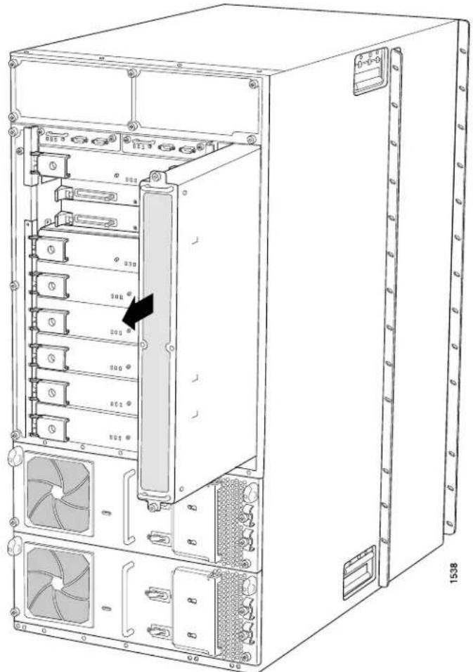
natural_image
Technical line drawing of a server rack unit with multiple drive bays and fan dividers (no text or labels)Installing a Rear Fan Tray
The rear fan tray (model number FAN-REAR-TX-T640-S) weighs about 10 pounds (4.5 kg). To install a replacement rear fan tray (see Figure 120 on page 280):
- Attach an electrostatic discharge (ESD) grounding strap to your bare wrist, and connect the strap to one of the ESD points on the chassis.
- Grasp the fan tray by its handles and insert it straight into the chassis.
- Tighten the captive screws on the fan tray faceplate to secure it in the chassis, using a Phillips (+) screwdriver, number 2.
Figure 120: Installing a Rear Fan Tray
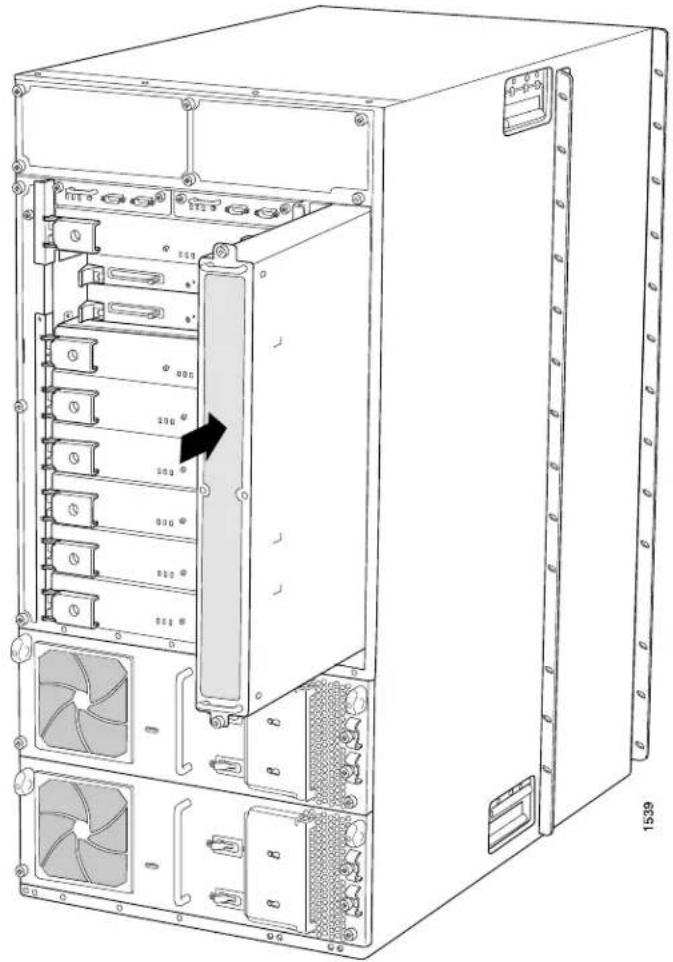
natural_image
Technical line drawing of a server rack unit with multiple drive bays and fan holders (no text or labels)Related Documentation
Hardware Required for Upgrading from a T640 Router to a T1600 Router on page 270.
•T640 to T1600 Upgrade Kit on page 271
•Overview of Upgrading a T640 Router to a T1600 Router on page 269
•Tools Required to Upgrade a T640 Router to a T1600 Router on page 278
•Verifying the Hardware Versions Before an Upgrade to a T1600 Router on page 271
Upgrading to Supported T1600 Power Supplies
- Removing a Two-Input 160-A DC Power Supply on page 281
• Installing a T1600 Power Supply on page 283
Removing a Two-Input 160-A DC Power Supply
The power supplies are located at the rear of the chassis below the SIBs. Each two-input 160-A power supply weighs approximately 23 lb (10.5 kg).

CAUTION: Do not leave a power supply slot empty for more than 30 minutes while the router is operational. For proper airflow, the power supply must remain in the chassis, or a blank panel must be used in an empty slot.
To remove a power supply:
- Make sure that the voltage across the DC power source cable leads is 0 V and that there is no chance that the cables might become active during the removal process.

CAUTION: You must ensure that power connections maintain the proper polarity. The power source cables might be labeled (+) and (−) to indicate their polarity. There is no standard color coding for DC power cables. The color coding used by the external DC power source at your site determines the color coding for the leads on the power cables that attach to the terminal studs on each power supply.
-
For a nonredundant power supply, power off the system. See the T640 Core Router Hardware Guide. For redundant power supplies, check that the other power supply is functional.
-
Attach an electrostatic discharge (ESD) grounding strap to your bare wrist, and connect the strap to one of the ESD points on the chassis.
-
Switch the circuit breakers on the power supply faceplate to the off position (O).

NOTE: After powering off a power supply, you must wait at least 60 seconds before turning it back on.
-
Remove the clear plastic cover protecting the terminal studs on the faceplate.
-
Remove the nuts and washers from the terminal studs (see Figure 121 on page 282). Use a 7/16-in. (11 mm) nut driver.
Figure 121: Disconnecting Power Cables from a Two-Input 160-A DC Power Supply

-
Remove the cable lugs from the terminal studs.
-
Loosen the captive screws on the cable restraints on the right edge of the power supply faceplate.
-
Carefully move the power cables out of the way.
-
Loosen the captive screws on the lower corners of the power supply faceplate completely. Twist the ejector handles on the upper corners of the faceplate counterclockwise to unseat the power supply.
-
Twist the ejector handles on the upper corners of the faceplate counterclockwise to unseat the power supply.
-
Grasp the handle on the power supply faceplate, and pull firmly to start removing the power supply. Slide it halfway out of the chassis (see Figure 122 on page 283).

WARNING: Do not touch the power connectors on the rear of the power supply (see Figure 123 on page 283). They can contain dangerous voltages.
- Place one hand underneath the power supply to support it and slide it completely out of the chassis.

CAUTION: Each two-input 160-A power supply weighs approximately 23 lb (10.5 kg). Be prepared to support the full weight of the power supply as you remove it from the router.
Figure 122: Removing a Power Supply
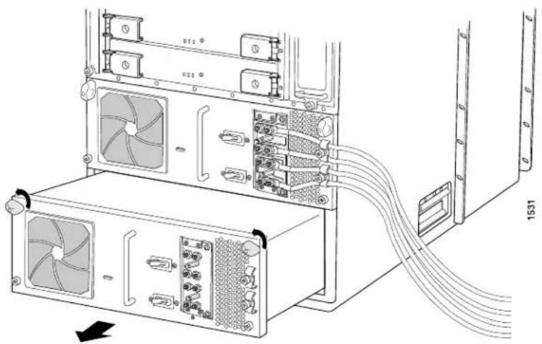
natural_image
Technical diagram of a server rack with connected ports and fans, showing internal wiring (no text or symbols)Figure 123: Rear of the Power Supply Showing Midplane Connectors
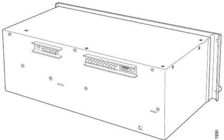
natural_image
Line drawing of a rectangular electronic device casing with internal components and mounting holes (no text or symbols)Installing a T1600 Power Supply
For a list of power supplies supported by the T1600 router, see "T1600 Power System Description" on page 105. For the procedure to install a power supply, see "Replacing a T1600 Routing Engine" on page 356.
To install DC power supplies:
- Install one power supply.
- Connect power to the DC power supply.
For procedures to connect power, see the following topics:
- Connecting DC Power to the T1600 Router (Three-Input 240-A DC Power Supplies or Four-Input 240-A DC Power Supplies) on page 240
- Connecting DC Power to the T1600 Router (Six 60-A Inputs to Six-Input DC Power Supplies) on page 243
-
Connecting DC Power to the T1600 Router (Five 60-A Inputs to Six-Input DC Power Supplies) on page 247
-
Repeat the procedure for the other DC power supply.

NOTE: Before installing AC power supplies, the router must be powered down, and both DC power supplies must be removed. Mixing DC power supplies and AC power supplies in the same router is not supported.
When upgrading to AC power supplies:
- Install the power supplies.
- Connect power to the power supplies.
- Connecting AC Power to a T1600 Router with Three-Phase Delta AC Power Supplies on page 253
- Connecting AC Power to a T1600 Router with Three-Phase Wye AC Power Supplies on page 255
- Power on the router. See "Powering On the AC-Powered T1600 Router" on page 257.
Related Documentation
Hardware Required for Upgrading from a T640 Router to a T1600 Router on page 270.
•T640 to T1600 Upgrade Kit on page 271
•Overview of Upgrading a T640 Router to a T1600 Router on page 269
- Tools Required to Upgrade a T640 Router to a T1600 Router on page 278
•Verifying the Hardware Versions Before an Upgrade to a T1600 Router on page 271
Upgrading to T1600 SIBs
To convert an operational T640 router to a T1600 router, you upgrade the standard SIBs or SIBs version B in the T640 router to T1600-SIBs or LCC-SIBs. You repeat the upgrade procedures for each of the five SIBs in the router.

NOTE: During the SIB upgrade:
- The router should not experience packet loss if the traffic is less than 50 percent per Packet Forwarding Engine in each FPC.
- The router might experience some packet loss if the traffic is more than 50 percent per Packet Forwarding Engine in each FPC, depending on the operational environment.
For more information, contact your customer support representative.
- Preparing to Upgrade the SIBs on page 285
- Removing a Standard SIB or SIB Version B on page 286
- Installing a T1600-SIB on page 287
- Verifying the Installation of a T1600-SIB on page 288
- Exiting Upgrade Mode on page 289
- Verifying Operation on page 290
Preparing to Upgrade the SIBs
To prepare to upgrade the SIBs:
- The T640 router must contain five standard SIBs or SIBs version B before the upgrade. Verify that four SIBs are in the Online state and one SIB is in the Spare state. Display the status of the SIBs by issuing the show chassis sibs command:
user@host> show chassis sibs
| Slot | State | Uptime |
| 0 | Spare | 255 days, 30 minutes, 12 seconds |
| 1 | Online | 255 days, 25 minutes, 45 seconds |
| 2 | Online | 255 days, 20 minutes, 28 seconds |
| 3 | Online | 255 days, 15 minutes, 7 seconds |
| 4 | Online | 255 days, 10 minutes, 52 seconds |
To bring a SIB online, issue the request chassis sib online operational mode command.
To install additional SIBs, use the standard installation procedure described in the T640 Core Router Hardware Guide.

NOTE: Do not proceed with the upgrade until all five SIBs are present and operational.
- Enter configuration mode.
user@host> configure
- Include the fabric upgrade-mode statement in the configuration at the [edit chassis] hierarchy level.
user@host# set chassis fabric upgrade-mode
-
Commit the configuration:
-
If GRES is enabled, commit the configuration on both the master and the backup Routing Engines:
user@host# commit synchronize -
If GRES is not enabled, commit the configuration on the master Routing Engine:
user@host# commit -
Exit configuration mode.
user@host# exit
Removing a Standard SIB or SIB Version B

NOTE: Replace the spare SIBfirst, and verify the operation of the replacement before replacing the other SIBs.
To remove a standard SIB or SIB version B:
- Attach an electrostatic discharge (ESD) grounding strap to your bare wrist and connect the strap to one of the ESD points on the chassis.
- Take the SIB offline by using one of the following methods:
- Press and hold the ONLINE/OFFLINE button on the SIB faceplate for about five seconds until the OK LED is not lit.
- Issue the request chassis sib offline command. For example:
user@host> request chassis sib offline slot 0

NOTE: When you bring an active SIB offline, the spare SIB becomes active and transitions to the Online state.
- Loosen the captive screws (using a Phillips (+) screwdriver, number 2) on the ejector handles on each side of the SIB faceplate.
- Flip the ejector handles outward to unseat the SIB.
- Grasp both ejector handles, pull firmly, and slide the SIB about three-quarters of the way out of the chassis.
- Place one hand underneath the SIB to support it and slide it completely out of the chassis. Place the SIB on the antistatic mat.

CAUTION: Do not stack hardware components on one another after you remove them. Place each component on an antistatic mat resting on a stable, flat surface.
Figure 124: Removing a SIB from a T640 Router

natural_image
Technical line drawing of an electronic device chassis with labeled ports and mounting brackets (no text or symbols present)Figure 125: Standard SIB Supported in a T640 Router
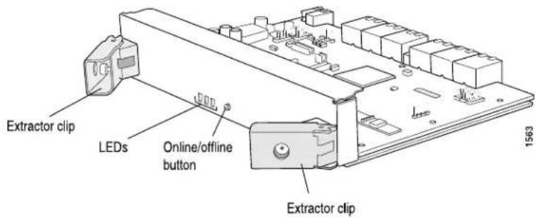
Installing a T1600-SIB
Each T1600-SIB weighs approximately 6.5 lb (3 kg). To install a T1600-SIB (see Figure 126 on page 288):
- Attach an electrostatic discharge (ESD) grounding strap to your bare wrist and connect the strap to one of the ESD points on the chassis.
- Place one hand underneath the T1600-SIB to support it. With the other hand, hold one of the ejector handles on the T1600-SIB faceplate.
- Carefully align the sides of the T1600-SIB with the guides inside the chassis.
- Slide the T1600-SIB into the chassis, carefully ensuring that it is correctly aligned.
-
Grasp both ejector handles and press them inward to seat the T1600-SIB. Ensure that the ejector handle tabs are properly mated inside their corresponding chassis slots. You might have to close and open the handles a few times before the tabs catch the slots.
-
Tighten the captive screws on the ejector handles.
-
Bring the T1600-SIB online using one of the following methods:
-
Press and hold the ONLINE/OFFLINE button on the T1600-SIB faceplate. The green OK LED on the faceplate begins to blink. Hold the button down until the LED blinks.
- Issue the following CLI command on the router: user@host> request chassis sib online slot 0
Figure 126: Installing a T1600-SIB

natural_image
Technical line drawing of an internal server rack unit with labeled ports and mounting points (no text or symbols beyond labels)Verifying the Installation of a T1600-SIB
To verify that the T1600-SIB is functioning normally:
-
Check the LEDs on the T1600-SIB faceplate.
-
The green OK LED should light steadily a few minutes after the T1600-SIB is installed.
-
If the FAIL LED is lit steadily, remove and install the T1600-SIB again. Make sure that the T1600-SIB is seated properly. If the FAIL LED still lights steadily, the T1600-SIB is not functioning properly. Contact your customer support representative.
-
Verify that four T1600-SIB are in the Online state and one SIB is in the Spare state.
Display the status of the T1600-SIB by issuing the show chassis sibs command:
user@host> show chassis sibs
| Slot | State | Uptime |
| 0 | Spare | 0 days, 30 minutes, 12 seconds |
| 1 | Online | 0 days, 25 minutes, 45 seconds |
| 2 | Online | 0 days, 20 minutes, 28 seconds |
| 3 | Online | 0 days, 15 minutes, 7 seconds |
| 4 | Online | 0 days, 10 minutes, 52 seconds |
To bring a T1600-SIB online, issue the request chassis slb online operational mode command.
Exiting Upgrade Mode
After all five T1600-SIBs have been installed, exit upgrade mode:
- Determine if graceful Routing Engine switchover (GRES) is enabled.
user@host> show system switchover
Graceful switchover: On
Configuration database: Ready
Kernel database: Ready
- Verify that the Routing Engines are operating properly by issuing the show chassis routing-engine command.
user@host> show chassis routing-engine
Routing Engine status: Slot 0:
Current state Master
Election priority Master (default)
Temperature 32 degrees C / 89 degrees F
CPU temperature 33 degrees C / 91 degrees F
DRAM 2048 MB
Memory utilization 8 percent
CPU utilization:
User 0 percent
Background 0 percent
Kernel 2 percent
Interrupt 0 percent
Idle 98 percent
Model RE-4.0
Serial ID P13004101110
Start time 2007-04-30 08:38:22 PDT
Uptime 2 days, 2 hours, 22 minutes, 43 seconds
Load averages: 1 minute 5 minute 15 minute
0.02 0.02 0.00
- Enter configuration mode.
user@host> configure
- Delete the fabric upgrade-mode statement in the configuration at the [edit chassis] hierarchy level.
user@host# delete chassis fabric upgrade-mode
- Commit the configuration:
- If GRES is enabled, commit the configuration on both the master and the backup Routing Engines:
user@host# commit synchronize
- If GRES is not enabled, commit the configuration on the master Routing Engine: user@host# commit
- Exit configuration mode.
user@host# exit
Verifying Operation
Use the following commands to verify proper operation of the T1600 router:
- Verify that the model number is now T1600 by issuing the show version command.
user@host> show version
Hostname: myhost
Model: t1600
JUNOS Base OS boot [8.5R1]
JUNOS Base OS Software Suite [8.5R1]
JUNOS Kernel Software Suite [8.5R1]
JUNOS Crypto Software Suite [8.5R1]
JUNOS Packet Forwarding Engine Support (M/T Common) [8.5R1] JUNOS Packet Forwarding Engine Support
(T-Series) [8.5R1] JUNOS Online Documentation [8.5R1] JUNOS Routing Software Suite [8.5R1]
- Verify that no alarms are present by issuing the show chassis alarms command.
user@host> show chassis alarms
No alarms currently active
- Verify that the LEDs and indicators on the craft interface show that the router is operating properly by issuing the show chassis craft-interface command.
user@host> show chassis craft-interface
FPM Display contents:

Front Panel System LEDs:
Routing Engine 0 1
| OK | * | * |
| Fail | . | . |
| Master | * | . |
Front Panel Alarm Indicators:
Red LED
Yellow LED .
Major relay.
Minor relay.
Front Panel FPC LEDs:
| FPC | 0 | 1 | 2 | 3 | 4 | 5 | 6 | 7 |
| Red | . | . | . | . | . | . | . | . |
| Green | * | * | * | * | * | * | * | * |
CB LEDs:
CB 0 1
Amber
Green * *
Blue * .
SCG LEDs:
| SCG | 0 | 1 |
| Amber | . | . |
| Green | * | * |
| Blue | * | . |
| SIB LEDs: | |||||
| SIB | 0 | 1 | 2 | 3 | 4 |
| Red | . | . | . | . | . |
| Green | * | * | * | * | * |
- Verify that all FPCs in the router are detected and online by issuing the show chassis fpc and show chassis hardware commands.
user@host> show chassis fpc
| Slot | State | Temp (C) | CPU Utilization (%) | Memory DRAM (MB) | Utilization (%) | ||
| Total | Interrupt | Heap | Buffer | ||||
| 0 | Online | 41 | 6 | 0 | 1024 | 6 | 49 |
| 1 | Online | 35 | 4 | 0 | 1024 | 4 | 49 |
| 2 | Online | 35 | 4 | 0 | 1024 | 4 | 49 |
| 3 | Online | 31 | 1 | 0 | 1024 | 2 | 49 |
| 4 | Online | 33 | 1 | 0 | 1024 | 2 | 49 |
| 5 | Online | 56 | 9 | 0 | 2048 | 5 | 24 |
| 6 | Online | 35 | 4 | 0 | 1024 | 4 | 49 |
| 7 | Online | 32 | 1 | 0 | 1024 | 2 | 49 |
user@host> show chassis hardware
Hardware inventory:
| Item | Version | Part number | Serial number | Description |
| Chassis | JN1090E5DAHA | T1600 | ||
| Midplane | REV 02 | 710-017247 | RC0094 | T640 Backplane |
| FPM GBUS | REV 09 | 710-002901 | WE0156 | T640 FPM Board |
| FPM Display | REV 05 | 710-021387 | DE4543 | T1600 FPM Display |
| CIP | REV 06 | 710-002895 | WD8691 | T-series CIP |
| PEM 0 | Rev 06 | 740-017906 | TE27790 | Power Entry Module 3x80 |
| PEM 1 | Rev 06 | 740-017906 | TE27779 | Power Entry Module 3x80 |
| SCG 0 | REV 14 | 710-003423 | WF1874 | T640 Sonet Clock Gen. |
| SCG 1 | REV 14 | 710-003423 | WF1881 | T640 Sonet Clock Gen. |
| Routing Engine 0 | REV 06 | 740-014082 | 1000688671 | RE-A-2000 |
| Routing Engine 1 | REV 06 | 740-014082 | 1000688739 | RE-A-2000 |
| CB 0 | REV 15 | 710-002728 | HR8130 | T-series Control Board |
| CB 1 | REV 15 | 710-002728 | HR8130 | T-series Control Board |
| FPC 0 | REV 10 | 710-010845 | JZ2728 | FPC Type 4 |
| CPU | REV 04 | 710-011481 | JT8139 | FPC CPU-Enhanced |
| PIC 0 | REV 05 | 750-017405 | DF3515 | 4x 10GE (LAN/WAN) XFP |
| Xcvr 0 | REV 01 | 740-014279 | KB405P1 | XFP-10G-LR |
| Xcvr 1 | REV 01 | 740-014289 | C701XU05U | XFP-10G-SR |
| MMB 0 | REV 01 | 710-016606 | JW7943 | ST-MMB |
| FPC 1 | REV 03 | 710-013035 | DF5574 | FPC Type 3-ES |
| CPU | ||||
| FPC 2 | REV 04 | 710-013560 | WF7206 | E2-FPC Type 3 |
| CPU | REV 03 | 710-013563 | WE9007 | FPC CPU-Enhanced |
| PIC 0 | REV 16 | 750-007141 | NF5528 | 10x 1GE(LAN), 1000 BASE |
| Xcvr 0 | REV 01 | 740-011782 | P8P085F | SFP-SX |
| PIC 1 | REV 12 | 750-009567 | WF3566 | 1x 10GE(LAN), XENPAK |
| Xcvr 0 | REV 02 | 740-013170 | T07C94489 | XENPAK-LR |
| PIC 2 | REV 11 | 750-009567 | CW9479 | 1x 10GE(LAN), XENPAK |
| Xcvr 0 | REV 02 | 740-013170 | T06F90331 | XENPAK-LR |
| PIC 3 | REV 07 | 750-012793 | WF5106 | 1x 10GE(LAN/WAN) IQ2 |
| Xcvr 0 | REV 01 | 740-014279 | KB405Q8 | XFP-10G-LR |
| MMB 0 | REV 06 | 710-010171 | WF6759 | MMB-5M3-288mbit |
| MMB 1 | REV 06 | 710-010171 | WF6800 | MMB-5M3-288mbit |
| FPC 3 | REV 04 | 710-013553 | JW1482 | E2-FPC Type 1 |
| CPU | REV 02 | 710-013563 | JY4119 | FPC CPU-Enhanced |
| PIC 0 | REV 10 | 750-012266 | JX5515 | 4x 1GE(LAN), IQ2 |
| Xcvr 0 | REV 01 | 740-011613 | PAM2Y9H | SFP-SX |
| Xcvr 1 | REV 01 | 740-011613 | PAM2Y99 | SFP-SX |
| Xcvr 2 | REV 01 | 740-011613 | AM07287E42 | SFP-SX |
| Xcvr 3 | REV 01 | 740-011613 | PAJ4SQL | SFP-SX |
| PIC 1 | REV 04 | 750-011209 | HY3332 | Adaptive Services-II |
| PIC 2 | REV 03 | 750-011750 | JH4537 | Adaptive Services-II FIPS |
| MMB 1 | REV 05 | 710-008923 | JS8106 | MMB 3M 288-bit |
| FPC 4 | REV 04 | 710-013558 | JX5622 | E2-FPC Type 2 |
| CPU | REV 02 | 710-013563 | JT5841 | FPC CPU-Enhanced |
| PIC 3 | REV 21 | 750-001901 | HZ6258 | 4x OC-12 SONET, SMIR |
| MMB 1 | REV 05 | 710-010171 | JY3756 | MMB-5M3-288mbit |
| FPC 5 | REV 10 | 710-010845 | JZ2728 | FPC Type 4 |
| CPU | REV 04 | 710-011481 | JT8139 | FPC CPU-Enhanced |
| PIC 0 | REV 01 | 750-010850 | JA0329 | 1x OC-768 SONET SR |
| MMB 0 | REV 01 | 710-016606 | JW7943 | ST-MMB |
| FPC 6 | REV 10 | 710-010845 | JZ2729 | FPC Type 4 |
| CPU | REV 04 | 710-011481 | JT8138 | FPC CPU-Enhanced |
| PIC 0 | REV 01 | 750-010850 | JA0324 | 1x OC-768 SONET SR |
| MMB 0 | REV 01 | 710-016606 | JW7942 | ST-MMB |
| FPC 7 | REV 05 | 710-013558 | WF4779 | E2-FPC Type 2 |
| CPU | REV 03 | 710-013563 | WF4663 | FPC CPU-Enhanced |
| PIC 0 | REV 09 | 750-011800 | KA2397 | 8x 1GE(LAN), IQ2 |
| Xcvr 0 | REV 01 | 740-007326 | P5SOPD9 | SFP-SX |
| Xcvr 1 | REV 01 | 740-007326 | P5SOPD6 | SFP-SX |
| Xcvr 2 | REV 01 | 740-011613 | PAJ4SQV | SFP-SX |
| Xcvr 3 | REV 01 | 740-011613 | PAM2Y94 | SFP-SX |
| Xcvr 5 | REV 01 | 740-011613 | P9ROAJV | SFP-SX |
| Xcvr 7 | REV 01 | 740-013111 | 70191002 | SFP-T |
| MMB 1 | REV 06 | 710-010171 | WF4050 | MMB-5M3-288mbit |
| SPMB 0 | REV 10 | 710-003229 | JZ1095 | T-series Switch CPU |
| SPMB 1 | REV 09 | 710-003229 | HR8670 | T-series Switch CPU |
| SIB 0 | REV 05 | 710-013074 | DE7894 | SIB-I8-SF |
| SIB 1 | REV 05 | 710-013074 | DE7916 | SIB-I8-SF |
| SIB 2 | REV 05 | 710-013074 | DE7890 | SIB-I8-SF |
| SIB 3 | REV 05 | 710-013074 | DE7883 | SIB-I8-SF |
| SIB 4 | REV 05 | 710-013074 | DE7913 | SIB-I8-SF |
- Verify that all interfaces in the router are up by issuing the show interfaces terse command:
| user@host> show interfaces terse | ||||
| Interface | Admin | Link | Proto | Local Remote |
| xe-0/0/0 | up | up | ||
| xe-0/0/1 | up | down | ||
| xe-0/0/2 | up | down | ||
| xe-0/0/3 | up | down | ||
| ge-2/0/0 | up | down | ||
| ge-2/0/1 | up | down | ||
| ge-2/0/2 | up | down | ||
| ge-2/0/3 | up | down | ||
| ge-2/0/4 | up | down | ||
| ge-2/0/5 | up | down | ||
| ge-2/0/6 | up | down | ||
| ge-2/0/7 | up | down | ||
| ge-2/0/8 | up | down | ||
| ge-2/0/9 | up | down | ||
| ge-2/1/0 | up | up | ||
| ge-2/2/0 | up | up | |||
| pc-2/3/0 | up | up | |||
| pc-2/3/0.16383 | up | up | inet | 10.0.0.1 | --> 10.0.0.51 |
| 10.0.0.6 | --> 0/0 | ||||
| xe-2/3/0 | up | down | |||
| ge-3/0/0 | up | up | |||
| pc-3/0/0 | up | up | |||
| pc-3/0/0.16383 | up | up | inet | 10.0.0.1 | --> 10.0.0.64 |
| 10.0.0.6 | --> 0/0 | ||||
| ge-3/0/1 | up | up | |||
| ge-3/0/2 | up | down | |||
| ge-3/0/3 | up | up | |||
| gr-3/1/0 | up | up | |||
| ip-3/1/0 | up | up | |||
| mt-3/1/0 | up | up | |||
| pd-3/1/0 | up | up | |||
| pe-3/1/0 | up | up | |||
| sp-3/1/0 | up | up | |||
| sp-3/1/0.16383 | up | up | inet | 10.0.0.1 | --> 10.0.0.65 |
| vt-3/1/0 | up | up | |||
| gr-3/2/0 | up | up | |||
| ip-3/2/0 | up | up | |||
| mt-3/2/0 | up | up | |||
| pd-3/2/0 | up | up | |||
| pe-3/2/0 | up | up | |||
| sp-3/2/0 | up | up | |||
| sp-3/2/0.16383 | up | up | inet | 10.0.0.1 | --> 10.0.0.66 |
| vt-3/2/0 | up | up | |||
| so-4/3/0 | up | up | |||
| so-4/3/1 | up | down | |||
| so-4/3/2 | up | down | |||
| so-4/3/3 | up | down | |||
| so-5/0/0 | up | up | |||
| so-5/1/0 | up | up | |||
| so-5/1/1 | up | up | |||
| so-5/1/2 | up | down | |||
| so-5/1/3 | up | down | |||
| ge-7/0/0 | up | up | |||
| pc-7/0/0 | up | up | |||
| pc-7/0/0.16383 | up | up | inet | 10.0.0.1 | --> 10.0.0.128 |
| 10.0.0.6 | --> 0/0 | ||||
| ge-7/0/1 | up | up | |||
| ge-7/0/2 | up | down | |||
| ge-7/0/3 | up | up | |||
| ge-7/0/4 | up | down | |||
| ge-7/0/5 | up | down | |||
| ge-7/0/6 | up | down | |||
| ge-7/0/7 | up | up | |||
| bcm0 | up | up | |||
| bcm0.0 | up | up | inet | 10.0.0.4/8 | |
| inet6 | fe80::200:ff:fe00:4/64 | ||||
| fec0::a:0:0:4/64 | |||||
| tnp | 4 | ||||
| dsc | up | up | |||
| em0 | up | up | |||
| em0.0 | up | up | inet | 10.0.0.4/8 | |
| inet6 | fe80::200:1ff:fe00:4/64 | ||||
| fec0::a:0:0:4/64 | |||||
| tnp | 4 | ||||
| fxp0 | up | up | |||
| fxp0.0 | up | up | inet | 192.168.168.34/22 |
| gre | up | up | |||
| ipip | up | up | |||
| lo0 | up | up | |||
| lo0.0 | up | up | inet | 10.255.168.34 | --> 0/0 |
| 127.0.0.1 | --> 0/0 | ||||
| iso | 47.0005.80ff.f800.0000.0108.0001.0102.5516.8034 | ||||
| inet6 | abcd::10:255:168:34 | ||||
| fe80::2a0:a5ff:fe5e:59f5 | |||||
| lo0.16384 | up | up | inet | 127.0.0.1 | --> 0/0 |
| lo0.16385 | up | up | inet | ||
| lsi | up | up | |||
| mtun | up | up | |||
| pimd | up | up | |||
| pime | up | up | |||
| tap | up | up | |||
Related Hardware Required for Upgrading from a T640 Router to a T1600 Router on page 270.
•T640 to T1600 Upgrade Kit on page 271
•Overview of Upgrading a T640 Router to a T1600 Router on page 269
- Tools Required to Upgrade a T640 Router to a T1600 Router on page 278
•Verifying the Hardware Versions Before an Upgrade to a T1600 Router on page 271
Upgrading to a T1600 Craft Interface
- Removing the T1600 Upper Front Fan Tray on page 294
- Removing the T640 Craft Interface on page 295
- Installing the T1600 Craft Interface on page 296
- Reinstalling the T1600 Upper Front Fan Tray on page 297
Removing the T1600 Upper Front Fan Tray
Before you remove the craft interface, remove the front upper fan tray.

NOTE: Remove the front upper fan tray to make the craft interface easier to replace and to avoid injury and damaging the equipment.
The upper front fan tray is located above the FPC card cage. The fan tray weighs about 18.6 lb (8.4 kg). To remove the upper front fan tray (see Figure 127 on page 295):
- Attach an electrostatic discharge (ESD) grounding strap to your bare wrist and connect the strap to one of the ESD points on the chassis.
- Loosen the captive screws on the corners of the fan tray faceplate.
- Grasp the handles and pull the fan tray halfway out of the chassis.

WARNING: To avoid injury, keep tools and your fingers away from the fans asyouslide the fan tray out of the chassis. The fans might still be spinning.
- When the fans stop spinning, place one hand under the fan tray to support it and pull the fan tray completely out of the chassis.
Figure 127: Removing a Front Fan Tray
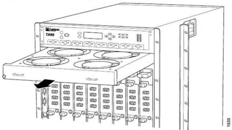
natural_image
Line drawing of a server rack unit with multiple ports and a black arrow pointing to one (no text or symbols on the device itself)Removing the T640 Craft Interface
The craft interface is hot-insertable and hot-removable. When you install the craft interface, allow several minutes for the display to reflect the current state of the T1600 router.
The craft interface is located on the front of the chassis above the FPC card cage. The craft interface weighs approximately 2 lb (0.9 kg). To remove the craft interface (see Figure 128 on page 296):
- Attach an electrostatic discharge (ESD) grounding strap to your bare wrist and connect the strap to one of the ESD points on the chassis.
- Completely loosen the screws at the four corners of the craft interface.
- Insert the blade of a flat-blade screwdriver into the slot on one side of the craft interface, then gently pry that side out from the chassis.
- Repeat Step 3 for the other side of the craft interface.
- Grasp the craft interface by the top and bottom edges and carefully pull it straight out of the chassis.
Figure 128: Removing the T640 Craft Interface

natural_image
Line drawing of a server rack unit with multiple ports and control panels (no text or symbols visible)Installing the T1600 Craft Interface
To install the T1600 craft interface (see Figure 129 on page 296):
-
Attach an electrostatic discharge (ESD) grounding strap to your bare wrist and connect the strap to one of the ESD points on the chassis.
-
Grasping the craft interface by the top and bottom edges, press it into place.
-
Tighten the screws at the corners of the craft interface.

NOTE: When you install the craft interface in an operating T1600 router, allow several minutes for the LEDs on the craft interface to reflect the current state of the T1600 router.
After you install the replacement craft interface, immediately reinstall the upper front fan tray.
Figure 129: Installing a Replacement Craft Interface
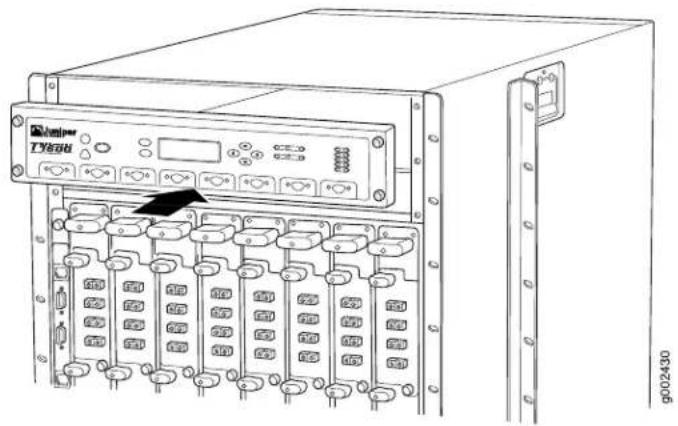
Reinstalling the T1600 Upper Front Fan Tray
To install the upper front fan tray (see Figure 130 on page 297):
- Attach an electrostatic discharge (ESD) grounding strap to your bare wrist and connect the strap to one of the ESD points on the chassis.
- Grasp the fan tray by its handles and insert it straight into the chassis.
- Tighten the captive screws on each side of the fan tray faceplate to secure it in the chassis.
Figure 130: Installing a Front Fan Tray
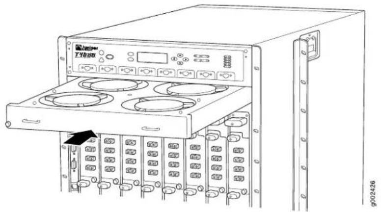
natural_image
Line drawing of a server rack unit with multiple drive bays and an open top panel (no text or symbols visible)Related Hardware Required for Upgrading from a T640 Router to a T1600 Router on page 270.
•T640 to T1600 Upgrade Kit on page 271
•Overview of Upgrading a T640 Router to a T1600 Router on page 269
•Tools Required to Upgrade a T640 Router to a T1600 Router on page 278
•Verifying the Hardware Versions Before an Upgrade to a T1600 Router on page 271
Documentation
Attaching the T1600 Agency Label
To attach the T1600 agency label:
- Locate the T640 agency label on the side of the chassis.
- Peel the protective backing off the T1600 agency label.
- Apply the T1600 agency label on top of the T640 agency label.
Related Overview of Upgrading a T640 Router to a T1600 Router on page 269. Documentation •Registering Your T1600 Upgrade on page 298
Registering Your T1600 Upgrade
You must register the T1600 upgrade with Juniper Networks upon completion of the upgrade. To register your upgrade:
- Log on to the Juniper Networks Customer Support Center at http://www.juniper.net/customers/support/.
- Click on Update Install Base.
- Follow the instructions provided in this link.
After your T1600 upgrade is registered, allow up to 45 days for restocking of the new hardware configuration to support any Next Day or Same Day contracts. Juniper Networks will provide Best Effort support until restocking of the upgraded product is complete.
PART 4
Installing and Replacing Components
- Overview of Installing and Replacing Components on page 301
- Replacing Chassis Components on page 305
- Replacing Cooling System Components on page 325
- Replacing Host Subsystem Components on page 349
- Replacing Line Card Components on page 377
- Replacing Power System Components on page 393
- Replacing Switch Fabric Components on page 449
CHAPTER 25
Overview of Installing and Replacing Components
• T1600 Field-Replaceable Units on page 301
- Tools and Parts Required for Replacing T1600 Hardware Components on page 302
T1600 Field-Replaceable Units
Field-replaceable units (FRUs) are router components that can be replaced at the customer site. Replacing most FRUs requires minimal router downtime. The router uses the following types of FRUs:
- Hot-removable and hot-insertable FRUs—You can remove and replace these components without powering off the router or disrupting the routing functions.
- Hot-pluggable FRUs—You can remove and replace these components without powering down the router, but the routing functions of the system are interrupted when the component is removed.

NOTE: Before you replace most host subsystem components, such as a control board or Routing Engine, you must take the host subsystem offline. However, it is not necessary to halt the host subsystem to insert or remove a PC card.
You must power off the Routing Engine before replacing a CompactFlash card or solid-state disk in a Routing Engine.
Table 103 on page 302 lists the FRUs for the router.
Table 103: Field-Replaceable Units
| Hot-Pluggable FRUsHot-Removable and | |
| Air filters | Connector Interface Panel (CIP) |
| Craft Interface | Nonredundant control boards (T-CB and LCC-CB) |
| Flexible PIC Concentrators (FPCs) | Master control board (T-CB or LCC-CB) (if nonstop active routing is not configured) |
| Front and rear fan trays | |
| PICs | Nonredundant Routing Engine |
| Redundant power supplies | Master Routing Engine (if nonstop active routing is not configured) |
| Master SONET Clock Generators (SCG) | Master SONET Clock Generator (SCG) |
| Switch Interface Boards (T1600-SIBs or TXP-T1600 SIBs) | Nonredundant SONET Clock Generator (SCG) |
| Backup control board (T-CB or LCC-CB) | |
| Master control board (T-CB or LCC-CB) (if nonstop active routing is configured) | |
| Backup Routing Engine | |
| Master Routing Engine (if nonstop active routing is configured) |
Related Documentation
Taking the T1600 Host Subsystem Offline on page 349.
•System Architecture Description for T Series Routers on page 6
•T1600 Chassis Description on page 19
Tools and Parts Required for Replacing T1600 Hardware Components
To replace hardware components, you need the tools and parts listed in Table 104 on page 302.
Table 104: Tools and Parts Required for Component Replacement
| Tool or partComponents | |
| All | Electrostatic discharge (ESD) grounding wrist strap |
| AC power supplyThree-phase delta AC power supply or three-phase wye AC power supply | Phillips (+) screwdrivers, number 2 to access the metal AC wiring compartment1/4-in. slotted screwdriver to attach the ground wire and input terminal wires of the AC power cord. |
| Phillips (+) screwdrivers, numbers 1 and 2Air filter (front or | |
| Phillips (+) screwdrivers, numbers 1 and 2CIP | |
| Phillips (+) screwdrivers, numbers 1 and 2Craft interface | |
| DC power supplyThree-input 240-A DC power supply, four-input 240-A DC power supply, or six-input DC power supply | Phillips (+) screwdrivers, numbers 1 and 27/16-in. (11 mm) nut driverCAUTION: You must use an appropriate torque-controlled tool to tighten the nuts. Applying excessive torque damages the terminal studs and the power supply. The absolute maximum torque that may be applied to this nut is 45 lb-in. (5.0 Nm).FlashlightNonconductive sharp object |
| DC power supply cable | 7/16-in. (11 mm) nut driverCAUTION: You must use an appropriate torque-controlled tool to tighten the nuts. Applying excessive torque damages the terminal studs and the power supply. The absolute maximum torque that may be applied to this nut is 45 lb-in. (5.0 Nm). |
| Phillips (+) screwdrivers, numbers 1 and 2Fan tray (front or | |
| FPC | Phillips (+) screwdrivers, numbers 1 and 2Blank panel (if component is not reinstalled)Electrostatic bag or antistatic mat |
| PIC | Phillips (+) screwdrivers, numbers 1 and 2Rubber safety cap for fiber-optic PICs or fiber-optic PIC cablesFlat-blade (-) screwdriver for Type 1 PICsElectrostatic bag or antistatic matBlank panel (if component is not reinstalled) |
| Routing Engine | Phillips (+) screwdrivers, numbers 1 and 2Electrostatic bag or antistatic matBlank panel (if component is not reinstalled) |
Table 104: Tools and Parts Required for Component Replacement (continued)
| Tool or partComponents | |
| Serial cable to AUXILIARY or CONSOLE Routing Engine port | Flat-blade (−) screwdriver |
| T1600-SIB | Phillips (+) screwdrivers, numbers 1 and 2Electrostatic bag or antistatic matBlank panel (if component is not reinstalled) |
| Phillips (+) screwdrivers, numbers 1 and 2SCG | |
| T-CB or LCC-CB | Phillips (+) screwdrivers, numbers 1 and 2Electrostatic bag or antistatic matBlank panel (if component is not reinstalled) |
Related Documentation
•T1600 Chassis Description on page 19
•T1600 Router Description on page 3
•Returning a Hardware Component to Juniper Networks, Inc. on page 543
CHAPTER 26
Replacing Chassis Components
- Replacing the T1600 Front Air Filter on page 305
- Replacing the T1600 Rear Air Filter on page 307
- Replacing the T1600 Alarm Relay Wires on page 310
- Replacing a T1600 Console or Auxiliary Cable on page 312
- Replacing a T1600 Management Ethernet Cable on page 315
- Replacing a T1600 CIP on page 317
- Replacing the T1600 Craft Interface on page 320
- Replacing a T1600 SCG on page 321
Replacing the T1600 Front Air Filter
- Removing the T1600 Front Air Filter on page 305
- Installing the T1600 Front Air Filter on page 306
Removing the T1600 Front Air Filter
The front air filter, located below the FPC card cage in the front of the chassis, and install horizontally. The front air filter weighs approximately 1 lb (0.5 kg). The air filters are hot-insertable and hot-removable.
To remove the front air filter (see Figure 131 on page 306):
- Attach an electrostatic discharge (ESD) grounding strap to your bare wrist, and connect the strap to one of the ESD points on the chassis.
- Unwrap any PIC cables from the spools on the cable management system, and remove the cables from the tray. Arrange the cables so that they do not block the front of the cable management system and tray, and secure them with temporary fasteners so that they are not supporting their own weight as they hang from the connector.

CAUTION: Do not let fiber-optic cable hang free from the connector. Do not allow fastened loops of cable to dangle, which stresses the cable at the fastening point.
- Simultaneously pull the two releases on the cable management system. Lift it up and outward to lock it in place to access the air filter.
- Loosen the captive screws on the corners of the air filter faceplate.
- Grasp the handles and pull the air filter straight out of the chassis.
- Remove the filter element from the air filter frame (see Figure 132 on page 306).
Figure 131: Removing the Front Air Filter

natural_image
Technical line drawing of a server rack unit with mounting brackets and a 2038 dimension label (no text or symbols on the diagram itself)Figure 132: Replacing the Front Filter Element

natural_image
Technical line drawing of a mechanical assembly with grid pattern and an upward arrow (no text or symbols)Installing the T1600 Front Air Filter
To install the front air filter (see Figure 133 on page 307):
- Attach an electrostatic discharge (ESD) grounding strap to your bare wrist, and connect the strap to one of the ESD points on the chassis.
- Insert the filter element into the air filter frame.
- Grasp the air filter by the handles on its faceplate, and slide it straight into the chassis.
- Tighten the captive screws on the corners of the faceplate.
- Unlock the cable management system, and lower it to the fully lowered position.
- Rearrange the PIC cables in the cable management system.
Figure 133: Installing the Front Air Filter
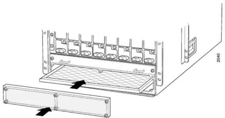
natural_image
Technical line drawing of a server rack with mesh panel and mounting bracket (no text or symbols)Related Documentation
T1600 Preventing Electrostatic Discharge Damage on page 552.
•T1600 Cooling System Description on page 37
•Troubleshooting the T1600 Cooling System on page 507
•Clearance Requirements for Airflow and T1600 Hardware Maintenance on page 135
•Maintaining the T1600 Air Filters on page 476
Replacing the T1600 Rear Air Filter
-
Removing a Rear T1600 Air Filter on page 307
-
Installing the T1600 Rear Air Filter on page 309
Removing a Rear T1600 Air Filter
The rear air filter is located at the left rear edge of the chassis. The rear air filter weighs less than 1 lb (0.5 kg).
To remove the rear air filter:
-
Attach an electrostatic discharge (ESD) grounding strap to your bare wrist, and connect the strap to one of the ESD points on the chassis.
-
Loosen the captive screws at the top, center, and bottom of the air filter, using a Phillips (+) screwdriver, number 2.
-
Grasp the air filter cover by the captive screws, and pull firmly to remove the cover and honeycomb assembly from the chassis (see Figure 134 on page 308).
-
Press the filter element inward until it clears the hooks at the top and bottom of the air filter slot, then push it to the left to unseat it.
-
Move the tabs on the filter element to a horizontal position.
-
Grasp the tabs on the filter element and carefully pull it straight out from the chassis (see Figure 135 on page 309).
Figure 134: Removing the Rear Air Filter
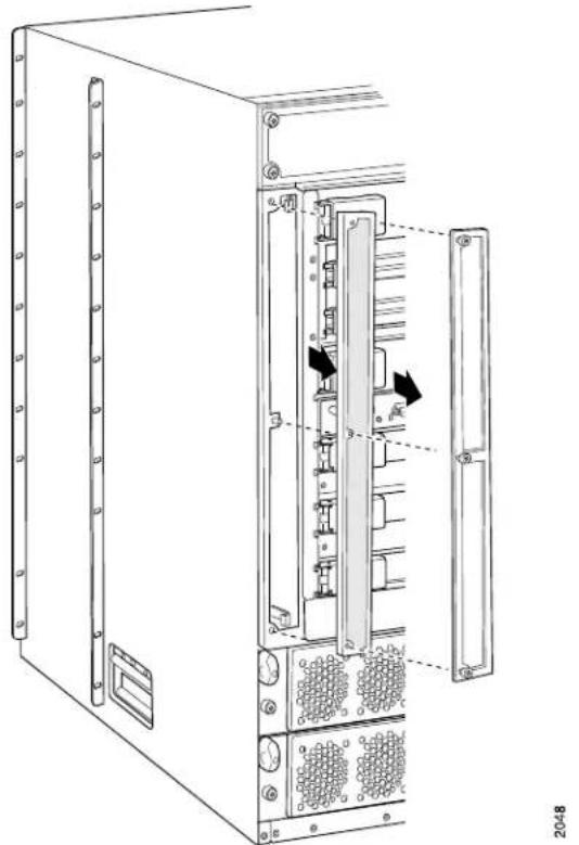
natural_image
Technical line drawing of a server rack cabinet with internal components and mounting holes (no text or symbols)Figure 135: Removing the Rear Air Filter Element
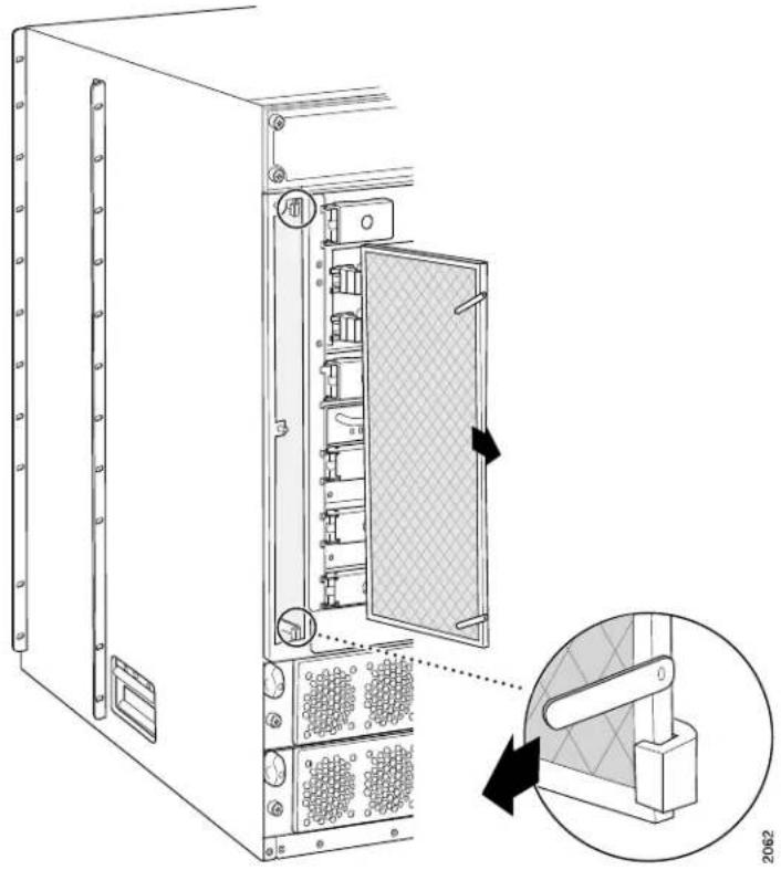
natural_image
Technical line drawing of a server rack cabinet with internal components and a close-up inset showing a mechanical clamp mechanism (no text or symbols)Installing the T1600 Rear Air Filter
To install the rear air filter (see Figure 136 on page 310):
- Attach an electrostatic discharge (ESD) grounding strap to your bare wrist, and connect the strap to one of the ESD points on the chassis.
- Holding the filter by the tabs, carefully push the filter all the way into the air filter slot.
- Holding the filter all the way in, push it to the right side of the slot until it is held in place behind the hooks.
- Move the tabs to a vertical position.
- Place the right edge of the honeycomb against the flange of the air filter slot.
- Line up the holes at the top, center, and bottom of the honeycomb with the pins in the slot, and press the honeycomb into place.
- Replace the air filter cover.
- Firmly tighten the captive screws at the top, center, and bottom of the filter cover to secure it to the chassis, using a Phillips (+) screwdriver, number 2.
Figure 136: Installing the Rear Air Filter

Replacing the T1600 Alarm Relay Wires
- Removing the T1600 Alarm Relay Wires on page 310
- Installing the T1600 Alarm Relay Wires on page 312
Removing the T1600 Alarm Relay Wires
To remove the wires connected to an alarm-reporting device:
- Disconnect the existing wire at the external device.
- Attach an electrostatic discharge (ESD) grounding strap to your bare wrist, and connect the strap to one of the ESD points on the chassis.
- Using a 2.5-mm flat-blade screwdriver, loosen the small screws on the face of the terminal block and remove the block from the relay contact.
- Using the 2.5-mm flat-blade screwdriver, loosen the small screws on the side of the terminal block. Remove existing wires from the slots in the front of the block.
Figure 137: CIP

Figure 138: Alarm Relay Contacts on the CIP
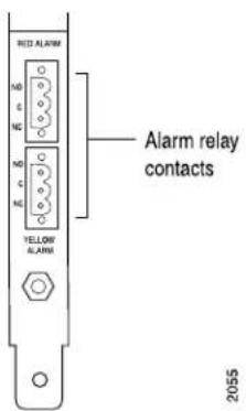
Installing the T1600 Alarm Relay Wires
To connect the router to external alarm-reporting devices, attach wires to the RED ALARM and YELLOW ALARM relay contacts on the CIP. A system condition that triggers the red or yellow alarm LED on the craft interface also activates the corresponding alarm relay contact.
The terminal blocks that plug into the alarm relay contacts are supplied with the router. They accept wire of any gauge between 28 AWG and 14 AWG (0.08 and 2.08 mm which is not provided. Use the gauge of wire appropriate for the external device you are connecting.
To connect the wires to an alarm-reporting device::
- Prepare the required length of replacement wire with gauge between 28 AWG and 14 AWG (0.08 and 2.08 mm
- Attach an electrostatic discharge (ESD) grounding strap to your bare wrist, and connect the strap to one of the ESD points on the chassis.
- Insert the replacement wires into the slots in the front of the block. Using a 2.5-mm flat-blade screwdriver, tighten the screws to secure the wire.
- Plug the terminal block into the relay contact and use a 2.5-mm flat-blade screwdriver to tighten the screws on the face of the block.
- Attach the other end of the wires to the external device.
Replacing a T1600 Console or Auxiliary Cable
To replace a serial cable connected to a management console or auxiliary device:
- Removing a T1600 Console or Auxiliary Cable on page 313
- Installing a T1600 Console or Auxiliary Cable on page 315
Removing a T1600 Console or Auxiliary Cable
To remove a serial cable connected to a management console or auxiliary device (see Figure 139 on page 314):
- Attach an electrostatic discharge (ESD) grounding strap to your bare wrist, and connect the strap to one of the site ESD points on the chassis.
- Turn off the power to the console or auxiliary device.
- Unscrew the screws that secure the cable connector to the port, using a 2.5-mm flat-blade screwdriver if necessary.
- Pull the cable connector straight out of the port.
- Disconnect the cable from the console or auxiliary device.
Figure 139: DB-9 Port on the CIP

Installing a T1600 Console or Auxiliary Cable
The AUXILIARY port and CONSOLE port on the CIP both accept an RS-232 (EIA-232_ serial cable with DB-9 connectors.
To connect a management console or auxiliary device:
- Attach an electrostatic discharge (ESD) grounding strap to your bare wrist, and connect the strap to one of the site ESD points on the chassis.
- Connect one end of the replacement cable into the appropriate CONSOLE or AUXILIARY port. The ports labeled HOST 0 connect to the Routing Engine in the upper Routing Engine slot (RE0), and the ports labeled HOST 1 connect to the Routing Engine in the lower Routing Engine slot (RE1).
- Using a 2.5-mm flat-blade screwdriver, tighten the screws on the connector.
- Plug the other end of the cable into the device's serial port.
Related Documentation
T1600 Connector Interface Panel (CIP) Description on page 25.
- Connecting the T1600 Router to a Management Console or Auxiliary Device on page 232
•T1600 Routing Engine Interface Cable and Wire Specifications on page 167
•T1600 DB-9 Connector Pinouts for the Routing Engine AUXILIARY and CONSOLE Ports on page 168
•T1600 Preventing Electrostatic Discharge Damage on page 552
Replacing a T1600 Management Ethernet Cable
- Removing a T1600 Management Ethernet Cable on page 315
- Installing a T1600 Management Ethernet Cable on page 316
Removing a T1600 Management Ethernet Cable
- Press the tab on the connector and pull the connector straight out of the ETHERNET port. Figure 140 on page 315 shows the connector.
- Disconnect the cable from the network device.
Figure 140: Ethernet Cable Connectors

9003781
Figure 141: Ethernet Port on CIP

Installing a T1600 Management Ethernet Cable
- Plug one end of the replacement cable into the appropriate ETHERNET port. The ports labeled HOST 0 connect to the Routing Engine in the upper Routing Engine slot (RE0), and the ports labeled HOST 1 connect to the Routing Engine in the lower Routing Engine slot (RE1).
- Plug the other end of the cable into the network device.
Related Documentation
T1600 Connector Interface Panel (CIP) Description on page 25.
•Connecting the T1600 Router to a Network for Out-of-Band Management on page 234
•T1600 Routing Engine Interface Cable and Wire Specifications on page 167
•T1600 RJ-45 Connector Pinouts for the Routing Engine ETHERNET Port on page 168
Replacing a T1600 CIP
- Removing a T1600 CIP on page 317
- Installing a T1600 CIP on page 318
Removing a T1600 CIP
The CIP is located to the left side of the FPC card cage. It houses the Routing Engine interface ports, which accept connections to external management and alarm-reporting devices.
The CIP is hot-pluggable. It weighs approximately 8 lb (3.6 kg). When the CIP is removed, you cannot control or communicate with the router using an external device.
To remove the CIP (see Figure 142 on page 318):
- Attach an electrostatic discharge (ESD) grounding strap to your bare wrist, and connect the strap to one of the site ESD points on the chassis.
- Disconnect any external devices connected to the CIP.
- Loosen the captive screws at the top and bottom of the CIP faceplate.
- Grasp the handle on the CIP faceplate and carefully pull the CIP straight out of the chassis.

CAUTION: Be sure to slide the CIP straight within the slot to avoid damaging the connector pins on the front of the midplane.
Figure 142: Removing the CIP

natural_image
Technical line drawing of a server rack unit with open door and internal compartments (no text or symbols)Installing a T1600 CIP
To install the CIP (see Figure 143 on page 319):
- Attach an electrostatic discharge (ESD) grounding strap to your bare wrist, and connect the strap to one of the ESD points on the chassis.
- Grasp the CIP handle with one hand and hold the bottom edge of the CIP with the other hand to support its weight.

NOTE: The componentson the CIP are on the left side of the board, unlike the components of an FPC, which are on the right side. Verify that the components are on the left before inserting the CIP.
-
Insert the CIP into the leftmost slot of the FPC card cage, carefully aligning the top and bottom of the CIP with the guides in the card cage.
-
Carefully push the CIP straight into the chassis until it contacts the midplane.
- Tighten the screws at the top and bottom of the CIP faceplate.
- Reattach any external devices connected to the CIP.

CAUTION: Be sure to slide the CIP straight within the slot to avoid damaging the connector pins on the front of the midplane.
- To verify that the CIP is installed correctly, plug an Ethernet cable into the Ethernet port on the CIP. If the host module is operational, the ACTIVE LED blinks to indicate Ethernet activity. If you can run the CLI, the CIP is installed correctly.
Figure 143: Installing a CIP
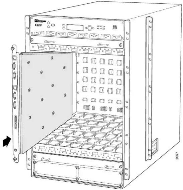
natural_image
Line drawing of a rack-mounted server unit with open panel and internal compartments (no text or symbols)Related Documentation
T1600 Preventing Electrostatic Discharge Damage on page 552.
•T1600 Routing Engine Interface Cable and Wire Specifications on page 167
- Maintaining the T1600 Routing Engines on page 486
•Overview of Connecting the T1600 Router to External Devices on page 231
Replacing the T1600 Craft Interface
The craft interface is located on the front of the chassis above the FPC card cage (see Figure 144 on page 320). The craft interface is hot-insertable and hot-removable. When you install the craft interface, allow several minutes for the display to reflect the current state of the router.
- Removing the T1600 Craft Interface on page 320
- Installing the T1600 Craft Interface on page 320
Removing the T1600 Craft Interface
Before you remove the craft interface, remove the front upper fan tray. To remove the craft interface, see Figure 144 on page 320.
- Attach an electrostatic discharge (ESD) grounding strap to your bare wrist, and connect the strap to one of the ESD points on the chassis.
- Completely loosen the screws at the four corners of the craft interface.
- Insert the blade of a flat-blade screwdriver into the slot on one side of the craft interface, then gently pry that side out from the chassis.
- Insert the blade of a flat-blade screwdriver into the slot on the other side of the craft interface, then gently pry that side out from the chassis.
- Grasp the craft interface by the top and bottom edges and carefully pull it straight out of the chassis.
Figure 144: Removing the Craft Interface

natural_image
Technical line drawing of a server rack unit with multiple ports and control panel (no text or symbols)Installing the T1600 Craft Interface
To install the craft interface (see Figure 145 on page 321):
-
Attach an electrostatic discharge (ESD) grounding strap to your bare wrist, and connect the strap to one of the ESD points on the chassis.
-
Grasping the craft interface by the top and bottom edges, press it into place.
-
Tighten the screws at the corners of the craft interface.

NOTE: When you install the craft interface in an operating router, allow several minutes for the LEDs on the craft interface to reflect the current state of the router.
After you install the replacement craft interface, immediately reinstall the upper front fan tray.
Figure 145: Installing a Replacement Craft Interface

Related Documentation
T1600 Craft Interface Description on page 31.
•T1600 Craft Interface Alarm LEDs and ACO/LT Button on page 33
Replacing a T1600 SCG
- Removing a T1600 SCG on page 321
- Installing the T1600 SCG on page 322
Removing a T1600 SCG
The router can have one or two SCGs installed. The SCGs are located in the upper rear of the chassis, above the control boards and Routing Engines. Each SCG weighs approximately 1.9 lb (0.9 kg).
A nonredundant SCG is hot-pluggable. For redundant SCGs, the master SCG is hot-pluggable. The backup SCG is hot-removable and hot-insertable if the master SCG is functioning. Removing the backup SCG does not affect the functioning of the router. Taking the master SCG offline might result in a brief loss of SONET clock lock while the backup SCG becomes the master.
To remove an SCG (see Figure 146 on page 322):
- Place an electrostatic bag or antistatic mat on a flat, stable surface.
- Attach an electrostatic discharge (ESD) grounding strap to your bare wrist, and connect the strap to one of the ESD points on the chassis.
- Press the online/offline button on the SCG faceplate and hold it down until the LED goes out (about 5 seconds).
- Loosen the captive screws on the edges of the SCG faceplate.
- Grasp the SCG by the handle on the faceplate and slide it out of the chassis.
- Place the SCG on the antistatic mat.
Figure 146: Removing an SCG

natural_image
Technical line drawing of a computer rack unit with internal components and mounting holes (no text or symbols)Installing the T1600 SCG
To install a replacement SCG (see Figure 147 on page 323):
- Attach an electrostatic discharge (ESD) grounding strap to your bare wrist, and connect the strap to one of the ESD points on the chassis.
- Carefully align the sides of the SCG with the guides in the SCG slot.
- Grasp the SCG by its handle and slide it straight into the chassis until it contacts the midplane.
- Tighten the captive screws on the corners of the SCG faceplate.
- To bring the SCG online, press the online/offline button until the green OK LED lights.
- To verify that the SCG is installed correctly and is functioning normally, check the LEDs on the SCG faceplate. The green OK LED should light steadily. If the SCG is master, the blue MASTER LED should also light steadily.
To check the status of the SCGs, use the following CLI command:
user@host> show chassis environment scg
For more information about using the CLI, see the Junos OS manuals.
Figure 147: Installing an SCG

natural_image
Technical line drawing of a server rack with an attached drive unit and mounting bracket (no text or symbols)Related Documentation
•Maintaining the T1600 SCGs on page 495
•T1600 SONET Clock Generators Description on page 28
CHAPTER 27
Replacing Cooling System Components
- Replacing the T1600 Standard Lower Front Fan Tray on page 325
- Replacing the T1600 Standard Upper Front Fan Tray on page 326
- Replacing the T1600 Rear Fan Tray on page 328
- Upgrading to the T1600 Quiet Fan Trays on page 330
- Replacing the T1600 Quiet Lower Front Fan Tray on page 337
- Replacing the T1600 Quiet Upper Front Fan Tray on page 339
- Replacing the T1600 Quiet Rear Fan Tray on page 341
- Replacing the T1600 Lower Front Fan Tray (FANTRAY-T4000) on page 344
- Replacing the T1600 Upper Front Fan Tray (FANTRAY-T4000) on page 346
Replacing the T1600 Standard Lower Front Fan Tray
The lower front fan tray is located below the front air filter. Each standard front fan tray weighs about 18.6 lb (8.4 kg). The fan trays are hot-insertable and hot-removable. The standard upper and lower fan trays are interchangeable with each other.
- Removing the T1600 Standard Lower Front Fan Tray on page 325
- Installing the T1600 Standard Lower Front Fan Tray on page 326
Removing the T1600 Standard Lower Front Fan Tray
- Attach an electrostatic discharge (ESD) grounding strap to your wrist, and connect the strap to one of the ESD points on the chassis.
- Unwrap any PIC cables from the spools on the front cable management system and remove the cables from the tray. Arrange the cables so that they do not block the front cable management system and tray, and secure them with temporary fasteners so that they are not supporting their own weight as they hang from the connector.

CAUTION: Do not let fiber-optic cable hang free from the connector. Do not allow fastened loops of cable to dangle, which stresses the cable at the fastening point.
- Simultaneously pull the two releases on the front cable management system. Lift it up and outward to lock it in place to access the lower fan tray.
- Rearrange the PIC cables in the front cable management system. For more information about proper cable arrangement, see “Maintaining T1600 PICs and PIC Cables” on page 488.
- Loosen the captive screws on the corners of the fan tray faceplate.
- Grasp the handles and pull the fan tray halfway out of the chassis.

WARNING: To avoid injury, keep tools and your fingers away from the fans asyouslide the fan tray out of the chassis. The fans might still be spinning.
- When the fans stop spinning, place one hand under the fan tray to support it and pull the fan tray completely out of the chassis.
Installing the T1600 Standard Lower Front Fan Tray
To install a standard lower front fan tray:
- Attach an electrostatic discharge (ESD) grounding strap to your bare wrist, and connect the strap to one of the ESD points on the chassis.
- Grasp the fan tray by its handles and insert it straight into the chassis.
- Tighten the captive screws on each side of the fan tray faceplate to secure it in the chassis.
- Unlock the front cable management system and lower it to the fully lowered position.
- Rearrange the PIC cables in the front cable management system. For more information about proper cable arrangement, see "Maintaining T1600 PICs and PIC Cables" on page 488.
Related Documentation
T1600 Cooling System Description on page 37.
•Troubleshooting the T1600 Cooling System on page 507
•Clearance Requirements for Airflow and T1600 Hardware Maintenance on page 135
•Maintaining the T1600 Fan Trays on page 478
•T1600 Preventing Electrostatic Discharge Damage on page 552
Replacing the T1600 Standard Upper Front Fan Tray
The upper front fan tray is located above the FPC card cage. Each standard front fan tray weighs about 18.6 lb (8.4 kg). The fan trays are hot-insertable and hot-removable. The standard upper and lower fan trays are interchangeable with each other.
- Removing the T1600 Standard Upper Front Fan Tray on page 327
- Installing the T1600 Standard Upper Front Fan Tray on page 327
Removing the T1600 Standard Upper Front Fan Tray
To remove a standard upper front fan tray (see Figure 148 on page 327):
- Attach an electrostatic discharge (ESD) grounding strap to your bare wrist, and connect the strap to one of the ESD points on the chassis.
- Loosen the captive screws on the corners of the fan tray faceplate.
- Grasp the handles and pull the fan tray halfway out of the chassis.

WARNING: To avoid injury, keep tools and your fingers away from the fans asyouslide the fan trayout of the chassis. The fans might still be spinning.
- When the fans stop spinning, place one hand under the fan tray to support it and pull the fan tray completely out of the chassis.
Figure 148: Removing a Standard Upper Front Fan Tray
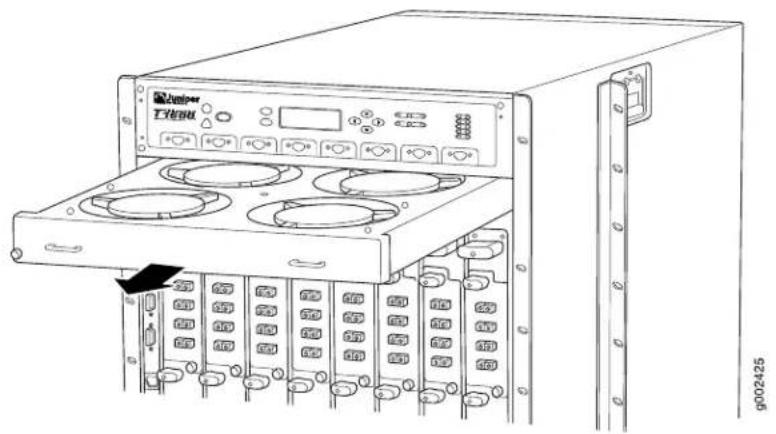
natural_image
Line drawing of a server rack unit with multiple drive bays and an external control panel (no text or symbols visible)Installing the T1600 Standard Upper Front Fan Tray
To install a standard upper front fan tray (see Figure 149 on page 328):
- Attach an electrostatic discharge (ESD) grounding strap to your bare wrist, and connect the strap to one of the ESD points on the chassis.
- Grasp the fan tray by its handles and insert it straight into the chassis.
- Tighten the captive screws on each side of the fan tray faceplate to secure it in the chassis.
Figure 149: Installing an Upper Front Fan Tray
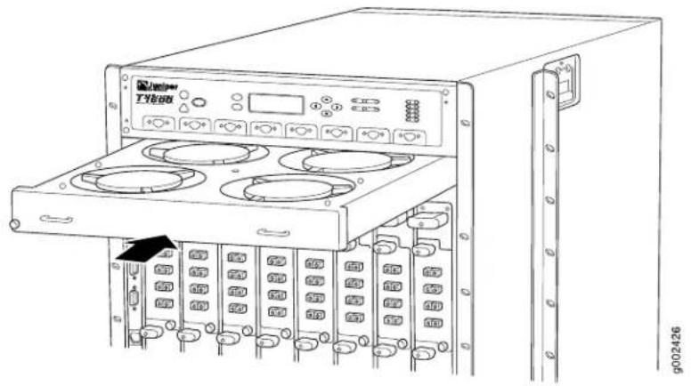
natural_image
Line drawing of a server rack unit with multiple drive bays and an open top panel (no text or symbols visible)Related Documentation
T1600 Cooling System Description on page 37.
•Troubleshooting the T1600 Cooling System on page 507
•Clearance Requirements for Airflow and T1600 Hardware Maintenance on page 135
•Maintaining the T1600 Fan Trays on page 478
Replacing the T1600 Rear Fan Tray
The rear fan tray is mounted vertically on the right side of the rear of the chassis. The rear fan tray contains eight fans, and is not interchangeable with the front fan trays. The FAN-REAR-TX-T640 rear fan tray weighs about 10 lb (4.5 kg). The FAN-REAR-TXP-LCC rear fan tray weighs about 10 lb (4.5 kg). The FAN-R-TXP-3D-LCC rear fan tray weighs about 13 lb (5.9 kg).
- Removing the T1600 Rear Fan Tray on page 328
- Installing the T1600 Rear Fan Tray on page 329
Removing the T1600 Rear Fan Tray

CAUTION: To maintain proper cooling, do not operate the router with the rear fan tray removed for more than 1 minute.
To remove the rear fan tray (see Figure 150 on page 329):
- Attach an electrostatic discharge (ESD) grounding strap to your bare wrist, and connect the strap to an approved site ESD grounding point.
- Loosen the captive screws on the top and bottom of the fan tray faceplate.
-
Grasp the handles, and pull the fan tray halfway out of the chassis.
-
Wait for the fans to stop spinning.
- After the fans stop spinning, place one hand under the fan tray to support it, and pull the fan tray completely out of the chassis.
Figure 150: Removing the Rear Fan Tray

Installing the T1600 Rear Fan Tray
To install a replacement rear fan tray (see Figure 151 on page 330):
- Attach an electrostatic discharge (ESD) grounding strap to your bare wrist, and connect the strap to one of the ESD points on the chassis.
- Grasp the fan tray by its handles and insert it straight into the chassis.
- Tighten the captive screws on the fan tray faceplate to secure it in the chassis, using a Phillips (+) screwdriver, number 2.
Figure 151: Installing the Rear Fan Tray

natural_image
Technical line drawing of a server rack cabinet with internal components and ventilation fans (no text or labels)Related Documentation
T1600 Cooling System Description on page 37.
•Clearance Requirements for Airflow and T1600 Hardware Maintenance on page 135
•Maintaining the T1600 Fan Trays on page 478
•Troubleshooting the T1600 Cooling System on page 507
•T1600 Preventing Electrostatic Discharge Damage on page 552
Upgrading to the T1600 Quiet Fan Trays
- Upgrading the Standard Lower Front Fan Tray to a Quiet Lower Front Fan Tray on page 331
- Removing the Standard Upper Front Fan Tray on page 332
-
Removing the Craft Interface on page 333
-
Installing the Air Deflector and Craft Interface on page 334
- Installing the Quiet Upper Front Fan Tray on page 334
- Upgrading the Standard Rear Fan Tray to a Quiet Rear Fan Tray on page 335
Upgrading the Standard Lower Front Fan Tray to a Quiet Lower Front Fan Tray
Each standard front fan tray weighs about 18.6 lb (8.4 kg). Each quiet front fan tray weighs about 17.8 lb (8.1 kg).
- Attach an electrostatic discharge (ESD) grounding strap to your wrist, and connect the strap to one of the ESD points on the chassis.
- Unwrap any PIC cables from the spools on the front cable management system and remove the cables from the tray. Arrange the cables so that they do not block the front cable management system and tray, and secure them with temporary fasteners so that they are not supporting their own weight as they hang from the connector.

CAUTION: Do not let fiber-optic cable hang free from the connector. Do not allow fastened loops of cable to dangle, which stresses the cable at the fastening point.
- Simultaneously pull the two releases on the front cable management system. Lift it up and outward to lock it in place to access the lower fan tray.
- Rearrange the PIC cables in the front cable management system. For more information about proper cable arrangement, see "Maintaining T1600 PICs and PIC Cables" on page 488.
- Loosen the captive screws on the corners of the standard lower front fan tray faceplate.
- Grasp the handles and pull the standard lower front fan tray halfway out of the chassis.

WARNING: To avoid injury, keep tools and your fingers away from the fans asyouslide the fan tray out of the chassis. The fans might still be spinning.
- Wait for the fans to stop spinning.
- After the fans stop spinning, place one hand under the standard lower front fan tray to support it and pull the fan tray completely out of the chassis.
- Locate the fan tray labeled FAN-T-FBOT-S LOWER FANTRAY.
- Press the two latches located on each side of the quiet lower front fan tray up, and insert the quiet lower front fan tray straight into the lower front fan tray slot. See Figure 152 on page 332
-
Tighten the captive screws on each side of the quiet lower front fan tray faceplate to secure it in the chassis.
-
Unlock the front cable management system and lower it to the fully lowered position.
- Rearrange the PIC cables in the front cable management system. For more information about proper cable arrangement, see "Maintaining T1600 PICs and PIC Cables" on page 488.
Figure 152: Installing a Quiet Lower Front Fan Tray

Removing the Standard Upper Front Fan Tray
The upper front fan tray is located above the FPC card cage. Each standard front fan tray weighs about 18.6 lb (8.4 kg). The fan trays are hot-removable.
To remove a standard upper front fan tray (see Figure 153 on page 333):
- Attach an electrostatic discharge (ESD) grounding strap to your bare wrist, and connect the strap to one of the ESD points on the chassis.
- Loosen the captive screws on the corners of the fan tray faceplate.
- Grasp the handles and pull the fan tray halfway out of the chassis.

WARNING: To avoid injury, keep tools and your fingers away from the fans as you slide the fan trayout of the chassis. The fans might still be spinning.
- Wait for the fans to stop spinning.
- After the fans stop spinning, place one hand under the fan tray to support it and pull the fan tray completely out of the chassis.
Figure 153: Removing a Standard Upper Front Fan Tray
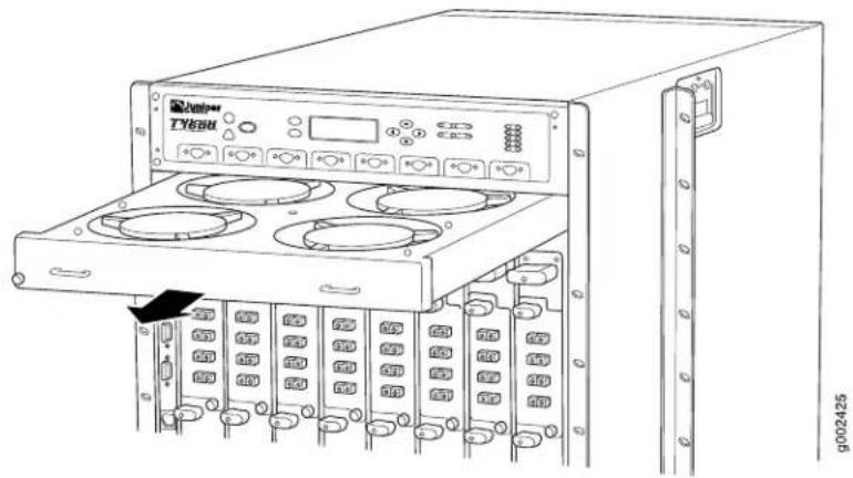
natural_image
Line drawing of an audio workstation rack with multiple drive bays and a control panel (no text or symbols visible)Removing the Craft Interface
The craft interface is located on the front of the chassis above the FPC card cage. The craft interface is hot-removable. To remove the craft interface (see Figure 154 on page 333):
- Attach an electrostatic discharge (ESD) grounding strap to your bare wrist, and connect the strap to one of the ESD points on the chassis.
- Completely loosen the screws at the four corners of the craft interface.
- Insert the blade of a flat-blade screwdriver into the slot on one side of the craft interface, then gently pry that side out from the chassis.
- Insert the blade of a flat-blade screwdriver into the slot on the other side of the craft interface, then gently pry that side out from the chassis.
- Grasp the craft interface by the top and bottom edges and carefully pull it straight out of the chassis.
- Remove the Craft Interface Panel by loosening the four fasteners.
Figure 154: Removing the Craft Interface

natural_image
Technical line drawing of a rack-mounted server unit with multiple drive bays and a central control panel (no text or symbols)Installing the Air Deflector and Craft Interface

NOTE: If an air deflector is already installed, installing another air deflector is not required.
To install the T1600 air deflector:
- Slide in the air deflector. See Figure 155 on page 334 for proper orientation of air deflector. Four holes align with the four standoffs used for mounting the craft interface.
- Replace the craft interface and secure with the four fasteners.
Figure 155: Installing the Air Deflector

Installing the Quiet Upper Front Fan Tray
The upper front fan tray is located above the FPC card cage. Each quiet front fan tray weighs about 17.8 lb (8.1 kg). The fan trays are hot-insertable. The quiet upper and lower fan trays are not interchangeable with each other. The quiet upper front fan tray is labeled FAN-T-FTOP-S UPPER FANTRAY.
To install a quiet upper front fan tray (see Figure 156 on page 335):
- Attach an electrostatic discharge (ESD) grounding strap to your bare wrist, and connect the strap to one of the ESD points on the chassis.
- Locate the fan tray labeled FAN-T-FTOP-S UPPER FANTRAY.
- Press the two latches located on each side of the quiet upper front fan tray up, and insert the quiet upper front fan tray straight into the upper front fan tray slot.
- Tighten the captive screws on each side of the fan tray faceplate to secure it in the chassis.
Figure 156: Installing the Quiet Upper Front Fan Tray

Upgrading the Standard Rear Fan Tray to a Quiet Rear Fan Tray

CAUTION: To maintain proper cooling, do not operate the router with the rear fan tray removed for more than 1 minute.
To upgrade the rear fan tray (see Figure 157 on page 336) and Figure 158 on page 337:
- Attach an electrostatic discharge (ESD) grounding strap to your bare wrist, and connect the strap to one of the ESD points on the chassis.
- Loosen the captive screws on the top and bottom of the standard fan tray faceplate.
- Grasp the handles on the faceplate, and pull the standard rear fan tray halfway out of the chassis.

WARNING: To avoid injury, keep tools and your fingers away from the fans asyouslide the fan trayout of thechassis. Thefansmight still be spinning.
- After the fans stop spinning, place one hand under the fan tray to support it, and pull the standard fan tray completely out of the chassis.
- Locate the quiet rear fan tray labeled REAR FANTRAY FAN-R-S.
- Grasp the quiet rear fan tray by its handles and insert it straight into the chassis.
- Tighten the captive screws on the quiet rear fan tray faceplate to secure it in the chassis, using a Phillips (+) screwdriver, number 2.
Figure 157: Removing the Standard Rear Fan Tray

Figure 158: Installing the Quiet Rear Fan Tray

Related Documentation
T1600 Cooling System Description on page 37. •T1600 Preventing Electrostatic Discharge Damage on page 552
Replacing the T1600 Quiet Lower Front Fan Tray
The lower front fan tray is located below the front air filter. Each quiet front fan tray weighs about 17.8 lb (8.1 kg). The fan trays are hot-insertable and hot-removable. The quiet upper and lower fan trays are not interchangeable with each other. The quiet lower front fan tray is labeled FAN-T-FBOT-S LOWER FANTRAY.
-
Removing the T1600 Quiet Lower Front Fan Tray on page 338
-
Installing the T1600 Quiet Lower Front Fan Tray on page 339
Removing the T1600 Quiet Lower Front Fan Tray
To remove the quiet lower front fan tray:
- Attach an electrostatic discharge (ESD) grounding strap to your wrist, and connect the strap to one of the ESD points on the chassis.
- Unwrap any PIC cables from the spools on the front cable management system and remove the cables from the tray. Arrange the cables so that they do not block the front cable management system and tray, and secure them with temporary fasteners so that they are not supporting their own weight as they hang from the connector.

CAUTION: Do not let fiber-optic cable hang free from the connector. Do not allow fastened loops of cable to dangle, which stresses the cable at the fastening point.
-
Simultaneously pull the two releases on the front cable management system. Lift it up and outward to lock it in place to access the lower fan tray.
-
Rearrange the PIC cables in the front cable management system. For more information about proper cable arrangement, see “Maintaining T1600 PICs and PIC Cables” on page 488.
-
Loosen the captive screws on the corners of the fan tray faceplate.
-
Grasp the handles on the faceplate, and pull the fan tray out of the chassis approximately 1 to 3 inches.

WARNING: To avoid injury, keep tools and your fingers away from the fans asyouslide the fan tray out of the chassis. The fans might still be spinning.
- Wait for all fans to stop spinning.

WARNING: Rotating blades can cause serious injury. Allow fan blades to stop before you remove the fan tray.
-
After the fans stop spinning, press up on the two latches located on each side of the fan tray to release the fan tray from the chassis (see Figure 159 on page 339).
-
Place one hand under the fan tray to support it and pull the fan tray completely out of the chassis.
Figure 159: Removing the Quiet Lower Front Fan Tray
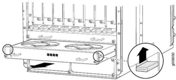
Installing the T1600 Quiet Lower Front Fan Tray
To install a quiet lower front fan tray see Figure 160 on page 339:
- Attach an electrostatic discharge (ESD) grounding strap to your bare wrist, and connect the strap to one of the ESD points on the chassis.
- Locate a replacement quiet lower fan tray labeled FAN-T-FBOT-S LOWER FANTRAY.
- Press the two latches located on each side of the quiet lower front fan tray up, and insert the quiet lower front fan tray straight into the lower front fan tray slot.
- Tighten the captive screws on each side of the quiet lower front fan tray faceplate to secure it to the chassis.
- Unlock the front cable management system and lower it to the fully lowered position.
- Rearrange the PIC cables in the front cable management system. For more information about proper cable arrangement, see "Maintaining T1600 PICs and PIC Cables" on page 488.
Figure 160: Installing the Quiet Lower Front Fan Tray

Replacing the T1600 Quiet Upper Front Fan Tray
The upper front fan tray is located above the FPC card cage. Each quiet front fan tray weighs about 17.8 lb (8.1 kg). The fan trays are hot-insertable and hot-removable. The
quiet upper and lower fan trays are not interchangeable with each other. The quiet upper front fan tray is labeled FAN-T-FTOP-S UPPER FANTRAY.
- Removing the Quiet Upper Front Fan Tray on page 340
- Installing the Quiet Upper Front Fan Tray on page 341
Removing the Quiet Upper Front Fan Tray
To remove a quiet upper front fan tray (see Figure 161 on page 340):
- Attach an electrostatic discharge (ESD) grounding strap to your bare wrist, and connect the strap to one of the ESD points on the chassis.
- Loosen the captive screws on the corners of the fan tray faceplate.
- Grasp the handles on the faceplate, and pull the fan tray out of the chassis approximately 1 to 3 inches.

WARNING: To avoid injury, keep tools and your fingers away from the fans as you slide the fan tray out of the chassis. The fans might still be spinning.
- Wait for all fans to stop spinning.

WARNING: Rotating blades can cause serious injury. Allow fan blades to stop before you remove the fan tray.
- After the fans stop spinning, press up on the two latches located on each side of the fan tray to release the fan tray from the chassis (see Figure 161 on page 340.
- Place one hand under the fan tray to support it and pull the fan tray completely out of the chassis.
Figure 161: Removing the Quiet Upper Front Fan Tray

Installing the Quiet Upper Front Fan Tray
To install a quiet upper front fan tray (see Figure 162 on page 341):
- Attach an electrostatic discharge (ESD) grounding strap to your bare wrist, and connect the strap to one of the ESD points on the chassis.
- Locate a quiet upper front fan tray labeled FAN-T-FTOP-S UPPER FANTRAY.
- Press the two latches located on each side of the quiet upper front fan tray up, and insert the quiet upper front fan tray straight into the upper front fan tray slot.
- Tighten the captive screws on each side of the fan tray faceplate to secure it in the chassis.
Figure 162: Installing the Quiet Upper Front Fan Tray

Replacing the T1600 Quiet Rear Fan Tray
The rear fan tray is mounted vertically on the right side of the rear of the chassis. The quiet rear fan tray contains eight fans, and is not interchangeable with the front fan trays. The quiet rear fan tray must be used in conjunction with the quiet front fan trays. The quiet rear fan tray weighs about 10 lb (4.5 kg).
- Removing the Quiet Rear Fan Tray on page 342
- Installing the Quiet Rear Fan Tray on page 343
Removing the Quiet Rear Fan Tray

CAUTION: To maintain proper cooling, do not operate the router with the rear fan tray removed for more than 1 minute.
To remove the quiet rear fan tray (see Figure 163 on page 343):
- Attach an electrostatic discharge (ESD) grounding strap to your bare wrist, and connect the strap to an approved site ESD grounding point.
- Loosen the captive screws on the top and bottom of the fan tray faceplate.
- Grasp the handles on the faceplate, and pull the fan tray halfway out of the chassis.

WARNING: To avoid injury, keep tools and your fingers away from the fans asyouslide the fan trayout of the chassis. The fans might still bespinning.
-
Wait for all fans to stop spinning.
-
After the fans stop spinning, place one hand under the fan tray to support it, and pull the fan tray completely out of the chassis.
Figure 163: Removing the Quiet Rear Fan Tray

Installing the Quiet Rear Fan Tray
To install a replacement quiet rear fan tray (see Figure 164 on page 344):
- Attach an electrostatic discharge (ESD) grounding strap to your bare wrist, and connect the strap to one of the ESD points on the chassis.
- Locate a replacement quiet rear fan tray labeled REAR FANTRAY FAN-R-S.
- Grasp the fan tray by its handles and insert it straight into the chassis.
- Tighten the captive screws on the fan tray faceplate to secure it in the chassis, using a Phillips (+) screwdriver, number 2.
Figure 164: Installing the Quiet Rear Fan Tray

Replacing the T1600 Lower Front Fan Tray (FANTRAY-T4000)
The lower front fan tray is located below the front air filter. Each front fan tray weighs about 20.4 lb (9.3 kg). The fan trays are hot-insertable and hot-removable. The upper and lower fan trays are interchangeable with each other.
- Removing the T1600 Lower Front Fan Tray (FANTRAY-T4000) on page 344
- Installing the T1600 Lower Front Fan Tray (FANTRAY-T4000) on page 345
Removing the T1600 Lower Front Fan Tray (FANTRAY-T4000)
To remove a lower front fan tray (see Figure 165 on page 345):
- Attach an electrostatic discharge (ESD) grounding strap to your wrist, and connect the strap to one of the ESD points on the chassis.
- Unwrap any PIC cables from the spools on the front cable management system, and remove the cables from the tray. Arrange the cables so that they do not block the
front cable management system and tray, and secure them with temporary fasteners so that they are not supporting their own weight as they hang from the connector.

CAUTION: Do not let fiber-optic cable hang free from the connector. Do not allow fastened loops of cable to dangle, which stresses the cable at the fastening point.
-
Simultaneously pull the two releases on the front cable management system. Lift it up and outward to lock it in place to access the lower fan tray.
-
Rearrange the PIC cables in the front cable management system. For more information about proper cable arrangement, see "Maintaining T1600 PICs and PIC Cables" on page 488.
-
Loosen the captive screws on the corners of the fan tray faceplate.
-
Grasp the handles and pull the fan tray halfway out of the chassis.

WARNING: To avoid injury, keep tools and your fingers away from the fans asyouslide the fan tray out of the chassis. The fans might still be spinning.
- When the fans stop spinning, place one hand under the fan tray to support it and pull the fan tray completely out of the chassis.
Figure 165: Removing a Lower Front Fan Tray

natural_image
Technical line drawing of a rack-mounted server unit with cooling fans and mounting brackets (no text or symbols)Installing the T1600 Lower Front Fan Tray (FANTRAY-T4000)
To install a lower front fan tray (see Figure 166 on page 346):
-
Attach an electrostatic discharge (ESD) grounding strap to your bare wrist, and connect the strap to one of the ESD points on the chassis.
-
Grasp the fan tray by its handles and insert it straight into the chassis.
-
Tighten the captive screws on each side of the fan tray faceplate to secure it in the chassis.
-
Unlock the front cable management system and lower it to the fully lowered position.
- Rearrange the PIC cables in the front cable management system. For more information about proper cable arrangement, see "Maintaining T1600 PICs and PIC Cables" on page 488.
Figure 166: Installing a Lower Front Fan Tray

natural_image
Technical line drawing of a rack-mounted server unit with cooling fans and ventilation slots (no text or symbols)Related Documentation
T1600 Cooling System Description on page 37.
•Troubleshooting the T1600 Cooling System on page 507
• Clearance Requirements for Airflow and T1600 Hardware Maintenance on page 135
•Maintaining the T1600 Fan Trays on page 478
Replacing the T1600 Upper Front Fan Tray (FANTRAY-T4000)
The upper front fan tray is located above the FPC card cage. Each standard front fan tray weighs about 20.4 lb (9.3 kg). The fan trays are hot-insertable and hot-removable. The standard upper and lower fan trays are interchangeable with each other.
- Removing the T1600 Upper Front Fan Tray (FANTRAY-T4000) on page 346
- Installing the T1600 Upper Front Fan Tray (FANTRAY-T4000) on page 347
Removing the T1600 Upper Front Fan Tray (FANTRAY-T4000)
To remove an upper front fan tray (see Figure 167 on page 347):
- Attach an electrostatic discharge (ESD) grounding strap to your bare wrist, and connect the strap to one of the ESD points on the chassis.
- Loosen the captive screws on the corners of the fan tray faceplate.
- Grasp the handles and pull the fan tray halfway out of the chassis.

WARNING: To avoid injury, keep tools and your fingers away from the fans asyouslide the fan tray out of the chassis. The fans might still be spinning.
- When the fans stop spinning, place one hand under the fan tray to support it, and pull the fan tray completely out of the chassis.
Figure 167: Removing an Upper Front Fan Tray

natural_image
Technical line drawing of a server rack cabinet with multiple drive bays and ventilation slots (no text or labels)Installing the T1600 Upper Front Fan Tray (FANTRAY-T4000)
To install an upper front fan tray (see Figure 168 on page 348):
- Attach an electrostatic discharge (ESD) grounding strap to your bare wrist, and connect the strap to one of the ESD points on the chassis.
-
Grasp the fan tray by its handles and insert it straight into the chassis.
-
Tighten the captive screws on each side of the fan tray faceplate to secure it in the chassis.
Figure 168: Installing an Upper Front Fan Tray

Related Documentation
•T1600 Cooling System Description on page 37
•Troubleshooting the T1600 Cooling System on page 507
•Clearance Requirements for Airflow and T1600 Hardware Maintenance on page 135
•Maintaining the T1600 Fan Trays on page 478
CHAPTER 28
Replacing Host Subsystem Components
• Taking the T1600 Host Subsystem Offline on page 349
- Replacing a T1600 T-CB on page 352
- Replacing a T1600 LCC-CB on page 354
- Replacing a T1600 Routing Engine on page 356
- Replacing a CompactFlash Card in a T1600 RE-C1800 Routing Engine on page 361
- Replacing a DIMM Module in a T1600 Routing Engine on page 365
- Replacing a PC Card in a T1600 Routing Engine on page 367
- Replacing a Solid-State Disk in a T1600 RE-C1800 Routing Engine on page 369
Taking the T1600 Host Subsystem Offline
Before you replace a control board or a Routing Engine, you must take the host subsystem offline. The host subsystem is taken offline and brought online as a unit. Normally, if two host subsystems are installed in the router, RE0 functions as the master and RE1 functions as the backup. Table 105 on page 349 explains the effect of taking the host subsystem offline.
Table 105: Effect of Taking the Host Subsystem Offline
| Type of Host Subsystem | Effect of taking the Host Subsystem Offline |
| subsystem | The router shuts down.Nonredundant host |
| Backup host subsystem | The functioning of the router is not interrupted. The backup host subsystem is hot-removable and hot-insertable. |
| Master host subsystem | The backup host subsystem becomes the master. The backup Routing Engine assumes Routing Engine functions. The master host subsystem is hot-pluggable. Removal or failure of the master Routing Engine affects forwarding and routing based on the high availability configuration:Dual Routing Engines without any high availability features enabled—Traffic is interrupted while the Packet Forwarding Engine is reinitialized. All kernel and forwarding processes are restarted. When the switchover to the new master Routing Engine is complete, routing convergence takes place and traffic is resumed.Graceful Routing Engine switchover (GRES) is enabled—Graceful Routing Engine switchover preserves interface and kernel information. Traffic is not interrupted. However, graceful Routing Engine switchover does not preserve the control plane. Neighboring routers detect that the router has restarted and react to the event in a manner prescribed by individual routing protocol specifications. To preserve routing without interruption during a switchover, graceful Routing Engine switchover must be combined with nonstop active routing.Nonstop active routing is enabled (graceful Routing Engine switchover must be configured for nonstop active routing to be enabled)—Nonstop active routing supports Routing Engine switchover without alerting peer nodes that a change has occurred. Nonstop active routing uses the same infrastructure as graceful Routing Engine switchover to preserve interface and kernel information. However, nonstop active routing also preserves routing information and protocol sessions by running the routing protocol process (rpd) on both Routing Engines. In addition, nonstop active routing preserves TCP connections maintained in the kernel.Nonstop active routing is supported on Junos OS Release 8.5 and later for standalone T1600 routers, Junos OS Release 10.0 and later for T1600 routers in a routing matrix.Graceful restart is configured—Graceful restart provides extensions to routing protocols so that neighboring helper routers restore routing information to a restarting router. These extensions signal neighboring routers about the graceful restart and prevent the neighbors from reacting to the router restart and from propagating the change in state to the network during the graceful restart period. Neighbors provide the routing information that enables the restarting router to stop and restart routing protocols without causing network reconvergence. Neighbors are required to support graceful restart. The routing protocol process (rpd) restarts. A graceful restart interval is required. For certain protocols, a significant change in the network can cause graceful restart to stop. |

NOTE: Router performance might change if the backup Routing Engine's configuration differs from the former master's configuration. For the most predictable performance, configure the two Routing Engines identically, except for parameters unique to each Routing Engine.

NOTE: For information about configuring gracefulRouting Engine switchover (GRES) and nonstop active routing, see the Junos OS High Availability Library for Routing Devices.
To take a host subsystem offline:
- Determine whether the host subsystem is functioning as the master or as the backup, using one of the two following methods:
- Check the Routing Engine LEDs on the craft interface. If the green MASTER LED is lit, the corresponding host subsystem is functioning as the master.
- Issue the following CLI command. The master Routing Engine is designated Master in the Current state field:
user@host> show chassis routing-engine
Routing Engine status:
    Slot 0:
    Current state    Master
...
- If the host subsystem is functioning as the master, switch it to backup using the CLI command:
user@host> request chassis routing-engine master switch
- Halt the Routing Engine.
user@host> request system halt
Wait until a message appears on the console confirming that the operating system has halted.
The command shuts down the Routing Engine cleanly, so its state information is preserved.

NOTE: The SIBs might continue forwarding traffic for approximately 5 minutes after the request system halt command has been issued.
- On the console or other management device connected to the other Routing Engine, enter CLI operational mode and issue the following command.
user@host> request chassis cb offline slot n
n is 0 or 1 for the slot number of the host subsystem being taken offline.
- Verify that the control board is offline:
user@host> show chassis environment cb
Related Documentation
Maintaining the T1600 Host Subsystem on page 486.
•T1600 Craft Interface Host Subsystem LEDs on page 34
- request system halt
- request chassis cb
•show chassis environment cb
Replacing a T1600 T-CB
- Removing a T1600 T-CB on page 352
- Installing a T1600 T-CB on page 353
Removing a T1600 T-CB
The backup T-CB is hot-removable and hot-insertable.
The router can have up to two T-CBs. They are located in the upper rear of the chassis in the slots marked CB0 and CB1. Each weighs approximately 5 lb (2.3 kg).

CAUTION: Before you replace a T-CB, you must take the host subsystem offline. If there is only one host subsystem, taking the host subsystem offline shuts down the router. If the T-CB to be replaced is associated with the Routing Engine currently functioning as the master Routing Engine, switch it to the backup before removing the T-CB. See “Taking the T1600 Host Subsystem Offline” on page 349.
To remove a T-CB (see Figure 169 on page 353):
- Take the host subsystem offline. See "Taking the T1600 Host Subsystem Offline" on page 349.
- Place an electrostatic bag or antistatic mat on a flat, stable surface.
- Attach an electrostatic discharge (ESD) grounding strap to your bare wrist, and connect the strap to one of the ESD points on the chassis.
- Loosen the captive screws (using a Phillips (+) screwdriver, number 2) on the ejector handles on both sides of the T-CB faceplate.
- Flip the ejector handles outward to unseat the T-CB.
- Grasp the ejector handles and slide the T-CB about halfway out of the chassis.
- Place one hand underneath the T-CB to support it and slide it completely out of the chassis.
- Place the T-CB on the antistatic mat.
- If you are not replacing the T-CB now, install a blank panel over the empty slot.
Figure 169: Removing a T-CB

natural_image
Technical line drawing of an electronic device chassis with mounting brackets and internal components (no text or symbols)Installing a T1600 T-CB
To install a T-CB (see Figure 170 on page 353):
-
Attach an electrostatic discharge (ESD) grounding strap to your bare wrist, and connect the strap to one of the ESD points on the chassis.
-
Carefully align the sides of the T-CB with the guides inside the chassis.
-
Slide the T-CB into the chassis, carefully ensuring that it is correctly aligned.
-
Grasp both ejector handles, and press them inward to seat the T-CB.
-
Tighten the captive screws on the ejector handles, using a Phillips (+) screwdriver, number 2.
-
If power is applied to the Routing Engine and its corresponding T-CB is functioning normally, the T-CB comes online automatically. To verify that the T-CB is functioning normally, check the LEDs on its faceplate. The green OK LED should light steadily a few minutes after the T-CB is installed. If the FAIL LED is lit steadily, remove and install the T-CB again. If the FAIL LED still lights steadily, the T-CB is not functioning properly. Contact your customer support representative.
To check the status of the T-CB, use the CLI command:
user@host> show chassis environment cb
Figure 170: Installing a T-CB
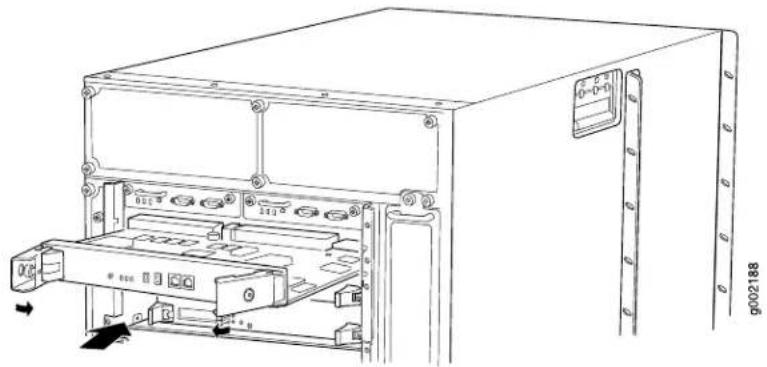
natural_image
Technical line drawing of a computer rack unit with mounting holes and internal compartments (no text or symbols)Related Documentation
T1600 Preventing Electrostatic Discharge Damage on page 552.
- Maintaining the T1600 Control Boards on page 477
•T1600 T Series Control Boards (T-CBs) Description on page 67
Replacing a T1600 LCC-CB
- Removing a T1600 LCC-CB on page 354
- Installing a T1600 LCC-CB on page 355
Removing a T1600 LCC-CB
The router can have up to two LCC-CBs. They are located in the upper rear of the chassis in the slots marked CBO and CB1. Each LCC-CB weighs approximately 5 lb (2.3 kg).

CAUTION: Before you replace an LCC-CB, you must take the host subsystem offline. If there is only one host subsystem, taking the host subsystem offline shuts down the router.
The backup LCC-CB is hot-removable and hot-insertable.

CAUTION: If the LCC-CB tobereplaced is associated with the Routing Engine currently functioning as the master Routing Engine, switch it to the backup before removing the LCC-CB.
To remove an LCC-CB (see Figure 171 on page 355):
- Take the host subsystem offline.
- Place an electrostatic bag or antistatic mat on a flat, stable surface.
- Attach an electrostatic discharge (ESD) grounding strap to your bare wrist, and connect the strap to one of the ESD points on the chassis.
- If the T1600 router is in a routing matrix, disconnect any cables that are plugged into the ports.
- Loosen the captive screws (using a Phillips (+) screwdriver, number 2) on the ejector handles on both sides of the LCC-CB faceplate.
- Flip the ejector handles outward to unseat the LCC-CB.
- Grasp the ejector handles and slide the LCC-CB about halfway out of the chassis.
- Place one hand underneath the LCC-CB to support it and slide it completely out of the chassis.
- Place the LCC-CB on the antistatic mat.
- If you are not replacing the LCC-CB now, install a blank panel over the empty slot.
Figure 171: Removing an LCC-CB

natural_image
Technical line drawing of an internal server rack with labeled ports and connectors (no readable text or symbols)Installing a T1600 LCC-CB
To install an LCC-CB (see Figure 172 on page 356):
- Attach an electrostatic discharge (ESD) grounding strap to your bare wrist, and connect the strap to one of the ESD points on the chassis.
- Verify that the CHASSIS ID and M/S switches on the LCC-CB faceplate are set correctly for your configuration. If you are installing the LCC-CB in a standalone router, the M/S switch must be set to S and the CHASSIS ID configuration switch must be set to 0.

NOTE: See Setting the Chassis ID and M/S Switch on the LCC-CB in the TX Matrix Plus Router Hardware Guide for instructions to set the switches when installing the LCC-CB in a T1600 that is part of a routing matrix.
- Carefully align the sides of the LCC-CB with the guides inside the chassis.
- Slide the LCC-CB into the chassis, carefully ensuring that it is correctly aligned.
- Grasp both ejector handles, and press them inward to seat the LCC-CB.
-
Tighten the captive screws on the ejector handles, using a Phillips (+) screwdriver, number 2.
-
If the T1600 router is in a routing matrix, reconnect any applicable cables that were previously plugged into the ports.
-
Verify that the LCC-CB is functioning normally:
- Check the LEDs on the LCC-CB faceplate. The green OK LED should light steadily a few minutes after the LCC-CB is installed. If power is applied to the Routing Engine and its corresponding LCC-CB is functioning normally, the LCC-CB comes online automatically.
If the FAIL LED is lit steadily, remove and install the LCC-CB again. If the FAIL LED still lights steadily, the LCC-CB is not functioning properly. Contact your customer support representative.
- Use the show chassis environment cb to check the status of the LCC-CB.
Figure 172: Installing an LCC-CB

natural_image
Technical line drawing of an internal server rack with labeled components and a black arrow pointing to a Control Panel (no text or symbols beyond labels)Related Documentation
T1600 Control Boards Description on page 66.
•Taking the T1600 Host Subsystem Offline on page 349
•T1600 Preventing Electrostatic Discharge Damage on page 552
Replacing a T1600 Routing Engine
-
Removing a T1600 Routing Engine on page 357
-
Installing the T1600 Routing Engine on page 359
-
Verifying the Installation of the T1600 Routing Engine on page 360
Removing a T1600 Routing Engine
The router can have one or two Routing Engines. They are located in the upper rear of the chassis in the slots marked RE0 and RE1. Each Routing Engine can weigh up to
2.4 lb (1.1 kg). The backup Routing Engine is hot-removable and hot-insertable.

CAUTION: Before you replace a Routing Engine, you must take the host subsystem offline. If there is only one host subsystem, taking the host subsystem offline shuts down the router. If the Routing Engine to be replaced is currently functioning as the master Routing Engine, switch it to be the backup before removing it. See "Taking the T1600 Host Subsystem Offline" on page 349.
To remove a Routing Engine (“Installing the T1600 Routing Engine” on page 359 and Figure 174 on page 358):
- Take the host subsystem offline as described in "Taking the T1600 Host Subsystem Offline" on page 349.
- Place an electrostatic bag or antistatic mat on a flat, stable surface.
- Attach an electrostatic discharge (ESD) grounding strap to your bare wrist, and connect the strap to one of the ESD points on the chassis.
- Loosen the captive screws on the corners of the Routing Engine cover.
- Grasp the Routing Engine cover by its edges and pull it free from the chassis (see Figure 173 on page 358).
- If applicable, loosen the screws on the extractor handles at either end of the Routing Engine faceplate, using a Phillips screwdriver.
- Press the red tabs on the ejector handles on both sides of the Routing Engine faceplate.
- Flip the ejector handles outward to unseat the Routing Engine.
- Grasp the Routing Engine by the ejector handles and slide it about halfway out of the chassis.
- Place one of your hands underneath the Routing Engine to support it and slide it completely out of the chassis.
- Place the Routing Engine on the antistatic mat.
- If you are not replacing the Routing Engine now, reinstall the Routing Engine cover and tighten the screws on the corners of the cover to secure it to the chassis (see "Installing the T1600 Routing Engine" on page 359).
Figure 173: Removing the Routing Engine Cover
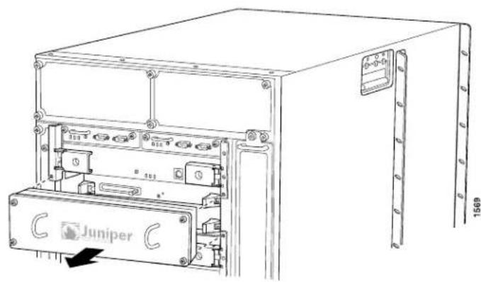
natural_image
Technical line drawing of a Juniper industrial control unit with mounting brackets and a central panel (no text or symbols)Figure 174: Removing a Routing Engine

natural_image
Technical line drawing of an electronic device chassis with mounting brackets and internal components (no text or symbols)Figure 175: Removing a C1800 Routing Engine
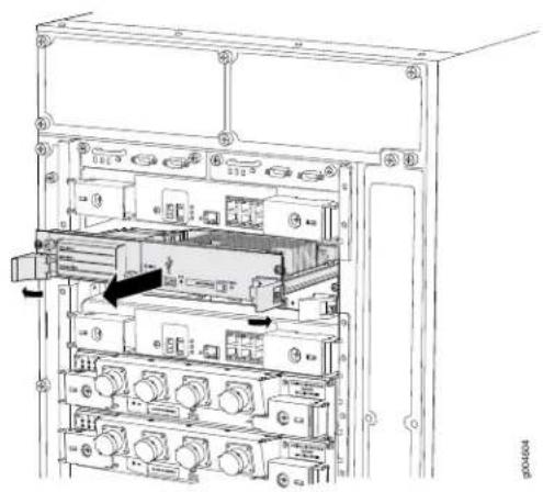
natural_image
Technical line drawing of an internal electronic device with multiple ports and a central rack (no text or symbols visible)Installing the T1600 Routing Engine
To install a Routing Engine (see Figure 176 on page 359):
- Attach an electrostatic discharge (ESD) grounding strap to your bare wrist, and connect the strap to one of the ESD points on the chassis.
- Ensure that the ejector handles are not in the locked position. If necessary, press the red tabs and flip the ejector handles outward.
- Place one hand underneath the Routing Engine to support it. With the other hand, grasp one of the ejector handles on the faceplate.
- Carefully align the sides of the Routing Engine with the guides inside the chassis.
- Slide the Routing Engine into the chassis until you feel resistance, then press the Routing Engine's faceplate until it engages the midplane connectors.
- Press both the ejector handles inward to seat the Routing Engine.
The Routing Engine might require several minutes to boot. - If applicable, tighten the screws on the extractor handles, using a Phillips screwdriver. Be sure to tighten the screws enough to seat the Routing Engine properly.
- Press the Routing Engine cover into place, then tighten the captive screws on the corners of the cover to secure it to the chassis (see Figure 177 on page 360).
Figure 176: Installing a Routing Engine

natural_image
Technical line drawing of a server rack unit with internal components and directional arrows indicating movement (no text or symbols)Figure 177: Reinstalling the Routing Engine Cover

natural_image
Technical line drawing of a Juniper industrial control unit with mounting hardware (no text or symbols)Verifying the Installation of the T1600 Routing Engine
If the router is powered on and the Routing Engine's corresponding control board is functioning normally, the Routing Engine comes online automatically. To verify that the Routing Engine is functioning normally:
-
Check the HOST0 and HOST1 LEDs on the craft interface.
-
The green OK LED should light steadily a few minutes after the Routing Engine is installed.
-
If the red FAIL LED is lit steadily, remove and install the Routing Engine again (see "Removing a T1600 Routing Engine" on page 357 and "Installing the T1600 Routing Engine" on page 359). Make sure that the Routing Engine is seated properly. If the FAIL LED still lights steadily, the Routing Engine is not functioning properly. Contact your customer support representative.
-
Verify that the Routing Engine is functioning properly. Display the status of the Routing Engine by issuing the show chassis routing-engine command:
user@host> show chassis routing-engine
Routing Engine status:
Slot 0:
Current state
Election priority
Temperature
CPU temperature
DRAM
Memory utilization
CPU utilization:
User
Background
Kernel
Interrupt
Idle
Model
Serial ID
Start time
Uptime
Master
Master (default)
32 degrees C / 89 degrees F
33 degrees C / 91 degrees F
2048 MB
8 percent
0 percent
0 percent
2 percent
0 percent
98 percent
RE-4.0
P13004101110
2007-04-30 08:38:22 PDT
2 days, 2 hours, 22 minutes, 43 seconds
Load averages:
1 minute
5 minute
15 minute
0.02
0.02
0.00
For more information about using the CLI, see the Junos OS manuals.
Related Documentation
Maintaining the T1600 Routing Engines on page 486.
•T1600 Routing Engine Description on page 42
•T1600 Routing Engine Interface Cable and Wire Specifications on page 167
Replacing a CompactFlash Card in a T1600 RE-C1800 Routing Engine
- Preparing to Replace a CompactFlash Card in a TI600 CI800 Routing Engine on page 361
- Removing a CompactFlash Card in a T1600 C1800 Routing Engine on page 363
- Installing a CompactFlash Card in a T1600 C1800 Routing Engine on page 364
- Copying Junos OS to the CompactFlash Card in a T1600 C1800 Routing Engine on page 365
Preparing to Replace a CompactFlash Card in a T1600 C1800 Routing Engine
To prepare to replace a CompactFlash card in a T1600 RE-C1800:
- Determine whether the host subsystem is functioning as the master or as the backup, using one of these methods:
- For standalone T1600 routers:
- Check the Host Subsystem LEDs on the craft interface. If the green MASTER LED is lit, the corresponding host subsystem is functioning as the master.
- Check the MASTER LED on the control board. If the blue MASTER LED is lit, the host subsystem is functioning as the master.
- Issue the following command:
user@host> show chassis routing-engine
Routing Engine status:
Slot 0:
Current state
Master
...
In this example, the Routing Engine in slot 0 is designated Master in the Current state field
- For T1600 routers in a routing matrix, verify that the master Routing Engine for all routers in the routing matrix are in the same slot.
To determine whether the host subsystems are functioning as the master or as the backup:
- Issue the show chassis routing-engine CLI command from the TX Matrix Plus router.
The master Routing Engine is designated Master in the Current state field. In this example, the Master Routing Engine is in Slot 0 for both sfc0-re0 and lcc0-re0.
user@host> show chassis routing-engine sfc0-re0:
Routing Engine status:
| Slot 0: | |
| Current state | Master |
| Election priority | Master (default) |
| Routing Engine status: | |
| Slot 1: | |
| Current state | Backup |
| Election priority | Backup (default) |
... 1cc0-re0:
Routing Engine status:
| Slot 0: | |
| Current state | Master |
| Election priority | Master (default) |
... Routing Engine status:
| Slot 1: | |
| Current state | Backup |
| Election priority | Backup (default) |
...
In this example, the Master Routing Engine is in Slot 0 for sfc0-re0 but Slot 1 for lcc0-re0.
user@host> show chassis routing-engine sfc0-re0:
Routing Engine status:
| Slot 0: | |
| Current state | Master |
| Election priority | Master (default) |
| Routing Engine status: | |
Slot 1:
| Current state | Backup |
| Election priority | Backup (default) |
... 1cc0-re0:
Routing Engine status:
| Slot 0: | |
| Current state | Backup |
| Election priority | Master (default) |
...
Routing Engine status:
| Slot 1: | |
| Current state | Master |
| Election priority | Backup (default) |
...
If the master host subsystem for any T1600 router lcc in a routing matrix is in a different slot from the master host subsystem for the TX Matrix Plus router sfc, use the request chassis routing-engine master switch lcc command to correct the problem.

NOTE: This command switches the master routing engine in the T1600 router.
user@host> request chassis routing-engine master switch lcc 0 warning: Traffic will be interrupted while the PFE is re-initialized Toggle mastership between routing engines ? [yes,no] (no) yes
Resolving mastership... Complete. The local routing engine becomes the master.
-
If the host subsystem is functioning as the master, switch it to backup.
-
For a standalone T1600 router, issue the request chassis routing-engine master switch command.
-
For a TI600 router in a routing matrix, issue the request chassis routing-engine master switch all-chassis command from the TX Matrix Plus router.
-
From the master Routing Engine, power down the backup Routing Engine.
-
For a standalone T1600 router, issue the request system power-off other-routing-engine command.
- For a T1600 router in a routing matrix, issue the request system power-off lcc number other-routing-engine command from the TX Matrix Plus router.
Replace number with a value from 0 through 3 for the line-card chassis (lcc).
Removing a CompactFlash Card in a T1600 C1800 Routing Engine
The CompactFlash card is located in the slot labeled CF on the Routing Engine faceplate. To remove the CompactFlash card:
- Place an electrostatic bag or antistatic mat on a flat, stable surface.
- Verify that the Online, DISK1, and CF LEDs on the backup Routing Engine faceplate are off.
- Attach an electrostatic discharge (ESD) grounding strap to your bare wrist, and connect the strap to one of the ESD points on the chassis.
- Using a Phillips (+) screwdriver, number 2, loosen the captive screws on the corners of the cover over the Routing Engine slots.
- Remove the cover from the Routing Engine slots.

CAUTION: Do not remove the cover if any of the LEDs are lit.
-
Press the eject button on the right side of the CompactFlash card slot to release the CompactFlash card.
-
The CompactFlash card pops partially out of the slot. Grasp the card and pull it completely out of the slot.
- Place the CompactFlash card on the antistatic mat.
Figure 178: Removing a CompactFlash Card
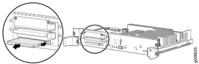
natural_image
Technical diagram of a computer rack with an inset showing a printer component (no text or symbols visible)Installing a CompactFlash Card in a T1600 C1800 Routing Engine
To install a CompactFlash card:
- Attach an electrostatic discharge (ESD) grounding strap to your bare wrist, and connect the strap to one of the ESD points on the chassis.
- Remove the cover from the Routing Engine slots by loosening the captive screws on the corners of the cover (using a Phillips (+) screwdriver, number 2).
- Insert the CompactFlash card into the CompactFlash card slot on the Routing Engine, with the logo facing up.

CAUTION: Be sure to insert the CompactFlash card with the label facing up. Inserting the CompactFlashcard incorrectly might damage the Routing Engine.
- Press the card firmly all the way into the slot.
- Reinstall the Routing Engine cover. Using a Phillips (+) screwdriver, number 2, tighten the screws on the corners of the cover to secure it to the Routing Engine.
-
From the master Routing Engine, power on the Routing Engine.
-
For a standalone T1600 router, issue the request system power-on other-routing-engine command.
- For a T1600 router in a routing matrix, issue the request system power-on lcc number other-routing-engine command from the TX Matrix Plus router.
Replace number with a value from 0 through 3 for the line-card chassis (lcc).

NOTE: After you replace a CompactFlash card, the Routing Engine boots from the solid-state disk (SSD). You may get an error message and be prompted for a keystroke. After you press the keystroke, it might take up to 10 minutes for the Routing Engine to reset and for the router to boot from the SSD.
Figure 179: Installing a CompactFlash Card
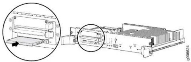
natural_image
Technical illustration of a computer chassis with an open lid and internal components, showing no visible text or symbols.Copying Junos OS to the CompactFlash Card in a T1600 C1800 Routing Engine
After installing the CompactFlash card for the first time, you must copy the software from the Routing Engine's solid-state disk (SSD) to the CompactFlash card.
To copy software to the CompactFlash card:
-
On the console or other management device connected to the Routing Engine, enter CLI operational mode and copy the currently running and active file system partitions on the router to standby partitions on the CompactFlash card.
-
On standalone T1600 routers, issue the request system snapshot partition command.
- On T1600 routers in a routing matrix, issue the request system snapshot partition lcc number command.
Replace number with a value from 0 through 3 for the line-card chassis (lcc).
- Wait until a message appears on the console confirming that the snapshot partition procedure is complete.
- Issue the request system reboot command to reboot the router's software.
- Issue the show system boot-messages command to verify that the CompactFlash card is listed as the primary boot device. The output lists the devices mounted. The CompactFlash card is located at ad0.
Related Documentation
T1600 Routing Engine Description on page 42.
•T1600 RE-C1800 Description on page 47
•T1600 RE-C1800 LEDs on page 49
•T1600 Craft Interface Host Subsystem LEDs on page 34
•T1600 Preventing Electrostatic Discharge Damage on page 552
Replacing a DIMM Module in a T1600 Routing Engine
- Removing a T1600 DIMM Module on page 366
- Installing a T1600 DIMM Module on page 366
Removing a T1600 DIMM Module
The DIMM modules are located on the top of the Routing Engine. To remove a DIMM module:
- Place an electrostatic bag or antistatic mat on a flat, stable surface.
- Attach an electrostatic discharge (ESD) grounding strap to your bare wrist, and connect the strap to one of the ESD points on the chassis.
- Remove the Routing Engine.
- Depending on which Routing Engine you are using, there are two different procedures for ejecting the DIMMs:
- For Routing Engines with an ejector on one side of the DIMM, press the plastic ejector of the DIMM module. The edge of the module raises upward.
- For Routing Engines with ejectors on each side of the DIMM, press the plastic ejectors on both sides of the DIMM module.
- Grasp the DIMM module, being careful not to touch any electrical components on the module, and firmly pull it out of the slot on the Routing Engine.
- Place the DIMM module on the antistatic mat or in the electrostatic bag.
- Push the plastic ejectors to close the empty DIMM module slot.
Installing a T1600 DIMM Module
To insert a DIMM module into the Routing Engine:
- Attach an electrostatic discharge (ESD) grounding strap to your bare wrist, and connect the strap to one of the ESD points on the chassis.
- Remove the DIMM module from its electrostatic bag.
- To open the empty DIMM slot, press the plastic ejectors open.
- Grasp the DIMM module by the edges, being careful not to touch any electrical components.
- Pressing firmly on both ends, push the module into the slot until the ejectors return completely to the closed position.
-
Install the Routing Engine.
-
You can view the SDRAM configuration and verify the DIMM was installed correctly by issuing the show chassis routing-engine command.
user@host> show chassis routing-engine
Routing Engine status:
Slot 0:
Current state
Election priority
Temperature
CPU temperature
DRAM
Master
Master (default)
32 degrees C / 89 degrees F
33 degrees C / 91 degrees F
2048 MB
| Memory utilization | 8 percent | ||
| CPU utilization: | |||
| User | 0 percent | ||
| Background | 0 percent | ||
| Kernel | 2 percent | ||
| Interrupt | 0 percent | ||
| Idle | 98 percent | ||
| Model | RE-4.0 | ||
| Serial ID | P13004101110 | ||
| Start time | 2007-04-30 08:38:22 PDT | ||
| Uptime | 2 days, 2 hours, 22 minutes, 43 seconds | ||
| Load averages: | 1 minute 5 minute 15 minute | ||
| 0.02 0.02 0.00 | |||
Figure 180: Installing the DIMM Module
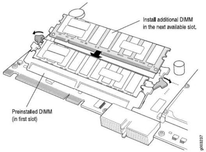
Related Documentation
T1600 Routing Engine Description on page 42. •Replacing a T1600 Routing Engine on page 356
Replacing a PC Card in a T1600 Routing Engine
- Removing a T1600 PC Card on page 367
- Installing the T1600 PC Card on page 368
Removing a T1600 PC Card
The PC Card is inserted into the slot labeled PC CARD on the Routing Engine. To remove the PC Card (see Figure 181 on page 368):
- Place an electrostatic bag or antistatic mat on a flat, stable surface.
-
Attach an electrostatic discharge (ESD) grounding strap to your bare wrist, and connect the strap to one of the ESD points on the chassis.
-
Remove the Routing Engine cover by loosening the captive screws on the corners of its faceplate.
-
On the Routing Engine faceplate, press the eject button on the right side of the PC Card slot once to release the button. Press again to release the PC Card.

NOTE: The Routing Engine in your router might have two PC Card slots. In this case, use either slot. Do not install more than one PC Card in the Routing Engine.
- The PC Card pops partially out of the slot. Grasp the card and pull it completely out of the slot.
- Place the PC Card on the antistatic mat.
- If you are not replacing the PC Card now, reinstall the Routing Engine cover and tighten the screws on the corners of the cover to secure it to the chassis.
Figure 181: Removing a PC Card

Installing the T1600 PC Card
To install a PC Card (see Figure 182 on page 369):
- Attach an electrostatic discharge (ESD) grounding strap to your bare wrist, and connect the strap to one of the ESD points on the chassis.
- If the Routing Engine cover is in place, remove the cover by loosening the captive screws on the corners of its faceplate.
- Insert the PC Card into the PC Card slot on the Routing Engine, with the Juniper Networks logo facing downward.

CAUTION: Be sure to insert the PC Card with the label facing downward. Inserting the PC Card incorrectly might damage the Routing Engine.

NOTE: The Routing Engine 1600 has two PC Card slots. In this case, use either slot. Do not install more than one PC Card in the Routing Engine.
- Press the card firmly all the way into the slot.
- Reinstall the Routing Engine cover and tighten the screws on the corners of the cover to secure it to the chassis.
Figure 182: Installing a PC Card

Related Documentation
T1600 Chassis Description on page 19.
•T1600 Physical Specifications on page 131
•T1600 Preventing Electrostatic Discharge Damage on page 552
Replacing a Solid-State Disk in a T1600 RE-C1800 Routing Engine

NOTE: For routers in a routing matrix, this procedure is supported for Junos OS Release 11.4R3 and later, or Junos OS Release 12.1R2 and later.
- Preparing to Replace a Solid-State Disk in a T1600 RE-C1800 Routing Engine on page 370
-
Removing a Solid-State Disk in a T1600 RE-C1800 Routing Engine on page 372
-
Installing a Solid-State Disk in a T1600 RE-C1800 Routing Engine on page 373
- Copying Junos OS to the Solid-State Disk in a T1600 RE-C1800 Routing Engine on page 374
Preparing to Replace a Solid-State Disk in a T1600 RE-C1800 Routing Engine
To prepare to replace a solid-state disk in a T1600 RE-C1800 Routing Engine:
- Determine whether the host subsystem is functioning as the master or as the backup, using one of these methods:
- For standalone T1600 routers:
- Check the host subsystem LEDs on the craft interface. If the green MASTER LED is lit, the corresponding host subsystem is functioning as the master.
- Check the MASTER LED on the control board. If the blue MASTER LED is lit, the host subsystem is functioning as the master.
- Issue the following command:
user@host> show chassis routing-engine
Routing Engine status:
Slot 0:
Current state
Master
...
In this example, the Routing Engine in Slot 0 is designated Master in the Current state field.
- For T1600 routers in a routing matrix, verify that the master Routing Engines for all routers in the routing matrix are in the same slot.
To determine whether the host subsystems are functioning as the master or as the backup:
- Issue the show chassis routing-engine CLI command from the TX Matrix Plus router.
The master Routing Engine is designated Master in the Current state field. In this example, the Master Routing Engine is in Slot 0 for both sfc0-re0 and lcc0-re0.
user@host> show chassis routing-engine
sfc0-re0:
Routing Engine status:
Slot 0:
Current state
Master
Election priority
Master (default)
Routing Engine status:
Slot 1:
Current state
Backup
Election priority
Backup (default)
...
1cc0-re0:
Routing Engine status:
Slot 0:
| Current state | Master |
| Election priority | Master (default) |
...
Routing Engine status:
Slot 1:
| Current state | Backup |
| Election priority | Backup (default) |
...
In this example, the Master Routing Engine is in Slot 0 for sfc0-re0 but Slot 1 for lcc0-re0.
user@host> show chassis routing-engine
sfc0-re0:
Routing Engine status:
Slot 0:
| Current state | Master |
| Election priority | Master (default) |
| Routing Engine status: | |
Slot 1:
| Current state | Backup |
| Election priority | Backup (default) |
...
1cc0-re0:
Routing Engine status:
Slot 0:
| Current state | Backup |
| Election priority | Master (default) |
...
Routing Engine status:
Slot 1:
| Current state | Master |
| Election priority | Backup (default) |
...
If the master host subsystem for any T1600 router lcc in a routing matrix is in a different slot from the master host subsystem for the TX Matrix Plus router sfc, use the request chassis routing-engine master switch lcc command to correct the problem.

NOTE: This commands switches themaster RoutingEngine in the TI600 router.
user@host> request chassis routing-engine master switch lcc 0 warning: Traffic will be interrupted while the PFE is re-initialized Toggle mastership between routing engines ? [yes,no] (no) yes
Resolving mastership... Complete. The local routing engine becomes the master.
- If the host subsystem is functioning as the master, switch it to backup.
- For a standalone T1600 router, issue the request chassis routing-engine master switch command.
- For a T1600 router in a routing matrix, issue the request chassis routing-engine master switch all-chassis command from the TX Matrix Plus router.
- From the master Routing Engine, power down the backup Routing Engine.
- For a standalone T1600 router, issue the request system power-off other-routing-engine command.
- For a T1600 router in a routing matrix, issue the request system power-off lcc number other-routing-engine command from the TX Matrix Plus router.
Replace number with a value from 0 through 3 for the line-card chassis (lcc).
Removing a Solid-State Disk in a T1600 RE-C1800 Routing Engine
The solid-state disk (SSD) is located in the slot labeled DISK1 on the Routing Engine faceplate.

NOTE: The DISK2 slot is not currently supported.
To remove an SSD from a Routing Engine:
-
Place an electrostatic bag or antistatic mat on a flat, stable surface.
-
Verify that the Online, DISK1, and CF LEDs on the backup Routing Engine faceplate are off.
-
Attach an electrostatic discharge (ESD) grounding strap to your bare wrist, and connect the strap to one of the ESD points on the chassis.
-
Using a Phillips (+) screwdriver, number 2, loosen the captive screws on the corners of the cover.
-
Remove the cover from the Routing Engine slots.

CAUTION: Do not remove the cover if any of the LEDs on the Routing Engine faceplate are lit.
-
Press the eject button on the right side of the DISK1 slot to release the SSD.
-
The SSD pops partially out of the slot. Grasp the SSD and carefully slide it completely out of the slot.
-
Place the SSD on the antistatic mat.
Figure 183: Removing an SSD

natural_image
Technical diagram of an electronic device showing internal components and a close-up view of the internal structure (no text or symbols present)Installing a Solid-State Disk in a T1600 RE-C1800 Routing Engine
To install an SSD in a Routing Engine:
- Insert the SSD into the DISK1 slot on the Routing Engine, with the logo facing down.

CAUTION: Be sure to insert the SSD with the label facing down. Inserting the SSD incorrectly might damage the Routing Engine.
- Slide the SSD into the slot until you feel resistance, carefully ensuring that it is correctly aligned.
- Reinstall the Routing Engine cover. Using a Phillips (+) screwdriver, number 2, tighten the screws on the corners of the cover to secure it to the Routing Engine.
-
From the master Routing Engine, power on the Routing Engine.
-
For a standalone T1600 router, issue the request system power-on other-routing-engine command.
- For a T1600 router in a routing matrix, issue the request system power-on lcc number other-routing-engine command from the TX Matrix Plus router.
Replace number with a value from 0 through 3 for the line-card chassis (lcc).
Figure 184: Installing an SSD
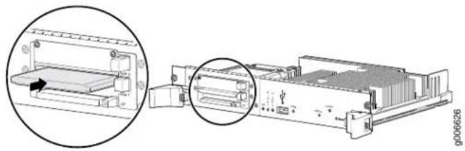
natural_image
Technical diagram of an electronic device showing internal components and a close-up view of the internal structure (no text or symbols present)Copying Junos OS to the Solid-State Disk in a T1600 RE-C1800 Routing Engine
After installing a solid-state disk (SSD) for the first time, you must copy the software from the Routing Engine's CompactFlash card to the SSD.
To copy software to the SSD:
- On the console or other management device connected to the Routing Engine, enter CLI operational mode.
- Partition the SSD. See request system partition hard-disk.
- For standalone T1600 routers, issue the request system partition hard-disk command.
- For T1600 routers in a routing matrix, issue the request system partition hard-disk lcc number command.
Replace number with a value from 0 through 3 for the line-card chassis (lcc).
- Wait until a message appears on the console confirming that the partition procedure is complete.
- Reboot the router's software.
- For standalone T1600 routers, issue the request system reboot command.
- For T1600 routers in a routing matrix, issue the request system reboot lcc number command.
Replace number with a value from 0 through 3 for the line-card chassis (lcc).
-
Back up the currently running and active file system partitions on the router to standby partitions that are not running.
-
For standalone T1600 routers, issue the request system snapshot command.
- For T1600 routers in a routing matrix, issue the request system snapshot lcc number command.
Replace number with a value from 0 through 3 for the line-card chassis (lcc).
- Wait until a message appears on the console confirming that the snapshot procedure is complete.
- Reboot the router's software again.
- For standalone T1600 routers, issue the request system reboot command.
- For T1600 routers in a routing matrix, issue the request system reboot lcc number command.
Replace number with a value from 0 through 3 for the line-card chassis (lcc).
-
Verify that the SSD is listed as the secondary boot device. The output lists the devices mounted. The SSD is located at ad1.
-
For standalone T1600 routers, issue the show system boot-messages command.
- For T1600 routers in a routing matrix, issue the show system boot-messages lcc number command.
Replace number with a value from 0 through 3 for the line-card chassis (lcc).
Related Documentation
•T1600 Routing Engine Description on page 42
•T1600 RE-C1800 Description on page 47
•T1600 RE-C1800 LEDs on page 49
•T1600 Craft Interface Host Subsystem LEDs on page 34
•T1600 Preventing Electrostatic Discharge Damage on page 552
CHAPTER 29
Replacing Line Card Components
- Replacing a T1600 FPC on page 377
- Replacing a T1600 PIC on page 384
- Replacing a T1600 PIC Cable on page 389
Replacing a T1600 FPC
The FPCs are hot-insertable and hot-removable. When you remove an FPC, the router continues to function, although the PIC interfaces installed on the FPC being removed no longer function.
- Removing a T1600 FPC on page 377
- Installing a T1600 FPC on page 380
Removing a T1600 FPC
The router holds up to eight FPCs, which are installed vertically in the front of the router. An empty FPC weighs approximately 25 lb (11.3 kg) and an FPC with PICs installed can weigh up to 37 lb (14.5 kg).
Each FPC slot not occupied by an FPC must be covered by an FPC blank panel. An FPC blank panel weighs 7 lb (3 kg).
To remove an FPC (see Figure 185 on page 379):
- Place an electrostatic bag or antistatic mat on a flat, stable surface.
- Attach an electrostatic discharge (ESD) grounding strap to your bare wrist, and connect the strap to one of the ESD points on the chassis.
- Use one of the following methods to take the FPC offline:
- Press and hold the FPC online/offline button. The green OK LED next to the button begins to blink. Hold the button down until the LED goes out. The LEDs and online/offline button for each FPC are located directly above it on the craft interface.
- Issue the following CLI command:
user@host>request chassis fpc slot slot-number offline
For more information about the command, see request chassis fpc.
- Disconnect the cables from the PICs installed in the FPC. If a PIC uses fiber-optic cable, immediately cover each transceiver and the end of each cable with a rubber safety cap. Arrange the disconnected cables in the cable management system, to prevent the cables from developing stress points.

WARNING: Do not look directly into a fiber-optic transceiver or into the ends of fiber-optic cables. Fiber-optic transceivers and fiber-optic cable connected to a transceiver emit laser light that can damage your eyes.

CAUTION: Do not leave a fiber-optic transceiver uncovered except when inserting or removing cable. The safety cap keeps the port clean and prevents accidental exposure to laser light.

CAUTION: Avoid bending fiber-optic cable beyond its minimum bend radius. An arc smaller than a few inches in diameter can damage the cable and cause problems that are difficult to diagnose.
- After you remove each PIC, immediately place it on an antistatic mat or in an electrostatic bag.
- If you are removing a Type 2 FPC or Type 3 FPC, loosen the screws inside the ejector handles at the top and bottom of the FPC faceplate.
- Simultaneously turn both the ejector handles counterclockwise to unseat the FPC.
- Grasp the handles and slide the FPC straight out of the card cage halfway.
- Place one hand around the front of the FPC (the PIC housing) and the other hand under it to support it. Slide the FPC completely out of the chassis, and place it on the antistatic mat or in the electrostatic bag.

CAUTION: The weight of the FPC is concentrated in the back end. Be prepared to accept the full weight—up to 37 lb (14.5 kg)—as you slide the FPC out of the chassis.
When the FPC is out of the chassis, do not hold it by the ejector handles, bus bars, or edge connectors. They cannot support its weight.
Do not stack FPCs on top of one another after removal. Place each one individually in an electrostatic bag or on its own antistatic mat on a flat, stable surface.
- If you are not reinstalling an FPC into the emptied FPC slot within a short time, install a blank FPC panel over the slot to maintain proper airflow in the FPC card cage.

CAUTION: After removing an FPC from the chassis, wait at least 30 seconds before reinserting it, removing an FPC from a different slot, or inserting an FPC into a different slot.
Figure 185: Removing an FPC

natural_image
Line drawing of an open industrial rack unit with internal compartments and control panel (no text or symbols)Installing a T1600 FPC

CAUTION: TheFPCpower connectoris located in the corner where the bottom and the connector edges meet. If a power connector prong becomes bent, it no longer aligns with the female connector on the midplane, and the FPC no longer functions.
To install an FPC (see Figure 187 on page 383 and Figure 188 on page 384):
- Attach an electrostatic discharge (ESD) grounding strap to your bare wrist, and connect the strap to one of the ESD points on the chassis.
- Place the FPC on an antistatic mat.
- Take each PIC to be installed in the replacement FPC out of its electrostatic bag and identify the slot on the FPC where it will be connected.
- Verify that each fiber-optic PIC has a rubber safety cap covering the PIC transceiver. If it does not, cover the transceiver with a safety cap.
- Install each PIC into the appropriate slot on the FPC. For information about installing a PIC, see "Installing a T1600 PIC" on page 387.
- Locate the slot in the FPC card cage in which you plan to install the FPC.
- Inspect the slot in the FPC card cage to verify that there are no missing or bent pins on the midplane.
- Inspect the FPC to verify that the connectors are not misaligned or damaged.
- Orient the FPC vertically with the component side facing to the right. Be sure the FPC is right-side up, with the components on the right of the FPC.

CAUTION: When the FPC is out of the chassis, do not hold it by the ejector handles, bus bars, or edge connectors. They cannot support its weight.
-
Carefully align the connector edge of the FPC with the appropriate empty slot in the chassis.
-
Lift the FPC into place and carefully align the bottom and top of the FPC with the guides inside the card cage.
Figure 186: Installing an FPC

natural_image
Illustration of a person installing or adjusting an open server rack cabinet with a magnified inset showing internal components (no text or symbols)Do not bend or damage prongs on power connector
- Gently rest the bottom edge of the FPC on the bottom edge of the slot opening, making contact a short distance forward of the power connector.

CAUTION: Take care not to bend or otherwise damage the power connector prongs.
-
Slowly slide the FPC into the slot until you feel resistance.
-
Align the ejector handles on the FPC faceplate in a position close to horizontal.
-
Simultaneously turn both ejector handles clockwise until you cannot turn them farther.
-
If you are installing a Type 2 FPC or Type 3 FPC, tighten the screws inside the ejector handles to secure the FPC. Do not overtighten them.
-
If any of the PICs on the FPC connect to fiber-optic cable, remove the rubber safety cap from each transceiver and cable.

WARNING: Do not look directly into a fiber-optic transceiver or into the ends of fiber-optic cables. Fiber-optic transceivers and fiber-optic cable connected to a transceiver emit laser light that can damage your eyes.
- Insert the appropriate cable into the cable connector ports on each PIC on the FPC. Secure the cables so that they are not supporting their own weight. Place excess cable out of the way in a neatly coiled loop, using the cable management system. Placing fasteners on a loop helps to maintain its shape.

CAUTION: Do not let fiber-optic cable hang free from the connector. Do not allow fastened loops of cable to dangle, which stresses the cable at the fastening point.

CAUTION: Avoid bending fiber-optic cable beyond its minimum bend radius. An arc smaller than a few inches in diameter can damage the cable and cause problems that are difficult to diagnose.
- Use one of the following methods to bring the FPC online:
- Press and hold the FPC online/offline button until the green OK LED next to the button lights steadily, in about 5 seconds. The LEDs and online/offline button for each FPC are located directly above it on the craft interface.
- Issue the following CLI command:
user@host>request chassis fpc slot slot-numberonline
For more information about the command, see request chassis pic.

CAUTION: After the OK LED lights steadily, wait at least 30 seconds before removing the FPC again, removing an FPC from a different slot, or inserting an FPC in a different slot.
You can also verify correct FPC and PIC functioning by issuing the show chassis fpc and show chassis fpc pic-status commands, as described in "Maintaining T1600 FPCs" on page 480 and "Maintaining T1600 PICs and PIC Cables" on page 488.
Figure 187: Installing an FPC

natural_image
Technical line drawing of a server rack unit with multiple drive bays and ventilation slots (no text or symbols)Figure 188: Connecting Fiber-Optic Cable to a PIC

Related Documentation
T1600 Preventing Electrostatic Discharge Damage on page 552.
•T1600 Flexible PIC Concentrator (FPC) Description on page 73
•Holding T1600 FPCs on page 481
•Storing T1600 FPCs on page 485
•Troubleshooting the T1600 FPCs on page 515
Replacing a T1600 PIC
- Removing a T1600 PIC on page 385
- Installing a T1600 PIC on page 387
Removing a T1600 PIC
PICs are hot-insertable and hot-removable. When you remove a PIC, the router continues to function, although the PIC interfaces being removed no longer function.
The PICs are located in the FPCs installed in the front of the router. A PIC weighs less than 2 lb (0.9 kg).
To remove a PIC (see Figure 189 on page 386):
- Place an electrostatic bag or antistatic mat on a flat, stable surface to receive the PIC. If the PIC connects to fiber-optic cable, have ready a rubber safety cap for each transceiver and cable.
- Attach an electrostatic discharge ESD grounding strap to your bare wrist, and connect the strap to one of the ESD points on the chassis.
- Use one of the following methods to take the PIC offline:
- Press and hold the online/offline button until the PIC LED goes out (about 5 seconds).
For a PIC installed in a Type 1 FPC, use a tool—such as a flat-blade screwdriver—to press the button slightly beneath the faceplate of the PIC. For a PIC installed in a Type 2 FPC or Type 3 FPC, use a narrow-ended tool that fits inside the opening that leads to the button.
- Issue the following CLI command:
user@host> request chassis pic fpc-slot fpc-slot pic-slot pic-slot offline
For more information about the command, see request chassis pic.
- Label the cables connected to the PIC so that you can later reconnect each cable to the correct PIC.
- Disconnect the cables from the PIC. If the PIC uses fiber-optic cable, immediately cover each transceiver and the end of each cable with a rubber safety cap.

WARNING: Do not look directly into a fiber-optic transceiver or into the ends of fiber-optic cables. Fiber-optic transceivers and fiber-optic cable connected to a transceiver emit laser light that can damage your eyes.

CAUTION: Do not leave a fiber-optic transceiver uncovered except when inserting or removing cable. The safety cap keeps the port clean and prevents accidental exposure to laser light.
- Arrange the cable in the cable management system to prevent it from dislodging or developing stress points. Secure the cable so that it is not supporting its own weight as it hangs to the floor. Place excess cable out of the way in a neatly coiled loop in the cable management system. Placing fasteners on the loop helps to maintain its shape.

CAUTION: Avoid bending fiber-optic cable beyond its minimum bend radius. An arc smaller than a few inches in diameter can damage the cable and cause problems that are difficult to diagnose.
- Unseat the PIC:
- Type 1 or Type 2 PIC—Loosen the captive screws at the top and bottom of the PIC faceplate.
- Type 3 PIC—Loosen the captive screw at the bottom of the PIC faceplate, then twist the ejector handle at the top of the faceplate and counterclockwise to unseat the PIC.
- Type 4 PIC—Twist the ejector handle at the bottom of the PIC faceplate, then twist the ejector handle at the top of the faceplate and counterclockwise to unseat the PIC.
- Slide the PIC out of the FPC card carrier, and place it in the electrostatic bag or on the antistatic mat.
- If you are not reinstalling a PIC into the emptied PIC slot within a short time, install a blank PIC panel over the slot to maintain proper airflow in the FPC card cage.
Figure 189: Removing a PIC

natural_image
Technical line drawing of an internal computer drive showing a cable connector and circuit board (no text or symbols)Installing a T1600 PIC
To install a PIC (see Figure 190 on page 388):
- Attach an electrostatic discharge (ESD) grounding strap to your bare wrist, and connect the strap to one of the ESD points on the chassis.
- If the PIC uses fiber-optic cable, verify that there is a rubber safety cap over each transceiver on the faceplate. Install a cap if necessary.
- Align the notches in the connector at the rear of the PIC with the notches in the PIC slot in the FPC and then slide the PIC in until it lodges firmly in the FPC.

CAUTION: Slide the PIC straight into the slot to avoid damaging the components on the bottom of the PIC.
-
Secure the PIC to the FPC faceplate:
-
Type 1 or Type 2 PICs—Tighten the captive screws at the top and bottom of the faceplate.
- Type 3 PICs—Turn the ejector handle at the top of the PIC faceplate clockwise, then tighten the captive screw at the bottom of the faceplate.
-
Type 4 PIC—Twist the ejector handle at the bottom of the PIC faceplate, then twist the ejector handle at the top of the faceplate and counterclockwise to unseat the PIC.
-
If the PIC uses fiber-optic cable, remove the rubber safety cap from each transceiver and the end of each cable.

WARNING: Do not look directly into a fiber-optic transceiver or into the ends of fiber-optic cables. Fiber-optic transceivers and fiber-optic cable connected to a transceiver emit laser light that can damage your eyes.

CAUTION: Do not leave a fiber-optic transceiver uncovered except when inserting or removing cable. The safety cap keeps the port clean and prevents accidental exposure to laser light.
- Insert the appropriate cables into the cable connectors on the PIC.
- Arrange each cable in the cable management system to prevent the cable from dislodging or developing stress points. Secure the cable so that it is not supporting its own weight as it hangs to the floor. Place excess cable out of the way in a neatly coil loop in the cable management system. Placing fasteners on the loop helps to maintain its shape.

CAUTION: Do not let fiber-optic cable hang free from the connector. Do not allow fastened loops of cable to dangle, which stresses the cable at the fastening point.

CAUTION: Avoid bending fiber-optic cable beyond its minimum bend radius. An arc smaller than a few inches in diameter can damage the cable and cause problems that are difficult to diagnose.
- Use one of the following methods to bring the PIC online:
- Press the PIC offline/online button until the PIC LED lights green. For a PIC installed in a Type 1 FPC, use a tool—such as a flat-blade screwdriver—to press the button slightly beneath the faceplate of the PIC. For a PIC installed in a Type 2 FPC or Type 3 FPC, use a narrow-ended tool that fits inside the opening that leads to the button.
- Issue the following CLI command:
user@host> request chassis pic fpc-slot fpc-slot pic-slot pic-slot online
For more information about the command, see request chassis pic.
The normal functioning status LED confirms that the PIC is online. You can also verify correct PIC functioning by issuing the show chassis fpc pic-status command.
Figure 190: Installing a PIC

natural_image
Technical line drawing of an electronic device chassis showing internal components and a 2044 model (no text or symbols present)Related Documentation
T1600 Preventing Electrostatic Discharge Damage on page 552.
- Maintaining T1600 PICs and PIC Cables on page 488
•T1600 PIC Description on page 86
•Troubleshooting the T1600 PICs on page 519
Replacing a T1600 PIC Cable
- Removing a T1600 PIC Cable on page 389
- Installing a T1600 PIC Cable on page 390
Removing a T1600 PIC Cable
Removing and installing PIC cables do not affect router function, except that a PIC does not receive or transmit data while its cable is disconnected. To remove a PIC cable:
- If the PIC connects to fiber-optic cable, have ready a rubber safety cap for each cable and transceiver.
- If removing all cables connected to the PIC, use one of the following methods to take the PIC offline:
- Press its online/offline button. For a Type 1 PIC, use a tool—such as a flat-blade screwdriver—to press the button slightly beneath the faceplate of the PIC. For a Type 2, Type 3, or Type 4 PIC, use a narrow-ended tool that fits inside the opening that leads to the button. Press and hold the button until the PIC LED goes out (about 5 seconds).
-
Issue the following CLI command:
user@host> request chassis pic fpc-slot fpc-slot pic-slot pic-slot offline
For more information about the command, see request chassis pic. -
Unplug the cable from the cable connector port. If the PIC uses fiber-optic cable, immediately cover each transceiver and the end of each cable with a rubber safety cap.

WARNING: Do not look directly into a fiber-optic transceiver or into the ends of fiber-optic cables. Fiber-optic transceivers and fiber-optic cable connected to a transceiver emit laser light that can damage your eyes.

CAUTION: Do not leave a fiber-optic transceiver uncovered except when inserting or removing cable. The safety cap keeps the port clean and prevents accidental exposure to laser light.
- Remove the cable from the cable management system and detach it from the destination port.
Installing a T1600 PIC Cable
To install a PIC cable (see Figure 191 on page 391):
-
Have ready a length of the type of cable used by the PIC. For cable specifications, see the T1600 Core Router Interface Module Reference.
-
If the PIC cable connector port is covered by a rubber safety plug, remove the plug.

WARNING: Do not look directly into a fiber-optic transceiver or into the ends of fiber-optic cables. Fiber-optic transceivers and fiber-optic cable connected to a transceiver emit laser light that can damage your eyes.

CAUTION: Do not leave a fiber-optic transceiver uncovered except when inserting or removing cable. The safety cap keeps the port clean and prevents accidental exposure to laser light.
-
Insert the cable connector into the cable connector port on the PIC faceplate.
-
Arrange the cable in the cable management system, to prevent it from dislodging or developing stress points. Secure the cable so that it is not supporting its own weight as it hangs to the floor. Place excess cable out of the way in a neatly coiled loop in the cable management system. Placing fasteners on the loop helps to maintain its shape.

CAUTION: Avoid bending fiber-optic cable beyond its minimum bend radius. An arc smaller than a few inches in diameter can damage the cable and cause problems that are difficult to diagnose.

CAUTION: Do not let fiber-optic cable hang free from the connector. Do not allow fastened loops of cable to dangle, which stresses the cable at the fastening point.
-
Insert the other end of the cable into the destination port.
-
Repeat the previous steps for any additional cables.
-
If the PIC is offline (its failure indicator LED is lit), use one of the following methods to bring the PIC online:
- Press the PIC offline/online button until the PIC LED lights green. For a Type 1 PIC, use a tool—such as a flat-blade screwdriver—to press the button slightly beneath the faceplate of the PIC. For a Type 2, Type 3, or Type 4 PIC, use a narrow-ended tool that fits inside the opening that leads to the button.
- Issue the following CLI command:
user@host>request chassis pic fpc-slot fpc-slot pic-slot pic-slot online
For more information about the command, see request chassis pic..
The normal functioning indicator LED confirms that the PIC is online. You can also verify correct PIC functioning by issuing the show chassis fpc pic-status command described in "Maintaining T1600 PICs and PIC Cables" on page 488.
Figure 191: Connecting Fiber-Optic Cable to a PIC

Related Documentation
•T1600 Preventing Electrostatic Discharge Damage on page 552
- Maintaining T1600 PICs and PIC Cables on page 488
•T1600 PIC Description on page 86
•Connecting PIC Cables to the T1600 Router on page 236
CHAPTER 30
Replacing Power System Components
- Tools and Parts Required for Replacing T1600 DC Power System Components on page 393
- Replacing a T1600 Three-Input 240-A DC Power Supply on page 394
- Replacing a T1600 Four-Input 240-A DC Power Supply on page 403
- Replacing a T1600 DC Power Supply Cable on a Three-Input 240-A DC Power Supply or Four-Input 240-A DC Power Supply on page 409
- Replacing a Front Air Filter on a T1600 AC or Three-Input 240-A or Four-Input 240-A DC Power Supply on page 415
- Replacing a T1600 Six-Input DC Power Supply on page 417
- Replacing a T1600 DC Power Supply Cable on a Six-Input DC Power Supply on page 421
- Replacing a T1600 Six-Input DC Power Supply Front Air Filter on page 423
- Replacing a T1600 Six-Input DC Power Supply Side Air Filter on page 424
- Replacing a T1600 Three-Phase Delta AC Power Supply on page 426
- Replacing a T1600 Three-Phase Delta AC Power Supply Cord on page 433
- Replacing a T1600 Three-Phase Wye AC Power Supply on page 438
- Replacing a T1600 Three-Phase Wye AC Power Supply Cord on page 444
Tools and Parts Required for Replacing T1600 DC Power System Components
To replace a DC power supply, you need the following tools and equipment:
• Phillips (+) screwdriver, number 2
- ESD wrist strap with cable
• 7/16-in. (11 mm) nut driver

CAUTION: You must use an appropriate torque-controlled tool to tighten the nuts. Applying excessive torque damages the terminal studs and the power supply. The absolute maximum torque that may be applied to this nut is 45 lb-in. (5.0 Nm).
- Wire cutters
- Flashlight
- Flat-blade (−) screwdriver
Related Documentation
Replacing a T1600 Three-Input 240-A DC Power Supply on page 394.
•Replacing a T1600 Four-Input 240-A DC Power Supply on page 403
•Replacing a T1600 Six-Input DC Power Supply on page 417
•T1600 DC Power Electrical Safety Guidelines on page 580
•General Safety Guidelines for Juniper Networks Devices on page 549
Replacing a T1600 Three-Input 240-A DC Power Supply
The T1600 router has either one nonredundant power supply or two redundant, load-sharing power supplies. Each redundant power supply is hot-insertable and hot-removable. When a redundant power supply is powered down or removed, the other power supply automatically assumes the entire electrical load for the router. If you have only one power supply, you must power off the system before removing the power supply.
- Removing a T1600 Three-Input 240-A DC Power Supply on page 394
- Setting the Input Mode Switch on a T1600 Three-Input 240-A DC Power Supply on page 397
- Installing a T1600 Three-Input 240-A DC Power Supply on page 398
- Replacing a Cable Restraint on the T1600 Three-Input 240-A DC Power Supply on page 399
- Connecting a Replacement T1600 Three-Input 240-A DC Power Supply on page 401
- Powering On a Replacement T1600 Three-Input 240-A DC Power Supply on page 403
Removing a T1600 Three-Input 240-A DC Power Supply
To remove a three-input 240-A DC power supply:
- Switch off the external circuit breakers to the power supply being removed. Make sure that the voltage across the DC power source cable leads is 0 V and that there is no chance that the cables might become active during the removal process.
- Attach an electrostatic discharge (ESD) grounding strap to your bare wrist, and connect the strap to one of the ESD points on the chassis.
- Switch the circuit breakers on the power supply faceplate to the off position (O).

NOTE: After powering off a power supply, wait at least 60 seconds before turning it back on.
-
Remove the clear plastic cover protecting the terminal studs on the faceplate.
-
Using a 7/16-in. (11 mm) nut driver or wrench, remove the nuts and washers from the terminal studs (see Figure 192 on page 395).

CAUTION: You must ensure that power connections maintain the proper polarity. The power source cables might be labeled (+) and (−) to indicate their polarity. There is no standard color coding for DC power cables. The color coding used by the external DC power source at your site determines the color coding for the leads on the power cables that attach to the terminal studs on each power supply.
Figure 192: Disconnecting Power Cables from the DC Power Supply

- Remove the cable lugs from the terminal studs.
- Loosen the captive screw or screws on the cable restraint on the right edge of the power supply faceplate.
- Carefully move the power cables out of the way.
- Loosen the captive screws on the lower corners of the power supply faceplate completely.
- Twist the ejector handles on the upper corners of the faceplate counterclockwise to unseat the power supply.
- Grasp the handle on the power supply faceplate and pull firmly. Slide it halfway out of the chassis (see Figure 194 on page 397).

CAUTION: Each three-input 240-ADC power supply weighs approximately 25 lb (11.3 kg). Be prepared to support the full weight of the power supply as you remove it from the router.
- Place one hand underneath the power supply to support it, and slide it completely out of the chassis.

WARNING: Do not touch the power connectors on the rear of the power supply (see Figure 193 on page396). They can contain dangerous voltages.
Figure 193: Rear of the Power Supply Showing Midplane Connectors

natural_image
Technical line drawing of a rectangular electronic device casing with mounting holes and internal components (no text or symbols)
CAUTION: Do not leave a power supply slot empty for more than a short time while the router is operational. For proper airflow, the power supply must remain in the chassis or a blank panel must be used in an empty slot.
Figure 194: Removing a Three-Input 240-A DC Power Supply

Setting the Input Mode Switch on a T1600 Three-Input 240-A DC Power Supply

NOTE: Do not set the input mode switch if the power supply is installed in the chassis. If the powersupply is already installed, you must remove it before setting the input mode switch.

NOTE: For the T1600 router, you must set the input-mode switch to 3-INPUT mode.
To set the input mode switch:
- Using a screwdriver, loosen the captive screw holding the metal cover over the input mode switch (see Figure 195 on page 398).
- Rotate the metal cover away from the input mode switch to expose the switch.
- Check the setting of the input mode switch. Use a flashlight, if necessary. In 3-INPUT mode, the switch is located all the way to the left.
- Use a sharp, nonconductive object to slide the switch all the way to the left to set the power supply to 3-INPUT.

CAUTION: Do not use a pencil, because fragments can breakoff and cause damage to the power supply.
- Rotate the metal cover over the input mode switch, and use a screwdriver to tighten the captive screw.
Figure 195 on page 398 shows the input mode switch.
Figure 195: Three-Input 240-ADC Power Supply

Installing a T1600 Three-Input 240-A DC Power Supply
Each three-input 240-A DC power supply weighs approximately 25 lb (11.3 kg). To install a three-input 240-A DC power supply:
- Make sure that the voltage across the DC power source cable leads is 0 V and that there is no chance that the cables might become active during installation.
- Attach an electrostatic discharge (ESD) grounding strap to your bare wrist, and connect the strap to one of the ESD points on the chassis.
- Switch the circuit breakers on the power supply faceplate to the OFF position (O).
- Using both hands, slide the power supply into the chassis until you feel resistance (see Figure 196 on page 399).
- Twist the ejector handles at the upper corners of the power supply faceplate clockwise until they stop.
- Tighten the captive screws at the lower corners of the power supply faceplate to secure the power supply in the chassis.
Figure 196: Installing a Three-Input 240-ADC Power Supply

Replacing a Cable Restraint on the T1600 Three-Input 240-A DC Power Supply
- Removing the Standard Cable Restraint from the T1600 Three-Input 240-A Power Supply on page 399
- Installing the Optional Cable Restraint on the T1600 Three-Input 240-A DC Power Supply on page 400
Removing the Standard Cable Restraint from the T1600 Three-Input 240-A Power Supply
Each three-input 240-A power supply is shipped with the standard cable restraint, as shown in Figure 197 on page 400. Two optional cable restraints are shipped in the accessory box for the T1600 router and in the T1600 upgrade kit.
If your DC power cables are too large or inflexible to fit into the standard cable restraint, we recommend that you remove the standard cable restraint and install the optional cable restraint (see Figure 198 on page 400) on each three-input 240-A power supply.

NOTE: Before you remove a chassis from a rack or cabinet, you must remove the optional cable restraint from the three-input 240-A power supply.
The cable restraint is located on the right edge of the power supply faceplate. To remove the standard cable restraint:
- Loosen the captive screw on the standard cable restraint or captive screws on the optional cable restraint.
- Remove the cable restraint from the power supply.
Figure 197: Three-Input 240-A Power Supply with the Standard Cable Restraint

Figure 198: Three-Input 240-A Power Supply with the Optional Cable Restraint

Installing the Optional Cable Restraint on the T1600 Three-Input 240-A DC Power Supply
To install the optional cable restraint:
- Align the two captive screws on the optional cable restraint with the two threaded holes located at the right edge of the power supply faceplate.
- Fasten the captive screws.
Connecting a Replacement T1600 Three-Input 240-A DC Power Supply
To connect a three-input 240-A DC power supply to the power sources:
- Attach an electrostatic discharge (ESD) grounding strap to your bare wrist, and connect the strap to one of the ESD points on the chassis.
- Verify that a licensed electrician has attached cable lugs to the power cables that you supply.
- Verify that the voltage across the DC power source cables leads is 0 V and that there is no chance that the cables might become active during installation. If needed, switch off the customer site circuit breakers.
- Verify that the circuit breakers on the power supply faceplate are in the OFF position (O).
- Remove the clear plastic cover protecting the terminal studs on the faceplate.
- Remove the nut and washer from each power terminal stud.

CAUTION: You must ensure that power connections maintain the proper polarity. The power source cables might be labeled (+) and (−) to indicate their polarity. There is no standard color coding for DC power cables. The color coding used by the external DC power source at your site determines the color coding for the leads on the power cables that attach to the terminal studs on each power supply.
- Attach the lugs on the DC source power cables to the terminal studs.
a. Attach the positive (+) DC source power cable lugs to the RETURN (return) terminals.
b. Attach the negative (−) DC source power cable lugs to the -48V (input) terminals.
Secure the cable lugs to the terminal studs, first with a washer, then with a nut (see Figure 199 on page 402). Use a 7/16-in. (11-mm) nut driver to tighten the nut. Apply between 23 lb-in. (2.6 Nm) and 25 lb-in. (2.8 Nm) of torque to each nut.

CAUTION: You must use an appropriate torque-controlled tool to tighten the nuts. Applying excessive torque damages the terminal studs and the power supply. The absolute maximum torque that may be applied to this nut is 45 lb-in. (5.0 Nm).

NOTE: For power supplies set to 3-INPUT mode (required for the T1600 router), connect two DC power cables, one for RETURN and one for -48 V, to each of the three inputs.
- Loosen the captive screw or screws on the cable restraint on the right edge of the power supply faceplate.
- Route the DC power cables through the cable restraint.
- Tighten the cable restraint captive screw or screws to hold the power cables in place.
- Verify that the ground and power cabling are correct, that they are not touching or blocking access to other hardware components, and that they do not drape where people could trip on them.
- Replace the clear plastic cover over the terminal studs on the faceplate.
Figure 199: Connecting DC Power Cables to the Three-Input 240-A DC Power Supply (PWR-T1600-3-80-DC-S)
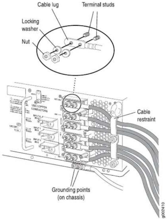
Powering On a Replacement T1600 Three-Input 240-A DC Power Supply
To power on a replacement three-input 240-A power supply:
-
Attach an electrostatic discharge (ESD) grounding strap to your bare wrist, and connect the strap to one of the ESD points on the chassis.
-
Switch on the customer site circuit breakers to provide voltage to the DC power source cables.

NOTE: If the system is completely powered off when you power on the power supply, the Routing Engine boots as the power supply completes its startup sequence. If the Routing Engine finishes booting, you must power off the system before you power on again. After powering off a power supply, wait at least 60 seconds before turning it back on.
-
Verify that the INPUT PRESENT LEDs on the power supply faceplate are lit steadily, indicating that the inputs are receiving power.
-
Switch the circuit breakers on the power supply to the ON position (I).

NOTE: After a power supply is powered on, it can take up to 60 seconds forstatus indicators—such as the LEDsonthepower supply, the command output displays, and messages on the LCD display on the craft interface—to indicate that the powersupply is functioning normally. Ignore error indicators that appear during the first 60 seconds.
-
Verify that the CB ON LEDs on the power supply faceplate are lit steadily, indicating that the circuit breakers are on.
-
Verify that the DC OK LED on the power supply faceplate is lit steadily, indicating that the power supply is correctly installed and is functioning properly. The DC OK LED blinks momentarily, then lights steadily.
Related Documentation
T1600 Preventing Electrostatic Discharge Damage on page 552.
•Connecting a Replacement T1600 Three-Input 240-A DC Power Supply on page 401
- Maintaining the T1600 Power Supplies on page 490
•Powering On a Replacement T1600 Three-Input 240-A DC Power Supply on page 403
•T1600 Three-Input 240-A DC Power Supply Specifications on page 138
Replacing a T1600 Four-Input 240-A DC Power Supply
The T1600 router has either one nonredundant power supply or two redundant, load-sharing power supplies. Each redundant power supply is hot-insertable and hot-removable. When a redundant power supply is powered down or removed, the other
power supply automatically assumes the entire electrical load for the router. If you have only one power supply, you must power off the system before removing the power supply.
- Removing a T1600 Four-Input 240-A DC Power Supply on page 404
- Installing a T1600 Four-Input 240-A Power Supply on page 406
Removing a T1600 Four-Input 240-A DC Power Supply
To remove a four-input 240-A DC power supply:
- Switch off the customer site circuit breakers to the power supply being removed. Make sure that the voltage across the DC power source cable leads is 0 V and that there is no chance that the cables might become active during the removal process.
- Attach an electrostatic discharge (ESD) grounding strap to your bare wrist, and connect the strap to one of the ESD points on the chassis.
- Switch the circuit breakers on the power supply faceplate to the off position (O).
Figure 200: Four-Input 240-A DC Power Supply
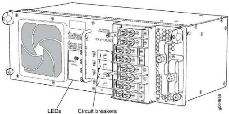

NOTE: After powering off a power supply, wait at least 60 seconds before turning it back on.
- Remove the clear plastic cover protecting the terminal studs on the faceplate.
- Using a 7/16-in. (11 mm) nut driver, remove the nuts and washers from the terminal studs (see Figure 201 on page 405).

CAUTION: You must ensure that power connections maintain the proper polarity. The power source cables might be labeled (+) and (−) to indicate their polarity. There is no standard color coding for DC power cables. The color coding used by the external DC power source at your site determines the color coding for the leads on the power cables that attach to the terminal studs on each power supply.
Figure 201: Disconnecting Power Cables from the Four-Input 240-A DC Power Supply
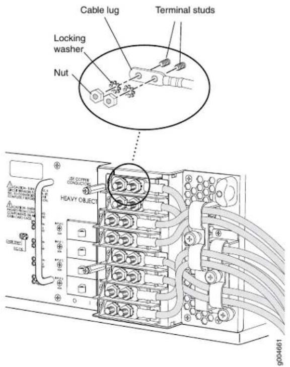
- Remove the cable lugs from the terminal studs.
- Loosen the captive screw or screws on the cable restraint on the right edge of the power supply faceplate.
- Carefully move the power cables out of the way.
- Loosen the captive screws on the lower corners of the power supply faceplate completely.
- Twist the ejector handles on the upper corners of the faceplate counterclockwise to unseat the power supply.
- Grasp the handle on the power supply faceplate and pull firmly. Slide it halfway out of the chassis (see Figure 202 on page 406).

CAUTION: Each four-input 240-ADC power supply weighs approximately 26.6 lb (12.0 kg). Be prepared to support the full weight of the power supply as you remove it from the router.
- Place one hand underneath the power supply to support it and slide it completely out of the chassis.
Figure 202: Removing a Four-Input 240-A DC Power Supply

natural_image
Technical line drawing of a server rack with multiple drive bays and cable routing (no text or labels)
WARNING: Do not touch the power connectors on the rear of the power supply (see Figure 203 on page406). They can contain dangerous voltages.
Figure 203: Rear of the Power Supply Showing Midplane Connectors

natural_image
Line drawing of a rectangular electronic device with two internal slots and mounting holes (no text or symbols)Installing a T1600 Four-Input 240-A Power Supply
Each four-input 240-A DC power supply weighs approximately 26.6 lb (12.0 kg). To install a four-input 240-A DC power supply:
- Make sure that the voltage across the DC power source cable leads is 0 V and that there is no chance that the cables might become active during installation.
- Attach an electrostatic discharge (ESD) grounding strap to your bare wrist, and connect the strap to one of the ESD points on the chassis.
-
Switch the circuit breakers on the power supply faceplate to the OFF position (O).
-
Using both hands, slide the power supply into the chassis until you feel resistance (see Figure 205 on page 409).
- Twist the ejector handles at the upper corners of the power supply faceplate clockwise until they stop.
- Tighten the captive screws at the lower corners of the power supply faceplate to secure the power supply in the chassis.
- Verify that a licensed electrician has attached cable lugs to the power cables that you supply.
- Remove the clear plastic cover protecting the terminal studs on the faceplate.
- Remove the nut and washer from each power terminal stud.

CAUTION: You must ensure that power connections maintain the proper polarity. The power source cables might be labeled (+) and (−) to indicate their polarity. There is no standard color coding for DC power cables. The color coding used by the external DC power source at your site determines the color coding for the leads on the power cables that attach to the terminal studs on each power supply.
- Attach the lugs on the DC source power cables to the terminal studs.
a. Attach the positive (+) DC source power cable lugs to the RETURN (return) terminals.
b. Attach the negative (−) DC source power cable lugs to the -48V (input) terminals.
Secure the cable lugs to the terminal studs, first with a washer, then with a nut (see Figure 204 on page 408). Use a 7/16-in. (11 mm) nut driver to tighten the nut. Apply between 23 lb-in. (2.6 Nm) and 25 lb-in. (2.8 Nm) of torque to each nut.

CAUTION: You must use an appropriate torque-controlled tool to tighten the nuts. Applying excessive torque damages the terminal studs and the power supply. The absolute maximum torque that may be applied to this nut is 45 lb-in. (5.0 Nm).
Figure 204: Connecting a Power Cable to a Four-Input 240-A DC Power Supply

- Loosen the captive screws on the cable restraint on the right edge of the power supply faceplate.
- Route the DC power cables through the cable restraint.
- Tighten the cable restraint captive screws to hold the power cables in place.
- Verify that the power cabling is correct, that the power cables do not touch or block access to other hardware components, and that they do not drape where people could trip on them.
- Replace the clear plastic cover over the terminal studs on the faceplate.
- Switch on the customer site circuit breakers to provide voltage to the DC power source cables.
- Verify that the INPUT PRESENT LEDs on the power supply faceplate are lit steadily, indicating that the inputs are receiving power.
- Switch the circuit breakers on the power supply to the ON position (I).

NOTE: After a power supply is powered on, it can take up to 60 seconds forstatus indicators—such as the LEDs on the power supply, the command output displays, and messages on the LED display on the craft interface—to indicate that the power supply is functioning normally. Ignore error indicators that appear during the first 60 seconds.
- Verify that the CB ON LEDs on the power supply faceplate are lit steadily, indicating that the circuit breakers are on.
- Verify that the DC OK LED on the power supply faceplate is lit steadily, indicating that the power supply is correctly installed and is functioning properly. The DC OK LED blinks momentarily, then lights steadily.
Figure 205: Installing a Four-Input 240-A DC Power Supply

natural_image
Technical diagram of a server rack with connected modules and fans, showing internal wiring (no text or labels)Related Documentation
T1600 Power System Description on page 105.
•Maintaining the T1600 Power Supplies on page 490
•Troubleshooting the T1600 Power System on page 516
•T1600 Preventing Electrostatic Discharge Damage on page 552
•T1600 General Electrical Safety Guidelines on page 575
Replacing a T1600 DC Power Supply Cable on a Three-Input 240-A DC Power Supply or Four-Input 240-A DC Power Supply
- Removing a T1600 DC Power Supply Cable From a Three-Input 240-A DC Power Supply or Four-Input 240-A DC Power Supply on page 410
- Installing a T1600 DC Power Supply Cable on a Three-Input 240-A DC Power Supply or Four-Input 240-A DC Power Supply on page 412
Removing a T1600 DC Power Supply Cable From a Three-Input 240-A DC Power Supply or Four-Input 240-A DC Power Supply
You can use this procedure to remove a DC power cable from a three-input 240-A DC power supply or a four-input 240-A DC power supply. To remove a DC power supply cable:
- Attach an electrostatic discharge (ESD) grounding strap to your bare wrist, and connect the strap to an approved site ESD grounding point. See the instructions for your site.
- Switch off the customer site circuit breakers for all the cables attached to the power supply. Make sure that the voltage across the DC power source cable leads is 0 V and that there is no chance that the cables might become active during the removal process.
- Remove the power cable from the external DC power source.
- Attach an electrostatic discharge (ESD) grounding strap to your bare wrist, and connect the strap to one of the ESD points on the chassis.
- Switch the circuit breakers on the power supply faceplate to the off position (O).
- Remove the clear plastic cover protecting the terminal studs on the faceplate.
- Remove the nut and washer from the terminal stud on the power supply (see Figure 206 on page 411). (Use a 7/16-in. (11 mm) nut driver.)

CAUTION: You must ensure that power connections maintain the proper polarity. The power source cables might be labeled (+) and (−) to indicate their polarity. There is no standard color coding for DC power cables. The color coding used by the external DC power source at your site determines the color coding for the leads on the power cables that attach to the terminal studs on each power supply.
Figure 206: Disconnecting a Power Cable from a Three-Input 240-A DC Power Supply

Figure 207: Disconnecting a Power Cable from a Four-Input 240-A DC Power Supply

- Remove the cable lug from the terminal stud on the power supply.
- Loosen the captive screw or screws on the cable restraint on the right edge of the power supply faceplate.
- Carefully move the power cable out of the way.
Installing a T1600 DC Power Supply Cable on a Three-Input 240-A DC Power Supply or Four-Input 240-A DC Power Supply
You can use this procedure to install a DC power cable on either a three-input 240-A DC power supply or a four-input 240-A DC power supply. To install a DC power supply cable:
- Locate a DC power cable that meets the specifications defined in "T1600 DC Power Cables and Lugs" on page 144.

CAUTION: A licensed electrician must attach a cable lug to the power cable that yousupply. A cablewith an incorrectly attached lug can damage the router.
- Route the power cable through the cable restraint.
- Attach the lug on the DC source power cable to the terminal stud.
a. Attach a positive (+) DC source power cable lug to the RETURN (return) terminals.
b. Attach a negative (−) DC source power cable lug to the -48V (input) terminals.
Secure the cable lug to the terminal stud, first with a washer, then with a nut (see Figure 208 on page 413 and Figure 209 on page 414). Use a 7/16-in. (11-mm) nut driver to tighten the nut. Apply between 23 lb-in. (2.6 Nm) and 25 lb-in. (2.8 Nm) of torque to each nut.

CAUTION: You must use an appropriate torque-controlled tool to tighten the nuts. Applying excessive torque damages the terminal studs and the power supply. The absolute maximum torque that may be applied to this nut is 45 lb-in. (5.0 Nm).
Figure 208: Connecting a Power Cable to a Three-Input 240-A DC Power Supply

Figure 209: Connecting a Power Cable to a Four-Input 240-A DC Power Supply

- Tighten the cable restraint captive screw or screws to hold the power cable in place.
- Replace the clear plastic cover over the terminal studs on the faceplate.
- Verify that the DC source power cabling is correct, that the power cable is not touching or blocking access to router components, and it does not drape where people could trip on it.
- Attach the other end of the power cable to the external DC power source.
- Switch on the customer site circuit breakers.
- Verify that the INPUT PRESENT LEDs on the power supply faceplate are lit steadily, indicating that the inputs are receiving voltage.
- Switch the circuit breakers on the power supply to the ON position (I).

NOTE: After a power supply is powered on, it can take up to 60 seconds forstatus indicators—such as the LEDs on the power supply,the command output displays, and messages on the LED display on the craft interface—to indicate that the power supply is functioning normally. Ignore error indicators that appear during the first 60 seconds.
- Verify that the CB ON LEDs on the power supply faceplate are lit steadily, indicating that the circuit breakers are on..
- Verify that the DC OK LED on the power supply faceplate is lit steadily, indicating that the power supply is correctly installed and is functioning properly. The DC OK LED blinks momentarily, then lights steadily.
Related Documentation
T1600 Power System Description on page 105.
- Maintaining the T1600 Power Supplies on page 490
•Troubleshooting the T1600 Power System on page 516
•T1600 Preventing Electrostatic Discharge Damage on page 552
•T1600 General Electrical Safety Guidelines on page 575
Replacing a Front Air Filter on a T1600 AC or Three-Input 240-A or Four-Input 240-A DC Power Supply
You can use this procedure for a three-input 240-A DC power supply, four-input 240-A DC power supply, three-phase delta AC power supply, or three-phase wye AC power supply.
- Removing a Front Air Filter on a T1600 AC or Three-Input 240-A or Four-Input 240-A DC Power Supply on page 415
- Installing a Front Air Filter on a T1600 AC or Three-Input 240-A or Four-Input 240-A DC Power Supply on page 416
Removing a Front Air Filter on a T1600 AC or Three-Input 240-A or Four-Input 240-A DC Pow Supply
To remove a power supply front air filter element (see Figure 210 on page 416):
- Attach an electrostatic discharge (ESD) grounding strap to your bare wrist, and connect the strap to one of the ESD points on the chassis.
- Grasp the filter cover on the power supply faceplate and pull it straight off the power supply.
- Remove the front air filter element.
Figure 210: Removing a Front Air Filter Element

Installing a Front Air Filter on a T1600 AC or Three-Input 240-A or Four-Input 240-A DC Pow Supply
To install a power supply front filter element (see Figure 211 on page 416):
- Attach an electrostatic discharge (ESD) grounding strap to your bare wrist, and connect the strap to one of the ESD points on the chassis.
- Install a new filter element.
- Press the filter cover straight onto the power supply faceplate until all four sides click into place.
Figure 211: Installing a Front Air Filter Element

Related Documentation
Maintaining the T1600 Power Supplies on page 490.
Replacing a T1600 Six-Input DC Power Supply
- Removing a T1600 Six-Input DC Power Supply on page 417
- Installing a T1600 Six-Input DC Power Supply on page 419
Removing a T1600 Six-Input DC Power Supply
To remove a six-input DC power supply:
- Switch off the customer site circuit breakers to the power supply being removed. Make sure that the voltage across the DC power source cable leads is 0 V and that there is no chance that the cables might become active during the removal process.

NOTE: After powering off a power supply, wait at least 60 seconds before turning it back on.
- Remove the clear plastic cover protecting the terminal studs on the faceplate.
Figure 212: DC Power Supply

- Using a 7/16-in. (11 mm) nut driver, remove the nuts and washers from the terminal studs (see Figure 213 on page 418).

CAUTION: You must ensure that power connections maintain the proper polarity. The power source cables might be labeled (+) and (−) to indicate their polarity. There is no standard color coding for DC power cables. The color coding used by the external DC power source at your site determines the color coding for the leads on the power cables that attach to the terminal studs on each power supply.
Figure 213: Disconnecting Power Cables from the DC Power Supply

- Remove the cable lugs from the terminal studs.
- Loosen the captive screws on the cable restraints on the right edge of the power supply faceplate.
- Carefully move the power cables out of the way.
- Loosen the captive screws on the lower corners of the power supply faceplate completely.
- Twist the ejector handles on the upper corners of the faceplate counterclockwise to unseat the power supply.
- Grasp the handle on the power supply faceplate, and pull firmly. Slide it halfway out of the chassis (see Figure 214 on page 418).

CAUTION: Each DC power supply weighs approximately 39.7 lb (18.0 kg). Be prepared to support the full weight of the power supply as you remove it from the router.
- Place one hand underneath the power supply to support it, and slide it completely out of the chassis.
Figure 214: Removing a DC Power Supply

natural_image
Diagram of server rack with red cable routing from multiple ports (no text or labels)
WARNING: Do not touch the power connectors on the rear of the power supply (see Figure 215 on page 419). They can contain dangerous voltages.
Figure 215: Rear of the Power Supply Showing Midplane Connectors

natural_image
Technical line drawing of a rectangular electronic device with internal components and mounting holes (no text or symbols)Installing a T1600 Six-Input DC Power Supply
Each DC power supply weighs approximately 39.7 lb (18.0 kg). To install a six-input DC power supply:
- Make sure that the voltage across the DC power source cable leads is 0 V and that there is no chance that the cables might become active during installation.
- Attach an electrostatic discharge (ESD) grounding strap to your bare wrist, and connect the strap to one of the ESD points on the chassis.
- Using both hands, slide the power supply into the chassis until you feel resistance (see Figure 216 on page 419).
Figure 216: Inserting the DC Power Supply into the Chassis

natural_image
Diagram of server rack with multiple drive bays and red cable routing through a rack unit (no text or labels)-
Twist the ejector handles at the upper corners of the power supply faceplate clockwise until they stop.
-
Tighten the captive screws at the lower corners of the power supply faceplate to secure the power supply in the chassis.
-
Verify that a licensed electrician has attached cable lugs to the power cables that you supply.
-
Remove the clear plastic cover protecting the terminal studs on the faceplate.
-
Remove the nut and washer from each power terminal stud.

CAUTION: You must ensure that power connections maintain the proper polarity. The power source cables might be labeled (+) and (−) to indicate their polarity. There is no standard color coding for DC power cables. The color coding used by the external DC power source at your site determines the color coding for the leads on the power cables that attach to the terminal studs on each power supply.
- Attach the lugs on the DC source power cables to the terminal studs.
a. Attach the negative (−) DC source power cable lug to the -48V (input) terminal. b. Attach the positive (+) DC source power cable lug to the RTN (return) terminal.
Secure the cable lugs to the terminal studs, first with a washer, then with a nut (see Figure 217 on page 420). Use a 7/16-in. (11 mm) nut driver to tighten the nut. Apply between 23 lb-in. (2.6 Nm) and 25 lb-in. (2.8 Nm) of torque to each nut.

CAUTION: You must use an appropriate torque-controlled tool to tighten the nuts. Applying excessive torque damages the terminal studs and the power supply. The absolute maximum torque that may be applied to this nut is 45 lb-in. (5.0 Nm).
Figure 217: Attaching the DC Power Cable
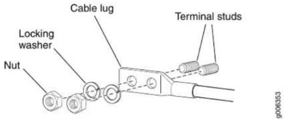
-
Loosen the captive screws on the cable restraint on the right edge of the power supply faceplate.
-
Route the DC power cables through the cable restraint.
-
Tighten the cable restraint captive screws to hold the power cables in place.
-
Verify that the power cabling is correct, that the power cables do not touch or block access to other hardware components, and that they do not drape where people could trip on them.
- Replace the clear plastic cover over the terminal studs on the faceplate.
- Switch on the customer site circuit breakers to provide voltage to the DC power source cables.
- Verify that the INPUT PRESENT LEDs on the power supply faceplate are lit steadily, indicating that the inputs are receiving power.
- Switch the power switch on the power supply to the ON position (I). The DC OK LED blinks momentarily, then lights steadily.

NOTE: After a power supply is powered on, it can take up to 60 seconds forstatus indicators—such as the LEDs on the powersupply, the command output displays, and messages on the LED display on the craftinterface—to indicate that the power supply is functioning normally. Ignore error indicators that appear during the first 60 seconds.
- Verify that the DC OK LED on the power supply faceplate is lit steadily, indicating that the power supply is correctly installed and is functioning properly.
Related Documentation
T1600 Power System Description on page 105.
- Maintaining the T1600 Power Supplies on page 490
•Troubleshooting the T1600 Power System on page 516
•T1600 Preventing Electrostatic Discharge Damage on page 552
•T1600 General Electrical Safety Guidelines on page 575
Replacing a T1600 DC Power Supply Cable on a Six-Input DC Power Supply
- Removing a T1600 DC Power Supply Cable From a Six-Input DC Power Supply on page 421
- Installing a T1600 DC Power Supply Cable on a Six-Input DC Power Supply on page 422
Removing a T1600 DC Power Supply Cable From a Six-Input DC Power Supply
To remove a DC power supply cable from a six-input DC power supply:
-
Switch off the customer site circuit breakers for all the cables attached to the power supply. Make sure that the voltage across the DC power source cable leads is 0 V and that there is no chance that the cables might become active during the removal process.
-
Remove the power cable from the external DC power source.
-
Remove the clear plastic cover protecting the terminal studs on the faceplate.
-
Remove the nut and washer from the terminal stud on the power supply (see Figure 218 on page 422). Use a 7/16-in. (11 mm) nut driver.
Figure 218: Disconnecting the DC Power Cable

- Remove the cable lug from the terminal stud on the power supply.
- Loosen the captive screw or screws on the cable restraint on the right edge of the power supply faceplate.
- Carefully move the power cable out of the way.
Installing a T1600 DC Power Supply Cable on a Six-Input DC Power Supply
To install a DC power supply cable on a six-input DC power supply:
- Locate a DC power cable that meets the specifications for the power supply.

CAUTION: A licensed electrician must attach a cable lug to the power cable that you supply. A cable with an incorrectly attached lug can damage the router.
- Route the power cable through the appropriate cable restraint.
- Attach the lug on the DC source power cable to the terminal stud.
a. Attach a negative (−) DC source power cable lug to the −48V (input) terminals.
b. Attach a positive (+) DC source power cable lug to the RET (return) terminals.
Secure the cable lug to the terminal stud, first with a washer, then with a nut (see Figure 219 on page 423). Use a 7/16-in. (11-mm) nut driver to tighten the nut. Apply between 23 lb-in. (2.6 Nm) and 25 lb-in. (2.8 Nm) of torque to each nut.

CAUTION: You must use an appropriate torque-controlled tool to tighten the nuts. Applying excessive torque damages the terminal studs and the power supply. The absolute maximum torque that may be applied to this nut is 45 lb-in. (5.0 Nm).
Figure 219: Connecting the DC Power Cable
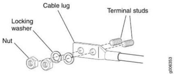
- Tighten the cable restraint captive screw or screws to hold the power cable in place.
- Replace the clear plastic cover over the terminal studs on the faceplate.
- Verify that the DC source power cabling is correct, that the power cable is not touching or blocking access to router components, and that it does not drape where people could trip on it.
- Attach the other end of the power cable to the external DC power source.
- Switch on the customer site circuit breakers.
- Verify that the INPUT PRESENT LEDs on the power supply faceplate are lit steadily, indicating that the inputs are receiving voltage.
- Switch the power switch on the power supply to the ON position (I). The DC OK LED blinks momentarily, then lights steadily.

NOTE: After a power supply is powered on, it can take up to 60 seconds forstatus indicators—such as the LEDs on the power supply, the command output displays, and messages on the LED display on the craft interface—to indicate that the power supply is functioning normally. Ignore error indicators that appear during the first 60 seconds.
- Verify that the DC OK LED on the power supply faceplate is lit steadily, indicating that the power supply is correctly installed and is functioning properly.
Related Documentation
T1600 Power System Description on page 105.
- Maintaining the T1600 Power Supplies on page 490
•Troubleshooting the T1600 Power System on page 516
•T1600 Preventing Electrostatic Discharge Damage on page 552
•T1600 General Electrical Safety Guidelines on page 575
Replacing a T1600 Six-Input DC Power Supply Front Air Filter
- Removing a T1600 Six-Input DC Power Supply Front Air Filter on page 424
- Installing a T1600 Six-Input DC Power Supply Front Air Filter on page 424
Removing a T1600 Six-Input DC Power Supply Front Air Filter
To remove a six-input DC power supply :
- Attach an electrostatic discharge (ESD) grounding strap to your bare wrist, and connect the strap to one of the ESD points on the chassis.
- Grasp the filter cover on the power supply faceplate, and pull it straight off the power supply.
- Remove the air filter.
Installing a T1600 Six-Input DC Power Supply Front Air Filter
To install a six-input DC power supply front filter element:
- Attach an electrostatic discharge (ESD) grounding strap to your bare wrist, and connect the strap to one of the ESD points on the chassis.
- Install a new filter element.
- Press the filter cover straight onto the power supply faceplate until all four sides click into place.
Related Documentation
T1600 Cooling System Description on page 37.
•Routine Maintenance Procedures for the T1600 Router on page 473
- Maintaining the T1600 Air Filters on page 476
•Replacing a T1600 Six-Input DC Power Supply Side Air Filter on page 424
•T1600 Preventing Electrostatic Discharge Damage on page 552
Replacing a T1600 Six-Input DC Power Supply Side Air Filter
- Removing a T1600 Six-Input DC Power Supply Side Air Filter on page 424
- Installing a T1600 Six-Input DC Power Supply Side Air Filter on page 425
Removing a T1600 Six-Input DC Power Supply Side Air Filter
To remove a six-input DC power supply side air filter element:
- Attach an electrostatic discharge (ESD) grounding strap to your bare wrist, and connect the strap to one of the ESD points on the chassis.
- Loosen the captive screw.
- Slide the air filter cover until the two lances leave the sheet metal.
- Remove the air filter cover hooks from the rectangle holes in the sheet metal.
- Remove the side air filter element from the air filter cover.
Figure 220: Removing the Power Supply Side Air Filter


Installing a T1600 Six-Input DC Power Supply Side Air Filter
To install a six-input DC power supply side air filter element:
- Attach an electrostatic discharge (ESD) grounding strap to your bare wrist, and connect the strap to one of the ESD points on the chassis.
- Install a new side filter element into the side air filter cover.
- Insert the side air filter cover hooks into the rectangle holes in the sheet metal.
- Slide the side air filter cover back into the power supply faceplate. The two lances insert into the sheet metal.
- Tighten the captive screw.
Figure 221: Installing the Power Supply Side Air Filter

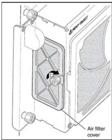
Related Documentation
T1600 Cooling System Description on page 37.
•Routine Maintenance Procedures for the T1600 Router on page 473
- Maintaining the T1600 Air Filters on page 476
•Replacing a T1600 Six-Input DC Power Supply Front Air Filter on page 423
•T1600 Preventing Electrostatic Discharge Damage on page 552
Replacing a T1600 Three-Phase Delta AC Power Supply
The T1600 router has either one nonredundant power supply or two redundant, load-sharing power supplies. Each redundant power supply is hot-insertable and hot-removable. When a redundant power supply is powered down or removed, the other power supply automatically assumes the entire electrical load for the router. If you have only one power supply, you must power off the system before removing the power supply.
- Removing a T1600 Three-Phase Delta AC Power Supply on page 426
- Installing a T1600 Three-Phase Delta AC Power Supply on page 430
Removing a T1600 Three-Phase Delta AC Power Supply
To remove a three-phase delta AC power supply:
- Switch off the customer site circuit breakers to the power supply being removed. Make sure that the voltage across the AC power source cord is 0 V and that there is no chance that the cord might become active during the removal process.
- Attach an electrostatic discharge (ESD) grounding strap to your bare wrist, and connect the strap to one of the ESD points on the chassis.
- Switch the power switch on the power supply faceplate to the standby position.

NOTE: After powering off a power supply, wait at least 60 seconds before turning it back on.
- Remove the ESD grounding strap from the ESD point on the chassis, and attach it to an approved site ESD grounding point. See the instructions for your site.
- Disconnect the AC power cord (see Figure 222 on page 427) from the power source.
Figure 222: Three-Phase Delta AC Power Supply

natural_image
Technical line drawing of two types of electrical connectors: a wire with black, gray, and green wires connected to a terminal block (no text or symbols)-
Remove the ESD grounding strap from the approved site ESD grounding point. See the instructions for your site. Reconnect the strap to one of the ESD points on the chassis.
-
Using a number 2 Phillips (+) screwdriver, loosen the two screws on the door of the metal wiring compartment that protects the AC terminal block.
-
Open the door of the metal wiring compartment.
-
Disconnect the wires from the AC terminal block on the three-phase delta AC power supply (Figure 223 on page 428), loosen each of the input terminals or grounding point screws, and remove each wire from the grounding point or input terminal.

NOTE: Theterminal connections have either slotted screws or hexscrews. Use a 1/4-in. slotted screwdriver for the slotted screws. Use a 5/32-in (4-mm) Allen wrench for the 5/16-in hex screws.
a. Remove the wire labeled L3 from the L3 input terminal.
b. Remove the wire labeled L2 from the L2 input terminal.
c. Remove the wire labeled L1 from the L1 input terminal.
d. Remove the wire labeled GND from the grounding point labeled GND.
Figure 223: Disconnecting the Power Cord from a Three-Phase Delta AC Power Supply

- Loosen the plastic cable tie fastening the AC power cord to the power supply.
- Loosen and remove the retaining nut from the AC power cord.
- Pull the AC power cord out of the metal wiring compartment.
- Carefully move the AC power cable out of the way.
-
Disconnect the AC power cord from the AC power supply.
-
Loosen the captive screws on the lower corners of the power supply faceplate completely.
-
Twist the ejector handles on the upper corners of the faceplate counterclockwise to unseat the power supply.
-
Grasp the handle on the power supply faceplate and pull firmly. Slide it halfway out of the chassis (see Figure 224 on page 429).

CAUTION: Each three-phased delta AC powers supply weighs approximately 31.0 lb (14.06 kg). Be prepared to support the full weight of the power supply as you remove it from the router.
- Place one hand underneath the power supply to support it and slide it completely out of the chassis.
Figure 224: Removing a Three-Phase Delta AC Power Supply

natural_image
Technical line drawing of an internal server rack with fans and connected cables (no text or symbols)
WARNING: Do not touch the power connectors on the rear of the power supply (see Figure 225 on page430). They can contain dangerous voltages.
Figure 225: Rear of the Power Supply Showing Midplane Connectors

natural_image
Line drawing of a rectangular electronic device casing with internal components and mounting holes (no text or symbols)Installing a T1600 Three-Phase Delta AC Power Supply
Each three-phase delta AC power supply weighs approximately 31.0 lb (14.06 kg). To install a three-phase delta AC power supply:
- Make sure that the voltage across the AC power source cord leads is 0 V and that there is no chance that the cord might become active during installation.
- Attach an electrostatic discharge (ESD) grounding strap to your bare wrist, and connect the strap to one of the ESD points on the chassis.
- Switch the power switch on the power supply faceplate to the standby position.
- Using both hands, slide the power supply into the chassis until you feel resistance (see Figure 227 on page 432).
- Twist the ejector handles at the upper corners of the power supply faceplate clockwise until they stop.
- Tighten the captive screws at the lower corners of the power supply faceplate to secure the power supply in the chassis.
- Using a number 2 Phillips (+) screwdriver, loosen the two screws on the door of the metal wiring compartment that protects the AC terminal block.
- Open the door of the metal wiring compartment.
- Unscrew the retaining nut from the AC power cord.
- Place the retaining nut inside the metal wiring compartment.
- Put the wires of the AC power cord through the hole of the metal wiring compartment.
-
Screw the retaining nut onto the AC power cord to secure it to the metal wiring compartment.
-
Connect the wires to the AC terminal block on the three-phase delta AC power supply (Figure 226 on page 431). Loosen each of the input terminal or grounding point screws, insert the wire into the grounding point or input terminal, and tighten the screw.

NOTE: Theterminal connections have either slotted screw or hex screws. Use a 1/4-in. slotted screwdriver for the slotted screws. Use a 5/32-in (4-mm) Allen wrench for the 5/16-in hex screws.
a. Insert the wire labeled GND into the grounding point labeled GND.
b. Insert the wire labeled L1 into the L1 input terminal
c. Insert the wire labeled L2 into the L2 input terminal.
d. Insert the wire labeled LC3 into the LC3 input terminal.
Figure 226: Connecting Power to a Three-Phase Delta AC Power Supply

- Verify that the power cord wire connections are correct.
- Using a number 2 Phillips (+) screwdriver, tighten the two captive screws on the metal AC wiring compartment.
- Verify that the AC power cord is not touching or blocking access to router components, and that it does not drape where people could trip on it.
-
Remove the ESD grounding strap from the ESD points on the chassis. Connect the strap to an approved site ESD grounding point. See the instructions for your site.
-
Connect the AC power cord plug to the power source.
- Switch on the customer site circuit breakers to provide voltage to the AC power cord.
- Remove the ESD grounding strap from the approved site ESD grounding point. See the instructions for your site. Reconnect the strap to one of the ESD points on the chassis.
- Verify that the AC OK LED on the power supply faceplate is lit steadily, indicating that the AC terminal block is receiving power.
- Switch the power switch on the power supply to the ON position (I) to provide power to the router components.
- Verify that the DC OK LED on the power supply faceplate is lit steadily, indicating that the power supply is correctly installed and is functioning properly. The DC OK LED blinks momentarily, then lights steadily.

NOTE: After a power supply is powered on, it can take up to 60 seconds forstatus indicators—such as the LEDs on the powersupply, the command output displays, and messages on the LED display on the craftinterface—to indicate that the power supply is functioning normally. Ignore error indicators that appear during the first 60 seconds.
Figure 227: Installing a Three-Phase Delta AC Power Supply
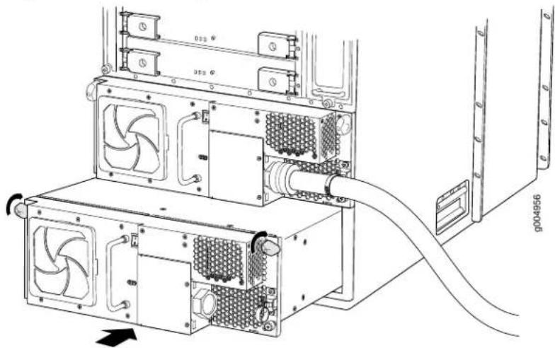
natural_image
Technical line drawing of a server rack with cooling fans and connected cables (no text or symbols)Related Documentation
T1600 Three-Phase Delta and Wye AC Power Supply Description on page 114.
•T1600 Three-Phase Delta and Wye AC Power Supply LEDs on page 117
•Troubleshooting the T1600 Power System on page 516
•T1600 Preventing Electrostatic Discharge Damage on page 552
Replacing a T1600 Three-Phase Delta AC Power Supply Cord
The T1600 router has either one nonredundant power supply or two redundant, load-sharing power supplies. An AC power supply cord on a redundant power supply is hot-insertable and hot-removable. When a redundant power supply is powered down, the other power supply automatically assumes the entire electrical load for the router. If you have only one power supply, you must power off the system before removing the AC power supply cord.
- Removing a T1600 Three-Phase Delta AC Power Supply Cord on page 433
- Installing a T1600 Three-Phase Delta AC Power Supply Cord on page 436
Removing a T1600 Three-Phase Delta AC Power Supply Cord
To remove a three-phase delta AC power supply cord:
- Switch off the customer site circuit breakers to the power supply being removed. Make sure that the voltage across the AC power source cord is 0 V and that there is no chance that the cord might become active during the removal process.
- Attach an electrostatic discharge (ESD) grounding strap to your bare wrist, and connect the strap to one of the ESD points on the chassis.
- Switch the power switch on the power supply faceplate to the standby position.

NOTE: After powering off a power supply, wait at least 60 seconds before turning it back on.
- Remove the ESD grounding strap from the ESD point on the chassis, and attach it to an approved site ESD grounding point. See the instructions for your site.
- Disconnect the AC power cord (see Figure 228 on page 433 from the power source.
Figure 228: Three-Phase Delta AC Power Supply

natural_image
Technical line drawing of two types of electrical connectors: a wire connector with black, gray, and beige wires and a multi-pin connector (no text or symbols)- Remove the ESD grounding strap from the approved site ESD grounding point. See the instructions for your site. Reconnect the strap to one of the ESD points on the chassis.
- Using a number 2 Phillips (+) screwdriver, loosen the two screws on the door of the metal wiring compartment that protects the AC terminal block.
-
Open the door of the metal wiring compartment.
-
Disconnect the wires from the AC terminal block on the three-phase delta AC power supply (Figure 229 on page 435). Loosen each of the input terminals or grounding point screws, and remove each wire from the grounding point or input terminal.

NOTE: The terminal connections have either slotted screws or hex screws. Use a 1/4-in. slotted screwdriver for the slotted screws. Use a 5/32-in (4-mm) Allen wrench for the 5/16-in hex screws.
a. Remove the wire labeled L3 from the L3 input terminal.
b. Remove the wire labeled L2 from the L2 input terminal.
c. Remove the wire labeled L1 from the L1 input terminal.
d. Remove the wire labeled GND from the grounding point labeled GND.
Figure 229: Disconnecting the Power Cord from a Three-Phase Delta AC Power Supply

- Loosen the plastic cable tie fastening the AC power cord to the power supply.
- Loosen and remove the retaining nut from the AC power cord.
- Pull the AC power cord out of the metal wiring compartment.
- Carefully move the AC power cable out of the way.
- Disconnect the AC power cord from the AC power supply.
Installing a T1600 Three-Phase Delta AC Power Supply Cord
To install a three-phase delta AC power supply cord:
- Make sure that the voltage across the AC power source cord leads is 0 V and that there is no chance that the cord might become active during installation.
- Attach an electrostatic discharge (ESD) grounding strap to your bare wrist, and connect the strap to one of the ESD points on the chassis.
- Switch the power switch on the power supply faceplate to the standby position.
- Using a number 2 Phillips (+) screwdriver, loosen the two screws on the door of the metal wiring compartment that protects the AC terminal block.
- Open the door of the metal wiring compartment.
- Unscrew the retaining nut from the AC power cord.
- Place the retaining nut inside the metal wiring compartment.
- Put the wires of the AC power cord through the hole of the metal wiring compartment.
-
Screw the retaining nut onto the AC power cord to secure it to the metal wiring compartment.
-
Insert the wires to the AC terminal block on the three-phase delta AC power supply (Figure 230 on page 437). Loosen each of the input terminal or grounding point screws, and insert the wire into the grounding point or input terminal.

NOTE: Theterminalconnections have either slotted screws or hex screws. Use a 1/4-in. slotted screwdriver for the slotted screws. Use a 5/32-in (4-mm) Allen wrench for the 5/16-in hex screws.
a. Insert the wire labeled GND into the grounding point labeled GND.
b. Insert the wire labeled L1 into the L1 input terminal
c. Insert the wire labeled L2 into the L2 input terminal.
d. Insert the wire labeled LC3 into the LC3 input terminal.
- Verify that the power cord wire connections are correct.
- Using a number 2 Phillips (+) screwdriver, tighten the two captive screws on the metal AC wiring compartment.
- Verify that the AC power cord is not touching or blocking access to router components, and that it does not drape where people could trip on it.
- Remove the ESD grounding strap from the ESD points on the chassis. Connect the strap to an approved site ESD grounding point. See the instructions for your site.
- Connect the AC power cord plug to the power source.
-
Switch on the customer site circuit breakers to provide voltage to the AC power cord.
-
Remove the ESD grounding strap from the approved site ESD grounding point. See the instructions for your site. Reconnect the strap to one of the ESD points on the chassis.
-
Verify that the AC OK LED on the power supply faceplate is lit steadily, indicating that the AC terminal block is receiving power.
-
Switch the power switch on the power supply to the ON position (I) to provide power to the router components.
-
Verify that the DC OK LED on the power supply faceplate is lit steadily, indicating that the power supply is correctly installed and is functioning properly. The DC OK LED blinks momentarily, then lights steadily.

NOTE: After a power supply is powered on, it can take up to 60 seconds forstatus indicators—such as the LEDson thepower supply, the command output displays, and messageson the LEDdisplay on the craft interface—to indicate that the power supply is functioning normally. Ignore error indicators that appear during the first 60 seconds.
Figure 230: Connecting Power to a Three-Phase Delta AC Power Supply

Related Documentation
T1600 Three-Phase Delta and Wye AC Power Supply Description on page 114.
•T1600 Three-Phase Delta and Wye AC Power Supply LEDs on page 117
•Troubleshooting the T1600 Power System on page 516
•T1600 Preventing Electrostatic Discharge Damage on page 552
•T1600 AC Power Cord Specifications on page 151
Replacing a T1600 Three-Phase Wye AC Power Supply
The T1600 router has either one nonredundant power supply or two redundant, load-sharing power supplies. Each redundant power supply is hot-insertable and hot-removable. When a redundant power supply is powered down or removed, the other power supply automatically assumes the entire electrical load for the router. If you have only one power supply, you must power off the system before removing the power supply.
- Removing a T1600 Three-Phase Wye AC Power Supply on page 438
- Installing a T1600 Three-Phase Wye AC Power Supply on page 441
Removing a T1600 Three-Phase Wye AC Power Supply
To remove a three-phase wye AC power supply:
- Switch off the customer site circuit breakers to the power supply being removed. Make sure that the voltage across the AC power source cord is 0 V and that there is no chance that the power cord might become active during the removal process.
- Attach an electrostatic discharge (ESD) grounding strap to your bare wrist, and connect the strap to one of the ESD points on the chassis.
- Switch the power switch on the power supply faceplate to the standby position.

NOTE: After powering off a power supply, wait at least 60 seconds before turning it back on.
- Remove the ESD grounding strap from the ESD point on the chassis, and attach it to an approved site ESD grounding point. See the instructions for your site.
- Disconnect the AC power cord (see Figure 231 on page 439) from the power source.
Figure 231: Three-Phase Wye AC Power Supply

natural_image
Technical line drawing of a multi-core cable connector with two views: top shows wire routing, bottom shows internal wiring (no text or symbols)-
Remove the ESD grounding strap from the approved site ESD grounding point. See the instructions for your site. Reconnect the strap to one of the ESD points on the chassis.
-
Using a number 2 Phillips (+) screwdriver, unscrew the two screws on the metal cover protecting the AC terminal block.
-
Disconnect the wires from the AC terminal block and grounding point on the three-phase wye AC power supply (Figure 232 on page 440), loosen each screw, and remove each wire from the grounding point or input terminal.

NOTE: Theterminalconnections have either slotted screws or hexscrews. Use a 1/4-in. slotted screwdriver for the slotted screws. Use a 5/32-in (4-mm) Allen wrench for the 5/16-in hex screws.
a. Remove the wire labeled N from the N input terminal
b. Remove the wire labeled L3 from the L3 input terminal.
c. Remove the wire labeled L2 from the L2 input terminal.
d. Remove the wire labeled L1 from the L1 input terminal.
e. Remove the wire labeled GND from the grounding point labeled GND.
Figure 232: Disconnecting the AC Power Cord from a Three-Phase Wye AC Power Supply
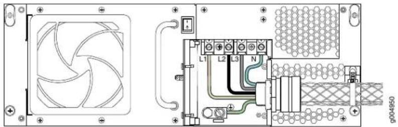
- Loosen the plastic cable tie fastening the AC power cord to the power supply.
- Loosen and remove the retaining nut from the AC power cord.
- Pull the AC power cord out of the metal wiring compartment.
- Carefully move the AC power cable out of the way.
- Loosen the captive screws on the lower corners of the power supply faceplate completely.
- Twist the ejector handles on the upper corners of the faceplate counterclockwise to unseat the power supply.
- Grasp the handle on the power supply faceplate and pull firmly. Slide it halfway out of the chassis (see Figure 233 on page 441).

CAUTION: Each three-phase wye AC power supply weighs approximately 31.0 lb (14.06 kg). Be prepared to support the full weight of the power supply as you remove it from the router.
- Place one hand underneath the power supply to support it and slide it completely out of the chassis.
Figure 233: Removing a Three-Phase Wye AC Power Supply

natural_image
Technical line drawing of an internal server rack with fans and connected cables (no text or symbols)Installing a T1600 Three-Phase Wye AC Power Supply
Each three-phase wye AC power supply weighs approximately 31.0 lb (14.06 kg). To install a three-phase wye AC power supply:
- Make sure that the voltage across the AC power cord leads is 0 V and that there is no chance that the power cord might become active during installation.
- Attach an electrostatic discharge (ESD) grounding strap to your bare wrist, and connect the strap to one of the ESD points on the chassis.
- Switch the power switch on the power supply faceplate to the standby position.
- Using both hands, slide the power supply into the chassis until you feel resistance (see Figure 235 on page 443).
- Twist the ejector handles at the upper corners of the power supply faceplate clockwise until they stop.
- Tighten the captive screws at the lower corners of the power supply faceplate to secure the power supply in the chassis.
- Using a slotted screwdriver, loosen the two screws securing the door of the metal wiring compartment.
- Open the door of the metal wiring compartment.
-
Place the retaining screw into the metal wiring compartment.
-
Unscrew the retaining nut from the AC power cord.
- Place the retaining nut inside the metal wiring compartment.
- Put the wires of the AC power cord through the hole of the metal wiring compartment.
- Screw the retaining nut onto the AC power cord to secure it to the metal wiring compartment.
- Connect the AC power cord wires to ground and the AC terminal block on the three-phase wye AC power supply (Figure 234 on page 442). Loosen each of the input terminals or grounding point screws, insert each wire into the grounding point or input terminal, and tighten the screw.

NOTE: Theterminal connections have either slotted screws or hexscrews. Use a 1/4-in. slotted screwdriver for the slotted screws. Use a 5/32-in (4-mm) Allen wrench for the 5/16-in hex screws.
a. Insert the wire labeled GND into the grounding point labeled GND.
b. Insert the wire L1 into the L1 input terminal.
c. Insert the wire labeled L2 into the L2 input terminal.
d. Insert the wire labeled L3 into the L3 input terminal.
e. Insert the wire labeled N into the N input terminal
Figure 234: Connecting Power to the Three-Phase Wye AC Power Supply
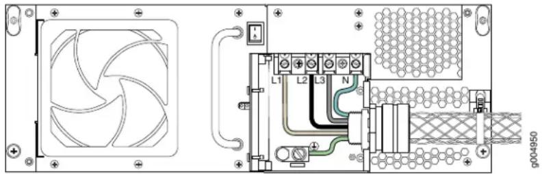
- Verify that the power cord wire connections are correct.
- Using a number 2 Phillips (+) screwdriver, tighten the two captive screws on the metal AC wiring compartment.
- Place the AC power cord into the plastic tie located on the right side of the power supply, and fasten the plastic tie.
- Verify that the AC power cord is not touching or blocking access to router components, and that it does not drape where people could trip on it.
- Remove the ESD grounding strap from the ESD points on the chassis. Connect the strap to an approved site ESD grounding point. See the instructions for your site.
-
Connect the AC power cord to the AC power source.
-
Switch on the customer site circuit breakers to provide voltage to the AC power source cables.
- Remove the ESD grounding strap from the approved site ESD grounding point. See the instructions for your site. Reconnect the strap to one of the ESD points on the chassis.
- Verify that the AC OK LED on the power supply faceplate is lit steadily, indicating that the AC terminal block is receiving power.
- Switch the power switch on the power supply to the ON position (I).
- Verify that the DC OK LED on the power supply faceplate is lit steadily, indicating that the power supply is correctly installed and is functioning properly. The DC OK LED blinks momentarily, then lights steadily.

NOTE: After a power supply is powered on, it can take up to 60 seconds forstatusindicators—such as the LEDs on the power supply, the command output displays, and messages on the LED display on the craft interface—to indicate that the power supply is functioning normally. Ignore error indicators that appear during the first 60 seconds.
Figure 235: Installing a Three-Phase Wye AC Power Supply
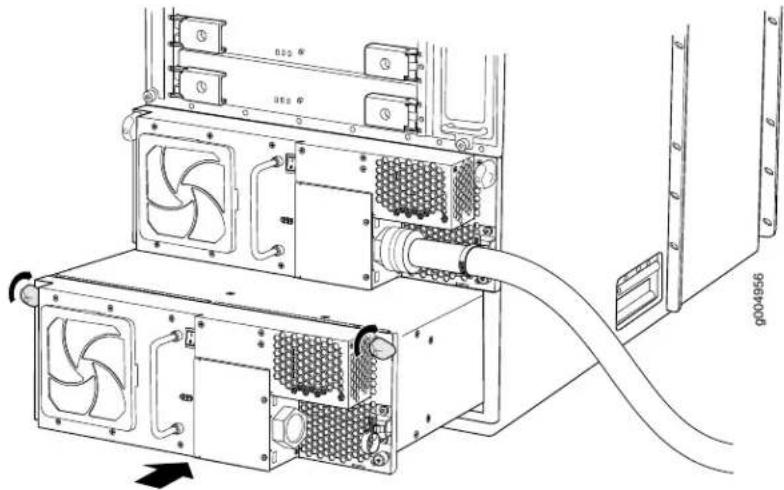
natural_image
Technical line drawing of a server rack with cooling fans and connected cables (no text or symbols)Related Documentation
T1600 Three-Phase Delta and Wye AC Power Supply Description on page 114.
•T1600 Three-Phase Delta and Wye AC Power Supply LEDs on page 117
•Troubleshooting the T1600 Power System on page 516
•T1600 Preventing Electrostatic Discharge Damage on page 552
•T1600 AC Power Cord Specifications on page 151
Replacing a T1600 Three-Phase Wye AC Power Supply Cord
The T1600 router has either one nonredundant power supply or two redundant, load-sharing power supplies. An AC power supply cord on a redundant power supply is hot-insertable and hot-removable. When a redundant power supply is powered down, the other power supply automatically assumes the entire electrical load for the router. If you have only one power supply, you must power off the system before removing the AC power supply cord.
- Removing a T1600 Three-Phase Wye AC Power Supply Cord on page 444
- Installing a T1600 Three-Phase Wye AC Power Supply Cord on page 446
Removing a T1600 Three-Phase Wye AC Power Supply Cord
To remove a three-phase wye AC power supply cord:
- Switch off the customer site circuit breakers to the power supply being removed. Make sure that the voltage across the AC power source cord is 0 V and that there is no chance that the power cord might become active during the removal process.
- Attach an electrostatic discharge (ESD) grounding strap to your bare wrist, and connect the strap to one of the ESD points on the chassis.
- Switch the power switch on the power supply faceplate to the standby position.

NOTE: After powering off a power supply, wait at least 60 seconds before turning it back on.
- Remove the ESD grounding strap from the ESD point on the chassis, and attach it to an approved site ESD grounding point. See the instructions for your site.
- Disconnect the AC power cord (see Figure 236 on page 444) from the power source.
Figure 236: Three-Phase Wye AC Power Supply
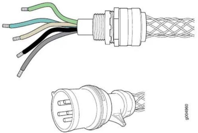
natural_image
Technical line drawing of a multi-core cable with exposed wires and connectors, plus a close-up of its internal structure (no text or symbols)-
Remove the ESD grounding strap from the approved site ESD grounding point. See the instructions for your site. Reconnect the strap to one of the ESD points on the chassis.
-
Using a number 2 Phillips (+) screwdriver, unscrew the two screws on the metal cover protecting the AC terminal block.
-
Disconnect the wires from the AC terminal block and grounding point on the three-phase wye AC power supply (Figure 237 on page 445), loosen each screw, and remove each wire from the grounding point or input terminal.

NOTE: Theterminalconnections have either slotted screw or hex screws. Use a 1/4-in. slotted screwdriver for the slotted screws. Use a 5/32-in (4-mm) Allen wrench for the 5/16-in hex screws.
a. Remove the wire labeled N from the N input terminal
b. Remove the wire labeled L3 from the L3 input terminal.
c. Remove the wire labeled L2 from the L2 input terminal.
d. Remove the wire labeled L1 from the L1 input terminal.
e. Remove the wire labeled GND from the grounding point labeled GND.
Figure 237: Disconnecting the AC Power Cord from a Three-Phase Wye AC Power Supply

-
Loosen the plastic cable tie fastening the AC power cord to the power supply.
-
Loosen and remove the retaining nut from the AC power cord.
-
Pull the AC power cord out of the metal wiring compartment.
-
Carefully move the AC power cable out of the way.
Installing a T1600 Three-Phase Wye AC Power Supply Cord
To install a three-phase wye AC power supply cord:
- Make sure that the voltage across the AC power cord leads is 0 V and that there is no chance that the power cord might become active during installation.
- Attach an electrostatic discharge (ESD) grounding strap to your bare wrist, and connect the strap to one of the ESD points on the chassis.
- Switch the power switch on the power supply faceplate to the standby position.
- Using a slotted screwdriver, loosen the two screws securing the door of the metal wiring compartment.
- Open the door of the metal wiring compartment.
- Place the retaining screw into the metal wiring compartment.
- Unscrew the retaining nut from the AC power cord.
- Place the retaining nut inside the metal wiring compartment.
- Put the wires of the AC power cord through the hole of the metal wiring compartment.
-
Screw the retaining nut onto the AC power cord to secure it to the metal wiring compartment.
-
Connect the AC power cord wires to ground and the AC terminal block on the three-phase wye AC power supply (Figure 238 on page 447). Loosen each of the input terminals or grounding point screws, insert each wire into the grounding point or input terminal, and tighten the screw.

NOTE: Theterminal connections have either slotted screwsorhex screws. Use a 1/4-in. slotted screwdriver for the slotted screws. Use a 5/32-in (4-mm) Allen wrench for the 5/16-in hex screws.
b. Insert the wire L1 into the L1 input terminal.
c. Insert the wire labeled L2 into the L2 input terminal.
d. Insert the wire labeled L3 into the L3 input terminal.
e. Insert the wire labeled N into the N input terminal
a. Insert the wire labeled GND into the grounding point labeled GND.
Figure 238: Connecting Power to the Wye 3-Phase AC Power Supply
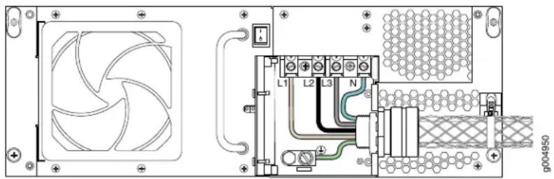
- Verify that the power cord wire connections are correct.
- Using a number 2 Phillips (+) screwdriver, tighten the two captive screws on the metal AC wiring compartment.
- Place the AC power cord into the plastic tie located on the right side of the power supply, and fasten the plastic tie.
- Verify that the AC power cord is not touching or blocking access to router components, and that it does not drape where people could trip on it.
- Remove the ESD grounding strap from the ESD points on the chassis. Connect the strap to an approved site ESD grounding point. See the instructions for your site.
- Connect the AC power cord to the AC power source.
- Switch on the customer site circuit breakers to provide voltage to the AC power source cables.
-
Remove the ESD grounding strap from the approved site ESD grounding point. See the instructions for your site. Reconnect the strap to one of the ESD points on the chassis.
-
Verify that the AC OK LED on the power supply faceplate is lit steadily, indicating that the AC terminal block is receiving power.
- Switch the power switch on the power supply to the ON position (I).
- Verify that the DC OK LED on the power supply faceplate is lit steadily, indicating that the power supply is correctly installed and is functioning properly. The DC OK LED blinks momentarily, then lights steadily.

NOTE: After a power supply is powered on, it can take up to 60 seconds forstatus indicators—such as the LEDs on the power supply, the command output displays, and messages on the LED display on the craft interface—to indicate that the power supply is functioning normally. Ignore error indicators that appear during the first 60 seconds.
Related Documentation
•T1600 Three-Phase Delta and Wye AC Power Supply Description on page 114
•T1600 Three-Phase Delta and Wye AC Power Supply LEDs on page 117
•Troubleshooting the T1600 Power System on page 516
•T1600 Preventing Electrostatic Discharge Damage on page 552
•T1600 AC Power Cord Specifications on page 151
CHAPTER 31
Replacing Switch Fabric Components
- Replacing a T1600-SIB on page 449
- Replacing a TXP-T1600 SIB on page 452
- Replacing a T1600 TXP-LCC-3D SIB on page 456
- Replacing a T1600 SFP on page 462
- Replacing a T1600 XFP on page 465
- Replacing a T1600 XENPAK Module on page 467
Replacing a T1600-SIB
- Removing a T1600-SIB on page 449
- Installing a T1600-SIB on page 450
- Verifying the Installation of a T1600-SIB on page 451
Removing a T1600-SIB
Five SIBs are installed in the router. The SIBs are located in the rear of the chassis in the slots marked SIB0 through SIB4. Each T1600-SIB weighs approximately 6.5 lb (3 kg).
To remove the SIBs (see Figure 239 on page 450):
- Place an electrostatic bag or antistatic mat on a flat, stable surface.
- Attach an electrostatic discharge (ESD) grounding strap to your bare wrist, and connect the strap to one of the ESD points on the chassis.
- Loosen the captive screws (using a Phillips (+) screwdriver, number 2) on the ejector handles on each side of the SIB faceplate.
- Flip the ejector handles outward to unseat the SIB.
- Grasp both ejector handles, pull firmly, and slide the SIB about three-quarters of the way out of the chassis.
- Place one hand underneath the SIB to support it and slide it completely out of the chassis. Place it on the antistatic mat.

CAUTION: Do not stack hardware components on one another after you remove them. Place each component on an antistatic mat resting on a stable, flat surface.
Figure 239: Removing a T1600-SIB

natural_image
Technical line drawing of an internal server rack unit with mounting brackets and indicator lights (no text or symbols)Installing a T1600-SIB
Each T1600-SIB weighs approximately 6.5 lb (3 kg). To install a T1600-SIB (see Figure 240 on page 451):
- Attach an electrostatic discharge (ESD) grounding strap to your bare wrist, and connect the strap to one of the ESD points on the chassis.
- Place one hand underneath the T1600-SIB to support it. With the other hand, hold one of the ejector handles on the T1600-SIB faceplate.
- Carefully align the sides of the T1600-SIB with the guides inside the chassis.
- Slide the T1600-SIB into the chassis, carefully ensuring that it is correctly aligned.
- Grasp both ejector handles and press them inward to seat the T1600-SIB. Ensure that the ejector handle tabs are properly mated inside their corresponding chassis slots. You might have to close and open the handles a few times before the tabs catch the slots.
-
Tighten the captive screws on the ejector handles.
-
Bring the T1600-SIB online using one of the following methods:
-
Press and hold the ONLINE/OFFLINE button on the T1600-SIB faceplate. The green OK LED on the faceplate begins to blink. Hold the button down until the LED blinks.
- Issue the following CLI command on the router:
user@host> request chassis sib online slot 0
Figure 240: Installing a T1600-SIB in a T1600
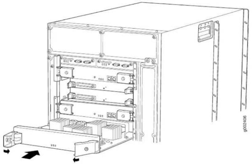
natural_image
Technical line drawing of an internal server rack unit with mounting ports and indicator lights (no text or symbols)Verifying the Installation of a T1600-SIB
To verify that the T1600-SIB is functioning normally:
- Check the LEDs on the T1600-SIB faceplate.
- The green OK LED should light steadily a few minutes after the T1600-SIB is installed.
- If the FAIL LED is lit steadily, remove and install the T1600-SIB again. Make sure that the T1600-SIB is seated properly. If the FAIL LED still lights steadily, the T1600-SIB is not functioning properly. Contact your customer support representative.
- Verify that four T1600-SIBs are in the Online state and one SIB is in the Spare state.
Display the status of the T1600-SIB by issuing the show chassis slbs command:
user@host> show chassis sibs
| Slot | State | Uptime |
| 0 | Spare | 0 days, 30 minutes, 12 seconds |
| 1 | Online | 0 days, 25 minutes, 45 seconds |
| 2 | Online | 0 days, 20 minutes, 28 seconds |
| 3 | Online | 0 days, 15 minutes, 7 seconds |
| 4 | Online | 0 days, 10 minutes, 52 seconds |
To bring a T1600-SIB online, issue the request chassis sib online operational mode command.
Related Documentation
T1600 Preventing Electrostatic Discharge Damage on page 552.
•Maintaining the T1600 SIBs on page 495
•T1600 Switch Interface Board (SIB) Description on page 119
Replacing a TXP-T1600 SIB
- Removing a TXP-T1600 SIB on page 452
- Installing a TXP-T1600 SIB on page 453
- Verifying the Installation of a TXP-T1600 SIB on page 455
Removing a TXP-T1600 SIB
Five SIBs are installed in the router. The SIBs are located in the rear of the chassis in the slots marked SIB0 through SIB4. Each TXP-T1600 SIB weighs 10.2 lb (4.6 kg).
To remove the TXP-T1600 SIBs (see Figure 241 on page 453):
- Place an electrostatic bag or antistatic mat on a flat, stable surface.
- Attach an electrostatic discharge (ESD) grounding strap to your bare wrist, and connect the strap to one of the ESD points on the chassis.
- Ensure the fiber-optic array cables connected to the TXP-T1600 SIB are labeled so you can reconnect them correctly.
- Use one of the following methods to take the TXP-T1600 SIB offline:
- Issue the request chassis sib lcc number slot slot-number offline command. For example:
user@host> request chassis sib lcc 0 slot 3 offline
Online initiated, use "show chassis sibs" to verify
- Press and hold the SIB ONLINE/OFFLINE button in the middle of the TXP-T1600 SIB faceplate to take the SIB offline. Hold the buttons down until all the LEDs on the faceplate are not lit.
- Remove all four fiber-optic array cables from the TXP-T1600 SIB.

WARNING: Do not look directly into a fiber-optic array port or a connector at the end of a fiber-optic array cable connected to a port. The fiber optics emit laser light that can damage your eyes.
- Install a dust cover on each cable you removed from the TXP-T1600 SIB. Align the dust cover with the cable and carefully press them together until they stop. The cover and the cable are keyed to ensure proper mating.
- Move the fiber-optic array cables to the side of the TXP-T1600 SIB so they do not interfere with the removal of the TXP-T1600 SIB.
- Loosen the captive screws (using a Phillips (+) screwdriver, number 2) on the ejector handles on each side of the SIB faceplate.
-
Flip the ejector handles outward to unseat the SIB.
-
Grasp both ejector handles, pull firmly, and slide the SIB about three-quarters of the way out of the chassis.
-
Place one hand underneath the SIB to support it and slide it completely out of the chassis. Place it on the antistatic mat.

CAUTION: Do not stack hardware components on one another after you remove them. Place each component on an antistatic mat resting on a stable, flat surface.
Figure 241: Removing a TXP-T1600 SIB

natural_image
Technical line drawing of an electronic device chassis showing internal components and mounting points (no text or symbols)Installing a TXP-T1600 SIB
Each TXP-T1600 SIB weighs approximately 10.2 lb (4.6 kg). To install a TXP-T1600 SIB (see Figure 242 on page 455):
- Attach an electrostatic discharge (ESD) grounding strap to your bare wrist, and connect the strap to one of the ESD points on the chassis.
- Place one hand underneath the TXP-T1600 SIB to support it. With the other hand, hold one of the ejector handles on the TXP-T1600 SIB faceplate.
- Carefully align the sides of the TXP-T1600 SIB with the guides inside the chassis.
- Slide the TXP-T1600 SIB into the chassis, carefully ensuring that it is correctly aligned.
- Grasp both ejector handles and press them inward to seat the TXP-T1600 SIB. Ensure that the ejector handle tabs are properly mated inside their corresponding chassis
slots. You might have to close and open the handles a few times before the tabs catch the slots.
- Tighten the captive screws on the ejector handles.
- Remove the dust cover from covering each TXP-F13 SIB fiber-optic array port.
- Remove the dust covers from the fiber-optic array cable connectors.
- Clean the fiber-optic array ports and cables.

CAUTION: While you replace a fiber-optic array cable, small deposits of oil, dust, and debris can enter the TXP-F13 SIB and TXP-T1600 SIB fiber-optic array ports, the fiber-optic array cables. We recommend that you clean the optics in these components, as well as the dust covers, immediately before connecting them.
- Connect each cable to its corresponding TXP-T1600 port. Align the cable with its corresponding TXP-T1600 SIB port and carefully press it into the port until it stops. The cable and port are keyed to ensure proper mating.

NOTE: The optics in a fiber-optic array port are spring loaded, so you must continue to apply force to a fiber-optic array cable or loopback connector while securing it to a TXP-T1600 SIB.
-
Bring the TXP-T1600 SIB online using one of the following methods:
-
Press and hold the ONLINE/OFFLINE button on the TXP-T1600 SIB faceplate. The green OK LED on the faceplate begins to blink. Hold the button down until the LED blinks.
- Issue the following CLI command on the router:
user@host> request chassis sib online slot 0
Figure 242: Installing a TXP-T1600 SIB
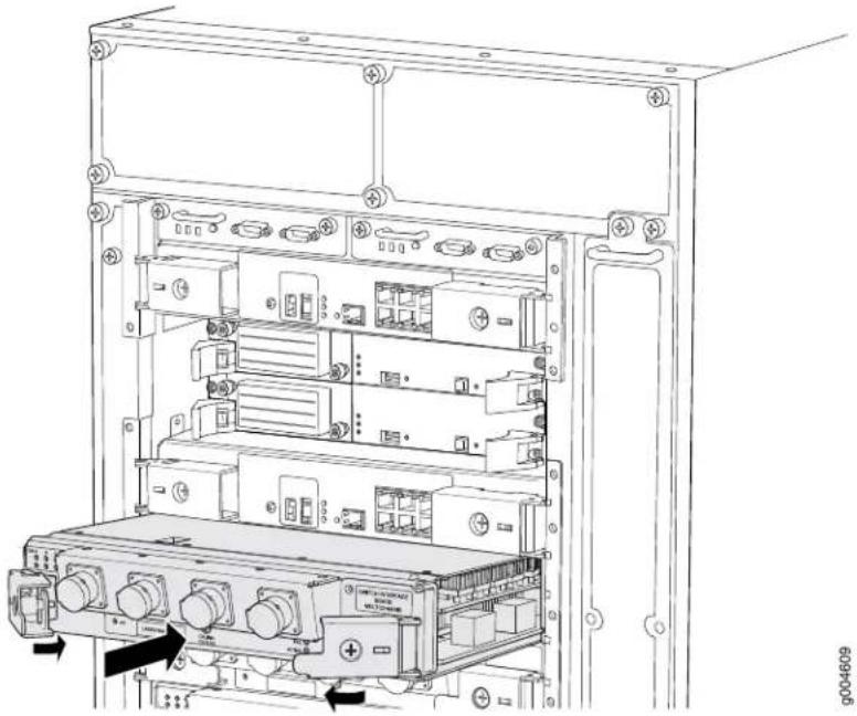
natural_image
Technical line drawing of an internal server rack with multiple ports and connectors (no text or symbols visible)Verifying the Installation of a TXP-T1600 SIB
To verify that the TXP-T1600 is functioning normally:
-
Check the LEDs on the TXP-T1600 faceplate. A few minutes after the TXP-T1600 is installed:
-
The green OK LED should light steadily, indicating that the TXP-T1600 SIB is installed correctly.
- The green LINK port LED should light steadily, indicating that the link between the TXP-F13 SIB port and the TXP-T1600 SIB port has been established successfully.
- The green RxPWR port LED should light steadily, indicating that full optical power is being received.
- The green OK LED should light steadily a few minutes after the TXP-T1600 is installed.
- If the FAIL LED is lit steadily, remove and install the TXP-T1600 again. Make sure that the TXP-T1600 is seated properly. If the FAIL LED still lights steadily, the TXP-T1600 is not functioning properly. Contact your customer support representative.
- Verify that four TXP-T1600s are in the Online state and one SIB is in the Spare state. Display the status of the TXP-T1600 by issuing the show chassis slbs command:
user@host> show chassis sibs
| Slot | State | Uptime |
| 0 | Spare | 0 days, 30 minutes, 12 seconds |
| 1 | Online | 0 days, 25 minutes, 45 seconds |
| 2 | Online | 0 days, 20 minutes, 28 seconds |
| 3 | Online | 0 days, 15 minutes, 7 seconds |
| 4 | Online | 0 days, 10 minutes, 52 seconds |
To bring a TXP-T1600 online, issue the request chassis sib online operational mode command.
Related Documentation
TXP-T1600 SIB Description on page 121.
•TXP-T1600 SIB LEDs on page 122
- Cleaning Fiber-Optic Array Components with the Dry Cloth Cleaning Tool on page 496
•T1600 Preventing Electrostatic Discharge Damage on page 552
Replacing a T1600 TXP-LCC-3D SIB
Five SIBs are located in the rear of the chassis in the slots marked SIB0 through SIB4. The TXP-LCC-3D SIBs connect to the TXP-F13-3D SIBs in a TX Matrix Plus router.
TXP-LCC-3D SIBs in active data switching planes are hot-pluggable. TXP-LCC-3D SIBs in a spare data switching planes are hot-insertable and hot-removable. When you remove a TXP-LCC-3D SIB in a spare switching plane, traffic forwarding continues without any degradation as long as the other four switching planes remain online. However, removing a TXP-LCC-3D SIB in an active switching plane might cause performance degradation in that switching plane. To avoid performance degradation, you can take the switching plane offline before you remove a TXP-LCC-3D SIB. For more information, see the TX Matrix Plus Router Hardware Guide
- Removing a T1600 TXP-LCC-3D SIB on page 456
- Installing a T4000 TXP-LCC-3D SIB on page 459
Removing a T1600 TXP-LCC-3D SIB
Each TXP-LCC-3D SIB weighs approximately 9.4 lb (4.2 kg). To remove a TXP-LCC-3D SIB (see Figure 246 on page 459):
- Place an electrostatic bag or antistatic mat on a flat, stable surface.
- Attach an electrostatic discharge (ESD) grounding strap to your bare wrist, and connect the strap to one of the ESD points on the chassis.
- Ensure that the cables connected to the TXP-3D-LCC SIB are labeled so you can reconnect them correctly.
- Use one of the following methods to take the TXP-LCC-3D SIB offline:
- Issue the request chassis sib lcc number slot slot-number offline command. For example:
user@host> request chassis slb lcc 0 slot 3 offline Online initiated, use "show chassis sibs" to verify
- Press and hold the SIB ONLINE/OFFLINE button in the middle of the TXP-LCC-3D SIB faceplate to take the SIB offline. Hold the buttons down until all the LEDs on the faceplate are not lit.
- Remove each switching plane cable from the SIB.
- CXP—Disconnect the CXP cables (Figure 243 on page 458) from the CXP transceivers. After all the CXP cables have been disconnected from the transceivers, remove the CXP transceivers (Figure 244 on page 458) from the SIB.

WARNING: Do not look directly into a CXP cable connected to a port. The fiber optics emit laser light that can damage your eyes.
- AOC—Remove the AOC transceivers from the SIB (Figure 245 on page 458).
- Install dust covers on the cables and transceivers that you removed. Align the dust cover with the cable or transceiver and carefully press them together until they stop. The dust cover and the cable or transceiver are keyed to ensure proper mating.
- CXP—Install a dust cover on each CXP transceiver and CXP cable.
- AOC—Install a dust cover on each AOC transceiver.
-
Move the cables to the side of the SIB so they do not interfere with the removal of the SIB.
-
Using a Phillips (+) screwdriver, number 2, loosen the captive screws on the ejector handles on each side of the SIB faceplate.
-
Flip the ejector handles outward to unseat the SIB.
-
Grasp both ejector handles, pull firmly, and slide the SIB about three-quarters of the way out of the chassis.
-
Place one hand underneath the SIB to support it, and slide it completely out of the chassis. Place it on the antistatic mat.

CAUTION: Do not stack hardware components on one another after you remove them. Place each component on an antistatic mat resting on a stable, flat surface.
Figure 243: CXP Cable and Dust Cover

Figure 244: CXP Transceiver and Dust Cover

Figure 245: AOC Transceiver and Dust Cover

Figure 246: Installing a TXP-LCC-3D SIB
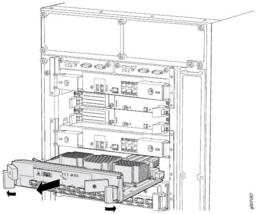
natural_image
Technical line drawing of an internal server rack with multiple ports and a base unit, showing no text or symbols.Installing a T4000 TXP-LCC-3D SIB
To install a TXP-LCC-3D SIB (see Figure 249 on page 462):
- Attach an electrostatic discharge (ESD) grounding strap to your bare wrist, and connect the strap to one of the ESD points on the chassis.
- Place one hand underneath the SIB to support it. With the other hand, hold one of the ejector handles on the SIB.
- Carefully align the sides of the SIB with the guides inside the chassis.
- Slide the SIB into the chassis, carefully ensuring that it is correctly aligned.
- Grasp both ejector handles, and press them inward to seat the SIB. Ensure that the ejector handle tabs are properly mated inside their corresponding chassis slots. You might have to close and open the handles a few times before the tabs catch the slots.
- Tighten the captive screws on the ejector handles.
- Remove the dust covers from the transceivers and cables. Store the dust covers in a dust-free resealable plastic bag.
- Insert the transceiver into the ports.
- CXP—Insert the CXP transceivers into the TXP-LCC-3D ports. The CXP transceivers and the port are keyed to ensure proper mating. After all the CXP transceiver have been installed, reconnect each CXP cable (Figure 247 on page 461) to the CXP transceiver in the TXP-LCC-3D port that corresponds to the label on the cable.
Align the cable with the port and carefully press it into the port until it your hear a click and it stops. The CXP cables and CXP transceivers are keyed to ensure proper mating.
- AOC—Using the cable labels, insert each AOC transceiver into its corresponding TXP-F13-3D port (Figure 248 on page 461).
Align the transceiver with the port and carefully press it into the port until it your hear a click and it stops. The AOC transceivers and the port are keyed to ensure proper mating.
- Bring the TXP-LCC-3D SIB online using one of the following methods:
- Press and hold the ONLINE/OFFLINE button on the TXP-LCC-3D SIB faceplate. The green OK LED on the faceplate begins to blink. Hold the button down until the LED blinks.
- Issue the following CLI command on the router: user@host> request chassis sib online slot 0
-
Check the LEDs on the TXP-LCC-3D SIB faceplate.
-
The green OK LED should light steadily a few minutes after the SIB is installed.
-
If the FAIL LED is lit steadily, remove and install the TXP-LCC-3D SIB again. Make sure that the SIB is seated properly. If the FAIL LED still lights steadily, the SIB is not functioning properly. Contact your customer support representative.
-
Verify that four SIBs are in the Online state and one SIB is in the Spare state. Display the status of the SIB by issuing the show chassis slbs command:
user@host> show chassis slbs
| Slot | State | Uptime |
| 0 | Spare | |
| 1 | Online | 1 day, 13 hours, 16 minutes, 49 seconds |
| 2 | Online | 1 day, 13 hours, 16 minutes, 33 seconds |
| 3 | Online | 1 day, 13 hours, 16 minutes, 16 seconds |
| 4 | Online | 1 day, 13 hours, 16 minutes |
If a SIB is not online, issue the request chassis slb online operational mode command.
Figure 247: Connecting a CXP Cable to a CXP Transceiver

Figure 248: Installing an AOC Transceiver
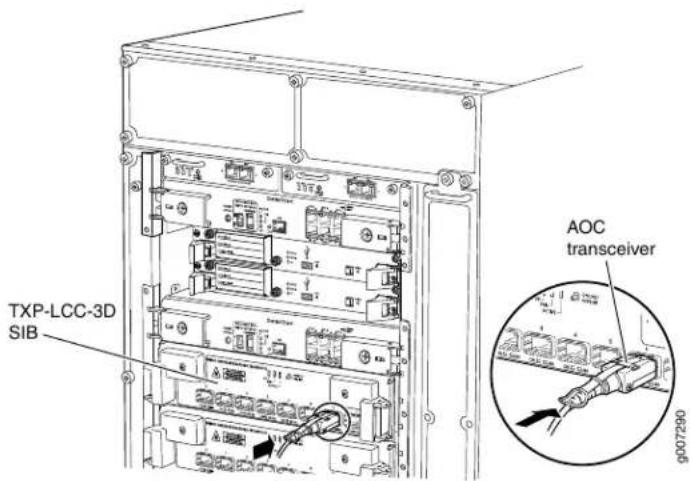
Figure 249: Installing a TXP-LCC-3D SIB

natural_image
Technical line drawing of an internal server rack with multiple ports and a central rack unit (no text or symbols visible)Related Documentation
T1600 TXP-LCC-3D SIB Description on page 123.
•Maintaining the T1600 SIBs on page 495
•Troubleshooting the T1600 SIBs on page 520
•T1600 Preventing Electrostatic Discharge Damage on page 552
Replacing a T1600 SFP
- Removing a T1600 SFP on page 463
- Installing a T1600 SFP on page 464
Removing a T1600 SFP
Small form-factor pluggables (SFPs) are transceivers that can be removed from a PIC. SFPs are hot-insertable and hot-removable. Removing an SFP does not interrupt PIC functioning, but the removed SFP no longer receives or transmits data.

NOTE: When you remove a PIC transceiver, the router continues to function, although the PIC interface being removed no longer functions.
Figure 250: Small Form-Factor Pluggable (SFP)


NOTE: This procedure applies to both SFP and SFP+ transceivers.
To remove an SFP transceiver (see Figure 250 on page 463):
- Place an electrostatic bag or antistatic mat on a flat, stable surface to receive the SFP. Have ready a rubber safety cap for the SFP transceiver and the cable.
- Attach an electrostatic discharge (ESD) grounding strap to your bare wrist, and connect the strap to one of the ESD points on the chassis.
- Label the cable connected to the SFP so that you can later reconnect it to the correct SFP.
- Disconnect the cable from the SFP. Immediately cover the transceiver and the end of the cable with a rubber safety cap.

WARNING: Do not look directly into a fiber-optic transceiver or into the ends of fiber-optic cables. Fiber-optic transceivers and fiber-optic cable connected to a transceiver emit laser light that can damage your eyes.

CAUTION: Do not leave a fiber-optic transceiver uncovered except when inserting or removing cable. The safety cap keeps the port clean and prevents accidental exposure to laser light.
- Arrange the cable in the cable management system to prevent it from dislodging or developing stress points. Secure the cable so that it is not supporting its own weight
as it hangs to the floor. Place excess cable out of the way in a neatly coiled loop in the cable management system. Placing fasteners on the loop helps to maintain its shape.

CAUTION: Avoid bending fiber-optic cable beyond its minimum bend radius. An arc smaller than a few inches in diameter can damage the cable and cause problems that are difficult to diagnose.
- Pull the ejector handle away from the SFP faceplate to unseat the SFP from the PIC. Pull the SFP out of the PIC, and place it on the antistatic mat or in the electrostatic bag.

CAUTION: After removing a transceiver from the chassis, wait at least 30 seconds before reinserting it or inserting a transceiver into a different slot.
Installing a T1600 SFP
To install a replacement SFP:
- Attach an electrostatic discharge (ESD) grounding strap to your bare wrist, and connect the strap to one of the ESD points on the chassis.
- Verify that a rubber safety cap covers the SFP transceiver, installing one if necessary.
-
Orient the SFP over the port in the PIC so that the connector end will enter the slot first and the SFP connector faces the appropriate direction:
-
If the PIC has ten SFP ports, the ports are arranged in two columns. The SFP connector faces to the right for ports in the left column, and to the left for ports in the right column.
-
If the PIC has one or two SFP ports, the SFP connector faces to the left.
-
Slide the SFP into the slot. If there is resistance, remove the SFP and flip it so that the connector faces the other direction.
- Remove the rubber safety cap from the transceiver and the end of the cable, and insert the cable into the transceiver.

WARNING: Do not look directly into a fiber-optic transceiver or into the ends of fiber-optic cables. Fiber-optic transceivers and fiber-optic cable connected to a transceiver emit laser light that can damage your eyes.

CAUTION: Do not leave a fiber-optic transceiver uncovered except when inserting or removing cable. The safety cap keeps the port clean and prevents accidental exposure to laser light.
- Arrange the cable in the cable management system to prevent the cable from dislodging or developing stress points. Secure the cable so that it is not supporting its own weight as it hangs to the floor. Place excess cable out of the way in a neatly coil loop in the cable management system. Placing fasteners on the loop helps to maintain its shape.

CAUTION: Do not let fiber-optic cable hang free from the connector. Do not allow fastened loops of cable to dangle, which stresses the cable at the fastening point.

CAUTION: Avoid bending fiber-optic cable beyond its minimum bend radius. An arc smaller than a few inches in diameter can damage the cable and cause problems that are difficult to diagnose.
- Verify that the status LEDs on the PIC faceplate indicate that the SFP is functioning correctly (there is an LED for each SFP port). For more information about the PIC LEDs, see the interface module reference for your device. You can also verify PIC functioning by issuing the show chassis fpc plc-status command.
Related Documentation
T1600 Preventing Electrostatic Discharge Damage on page 552.
•Replacing a T1600 PIC Cable on page 389
•T1600 General Laser Safety Guidelines on page 565
• Laser Safety Warnings for Juniper Networks Devices on page 566
Replacing a T1600 XFP
- Removing a T1600 XFP on page 465
- Installing a T1600 XFP on page 466
Removing a T1600 XFP
10-Gigabit small form-factor pluggables (XFPs) are hot-insertable and hot-removable. Removing an XFP does not interrupt PIC functioning, but the removed XFP no longer receives or transmits data.
To remove an XFP:
- Place an electrostatic bag or antistatic mat on a flat, stable surface to receive the XFP. Have ready a rubber safety cap for the XFP transceiver and the cable.
- Attach an electrostatic discharge (ESD) grounding strap to your bare wrist, and connect the strap to one of the ESD points on the chassis.
-
Label the cable connected to the XFP so that you can later reconnect it to the correct XFP.
-
Disconnect the cable from the XFP. Immediately cover the transceiver and the end of the cable with a rubber safety cap.

WARNING: Do not look directly into a fiber-optic transceiver or into the ends of fiber-optic cables. Fiber-optic transceivers and fiber-optic cable connected to a transceiver emit laser light that can damage your eyes.

CAUTION: Do not leave a fiber-optic transceiver uncovered except when inserting or removing cable. The safety cap keeps the port clean and prevents accidental exposure to laser light.
- Arrange the cable in the cable management system, to prevent it from dislodging or developing stress points. Secure the cable so that it is not supporting its own weight as it hangs to the floor. Place excess cable out of the way in a neatly coiled loop in the cable management system. Placing fasteners on the loop helps to maintain its shape.

CAUTION: Avoid bending fiber-optic cable beyond its minimum bend radius. An arc smaller than a few inches in diameter can damage the cable and cause problems that are difficult to diagnose.
- Pull the ejector handle away from the XFP faceplate to unseat the XFP from the PIC. Pull the XFP out of the PIC and place it on the antistatic mat or in the electrostatic bag.
Installing a T1600 XFP
To install a replacement XFP:
-
Attach an electrostatic discharge (ESD) grounding strap to your bare wrist, and connect the strap to one of the ESD points on the chassis.
-
Verify that a rubber safety cap covers the XFP transceiver, installing one if necessary.
-
Orient the XFP over the port in the PIC so that the connector end will enter the slot first and the XFP connector faces the appropriate direction.
-
Slide the XFP into the slot. If there is resistance, remove the XFP and flip it so that the connector faces the other direction.
-
Remove the rubber safety cap from the transceiver and the end of the cable, and insert the cable into the transceiver.

WARNING: Do not look directly into a fiber-optic transceiver or into the ends of fiber-optic cables. Fiber-optic transceivers and fiber-optic cable connected to a transceiver emit laser light that can damage your eyes..

CAUTION: Do not leave a fiber-optic transceiver uncovered except when inserting or removing cable. The safety cap keeps the port clean and prevents accidental exposure to laser light.
- Arrange the cable in the cable management system to prevent the cable from dislodging or developing stress points. Secure the cable so that it is not supporting its own weight as it hangs to the floor. Place excess cable out of the way in a neatly coil loop in the cable management system. Placing fasteners on the loop helps to maintain its shape.

CAUTION: Do not let fiber-optic cable hang free from the connector. Do not allow fastened loops of cable to dangle, which stresses the cable at the fastening point.

CAUTION: Avoid bending fiber-optic cable beyond its minimum bend radius. An arc smaller than a few inches in diameter can damage the cable and cause problems that are difficult to diagnose.
- Verify that the status LEDs on the PIC faceplate indicate that the XFP is functioning correctly (there is an LED for each XFP port). For more information about the PIC LEDs, see the T1600 Core Router Interface Module Reference. You can also verify PIC functioning by issuing the show chassis fpc pic-status command described in "Maintaining T1600 PICs and PIC Cables" on page 488.
Related Documentation
T1600 Preventing Electrostatic Discharge Damage on page 552.
•Replacing a T1600 PIC Cable on page 389
•T1600 General Laser Safety Guidelines on page 565
•Laser Safety Warnings for Juniper Networks Devices on page 566
Replacing a T1600 XENPAK Module
- Removing the T1600 XENPAK Module on page 468
- Installing the T1600 XENPAK Module on page 469
Removing the T1600 XENPAK Module
To remove a XENPAK module (see Figure 251 on page 469):
- Place an electrostatic bag or antistatic mat on a flat, stable surface to receive the XENPAK module. Have ready a rubber safety cap for the XENPAK transceiver and the cable.
- Attach an electrostatic discharge (ESD) grounding strap to your bare wrist, and connect the strap to one of the ESD points on the chassis.
- Label the cable connected to the XENPAK module so that you can later reconnect it to the correct module.
- Disconnect the cable from the XENPAK module. Immediately cover the transceiver and the end of the cable with a rubber safety cap.

WARNING: Do not look directly into a fiber-optic transceiver or into the ends of fiber-optic cables. Fiber-optic transceivers and fiber-optic cable connected to a transceiver emit laser light that can damage your eyes.

CAUTION: Do not leave a fiber-optic transceiver uncovered except when inserting or removing cable. The safety cap keeps the port clean and prevents accidental exposure to laser light.
- Arrange the cable in the cable management system to prevent it from dislodging or developing stress points. Secure the cable so that it is not supporting its own weight as it hangs to the floor. Place excess cable out of the way in a neatly coiled loop in the cable management system. Placing fasteners on the loop helps to maintain its shape.

CAUTION: Avoid bending fiber-optic cable beyond its minimum bend radius. An arc smaller than a few inches in diameter can damage the cable and cause problems that are difficult to diagnose.
-
Unscrew the thumbscrews at the top and bottom of the XENPAK module.
-
Slide the module out of the PIC and place it in the electrostatic bag or on the antistatic mat.
Figure 251: Removing a XENPAK Module

Installing the T1600 XENPAK Module
To install a replacement XENPAK module (see Figure 252 on page 470):
- Attach an electrostatic discharge (ESD) grounding strap to your bare wrist, and connect the strap to one of the ESD points on the chassis.
- Verify that a rubber safety cap covers the XENPAK transceiver. Install one if necessary.
- Orient the XENPAK module so that the optical port faces out, and the transmit (TX) port is above the receive (RX) port (see Figure 252 on page 470).
- Slide the XENPAK module into the slot.
- Tighten the thumbscrews at the top and bottom of the XENPAK module. Verify that the module is seated properly.
- Remove the rubber safety cap from the transceiver and the end of the cable. Insert the cable into the transceiver.

WARNING: Do not look directly into a fiber-optic transceiver or into the ends of fiber-optic cables. Fiber-optic transceivers and fiber-optic cable connected to a transceiver emit laser light that can damage your eyes.

CAUTION: Do not leave a fiber-optic transceiver uncovered except when inserting or removing cable. The safety cap keeps the port clean and prevents accidental exposure to laser light.
- Arrange the cable in the cable management system to prevent the cable from dislodging or developing stress points. Secure the cable so that it is not supporting its own weight as it hangs to the floor. Place excess cable out of the way in a neatly coil
loop in the cable management system. Placing fasteners on the loop helps to maintain its shape.

CAUTION: Do not let fiber-optic cable hang free from the connector. Do not allow fastened loops of cable to dangle, which stresses the cable at the fastening point.

CAUTION: Avoid bending fiber-optic cable beyond its minimum bend radius. An arc smaller than a few inches in diameter can damage the cable and cause problems that are difficult to diagnose.
- Verify that the status LEDs on the PIC faceplate indicate that the XENPAK module is functioning correctly. For more information about the PIC LEDs, see the interface module reference for your device. You can also verify PIC functioning by issuing the show chassis fpc pic-status command.
Figure 252: Installing a XENPAK Module

NOTE: Orient the XENPAK module in the slot so it does not touch the faceplate opening.
Related Documentation
•T1600 Preventing Electrostatic Discharge Damage on page 552
•Replacing a T1600 PIC Cable on page 389
•T1600 General Laser Safety Guidelines on page 565
• Laser Safety Warnings for Juniper Networks Devices on page 566
PART 5
Maintaining the Chassis and Component
• Routine Maintenance Procedures on page 473
- Maintaining Components on page 475
CHAPTER 32
Routine Maintenance Procedures
- Routine Maintenance Procedures for the T1600 Router on page 473
Routine Maintenance Procedures for the T1600 Router
Purpose For optimum router performance, perform preventive maintenance procedures.

NOTE: Some components, such as the Connector Interface Panel (CIP) and the craft interface, require no maintenance.
Action On a regular basis:
- Inspect the installation site for moisture, loose wires or cables, and excessive dust. Make sure that airflow is unobstructed around the router and into the air intake vents.
- Check the status-reporting devices on the craft interface: system alarms, LEDs, and LCD.
- Inspect the air filters at the bottom front and left rear of the router, replacing them every 6 months. Do not run the router for more than a few minutes without the air filter in place.
Related Documentation
•T1600 Craft Interface Description on page 31
- Maintaining the T1600 Air Filters on page 476
•T1600 Router Description on page 3
CHAPTER 33
Maintaining Components
- Tools and Parts Required to Maintain the T1600 Hardware Components on page 475
- Maintaining the T1600 Air Intake Vents on page 476
- Maintaining the T1600 Air Filters on page 476
- Maintaining the T1600 Control Boards on page 477
- Maintaining the T1600 Fan Trays on page 478
- Maintaining T1600 FPCs on page 480
• Holding T1600 FPCs on page 481
• Storing T1600 FPCs on page 485 - Maintaining the T1600 Host Subsystem on page 486
- Maintaining T1600 PICs and PIC Cables on page 488
- Maintaining the T1600 Power Supplies on page 490
- Maintaining the T1600 Routing Engines on page 493
- Maintaining the T1600 SCGs on page 495
- Maintaining the T1600 SIBs on page 495
- Cleaning Fiber-Optic Array Components with the Dry Cloth Cleaning Tool on page 496
Tools and Parts Required to Maintain the T1600 Hardware Components
To maintain the T320 hardware components, you need the following tools and parts:
• ESD grounding wrist strap
- Flat-blade (−) screwdriver
• Phillips (+) screwdriver, number 1
• Phillips (+) screwdriver, number 2
Related Documentation
Contacting Customer Support on page 529.
•Routine Maintenance Procedures for the T1600 Router on page 473
Maintaining the T1600 Air Intake Vents
Purpose For optimum cooling, verify the condition of the air intake vents. Dust can clog air intake vents, reducing cooling system efficiency.
Action On a regular basis, check the vents and clean them as necessary.
Related Documentation Clearance Requirements for Airflow and T1600 Hardware Maintenance on page 135. •T1600 Cooling System Description on page 37
Maintaining the T1600 Air Filters
Purpose For optimum cooling, verify the condition of the air filters.
Air filters for both the front and rear fan trays help keep dust and other particles from entering the cooling system. To function properly, the entire cooling system requires an unobstructed airflow and proper clearance around the site, as described in "Clearance Requirements for Airflow and T1600 Hardware Maintenance" on page 135.
Figure 253: Airflow Through the Chassis

Action Check the air filters regularly for dust and debris. The filter elements degrade over time, so the filter elements in use, must be replaced every 6 months. For procedures to replace the air filters, see "Replacing the T1600 Rear Air Filter" on page 307 and "Replacing the T1600 Front Air Filter" on page 305.
Use spare filter elements within one year of manufacture. Check the date of manufacture printed on the filter. Store spare filter elements in a dark, cool, and dry place. Storing the filter elements at higher temperatures, or where they can be exposed to ultraviolet (UV) radiation, hydrocarbon emissions, or vapors from solvents, can significantly reduce their life.

CAUTION: Always keep both air filters in place while the router is operating. Because the fans are very powerful, they could pull small bits of wire or other materials into the router through the unfiltered air intake. This could damage the router components.
Related Documentation
T1600 Cooling System Description on page 37.
Maintaining the T1600 Control Boards
Purpose For optimum router performance, verify the condition of the control boards.
Action On a regular basis:
- Check the host subsystem LEDs on the craft interface. For more information about the LEDs and the display, see "T1600 Craft Interface Description" on page 31.
During normal operations:
- The green host subsystem OK LED on the craft interface is lit.
- The red host subsystem OK LED on the craft interface is not lit.
- Check the LEDs on the control board faceplate.
During normal operations:
•The green OK LED on the control board faceplate is lit.
- The yellow FAIL LED on the control board faceplate is not lit.
- Issue the show chassis environment cb command to check the status of the T-CBs.
The output is similar to the following:
user@host> show chassis environment cb
| CB 0 status: | |
| State | Online Master |
| Temperature | 29 degrees C / 84 degrees F |
| Power: | |
| 1.8 V | 1809 mV |
| 2.5 V | 2496 mV |
| 3.3 V | 3295 mV |
| 4.6 V | 4687 mV |
| 5.0 V | 5042 mV |
| 12.0 V | 11985 mV |
| 3.3 V bias | 3277 mV |
| 8.0 V bias | 7472 mV |
| GBUS Revision | 40 |
| FPGA Revision | 7 |
For further description of the output from the commands, see show chassis environment cb.
Related Documentation
T1600 Control Boards Description on page 66.
•T1600 Chassis Description on page 19
•T1600 T-CB LEDs on page 68.
•T1600 LCC-CB LEDs on page 70
•Troubleshooting the T1600 Host Subsystems on page 510
Maintaining the T1600 Fan Trays
Purpose For optimum cooling, verify the condition of the fans.
Action On a regular basis:
- Monitor the status of the fans. The fan trays each contain multiple fans that work in unison to cool the router components. If one fan fails, the host subsystem adjusts the speed of the remaining fans to maintain proper cooling. A red alarm is triggered when a fan fails, and a yellow alarm is triggered when a fan tray is removed. During normal operation, the fans in each fan tray function at normal speed.
- To display the status of the fans, issue the show chassis environment or show chassis fan command.
For the standard fan trays, the output for the show chassis environment command is similar to the following:
user@host> show chassis environment
| Class Item | Status | Measurement | |
| Fans | Top Left Front fan | OK | Spinning at normal speed |
| Top Left Middle fan | OK | Spinning at normal speed | |
| Top Left Rear fan | OK | Spinning at normal speed | |
| Top Right Front fan | OK | Spinning at normal speed | |
| Top Right Middle fan | OK | Spinning at normal speed | |
| Top Right Rear fan | OK | Spinning at normal speed | |
| Bottom Left Front fan | OK | Spinning at normal speed | |
| Bottom Left Middle fan | OK | Spinning at normal speed | |
| Bottom Left Rear fan | OK | Spinning at normal speed | |
| Bottom Right Front fan | OK | Spinning at normal speed | |
| Bottom Right Middle fan | OK | Spinning at normal speed | |
| Bottom Right Rear fan | OK | Spinning at normal speed | |
| Rear Tray Top fan | OK | Spinning at normal speed | |
| Rear Tray Second fan | OK | Spinning at normal speed | |
| Rear Tray Third fan | OK | Spinning at normal speed | |
| Rear Tray Fourth fan | OK | Spinning at normal speed | |
| Rear Tray Fifth fan | OK | Spinning at normal speed | |
| Rear Tray Sixth fan | OK | Spinning at normal speed | |
| Rear Tray Seventh fan | OK | Spinning at normal speed | |
| Rear Tray Bottom fan | OK | Spinning at normal speed... | |
Top Left and Top Right refer to fans in the upper front fan tray. Bottom Left and Bottom Right refer to fans in the lower front fan tray. Rear refers to the fans in the rear fan tray.
For the quiet fan trays, the output for the show chassis environment command is similar to the following:
user@host> show chassis environment
| Class | Item | Status | Measurement |
| Fans | Top Left Front fan | OK | Spinning at normal speed |
| Top Left Rear fan | OK | Spinning at normal speed | |
| Top Right Front fan | OK | Spinning at normal speed | |
| Top Right Rear fan | OK | Spinning at normal speed | |
| Bottom Left Front fan | OK | Spinning at normal speed | |
| Bottom Left Rear fan | OK | Spinning at normal speed | |
| Bottom Right Front fan | OK | Spinning at normal speed | |
| Bottom Right Rear fan | OK | Spinning at normal speed | |
| Rear Tray Top fan | OK | Spinning at normal speed | |
| Rear Tray Second fan | OK | Spinning at normal speed | |
| Rear Tray Third fan | OK | Spinning at normal speed | |
| Rear Tray Fourth fan | OK | Spinning at normal speed | |
| Rear Tray Fifth fan | OK | Spinning at normal speed | |
| Rear Tray Sixth fan | OK | Spinning at normal speed | |
| Rear Tray Seventh fan | OK | Spinning at normal speed | |
| Rear Tray Bottom fan | OK | Spinning at normal speed |
Top Left and Top Right refer to fans in the upper front fan tray. Bottom Left and Bottom Right refer to fans in the lower front fan tray. Rear refers to the fans in the rear fan tray.
For the standard fan trays, the output for the show chassis fan command is similar to the following:
| Item | Status | RPM | Measurement |
| Top Left Front fan | OK | 3420 | Spinning at normal speed |
| Top Left Middle fan | OK | 3420 | Spinning at normal speed |
| Top Left Rear fan | OK | 3450 | Spinning at normal speed |
| Top Right Front fan | OK | 3420 | Spinning at normal speed |
| Top Right Middle fan | OK | 3420 | Spinning at normal speed |
| Top Right Rear fan | OK | 3420 | Spinning at normal speed |
| Bottom Left Front fan | OK | 3420 | Spinning at normal speed |
| Bottom Left Middle fan | OK | 3450 | Spinning at normal speed |
| Bottom Left Rear fan | OK | 3360 | Spinning at normal speed |
| Bottom Right Front fan | OK | 3420 | Spinning at normal speed |
| Bottom Right Middle fan | OK | 3420 | Spinning at normal speed |
| Bottom Right Rear fan | OK | 3420 | Spinning at normal speed |
| Rear Tray Top fan | OK | 5190 | Spinning at normal speed |
| Rear Tray Second fan | OK | 5190 | Spinning at normal speed |
| Rear Tray Third fan | OK | 5190 | Spinning at normal speed |
| Rear Tray Fourth fan | OK | 5190 | Spinning at normal speed |
| Rear Tray Fifth fan | OK | 5190 | Spinning at normal speed |
| Rear Tray Sixth fan | OK | 5190 | Spinning at normal speed |
| Rear Tray Seventh fan | OK | 5190 | Spinning at normal speed |
| Rear Tray Bottom fan | OK | 5190 | Spinning at normal speed |
For the quiet fan trays, the output for the show chassis fan command is similar to the following:
| Item | Status | RPM | Measurement |
| Top Left Front fan | OK | 2220 | Spinning at normal speed |
| Top Left Rear fan | OK | 2190 | Spinning at normal speed |
| Top Right Front fan | OK | 2220 | Spinning at normal speed |
| Top Right Rear fan | OK | 2250 | Spinning at normal speed |
| Bottom Left Front fan | OK | 2220 | Spinning at normal speed |
| Bottom Left Rear fan | OK | 2220 | Spinning at normal speed |
| Bottom Right Front fan | OK | 2250 | Spinning at normal speed |
| Bottom Right Rear fan | OK | 2220 | Spinning at normal speed |
| Rear Tray Top fan | OK | 5190 | Spinning at normal speed |
| Rear Tray Second fan | OK | 5190 | Spinning at normal speed |
| Rear Tray Third fan | OK | 5190 | Spinning at normal speed |
| Rear Tray Fourth fan | OK | 5190 | Spinning at normal speed |
| Rear Tray Fifth fan | OK | 5190 | Spinning at normal speed |
| Rear Tray Sixth fan | OK | 5190 | Spinning at normal speed |
| Rear Tray Seventh fan | OK | 5190 | Spinning at normal speed |
| Rear Tray Bottom fan | OK | 5190 | Spinning at normal speed |
Related T1600 Cooling System Description on page 37.
Documentation
•Troubleshooting the T1600 Cooling System on page 507
Maintaining T1600 FPCs
Purpose For optimum router performance, verify the condition of the FPCs. The router can have up to eight FPCs mounted vertically in the FPC card cage at the front of the chassis.
Action On a regular basis:
- Check the LCD on the craft interface and the LEDs on the craft interface directly above each FPC slot. The green LED labeled OK lights steadily when an FPC is functioning normally.
During normal operation:
- The green OK LED above the FPC on the craft interface lights steadily when the FPC is online and functioning normally.
•The green OK LED blinks during startup.
- Issue the CLI show chassis fpc command to check the status of installed FPCs. As shown in the sample output, the value Online in the column labeled State indicates that the FPC is functioning normally:
user@host> show chassis fpc
| Slot | State | Temp (C) | CPU Utilization (%) | Memory DRAM (MB) | Utilization (%) | ||
| Total | Interrupt | Heap | Buffer | ||||
| 0 | Online | 37 | 2 | 0 | 256 | 9 | 41 |
| 1 | Empty | ||||||
| 2 | Online | 37 | 3 | 0 | 256 | 8 | 41 |
| 3 | Empty | ||||||
| 4 | Empty | ||||||
| 5 | Empty | ||||||
| 6 | Empty | ||||||
| 7 | Empty | ||||||
For more detailed output, add the detail option. The following example also specifies a slot number (0), which is optional:
user@host> show chassis fpc detail 0
| Slot 0 information: | |
| State | Online |
| Temperature | 37 degrees C / 98 degrees F |
| Total CPU DRAM | 256 MB |
| Total SRAM | 28 MB |
Total SDRAM
Start time:
Uptime:
256 MB
2003-10-01 04:19:30 PDT
10 days, 7 hours, 16 minutes, 48 seconds
For further description of the output from the commands, see show chassis fpc.
Related
Documentation
T1600 Chassis Description on page 19.
•T1600 Craft Interface FPC LEDs on page 35
•Replacing a T1600 FPC on page 377
•T1600 Flexible PIC Concentrator (FPC) Description on page 73
Holding T1600 FPCs
• Preventing Damage to FPCs on page 481
- Holding T1600 FPCs Vertically on page 483
• Holding T1600 FPCs Horizontally on page 484
Preventing Damage to FPCs

CAUTION: Many components on the FPC are fragile. Failure to handle FPCs as specified in this document can cause irreparable damage.

CAUTION: To prevent damage when handling or carrying FPCs:
- As you carry the FPC, do not bump it against anything. FPC components are fragile.
- Do not grasp the FPC anywhere except places that this document indicates. In particular, never grasp the connector edge, especially at the power connector in the corner where the connector and bottom edges meet (see Figure 254 on page 482).
- Do not carry the FPC by the faceplate with only one hand (see Figure 255 on page 482).
- Do not rest any edge of an FPC directly against a hard surface (see Figure 256 on page 483). If you must rest the FPC temporarily on an edge while changing its orientation between vertical and horizontal, use your hand as a cushion between the edge and the surface.
Figure 254: Do Not Grasp the Connector Edge
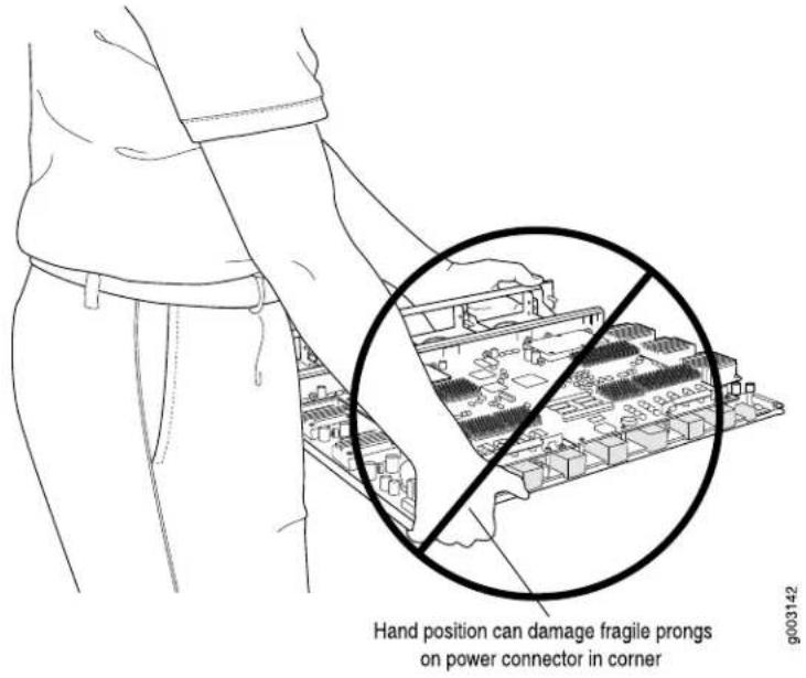
Figure 255: Do Not Carry an FPC with Only One Hand

natural_image
Line drawing of a person holding a device with a circular target overlay (no text or symbols)Figure 256: Do Not Rest the FPC on an Edge
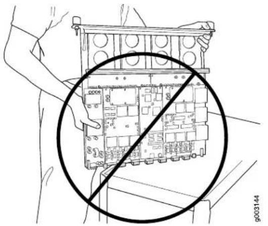
natural_image
Technical line drawing of a mechanical component with a circular annotation indicating no text or symbols (no readable text or symbols)Holding T1600 FPCs Vertically

NOTE: An FPC configured with PICs installed can weigh as much as 37 lb (14.5 kg). Be prepared to accept the full weight of the FPC as you lift it.
You hold an FPC vertically when installing it into the chassis. To hold an FPC vertically (see Figure 257 on page 484):
- Orient the FPC so that the faceplate faces you.
- Place one hand around the FPC faceplate about a quarter of the way down from the top edge. To avoid deforming the electromagnetic interference (EMI) shielding strip, do not press hard on it.
- Place your other hand at the bottom edge of the FPC. If the FPC has heat sinks about midway between the faceplate and connector edge, place your other hand against the heat sinks.
Figure 257: Holding an FPC Vertically

Holding T1600 FPCs Horizontally
To hold an FPC horizontally:
- Orient the FPC so that the faceplate is facing you.
- Grasp the top edge with your left hand and the bottom edge with your right hand.
You can rest the faceplate of the FPC against your body as you carry it (see Figure 258 on page 485.
Figure 258: Holding an FPC Horizontally

natural_image
Line drawing of a person handling an electronic circuit board (no text or symbols visible)Related Documentation
T1600 Flexible PIC Concentrator (FPC) Description on page 73.
•Replacing a T1600 FPC on page 377
•Storing T1600 FPCs on page 485
Storing T1600 FPCs
When an FPC is not installed in a router, the FPC must be either stored in the container in which a spare FPC is shipped or stored horizontally with the component-side up on a flat, stable surface. When you store an FPC on a horizontal surface or in the shipping container, always place it inside an antistatic bag. Because the FPC is heavy and because antistatic bags are fragile, inserting the FPC into the bag is easier with two people. The storage procedures are as follows:
- When storing an FPC with two people, one person holds the FPC in the horizontal position with the faceplate facing their body, the other person slides the opening of the bag over the FPC connector edge.
- When storing an FPC with one person, you must insert the FPC into a bag by yourself. First lay the FPC horizontally on a flat, stable surface, component-side up. Orient the FPC with the faceplate facing you. Carefully insert the FPC connector edge into the opening of the bag, and pull the bag toward you to cover the FPC.

CAUTION: To prevent damage when storing FPCs:
- Never lay an FPC component-side down.
Figure 259: Do Not Stack FPCs
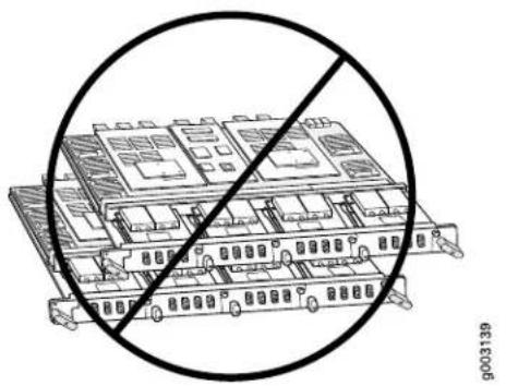
natural_image
Architectural line drawing of a multi-story building with a diagonal line crossing through it, no text or symbols present.- Never stack an FPC under or on top of any other component (see Figure 259 on page 486).
Related Documentation
T1600 Flexible PIC Concentrator (FPC) Description on page 73.
Maintaining the T1600 Host Subsystem
Each host subsystem comprises a Routing Engine and an adjacent control board functioning together.
To maintain the host subsystem, check the host subsystem LEDs (HOST0 and HOST1) on the craft interface. If the red HOST0 FAIL or HOST1 FAIL LED is lit, look at the LCD to get more information about the cause of the problem. For more information about the LEDs and the display, see "T1600 Craft Interface Description" on page 31
To maintain the Routing Engines and control boards:
- Maintaining the T1600 Routing Engines on page 486
- Maintaining the T1600 Control Boards on page 487
Maintaining the T1600 Routing Engines
Purpose For optimum router performance, verify the condition of the Routing Engines and the control boards.
Action On a regular basis:
- Check the LCD on the craft interface to view information about the router temperature and the status of the Routing Engines.
- Check the host subsystem LEDs on the craft interface. For more information about the LEDs and the display, see "T1600 Craft Interface Description" on page 31. During normal operations:
- The green host subsystem OK LED on the craft interface is lit.
- The red host subsystem FAIL LED on the craft interface is not lit.
- Check the LEDs on the RE-2000 faceplate. During normal operations, the ONLINE LED is lit steadilygreen.
- Check the LEDs on the RE-C1800 faceplate. During normal operations, the ONLINE LED is lit steadily green.
- Issue the show chassis routing-engine command to check the status of the Routing Engines. The output is similar to the following:
user@host> show chassis routing-engine
| Routing Engine status: | |||
| Slot 0: | |||
| Current state | Master | ||
| Election priority | Master (default) | ||
| Temperature | 34 degrees C / 93 degrees F | ||
| DRAM | 2048 Mbytes | ||
| CPU utilization: | |||
| User | 0 percent | ||
| Background | 0 percent | ||
| Kernel | 1 percent | ||
| Interrupt | 0 percent | ||
| Idle | 99 percent | ||
| Start time | 2002-01-22 05:21:31 UTC | ||
| Uptime | 10 days, 16 hours, 4 minutes, 52 seconds | ||
| Load averages: | 1 minute 5 minute 15 minute | ||
| 0.00 | 0.00 | 0.00 | |
| Routing Engine status: | |||
| Slot 1: | |||
| Current state | Empty | ||
For further description of the output from the commands, see show chassis routing-engine.
Maintaining the T1600 Control Boards
Purpose For optimum router performance, verify the condition of the control boards.
Action On a regular basis:
- Check the host subsystem LEDs on the craft interface. For more information about the LEDs and the display, see "T1600 Craft Interface Description" on page 31.
During normal operations:
- The green host subsystem OK LED on the craft interface is lit.
- The red host subsystem OK LED on the craft interface is not lit.
- Check the LEDs on the control board faceplate.
During normal operations:
•The green OK LED on the control board faceplate is lit.
- The yellow FAIL LED on the control board faceplate is not lit.
- Issue the show chassis environment cb command to check the status of the T-CBs. The output is similar to the following:
user@host> show chassis environment cb
| CB 0 status: | |
| State | Online Master |
| Temperature | 29 degrees C / 84 degrees F |
| Power: | |
| 1.8 V | 1809 mV |
| 2.5 V | 2496 mV |
| 3.3 V | 3295 mV |
| 4.6 V | 4687 mV |
| 5.0 V | 5042 mV |
| 12.0 V | 11985 mV |
| 3.3 V bias | 3277 mV |
| 8.0 V bias | 7472 mV |
| GBUS Revision | 40 |
| FPGA Revision | 7 |
For further description of the output from the commands, see show chassis environment cb.
Related T1600 Host Subsystem Description on page 41.
Documentation
•Troubleshooting the T1600 Host Subsystems on page 510
Maintaining T1600 PICs and PIC Cables
Purpose For optimum router performance, verify the condition of the PICs and PIC cables.
Action On a regular basis:
- Check the LEDs on PIC faceplates. A PIC LED lit green indicates the PIC is functioning normally. The meaning of the LED states differs for various PICs. For more information, see the interface module reference for your device. If the FPC that houses the PIC detects a PIC failure, the FPC generates an alarm message to be sent to the Routing Engine.
- Issue the CLI show chassis fpc pic-status command. The PIC slots in an FPC are numbered from 0 through 3, top to bottom:
user@host> show chassis fpc plc-status
| Slot 0 | Online | E-FPC Type 3 |
| PIC 0 | Online | 1x 10GE(LAN),DWDM |
| PIC 2 | Present | 1x OC-192 SONET XFP- Hardware Error |
| PIC 3 | Online | 1x 10GE(LAN),XENPAK |
| Slot 2 | Online | E2-FPC Type 2 |
| PIC 0 | Online | 1x OC-48 SONET, SMIR |
| PIC 1 | Online | 2x OC-12 ATM-II IQ, MM |
| PIC 2 | Online | 8x 1GE(LAN), IQ2 |
| Slot 3 | Online | FPC Type 3 |
| PIC 0 | Online | 1x 10GE(LAN),XENPAK |
| PIC 1 | Online | 1x 10GE(LAN),XENPAK |
| PIC 2 | Online | 8x 1GE(TYPE3), IQ2 |
| PIC 3 | Online | 8x 1GE(TYPE3), IQ2 |
| Slot 4 | Online | FPC Type 4 |
| PIC 0 Online | 4x OC-192 SONET XFP |
| Slot 6 Online | FPC Type 3 |
| PIC 0 Online | 4x OC-48 SONET |
| PIC 1 Online | 1x Tunnel |
| Slot 7 Online | FPC Type 4 |
| PIC 0 Online | 1x OC-768 SONET SR |
For further description of the output from the command, see show chassis fpc.
- Use the cable management system to support cables and prevent cables from dislodging or developing stress points.
- Place excess cable out of the way in the cable management system. Do not allow fastened loops of cable to dangle from the connector or cable management system, because this stresses the cable at the fastening point. Putting fasteners on the loops helps to maintain their shape.
- Keep the cable connections clean and free of dust and other particles, which can cause drops in the received power level. Always inspect cables and clean them if necessary before connecting an interface.
- Label both ends of PIC cables to identify them.
The following guidelines apply specifically to fiber-optic cable:
- When you unplug a fiber-optic cable from a PIC, always place a rubber safety plug over the transceiver on the PIC faceplate and on the end of the cable.
- Anchor fiber-optic cable to avoid stress on the connectors. When attaching fiber to a PIC, be sure to secure the fiber so it is not supporting its own weight as it hangs to the floor. Never let fiber-optic cable hang free from the connector.
- Avoid bending fiber-optic cable beyond its bend radius. An arc smaller than a few inches can damage the cable and cause problems that are difficult to diagnose.
- Frequent plugging and unplugging of fiber-optic cable into and out of optical instruments, such as ATM or SONET/SDH analyzers, can cause damage to the instruments that is expensive to repair. Instead, attach a short fiber extension to the optical equipment. Any wear and tear due to frequent plugging and unplugging is then absorbed by the short fiber extension, which is easy and inexpensive to replace.
- Keep fiber-optic cable connections clean. Small microdeposits of oil and dust in the canal of the transceiver or cable connector could cause loss of light, reducing signal power and possibly causing intermittent problems with the optical connection.
To clean the transceivers, use an appropriate fiber-cleaning device, such as RIFOCS Fiber Optic Adaptor Cleaning Wands (part number 946). Follow the directions for the cleaning kit you use.
After you have cleaned the transceiver on the fiber-optic PIC, make sure that the connector tip of the fiber-optic cable is clean. Use only an approved alcohol-free fiber-optic cable cleaning kit, such as the Optex CableCleaner. Follow the directions for the cleaning kit you use.
Related Documentation
T1600 Chassis Description on page 19.
- Connecting PIC Cables to the T1600 Router on page 236
•Replacing a T1600 PIC Cable on page 389
Maintaining the T1600 Power Supplies
Purpose For optimum router performance, verify the condition of the power supplies.
Action On a regular basis:
- Make sure that the power and grounding cables are arranged so that they do not obstruct access to other router components.
•The power supplies require an unobstructed airflow at both the front and rear of the chassis. Periodically check the site to ensure that both the air intake at the bottom front of the chassis and the exhaust from the power supply faceplates are unobstructed.
- Periodically inspect the site to ensure that the grounding and power cables connected to the router are securely in place and that no moisture accumulating near the router. To review grounding and site wiring requirements for the router, see "T1600 Chassis Grounding Cable and Lug Specifications" on page 132 and "Site Electrical Wiring Guidelines for Juniper Networks Devices" on page 584.
•Regularly inspect the air filters on each power supply for dust and debris, and replace the side filter on AC power supplies or front filter element on AC and DC power supplies every 6 months.
To replace a power supply air filter element, see the following topics:
•Replacing a Front Air Filter on a T1600 AC or Three-Input 240-A or Four-Input 240-A DC Power Supply on page 415
*Replacing a Side Air Filter on a T1600 AC Power Supply
•Replacing a T1600 Six-Input DC Power Supply Front Air Filter on page 423
•Replacing a T1600 Six-Input DC Power Supply Side Air Filter on page 424
•Routinely check the LEDs on the DC power supply faceplates.
During normal operation:
- For DC power supplies, the blue DC OK LEDs light to indicate that the power supplies are functioning normally.
- For DC power supplies, each green INPUT PRESENT LED on a DC power supply lights when the input is receiving source DC power.
- For three-input 240 -A power supplies and four-input 240 -A DC power supplies, each CB ON LED on a DC power supply lights when the circuit breaker is on.
- Routinely check the LEDs on the AC power supply faceplates. If the AC OK LEDs are lit, the AC terminal blocks are receiving power. If the DC OK LEDs are lit, the AC power supplies are functioning normally.
- Check the red and yellow alarm LEDs and the LCD on the craft interface. Power supply failure or removal triggers an alarm that causes one or both of the LEDs to light and an error message to appear on the LCD. You can display the associated error messages by issuing the following CLI command:
user@host> show chassis alarms
- Issue the show chassis environment pem command to check the status of the power supplies.
•For DC-powered routers with three-input 240-A DC power supplies or four-input 240-A DC power supplies, the output is similar to the following:
user@host> show chassis environment pem PEM 0 status:
| State | Online | |||
| Temperature | 41 degrees C / 105 degrees F | |||
| DC Input: | OK | |||
| DC Output | Voltage | Current | Power | Load |
| FPC 0 | 56775 | 1362 | 77 | 10 |
| FPC 1 | 57058 | 1318 | 75 | 10 |
| FPC 2 | 57483 | 1293 | 74 | 9 |
| FPC 3 | 57341 | 1318 | 75 | 10 |
| FPC 4 | 57100 | 1381 | 78 | 10 |
| FPC 5 | 57016 | 0 | 0 | 0 |
| FPC 6 | 57000 | 0 | 0 | 0 |
| FPC 7 | 56958 | 0 | 0 | 0 |
| SCG/CB/SIB | 56100 | 5975 | 335 | 27 |
PEM 1 status:
| State | Present | |||
| Temperature | 33 degrees C / 91 degrees F | |||
| DC Input: | Check | |||
| DC Output | Voltage | Current | Power | Load |
| FPC 0 | 0 | 0 | 0 | 0 |
| FPC 1 | 0 | 0 | 0 | 0 |
| FPC 2 | 0 | 0 | 0 | 0 |
| FPC 3 | 0 | 0 | 0 | 0 |
| FPC 4 | 0 | 0 | 0 | 0 |
| FPC 5 | 0 | 0 | 0 | 0 |
| FPC 6 | 0 | 0 | 0 | 0 |
| FPC 7 | 0 | 0 | 0 | 0 |
| SCG/CB/SIB | 0 | 0 | 0 | 0 |
If 0 is displayed for the SCG/CB/SIB in the Current, Power, and Load fields for a PEM, and the voltage field does not match the other PEM, it might indicate a difference between the DC input voltages applied to PEM0 and PEM1. Consider checking your DC power network for unintended voltage drops to the router (see Figure 59 on page 143 for a typical DC source cabling arrangement).
The current sharing between DC power supplies relies on equal voltages at the input terminals of the power supplies. However, if the voltages do not match, the router operates normally as long as the DC input voltages are within the operating range provided in Table 80 on page 137.
- For the three-input 240-A DC power supplies, system power is divided into two load zones. One load zone consists of INPUT 0 of PEMO and PEM1. The other load zones consist of INPUT 1 and INPUT 2 of PEMO and PEM1. Load sharing occurs between the two power supplies for each load zone. Therefore, the input voltage for the inputs in each load zone must be equal in both power supplies for current sharing. For example, the input voltage for INPUT 0 of PEMO and the input voltage for INPUT 0 of PEM1 must be the same for current sharing to occur within that load zone.
- For the four-input 240-A DC power supplies, system power is divided into four load zones. One load zone consists of INPUT 0 of PEM0 and PEM1. The other load zones consist of INPUT 1, INPUT 2 and INPUT 3 of PEM0 and PEM1. Load sharing occurs between the two power supplies for each load zone. Therefore, the input voltage for the inputs in each load zone must be equal in both power supplies for current sharing. For example, the input voltage for INPUT 0 of PEM0 and the input voltage for INPUT 0 of PEM1 must be the same for current sharing to occur within that load zone.
•For DC-powered routers with six-input DC power supplies, the output is similar to the following:
user@host> show chassis environment pem
| PEM 0 status: | ||||
| State | Online | |||
| Temperature | 34 degrees C / 93 degrees F | |||
| DC Input: | OK | |||
| Voltage(V) | Current(A) | Power(W) | Load(%) | |
| INPUT 0 | 53.500 | 7.437 | 397 | 52 |
| INPUT 1 | 53.750 | 10.812 | 581 | 77 |
| INPUT 2 | 53.125 | 9.562 | 507 | 67 |
| INPUT 3 | 53.625 | 11.125 | 596 | 79 |
| INPUT 4 | 53.750 | 9.875 | 530 | 70 |
| INPUT 5 | 53.250 | 9.500 | 505 | 67 |
| DC Output | Voltage(V) | Current(A) | Power(W) | Load(%) |
| FPC 0 | 0.000 | 0.000 | 0 | 0 |
| FPC 1 | 0.000 | 0.000 | 0 | 0 |
| FPC 2 | 0.000 | 0.000 | 0 | 0 |
| FPC 3 | 0.000 | 0.000 | 0 | 0 |
| FPC 4 | 55.375 | 9.562 | 529 | 70 |
| FPC 5 | 0.062 | 0.000 | 0 | 0 |
| FPC 6 | 55.062 | 9.000 | 495 | 66 |
| FPC 7 | 55.437 | 9.000 | 498 | 66 |
| SCG/CB/SIB | 55.375 | 15.375 | 851 | 70 |
| FAN | 49.000 | 7.875 | 385 | 51 |
For AC-powered routers, the output is similar to the following:
user@host> show chassis environment pem PEM 1 status:
| State | Online | |||
| Temperature | 33 degrees C / 91 degrees F | |||
| AC Input: | OK | |||
| DC Output | Voltage(mV) | Current(mA) | Power(W) | Load(%) |
| FPC 0 | 55183 | 7056 | 389 | 51 |
| FPC 1 | 55633 | 7018 | 390 | 52 |
| FPC 2 | 55533 | 5187 | 288 | 38 |
| FPC 3 | 55533 | 7081 | 393 | 52 |
| FPC 4 | 55508 | 6612 | 367 | 48 |
| FPC 5 | 55791 | 7337 | 409 | 54 |
| FPC 6 | 55675 | 2593 | 144 | 19 |
| FPC 7 | 55608 | 7600 | 422 | 56 |
| SCG/CB/SIB | 55308 | 5600 | 309 | 25 |
For further description of the output from the commands, see show chassis environment pem.
Related Documentation
T1600 Power System Description on page 105.
•T1600 General Electrical Safety Guidelines on page 575
•T1600 Preventing Electrostatic Discharge Damage on page 552
•Troubleshooting the T1600 Power System on page 516
•T1600 Alarm Messages Overview on page 506
Maintaining the T1600 Routing Engines
Purpose For optimum router performance, verify the condition of the Routing Engines and the control boards.
Action On a regular basis:
- Check the LCD on the craft interface to view information about the router temperature and the status of the Routing Engines.
- Check the host subsystem LEDs on the craft interface. For more information about the LEDs and the display, see "T1600 Craft Interface Description" on page 31. During normal operations:
- The green host subsystem OK LED on the craft interface is lit.
- The red host subsystem FAIL LED on the craft interface is not lit.
- Check the LEDs on the RE-2000 faceplate. During normal operations, the ONLINE LED is lit steadilygreen.
- Check the LEDs on the RE-C1800 faceplate. During normal operations, the ONLINE LED is lit steadily green.
- Issue the show chassis routing-engine command to check the status of the Routing Engines. The output is similar to the following:
user@host> show chassis routing-engine
Routing Engine status:
Slot 0:
Current state
Master
Election priority
Master (default)
Temperature
34 degrees C / 93 degrees F
DRAM
2048 Mbytes
CPU utilization:
User
Background
Kernel
Interrupt
Idle
Start time
Uptime
Load averages:
0 percent
0 percent
1 percent
0 percent
99 percent
2002-01-22 05:21:31 UTC
10 days, 16 hours, 4 minutes, 52 seconds
1 minute 5 minute 15 minute
0.00
0.00
0.00
Routing Engine status:
Slot 1:
Current state
Empty
For further description of the output from the commands, see show chassis routing-engine.
Related Documentation
T1600 Routing Engine Description on page 42.
•T1600 RE-600 LEDs on page 45
•T1600 RE-1600 LEDs on page 47
•T1600 RE-2000 LEDs on page 51
•T1600 RE-C1800 LEDs on page 49
•Troubleshooting the T1600 Host Subsystems on page 510
Maintaining the T1600 SCGs
Purpose For optimum router performance, verify the condition of the SCGs.
Action On a regular basis:
- Check the SCG LEDs. For more information, see "T1600 SCG LEDs" on page 30.
During normal operations:
•The green OK LED on the SCG faceplate is lit.
• The yellow FAIL LED on the SCG faceplate is not lit.
- Issue the show chassis environment scg command to display information about the SCGs. The output is similar to the following:
user@host> show chassis environment scg SCG 0 status:
| State | Online - Master clock |
| Temperature | 31 degrees C / 87 degrees F |
| Power: | |
| GROUND | 0 mV |
| 3.3 V | 3310 mV |
| 5.0 V | 5052 mV |
| 5.6 V | 5689 mV |
| 1.8 V bias | 1782 mV |
| 3.3 V bias | 3306 mV |
| 5.0 V bias | 4989 mV |
| 8.0 V bias | 8336 mV |
| GBUS Revision | 40 |
| FPGA Revision | 1.6 |
For further description of the output from the commands, see show chassis environment scg.
Related
Replacing a T1600 SCG on page 321.
Documentation
•Removing a T1600 SCG on page 321
Maintaining the T1600 SIBs
Purpose For optimum router performance, verify the condition of the SIBs.
Action On a regular basis:
- Observe the status of the SIBs by checking the LEDs on the SIB faceplate. During normal operations:
•The green OK LED on the SIB faceplate is lit. - The yellow FAIL LED on the SIB faceplate is not lit.
- To check the status of the SIBs using the CLI, issue the show chassis environment sib command. The output is similar to the following:
| user@host> show chassis environment sib | |
| SIB 0 status: | |
| State | Spare |
| Temperature | 45 degrees C / 113 degrees F |
| Power: | |
| GROUND | 0 mV |
| 1.8 V | 1794 mV |
| 2.5 V | 2446 mV |
| 3.3 V | 3291 mV |
| 1.8 V bias | 1780 mV |
| 3.3 V bias | 3284 mV |
| 5.0 V bias | 5003 mV |
| 8.0 V bias | 6910 mV |
| SIB 1 status: | |
| State | Online |
| Temperature | 45 degrees C / 113 degrees F |
| Power: | |
| GROUND | 0 mV |
| 1.8 V | 1802 mV |
| 2.5 V | 2461 mV |
| 3.3 V | 3294 mV |
| 1.8 V bias | 1782 mV |
| 3.3 V bias | 3294 mV |
| 5.0 V bias | 5013 mV |
| 8.0 V bias | 7057 mV |
| SIB 2 status: | |
| State | Online |
| Temperature | 47 degrees C / 116 degrees F |
| Power: | |
| GROUND | 0 mV |
| 1.8 V | 1794 mV |
| 2.5 V | 2461 mV |
| 3.3 V | 3301 mV |
| 1.8 V bias | 1785 mV |
| 3.3 V bias | 3296 mV |
| 5.0 V bias | 4998 mV |
| 8.0 V bias | 7050 mV |
For more information about using the command, see show chassis environment sib.
Related Documentation
T1600 Switch Interface Board (SIB) Description on page 119.
•T1600 Craft Interface SIB LEDs on page 35
•T1600-SIB LEDs on page 121
•Replacing a T1600-SIB on page 449
Cleaning Fiber-Optic Array Components with the Dry Cloth Cleaning Tool

NOTE: This procedure is required only for TX Matrix Plus components and T1600 routers in a routing matrix. It is not required for fiber-optic ports on the PICs.
As part of your routine maintenance, we recommend that you clean all exposed fiber-optic array components each time you disconnect and reconnect a fiber-optic array cable, or if the optical link is not functioning correctly.

NOTE: While you install the router or replace a fiber-optic array cable, small deposits of oil, dust, and debris can enter the fiber-optic array ports, the fiber-optic array cable connectors, and the loopback connectors and adapters used to test the optical connections. These deposits can cause loss of light, reducing signal power and causing intermittent problems with the optical connection.
The following tools for cleaning the fiber-optic components are provided in the TX Matrix Plus tool kit:
- Dry cleaning tool (see Figure 260 on page 497). This tool uses a dry cloth to remove dust and oil from the fiber optics.
- Cleaning tool adapter
- Cleaning tool connector
Figure 260: Cleaning Tool

To clean the fiber-optic components using the dry cloth cleaning tool:
-
Take the TX Matrix Plus switching plane offline. See the TX Matrix Plus Router Hardware Guide.
-
Bring the TXP-F13 SIB offline by pressing the SFC ONLINE/OFFLINE button.
-
Bring the TXP-T1600 SIB offline by pressing the ONLINE/OFFLINE button.
-
Disconnect the fiber-optic array cable between the TXP-F13 SIB and TXP-T1600 SIB.

WARNING: Do not look directly into a fiber-optic array port or a connector at the end of a fiber-optic array cable connected to a port. The fiber optics emit laser light that can damage your eyes.
- Attach an electrostatic discharge (ESD) grounding strap to your bare wrist, and connect the strap to one of the ESD points on the chassis.
-
Remove the dust cap from the fiber-optic array port. Open the dust shutter on the fiber-optic array port, and insert a cleaning adapter (see Figure 261 on page 498).
-
Remove the dust cap from the cleaning tool.
- Insert the tip of the dry cloth cleaning tool into the cleaning adapter (see Figure 261 on page 498).
Figure 261: Inserting the Cleaning Adapter into the Fiber-Optic Array Port and the Cleaning Tip into the Keyed Slot of the Cleaning Adapter
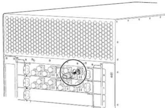
natural_image
Technical line drawing of a server rack with hexagonal panel and internal components (no text or symbols)Fiber-Optic Array Connector
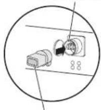
natural_image
Diagram of a connector with a 8.8Ω socket and cable, enclosed in a circle (no text or symbols)Cleaning tool adapter
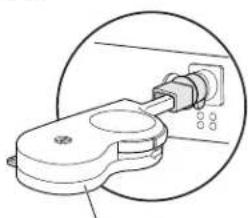
natural_image
Diagram of a mechanical component with a circular inset view showing a connector or assembly (no text or symbols)Cleaning tool
9004540

NOTE: This illustration shows TXP-F13 SIBs on a TX Matrix Plus router. However, the method for inserting the cleaning tool adapter and cleaning tool is the same for the TXP-T1600 SIB.

NOTE: The cleaning adapter is keyed to ensure that the cleaning tip can be inserted in only one way.
- Rotate the thumb wheel in the direction indicated on the cleaning tool until the thumb wheel clicks to indicate a completed cleaning action (see Figure 262 on page 499).
Figure 262: Rotating the Thumb Wheel

- Clean the three visible ferrules in the fiber-optic array port.
- Repeat these steps for all fiber-optic components that require cleaning.
- Remove the dust cap from the fiber-optic array cable. Insert a cleaning connector into the fiber-optic array cable (see Figure 263 on page 499). Insert the tip of the cleaning tool into the cleaning connector.
Figure 263: Inserting the Cleaning Connector into the Fiber-Optic Array Cable and the Cleaning Tip into the Keyed Slot of the Cleaning Connector
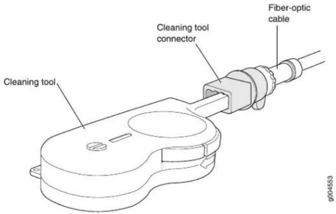
- Replace the dust cap on the cleaning tool.
- After you clean the fiber-optic array ports and the fiber-optic array cable connectors, reconnect the fiber-optic array cable between the TXP-F13 SIB fiber-optic array port and TXP-T1600 SIB fiber-optic array port.
- Bring the TXP-F13 SIB and TXP-1600 SIB online.
- Issue the show chassis slbs command. Verify that the TXP-F13 SIB and TXP-T1600 SIB are online.
- Issue the show chassis fabric plane extensive command. Verify that the state of each optical link is Links ok.
- If the state of any TXP-F13 SIB, TXP-T1600 SIB, or link is still incorrect, contact your customer support representative for additional instructions.
Related Documentation •T1600 Switch Interface Board (SIB) Description on page 119 •TXP-T1600 SIB Description on page 121
PART 6
Troubleshooting Hardware
- Troubleshooting Components on page 503
CHAPTER 34
Troubleshooting Components
• T1600 Troubleshooting Resources on page 503
• T1600 LED Overview on page 504
• T1600 Alarm Messages Overview on page 506
- Troubleshooting the T1600 Cooling System on page 507
- Troubleshooting the T1600 Craft Interface on page 510
- Troubleshooting the T1600 Host Subsystems on page 510
- Troubleshooting the T1600 Control Boards on page 511
- Troubleshooting the T1600 Cooling System on page 513
- Troubleshooting the T1600 FPCs on page 515
- Troubleshooting the T1600 Power System on page 516
- Troubleshooting the T1600 PICs on page 519
- Troubleshooting the T1600 SCGs on page 519
- Troubleshooting the T1600 SIBs on page 520
- Testing a Fiber-Optic Array Switching Plane Port on page 523
- Testing a Fiber-Optic Array Switching Plane Cable on page 524
T1600 Troubleshooting Resources
To troubleshoot a T1600 router, you use the Junos OS command-line interface (CLI), LCD, alarms, devices connected to the alarm relay contacts on the CIP, and LEDs on both the components and craft interface.
- LEDs—When the Routing Engine detects an alarm condition, it lights the red or yellow alarm LED on the craft interface as appropriate. In addition, you can also use the component-specific LEDs on the craft interface and on the faceplate of a component to troubleshoot the routing matrix.
- LCD—When a red or yellow alarm occurs, the cause of the alarm messages is displayed on the craft interface LCD. Use the CLI to display more information about the alarm.
- Alarm devices connected to the alarm relay contact on the CIP—When a red or yellow alarm occurs, it trips the corresponding alarm relay contact on the CIP.
- CLI—The CLI is the primary tool for controlling and troubleshooting hardware, Junos OS, routing protocols, and network connectivity. CLI commands display information from routing tables, information specific to routing protocols, and information about network connectivity derived from the ping and traceroute utilities.
For information about using the CLI to troubleshoot Junos OS, see the appropriate Junos OS configuration guide.
- JTAC—If you need assistance during troubleshooting, you can contact the Juniper Networks Technical Assistance Center (JTAC) by using the Web or by telephone. If you encounter software problems, or problems with hardware components not discussed here, contact JTAC.
Related Documentation
Contacting Customer Support on page 529.
• T1600 Connector Interface Panel (CIP) Description on page 25.
•T1600 Alarm Messages Overview on page 506
•T1600 Craft Interface Description on page 31
•T1600 LED Overview on page 504
T1600 LED Overview
• Craft Interface LED Overview on page 504
• Component LED Overview on page 505
Craft Interface LED Overview
The craft interface displays system status messages and allows you to troubleshoot the T1600 router. The craft interface is located on the upper front of the router. It contains LEDs, buttons, and an LCD display showing status messages for the router.
LEDs on the craft interface include the following:
- Alarm LEDs—One large red circular LED and one large yellow triangular LED, located on the upper left of the craft interface, indicate two levels of alarm conditions. You can determine the cause of the alarm condition by looking at the LCD on the craft interface.
See "T1600 Craft Interface Alarm LEDs and ACO/LT Button" on page 33.
- Host subsystem LEDs—Three LEDs (one green MASTER, one green OK, and one red FAIL) indicate the status of each host subsystem. The host subsystem LEDs are located on the upper right of the craft interface, and are labeled HOST0 and HOST1.
See "T1600 Craft Interface Host Subsystem LEDs" on page 34.
- SIB LEDs—Two LEDs (one red FAIL and one green OK) indicate the status of each SIB. The SIB LEDs are located on the upper right of the craft interface, and are labeled SIB0 through SIB4.
See "T1600 Craft Interface SIB LEDs" on page 35.
- FPC LEDs—Two LEDs (one red FAIL and one green OK) indicate the status of each FPC. The FPC LEDs are located along the bottom edge of the craft interface, and are labeled FPC0 through FPC7.
See "T1600 Craft Interface FPC LEDs" on page 35.
Component LED Overview
The following LEDs are located on various router components and display the status of those components:
- Connector interface panel (CIP) LEDs—Two small LEDs on the left edge of the ETHERNET port on the CIP indicate the connection in use.

NOTE: When RE-C1800 are installed, the LEDs are always yellow for both a 10-Mbps connection and 100-Mbps connection.
See "T1600 Connector Interface Panel (CIP) LEDs" on page 27.
- SIB LEDs—Three LEDs on each SIB faceplate—ACTIVE, OK, and FAIL—indicate the status of that SIB.
See "T1600-SIB LEDs" on page 121 and "TXP-T1600 SIB LEDs" on page 122.
- T-CB LEDs—Three LEDs on each T-CB faceplate—ACTIVE, OK, and FAIL—indicate the status of that T-CB. If no LEDs are lit, the T-CB is not receiving power.
See "T1600 T-CB LEDs" on page 68.
- LCC-CB LEDs—Three LEDs on each LCC-CB faceplate—ACTIVE, OK, and FAIL—indicate the status of that LCC-CB. The ACT and LINK LEDs indicate the status of each port. The JCS LINK port and LED are not currently supported. If no LEDs are lit, the LCC-CB is not receiving power.
See "T1600 LCC-CB LEDs" on page 70.
- SCG LEDs—Three LEDs on each SCG faceplate indicate the status of that SCG. If no LEDs are lit, the SCG is not receiving power.
See "T1600 SCG LEDs" on page 30.
- PIC LEDs—Each port on each PIC has an LED that indicates the status of the port.
See the T1600 Core Router Interface Module Reference.
- Power supply LEDs—LEDs on each power supply faceplate indicate the status of that power supply.
See "T1600 Three-Input 240-A DC Power Supply LEDs" on page 108, "T1600 Four-Input 240-A DC Power Supply LEDs" on page 111, "T1600 Six-Input DC Power Supply LEDs" on page 113, or "T1600 Three-Phase Delta and Wye AC Power Supply LEDs" on page 117.
T1600 Alarm Messages Overview
When the Routing Engine detects an alarm condition, it lights the red or yellow alarm LED on the craft interface as appropriate, trips the corresponding alarm relay contact on the CIP, and reports the cause of the alarm in the craft interface LCD. To view a more detailed description of the alarm cause, issue the show chassis alarms CLI command:
user@host> show chassis alarms
There are two classes of alarm messages:
- Chassis alarms indicate a problem with a chassis component such as the cooling system or power supplies.
Troubleshooting the T1600 SIBs on page 520
Troubleshooting the T1600 Host Subsystems on page 510
Troubleshooting the T1600 Control Boards on page 511
Troubleshooting the T1600 SCGs on page 519
Troubleshooting the T1600 Craft Interface on page 510
Troubleshooting the T1600 Cooling System on page 507
Troubleshooting the T1600 FPCs on page 515
Troubleshooting the T1600 PICs on page 519
Troubleshooting the T1600 Power System on page 516
- Interface alarms indicate a problem with a specific network interface, as described in Table 106 on page 506.
In Table 106 on page 506, the text in the column labeled "LCD Message" appears in the LCD. The text in the column labeled "CLI Message" appears in the output from the show chassis alarms command.
Table 106: SONET/SDH Interface Alarm Messages
| CLI MessageLCD Message | |
| interface-name so-x/x/x BERR-SD | interface-name so-x/x/x - SONET bit error rate defect |
| interface-name so-x/x/x BERR-SF | interface-name so-x/x/x - SONET bit error rate fault |
| interface-name so-x/x/x LAIS | interface-name so-x/x/x - SONET line AIS |
| interface-name so-x/x/x LOF | interface-name so-x/x/x - SONET loss of frame |
| interface-name so-x/x/x LOL | interface-name so-x/x/x - SONET loss of light |
| interface-name so-x/x/x LOP | interface-name so-x/x/x - SONET loss of pointer |
| interface-name so-x/x/x LOS | interface-name so-x/x/x - SONET loss of signal |
| interface-name so-x/x/x LRDI | interface-name so-x/x/x - SONET line remote defect indicator |
| interface-name so-x/x/x PAIS | interface-name so-x/x/x - SONET path AIS |
| interface-name so-x/x/x PLL | interface-name so-x/x/x - SONET PLL lock |
| interface-name so-x/x/x PMIS | interface-name so-x/x/x - SONET path mismatch |
| interface-name so-x/x/x PRDI | interface-name so-x/x/x - SONET path remote defect indicator |
| interface-name so-x/x/x REI | interface-name so-x/x/x - SONET remote error indicator |
| interface-name so-x/x/x SEF | interface-name so-x/x/x - SONET severely errored frame |
| interface-name so-x/x/x UNEQ | interface-name so-x/x/x - SONET unequipped |
Related Documentation
Overview of Connecting the T1600 Router to External Devices on page 231.
•Routine Maintenance Procedures for the T1600 Router on page 473
•T1600 Chassis Description on page 19
Troubleshooting the T1600 Cooling System
Problem Description:
The following alarms, LEDs, and other conditions indicate a problem with the cooling system:
•A red alarm indicates that temperature of the router exceeds the maximum ("temperature hot") threshold.
- Automatic shutdown of the power supplies was caused by the temperature of the router exceeding the maximum ("temperature hot") threshold. The control board turns off the power supplies because the router temperature exceeds the acceptable maximum.
•A red alarm indicates that a fan failed.
- A yellow alarm indicates that the router temperature exceeds the "temperature warm" threshold.
• A yellow alarm indicates that one of the fan trays was removed.
- One or more fans in a fan tray function at full speed. The control boards constantly monitor the temperatures detected by sensors on the midplane and router components, adjusting the speed of the fans as necessary.
In Table 107 on page 508, the text in the column labeled "LCD Message" appears in the display of the craft interface. The text in the column labeled "CLI Message" appears in the output from the show chassis alarms command.
Table 107: T1600 Cooling System Alarms
| Alarm TypeComponent | SolutionAlarm Con | ||||
| Fans | Red | Fan Failure | fan-name Failure | A fan has failed. | Replace the fan tray. |
| Fans Missing | Too many fans missing or failing | A fan tray is missingReinstall the fan tray or too many fan trays in the chassis.have failed. | |||
| T1600 Rear Fan Tray LCC | in1600 Rear Fan Tray in LCC | For T1600 routers in Replace the rear fan a routing matrix, the tray with part number rear fan tray part number 760-024613.is not supported. | |||
| Yellow | Fan Removed | fan-name Removed | A fan tray has been removed. | Reinstall the fan tray in the chassis. | |
| Mix of FAN-TRAYS | Minor - Mix of FAN-TRAYS | A mix of standard front fan trays and quiet front fan trays are installed in the chassis. | Check that all fan trays are either standard fan trays or quiet fan trays.Install the correct fan trays. | ||
| NOTE: During normal operations,mixing the standard and quiet fan trays is not supported. | NOTE: During an upgrade, ignore this alarm. | ||||
Table 107: T1600 Cooling System Alarms (continued)
| AlarmTypeComponent | SolutionAlarm Con | ||||
| sensors | Temperature Hot Temperature Hot Red Temperature Exceeded the hot temperature threshold. If this condition persists, the router shuts down. | Verify that the room temperature is within acceptable limits.Verify that there is sufficient air flow.Verify that the cooling system in the chassis is operating properly. | |||
| Sensor Failure | Temperature sensor failure | failed. | Contact JTAC.A temperature sensor | ||
| Yellow | Temperature Warm | Temperature Warm | The chassis temperature exceeded the warm temperature threshold. | Verify that the room temperature is within acceptable limits.Verify that there is sufficient air flow.Verify that the cooling system in the chassis is operating properly. |
Solution To troubleshoot the cooling system:
- Place your hand near the exhaust vents at the rear of the chassis to determine whether the fans are pushing air out of the chassis.
- If the red alarm LED on the craft interface lights, look at the craft interface display to find the source of the problem. The number of alarm conditions, as well as the source of each alarm, appears on the screen.
- If the craft interface display lists only one fan failure and the other fans are functioning normally, the fan is probably faulty and you need to replace the fan tray.
- Use the CLI to check the status of the fans. For example, you can issue the following command to get information about the source of an alarm condition:
user@host> show chassis alarms
For information about the alarms, see Table 107 on page 508.
Related T1600 Cooling System Description on page 37
Documentation
•T1600 Chassis Description on page 19
•Replacing the T1600 Standard Lower Front Fan Tray on page 325
•Replacing the T1600 Standard Upper Front Fan Tray on page 326
•Replacing the T1600 Rear Fan Tray on page 328
•Replacing the T1600 Rear Air Filter on page 307
•Replacing the T1600 Front Air Filter on page 305
Troubleshooting the T1600 Craft Interface
Problem Description:
The following alarms, LEDs, and other conditions indicate a problem with the craft interface:
•The router is powered on, but none of the LEDs on the craft interface are lit.
•A yellow alarm indicates that the craft interface has failed.
In Table 108 on page 510, the text in the column labeled "LCD Message" appears in the display of the craft interface. The text in the column labeled "CLI Message" appears in the output from the show chassis alarms command.
Table 108: T1600 Chassis Alarm Messages for the Craft Interface
| CLI MessageLCD MessageAla |
Craft FailureCraft FailureYellow
Solution To troubleshoot the T1600 craft interface:
- Check the LEDs on the craft interface.
- Use the CLI to check for alarms.
- Standalone T1600 router—Issue the show chassis alarms command to view the alarms.
- T1600 router in a routing matrix—Issue the show chassis alarms lcc lcc-number command to view the alarms.
Related Documentation
T1600 Craft Interface Description on page 31.
•T1600 Craft Interface Alarm LEDs and ACO/LT Button on page 33
Troubleshooting the T1600 Host Subsystems
Problem Description:
The following alarms and LEDs indicate a problem with a host subsystem control board and Routing Engine:
• A red alarm indicates that the host subsystem has been removed.
• A yellow alarm indicates that the host subsystem has failed.
- The red host subsystem FAIL LED on the craft interface is lit.
- The green host subsystem OK LED on the craft interface is not lit.
In Table 109 on page 511, the text in the column labeled "LCD Message" appears in the display of the craft interface. The text in the column labeled "CLI Message" appears in the output from the show chassis alarms command.
Table 109: T1600 Chassis Alarm Messages for Host Subsystems
| CLI MessageLCD MessageA | ||
| Red | Host host-number Removed | Host host-number Removed |
| Yellow | Host host-number Failure | Host host-number Failure |
Solution To troubleshoot the host subsystems:
- Check the LEDs on the faceplate of each control board and Routing Engine.
- Check the LEDs on the craft interface.
- Use the CLI to check for alarms.
- Standalone T1600 router—Issue the show chassis alarms command to view the alarms.
- T1600 router in a routing matrix—Issue the show chassis alarms lcc lcc-number command to view the alarms.
Related T1600 Host Subsystem Description on page 41. Documentation T1600 Routing Engine Description on page 42.
•T1600 Routing Engine Description on page 42
•T1600 Control Boards Description on page 66
•T1600 Craft Interface Host Subsystem LEDs on page 34
•T1600 RE-600 LEDs on page 45
•T1600 RE-1600 LEDs on page 47
•T1600 RE-C1800 LEDs on page 49
•T1600 RE-2000 LEDs on page 51
•T1600 T-CB LEDs on page 68
Troubleshooting the T1600 Control Boards
Problem Description:
The following alarms and LEDs indicate a problem with a control board:
• A red alarm indicates that the control board has failed or has been removed.
• A yellow alarm indicates that the Ethernet switch in the control board has failed.
- The yellow FAIL LED on the control board faceplate is lit.
•The green OK LED on the control board faceplate is not lit.
- The red host subsystem FAIL LED on the craft interface is lit.
- The green host subsystem OK LED on the craft interface is not lit.
In Table 110 on page 512, the text in the column labeled "LCD Message" appears in the display of the craft interface. The text in the column labeled "CLI Message" appears in the output from the show chassis alarms command.
Table 110: T1600 Chassis Alarm Messages for the Control Boards
| CLI MessageLCD MessageAI | ||
| Red | CB cb-number Removed | CB cb-number Removed |
| CB cb-number FailureCB cb-number Failure | ||
| CB cb-number Ethernet Switch Failure | CB cb-number Ethernet Switch Failure |
Solution To troubleshoot the T1600 control boards:
- Check the LEDs on the faceplate of each control board.
- Check the LEDs on the craft interface.
- Use the CLI to check for alarms.
- Standalone T1600 router—Issue the show chassis alarms command to view the alarms.
- T1600 router in a routing matrix—Issue the show chassis alarms lcc lcc-number command to view the alarms.
Related Documentation
T1600 Host Subsystem Description on page 41.
•T1600 Control Boards Description on page 66
•T1600 Craft Interface Host Subsystem LEDs on page 34
•T1600 LCC-CB LEDs on page 70
•T1600 T-CB LEDs on page 68
Troubleshooting the T1600 Cooling System
Problem Description:
The following alarms, LEDs, and other conditions indicate a problem with the cooling system:
- A red alarm indicates that temperature of the router exceeds the maximum ("temperature hot") threshold.
- Automatic shutdown of the power supplies was caused by the temperature of the router exceeding the maximum ("temperature hot") threshold. The control board turns off the power supplies because the router temperature exceeds the acceptable maximum.
•A red alarm indicates that a fan failed. - A yellow alarm indicates that the router temperature exceeds the "temperature warm" threshold.
• A yellow alarm indicates that one of the fan trays was removed.
•One or more fans in a fan tray function at full speed. The control boards constantly monitor the temperatures detected by sensors on the midplane and router components, adjusting the speed of the fans as necessary.
In Table 107 on page 508, the text in the column labeled "LCD Message" appears in the display of the craft interface. The text in the column labeled "CLI Message" appears in the output from the show chassis alarms command.
Table 111: T1600 Cooling System Alarms
| Alarm TypeComponent | SolutionAlarm Cond | ||||
| Fans | Red | Fan Failure | fan-name Failure | A fan has failed. | Replace the fan tray. |
| Fans Missing | Too many fans missing or failing | A fan tray is missingReinstall the fan tray or too many fan trays in the chassis.have failed. | |||
| T1600 Rear Fan Tray in LCC | T1600 Rear Fan Tray In LCC | For T1600 routers in Replace the rear fan a routing matrix, the tray with part number rear fan tray part number 760-009870is not supported. | |||
| Yellow | Fan Removed | fan-name Removed | A fan tray has been removed. | Reinstall the fan tray in the chassis. | |
| Mix of FAN-TRAYS | Minor-Mix of FAN-TRAYS | A mix of standard front fan trays and quiet front fan trays are installed in the chassis.NOTE: During normal operations,mixing the standard and quiet fan trays is not supported. | Check that all fan trays are either standard fan trays or quiet fan trays. Install the correct fan trays.NOTE: During an upgrade, ignore this alarm. | ||
| Temperature sensors | Red | Temperature Hot | Temperature Hot | The chassis temperature exceeded the hot temperature threshold. If this condition persists,the router shuts down. | Verify that the room temperature is within acceptable limits.Verify that there is sufficient air flow.Verify that the cooling system in the chassis is operating properly. |
| Sensor Failure | Temperature sensor failure | A temperature sensor failed. | Contact JTAC. | ||
| Yellow | Temperature Warm | Temperature Warm | The chassis temperature exceeded the warm temperature threshold. | Verify that the room temperature is within acceptable limits.Verify that there is sufficient air flow.Verify that the cooling system in the chassis is operating properly. | |
Solution To troubleshoot the cooling system:
- Place your hand near the exhaust vents at the rear of the chassis to determine whether the fans are pushing air out of the chassis.
- If the red alarm LED on the craft interface lights, look at the craft interface display to find the source of the problem. The number of alarm conditions, as well as the source of each alarm, appears on the screen.
- If the craft interface display lists only one fan failure and the other fans are functioning normally, the fan is probably faulty and you need to replace the fan tray.
- Use the CLI to check the status of the fans. For example, you can issue the following command to get information about the source of an alarm condition:
user@host> show chassis alarms
For information about the alarms, see Table 107 on page 508.
Related Documentation T1600 Cooling System Description on page 37.
•T1600 Chassis Description on page 19
•Replacing the T1600 Standard Lower Front Fan Tray on page 325
•Replacing the T1600 Standard Upper Front Fan Tray on page 326
•Replacing the T1600 Rear Fan Tray on page 328
•Replacing the T1600 Rear Air Filter on page 307
•Replacing the T1600 Front Air Filter on page 305
Troubleshooting the T1600 FPCs
Problem Description:
The following LEDs indicate a problem with an FPC:
• The red FAIL LED above the FPC is lit.
•The green OK LED above the FPC is not lit.
Solution To troubleshoot an FPC:
- Look at the display on the craft interface to check the status of the FPC and the PICs that are plugged into it.
- Verify that the FPC is properly seated in the midplane. Check that each ejector handle has been turned clockwise and is tight. Use a screwdriver to check that the screws inside the ejector handles are tight.
- Check the status of an FPC using the following CLI command:
user@host> show chassis fpc - Use the following option to display more detailed information:
user@host> show chassis fpc detail
| Related Documentation | T1600 Flexible PIC Concentrator (FPC) Description on page 73. |
| •T1600 Craft Interface FPC LEDs on page 35 | |
| •Maintaining T1600 FPCs on page 480 | |
| •Replacing a T1600 FPC on page 377 |
Troubleshooting the T1600 Power System
Problem Description:
The following alarms, LEDs, and other conditions indicate a problem with the power system:
- If all power supplies have failed, the system temperature might have exceeded the threshold, causing the system to shut down.
- The blue DC OK LED blinks when a power supply detects a fault (the power supply fails, does not have sufficient airflow, is going through a startup test, or is not properly inserted).
- The yellow OVER TEMP LED lights when a power supply is not receiving enough airflow to maintain proper temperature.
- The green AC OK LED is off when an AC power supply is not receiving voltage.
In Table 112 on page 516, the text in the column labeled "LCD Message" appears in the display of the craft interface. The text in the column labeled "CLI Message" appears in the output from the show chassis alarms command.
Table 112: Power System Chassis Alarms
| CLI MessageLCD MessageAlarm | ||
| Red | PEM pem-number Over Temp | PEM pem-number Over Temperature |
| PEM pem-number Output FailurePEM pem-number Output Fail | ||
| PEM pem-number Input FailurePEM pem-number Input Fail | ||
| Yellow | PEM pem-number Removed | PEM pem-number Removed |
| PEM pem-number Inputs Cfg | PEM pem-number ConfigurationMismatch-number of inputs |
Solution 1. Check the LEDs on each three-input 240-A DC or four-input 240-A DC power supply faceplate.
- DC OK power supply LED is blinking—Check the red alarm LED on the craft interface.
- DC OK power supply LED is off and no red alarm condition exists—Check that the circuit breakers are switched to the ON position (I).
-
DC OK LED on one or both of the power supplies is not lit—Check the power supply fans to see if they are operating.
• OVERTEMP LED on one of the power supplies lights—Check the fans and air filters to be sure they are functioning and providing sufficient airflow through the chassis. -
Check the LEDs on each six-input DC power supply faceplate.
-
The DC OK LED on one or both of the power supplies is not lit—Check that the power switch is on.
- The OVER TEMP LED on one of the power supplies is lit—Check the fan trays and air filters to be sure they are functioning and providing sufficient airflow through the chassis.
-
An INPUT PRESENT LED on a DC power supply is not lit—Check that the input is receiving source DC power.
-
Check the LEDs on each three-phase delta or wye power supply faceplate.
-
AC OK power supply LED is off—Check that the power supply is receiving voltage.
- DC OK power supply LED is blinking—Check the red alarm LED on the craft interface.
-
DC OK LED on one or both of the power supplies is not lit—Check the power supply fans to see if they are operating.
• OVERTEMP LED on one of the power supplies lights—Check the fans and air filters to be sure they are functioning and providing sufficient airflow through the chassis. -
Check the display on the craft interface to determine the source of a yellow or red alarm (see Table 112 on page 516). Junos OS constantly updates the screen with status information for each component.

NOTE: On the display and in the CLI, the power supplies are referred to as PEMO and PEMO, from top to bottom.
If the system temperature exceeds the threshold, Junos OS shuts down all power supplies so that no status is displayed.
Junos OS also can shut down one of the power supplies for other reasons. In that case, the remaining power supply assumes the load, and you can still view the system status through the CLI or display.
- Verify that the source circuit breaker has the proper current rating.

NOTE: All inputs on a DC power supply in slot PEM0 must be powered by dedicated power feeds derived from feed A, and all inputs on a DC power supply in slot PEM 1 must be powered by dedicated power feeds derived from feed B. This configuration provides the commonly deployed A/B feed redundancy for the system.

NOTE: The AC power cord on an AC power supply in slot PEM0 must be powered by a dedicated power feed derived from feed A, and The AC power cord on an AC power supply in slot PEM 1 must be powered by dedicated power feeds derived from feed B. This configuration provides the commonly deployed A/B feed redundancy for the system.
- Verify that the DC power cables or AC power cord from the power source to the router are not damaged. If the insulation is cracked or broken, immediately replace the DC power cable or AC power cord.
- Connect the power supply to a different power source with a new DC power cable or AC power cord. If the power supply DC OK LED still does not light, the power supply is the source of the problem. Replace the power supply with a spare.
DC OK LED on the installed spare does not light—the replaced power supply might be faulty. To return it for replacement, see "Contacting Customer Support" on page 529. - If you cannot determine the cause of the problem or need additional assistance, see "Contacting Customer Support" on page 529.
Related Documentation
T1600 Craft Interface Description on page 31.
•Replacing a T1600 Three-Input 240-A DC Power Supply on page 394
•Replacing a T1600 Four-Input 240-A DC Power Supply on page 403
•Replacing a T1600 DC Power Supply Cable on a Three-Input 240-A DC Power Supply or Four-Input 240-A DC Power Supply on page 409
•Replacing a T1600 Six-Input DC Power Supply on page 417
- Replacing a T1600 DC Power Supply Cable on a Six-Input DC Power Supply on page 421
•Replacing a T1600 Three-Phase Delta AC Power Supply on page 426
•Replacing a T1600 Three-Phase Delta AC Power Supply Cord on page 433
•Replacing a T1600 Three-Phase Wye AC Power Supply on page 438
•Replacing a T1600 Three-Phase Wye AC Power Supply Cord on page 444
Troubleshooting the T1600 PICs
Problem Description: A PIC LED lit red indicates a problem with the PIC.
Solution To troubleshoot a PIC:
-
Check the status of each port on a PIC. Look at the LEDs located on the PIC faceplate. For information about the meaning of LED states on different PICs, see the T7600 Core Router Interface Module Reference.
-
Check the status of a PIC, issuing the following CLI command. The PIC slots in the FPC are numbered from 0 through 3, top to bottom:
user@host> show chassis fpc pic-status
| Slot 0 | Online | E-FPC Type 3 |
| PIC 0 | Online | 1x 10GE(LAN),DWDM |
| PIC 2 | Present | 1x OC-192 SONET XFP- Hardware Error |
| PIC 3 | Online | 1x 10GE(LAN),XENPAK |
| Slot 2 | Online | E2-FPC Type 2 |
| PIC 0 | Online | 1x OC-48 SONET, SMIR |
| PIC 1 | Online | 2x OC-12 ATM-II IQ, MM |
| PIC 2 | Online | 8x 1GE(LAN), IQ2 |
| Slot 3 | Online | FPC Type 3 |
| PIC 0 | Online | 1x 10GE(LAN),XENPAK |
| PIC 1 | Online | 1x 10GE(LAN),XENPAK |
| PIC 2 | Online | 8x 1GE(TYPE3), IQ2 |
| PIC 3 | Online | 8x 1GE(TYPE3), IQ2 |
| Slot 4 | Online | FPC Type 4 |
| PIC 0 | Online | 4x OC-192 SONET XFP |
| Slot 6 | Online | FPC Type 3 |
| PIC 0 | Online | 4x OC-48 SONET |
| PIC 1 | Online | 1x Tunnel |
| Slot 7 | Online | FPC Type 4 |
| PIC 0 | Online | 1x OC-768 SONET SR |
For further description of the output from the command, see show chassis fpc.
Related T1600 PIC Description on page 86.
Documentation
- Maintaining T1600 PICs and PIC Cables on page 488
Troubleshooting the T1600 SCGs
Problem Description:
The following alarms and LEDs indicate a problem with an SCG:
• A red alarm indicates that the SCG has failed or has been removed.
•A yellow alarm indicates that the SCG is not online.
- The yellow FAIL LED on the SCG faceplate is lit.
•The green OK LED on the SCG faceplate is not lit.
In Table 113 on page 520, the text in the column labeled "LCD Message" appears in the display of the craft interface. The text in the column labeled "CLI Message" appears in the output from the show chassis alarms command.
Table 113: Chassis Alarm Messages for the SCGs
| CLI MessageLCD MessageAlarm Type | ||
| Red | SCG SCG-numberFailure | SCG SCG-number Failure |
| SCG SCG-numberRemoved | SCG SCG-number Removed | |
| Yellow | SCG SCG-number NotOnline | SCG SCG-number Not Online |
Solution To troubleshoot the T1600 SCGs:
- Check the LEDs on the faceplate of each SCG.
- Check the LEDs on the craft interface.
-
Use the CLI to check for alarms.
-
Standalone T1600 router—Issue the show chassis alarms command to view the alarms.
- T1600 router in a routing matrix—Issue the show chassis alarms lcc lcc-number command to view the alarms.
Related Documentation
T1600 SONET Clock Generators Description on page 28
•T1600 SCG LEDs on page 30
Troubleshooting the T1600 SIBs
Problem Description:
The following alarms and LEDs indicate a problem with a SIB:
• A red alarm indicates that the SIB failed or has been removed.
• A yellow alarm indicates that a spare SIB has failed or has been removed.
- The yellow FAIL LED on the SIB faceplate is lit.
•The green OK LED on the SIB faceplate is not lit.
In Table 114 on page 521 and Table 115 on page 521, the text in the column labeled "LCD Message" appears in the display of the craft interface. The text in the column labeled "CLI Message" appears in the output from the show chassis alarms command.
Table 114: T1600 Chassis Alarm Messages for SIBs
| SolutionAlarm ConditionCLI N | ||||
| Red | SIB sib-number Failure | SIB sib-number Fault | switching plane has failed. | Replace the SIB.A SIB on an active |
| Removed | SIB sib-number Absent | SIB sib-number switching plane has been removed. | Reinstall the SIB in the chassis.A SIB on an a | |
| Yellow | Spare SIB Failure | Spare SIB Fault | A SIB on a backup switching plane has failed. | Replace the SIB. |
| Spare SIB Removed | Spare SIB Absent | switching plane has been removed. | Reinstall the SIB in the chassis.A SIB on a ba | |
| Check SIB | Check SIB | SIB is not inserted properly,destination errors are detected on the SIB, or link errors are detected on the channel between the SIB and a Packet Forwarding Engine in an FPC. | Check that the SIB is correctly installed.For destination errors,use the showchassis fabric fpcs commandand showchassis fabric sibs command for more details. |
Solution To troubleshoot the T1600 SIBs:
- Check the LEDs on the faceplate of each SIB.
- Check the LEDs on the craft interface.
-
Use the CLI to check for alarms.
-
Standalone T1600 router—Issue the show chassis alarms command to view the alarms.
- T1600 router in a routing matrix—Issue the show chassis alarms lcc lcc-number command to view the alarms.
Table 115: Chassis Alarm Messages for a T1600 Router in a Routing Matrix
| Alarm Type | Craft Interface LCD Message | CLI Message | Alarm Condition | Solution |
| Red | ST_SIB_Lsib-number:VCSEL Fault | ST_SIB_Lsib-number. SIB VCSEL Fault | Loss of signal (LOS) has occurred in a vertical-cavity surface-emitting laser (VCSEL) in a TXP-T1600 SIB. | Replace the TXP-T1600 SIB on the T1600 router. |
| Craft InterfaceLCD MessageAlarm Type | SolutionAlarmCondI | |||
| SIB sib-numberFPC Links | SIB sib-numberFPC Link Error | The TXP-T1600 SIB has detected Link errors on FPC-SIB links. | To isolate the problem:1. Replace the TXP-T1600 SIB.2. If the problem persists, replace each FPC.3. If you are unable to isolate the problem, contact JTAC. | |
Related Documentation
T1600 Craft Interface SIB LEDs on page 35.
•T1600-SIB Description on page 120
•TXP-T1600 SIB Description on page 121
•T1600-SIB LEDs on page 121
•TXP-T1600 SIB LEDs on page 122
•Replacing a T1600-SIB on page 449
•Replacing a TXP-T1600 SIB on page 452
Testing a Fiber-Optic Array Switching Plane Port
Four fiber-optic array loopback connectors are shipped in the tool kit with the TX Matrix Plus router (see Figure 264 on page 523).

NOTE: Use the loopback connectors to test the TXP-F13 ports.
Figure 264: TX Matrix Plus Fiber-Optic Array Switching Plane Loopback Connector and Loopback Adapter


CAUTION: Do not connect and disconnect the fiber-optic array switching plane cable connectors, loopback connectors, or loopback adapters more frequently than required to perform the procedures in this hardware guide. These fiber-optic components are rated for a limited number of insertions (approximately 100).
To use the loopback connectors to test the TXP-F13 SIB fiber-optic array switching plane ports:
- Attach an electrostatic discharge (ESD) grounding strap to your bare wrist, and connect the strap to one of the ESD points on the chassis.
- Take the switching plane offline.
See Taking a Switching Data Plane Offline in the TX Matrix Plus Router Hardware Guide. - Bring the TXP-F13 SIB offline by pressing the SFC ONLINE/OFFLINE button.
- Remove the dust covers from the loopback connectors and from the fiber-optic array switching plane ports. Temporarily store the dust covers in a dust-free resealable plastic bag.

CAUTION: During maintenanceor replacementprocedures,small deposits of oil, dust, and debris can enter the TXP-F13 SIB and TXP-T1600 SIB
fiber-optic array switching plane ports, the fiber-optic array switching plane cable connectors, and the loopback connectors and adapters.
- Align a loopback connector with each TXP-F13 SIB fiber-optic array switching plane port, and carefully press it into the port until it stops. The loopback connector and fiber-optic array switching plane port are keyed to ensure proper mating.
- Bring the TXP-F13 SIB online by pressing the SFC ONLINE/OFFLINE button.
- Verify that the RxPWR LED for that fiber-optic array switching plane port is steadily lit green.
- If the RxPWR LED for any fiber-optic array switching plane port is lit steadily yellow or is not lit, take the TXP-F13 SIB offline again, remove the loopback connector, and clean the fiber-optic array switching plane ports and loopback connectors. Then reconnect the loopback connectors.
If the RxPWR LEDs for the fiber-optic array switching plane ports still fail to light steadily green, contact your customer support representative for additional instructions. - After you have finished testing the fiber-optic array switching plane port, remove a dust cover from the dust-free resealable plastic bag. To reinstall the dust cover on the loopback connector, align the dust cover with the loopback connector, and carefully press them together until they stop. The covers and the loopback connectors are keyed to ensure proper mating. Store the loopback connectors in the dust-free resealable plastic bag.
Related Documentation
Troubleshooting Switching Plane Connections to TX Matrix Plus TXP-F13 SIBs.
•T1600 Preventing Electrostatic Discharge Damage on page 552
•Cleaning Fiber-Optic Array Components with the Dry Cloth Cleaning Tool on page 496
Testing a Fiber-Optic Array Switching Plane Cable
Use a fiber-optic array loopback adapter (see Figure 265 on page 526) that is shipped in the TX Matrix Plus tool kit to test the integrity of the fiber-optic array cables.
To test a fiber-optic array cable:
- Attach an electrostatic discharge (ESD) grounding strap to your bare wrist, and connect the strap to one of the ESD points on the chassis.
- Remove the dust cover from the loopback adapter and the fiber-optic array cable. Store the dust covers in a dust-free resealable plastic bag.
- Take the switching plane offline.
See Taking a Switching Data Plane Offline in the TX Matrix Plus Router Hardware Guide. - Bring the TXP-F13 SIB offline by pressing the ONLINE/OFFLINE button for the SFC.

WARNING: Do not look directly into a fiber-optic array switching plane port or a connector at the end of a fiber-optic array switching plane cable connected toaport.Theopticsemitlaser light thatcan damage youreyes.
-
Disconnect the fiber-optic array switching plane cable from the port.
-
Install a dust cover on the fiber-optic array switching plane port.
-
Clean the fiber-optic array switching plane cable and loopback adapter.

CAUTION: During maintenanceorreplacement procedures, small deposits of oil, dust, and debris can enter the TXP-F13 SIB and TXP-T1600 SIB fiber-optic array switching plane ports, fiber-optic array switching plane cable connectors, and loopbackconnectorsandadapters. We recommend that you clean the optics in these components immediately before connecting them.
-
Align the loopback adapter with the cable connector, and carefully press it into the connector until it stops. The loopback adapter and the cable connector are keyed to ensure proper mating.
-
Bring the TXP-F13 SIB online by pressing the ONLINE/OFFLINE button for the SFC.

WARNING: Do not look directly into a fiber-optic array switching plane port or a connector at the end of a fiber-optic array switching plane cable connected to a port. The fiber optics emit laser light that can damage your eyes.
-
Verify that the RxPWR LED for the fiber-optic array switching plane port is steadily lit green.
-
If the RxPWR LED for a fiber-optic array switching plane port is lit steadily yellow or is not lit, bring the TXP-F13 SIB offline, remove the loopback adapter, and clean it and the fiber-optic array cable. After you have cleaned the fiber-optic array switching plane cable and the loopback adapter, repeat the procedure. If the RxPWR LED for a fiber-optic array switching plane port still does not steadily light green, contact your customer support representative for additional instructions. Do not proceed with the installation of the TX Matrix Plus router until you have spoken to your customer support representative.
-
Remove a dust cover from the dust-free resealable plastic bag and reinstall it on the loopback adapter. Align the dust cover with the loopback adapter, and carefully press them together until they stop. The cover and the loopback adapter are keyed to ensure proper mating. Store the loopback adapter in the dust-free resealable plastic bag.
Figure 265: Fiber-Optic Array Switching Plane Loopback Connector and Loopback Adapter

Related Documentation •Troubleshooting Switching Plane Connections to TX Matrix Plus TXP-F13 SIBs •T1600 Preventing Electrostatic Discharge Damage on page 552 •Cleaning Fiber-Optic Array Components with the Dry Cloth Cleaning Tool on page 496
PART 7
Contacting Customer Support and Returning the Chassis or Components
- Contacting Customer Support on page 529
- Locating Component Serial Numbers on page 531
- Packing and Returning Components on page 541
CHAPTER 35
Contacting Customer Support
- Contacting Customer Support on page 529
Contacting Customer Support
You can contact Juniper Networks Technical Assistance Center (JTAC) 24 hours a day, 7 days a week in one of the following ways:
- On the Web, using the Case Manager link at: http://www.juniper.net/support/
- By telephone: From the US and Canada: 1-888-314-JTAC
From all other locations: 1-408-745-9500
If contacting JTAC by phone, enter your ll-digit case number followed by the # key if this is an existing case, or press the * key to be routed to the next available support engineer.
When requesting support from JTAC by telephone, be prepared to provide the following information:
- Your existing case number, if you have one
• Details of the failure or problem - Type of activity being performed on the platform when the problem occurred
- Configuration data using one or more of the show commands
Related Documentation
- Returning a Hardware Component to Juniper Networks, Inc. on page 543
CHAPTER 36
Locating Component Serial Numbers
- Locating T1600 Component Serial Numbers Using the CLI on page 531
• T1600 Component Serial Number Label Locations on page 533
Locating T1600 Component Serial Numbers Using the CLI
Before contacting Juniper Networks, Inc. to request a Return Materials Authorization (RMA), you must find the serial number on the router or component. To list all of the router components and their serial numbers, enter the following command-line interface (CLI) command:
user@host> show chassis hardware
Hardware inventory:
| Item | Version | Part number | Serial number | Description |
| Chassis | JN1090E3BAHA | T1600 | ||
| Midplane | REV 02 | 710-002726 | RC0093 | T-series Backplane |
| FPM GBUS | REV 10 | 710-002901 | DA3629 | T640 FPM Board |
| FPM Display | REV 05 | 710-021387 | DE3389 | T1600 FPM Display |
| CIP | REV 06 | 710-002895 | DC7064 | T-series CIP |
| PEM 0 | Rev 06 | 740-017906 | TE27796 | Power Entry Module 3x80 |
| SCG 0 | REV 14 | 710-003423 | DC8262 | T640 Sonet Clock Gen. |
| SCG 1 | REV 14 | 710-003423 | DC8259 | T640 Sonet Clock Gen. |
| Routing Engine 0 | REV 06 | 740-014082 | 1000686603 | RE-A-2000 |
| Routing Engine 1 | REV 03 | 740-014082 | 1000621181 | RE-A-2000 |
| CB 0 | REV 15 | 710-002728 | HS4099 | T-series Control Board |
| CB 1 | REV 16 | 710-002728 | JG0297 | T-series Control Board |
| FPC 0 | REV 11 | 710-010154 | JH6612 | E-FPC Type 3 |
| CPU | REV 06 | 710-010169 | JG3054 | FPC CPU-Enhanced |
| PIC 0 | REV 09 | 750-012158 | JR3386 | 1x 10GE(LAN),DWDM |
| PIC 2 | REV 08 | 750-015749 | WJ9160 | 1x OC-192 SONET XFP |
| PIC 3 | REV 11 | 750-009567 | CW9479 | 1x 10GE(LAN),XENPAK |
| Xcvr 0 | NON-JNPR | UNKNOWN | ||
| MMB 0 | REV 04 | 710-010171 | JH6572 | MMB-5M3-288mbit |
| MMB 1 | REV 04 | 710-010171 | JH6574 | MMB-5M3-288mbit |
| FPC 2 | REV 04 | 710-013558 | JS8712 | E2-FPC Type 2 |
| CPU | REV 02 | 710-013563 | JS6763 | FPC CPU-Enhanced |
| PIC 0 | REV 03 | 750-001900 | AD5698 | 1x OC-48 SONET, SMIR |
| PIC 1 | REV 12 | 750-007219 | NB0328 | 2x OC-12 ATM-II IQ, MM |
| PIC 2 | REV 07 | 750-011800 | JR9100 | 8x 1GE(LAN), IQ2 |
| Xcvr 0 | REV 01 | 740-011782 | PB81Z4K | SFP-SX |
| MMB 1 | REV 05 | 710-010171 | JJ9426 | MMB-5M3-288mbit |
| FPC 3 | REV 07 | 710-007529 | HS5608 | FPC Type 3 |
| CPU | REV 15 | 710-001726 | HX4351 | FPC CPU |
| PIC 0 | REV 12 | 750-009567 | WE5415 | 1x 10GE(LAN),XENPAK |
| Xcvr 0 | REV 02 | 740-013170 | T07D15262 | XENPAK-LR |
| PIC 1 | REV 09 | 750-009567 | NH3937 | 1x 10GE(LAN),XENPAK |
| Xcvr 0 | REV 02 | 740-013170 | T06F90365 | XENPAK-LR |
| PIC 2 | REV 05 | 750-015217 | DA2065 | 8x 1GE(TYPE3), IQ2 |
| Xcvr 0 | REV 01 | 740-013111 | 6010717 | SFP-T |
| Xcvr 1 | REV 01 | 740-013111 | 61161012 | SFP-T |
| Xcvr 2 | REV 01 | 740-011613 | P9F11CX | SFP-SX |
| Xcvr 3 | REV 01 | 740-011782 | PB758WT | SFP-SX |
| Xcvr 4 | REV 01 | 740-011782 | PB81NAO | SFP-SX |
| Xcvr 6 | REV 01 | 740-011782 | P9M18ZJ | SFP-SX |
| Xcvr 7 | NON-JNPR | H11SDJQ | SFP-LX10 | |
| PIC 3 | REV 05 | 750-015217 | WF8382 | 8x 1GE(TYPE3), IQ2 |
| Xcvr 0 | REV 01 | 740-011613 | PBG3XTJ | SFP-SX |
| Xcvr 1 | REV 01 | 740-011613 | P9F11XC | SFP-SX |
| Xcvr 2 | REV 01 | 740-011782 | PB81NFN | SFP-SX |
| Xcvr 3 | REV 01 | 740-011782 | PB81X89 | SFP-SX |
| Xcvr 7 | REV 01 | 740-011613 | P9F15C3 | SFP-SX |
| MMB 0 | REV 03 | 710-005555 | HZ1907 | MMB-288mbit |
| MMB 1 | REV 03 | 710-005555 | HW5283 | MMB-288mbit |
| PPB 0 | REV 04 | 710-002845 | HZ7717 | PPB Type 3 |
| PPB 1 | REV 04 | 710-002845 | HS0110 | PPB Type 3 |
| PC 4 | REV 02 | 710-010845 | JE2392 | FPC Type 4 |
| CPU | REV 02 | 710-011481 | JF6820 | FPC CPU-Enhanced |
| PIC 0 | REV 06 | 750-012518 | HY7858 | 4x OC-192 SONET XFP |
| Xcvr 0 | REV 01 | 740-014279 | AA0716N10CK | XFP-OC192-SR |
| Xcvr 1 | NON-JNPR | T06D74999 | XFP-OC192-SR | |
| Xcvr 2 | REV 01 | 740-014279 | 62E204N00007 | XFP-OC192-SR |
| Xcvr 3 | REV 01 | 740-014279 | 62E204N00005 | XFP-OC192-SR |
| MMB 0 | REV 03 | 710-010842 | HY7601 | ST-MMB |
| PC 6 | REV 12 | 710-007529 | HV8510 | FPC Type 3 |
| CPU | REV 15 | 710-001726 | HW4494 | FPC CPU |
| PIC 0 | REV 11 | 750-009553 | NF3180 | 4x OC-48 SONET |
| Xcvr 0 | REV 01 | 740-011613 | PAM2YA3 | UNKNOWN |
| PIC 1 | REV 05 | 750-004695 | HT4383 | 1x Tunnel |
| MMB 0 | REV 03 | 710-005555 | HW8956 | MMB-288mbit |
| MMB 1 | REV 03 | 710-005555 | HV6207 | MMB-288mbit |
| PPB 0 | REV 04 | 710-002845 | HY0663 | PPB Type 3 |
| PPB 1 | REV 04 | 710-002845 | HY0662 | PPB Type 3 |
| PC 7 | REV 08 | 710-010845 | JT5237 | FPC Type 4 |
| CPU | REV 04 | 710-011481 | JX1251 | FPC CPU-Enhanced |
| PIC 0 | REV 01 | 750-010850 | JA0317 | 1x OC-768 SONET SR |
| MMB 0 | REV 04 | 710-010842 | JX4560 | ST-MMB |
| MMB 0 | REV 09 | 710-003229 | HZ3901 | T-series Switch CPU |
| MMB 1 | REV 10 | 710-003229 | JG5876 | T-series Switch CPU |
| IB 0 | REV 05 | 710-013074 | DB2654 | SIB-I8-SF |
| IB 1 | REV 05 | 710-013074 | DE7924 | SIB-I8-SF |
| IB 2 | REV 05 | 710-013074 | DE9221 | SIB-I8-SF |
| IB 3 | REV 05 | 710-013074 | DB2597 | SIB-I8-SF |
| IB 4 | REV 05 | 710-013074 | DE8335 | SIB-I8-SF |
| Tray 0 | Front Top Fan Tray | |||
| Tray 1 | Front Bottom Fan Tr | |||
| Tray 2 | Rear Fan Tray |
Most components also have a small rectangular serial number ID label (see Figure 266 on page 532) attached to the component body.
Figure 266: Serial Number ID Label
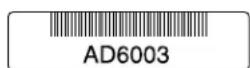
1600
Related Documentation
T1600 Router Description on page 3.
•Contacting Customer Support on page 529
- Returning a Hardware Component to Juniper Networks, Inc. on page 543
T1600 Component Serial Number Label Locations
• Control Board Serial Number Label on page 533
• CIP Serial Number Label on page 534
• Craft Interface Serial Number Label on page 534
• FPC Serial Number Label on page 535
• PIC Serial Number Label on page 536
• Power Supply Serial Number Label on page 537
- Routing Engine Serial Number Label on page 538
• SCG Serial Number Label on page 538
• SIB Serial Number Label on page 539
Control Board Serial Number Label
The location of the serial number label varies depending on the control board. The T-CB serial number is located on the top of the control board (see Figure 267 on page 533).
Figure 267: T-CB Serial Number Label
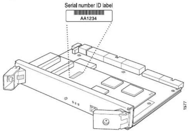
The LCC-CB serial number is located on the lower right side of the control board (see Figure 268 on page 534).
Figure 268: LCC-CB Serial Number Label

CIP Serial Number Label
The serial number label is located at the top of the left side of the CIP (see Figure 269 on page 534).
Figure 269: CIP Serial Number Label

Craft Interface Serial Number Label
The serial number is located on the back of the craft interface panel, behind the alarm LEDs (see Figure 270 on page 535).
Figure 270: Craft Interface Serial Number Label

FPC Serial Number Label
The location of the serial number label varies depending on the FPC:
- Type 1 FPCs: located near the top PIC slot
- Type 2 FPCs: located near the top PIC slot
- Type 3 FPCs: located center of the right side
• T640 Type 4 FPCs: located center left near the top of the FPC
• T1600 Type 4 FPCs: located lower right side
For example, Figure 271 on page 536 shows the serial number location for a T1600 Type 4 FPC.
Figure 271: Serial Number Label on a T1600 Type 4 FPC FPC4

Serial number ID label
PIC Serial Number Label
The exact location serial number label is different on different PICs, depending on the placement of components on the PIC board. In this example, the serial number label is located on the right side of the PIC (see Figure 272 on page 537), when the PIC is vertical oriented (as it would be installed in the router).
Figure 272: PIC Serial Number Label

Power Supply Serial Number Label
For the three-input 240-A DC power supply, the serial number label is located on the left side of the power supply faceplate (see Figure 273 on page 537).
Figure 273: Three-input 240-A Power Supply Serial Number Label

For the six-input DC power supply, the serial number label is located on the lower left side of the faceplate. (see Figure 274 on page 538).
Figure 274: DC Power Supply Serial Number Label

Routing Engine Serial Number Label
The serial number label is located on the right side of the top of the Routing Engine (see Figure 275 on page 538).
Figure 275: Routing Engine Serial Number Label

SCG Serial Number Label
The serial number is located on the top of the SCG, close to the midplane connector (see Figure 276 on page 539).
Figure 276: SCG Serial Number Label
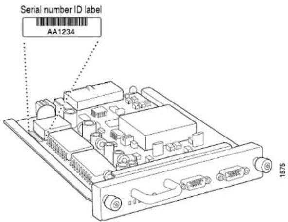
SIB Serial Number Label
For the standard SIB or SIB version B, the serial number label is located as shown in Figure 277 on page 539.
Figure 277: Standard SIB and SIB Version B Serial Number Label
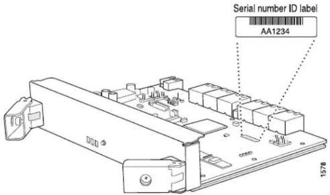
For the TXP-LCC-3D SIB, the serial number label is located as shown in Figure 278 on page 540.
Figure 278: TXP-LCC-3D Serial Number Label

Related Documentation
•T1600 Hardware Component Overview on page 15
- Locating T1600 Component Serial Numbers Using the CLI on page 531
CHAPTER 37
Packing and Returning Components
- Tools and Parts Required to Remove Components from a T1600 Router on page 541
- Packing the T1600 Router for Shipment on page 542
- Packing the T1600 Router Components for Shipment on page 543
- Returning a Hardware Component to Juniper Networks, Inc. on page 543
Tools and Parts Required to Remove Components from a T1600 Router
To remove components from the router or the router from a rack, you need the following tools and parts:
• 7/16-in. (11 mm) nut driver
- Blank panels to cover empty slots
- Electrostatic bag or antistatic mat, for each component
• Electrostatic discharge (ESD) grounding wrist strap
- Flat-blade (−) screwdriver
- Mechanical lift, if available
• Phillips (+) screwdrivers, numbers 1 and 2
- Rubber safety cap for fiber-optic interfaces or cable
- Wire cutters
- 2.5-mm flat-blade (−) screwdriver, for detaching alarm relay terminal block
Related Documentation
Tools and Parts Required for Replacing T1600 Hardware Components on page 302.
•Packing the T1600 Router for Shipment on page 542
•Packing the T1600 Router Components for Shipment on page 543
•Contacting Customer Support on page 529
Packing the T1600 Router for Shipment
To pack the router for shipment:
- Retrieve the shipping crate and packing materials in which the router was originally shipped. If you do not have these materials, contact your Juniper Networks representative about approved packaging materials.
- Attach an electrostatic discharge (ESD) grounding strap to your bare wrist, and connect the strap to one of the ESD points on the chassis.
- On the console or other management device connected to the master Routing Engine, enter CLI operational mode. To shut down the router software:
user@host> request system halt
(If two Routing Engines are installed, also issue the command on the backup Routing Engine.) Wait until a message appears on the console confirming that the operating system has halted.
The command shuts down the Routing Engine cleanly, so its state information is preserved. For more information about the command, see request system halt.

NOTE: The SIB might continue forwarding traffic for approximately 5 minutes after the request system halt command has been issued.
- For all power supplies, shut down power to the router by pressing the circuit breakers to the off (O) position, or the power switch to the standby position.
- Disconnect power from the router. For instructions, see:
- Removing a T1600 DC Power Supply Cable From a Three-Input 240-A DC Power Supply or Four-Input 240-A DC Power Supply on page 410
- Removing a T1600 Three-Phase Delta AC Power Supply Cord on page 433
- Removing a T1600 Three-Phase Wye AC Power Supply Cord on page 444
- Remove the cables that connect to all external devices. For instructions, see "Replacing a T1600 Console or Auxiliary Cable" on page 312, "Replacing a T1600 Management Ethernet Cable" on page 315, "Replacing the T1600 Alarm Relay Wires" on page 310, and "Replacing a T1600 PIC Cable" on page 389.
- Remove all Field Replaceable Units (FRUs) from the router.
- Remove the router from the rack:
- If you are using a mechanical lift, place the lift platform under the router, unscrew and remove the mounting screws from the rack, and move the router to the shipping crate.
- If you are not using a mechanical lift and the router weight is fully supported by a shelf or another router, unscrew and remove the mounting screws from the rack. Four people can then lift the router and move it to the shipping crate.
- If you are not using a mechanical lift and the router weight is not fully supported by a shelf or another router, four people should grasp the router while a fifth person unscrews and removes the mounting screws from the rack. The four lifters can then move the router to the shipping crate.
- Place the router in the shipping crate or onto the pallet. If on a pallet, bolt the router to the pallet.
- Cover the router with an ESD bag and place the packing foam on top of and around the router.
- Replace the accessory box on top of the packing foam.
- Securely tape the box closed or place the crate cover over the router.
- Write the RMA number on the exterior of the box to ensure proper tracking.
Related Documentation
T1600 Preventing Electrostatic Discharge Damage on page 552.
•Contacting Customer Support on page 529
Packing the T1600 Router Components for Shipment
To pack and ship individual components:
- When you return components, make sure they are adequately protected with packing materials and packed so that the pieces are prevented from moving around inside the carton.
- Use the original shipping materials if they are available.
- Place individual components in electrostatic bags.
- Write the RMA number on the exterior of the box to ensure proper tracking.

CAUTION: Do not stack any of the router components.
Related Documentation
Contacting Customer Support on page 529.
•Verifying the T1600 Router Parts Received on page 177
Returning a Hardware Component to Juniper Networks, Inc.
If a problem cannot be resolved by the JTAC technician, a Return Materials Authorization MO1i (RMA) is issued. This number is used to track the returned material at the factory and to return repaired or new components to the customer as needed.

NOTE: Do not return any component to Juniper Networks, Inc. unless you have first obtained an RMA number. Juniper Networks, Inc. reserves the right to refuse shipments that do not have an RMA. Refused shipments will be returned to the customer by collect freight.
For more information about return and repair policies, see the customer support Web page at http://www.juniper.net/support/guidelines.html.
For product problems or technical support issues, contact the Juniper Networks Technical Assistance Center (JTAC) using the Case Manager link at http://www.juniper.net/support/ or at 1-888-314-JTAC (within the United States) or 1-408-745-9500 (from outside the United States).
To return a hardware component:
- Determine the part number and serial number of the component.
- Obtain an RMA number from the Juniper Networks Technical Assistance Center (JTAC). You can send e-mail or telephone as described above.
- Provide the following information in your e-mail message or during the telephone call:
• Part number and serial number of component - Your name, organization name, telephone number, and fax number
• Description of the failure - The support representative validates your request and issues an RMA number for return of the component.
- Pack the component for shipment.
Related Documentation
- Contacting Customer Support on page 529
•Guidelines for Packing Router Components for Shipment
PART 8
Safety and Compliance Information
- General Safety Guidelines and Warnings on page 547
• Fire Safety Requirements on page 557
• Installation Safety Guidelines and Warnings on page 559 - Laser and LED Safety Guidelines and Warnings on page 565
- Maintenance and Operational Safety Warnings on page 569
• Electrical Guidelines and Warnings on page 575
• Agency Approvals and Compliance Statements on page 587
CHAPTER 38
General Safety Guidelines and Warnings
• Definition of Safety Warning Levels on page 547
- General Safety Guidelines for Juniper Networks Devices on page 549
- General Safety Warnings for Juniper Networks Devices on page 549
• T1600 Preventing Electrostatic Discharge Damage on page 552
Definition of Safety Warning Levels
The documentation uses the following levels of safety warnings:

NOTE: You might find this information helpful in a particular situation, or might otherwise overlook it.

CAUTION: You must observe the specified guidelines to avoid minor injury or discomfort to you, or severe damage to the hardware device.

WARNING: This symbol alerts you to the risk of personal injury from a laser.

WARNING: Thissymbolmeans danger. You are in a situationthatcould cause bodily injury. Before you work on any equipment, be aware of the hazards involved with electrical circuitry and be familiar with standard practices for preventing accidents.
Related Documentation
General Safety Warnings for Juniper Networks Devices on page 549.
• Installation Safety Warnings for Juniper Networks Devices on page 559
- Maintenance and Operational Safety Warnings for Juniper Networks Devices on page 569
•General Electrical Safety Warnings for Juniper Networks Devices on page 576
•DC Power Electrical Safety Warnings for Juniper Networks Devices on page 581
General Safety Guidelines for Juniper Networks Devices
The following guidelines help ensure your safety and protect the hardware equipment from damage. The list of guidelines might not address all potentially hazardous situations in your working environment, so be alert and exercise good judgment at all times.
- Perform only the procedures explicitly described in this documentation. Make sure that only authorized service personnel perform other system services.
- Keep the area around the chassis clear and free from dust before, during, and after installation.
- Keep tools away from areas where people could trip over them while walking.
- Do not wear loose clothing or jewelry, such as rings, bracelets, or chains, which could become caught in the chassis.
- Wear safety glasses if you are working under any conditions that could be hazardous to your eyes.
- Do not perform any actions that create a potential hazard to people or make the equipment unsafe.
- Never attempt to lift an object that is too heavy for one person to handle.
- Never install or manipulate wiring during electrical storms.
- Never install electrical jacks in wet locations unless the jacks are specifically designed for wet environments.
- Operate the hardware equipment only when the chassis is properly grounded.
- Do not open or remove chassis covers or sheet metal parts unless instructions are provided in this documentation. Such an action could cause severe electrical shock.
- Do not push or force any objects through any opening in the chassis frame. Such an action could result in electrical shock or fire.
- Avoid spilling liquid onto the chassis or onto any hardware component. Such an action could cause electrical shock or damage the hardware equipment.
- Avoid touching uninsulated electrical wires or terminals that have not been disconnected from their power source. Such an action could cause electrical shock.
Related Documentation
General Safety Warnings for Juniper Networks Devices on page 549.
General Safety Warnings for Juniper Networks Devices
• Qualified Personnel Warning on page 550
- Restricted Access Area Warning on page 550
Qualified Personnel Warning

WARNING: Only trained and qualified personnel should install or replace the hardware equipment.
Restricted Access Area Warning

WARNING: The hardware equipment is intended for installation in restricted access areas. A restricted access area is an area to which access can be gained only by service personnel through the use of a special tool, lock and key, or other means of security, and which is controlled by the authority responsible for the location.
Related Documentation
Installation Safety Warnings for Juniper Networks Devices on page 559.
- Maintenance and Operational Safety Warnings for Juniper Networks Devices on page 569
•General Electrical Safety Warnings for Juniper Networks Devices on page 576
•DC Power Electrical Safety Warnings for Juniper Networks Devices on page 581
T1600 Preventing Electrostatic Discharge Damage
Many router hardware components are sensitive to damage from static electricity. Some components can be impaired by voltages as low as 30 V. You can easily generate potentially damaging static voltages whenever you handle plastic or foam packing material or if you move components across plastic or carpets. Observe the following guidelines to minimize the potential for electrostatic discharge (ESD) damage, which can cause intermittent or complete component failures:
- Always use an ESD wrist strap or ankle strap, and make sure that it is in direct contact with your skin.

CAUTION: For safety, periodically check the resistance value of the ESD strap. The measurement should be in the range of 1 to 10 Mohms.
- When handling any component that has been removed from the chassis, verify that the equipment end of your ESD strap is attached to one of the ESD points on the chassis, which are shown in Figure 279 on page 553 and Figure 280 on page 554.
- Avoid contact between the component and your clothing. ESD voltages emitted from clothing can still damage components.
- When removing or installing a component, always place it component-side up on an antistatic surface, in an antistatic card rack, or in an electrostatic bag (see Figure 281 on page 554). If you are returning a component, place it in an electrostatic bag before packing it.
Figure 279: ESD Point on Front of the T1600 Router

Figure 280: ESD Point on Rear of the T1600 Router
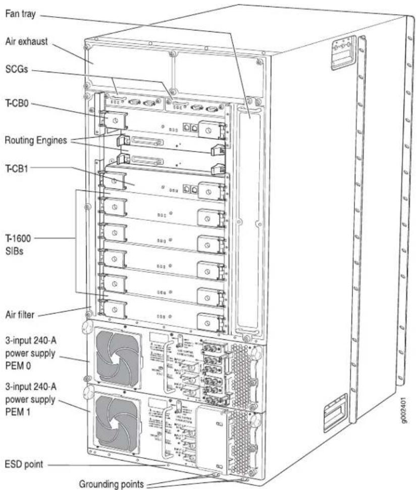
Figure 281: Placing a Component into an Electrostatic Bag
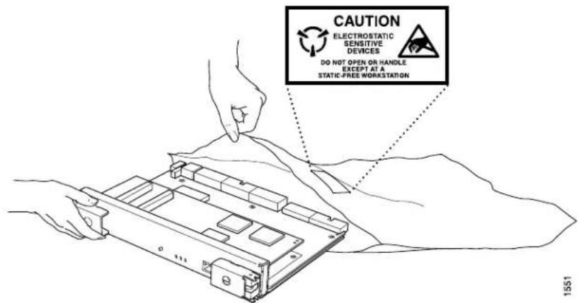
Related Documentation
•T1600 General Electrical Safety Guidelines on page 575
•T1600 Router Description on page 3
•Contacting Customer Support on page 529
CHAPTER 39
Fire Safety Requirements
- Fire Safety Requirements for Juniper Networks Devices on page 557
Fire Safety Requirements for Juniper Networks Devices
- General Fire Safety Requirements on page 557
• Fire Suppression on page 557
• Fire Suppression Equipment on page 557
General Fire Safety Requirements
In the event of a fire emergency involving network devices, the safety of people is the primary concern. Establish procedures for protecting people in a fire emergency, provide safety training, and properly provision fire-control equipment and fire extinguishers.
In addition, establish procedures to protect your equipment in a fire emergency. Juniper Networks products should be installed in an environment suitable for electronic equipment. We recommend that fire suppression equipment be available in the event of a fire in the vicinity of the equipment, and that you observe all local fire, safety, and electrical codes and ordinances when installing and operating your equipment.
Fire Suppression
In the event of an electrical hazard or an electrical fire, first turn power off to the equipment at the source. Then use a Type C fire extinguisher, which uses noncorrosive fire retardants, to extinguish the fire.
Fire Suppression Equipment
Type C fire extinguishers, which use noncorrosive fire retardants such as carbon dioxide (CO_2) and Halotron, are most effective for suppressing electrical fires. Type C fire extinguishers displace the oxygen from the point of combustion to eliminate the fire. For extinguishing fire on or around equipment that draws air from the environment for cooling, use this type of inert oxygen displacement extinguisher instead of an extinguisher that leave residues on equipment.
Do not use multipurpose Type ABC chemical fire extinguishers (dry chemical fire extinguishers) near Juniper Networks devices. The primary ingredient in these fire extinguishers is monoammonium phosphate, which is very sticky and difficult to clean.
In addition, in minute amounts of moisture, monoammonium phosphate can become highly corrosive and corrodes most metals.
Any equipment in a room in which a chemical fire extinguisher has been discharged is subject to premature failure and unreliable operation. The equipment is considered to be irreparably damaged.

NOTE: To keep warranties effective, donotuseadrychemical fire extinguisher to control a fire at or near a Juniper Networks device. If a dry chemical fire extinguisher is used, the unit is no longer eligible for coverage under a service agreement.
We recommend that you dispose of any irreparably damaged equipment in an environmentally responsible manner.
Related Documentation
•General Safety Guidelines for Juniper Networks Devices on page 549
•General Safety Warnings for Juniper Networks Devices on page 549
•General Electrical Safety Warnings for Juniper Networks Devices on page 576
•DC Power Electrical Safety Warnings for Juniper Networks Devices on page 581
CHAPTER 40
Installation Safety Guidelines and Warnings
• T1600 Chassis Lifting Guidelines on page 559
• Installation Safety Warnings for Juniper Networks Devices on page 559
T1600 Chassis Lifting Guidelines
- Before moving the router, follow the guidelines in the site preparation checklist to verify that the intended site meets the specified power, environmental, and clearance requirements.
- Do not attempt to lift a fully configured router by yourself. Using a mechanical lift to maneuver the router into a rack is recommended. If a lift cannot be used, a minimum of four people is required to lift the router, and you must remove components from the chassis before lifting.
- Before lifting or moving the router, disconnect all external cables.
- As when lifting any heavy object, lift most of the weight with your legs rather than your back. Keep your knees bent and your back relatively straight and avoid twisting your body as you lift. Balance the load evenly and be sure that your footing is solid.
Related Documentation
T1600 Site Preparation Requirements Checklist on page 129.
•Overview of Installing a T1600 Router Without a Mechanical Lift on page 201
•Overview of Installing a T1600 Router Using a Mechanical Lift on page 193
• Installation Safety Warnings for Juniper Networks Devices on page 559
Installation Safety Warnings for Juniper Networks Devices
Observe the following warnings before and during hardware equipment installation:
• Intra-Building Ports Warning on page 560
• Installation Instructions Warning on page 560
- Rack-Mounting Requirements and Warnings on page 560
- Ramp Warning on page 564
Intra-Building Ports Warning

WARNING: The intra-building ports of the equipment or subassembly are suitable for connection to intra-building or unexposed wiring or cabling only. The intra-building ports of the equipment or subassembly MUST NOT be metallically connected to interfaces that connect to the OSP or its wiring. These interfaces are designed for use as intra-building interfaces only (Type 2 or Type 4 ports as described in GR-1089) and require isolation from the exposed OSP cabling. The addition of Primary Protectors is not sufficient protection in order to connect these interfaces metallically to OSP wiring.
Installation Instructions Warning

WARNING: Read the installation instructions before you connect the hardware equipment to a power source.
Rack-Mounting Requirements and Warnings
Ensure that the equipment rack into which the chassis is installed is evenly and securely supported, to avoid the hazardous condition that could result from uneven mechanical loading.

WARNING: To prevent bodily injury when mounting or servicing the chassis in a rack, take the following precautions to ensure that the system remains stable. The following directives help maintain your safety:
- The chassis must be installed into a rack that is secured to the building structure.
- When mounting the chassis in a partially filled rack, load the rack from the bottom to the top, with the heaviest component at the bottom of the rack.
- If the rack is provided with stabilizing devices, install the stabilizers before mounting the chassis in the rack or servicing the hardware equipment.
WARNING: When installing the hardware equipment, do not use a ramp inclined at more than 10 degrees.
Related Documentation
•General Safety Guidelines for Juniper Networks Devices on page 549
•General Safety Warnings for Juniper Networks Devices on page 549
- Maintenance and Operational Safety Warnings for Juniper Networks Devices on page 569
CHAPTER 41
Laser and LED Safety Guidelines and Warnings
• T1600 General Laser Safety Guidelines on page 565
- Laser Safety Warnings for Juniper Networks Devices on page 566
T1600 General Laser Safety Guidelines
Devices with single-mode optical interfaces are equipped with laser transmitters, which are considered a Class 1 Laser Product by the U.S. Food and Drug Administration, and are evaluated as a Class 1 Laser Product according to EN 60825-1 +A11 +A2 requirements.
When working around devices with optical interfaces, observe the following safety guidelines to prevent eye injury:
- Do not look into unterminated ports or at fibers that connect to unknown sources.
- Do not examine unterminated optical ports with optical instruments.
- Avoid direct exposure to the beam.

WARNING: Unterminated optical connectors can emit invisible laser radiation. The lens in the human eye focuses all the laser power on the retina, so focusing the eye directly on a laser source—even a low-power laser—could permanently damage the eye.
Related Documentation
Connecting PIC Cables to the T1600 Router on page 236.
•Replacing a T1600 PIC on page 384
•Replacing a T1600 PIC Cable on page 389
•Replacing a T1600 PIC Transceiver
•General Safety Guidelines for Juniper Networks Devices on page 549
Laser Safety Warnings for Juniper Networks Devices
• Class 1 Laser Product Warning on page 566
• Class 1 LED Product Warning on page 566
• Laser Beam Warning on page 567
- Radiation from Open Port Apertures Warning on page 567
Class 1 Laser Product Warning

WARNING: Class 1 laser product.
Waarschuwing Klasse-1 laser produkt.
Class 1 LED Product Warning

WARNING: Class 1 LED product.
WARNING: Do not stare into the laser beam or view it directly with optical instruments.
Radiation from Open Port Apertures Warning

WARNING: Because invisible radiation might be emitted from the aperture of the port when no fiber cable is connected, avoid exposure to radiation and do not stare into open apertures.
Related Documentation
•General Safety Guidelines for Juniper Networks Devices on page 549
•General Safety Warnings for Juniper Networks Devices on page 549
•Installation Safety Warnings for Juniper Networks Devices on page 559
CHAPTER 42
Maintenance and Operational Safety Warnings
- Maintenance and Operational Safety Warnings for Juniper Networks Devices on page 569
Maintenance and Operational Safety Warnings for Juniper Networks Devices
As you maintain the hardware equipment, observe the following warnings:
• Battery Handling Warning on page 569
• Jewelry Removal Warning on page 570
• Lightning Activity Warning on page 571
- Operating Temperature Warning on page 572
• Product Disposal Warning on page 573
Battery Handling Warning

WARNING: Replacing the battery incorrectly might result in an explosion. Replace the battery only with the same or equivalent type recommended by the manufacturer. Dispose of used batteries according to the manufacturer's instructions.
Jewelry Removal Warning

WARNING: Before working on equipment that is connected to power lines, remove jewelry, including rings, necklaces, and watches. Metal objects heat up when connected to power and ground and can cause serious burns or weld the metal object to the terminals.
WARNING: Do not work on the system or connector disconnect cables during periods of lightning activity.
Operating Temperature Warning

WARNING: To prevent the hardware equipment from overheating, do not operate it in an area that exceeds the maximum recommended ambient temperature of 104^ F ( 40^ C). To prevent airflow restriction, allow at least 6 inches (15.2 cm) of clearance around the ventilation openings.
Product Disposal Warning

WARNING: Disposal of this product must be handled according to all national laws and regulations.
Related •General Safety Guidelines for Juniper Networks Devices on page 549 Documentation •General Safety Warnings for Juniper Networks Devices on page 549
CHAPTER 43
Electrical Guidelines and Warnings
• T1600 General Electrical Safety Guidelines on page 575
- General Electrical Safety Warnings for Juniper Networks Devices on page 576
• T1600 DC Power Electrical Safety Guidelines on page 580
• DC Power Electrical Safety Warnings for Juniper Networks Devices on page 581
- Site Electrical Wiring Guidelines for Juniper Networks Devices on page 584
T1600 General Electrical Safety Guidelines
- Install the router in compliance with the following local, national, or international electrical codes:
- United States—National Fire Protection Association (NFPA 70), United States National Electrical Code.
• Canada—Canadian Electrical Code, Part 1, CSA C22.1. - Other countries—International Electromechanical Commission (IEC) 60364, Part 1 through Part 7.
- Locate the emergency power-off switch for the room in which you are working so that if an electrical accident occurs, you can quickly turn off the power.
- Do not work alone if potentially hazardous conditions exist anywhere in your workspace.
- Never assume that power is disconnected from a circuit. Always check the circuit before starting to work.
- Carefully look for possible hazards in your work area, such as moist floors, ungrounded power extension cords, and missing safety grounds.
- Operate the router within marked electrical ratings and product usage instructions.
- For the router and peripheral equipment to function safely and correctly, use the cables and connectors specified for the attached peripheral equipment, and make certain they are in good condition.
Many router components can be removed and replaced without powering off or disconnecting power to the router. Never install equipment if it appears damaged.
Related Documentation
T1600 Router Description on page 3.
•General Safety Guidelines for Juniper Networks Devices on page 549
•T1600 Site Preparation Requirements Checklist on page 129
•T1600 Field-Replaceable Units on page 301
General Electrical Safety Warnings for Juniper Networks Devices
• Grounded Equipment Warning on page 576
• Grounding Requirements and Warning on page 577
• Midplane Energy Hazard Warning on page 577
- Multiple Power Supplies Disconnection Warning on page 578
• Power Disconnection Warning on page 578
Grounded Equipment Warning

WARNING: The network device is intended to be grounded. Ensure that the network device is connected to earth ground during normal use.
Grounding Requirements and Warning
An insulated grounding conductor that is identical in size to the grounded and ungrounded branch circuit supply conductors, but is identifiable by green and yellow stripes, is installed as part of the branch circuit that supplies the unit. The grounding conductor is a separately derived system at the supply transformer or motor generator set.

WARNING: When installing the network device, you must always make the ground connection first and disconnect it last.
Midplane Energy Hazard Warning

WARNING: High levelsof electrical energya redistributed acrossthe midplane. Be careful not to contact the midplane connectors, or any component connected to the midplane, with any metallic object while servicing components.
Multiple Power Supplies Disconnection Warning

WARNING: The network device has more than one power supply connection. All connections must be removed completely to remove power from the unit completely.
Power Disconnection Warning

WARNING: Before working on the chassis or near power supplies, switch off the power at the DC circuit breaker.
Related Documentation
DC Power Electrical Safety Warnings for Juniper Networks Devices on page 581.
T1600 DC Power Electrical Safety Guidelines
The following electrical safety guidelines apply to a DC-powered router:
- Be sure to connect the ground wire or conduit to a solid office (earth) ground. A closed loop ring is recommended for terminating the ground conductor at the ground stud.
- A DC-powered router is equipped with a DC terminal block that is rated for the power requirements of a maximally configured router.
To supply sufficient power, terminate the DC input wiring on a facility DC source capable of supplying at least 67 A @ -48 VDC per input for the three-input 240-A DC power supply, 48 A @ -48 VDC per input for the four-input 240-A DC power supply, or 56 A @ -48 VDC per input for the six-input DC power supply.
- Incorporate an easily accessible disconnect device into the facility wiring. In the United States and Canada, the -48 VDC facility should be equipped with a circuit breaker rated a minimum of 125% of the power provisioned for the input in accordance with the National Electrical Code in the US and the Canadian Electrical Code in Canada.

WARNING: For the six-input DC powersupply, failure to providetherequired circuit breaker or current-limiting fuse for each DC power cable can cause injury or damage to equipment.
For the six-input DC power supply, each 48 VDC facility DC source input power cable must be equipped with a current-limiting fuse or circuit breaker external to the Juniper Networks equipment rated at 80 A (-48 VDC) maximum. The voltage rating of the facility DC source circuit breaker must be 80 V minimum. We recommend an 80 A circuit breaker or current-limiting fuse rated for each 60 A DC power cable.
We recommend that the 48 VDC facility DC source be equipped with a circuit breaker rated at 80 A (-48 VDC) minimum for the three-input 240-A DC power supply or 60 A (-48 VDC) minimum for the four-input 240-A power supply, or as required by local code.
- Run two wires from the circuit breaker box to a source of 48 VDC. Use appropriate gauge wire to handle up to 80 A for a three-input 240-A DC power supply or 60 A for a four-input 240-A power supply.
- A DC-powered router that is equipped with a DC terminal block is intended only for installation in a restricted access location. In the United States, a restricted access area is one in accordance with Articles 110-16, 110-17, and 110-18 of the National Electrical Code ANSI/NFPA 70.

NOTE: Primary overcurrent protection is provided by the building circuit breaker. This breaker should protect against excess currents, short circuits, and earth faults in accordance with NEC ANSI/NFPA70.
- Ensure that the polarity of the DC input wiring is correct. Under certain conditions, connections with reversed polarity might trip the primary circuit breaker or damage the equipment.
- For personal safety, connect the green and yellow wire to safety (earth) ground at both the router and the supply side of the DC wiring.
- The marked input voltage of -48 VDC for a DC-powered router is the nominal voltage associated with the battery circuit, and any higher voltages are only to be associated with float voltages for the charging function.
- Because the router is a positive ground system, you must connect the positive lead to the terminal labeled RTN, the negative lead to the terminal labeled -48V, and the earth ground to the chassis grounding points.
Related Documentation
Site Electrical Wiring Guidelines for Juniper Networks Devices on page 584.
•T1600 General Electrical Safety Guidelines on page 575
•T1600 DC Power System Electrical Specifications on page 137
DC Power Electrical Safety Warnings for Juniper Networks Devices
When working with DC-powered equipment, observe the following warnings:
• DC Power Copper Conductors Warning on page 581
• DC Power Disconnection Warning on page 582
• DC Power Wiring Terminations Warning on page 583
DC Power Copper Conductors Warning

WARNING: Use copper conductors only.
DC Power Disconnection Warning

WARNING: Before performing any procedures on powersupplies, ensure that power is removed from the DC circuit. To ensure that all power is off, locate the circuit breaker on the panel board that services the DC circuit, switch the circuit breaker to the off position, and tape the switch handle of the circuit breaker in the off position.
DC Power Wiring Terminations Warning

WARNING: When stranded wiring is required, use approved wiring terminations, such as closed-loop or spade-type with upturned lugs. These terminations should be the appropriate size for the wires and should clamp both the insulation and conductor.
Related Documentation
General Safety Warnings for Juniper Networks Devices on page 549.
•General Electrical Safety Warnings for Juniper Networks Devices on page 576
Site Electrical Wiring Guidelines for Juniper Networks Devices
• Distance Limitations for Signaling on page 584
• Radio Frequency Interference on page 585
• Electromagnetic Compatibility on page 585
Distance Limitations for Signaling
Improperly installed wires can emit radio interference. In addition, the potential for damage from lightning strikes increases if wires exceed recommended distances or if wires pass between buildings. The electromagnetic pulse (EMP) caused by lightning can damage unshielded conductors and destroy electronic devices. If your site has previously experienced such problems, you might want to consult experts in electrical surge suppression and shielding.
Radio Frequency Interference
You can reduce or eliminate the emission of radio frequency interference (RFI) from your site wiring by using twisted-pair cable with a good distribution of grounding conductors. If you must exceed the recommended distances, use a high-quality twisted-pair cable with one ground conductor for each data signal when applicable.
Electromagnetic Compatibility
If your site is susceptible to problems with electromagnetic compatibility (EMC), particularly from lightning or radio transmitters, you might want to seek expert advice. Strong sources of electromagnetic interference (EMI) can destroy the signal drivers and receivers in the network device and conduct power surges over the lines into the equipment, resulting in an electrical hazard. It is particularly important to provide a properly grounded and shielded environment and to use electrical surge-suppression devices.

CAUTION: To comply with intrabuilding lightning and surge requirements, intrabuilding wiring must be shielded, and the shield for the wiring must be grounded at both ends.

WARNING: The intrabuilding port(s) of the equipment or subassembly is suitable for connection to intrabuilding or unexposed wiring or cabling only. The intrabuilding port(s) of the equipment or subassembly MUST NOT be metallically connected to interfaces that connect to the OSP or its wiring. These interfaces are designed for use as intrabuilding interfaces only (Type 2 or Type4portsas described in GR-1089-CORE, Issue 4) and require isolation from the exposed OSP cabling. The addition of primary protectors is not sufficient protection in order to connect these interfaces metallically to OSP wiring.
Related •General Electrical Safety Guidelines and Electrical Codes for Juniper Networks Devices Documentation
CHAPTER 44
Agency Approvals and Compliance Statements
• T1600 Agency Approvals on page 587
- Compliance Statements for EMC Requirements for Juniper Networks Devices (Canada) on page 588
• T1600 Compliance Statements for EMC Requirements (European Community) on page 588
• Compliance Statements for EMC Requirements for Juniper Networks Devices (Israel) on page 589
- Compliance Statements for EMC Requirements for Juniper Networks Devices (Japan) on page 589
- Compliance Statements for EMC Requirements for Juniper Networks Devices (United States) on page 589
- Compliance Statements for Environmental Requirements for Juniper Networks Devices on page 590
• T1600 Compliance Statements for NEBS on page 590
• T1600 Compliance Statements for Acoustic Noise on page 590
T1600 Agency Approvals
The router complies with the following standards:
- Safety
• CAN/CSA-22.2 No. 60950-1-07/UL 60950-1, 2nd Ed., Safety of Information Technology Equipment
• EN 60825-1 +A1+A2 (1994) Safety of Laser Products - Part 1: Equipment Classification
- EMC
• AS/NZS 3548 Class A (Australia/New Zealand)
• EN55022 Class A (Europe)
• FCC Part 15 Class A (USA)
• VCCI Class A (Japan)
- Immunity
• EN-61000-3-2 Power Line Harmonics
• EN-61000-3-3 Voltage Fluctuations and Flicker
• EN-61000-4-2 ESD
• EN-61000-4-3 Radiated Immunity
• EN-61000-4-4 EFT
• EN-61000-4-5 Surge
• EN-61000-4-6 Low Frequency Common Immunity
• EN-61000-4-11 Voltage Dips and Sags - ETSI EN-300386-2 Telecommunication Network Equipment. Electromagnetic Compatibility Requirements
- NEBS
- GR-1089-Core: EMC and Electrical Safety for Network Telecommunications Equipment
• SR-3580 NEBS Criteria Levels (Level 3 Compliance)
• GR-63-Core: NEBS, Physical Protection
Related Documentation
T1600 Router Description on page 3.
•T1600 DC Power System Electrical Specifications on page 137
Compliance Statements for EMC Requirements for Juniper Networks Devices (Canada)
This Class A digital apparatus complies with Canadian ICES-003.
Related Documentation
- Compliance Statements for EMC Requirements for Juniper Networks Devices (Israel) on page 589
•Compliance Statements for EMC Requirements for Juniper Networks Devices (Japan) on page 589
•Compliance Statements for EMC Requirements for Juniper Networks Devices (United States) on page 589
T1600 Compliance Statements for EMC Requirements (European Community)
This is a Class A product. In a domestic environment this product may cause radio interference in which case the user may be required to take adequate measures.
Related Documentation
T1600 Agency Approvals on page 587.
Compliance Statements for EMC Requirements for Juniper Networks Devices (Israel)
הַרְשָׁה
Related Documentation
Translation from Hebrew—Warning: This product is Class A. In residential environments, the product may cause radio interference, and in such a situation, the user may be required to take adequate measures.
• Compliance Statements for EMC Requirements for Juniper Networks Devices (Canada) on page 588
•Compliance Statements for EMC Requirements for Juniper Networks Devices (Japan) on page 589
•Compliance Statements for EMC Requirements for Juniper Networks Devices (United States) on page 589
Compliance Statements for EMC Requirements for Juniper Networks Devices (Japan)
Translation from Japanese—This is a Class A product. In a domestic environment this product may cause radio interference in which case the user may be required to take adequate measures. VCCI-A
Related Documentation
• Compliance Statements for EMC Requirements for Juniper Networks Devices (Canada) on page 588
•Compliance Statements for EMC Requirements for Juniper Networks Devices (Israel) on page 589
•Compliance Statements for EMC Requirements for Juniper Networks Devices (United States) on page 589
Compliance Statements for EMC Requirements for Juniper Networks Devices (United States)
The hardware equipment has been tested and found to comply with the limits for a Class A digital device, pursuant to Part 15 of the FCC Rules. These limits are designed to provide reasonable protection against harmful interference when the equipment is operated in a commercial environment. This equipment generates, uses, and can radiate radio
frequency energy and, if not installed and used in accordance with the instruction manual, may cause harmful interference to radio communications. Operation of this equipment in a residential area is likely to cause harmful interference in which case the user will be required to correct the interference at his own expense.
Related Documentation
•Site Electrical Wiring Guidelines for Juniper Networks Devices on page 584
•General Safety Guidelines for Juniper Networks Devices on page 549
•General Safety Warnings for Juniper Networks Devices on page 549
Compliance Statements for Environmental Requirements for Juniper Networks Devices
Batteries in this product are not based on mercury, lead, or cadmium substances. The batteries used in this product are in compliance with EU Directives 91/157/EEC, 93/86/EEC, and 98/101/EEC. The product documentation includes instructional information about the proper method of reclamation and recycling.
Related Documentation
General Safety Guidelines for Juniper Networks Devices on page 549.
•General Safety Warnings for Juniper Networks Devices on page 549
T1600 Compliance Statements for NEBS
- The equipment is suitable for installation as part of the Common Bonding Network (CBN).
- The equipment is suitable for installations in Network Telecommunication Facilities.
- The equipment is suitable for installation in locations where the National Electrical Code (NEC) applies.
- The battery return connection is to be treated as an isolated DC return (DC-I), as defined in GR-1089-CORE.
- For Juniper systems with AC power supplies, an external surge protective device (SPD) must be used at the AC power source.
Related Documentation
T1600 Agency Approvals on page 587.
T1600 Compliance Statements for Acoustic Noise
The emitted sound pressure resulted in 71.2 dB(A) per EN ISO 7779.
Related Documentation
•T1600 Router Description on page 3
•T1600 Physical Specifications on page 131
PART 9
Index
- Index on page 595
Index
Symbols
, comments in configuration statements......xxxi
( ), in syntax descriptions......xxxi
< >, in syntax descriptions.....xxxi
[ ], in configuration statements.....xxxi
{ }, in configuration statements.....xxxi
I (pipe), in syntax descriptions......xxxi
A
AC plug types....151
AC power cords specifications....151
AC power supply cord specifications....151
accessory box parts list....177 removing....176
agency approvals....587
air filters maintaining....476 replacing....305, 307
airflow required clearance around chassis for......135
alarms cutoff/lamp test button....33
handling by Routing Engine....7
LEDs (red and yellow) on craft interface....33
messages, list of....506
mode for LCD....33
relay contacts....25, 27 connecting/disconnecting wire....310
wire specifications....167 temperature, displaying....507, 513
altitude, acceptable range....130
antistatic mat, using....552
approvals, agency....587
architecture data flow....9
Packet Forwarding Engines....8
ASICs
Layer2/Layer 3 Packet Processing ASIC....8
Queuing and Memory Interface ASIC....8
Switch Interface ASIC....8
T Series Internet Processor....8
ATM analyzer, use of....488
attenuation in fiber-optic cable....162
auxiliary port....25
auxiliary port (for Routing Engine management) cable
connection during initial installation......232
connector pinouts (DB-9)....168
replacement instructions....312
specifications....167
B
battery environmental compliance....590
handling warning....569
lithium....590
booting the router....251, 257
braces, in configuration statements.....xxxi
brackets angle, in syntax descriptions....xxxi square, in configuration statements....xxxi
C
cable auxiliary or console port (for Routing Engine management) replacing....312
cover installation....236
Ethernet port (for Routing Engine management) replacing....315
fiber-optic cleaning instructions for transceivers....488
PIC connecting during maintenance....390 disconnecting....389 maintaining....488
cable cover installation....236
cable management system
fiber-optic cable, use with....488
front
description....23
removal....209
cables
auxiliary or console port (for Routing Engine management)
connecting during initial installation......232
Ethernet port (for Routing Engine management)
connecting during initial installation......234
fiber-optic
attenuation....162
dispersion....162
multimode and single-mode....162
transmission distance, maximum....162
wavelength ranges....162
case number, for JTAC....529
chassis....19
alarm messages See alarm, messages
ESD points....19
grounding points....19
installing in rack....196
weight....131
checklist for site preparation....129
chromatic dispersion in fiber-optic cable....162
CIP
alarm relay contacts....25, 27
description....25
replacing....317
Routing Engine ports....25
Class 1 laser warning....566
Class 1 LED warning....566
cleaning
fiber-optic array cable 496
fiber-optic array ports....496
cleaning instructions
fiber-optic transceivers....488
clearance, around rack....135
CLI
as troubleshooting tool....503
command
to display chassis alarm messages......506
to display FPC status....480
to display PIC status....488
to display serial number....531
commands
ping....503
show chassis alarms....506
show chassis fpc
for FPC status....480
show chassis fpc pic-status....488
show chassis hardware....531
traceroute....503
comments, in configuration statements.....xxxi
compatibility, electromagnetic....584
compliance
EMC (electromagnetic compatibility)
requirements (Canada)......588
EMC requirements....588
EMC requirements (Israel)....589
EMC requirements (Japan)....589
EMC requirements (United States)....589
general standards....587
components
cable management system
front....23
chassis....19
CIP 25
cooling system....37
field replacement....301
FPCs....73
host subsystem....41
midplane....21
overview....15
packing for shipment....543
PICs....86
power supplies....105, 106
redundancy....5
Routing Engine....42
SCG....28
T1600-SIB....120
TXP-T1600 SIB....121
configuration
files, storage by Routing Engine....7
Connector Interface Panel See CIP
console port (for Routing Engine management)
cable
connection during initial installation......232
connector pinout (DB-9)....168
connector pinout (RJ-45)....168
replacement instructions....312
specifications....167
control boards....67, 69
maintaining....477, 487
taking offline....349
See also LCC-CBs
See also T-CBs
conventions
text and syntax....XXX
cooling system
description....37
troubleshooting....507, 513
copper conductors warning (DC power)....581
cord
power See AC power cord
craft interface
alarm cutoff/lamp test button....33
FPC LEDs....35
FPC online/offline buttons....31
host subsystem LEDs....34
LCD....32
LEDs
alarm (red and yellow)....33
replacing....296, 320
curly braces, in configuration statements.....xxxi
customer support.....xxxii
contacting....529
contacting JTAC....xxxii
D
DB-9 cable connector pinouts (auxiliary and console ports)....168
DC power
copper conductors warning....581
disconnection warning....578
grounding equipment warning....576
grounding requirements warning....577
power supplies disconnection warning......578
removal warning....582
requirements for hardware components.....140
specifications....144
wiring terminations warning....583
DC power cables
lugs....144
specifications....144
DC power configuration
five 60-A inputs....266
DC power connections
five 60-A inputs....247
six 60-A inputs....243
DC power supplies
multiple disconnection warning....578
DC power supply
cables See DC power cables
dispersion in fiber-optic cable....162
documentation
comments on.....xxxi
E
earthquakes
site preparation for....133
tested toleration for seismic....130
EIA rack standards....133
electricity
safety warnings....576
site wiring guidelines....584
electromagnetic
compatibility See EMC (electromagnetic compatibility)
pulse....584
electrostatic bag
using to store components....552
em0....55
EMC (electromagnetic compatibility)
compliance with requirements (Canada)......588
compliance with requirements (Israel)....589
compliance with requirements (Japan)....589
compliance with requirements (United States)....589
suppression....584
EMC (EMI)
compliance with requirements....588
standards....587
EMP (electromagnetic pulse)....584
environmental specifications....130
ESD
preventing damage to components by....552
Ethernet port (for Routing Engine management) cable
connection during initial installation......234
replacement instructions....315
specifications....167
description....25
ETSI rack standards....133
F
fan trays
description....37
maintaining....478
replacing....325, 344
troubleshooting....507, 513
fiber-optic
power budget calculation....163
fiber-optic array cable
cleaning....496
testing....524
fiber-optic array loopback adapter....524
fiber-optic array loopback connector....523
fiber-optic array ports
cleaning....496
fiber-optic array switching plane ports
testing....523
field-replaceable units....301
fire safety requirements....557
Flexible PIC Concentrators See FPCs
font conventions......XXX
FPCs....73
components....73
LEDs....35
maintenance....480
online/offline buttons....31
replacing....377
status, checking....480, 515
troubleshooting....515
types....84
fxp0....55
G
grounding
equipment warning....576
requirements warning....577
grounding (electrical) specifications
DC-powered router....132
grounding cables
lug....132
guidelines
electrical cable and wiring....584
safety 549
H
hardware components
power requirements....140
higher-order mode loss (HOL)....162
host subsystem
description....41
LEDs....34
maintaining....486
taking offline....349
hot-pluggable components, description....301
humidity (relative), acceptable....130
|
immunity standards....587
installation
AC power, connecting....253, 255
DC power, connecting....240
parts received, verifying....177
PICs, connecting....236
unpacking the router....176
installation handle
attach....195
remove....198
installation instructions
alarm relay contact wires during initial installation....235
for maintenance or replacement....310
tools required....232
cable, auxiliary or console port (for Routing
Engine management)
during initial installation....232
for maintenance or replacement....312
tools required....232
cable, Ethernet port (for Routing Engine management)
during initial installation....234
for maintenance or replacement......315
tools required....232
cable, PIC
for maintenance or replacement....390
SFP 464
XENPAK module....469
XFP 466
installation warning....560
instructions
cleaning See cleaning instructions
maintenance
PIC 488
packing
router for shipment....542
interface
network....162
interference
electromagnetic....584
radio frequency....584
J
jewelry removal warning....570
Juniper Networks Technical Assistance Center (JTAC)....503
Junos OS modularity and scalability....7
L
laser beam warning....567 Class 1 laser warning....566
LCC-CBs components....69 description....69 LEDs....70 taking offline....349
LCD on craft interface alarm mode....33 description....32 idle mode....32
LEDs alarm (red and yellow on craft interface) description....33
Class 1 LED warning....566
FPC 35
host subsystem....34
LCC-CB....70
on components....505
on craft interface....504
power supplies....108, 111, 117
safety warnings....566
SCG....30
SIB....35
sonet clock generator....30
T-CB....68
T1600-SIB....121
TXP-LCC-3D SIBs....124
TXP-T1600-SIB....122
lightning activity warning....571
line-card chassis control boards....69 See also LCC-CBs
link loss, calculating....164
lithium battery compliance....590
lug for grounding cables....132
lugs for DC power cables....144
M
maintaining air filters....476 control boards....477, 487 fan trays....478
host subsystem....486
LCC-CBs....477, 487
power supplies....490
SCGs....495
SIBs....495
T-CBs....477, 487
maintenance guidelines cable PIC....488
FPC 480
PICs 488
warnings....569
management interface....55 em0....55 fxp0....55
manuals comments on.....xxxi
midplane....21 description....21 functions....21
midplane energy hazard warning....577
modal dispersion in fiber-optic cable....162
mode loss, higher-order....162
multimode fiber-optic cable See cables, fiber-optic
N
NEBS standards....587
O
open-frame rack See rack operating temperature warning....572
P
Packet Forwarding Engines architecture and data flow......8
parentheses, in syntax descriptions.....xxxi
PC card, replacing....367
PEMs see power supplies....105, 106
PICs....86 ATM, use of analyzer....488
cable installation instructions....390 removal instructions....389
connecting....236
description....86
maintenance....488
replacing....384
SONET/SDH
alarm messages....506
analyzer, use of....488
status, checking....488, 515
troubleshooting....519
ping command....503
pinouts
DB-9 cable connector ports
(auxiliary/console)....168
RJ-45 Ethernet cable connector port....168
plug types
AC....151
power
budget calculation....163
cords See AC power cord;
DC
requirements for hardware
components....140
disconnection warning (DC power)....578
margin calculation....164
surges....584
power supplies
cable
replacing....409
cables See DC power cables
description....105, 106
LEDs....108, 111, 117
maintaining....490
power system
troubleshooting....516
powering off the router....258
powering on the router....251, 257
product disposal warning....573
Q
qualified personnel warning....550
R
rack
clearance around, required....135
front-mount flange hole spacing....133
mounting bracket hole spacing....133
securing to building....133
size and strength required....133
standards, EIA and ETSI....133
rack mounting warning....560
radiation warning....567
radio frequency interference, preventing....584
ramp warning....564
redundancy....5
relative humidity, acceptable....130
removal instructions
alarm relay contact wires....310
cable
auxiliary or console port (for Routing
Engine management)....312
Ethernet port (for Routing Engine
management)....315
PIC....389
SFP 463
XENPAK module....468
XFP 465
replacing
air filters....305, 307
CIP 317
craft interface....320
fan trays....325, 344
FPCs....377
PC card....367
PICs....384
power supply cable....409
Routing Engine....356
SCGs....321
T-CBs....352
T1600-SIBs....449
TXP-LCC-3D SIBs....456
TXP-T1600 SIBs....452
requirements
fire safety....557
restricted access warning....550
RFI (radio frequency interference)....584
RJ-45 cable connector pinouts....168
router
component overview....15
parts list....177
unpacking....176
weight....131
Routing Engine
alarm handling by....7
components....43
configuration files, storage....7
description....42
maintaining....486, 493
management ports
cable and wire specifications....167
packet counting....7
ports on CIP
console port....25
replacing....356
routing
table maintenance....7
taking offline....349
S
safety guidelines
general....549
safety standards.
safety warnings....
See also warnings
SCGs
components....28
description....28
LEDs....30
maintaining....495
replacing....321
seismic earthquake.
serial number
in output from show chassis hardware
command....531
SFP
installation instructions....464
removal instructions....463
shipping crate
repacking....542
unpacking....176
weight....176
show chassis alarms
show chassis fpc command
for FPC status....480
show chassis fpc de
show chassis fpc pic
show chassis hardw
SIBs
description....119
LEDs....35
maintaining....495
replacing T1600-SIBs....449
replacing TXP-LCC-3D SIBs....456
replacing TXP-T1600 SIBs....452
supported for T1600 routers....119
T1600-SIB components....120
troubleshooting....520
TXP-LCC-3D components....123
TXP-T1600 components....121
signal dispersion..
signaling, distance limitations
single-mode fiber-optic cable See cables,
fiber-optic
site
electrical wiring guidelines....584
environmental specifications....130
preparation
checklist....129
small form-factor pluggable See SFP See XFP
SONET Clock Generators See SCGs
SONET/SDH analyzer, use of....488
specifications
AC power cord....151
cable....162
power....144
Routing Engine management ports......167
clearance around rack....135
electrical....151
environmental....130
power
drawn by hardware components......140
power system....140
rack
connection to building structure....133
front-mount flange hole spacing....133
mounting bracket hole spacing....133
size and strength....133
thermal output....130
wires to external alarm-reporting devices......167
standards compliance....587
startup, system
monitoring....251, 257
support, technical See technical support
surge protection....584
Switch Interface ASIC....8
Switch Interface Boards See SIBs
syntax conventions......XXX
T
T Series Internet Processor....8
T-CBs
components....67
description....67
LEDs....68
replacing....352
taking offline....349
T1600-SIBs
components....120
description....120
LEDs....121
maintaining....495
replacing....449
verifying installation....451
taking components offline
FPCs....31
taking host subsystem offline....349
technical support
contacting JTAC....xxxii
telco rack See rack
temperature, acceptable range....130
testing
fiber-optic array cable....524
fiber-optic array switching plane port....523
thermal output....130
tolerances....130
tools required
chassis
returning for repair or replacement......541
hardware components
returning for repair or replacement....541
replacement....302
traceroute command....503
transmission distances, fiber-optic cable....162
troubleshooting
CLI commands....503
cooling system....507, 513
fans....507, 513
FPCs....515
PIC....519
power system....516
SIBs....520
TXP-LCC-3D
description....123
TXP-LCC-3D SIBs
LEDs....124
replacing....456
TXP-T1600 SIBs
components....121
description....121
LEDs....122
maintaining....495
replacing....452
U
U (rack unit)....133
unpacking the router....176
W
warnings
battery handling....569
Class 1 laser....566
Class 1 LED....566
copper conductors (DC power)....581
electrical....576
grounding....577
grounding equipment 576
installation....560
jewelry removal....570
laser and LED....566
laser beam....567
levels defined....547
lightning activity....571
maintenance and operational....569
midplane energy hazard 577
multiple power supplies disconnection....578
operating temperature....572
power disconnection....578
power removal....582
product disposal....573
qualified personnel....550
rack mounting....560
radiation....567
ramp....564
restricted access....550
wiring terminations (DC power)......583
wavelength ranges supported by fiber-optic
cable....162
wiring
electrical See electricity
terminations warning (DC power)....583
X
XENPAK module....467
installation instructions....469
removal instructions....468
XFP
installation instructions....466
removal instructions....465

- END USER LICENSE AGREEMENT
- Table of Contents
- Part 1 Overview
- Chapter 4 Cooling System Components and Descriptions ..... 37
- Chapter 5 Host Subsystem Components and Descriptions ..... 4
- Chapter 6 Line Card Components and Descriptions
- Chapter 7 Power System Components and Descriptions ..... 105
- Chapter 8 Switch Fabric Components and Descriptions ..... 1
- Part 2 Site Planning, Preparation, and Specifications
- Chapter 9 Preparation Overview ...... 129
- Chapter 10 DC Power Specifications and Requirements ..... 1
- Chapter 11 AC Power Specifications and Requirements ..... 14
- Chapter 12 Network Cable and Transceiver Specifications ..... 15
- Chapter 13 Management Cable Specifications and Pinouts ..... 167
- Part 3 Initial Installation and Configuration
- Chapter 14 T1600 Router Installation Overview . . . . . . . . . . . . . . . . . . . . . . . . . . . . .
- Chapter 15 Unpacking the T1600 Router . . . . . . . . . . . . . . . . . . . . . . . . . . . . . . . . . .
- Chapter 16 Installing the T1600 Mounting Hardware . . . . . . . . . . . . . . . . . . . . . . . . . .
- Chapter 17 Installing the T1600 Router into a Rack . . . . . . . . . . . . . . . . . . . . . . . . . . .
- Chapter 18 Installing the T1600 Router into a Rack Using a Mechanical Lift . . . . . . . 193
- Chapter 19 Installing the T1600 Router into a Rack Without a Mechanical Lift . . . . . 201
- Chapter 23 Configuring the JUNOS Software . . . . . . . . . . . . . . . . . . . . . . . . . . . . . . . .
- Chapter 24 Upgrading to a T1600 Router from a T640 Router . . . . . . . . . . . . . . . . . . . . . . . . . . . . . . . . 26
- Part 4 Installing and Replacing Components
- Chapter 25 Overview of Installing and Replacing Components ..... 301
- Chapter 26 Replacing Chassis Components
- Chapter 27 Replacing Cooling System Components
- Chapter 29 Replacing Line Card Components .....
- Chapter 30 Replacing Power System Components .....
- Chapter 31 Replacing Switch Fabric Components
- Part 5 Maintaining the Chassis and Components
- Chapter 32 Routine Maintenance Procedures
- Chapter 33 Maintaining Components
- Part 6 Troubleshooting Hardware
- Chapter 34 Troubleshooting Components
- Part 7 Contacting Customer Support and Returning the Chassis or Components
- Chapter 35 Contacting Customer Support
- Chapter 36 Locating Component Serial Numbers .....
- Chapter 37 Packing and Returning Components .....
- Part 8 Safety and Compliance Information
- Chapter 38 General Safety Guidelines and Warnings . . . . . . . . . . . . . . . . . . . . . . . . . .
- Chapter 39 Fire Safety Requirements .... 557
- Chapter 40 Installation Safety Guidelines and Warnings ..... 5
- Chapter 41 Laser and LED Safety Guidelines and Warnings ..... 5
- Chapter 42 Maintenance and Operational Safety Warnings . . . . . . . . . . . . . . . . . . . . . . . . . . . . . . . . . . . . . . . . . . . . . . 56
- Chapter 43 Electrical Guidelines and Warnings .....
- Chapter 44 Agency Approvals and Compliance Statements ..... 587
- Part 9 Index
- List of Figures
- Chapter 1 System Overview and Architecture .....
- Chapter 3 Chassis Components and Descriptions .....
- Chapter 6 Line Card Components and Descriptions .....
- Chapter 18 Installing the T1600 Router into a Rack Using a Mechanical Lift ..... 193
- Chapter 20 Connecting the T1600 Router to Ground . . . . . . . . . . . . . . . . . . . . . . . . . .
- Chapter 21 Connecting the T1600 Router to External Devices ..... 231
- Chapter 22 Providing Power to the T1600 Router . . . . . . . . . . . . . . . . . . . . . . . . . . . .
- Chapter 24 Upgrading to a T1600 Router from a T640 Router . . . . . . . . . . . . . . . . . . . . . . . . . . . . . . . . . . . . . . . . . 26
- Chapter 26 Replacing Chassis Components .....
- Chapter 27 Replacing Cooling System Components .....
- Chapter 28 Replacing Host Subsystem Components . . . . . . . . . . . . . . . . . . . . . . . . . . . . .
- Chapter 34 Troubleshooting Components .....
- Chapter 38 General Safety Guidelines and Warnings ....
- List of Tables
- About the Documentation ....
- Chapter 9 Preparation Overview....129
- Chapter 15 Unpacking the T1600 Router . . . . . . . . . . . . . . . . . . . . . . . . . . . . . . . . .
- Chapter 28 Replacing Host Subsystem Components .....
- About the Documentation
- Documentation and Release Notes
- Supported Platforms
- Documentation Conventions
- Documentation Feedback
- Requesting Technical Support
- Self-Help Online Tools and Resources
- Opening a Case with JTAC
- PART 1
- Overview
- CHAPTER 1
- System Overview and Architecture
- T1600 Router Description
- Related Documentation
- T1600 Component Redundancy
- System Architecture Description for T Series Routers
- Routing Engine Functions for T Series Routers
- Packet Forwarding Engine Architecture for T Series Routers
- Packet Forwarding Engine Components
- Data Flow
- CHAPTER 2
- T1600 Router Release Notes
- Outstanding Issues with the T1600 Router
- Errata with the T1600 Router Documentation
- CHAPTER 3
- Chassis Components and Descriptions
- T1600 Hardware Component Overview
- T1600 Chassis Description
- T1600 Midplane Description
- T1600 Front Cable Management System Description
- T1600 Rear Cable Management System Description
- T1600 Connector Interface Panel (CIP) Description
- T1600 Connector Interface Panel (CIP) Components
- Management Ports
- T1600 Alarm Relay Contacts
- T1600 Connector Interface Panel (CIP) LEDs
- T1600 SONET Clock Generators Description
- T1600 SCG LEDs
- T1600 Craft Interface Description
- T1600 Craft Interface LCD and Navigation Buttons
- T1600 Craft Interface Alarm LEDs and ACO/LT Button
- T1600 Craft Interface Host Subsystem LEDs
- T1600 Craft Interface SIB LEDs
- T1600 Craft Interface FPC LEDs
- CHAPTER 4
- Cooling System Components and Descriptions
- T1600 Cooling System Description
- Airflow
- Air Filters
- Power Supply Cooling System
- CHAPTER 5
- Host Subsystem Components and Descriptions
- T1600 Host Subsystem Description
- T1600 Routing Engine Description
- T1600 RE-600 Description
- T1600 RE-600 LEDs
- T1600 RE-1600 Description
- T1600 RE-1600 LEDs
- T1600 RE-C1800 Description
- RE-C1800 Components
- RE-C1800 Boot Order
- T1600 RE-C1800 LEDs
- T1600 RE-2000 Description
- T1600 RE-2000 LEDs
- Routing Engine Specifications
- Supported Routing Engines by Router
- M7i Supported Routing Engines
- M10i Supported Routing Engines
- M40e Supported Routing Engines
- M120 Supported Routing Engines
- M320 Supported Routing Engines
- MX104 Supported Routing Engines
- MX240 Supported Routing Engines
- MX480 Supported Routing Engines
- MX960 Supported Routing Engines
- MX2010 Supported Routing Engines
- MX2020 Supported Routing Engines
- PTX3000 Supported Routing Engines
- PTX5000 Supported Routing Engines
- T320 Supported Routing Engines
- T640 Supported Routing Engines
- T1600 Supported Routing Engines
- T4000 Supported Routing Engines
- TX Matrix Supported Routing Engines
- TX Matrix Plus Supported Routing Engines
- TX Matrix Plus (with 3D SIBs) Supported Routing Engines
- T1600 Control Boards Description
- T1600 T Series Control Boards (T-CBs) Description
- T1600 T-CB LEDs
- T1600 Line-Card Chassis Control Board (LCC-CB) Description
- T1600 LCC-CB LEDs
- CHAPTER 6
- Line Card Components and Descriptions
- T1600 Flexible PIC Concentrator (FPC) Description
- T1600 FPC Function
- T1600 FPC Slots
- T1600 FPC Components
- T1600 FPC Terminology
- T1600 FPCs Supported
- T1600 PIC Description
- T1600 PICs Supported
- ATM2 IQ PICs
- Channelized PICs
- DS3 and E3 PICs
- Fast Ethernet PICs
- Gigabit Ethernet PICs
- 10-Gigabit Ethernet PICs
- 40-Gigabit Ethernet PICs
- 100-Gigabit Ethernet PICs
- Services PICs
- SONET/SDH PICs
- T1600 End-of-Life PICs Supported
- T1600 PIC Combination Limitations
- T1600 PIC/FPC Compatibility
- PIC/FPC Compatibility (Type 1 FPCs and Type 1 PICs)
- PIC/FPC Compatibility (Type 2 FPCs and Type 2 PICs)
- PIC/FPC Compatibility (Type 3 FPCs and Type 3 PICs)
- PIC/FPC Compatibility (Type 4 FPCs and Type 4 PICs)
- CHAPTER 7
- Power System Components and Descriptions
- T1600 Power System Description
- T1600 Three-Input 240-A DC Power Supply Description
- T1600 Three-Input 240-A DC Power Supply
- T1600 Three-Input 240-A DC Power Supply Inputs
- T1600 Three-Input 240-A DC Power Supply Load Sharing and Fault Tolerance
- T1600 Three-Input 240-A DC Power Supply LEDs
- T1600 Four-Input 240-A DC Power Supply Description
- Four-Input 240-A DC Power Supply
- Four-Input 240-A DC Power Supply Inputs
- Four-Input 240-A DC Power Supply Load Sharing and Fault Tolerance
- T1600 Four-Input 240-A DC Power Supply LEDs
- T1600 Six-Input DC Power Supply Description
- Power Supply Components
- Inputs
- Redundancy
- T1600 Six-Input DC Power Supply LEDs
- T1600 Three-Phase Delta and Wye AC Power Supply Description
- Three-Phase Delta AC Power Supply
- Three-Phase Wye AC Power Supply
- AC Power Supply Load Sharing and Fault Tolerance
- T1600 Three-Phase Delta and Wye AC Power Supply LEDs
- CHAPTER 8
- Switch Fabric Components and Descriptions
- T1600 Switch Interface Board (SIB) Description
- T1600-SIB Description
- T1600-SIB LEDs
- TXP-T1600 SIB Description
- Related
- Documentation
- TXP-T1600 SIB LEDs
- T1600 TXP-LCC-3D SIB Description
- T1600 TXP-LCC-3D SIB LEDs
- PART 2
- Site Planning, Preparation, and Specifications
- CHAPTER 9
- Preparation Overview
- T1600 Site Preparation Requirements Checklist
- T1600 Environmental Specifications
- T1600 Physical Specifications
- T1600 Chassis Grounding Cable and Lug Specifications
- Rack Requirements for the T1600 Router
- Clearance Requirements for Airflow and T1600 Hardware Maintenance
- CHAPTER 10
- DC Power Specifications and Requirements
- T1600 DC Power System Electrical Specifications
- T1600 Three-Input 240-A DC Power Supply Specifications
- T1600 Four-Input 240-A DC Power Supply Specifications
- T1600 Six-Input DC Power Supply Specifications
- T1600 DC Power Requirements
- T1600 DC Power Distribution
- T1600 DC Power Cables and Lugs
- DC Power Cables
- DC Power Lugs
- CHAPTER 11
- AC Power Specifications and Requirements
- T1600 AC Power System Specifications
- T1600 Three-Phase Delta AC Power Supply Specifications
- T1600 Three-Phase Wye AC Power Supply Specifications
- T1600 AC Power Requirements
- T1600 AC Power Cord Specifications
- CHAPTER 12
- Network Cable and Transceiver Specifications
- Understanding Fiber-Optic Cable Signal Loss, Attenuation, and Dispersion
- Signal Loss in Multimode and Single-Mode Fiber-Optic Cable
- Attenuation and Dispersion in Fiber-Optic Cable
- Calculating Power Budget and Power Margin for Fiber-Optic Cables
- Calculating Power Budget for Fiber-Optic Cable
- Calculating Power Margin for Fiber-Optic Cable
- CHAPTER 13
- Management Cable Specifications and Pinouts
- T1600 Routing Engine Interface Cable and Wire Specifications
- T1600 DB-9 Connector Pinouts for the Routing Engine AUXILIARY and CONSOLE Ports
- T1600 RJ-45 Connector Pinouts for the Routing Engine ETHERNET Port
- PART 3
- Initial Installation and Configuration
- CHAPTER 14
- T1600 Router Installation Overview
- Overview of Installing the T1600 Router
- CHAPTER 15
- Unpacking the T1600 Router
- Overview of Unpacking the T1600 Router
- Tools and Parts Required to Unpack the T1600 Router
- To unpack:
- Verifying the T1600 Router Parts Received
- CHAPTER 16
- Installing the T1600 Mounting Hardware
- Installing the T1600 Mounting Hardware for a Four-Post Rack or Cabinet
- Installing Cage Nuts, If Needed
- Installing the Large Mounting Shelf
- Installing the Small Shelf
- Installing the Spacer Bars
- Removing the Center-Mounting Brackets from the Chassis
- Installing the T1600 Mounting Hardware for an Open-Frame Rack
- Removing the Spacer Bars
- CHAPTER 17
- Installing the T1600 Router into a Rac
- Overview of Installing the T1600 Router into the Rack
- CHAPTER 18
- Installing the T1600 Router into a Rac Using a Mechanical Lift
- Overview of Installing a T1600 Router Using a Mechanical Lift
- Tools Required to Install the T1600 Router Using a Mechanical Lift
- Removing the T1600 Power Supplies
- Attaching the T1600 Installation Handle
- Mounting the T1600 Chassis Using a Mechanical Lift
- Removing the T1600 Installation Handle and Reinstalling the Power Supplies
- CHAPTER 19
- Installing the T1600 Router into a Rac Without a Mechanical Lift
- Overview of Installing a T1600 Router Without a Mechanical Lift
- Tools and Parts Required to Install the T1600 Router Without a Mechanical Lift
- Removing Components from the T1600 Chassis
- Removing the T1600 DC Power Supplies
- Removing the T1600 AC Power Supplies
- Removing the T1600 SIBs
- Removing the T1600 Control Boards
- Removing the T1600 SCGs
- Removing the T1600 Standard or Quiet Rear Fan Tray
- Removing the T1600 Front Cable Management System
- Removing the T1600 Standard or Quiet Front Fan Trays
- Removing the T1600 FPCs
- Installing the T1600 Chassis in the Rack Manually
- Reinstalling the T1600 Components in the Chassis
- Reinstalling the T1600 Standard or Quiet Rear Fan Tray
- Reinstalling the T1600 SCGs
- Reinstalling the T1600 Control Boards
- Reinstalling the T1600 SIBs
- Reinstalling the T1600 Power Supplies
- Reinstalling the T1600 DC Power Supplies
- Reinstalling the T1600 AC Power Supplies
- Reinstalling the T1600 FPCs
- Reinstalling T1600 Standard Front Fan Trays
- Reinstalling T1600 Quiet Fan Trays
- Reinstalling the T1600 Front Cable Management System
- CHAPTER 20
- Connecting the T1600 Router to Groun
- Tools and Parts Required to Ground the T1600 Router
- Connecting the T1600 Grounding Cable
- CHAPTER 21
- Connecting the T1600 Router to Extern Devices
- Overview of Connecting the T1600 Router to External Devices
- Tools and Parts Required to Connect the T1600 Router to External Devices
- Connecting the T1600 Router to a Management Console or Auxiliary Device
- NOTE:
- Connecting the T1600 Router to a Network for Out-of-Band Management
- Connecting the T1600 Router to an External Alarm-Reporting Device
- Connecting PIC Cables to the T1600 Router
- CHAPTER 22
- Providing Power to the T1600 Router
- Tools and Parts Required to Provide Power to the T1600 Router
- Connecting DC Power to the T1600 Router (Three-Input 240-A DC Power Supplies or Four-Input 240-A DC Power Supplies)
- Connecting DC Power to the T1600 Router (Six 60-A Inputs to Six-Input DC Power Supplies)
- Connecting DC Power to the T1600 Router (Five 60-A Inputs to Six-Input DC Power Supplies)
- Powering On the DC-Powered T1600 Router
- Connecting AC Power to a T1600 Router with Three-Phase Delta AC Power Supplies
- Connecting AC Power to a T1600 Router with Three-Phase Wye AC Power Supplies
- Powering On the AC-Powered T1600 Router
- Powering Off the T1600 Router
- CHAPTER 23
- Configuring the JUNOS Software
- Initially Configuring the T1600 Router
- Preparing to Configure the T1600 Router
- Entering Configuration Mode
- Configuring User Accounts and Passwords
- Configuring System Attributes
- Committing the Configuration
- Configuring DC Power on a T1600 Router
- Configuring DC Power on a T1600 Router (Five 60-A Cables on a Six-Input DC Power Supply)
- CHAPTER 24
- Upgrading to a T1600 Router from a Router
- Overview of Upgrading a T640 Router to a T1600 Router
- NOTE: During the SIB upgrade:
- Hardware Required for Upgrading from a T640 Router to a T1600 Router
- T640 to T1600 Upgrade Kit
- Verifying the Hardware Versions Before an Upgrade to a T1600 Router
- Verifying the Hardware Version of the Control Board
- Issue the show chassis hardware models command on the T640 router.
- Verifying the Hardware Version of the Rear Fan Tray
- Verifying the Hardware Version of the Power Supplies
- Related T1600 Hardware Component Overview on page 15. Documentation
- Installing a Rear Fan Tray
- Upgrading to Supported T1600 Power Supplies
- Removing a Two-Input 160-A DC Power Supply
- Installing a T1600 Power Supply
- Upgrading to T1600 SIBs
- Preparing to Upgrade the SIBs
- Removing a Standard SIB or SIB Version B
- Installing a T1600-SIB
- Verifying the Installation of a T1600-SIB
- Exiting Upgrade Mode
- Verifying Operation
- Related Hardware Required for Upgrading from a T640 Router to a T1600 Router on page 270.
- Upgrading to a T1600 Craft Interface
- Removing the T1600 Upper Front Fan Tray
- Removing the T640 Craft Interface
- Installing the T1600 Craft Interface
- Reinstalling the T1600 Upper Front Fan Tray
- Attaching the T1600 Agency Label
- Registering Your T1600 Upgrade
- PART 4
- Installing and Replacing Components
- CHAPTER 25
- Overview of Installing and Replacing Components
- T1600 Field-Replaceable Units
- Tools and Parts Required for Replacing T1600 Hardware Components
- CHAPTER 26
- Replacing Chassis Components
- Replacing the T1600 Front Air Filter
- Removing the T1600 Front Air Filter
- Installing the T1600 Front Air Filter
- Replacing the T1600 Rear Air Filter
- Removing a Rear T1600 Air Filter
- Installing the T1600 Rear Air Filter
- Replacing the T1600 Alarm Relay Wires
- Removing the T1600 Alarm Relay Wires
- Installing the T1600 Alarm Relay Wires
- Replacing a T1600 Console or Auxiliary Cable
- Removing a T1600 Console or Auxiliary Cable
- Installing a T1600 Console or Auxiliary Cable
- Replacing a T1600 Management Ethernet Cable
- Removing a T1600 Management Ethernet Cable
- Installing a T1600 Management Ethernet Cable
- Replacing a T1600 CIP
- Removing a T1600 CIP
- Installing a T1600 CIP
- Replacing the T1600 Craft Interface
- Removing the T1600 Craft Interface
- Replacing a T1600 SCG
- Removing a T1600 SCG
- Installing the T1600 SCG
- CHAPTER 27
- Replacing Cooling System Components
- Replacing the T1600 Standard Lower Front Fan Tray
- Removing the T1600 Standard Lower Front Fan Tray
- Installing the T1600 Standard Lower Front Fan Tray
- Replacing the T1600 Standard Upper Front Fan Tray
- Removing the T1600 Standard Upper Front Fan Tray
- Installing the T1600 Standard Upper Front Fan Tray
- Replacing the T1600 Rear Fan Tray
- Installing the T1600 Rear Fan Tray
- Upgrading to the T1600 Quiet Fan Trays
- Upgrading the Standard Lower Front Fan Tray to a Quiet Lower Front Fan Tray
- Removing the Standard Upper Front Fan Tray
- Removing the Craft Interface
- Installing the Quiet Upper Front Fan Tray
- Replacing the T1600 Quiet Lower Front Fan Tray
- Removing the T1600 Quiet Lower Front Fan Tray
- Installing the T1600 Quiet Lower Front Fan Tray
- Replacing the T1600 Quiet Upper Front Fan Tray
- Removing the Quiet Upper Front Fan Tray
- Replacing the T1600 Quiet Rear Fan Tray
- Removing the Quiet Rear Fan Tray
- Installing the Quiet Rear Fan Tray
- Replacing the T1600 Lower Front Fan Tray (FANTRAY-T4000)
- Removing the T1600 Lower Front Fan Tray (FANTRAY-T4000)
- Installing the T1600 Lower Front Fan Tray (FANTRAY-T4000)
- Replacing the T1600 Upper Front Fan Tray (FANTRAY-T4000)
- Removing the T1600 Upper Front Fan Tray (FANTRAY-T4000)
- Installing the T1600 Upper Front Fan Tray (FANTRAY-T4000)
- CHAPTER 28
- Replacing Host Subsystem Components
- Taking the T1600 Host Subsystem Offline
- Replacing a T1600 T-CB
- Removing a T1600 T-CB
- Installing a T1600 T-CB
- Replacing a T1600 LCC-CB
- Removing a T1600 LCC-CB
- Installing a T1600 LCC-CB
- Replacing a T1600 Routing Engine
- Removing a T1600 Routing Engine
- Installing the T1600 Routing Engine
- Verifying the Installation of the T1600 Routing Engine
- Replacing a CompactFlash Card in a T1600 RE-C1800 Routing Engine
- Preparing to Replace a CompactFlash Card in a T1600 C1800 Routing Engine
- Routing Engine status:
- Removing a CompactFlash Card in a T1600 C1800 Routing Engine
- Installing a CompactFlash Card in a T1600 C1800 Routing Engine
- Copying Junos OS to the CompactFlash Card in a T1600 C1800 Routing Engine
- Replacing a DIMM Module in a T1600 Routing Engine
- Removing a T1600 DIMM Module
- Installing a T1600 DIMM Module
- Replacing a PC Card in a T1600 Routing Engine
- Removing a T1600 PC Card
- Installing the T1600 PC Card
- Preparing to Replace a Solid-State Disk in a T1600 RE-C1800 Routing Engine
- Removing a Solid-State Disk in a T1600 RE-C1800 Routing Engine
- Installing a Solid-State Disk in a T1600 RE-C1800 Routing Engine
- Copying Junos OS to the Solid-State Disk in a T1600 RE-C1800 Routing Engine
- CHAPTER 29
- Replacing Line Card Components
- Replacing a T1600 FPC
- Removing a T1600 FPC
- Installing a T1600 FPC
- Replacing a T1600 PIC
- Removing a T1600 PIC
- Installing a T1600 PIC
- Replacing a T1600 PIC Cable
- Removing a T1600 PIC Cable
- Installing a T1600 PIC Cable
- CHAPTER 30
- Replacing Power System Components
- Tools and Parts Required for Replacing T1600 DC Power System Components
- Replacing a T1600 Three-Input 240-A DC Power Supply
- Removing a T1600 Three-Input 240-A DC Power Supply
- Installing a T1600 Three-Input 240-A DC Power Supply
- Replacing a Cable Restraint on the T1600 Three-Input 240-A DC Power Supply
- Connecting a Replacement T1600 Three-Input 240-A DC Power Supply
- Powering On a Replacement T1600 Three-Input 240-A DC Power Supply
- Replacing a T1600 Four-Input 240-A DC Power Supply
- Removing a T1600 Four-Input 240-A DC Power Supply
- Installing a T1600 Four-Input 240-A Power Supply
- Replacing a Front Air Filter on a T1600 AC or Three-Input 240-A or Four-Input 240-A DC Power Supply
- Removing a Front Air Filter on a T1600 AC or Three-Input 240-A or Four-Input 240-A DC Pow Supply
- Replacing a T1600 Six-Input DC Power Supply
- Removing a T1600 Six-Input DC Power Supply
- Installing a T1600 Six-Input DC Power Supply
- Replacing a T1600 DC Power Supply Cable on a Six-Input DC Power Supply
- Removing a T1600 DC Power Supply Cable From a Six-Input DC Power Supply
- Replacing a T1600 Six-Input DC Power Supply Front Air Filter
- Removing a T1600 Six-Input DC Power Supply Front Air Filter
- Installing a T1600 Six-Input DC Power Supply Front Air Filter
- Replacing a T1600 Six-Input DC Power Supply Side Air Filter
- Removing a T1600 Six-Input DC Power Supply Side Air Filter
- Installing a T1600 Six-Input DC Power Supply Side Air Filter
- Replacing a T1600 Three-Phase Delta AC Power Supply
- Removing a T1600 Three-Phase Delta AC Power Supply
- Installing a T1600 Three-Phase Delta AC Power Supply
- Replacing a T1600 Three-Phase Delta AC Power Supply Cord
- Removing a T1600 Three-Phase Delta AC Power Supply Cord
- Installing a T1600 Three-Phase Delta AC Power Supply Cord
- Replacing a T1600 Three-Phase Wye AC Power Supply
- Removing a T1600 Three-Phase Wye AC Power Supply
- Installing a T1600 Three-Phase Wye AC Power Supply
- Replacing a T1600 Three-Phase Wye AC Power Supply Cord
- Removing a T1600 Three-Phase Wye AC Power Supply Cord
- Installing a T1600 Three-Phase Wye AC Power Supply Cord
- CHAPTER 31
- Replacing Switch Fabric Components
- Replacing a T1600-SIB
- Removing a T1600-SIB
- Replacing a TXP-T1600 SIB
- Removing a TXP-T1600 SIB
- Installing a TXP-T1600 SIB
- Verifying the Installation of a TXP-T1600 SIB
- Replacing a T1600 TXP-LCC-3D SIB
- Removing a T1600 TXP-LCC-3D SIB
- Installing a T4000 TXP-LCC-3D SIB
- Replacing a T1600 SFP
- Removing a T1600 SFP
- Installing a T1600 SFP
- Replacing a T1600 XFP
- Removing a T1600 XFP
- Installing a T1600 XFP
- Replacing a T1600 XENPAK Module
- Removing the T1600 XENPAK Module
- Installing the T1600 XENPAK Module
- PART 5
- Maintaining the Chassis and Component
- CHAPTER 32
- Routine Maintenance Procedures
- Routine Maintenance Procedures for the T1600 Router
- CHAPTER 33
- Maintaining Components
- Tools and Parts Required to Maintain the T1600 Hardware Components
- Maintaining the T1600 Air Intake Vents
- Maintaining the T1600 Air Filters
- Maintaining the T1600 Control Boards
- Maintaining the T1600 Fan Trays
- Maintaining T1600 FPCs
- Holding T1600 FPCs
- Preventing Damage to FPCs
- Holding T1600 FPCs Horizontally
- Storing T1600 FPCs
- Maintaining the T1600 Host Subsystem
- Maintaining the T1600 Routing Engines
- Maintaining T1600 PICs and PIC Cables
- Maintaining the T1600 Power Supplies
- Action On a regular basis:
- Maintaining the T1600 SCGs
- Maintaining the T1600 SIBs
- PART 6
- Troubleshooting Hardware
- CHAPTER 34
- Troubleshooting Components
- T1600 Troubleshooting Resources
- T1600 LED Overview
- Craft Interface LED Overview
- Component LED Overview
- T1600 Alarm Messages Overview
- Troubleshooting the T1600 Cooling System
- Problem Description:
- Solution To troubleshoot the cooling system:
- Related T1600 Cooling System Description on page 37
- Troubleshooting the T1600 Craft Interface
- Troubleshooting the T1600 Host Subsystems
- Solution To troubleshoot the host subsystems:
- Related T1600 Host Subsystem Description on page 41. Documentation T1600 Routing Engine Description on page 42.
- Troubleshooting the T1600 Control Boards
- Related Documentation T1600 Cooling System Description on page 37.
- Troubleshooting the T1600 FPCs
- Solution To troubleshoot an FPC:
- Troubleshooting the T1600 Power System
- Troubleshooting the T1600 PICs
- Troubleshooting the T1600 SCGs
- Troubleshooting the T1600 SIBs
- Testing a Fiber-Optic Array Switching Plane Port
- Testing a Fiber-Optic Array Switching Plane Cable
- PART 7
- Contacting Customer Support and Returning the Chassis or Components
- CHAPTER 35
- Contacting Customer Support
- CHAPTER 36
- Locating Component Serial Numbers
- Locating T1600 Component Serial Numbers Using the CLI
- T1600 Component Serial Number Label Locations
- Control Board Serial Number Label
- CIP Serial Number Label
- Craft Interface Serial Number Label
- FPC Serial Number Label
- PIC Serial Number Label
- Power Supply Serial Number Label
- Routing Engine Serial Number Label
- SCG Serial Number Label
- SIB Serial Number Label
- CHAPTER 37
- Packing and Returning Components
- Tools and Parts Required to Remove Components from a T1600 Router
- Packing the T1600 Router for Shipment
- Packing the T1600 Router Components for Shipment
- Returning a Hardware Component to Juniper Networks, Inc.
- PART 8
- Safety and Compliance Information
- CHAPTER 38
- General Safety Guidelines and Warnings
- Definition of Safety Warning Levels
- General Safety Guidelines for Juniper Networks Devices
- General Safety Warnings for Juniper Networks Devices
- Qualified Personnel Warning
- Restricted Access Area Warning
- T1600 Preventing Electrostatic Discharge Damage
- CHAPTER 39
- Fire Safety Requirements
- Fire Safety Requirements for Juniper Networks Devices
- General Fire Safety Requirements
- Fire Suppression
- Fire Suppression Equipment
- CHAPTER 40
- Installation Safety Guidelines and Warnings
- T1600 Chassis Lifting Guidelines
- Installation Safety Warnings for Juniper Networks Devices
- Intra-Building Ports Warning
- Installation Instructions Warning
- Rack-Mounting Requirements and Warnings
- CHAPTER 41
- Laser and LED Safety Guidelines and Warnings
- T1600 General Laser Safety Guidelines
- Laser Safety Warnings for Juniper Networks Devices
- Class 1 Laser Product Warning
- Class 1 LED Product Warning
- Radiation from Open Port Apertures Warning
- CHAPTER 42
- Maintenance and Operational Safety Warnings
- Maintenance and Operational Safety Warnings for Juniper Networks Devices
- Battery Handling Warning
- Operating Temperature Warning
- Product Disposal Warning
- CHAPTER 43
- Electrical Guidelines and Warnings
- T1600 General Electrical Safety Guidelines
- General Electrical Safety Warnings for Juniper Networks Devices
- Grounded Equipment Warning
- Grounding Requirements and Warning
- Midplane Energy Hazard Warning
- Multiple Power Supplies Disconnection Warning
- Power Disconnection Warning
- T1600 DC Power Electrical Safety Guidelines
- DC Power Electrical Safety Warnings for Juniper Networks Devices
- DC Power Copper Conductors Warning
- DC Power Disconnection Warning
- DC Power Wiring Terminations Warning
- Site Electrical Wiring Guidelines for Juniper Networks Devices
- Distance Limitations for Signaling
- Radio Frequency Interference
- Electromagnetic Compatibility
- CHAPTER 44
- Agency Approvals and Compliance Statements
- T1600 Agency Approvals
- Compliance Statements for EMC Requirements for Juniper Networks Devices (Canada)
- T1600 Compliance Statements for EMC Requirements (European Community)
- Compliance Statements for EMC Requirements for Juniper Networks Devices (Israel)
- Compliance Statements for EMC Requirements for Juniper Networks Devices (Japan)
- Compliance Statements for EMC Requirements for Juniper Networks Devices (United States)
- Compliance Statements for Environmental Requirements for Juniper Networks Devices
- T1600 Compliance Statements for NEBS
- T1600 Compliance Statements for Acoustic Noise
- PART 9
- Index
- Symbols
- , comments in configuration statements......xxxi
- A
- ASICs
- B
- C
- cable management system
- cables
- CIP
- cleaning
- cleaning instructions
- CLI
- commands
- compliance
- components
- configuration
- Connector Interface Panel See CIP
- D
- E
- F
- G
- H
- |
- J
- L
- M
- N
- O
- P
- SONET/SDH
- pinouts
- plug types
- power
- DC
- power supplies
- cable
- power system
- Q
- R
- rack
- removal instructions
- replacing
- requirements
- router
- Routing Engine
- ports on CIP
- S
- T
- W
- X
Brand : Juniper
Model : T1600
Category : Router