HM-WDC7000 - Weather Station EQ-3 - Free user manual and instructions
Find the device manual for free HM-WDC7000 EQ-3 in PDF.

| Product Type | Weather Station |
| Brand | eQ-3 |
| Model | HM-WDC7000 |
| Dimensions (indoor unit) | 150 x 100 x 200 mm |
| Weight (indoor unit) | 450 g |
| Power Supply | 3 x AA batteries (not included) |
| Wireless Range | Up to 100 m (open area) |
| Radio Frequency | 868 MHz |
| Temperature Measurement | Indoor and outdoor, -40°C to +60°C |
| Humidity Measurement | Indoor and outdoor, 20% to 95% |
| Wind Speed Measurement | 0 to 50 m/s |
| Rainfall Measurement | 0 to 999.9 mm |
| Barometric Pressure | 700 to 1100 hPa |
| Clock & Calendar | Radio-controlled DCF-77 |
| Display Type | Backlit LCD |
| Number of Outdoor Sensors Supported | Up to 3 |
| Weather Forecast | Icons for sunny, cloudy, rainy, etc. |
| Memory | Min/max records |
| Maintenance | Clean sensors with soft cloth; replace batteries annually |
| Safety | Keep indoor unit away from water; outdoor sensor is splash-proof |
| Spare Parts Available | Outdoor sensors (HM-WDS100-C6-O, etc.) |
| Warranty | 2 years |
Frequently Asked Questions - HM-WDC7000 EQ-3
User questions about HM-WDC7000 EQ-3
0 question about this device. Answer the ones you know or ask your own.
Ask a new question about this device
Download the instructions for your Weather Station in PDF format for free! Find your manual HM-WDC7000 - EQ-3 and take your electronic device back in hand. On this page are published all the documents necessary for the use of your device. HM-WDC7000 by EQ-3.
USER MANUAL HM-WDC7000 EQ-3
text_image
HomeMaticWireless weather station WDC7000:
HM-WDC7000
natural_image
Close-up of a white electronic device with exposed internal components and a red circle highlighting a cable or wire connection (no text or symbols visible)
natural_image
Close-up of a white plastic electrical connector with two metal pins and a hand adjusting its cable (no text or symbols visible)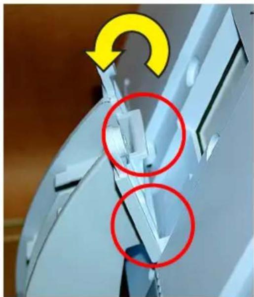
natural_image
Close-up of a mechanical component with highlighted circular features and a yellow curved arrow indicating rotation (no text or symbols)natural_image
Close-up of a white mechanical component with a red arrow pointing to a cable or wire connection (no visible text or symbols)natural_image
Close-up of a hand inserting a screw into a plastic housing component, with red arrows highlighting the ports (no text or symbols visible)natural_image
Close-up of a mechanical or electrical component with red arrows pointing to internal cable and connectors (no visible text or symbols)natural_image
Mechanical testing setup with a white panel and red arrow indicating compression or disassembly (no text or symbols visible)natural_image
Close-up of a hand holding a metallic mechanical component with a yellow circular arrow and green line indicating rotation (no text or symbols)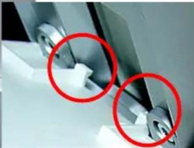
natural_image
Close-up of mechanical components with two red-circled annotations (no visible text or symbols)natural_image
Interior view of a cabinet with a red upward arrow on the ceiling (no text or symbols visible)Inbetriebnahme
MEMORY ALMOST FULL OK
| Temperatur | Feuchte | ||||||||||
| 20% | 30% | 35% | 40% | 45% | 50% | 55% | 60% | 65% | 70% | ||
| < 18° L | L | L | L | L | L | L | L | L | L | ||
| 18-19,9° L | L | L | K | K | K | K | K | K | L | ||
| 20-21,9° L | L | K | J | J | J | K | L | ||||
| 22-23,9° L | L | K | J | J | K | L | L | ||||
| 24-25,9° L | K | J | J | J | K | L | L | ||||
| 26-27,9° L | K | K | K | K | K | K | K | L | L | L | |
| über 28° L | L | L | L | L | L | L | L | L | L | L | |
- English edition 11/2011
Documentation © 2011 eQ-3 Ltd., Hong Kong
All rights reserved. No parts of this manual may be reproduced or processed in any form using electronic, mechanical or chemical processes in part or in full without the prior explicit written permission of the publisher.
It is quite possible that this manual has printing errors or defects. The details provided in this manual are checked regularly and corrections are done in the next edition. We do not assume any liability for technical or printing errors. All registered trade marks and copyrights are acknowledged.
Printed in Hong Kong.
We reserve the right to make changes due to technical advancements without prior notice.
83158 Y2011 V3.1
Table of contents
1 Information about these instructions....43
2 General information and function 43
3 Preparing for operation 47
3.1 Preparing the weather station....47
Connecting the power supply unit....47
Inserting batteries....48
Connecting to a PC....48
Standing up/Mounting the station 48
Start-up....51
4 Operation 52
4.1 Teaching-in/Deleting external sensors 52
4.2 Operation....54
4.3 Configuration 56
4.3.1 "SENSOR" menu, teaching-in/deleting sensors....56
4.3.2 "TIME/DATE" menu, setting the time and date....56
4.3.3 "UNITS" menu, setting the display units 57
4.3.4 "POSITION" menu, setting the position....58
4.3.5 "TIME ZONE" menu, setting the time zone 59
4.3.6 "LIGHTING" menu, setting the timings for the background light and controlling the brightness 59
4.3.7 "SYSTEM" menu, system settings....60
"BEEP", activating/deactivating the button tone....60
"DCF", activating/deactivating DCF-reception 60
"DST", activating/deactivating daylight saving adjustment....61
"INTERVAL", setting the data logger recording interval....61
"ALTITUDE", setting the height of the location above sea level....61
"RAIN CAL", entering the rain sensor adjustment value. 62
"SUN CAL", configuring the brightness threshold for hours of sunshine....62
"STORM WARNING", threshold for activating the storm warning....63
4.3.8 "CONNECTING MODE" menu 64
4.3.9 "CLEANING" menu, cleaning mode 64
4.3.10 "LIVE MODE" menu, calling the current weather data trend....64
4.3.11 „STATE" menu, display of memory state 65
4.4 Other functions and indicators....66
Moon phase indicator 66
Weather Joe....66
Weather forecast 66
Wind symbol indicator (wind sock) 66
Immediate indicator for the onset of rain....67
Comfort indicator....67
Trend indicator (history) 67
Data memory....67
Transmitting data to the combination sensor, "WAIT FOR TRANSMISSION"......67
Temperature trend indicator....67
Sensor status indicator....67
Radio controlled clock reception 68
Warning of extreme weather....68
Frost warning....68
General information about HomeMatic 68
Battery replacement 69
Notes on rectifying malfunctions 70
General information about radio operation....71
Notes on maintenance and care 71
Technical data 72
Connecting to a PC – Installing software 73
Appendix 74
Intended use, disclaimer of liability, safety instructions 75
WDC7000 menu overview 76
Table of coordinates for selected locations in Germany 77
1 Information about these instructions
Read these instructions carefully before beginning operation with your HomeMatic components.
Keep the instructions handy for later consultation!
Please hand over the operating manual as well when you hand over the device to other persons for use.

Attention! This indicates a hazard.

Note. This section contains additional important information!
2 General information and function
The touch screen wireless weather station WDC7000 is a high-quality, extremely user-friendly universal weather measuring system that can record, process and display data from up to 8 external wireless temperature and humidity sensors, as well as from a combination sensor, over a distance of up to 300 m (open air range).
The weather sensors for inside temperature, indoor humidity and barometric pressure are already built into the weather station, so no external sensors are required.
What is exceptional about this weather station is its operating concept. It does not rely on any conventional control elements; rather, it is operated solely via a touch-sensitive, large-format screen (touch screen) and simple menu structures. It is also very easy to teach-in the weather sensors. Weather data can be retrieved from the combination sensor in real time: simply tap the relevant display field to start the data retrieval process (bi-directional wireless technology). This enables you to always have up-to-date information at your fingertips. In “live mode”, the combination sensor can also be prompted to send its measured data at 2 second intervals for 20 seconds. In this way you can track the wind direction and velocity, for example, in real time for 20 seconds.
The display can be illuminated constantly or for a specific length of time so that it remains clearly visible in almost all lighting conditions. The glass base of the device and its transparent, cutting-edge surround are also illuminated.
An integrated radio controlled clock ensures that an accurate time is displayed and that data is recorded precisely.
The weather station is also ideally suited for long-term monitoring because of the large internal memory. A total of 3000 records can be stored in the integrated memory. These records can be read out on a PC (via a USB port), where they can be clearly analysed and visualised using the “WeatherPro Edition 2007” analysing software included in the scope of supply.

Please note!
The operating manual for the "WeatherPro Edition 2007" analysing software is not included in this operating manual. A separate operating manual for the software is supplied together with the software itself.
WDC7000 display and control options at a glance:
Display of inside temperature and humidity values
• Can be toggled to display the dew point
- Minimum and maximum temperatures saved, together with the time and date when they occurred
- Minimum and maximum humidity values saved, together with the time and date when they occurred
• Comfort zone indicator
• Trend indicator for the last 24 hours, displayed in graphic format
Display of values for one of 9 (max.) sensors
- Can be toggled to display the dew point or the wind chill temperature
- Minimum and maximum temperatures saved, together with the time and date when they occurred
- Minimum and maximum humidity values saved, together with the time and date when they occurred
• Trend indicator for the last 24 hours, displayed in graphic format - Frost warning
Display of wind velocity, together with wind direction and fluctuation range
• Units that can be selected: km/h, m/s, mph
• Maximum wind strength value saved, together with the time and date
• Wind direction indicator with fluctuation range as a wind rose and in ni
• Wind sock symbol to clearly indicate different wind strengths
Display of rainfall in mm, inches or l/m2 for:
- Total rainfall since last reset/for last hour/current hour/last 24 h/current 24 h (hourly values recorded at 30 minutes past the hour; daily values at 07:30 on the day in question)
• Maximum volume per hour and per day saved
• Additional (immediate) indicator for the onset of rain
Display of barometric pressure trend indicator:
• Trend indicator for the last 24 hours, displayed in graphic format
- Barometric pressure trend indicator with 5 levels: increasing sharply, increasing, constant, falling, falling sharply
Weather forecast symbol indicator: rainy, cloudy, bright, sunny
"Weather Joe" weather indicator
A great feature of the WDC7000 is "Weather Joe", who is based on the all but forgotten idea of the "weather house", where a figure with an umbrella would come out
of the door when the weather was poor and one wearing more summery clothing would appear when the weather was good.
The figure's behaviour depends on several weather factors, so you can see at a glance what would be appropriate outdoor clothing at that particular time. Not only are the current measured values for the outside temperature, humidity, wind and rain analysed, but weather forecasting also plays a significant role. This means that "Weather Joe" is displayed in many different ways and wearing a variety of different clothes, depending on the weather conditions outside your door.
You can find a precise description of the relevant analysis criteria in Subsection 4.4 of this operating manual.
Display of time and date
- Integrated DCF-77-clock with manual adjustment option, daylight saving adjustment can be deactivated
Display of sunrise and sunset times
- Based on the individual location data entered, can be calculated in the latitude range -60^ to +60^ N
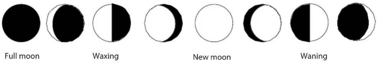
Moon phase indicator
- Displays the current moon phase: new moon, waxing moon, full moon, waning moon
Display of hours of sunshine (total or current day)
- Minimum and maximum hours per day saved, together with the time and date when they occurred
- Sun symbol when the sun is shining
Data logger function
- The data logger collects up to 3000 records at adjustable intervals; the records can then be read out using the "WeatherPro Edition 2007" analysing software via a USB interface.
- When the data logger memory is almost full, a prompt to read out the data appears in good time.
Other information
- Really easy "context-sensitive" operation using clear menu structures
- A beep confirming that an operation has been performed can be activated and deactivated
- Can either be stood up as a desktop device or mounted on a wall
- ON time for the display light can be programmed

All important weather data is shown on the display at the same time, so you do not have to do anything to the device in order to ascertain current weather conditions. Several base units can be operated in parallel, allowing data from sensors at various different locations to be displayed simultaneously.
The external sensor system of the WDC7000 uses wireless data transmission only. This means that you can stand or mount the sensors up to 300 m (depending on local conditions, see the "Range" section) away from the base station.
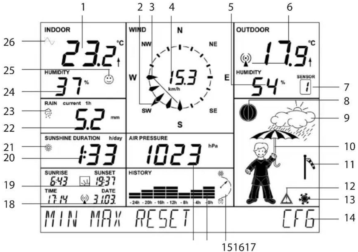
Quick overview of the display fields
text_image
INDOOR 23.2 °C HUMIDITY 37 % RAIN current 1h 5.2 mm SUNSHINE DURATION h/day :33 SUNRISE SUNSET 6:43 19:37 TIME DATE 17:4 3:03. MIN MAX RESET WIND N NE NW 15.3 km/h SW SE S AIR PRESSURE hPa 1023 HISTORY -24h -20h -16h -12h -8h -4h -0h OUTDOOR 17.9 °C HUMIDITY SENSOR 54 % I 7 8 9 10 11 12 13 14 151617 CFG- Current inside temperature and temperature trend
- Current wind direction indicator (main wind direction)
- Fluctuation range indicator if wind is not constant
- Wind velocity indicator
- Current humidity of the selected outdoor sensor
- Current temperature of the selected outdoor sensor with temperature trend and reception indicator
- Indicates the currently selected outdoor sensor (if the HM-WDS100-C6-O (OC3) combi-sensor is selected, nothing is displayed here)
- Moon phase indicator
- Weather forecast indicator (sunny, bright, cloudy, rainy)
- Animated "Weather Joe" multifunctional weather indicator
- Wind velocity indicator (light, moderate, strong)
- Warning of extreme weather
- Frost warning
- Menu bar
- Barometric pressure trend indicator: increasing sharply, increasing slowly, constant, falling slowly, falling sharply; for a more detailed explanation, refer to the definitions of terms
- History indicator, relating to the current value (refer also to 26)
- Current barometric pressure indicator
- Time and date indicator, reception indicator in the case of DCF-77-reception
- Indicates sunrise and sunset times
- Hours of sunshine indicator
- Sun symbol when the sun is currently shining, otherwise a cloud symbol is displayed here
- Rainfall indicator
- Indicator for the onset of rain
- Current indoor humidity
- Comfort zone indicator shows a pleasant/unpleasant climate
- Symbol appears in the field for the weather factor currently activated for the history indicator (inside or outside temperature); if the symbol does not appear in either field, the barometric pressure history is currently being displayed.
3 Preparing for operation
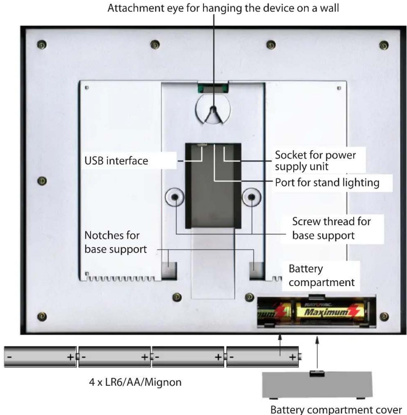
The weather station is operated via the power supply unit supplied with the product. Four Mignon cell batteries 1.5 V, alkaline type LR6 are used for standby operation. However, in this case only certain functions of the weather station will be available. The photo below shows the rear of the station with the battery compartment, correct battery polarity, base support mounting points and hanging point.
text_image
Attachment eye for hanging the device on a wall USB interface Socket for power supply unit Port for stand lighting Notches for base support Screw thread for base support Battery compartment 4 x LR6/AA/Mignon Battery compartment coverConnecting the power supply unit
First insert the round DC-plug of the power supply unit supplied with the product into the corresponding socket on the rear of the device, then plug the power supply unit into a 230 V main socket. If any batteries have been inserted into the battery compartment, this will deactivate them.
Inserting batteries
Remove the battery compartment cover and insert four Mignon cells, 1.5 V, alkaline type LR6 into the battery compartment, observing the correct polarity as per the corresponding diagram. Reclose the battery compartment.
Connecting to a PC
If the station is to be connected to a PC, connect the supplied USB cable featuring a mini USB socket to the USB interface on the WDC7000. Connect the other end of the cable to a USB interface on the PC (refer also to Section 10).
Standing up/Mounting the station
The weather station can either be mounted on a vertical surface (wall) using the attachment eye or stood on an even horizontal surface using the tabletop stand. The tabletop stand is mounted as follows, with the help of the hexagon socket screws and hexagon wrench supplied:
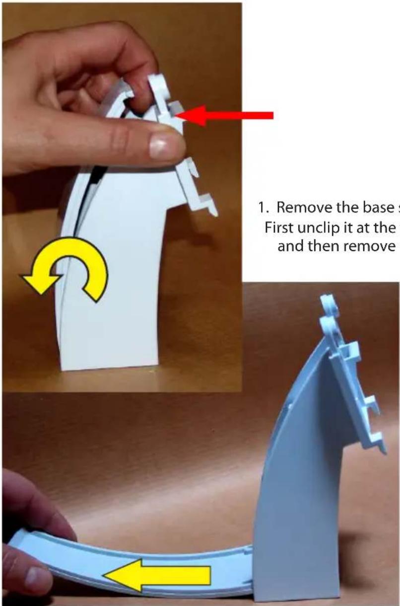
text_image
1. Remove the base s First unclip it at the and then remove1. Remove the base support cover:
First unclip it at the top, ease it all the way down and then remove it.
natural_image
Close-up of a white electronic device with exposed internal components and a red circle highlighting a cable, being held by fingers (no text or symbols visible)- Latch the base support onto the clip on the glass base and sit it down on the two screw domes.
natural_image
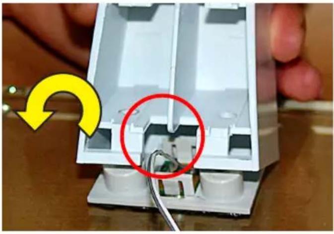
Close-up of a white plastic electrical connector with two metal pins and a hand adjusting it (no text or symbols visible)- Use the hexagon wrench and two hexagon socket screws supplied to screw the base support onto the glass base. When doing this, make sure that the lighting cable from the device base is routed to the side as shown in the photo, so it does not become pinched.
natural_image
Close-up of a white mechanical component with a red arrow pointing to a section, no visible text or symbols.
natural_image
Close-up of a mechanical component with two red-circled features and a yellow curved arrow indicating rotation (no text or symbols)- Attach the weather station to the clips on the base support and swivel it onto the base support until the screw domes sit properly in the corresponding receptacles on the weather station.
Caution!
Do not let go of the weather station until the two hexagon socket screws have been inserted (see the next step). When holding the weather station, do not touch the display. Only hold the weather station by its surround.
natural_image
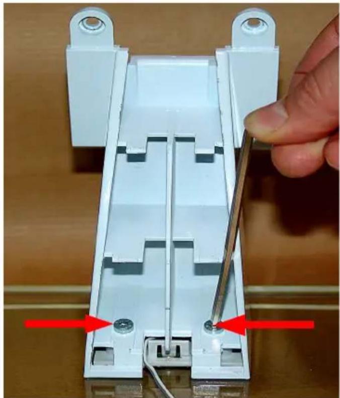
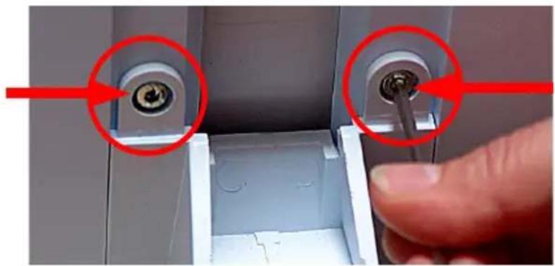
Close-up of a hand inserting a screw into a plastic housing component, with red arrows highlighting the ports (no text or symbols visible)- Use the hexagon wrench and two hexagon socket screws supplied to screw the base support onto the weather station.
natural_image
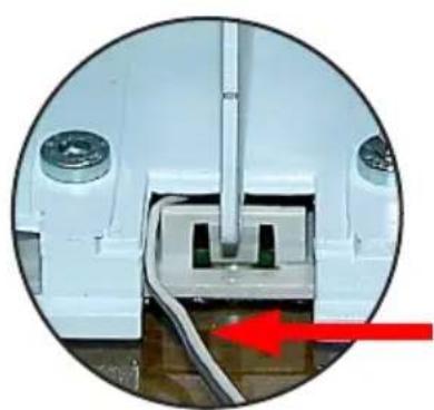
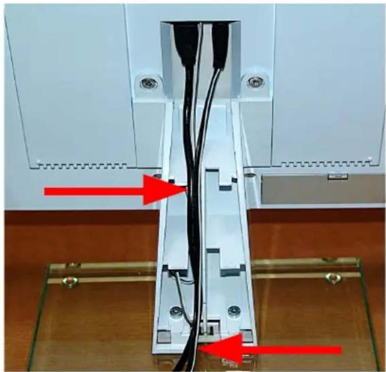
Close-up of a mechanical or electrical component with red arrows pointing to internal channels and connectors (no visible text or symbols)- This is how the cables are connected, laid and routed in the base support. Make sure that the cables really do lie in the middle as shown; otherwise, they may prevent the cover from being latched on later.
Caution!
The lighting cable for the stand and the USB cable can only be inserted in one direction. Do not use force to insert them!
Surplus lighting cable can be stored in a chamber within the support.
natural_image
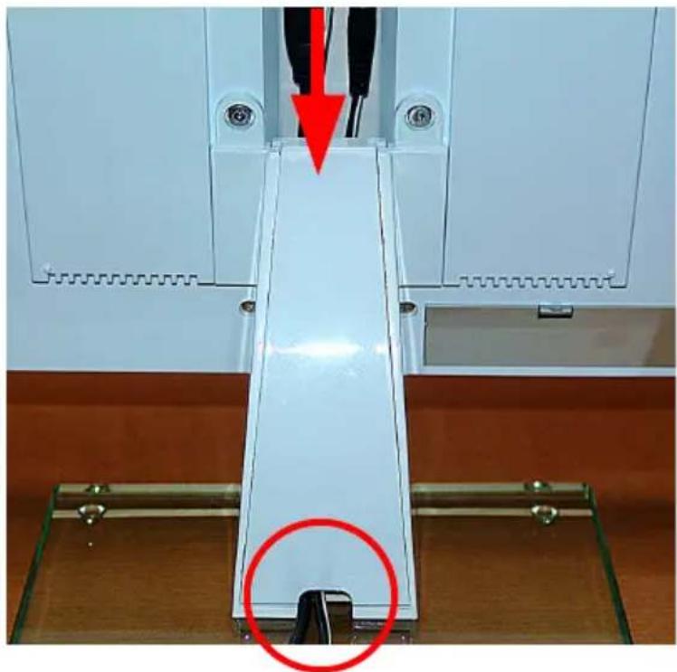
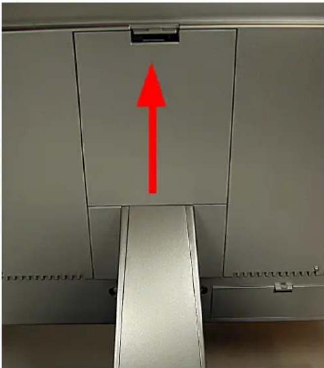
Close-up of a white mechanical device with a red arrow pointing to a component, and a red circle highlighting a specific area (no text or symbols visible)- Now attach the cover to the base support:
lay the cover flat and insert it into the receptacles on the support (refer also to 1), ease it up and latch it in at the top.
Caution!
There must not be any resistance when you ease the cover up; if there is, either the cover is not inserted properly at the bottom or the cables are not lying in the duct. You must be able to see the cables protruding properly from the bottom.
natural_image
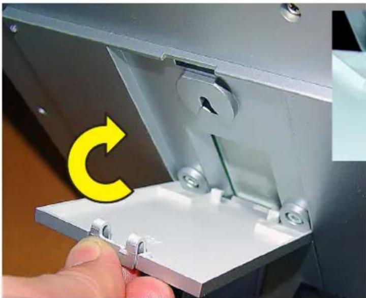
Close-up of a hand holding a metallic mechanical component with a yellow circular arrow and green line indicating rotation (no text or symbols)
natural_image
Close-up of mechanical components with two red-circled annotations (no visible text or symbols)- Finally, insert the clips on the cover into the corresponding notches on the cable channel (see detail photo above), swivel it upwards and latch it in at the top (see photo below).
natural_image
Interior view of a cabinet with a red upward arrow on the ceiling (no text or symbols visible)Start-up
- Once the power supply unit has been connected, all the segments on the display will be tested briefly (all segments displayed).
- A short beep will then be heard and the version numbers of the weather station will appear on the display.
- Next, the inside temperature and humidity values are displayed, along with the barometric pressure. The corresponding sensors are built into the base station.
- The external sensors now have to be started up.
4 Operation
Once the wireless sensors have been installed and the base unit has been started up, data from the wireless sensors does not immediately appear on the base unit's display. As every sensor has an individual serial number, each one must be registered with the base unit separately.
The advantage of this approach is that data is only recorded from sensors that have been specifically registered, not from any sensors belonging to a different, neighbouring system, for example, not even after a restart.

Please note!
If no input area of the menu line is touched for around 5 s when making entries, the device returns to the main menu automatically (and incorporates/ saves any settings that have been made). Therefore, once you have made an entry, wait until the main menu appears again. In the same way, you can also exit a menu each time you have made an adjustment. Just touch the relevant input areas lightly, do not press down on them hard. Do not use objects to press or tap the display. Once inside a menu, touching and keeping your finger on an adjustment area allows you to adjust values faster, as the system will continue to scroll through the possible options without you having to keep touching the adjustment area over and over again.
4.1 Teaching-in/Deleting external sensors
A maximum of nine BidCoS ^TM -compatible external sensors can be registered with the system.
Memory slots 1 to 8 are reserved for the sensors HM-WDS40-TH-I (IT), HM-WDS30-T-O (ITC), and HM-WDS10-TH-O (OTH) sensors.
Memory slot 9 is reserved for the HM-WDS100-C6-O combination sensor.
If there are several sensors of the WDS10, WDS30, or WDS40 types, we recommend that the batteries are first removed from all sensors in order to ensure the sensors are assigned uniquely.
Teaching-in
- Touch "CFG" in the menu line.
- The following appears:
NEXT CLEANING
ENTER
- Touch "NEXT" and the following appears:
NEXT SENSOR
ENTER
- Touch "ENTER" and the following appears:
SENSOR NO 1 ADD DEL
- Touch "SENSOR" repeatedly to select the memory slot where the desired sensor is to be saved. Please note that the HM-WDS100-C6-O can only be saved to the "COMBI-SENSOR" memory slot.
- Then select "ADD" and the following appears (example for sensor 1):
SENSOR NO 1 -- SYNC ADD DEL
- The desired sensor now needs to be taught-in. To do this, insert the batteries in the corresponding sensor and press its teach-in button. If "USED" appears in under one second, the sensor has been taught-in correctly.
Data from the HM-WDS100-C6-O appears automatically (after a maximum of 6 minutes) in the corresponding areas of the display; data from the other sensors appears as per the memory slot selected in the "OUTDOOR" display field ("Sensor" field).
Identification of assigned memory slots
Memory slots that have already been assigned are identified by "USED" after the memory slot number.
However, this label does not indicate whether the corresponding sensor is actually active or not. This will only become apparent if no data is provided or out-of-date information is supplied when the sensor is selected and the reception indicator in the "OUTDOOR" field is active.
Deleting a sensor's assignment
If necessary, a sensor's serial number can be deleted from the sensor memory.
- First proceed as described under "Teaching-in", then select the desired sensor and, instead of touching "ADD", touch the "DEL" option.
- "USED" is deleted from after the sensor number, making the memory slot available for registering a different sensor.

Tip for starting up sensors
In order to start sensors up properly, they can first be activated in the vicinity of the weather station.
However, there must be at least 1 m between the sensor and the weather station in order to prevent malfunctions.
4.2 Operation
As all relevant data appears on the display at the same time, operation is essentially restricted to simply selecting other sensors or additional weather data by lightly touching the corresponding display field.
The display is divided into the display field and the menu line (device main menu displayed):
MIN
MAX
RESET
In normal mode the following functions can be accessed by touching the corresponding fields on the display:
INDOOR: Toggle between displaying the temperature and the dew point ("DEWPOINT")
OUTDOOR: Toggle between displaying the temperature, the dew point and the wind chill temperature
HUMIDITY: No function
SENSOR: Toggle between the external sensors:
1...8: HM-WDS10-TH-O, HM-WDS30-T-O or
HM-WDS40-TH -1
No display: HM-WDS100-C6-O
RAIN: Toggle between the total rainfall since the last reset ("total"), rainfall for the current hour ("current 1h"), the last hour ("1h"), the current day ("current 24h") and the previous day ("24h"); hourly values recorded at 30 minutes past the hour; daily values at 07:30 on the day in question
SUNSHINE DURATION: Toggle between hours of sunshine for the current day ("h/day") and the total hours of sunshine since the last reset ("h")
TIME/DATE: No function
WIND: Toggle the numerical display between wind velocity in km/h, m/s, mph and wind direction in degrees
AIR PRESSURE: Toggle the display of barometric pressure between the pressure measured at the location ("absolute") and the pressure at sea level calculated from that measured value ("relative")
HISTORY: Toggle the trend indicator for the last 24 hours between the barometric pressure, inside temperature and outside temperature (of the sensor shown); refer also to point 26 on page 46
WEATHER SYMBOL FIELD: No function
Main menu functions
MIN: Call minimum values
When “MIN” is touched, the minimum values for each type of data are shown in the corresponding display fields. Touch the relevant field (temperature, humidity, etc.) and the time stamp (date, time) of when the minimum value occurred is shown at the right of the menu line.
Touch "MIN" again to return to the main menu and reinstate the standard display of data.
MAX: Call maximum values
When “MAX” is touched, the maximum values for each type of data are shown in the corresponding display fields. Touch the relevant field (temperature, humidity, etc.) and the time stamp (date, time) of when the maximum value occurred is shown at the right of the menu line.
Touch "MAX" again to return to the main menu and reinstate the standard display of data.
RESET: Reset certain values
This menu has three submenus for resetting the total hours of sunshine ("SUN"), the rainfall ("RAIN") or the MIN-MAX memory ("MIN-MAX"):
Touch "RESET". The first RESET menu appears:
RESET
RAIN
Touch "RESET" on the left repeatedly to select the required option and then touch "OK". The corresponding data is now deleted and the main menu and standard display of data are reinstated automatically.
However, if you do not want to delete any data, wait until the device returns to the main menu. In this case, no data is deleted.
CFG: Call the configuration menu
4.3 Configuration
The weather station is supplied in a condition where its basic functions are ready for operation immediately after start-up, with no need for any other settings to be made (basic functions do not include the moon phase indicator, display of sunrise and sunset times, date, time or min./max. indicator).
Some configuration settings do need to be made to enable you to use the additional and time-specific functions.
- Touch "CFG" to open the configuration menu.
- Touch "NEXT" repeatedly to move through the main menu items of the configuration menu. The Appendix contains a menu overview to make it easier for you to find specific menus.
4.3.1 "SENSOR" menu, teaching-in/deleting sensors
Refer to 3.1
4.3.2 "TIME/DATE" menu, setting the time and date
This setting is only required if DCF-synchronisation has not been performed.
- Select the "TIME/DATE" menu:
NEXT TIME/DATE ENTER
- Touch "ENTER" and the following appears:
TIME 24H
- Touch "24H" to toggle between a 12-hour and a 24-hour clock display.
- Touch "TIME" and the following appears:
YEAR + 2006 -
- Touch "+" or "-" to set the year.
- Touch "YEAR" and the following appears:
MONTH +07 -
- Touch "+" or "-" to set the month.
- Touch "MONTH" and the following appears:
DAY +01 -
- Touch "+" or "-" to set the day of the month.
- Touch "DAY" and the following appears:
WEEKDAY
+ MON
- Touch "+" or "-" to set the day of the week.
- Touch "WEEKDAY" and the following appears:
HOUR +01 -
- Touch "+" or "-" to set the hour.
- Touch "HOUR" and the following appears:
MINUTE +01 -
- Touch "+" or "-" to set the minute.
- Wait for a few seconds. The time and date will then appear on the display, along with the sunrise and sunset times for the factory-set location (52.5/13.4 degrees, Berlin) and the current moon phase.
4.3.3 "UNITS" menu, setting the display units
- Select the "UNITS" menu:
NEXT UNITS ENTER
- Touch "ENTER" and the following appears:
TEMPERATURE
DEG C
- Touch "DEG" to toggle between displaying temperature values in degrees Celsius (C) and Fahrenheit (F).
- Touch "TEMPERATURE" and the following appears:
PRESSURE
HPA
- Touch "HPA" to toggle between displaying barometric pressure values in hPa (HPA), mmHg (MMHG) and inHg (INHG).
- Touch "PRESSURE" and the following appears:
RAIN MM
- Touch "MM" to toggle between displaying rainfall values in mm (MM), inches (INCH) and l/m2 (L/M2).
- Wait for a few seconds. The data will then appear on the display in the units you have just set.
4.3.4 "POSITION" menu, setting the position
Position data for the location of the weather station is required in order to calculate the sunrise and sunset times. Latitudes can be entered in the range -60.0^ to +60.0^ . You can determine your position in various ways:
- The Appendix contains a table listing the coordinates of many German cities. You can use it to select a location nearby and enter the appropriate coordinates.
- If you have access to an in-car or a mobile GPS navigation device, for example, you can use that to check your position data; this will give you your precise location.
- You can also find precise coordinates on the Internet, as there are many sites to do with navigation.
- Select the "POSITION" menu:
NEXT POSITION ENTER
- Touch "ENTER" and the following appears:
LATITUDE + 52.4
- Touch "+" or "-" to set the latitude.
- Touch "LATITUDE" and the following appears:
LONGITUDE +007.8 -
- Touch "+" or "-" to set the longitude.
- Wait for a few seconds. The adjusted sunrise and sunset times will then appear on the display.

Please note that the sunrise and sunset times will only be strictly accurate at the coast or for a location with a completely flat landscape. In practice, mountains, forests of very tall trees, etc. can considerably shorten daylight hours.
The times specified may even be a few minutes out if the location is an ideal one, as an approximate formula is used in the calculation.
4.3.5 "TIME ZONE" menu, setting the time zone
The time zone needs to be specified in order to calculate the sunrise and sunset times. The current time difference from UTC (Coordinated Universal Time) must be entered.
The following values apply for Germany:
Daylight saving time ☒+2
Winter time ☒+1
- Select the "TIME ZONE" menu:
NEXT TIMEZONE ENTER
- Touch "ENTER" and the following appears:
TIMEZONE
+ 01
- Touch "+" or "-" to set the longitude.
- Wait for a few seconds. The adjusted sunrise and sunset times will then appear on the display.
4.3.6 "LIGHTING" menu, setting the timings for the background light and controlling the brightness
You can use this menu to set the ON time for the background light, which turns on automatically when the screen is touched and turns off automatically after a certain (adjustable) length of time. The light can be set to "OFF" (light never comes on), to a time of between 5 s and 10 m or to continuous (ON). Furthermore, the times during which the light should be on continuously can be set.
Automatic adjustment to the ambient brightness can also be activated/deactivated so that the display can be easily read in practically all brightness conditions.
The background light is only functional during mains operation.
- Select the "LIGHTING" menu:
NEXT LIGHTING ENTER
- Touch "ENTER" and the following appears:
LIGHTING + 10 SEC -
- Touch "+" or "-" to set the ON time.
- Touch "LIGHTING" and the following appears:
BRIGHT CTRL ON
- Touch "ON" to toggle between activating (ON) and deactivating (OFF) automatic lighting control.
- Touch "BRIGHT CTRL" and the following appears:
BEGIN
+16.00-
- Touch "+" or "-" to set the switch-on time for the (continuous) light.
- Touch "BEGIN" and the following appears:
END
+23.45-
- Touch "+" or "-" to set the switch-off time for the (continuous) light.
- Wait for a few seconds. The device will then return to normal mode and the data that has just been set will become active.
4.3.7 "SYSTEM" menu, system settings
You can use this menu to make settings for the automatic daylight saving adjustment (DST, refer also to the Appendix), for activating the button tone (BEEP), for activating the radio controlled clock (DCF), for the data logger recording interval (INTERVAL), for the location height (ALTITUDE), for adjusting the rain sensor (RAIN CAL) and for configuring the brightness threshold for hours of sunshine (SUN CAL).
Activating/Deactivating the button tone
- Select the "SYSTEM" menu:
NEXT
SYSTEM
ENTER
- Touch "ENTER" and the following appears:
BEEP
ON
- Touch "ON" to toggle between activating (ON) and deactivating (OFF) the button tone.
Activating/Deactivating DCF-reception
- Select the "SYSTEM" menu then the "DCF" option (via BEEP) and the following appears:
DCF
OFF
- Touch "ON" to toggle between activating (ON) and deactivating (OFF) DCF-reception.
Activating/Deactivating daylight saving adjustment
- Select the "SYSTEM" menu then the DST option (via BEEP and DCF) and the following appears:
DST
ON
- Touch "ON" to toggle between activating (ON) and deactivating (OFF) automatic daylight saving adjustment.
Setting the data logger recording interval
The data logger recording interval defines the intervals at which the integrated data logger is to log records. The shorter the selected intervals, the shorter the recording time, which results in more detailed records. The longer the intervals, the longer the possible recording time, which results in a lower resolution for the weather data. The recording interval can also be set from the PC.
- Select the "SYSTEM" menu then the "INTERVAL" option (via BEEP, DCF and DST) and the following appears:
INTERVALL
ENTER
- Touch "ENTER" and the following appears:
INTERVALL
+ 05
- Touch "+" or "-" to set the interval time (OFF [data logger off] or between 5 and 60 minutes). Below are a few examples of how the interval time and recording time relate to one another.
Interval time Max. recording time
| OFF | no recording |
| 5 minutes | 10.4 days (250 hours) |
| 10 minutes | 20.8 days (500 hours) |
| 30 minutes | 62.5 days (1500 hours) |
| 60 minutes | 125 days (3000 hours) |
"ALTITUDE", setting the height of the location above sea level
The location height is used to calculate the relative barometric pressure at sea level compared to the absolute barometric pressure at the location. This relative value is an important reference variable that is needed to correctly interpret weather reports that are based on the relative barometric pressure.
- Select the "SYSTEM" menu then the "ALTITUDE" option (via BEEP, DCF, DST and INTERVAL) and the following appears:
ALTITUDE
ENTER
- Touch "ENTER" and the following appears:
ALTITUDE
+
0000
- Touch "+" or "-" to set the geographical height of the location above sea level in metres.
- Wait for a few seconds. The adjusted data for the relative barometric pressure will then appear on the display.
Alternatively, the value can also be entered via the PC program.
"RAIN CAL", entering the rain sensor adjustment value
The rainfall measuring system is factory-set to a high degree of accuracy, so it does not usually need to be adjusted.
The adjustment value must first be calculated in normal mode, as described in the section titled "Adjusting the rainfall measuring sensor".
- Select the "SYSTEM" menu then the "RAIN CAL" option (via BEEP, DCF, DST, INTERVAL and ALTITUDE) and the following appears:
RAIN CAL
ENTER
- Touch "ENTER" and the following appears:
RAIN CAL + 295 -
- Touch "+" or "-" to set the previously calculated value.
- Wait for a few seconds. The device will then return to normal mode.
Alternatively, the value can also be entered via the PC program.
"SUN CAL", configuring the brightness threshold for hours of sunshine
The WDC7000 weather station works in conjunction with the WDS100-C6-O combination sensor to determine the hours of sunshine. The threshold value is set on the base station and transmitted to the combination sensor. This sensor then evaluates the data:
Brightness received at sensor greater than threshold value ☒ sun shining
Brightness received at sensor lower than threshold value ☒ sun not shining
The user can set the brightness threshold on an individual basis in order to adapt the sensor to local conditions. The threshold value should be defined as when the sun comes up or goes down so that the current brightness value can be used to calculate the threshold.
Example: After sunrise the brightness value is 131, for example. This means that the threshold value should be set to 131 so that the hours of sunshine start to be counted from that point.
- Select the "SYSTEM" menu then the "SUN CAL" option (via BEEP, DCF, DST, INTERVAL, ALTITUDE and RAIN CAL) and the following appears:
SUN CAL ENTER
- Touch "ENTER" and the following appears:
SUN CAL 131 + 085 -
Decrease threshold
Threshold currently set
Increase threshold
Current brightness value1
- Touch "+" or "-" to set the threshold value. The setting range runs from 0 to 255.
- Wait for a few seconds. The device will then return to normal mode.
^1 It is not possible to directly convert this value into the lux unit of luminance.
„STORM WARNING“, threshold for activating the storm warning
The storm warning is activated if the air pressure drops by a predefined value (or more) within one hour. The minimum value is specified in hPa (Hectopascals) and can be configured as follows:
- Select the „SYSTEM“ menu then the „STORM WARNING“ option (via BEEP, DCF, DST, INTERVAL, ALTITUDE, RAIN CAL and SUN CAL) and the following appears:
STORM WARNING ENTER
- Touch „ENTER“ and the following appears:
STORM WARNING 5 HPA
- Touch the „HPA“ buttons to reduce the value or touch the numbers to increase the threshold.
4.3.8 "CONNECTING MODE" menu
In connecting mode you can teach-in the internal sensors of the WDC7000 to other WDC7000 stations and to the HomeMatic central control unit. To do this, you must set the corresponding connection partners and the WDC7000 to teach-in mode.
CONNECTING
MODE
OK
- To launch teach-in mode touch "OK" and the following appears:
CONNECTING
The WDC7000 is now in teach-in mode. Once the teach-in procedure has been completed successfully, teach-in mode and the configuration menu are exited. If no teaching-in is performed for 20 seconds, teach-in mode and the configuration menu are exited.
4.3.9 "CLEANING" menu, cleaning mode
As the display is touched on a regular basis this can make it dirty, so it must be wiped with a dry linen cloth from time to time (a cleaning cloth for spectacles is ideally suited to this task; do not use any cleaning fluids as this could damage the display). To ensure that you do not change any settings on the station when wiping the display, you can use cleaning mode, which locks all touch fields for 20 seconds.
- Select the "CLEANING" menu:
NEXT CLEANING
ENTER
- Touch "ENTER" and the following appears:
CLEANING
START
- Touch "START" and the following appears:
CLEANING
WAIT
- You can now clean the display. After 20 s the normal display will reappear.
4.3.10 "LIVE MODE" menu, calling the current weather data trend
In this mode, you can touch an additional field to prompt the combination sensor to send its measured data at 1 second intervals for 10 seconds. So a single touch is all that is needed to
obtain the very latest weather data, enabling you to track the wind direction and wind velocity trend, for example, for 10 seconds.
As the combination sensor switches to receive data more often when "LIVE MODE" is active, it consumes more current, which has an adverse effect on battery life. Therefore, the "LIVE MODE" menu can be used to set a period of time for which "LIVE MODE" will remain active. During this period the main menu line will also display the "REQ" touch field, which is used to request the live retrieval of data described above.
- Select the "LIVE MODE" menu:
NEXT LIVE MODE ENTER
- Touch "ENTER" and the following appears:
BEGIN +16.00-
- Touch "+" or "-" to set the switch-on time for "LIVE MODE".
- Touch "BEGIN" and the following appears:
END +23.45-
- Touch "+" or "-" to set the switch-off time for "LIVE MODE".
- Wait for a few seconds. The device will then return to normal mode and the data that has just been set will become active.
- The menu line indicates that data is being transmitted to the combination sensor with the message: "WAIT FOR TRANSMISSION". The weather station cannot be operated for as long as this message is displayed.
- When "LIVE MODE" is active, the menu also displays the "REQ" touch field for retrieving data:
MIN MAX RESET
REQ CFG
4.3.11 „STATE“ menu, display of memory state
The utilisation of the internal data memory can be displayed in this menu. The value that is displayed represents the amount of memory usage in percent.
- Select the „STATE“ menu:
NEXT STATE ENTER
- Touch „ENTER“ and the following appears:
MEMORY USAGE 050
- The displayed values show the amount of memory usage in percent (e.g. 50%, see above).
4.4. Other functions and indicators
Moon phase indicator
The moon phase indicator uses the following symbols:
Weather Joe
Weather Joe is an animated figure that provides information on several weather factors at the same time:
Outside temperature (combination sensor only)
- Weather Joe's clothing is based on the outside temperature detected at the combination sensor.
Rain
- If the forecast function has detected rainy weather, the figure carries a closed umbrella.
- At the onset of rain, the figure carries an open umbrella.
Wind velocity
- At wind velocities above 20 km/h (moderate wind), Weather Joe's hair is blown about. If the temperature is also below 14°C, the scarf he is wearing is blown by the wind too.
Weather forecast
- The weather forecast symbols indicate the following forecasts:
Cloud and rain
Rainy
Cloud
Cloudy
Cloud and sun
区
Bright
Sun
Sunny
Wind symbol indicator (wind sock)
- The wind sock symbol in the forecast display field allows you to see at a glance if the wind is currently light, moderate or strong:
Wind sock hanging down
☒ Light wind (<10 km/h)
Wind sock half raised
☒ Moderate wind (10...20 km/h)
Immediate indicator for the onset of rain
- When the onset of rain is detected, this is reported to the base station the next time data is wirelessly transmitted and is indicated by a rain cloud in the "RAIN" field and Weather Joe's open umbrella.
Comfort indicator
- The comfort indicator (LKJ) reflects the interior climate (the temperature related to the humidity). A table of values for the display ranges can be found in the Appendix.
Trend indicator (history)
- The bar graph shows the barometric pressure, outside temperature or inside temperature trend over the last 24 hours. The individual columns do not represent absolute values; rather, they show the difference to the current measured value (0 h column). This reference point is always of a medium height (4 bars) so that the trend can be identified immediately.
Data memory
- If the data memory is almost full, the following message will appear in the menu line:
MEMORY ALMOST FULL OK
- Touch this input area to acknowledge it and read the collected data out via the PC.
Transmitting data to the combination sensor, "WAIT FOR TRANSMISSION"
- If "WAIT FOR TRANSMISSION" appears in the menu line, the weather station is transmitting data to the combination sensor, activating live mode or sending configuration data relating to hours of sunshine, for example.
This procedure can take a few minutes, during which time the weather station cannot be operated.
Temperature trend indicator
- An arrow indicating the trend will appear to the right of the temperature data in the "Indoor" and "Outdoor" display fields if the temperature has increased (arrow pointing up) or decreased (arrow pointing down) during the latest transmission interval.
Sensor status indicator
- In the outdoor sensor display field ("Outdoor"), a small reception indicator shows the status of the sensor:
Reception indicator displayed constantly ☒ Sensor is being received
correctly
Reception indicator flashing ☒ Sensor has not been received
for 40 minutes
No reception indicator displayed ☒ Sensor not available, permanently
damaged or faulty
Radio controlled clock reception
- Immediately after switch-on, the weather station attempts to receive the DCF-77 time signal in order to set the clock automatically.
- If the weather station receives the time signal, the time and date are updated automatically and a small reception indicator appears between the two items of data.
- The weather station attempts to synchronise with the DCF-77 transmitter every day at 04:00.
- If DCF-77-reception is not possible, the internal clock operates as a quartz clock.
- DCF-77-reception can be deactivated if necessary (refer to the "SYSTEM/DCF" menu).
Warning of extreme weather
- A warning symbol appears in the weather forecast display field if the barometric pressure falls sharply over a short period of time. This points to a potential gale or a storm brewing, for example.
Frost warning
- A snowflake symbol appears in the weather forecast display field if the temperature measured at the combination sensor falls below 4^ C.
5 General system information about HomeMatic
This device is a part of the HomeMatic home control system and works with the bi-directional BidCoSTM wireless protocol.
All devices are delivered in a standard configuration. The functionality of the device can also be configured with a programming device and software.
The additional functions that can be made available in this way and the supplementary functions provided by the HomeMatic system when it is combined with other components are described in the separate Configuration Instructions and in the HomeMatic System Manual.
All current technical documents and updates are provided at www.HomeMatic.com.
6 Battery replacement
Base station
If the symbol indicating that a battery is empty (i) appears on the display, all batteries need to be replaced with others of the same type as per Subsection 2.1. Always replace all 4 batteries and use only high-quality alkaline batteries. Always leave the power supply unit connected when replacing the batteries in order to avoid losing any data.

Please note!
If no power supply unit is connected, the data memory will be deleted when the batteries are replaced.
Wireless sensors
The batteries in these sensors have a service life of up to 2 years (alkaline batteries). If the symbol indicating that a battery is empty (appears in the "OUTDOOR" sensor field when the corresponding sensor is selected, the batteries need to be replaced.
Caution! Danger of explosion if battery is replaced improperly.
Used batteries are not to be disposed of with the household waste! Please dispose them at your local battery collection point!

7 Notes on rectifying malfunctions
Possible malfunctions that could prevent transmitted measured values being displayed properly:
No reception – The distance between the transmitter and the receiver is too long or too short (<1 m).
Decrease/increase the distance between the transmitter and the receiver.
No reception – Materials with good shielding properties are located between the transmitter and the receiver (thick walls, reinforced concrete, etc.).
Find another position for the transmitter or the receiver. Refer also to Section 6 ("Range").
No reception – Transmitter batteries are empty.
Replace the batteries.
No reception – The transmitter is subject to a source of interference.
(Wireless device, radio headphones/loudspeaker)
Eliminate the source of interference or find another position for the transmitter or the receiver. Often the interference is only present on a temporary basis (radio telephony) or can be eliminated very easily. If radio headphones, wireless baby monitors or other similar devices are operated at 868 MHz in your home or in the neighbourhood, for example, they are usually only switched on for a limited period of time. The majority of these devices can be moved to an interference-free frequency and a measure such as this can mask interference really effectively.
Wireless sensor interferes with other devices in the 868 MHz band
Transmissions from the wireless outdoor sensor can interfere temporarily (every 2 to 3 min for around 100 ms) with other devices working on the same channel.
Additional notes on start-up and the rectification of malfunctions
Rotate the weather station a little if necessary or, if reception is poor, position it far away from electric motors, electrical machinery, television sets, computer monitors
and large metal surfaces.
To make start-up easier you can initially position the sensors in the vicinity of the base unit (but at least 1 m away from it). This enables you to check that the sensor is transmitting data correctly.
8 General information about radio operation
Radio transmission is performed on a non-exclusive transmission path, which means that there is a possibility of interference occurring. Interference can be caused by switching operations, electrical motors or defective electrical devices.

The range of transmission within buildings can deviate greatly from open air distances. Besides the transmitting power and the reception characteristics of the receiver, environmental influences such as humidity in the vicinity and local structures also play an important role.
eQ-3 Entwicklung GmbH hereby declares that this device conforms with the essen-tial requirements and other relevant regulations of Directive 1999/5/EC.
The full declaration of conformity is provided at www.HomeMatic.com.
9 Notes on maintenance and care
Protect the base unit from dust and damp. Only clean it using a soft, dry linen cloth; never use chemical detergents. Do not exert any pressure on the display when cleaning it.
The outdoor sensor will need to be cleaned from time to time to remove the dirt that will accumulate on it. When you do this, you should also check that the wind sensors can move easily and that the sensors are properly seated on their supports.
10 Technical data
Measurement interval for
outdoor sensors 2-3 min
Measurement interval for indoor
sensors (temperature, humidity) 3 min
Measurement interval for
barometric pressure 15 min
Transmission frequency 868.30 MHz
Open air range max. 300 m
Power supply
Base station (main supply) 7.5 VDC via plug-in main adapter
Base station (standby operation) 4 x LR6/Mignon/AA batteries
Dimensions of base station
not incl. base (W x H x D) 270 x 225 x 33 mm
Instructions for disposal
Do not dispose of the device as part of household waste! Electronic devices are to be disposed of in accordance with the guidelines concerning electrical and electronic devices via the local collection point for old electronic devices.

The CE sign is a free trade sign addressed exclusively to the authorities and does not include any warranty of any properties.
11 Connecting to a PC – Installing software
The following system prerequisites apply to operating the "WeatherPro Edition 2007" software:
· Windows 2000/XP operating system
· Min. 1 GHz processor clock speed, min. 256 MB RAM
- Approx. 150 MB hard disc space available for the program
- Approx. 100 MB hard disc space available for the database
- The file system must be formatted with NTFS (standard option).
· The Windows Installer Service must be installed (standard option)
The supplied USB cable featuring a type A connector and a mini type B connector, 5-pin, is needed to connect the product to a USB port on the PC.
- Use the USB cable to connect the weather station to a USB port on the computer.
- After a short time the PC will register the presence of a new USB device and detect a driver. The installation wizard appears.
- Insert the CD-ROM supplied and wait until the welcome screen appears.
- Now return to the installation wizard and select the "Find automatically" option.
- Follow the installation wizard instructions until installation of the driver is complete.
- Now return to "WeatherPro Edition 2007 Setup", where the four set-up steps are described. Start here at point 2.
- Follow the instructions step by step until installation is complete.
The "WeatherPro Edition 2007" program can then be opened via the desktop or the program menu. - You can find a description of the program in the help menu under "Manual".
Firmware update
The firmware of the WDC7000 main controller can be updated via the WDC7000 USB interface using the software supplied.
- In the "WeatherPro Edition 2007" software, start the update program ("Tools" menu, "Firmware Update" menu item) and follow the program instructions.

Note:
If you have started the update procedure by mistake, it can be cancelled at any time up to step 5. If update mode has also been activated on the device as per the software instructions, disconnect the weather station from the USB and the plug-in main adapter for a few seconds and remove the batteries from the device. This will not adversely affect the function of the device, which will continue to run with its existing firmware following restart.
12 Appendix
Apparent temperature - Refer to wind chill
Dew point - Temperature point that is dependent on a specific barometric pressure, a specific temperature and a specific humidity coinciding. At this temperature point the humidity starts to condense and is deposited as a liquid (mist or vapour). If the dew point for water vapour is under 0^ C, the condensation takes the form of snow or frost.
Weather forecast - Forecast indicator using weather symbols, calculated from the rate at which the barometric pressure rises or falls (trend).
This rate of change in the barometric pressure is the decisive factor in forecasting the weather to come, with the absolute value playing only a minor role. As a general rule, rising barometric pressure indicates better weather and falling barometric pressure indicates poorer weather.
Wind chill equivalent temperature (apparent temperature) - This is a notional temperature felt by people under certain circumstances, rather than the actual measured temperature. It can be used, for example, at low temperatures (e.g. under 7°C) to indicate how people will actually feel at certain temperatures and wind velocities and wearing appropriate clothing. The conditions at which the wind chill comes in to play are when the temperature is below 33°C and the wind velocity is over 2.6 m/s. The wind chill is defined as the cooling effect felt on uncovered skin with an assumed constant skin surface temperature of 33°C.
The higher the wind velocity and the lower the actual temperature, the more pronounced the wind chill effect.
The “apparent temperature” is more or less comparable to the perceived temperature, which also takes the effect of the sun’s rays, the reflection of light by the clouds and the light wavelength, etc. into account.
Table of wind strengths (Beaufort scale)
| Beaufort number | Wind velocity | Description |
| 0 | 0 – 0.7 km/h | Calm |
| 1 | 0.7 – 5.4 km/h | Light air |
| 2 | 5.5 – 11.9 km/h | Light breeze |
| 3 | 12.0 – 19.4 km/h | Gentle breeze |
| 4 | 19.5 – 28.5 km/h | Moderate breeze |
| 5 | 28.6 – 38.7 km/h | Fresh breeze |
| 6 | 38.8 – 49.8 km/h | Strong breeze |
| 7 | 49.9 – 61.7 km/h | Near gale |
| 8 | 61.8 – 74.6 km/h | Gale |
| 9 | 74.7 – 88.9 km/h | Severe gale |
| 10 | 89.0 – 102.4 km/h | Storm |
| 11 | 102.5 – 117.4 km/h | Violent storm |
| 12 | > 117.4 km/h Hurricane |
The comfort indicator (LKJ) reflects the interior climate as per the table below (position of the symbols indicates the range of validity):
Temperature Humidity
| 20% | 30% | 35% | 40% | 45% | 50% | 55% | 60% | 65% | 70% | ||||||
| <18° | L | L | L | L | L | L | L | ||||||||
| 18-19.9° | L | L | K | K | K | K | K | L | |||||||
| 20-21.9° | L | L | L | J | J | J | K | ||||||||
| 22-23.9° | L | K | J | J | J | J | L | ||||||||
| 24-25.9° | L | K | J | J | J | K | L | ||||||||
| 26-27.9° | L | K | K | K | K | K | L | L | |||||||
| Over 28° | L | L | L | L | L | L | L |
You can see here that, depending on the relationship between the temperature and the humidity, there are clearly defined ranges within which the climate is considered to be comfortable or uncomfortable. At a temperature of 25^ C, for example, humidity of 30% (e.g. due to central heating) would feel too dry and humidity of over 60% (approx.) would feel muggy.
Daylight saving adjustment - The integrated clock automatically performs a daylight saving adjustment as defined by the European Union and embodied in law in Germany in the form of the Zeitgesetz (German Time Act) of 25 July 1978.
The adjustment to daylight saving time is made on the last Sunday in March, with the clock being put forward by one hour at 02:00 CET. The adjustment back from daylight saving time is made on the last Sunday in October, with the clock being put back by one hour at 03:00 CEST.
However, as not all countries around the world follow these rules and as some of them follow different adjustment rules, the automatic adjustment can be deactivated on the WDC7000.
13 Intended use, disclaimer of liability, safety instructions
- This weather station is intended for use in private homes as an indicator of future weather prospects. The forecasts it provides should be treated as guides and cannot claim to be completely accurate.
- The manufacturer of this weather station accepts no responsibility for incorrect measured values and the possible consequences thereof.
- This weather station is not suitable for use for medical purposes or to provide information to the public.
- The components of this weather station are not toys; they contain fragile, glass and small parts. All components must be kept out of the reach of children.
Attention:
The designated application does not allow to switch-off the product or to operate it in standby mode.
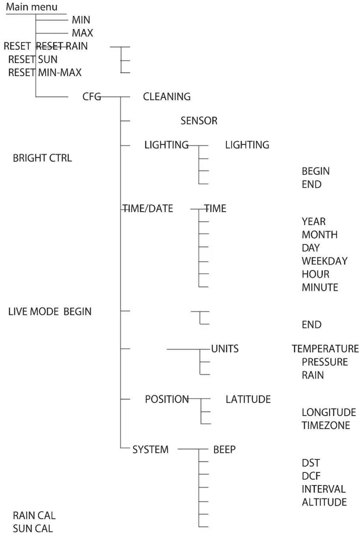
flowchart
graph TD
    A["Main menu"] --> B["MIN"]
    A --> C["MAX"]
    B --> D["RESET"]
    B --> E["RESET RAIN"]
    B --> F["SUN"]
    B --> G["RESET MIN-MAX"]
    C --> H["CFG"]
    H --> I["CLEANING"]
    I --> J["SENSOR"]
    I --> K["LIGHTING"]
    I --> L["LIGHTING"]
    J --> M["TIME/DATE"]
    K --> N["TIME"]
    L --> O["TIME"]
    M --> P["UNITS"]
    N --> Q["POSITION"]
    N --> R["LATITUDE"]
    P --> S["SYSTEM"]
    R --> T["BEEP"]
    S --> U["DST"]
    S --> V["DCF"]
    S --> W["INTERVAL"]
    S --> X["ALTITUDE"]
    Y["BRIGHT CTRL"] --> Z["TIME/DATE"]
    Y --> AA["TIME"]
    AB["LIVE MODE BEGIN"] --> AC["UNITS"]
    AB --> AD["LATITUDE"]
    AB --> AE["SYSTEM"]
    AB --> AF["BEEP"]
Table of coordinates for selected locations in Germany
| Location | Latitude | Longitude | |
| Aachen 50.8° 6.1° | |||
| Augsburg | 48.4° | 10.9° | |
| Berlin | 52.5° | 13.4° | |
| Bonn 50.7° 7.1° | |||
| Bremen 53.1° 8.8° | |||
| Chemnitz | 50.8° | 12.9° | |
| Dortmund 51.5° 7.5° | |||
| Dresden | 51.1° | 13.8° | |
| Duisburg 51.4° 6.8° | |||
| Düsseldorf 51.2° 6.8° | |||
| Erfurt | 51.0° | 11.0° | |
| Flensburg | 54.8° | 9.4° | |
| Frankfurt am Main | 50.1° | 8.7° | |
| Freiburg im Breisgau | 48.0° | 7.9° | |
| Hamburg | 53.6° | 10.0° | |
| Hannover | 52.2° | 9.7° | |
| Jena | 50.9° | 11.6° | |
| Karlsruhe | 49.0° | 8.4° | |
| Kassel | 51.3° | 9.5° | |
| Kiel | 54.3° | 10.1° | |
| Cologne | 50.9° | 7.0° | |
| Leer/ Ostfriesland | 53.2° | 7.4° | |
| Leipzig | 51.3° | 12.4° | |
| Magdeburg | 52.1° | 11.6° | |
| Mainz | 50.0° | 8.3° | |
| Munich | 48.1° | 11.6° | |
| Nuremberg | 49.5° | 11.1° | |
| Oberhausen | 51.5° | 6.8° | |
| Oldenburg (Oldb.) | 53.1° | 8.2° | |
| Saarbrücken | 49.3° | 7.0° | |
| Schwerin | 53.6° | 11.4° | |
| Stuttgart | 48.8° | 9.2° | |
| Wiesbaden | 50.1° | 8.3° | |

eQ-3 AG
Maiburger Straße 29
D-26789 Leer
www.eQ-3.com