PowerWalker VI 1500RT LCD - Inverter BlueWalker - Free user manual and instructions
Find the device manual for free PowerWalker VI 1500RT LCD BlueWalker in PDF.

User questions about PowerWalker VI 1500RT LCD BlueWalker
0 question about this device. Answer the ones you know or ask your own.
Ask a new question about this device
Download the instructions for your Inverter in PDF format for free! Find your manual PowerWalker VI 1500RT LCD - BlueWalker and take your electronic device back in hand. On this page are published all the documents necessary for the use of your device. PowerWalker VI 1500RT LCD by BlueWalker.
USER MANUAL PowerWalker VI 1500RT LCD BlueWalker
Line Interactive UPS
PowerWalker VI 1000RT LCD
PowerWalker VI 1500RT LCD
PowerWalker VI 2000RT LCD
PowerWalker VI 3000RT LCD
EN
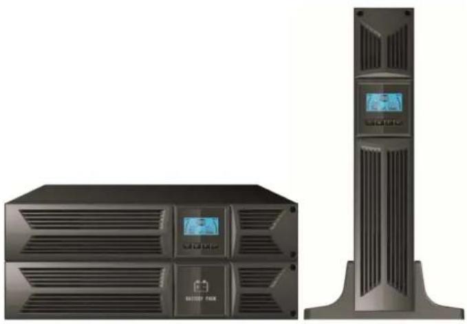
natural_image
Exterior view of a server rack and tower unit (no visible text or symbols)Manual
EN, DE
IMPORTANThSAFETYhINSTRUCTIONS
SAVE THESE INSTRUCTIONS – This manual contains important instructions for models PowerWalker VI 1000/1500/2000/3000 RT LCD that should be followed during installation and maintenance of the UPS and batteries.
EN
- This product is specially designed for PCs and it is not recommended for use in any life-supporting system and other specific important equipment.
- This equipment can be operated by any individual with no previous training.
- Do not plug household appliances such as hair dryers to UPS receptacles.
- This unit intended for installation in a controlled environment (temperature controlled, indoor area free of conductive contaminants). Avoid installing the UPS in locations where there is standing or running water, or excessive humidity.
- Risk of electric shock, do not remove cover. No user serviceable parts inside. Refer servicing to qualified service personnel.
- The utility power outlet shall be near the equipment and easily accessible. To isolate UPS from AC input, remove the plug from the utility power outlet.
- If UPS is to be stored for a long time, it is recommended to recharge the batteries (by connecting the utility power to UPS, switch "ON"), once a month for 24 hours to avoid a full battery discharge.
- Please do not use the UPS in excess of the rated load capacity.
- The UPS contains one or more large-capacity batteries. So the shell shall not be opened, otherwise such dangers as electric shock will be caused. If any internal overhaul or replacement of the battery is required, please contact the distributor.
- The internal short circuiting of the UPS will lead to dangers such as electric shock or fire, therefore, no water containers (such as a water glass) shall be placed on the top of the UPS so as to avoid such dangers as electric shock.
- Do not dispose of battery or batteries in a fire. The battery may explode.
- Do not open or mutilate the battery or batteries. Released electrolyte is harmful to the skin and eyes. It may be toxic.
- Icon on the rating label stands for phase symbol.
- A battery can present a risk of electrical shock and high short circuit current. The following precautions should be observed when working on batteries
- Remove watches, rings, or other metal objects from the hand.
- Use tools with insulated handles.
- Servicing of batteries should be performed or supervised by personnel knowledgeable of batteries and the required precautions. Keep unauthorized personnel away from batteries.
EN
- When replacing batteries, replace with the same type and number of the sealed lead-acid batteries.
• The maximum ambient temperature rating is 40^ C.
- This pluggable type A equipment with battery already installed by the supplier is operator installable and may be operated by laymen.
- During the installation of this equipment it should be assured that the sum of the leakage currents of the UPS and the connected loads does not exceed 3.5mA.
- Attention, hazardous through electric shock. Also with disconnection of this unit from the mains, hazardous voltage still may be accessible through supply from battery. The battery supply should be therefore disconnected in the plus and minus pole of the battery when maintenance or service work inside the UPS is necessary.
- The mains socket outlet that supplies the UPS shall be installed near the UPS and shall be easily accessible.
- In case smoke is found coming out from the device, please cut off the power supply quickly and contact the distributor.
- Do not keep or use this product in any of the following environments:
- Any area with combustible gas, corrosive substance or heavy dust.
- Any area with extraordinarily high or low temperature (above 40°C or below 0°C) and humidity of more than 90%.
- Any area exposed to direct sunshine or near any heating apparatus.
- Any area with serious vibrations.
o Outdoor.
- In the event that there is fire occurring in the vicinity, please use dry-power extinguishers. The use of liquid extinguishers may give rise to the danger of electric shock.
CONTENTS
- Introduction ...... 5
- Safety Warning 2
2.1 Description of Commonly Used Symbols 2
EN
- Installation....3
3.1 Inspection of Unit 3
3.2 Unpacking the Cabinet 3
3.3 UPS Setup 3
3.4 EBM Installation (Optional) 8
3.5 UPS Initial Startup 14
- Operation.... 15
4.1 Display Panel 15
4.2 Operating Mode 19
4.3 Configuring Load Segment 19
4.4 Configuring UPS for EBM Numbers 20
4.5 Configuring Green Function 20
- Communication Port 21
5.1 RS-232 and USB Communication Ports 21
5.2 Emergency Power Off (EPO) 21
5.3 Network Management Card (Optional) 22
- UPS Maintenance....23
6.1 UPS and Battery Care 23
6.2 Storing the UPS and Batteries 23
6.3 Time to Replace Batteries 23
6.4 Replacing UPS Internal Batteries 24
6.5 Testing New Batteries 26
6.6 Recycling the Used Battery: 26
- Specification 27
7.1 Specification 27
7.2 Rear Panels 29
- Trouble Shooting 32
8.1 Audible Alarm Trouble Shooting 32
8.2 General Trouble Shooting 32
- Software Installation....33
1. Introduction
This line-interactive series is compact and pure sine wave UPS and it is designed for essential applications and environment, such as desktops, servers, workstations, and other networking equipments. These models are available in the output ratings of 1000VA, 1500VA, 2000VA and 3000VA. The series protects your sensitive electronic equipments against power problems including power sags, spike, brownouts, line noise, undervoltage, overvoltage and blackouts.
EN
The series is convertible to rack and tower forms. It can be placed either in Rack 2U or Tower form. The front panel of the UPS includes LCD display and four control buttons that allow users to monitor, configure and control the units. On LCD, it also includes a LCD graphical bar, two status indications and four alarm indications. A control button from the front panel allows users to silence off the AC fail alarm and initiate the UPS self test sequence as well. The UPS case for 1000VA \~ 3000VA is made of metal. This series is powered from the AC mains and supply AC outputs via receptacles on the rear panel. Communication and control of UPS is available through serial or USB ports located on the rear panel. The serial port will support communications directly with a server and offer dry-contacts.
Features:
■ Microprocessor control guarantees high reliability
■ High frequency design
■ Built-in boost and buck AVR
■ Easy battery replacement design
■ Selectable input and output range
■ Cold start capability
■ Built-in Dry contact/RS-232/USB communication port
■ Optional SNMP module allows web-based remote or monitoring management
■ Enable to extend runtime with scalable external battery module(EBM)
■ Overload, short-circuit, and overheat protection
■ Rack/Tower 2-in-1 Design
■ 19 inches rack mount available for all models
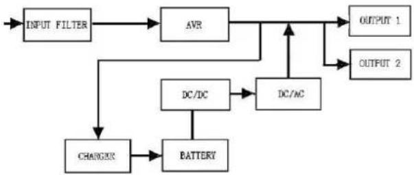
2. Circuit Configuration and Commonly used Symbols
EN
Following figure shows the basic internal circuit configuration of the UPS
flowchart
graph TD
    A["INPUT FILTER"] --> B["AVR"]
    B --> C["OUTPUT 1"]
    B --> D["OUTPUT 2"]
    B --> E["DC/DC"]
    E --> F["DC/AC"]
    F --> C
    E --> G["BATTERY"]
    G --> H["CHARGUS"]
    H --> A
2.1 Description of Commonly Used Symbols
Some or all of the following Notations may be used in this manual and may appear in your application process. Therefore, all users should be familiar with them and understand their explanations.
Table1. Description of Commonly Used Symbols
| Symbol | Description |
 | Alert you to pay special attention |
 | Caution of high voltage |
 | Alternating current source (AC) |
| [60TH] | Direct current source(DG) |
 | Protective ground |
 | Recycle |
 | Keep UPS in a clear area |
3. Installation
3.1 Inspection of Unit
Inspect the UPS upon receiving. If the UPS is apparently damaged during the shipment, please keep the box and packing material in original form for the carrier and notify the carrier and dealer immediately.
EN
3.2 Unpacking the Cabinet
To unpack the system:
- Open the outer carton and remove the accessories packaged with the cabinet.
- Carefully lift the cabinet out of the outer carton and set it on a flat, stable surface.
- Discard or recycle the packaging in a responsible manner, or store it for future use.
Package content: UPS, Input Power Cord, 2x IEC cable, Tower Holder, Rack Ears, EPO Plug, USB cable, Software CD, manual
3.3 UPS Setup
All model series are designed for tower and rack purpose. They can be installed into a 19 inches equipment rack. Please follow the instruction for Tower Setup and Rack-Mount Setup.
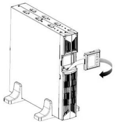
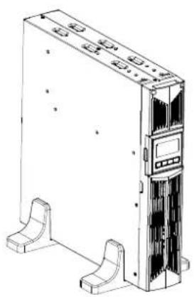
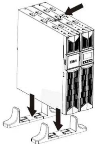
- Tower setup
This series of UPS can be placed horizontally and vertically. As a tower configuration, it is provided with the optional UPS stands to stabilize the UPS when the UPS is positioned in vertical. The UPS stand must be attached to the bottom of the tower.
Use the following procedure to install UPS in UPS stands.
-
Slide down the UPS vertically and put two UPS stands at the end of the tower.
-
Place down the UPS into two stands carefully.
-
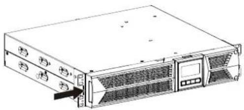
Pull out the LCD box and rotate it in a clockwise direction to 90 degree and then push it back in the front panel.
natural_image
Technical line drawing of a server rack with a door and switch, showing internal components and mounting base (no text or symbols)EN
natural_image
Line drawing of a server rack unit with front panel and side connectors (no text or symbols)- Rack-mount setup
The series can be installed in 19 inches racks. Both the UPS and external battery enclosure need 2U of valuable rack space.
Use the following procedure to install UPS in a rack.
EN
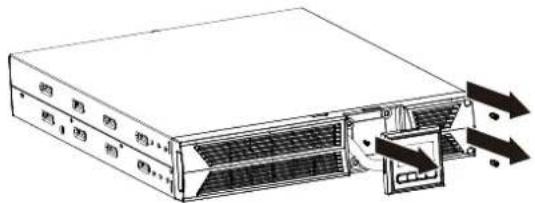
- Align the mounting ears with screw holes on the side of the UPS, and tighten the screw.
natural_image
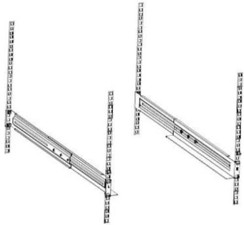
Line drawing of a server rack unit with ventilation grilles and drive bays (no text or symbols)- Assemble the rack rails with the rack-mounting.
natural_image
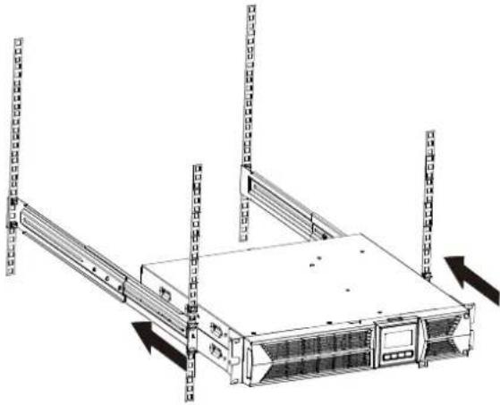
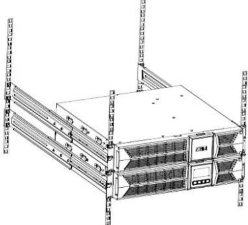
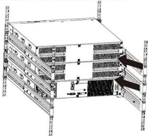
Technical line drawing of two structural panel designs with vertical supports and horizontal beams (no text or symbols)- Slide in the UPS into the rack rail and lock it in the rack enclosure.
natural_image
Diagram of a server rack with multiple vertical racks and directional arrows indicating movement (no text or symbols present)EN
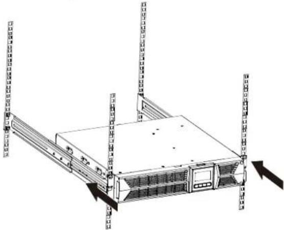
- Tighten the screw, and the load can then be connected.
natural_image
Line drawing of a server rack unit with multiple vertical racks and directional arrows indicating movement (no text or symbols)3.4 EBM Installation (Optional)
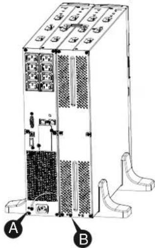
- Connecting the EBM in Tower form:
- Slide down the UPS and EBM vertically and place two UPS stands with the extend part at the end of the tower.
- Tighten the screw on the metal sheet for stabilization
natural_image
Diagram of a server rack unit with mounting base and internal components, showing no text or symbols- Connect the Earth line from UPS (port A) to EBM (port B)
text_image
Technical diagram of an industrial server rack with labeled components A and BEN
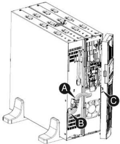
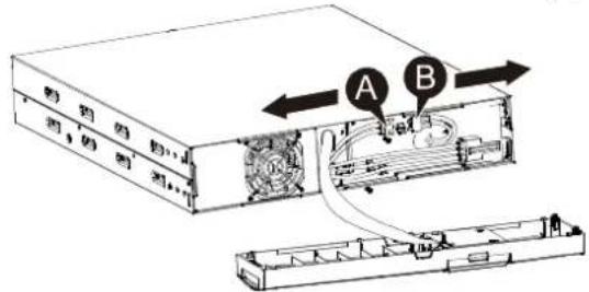
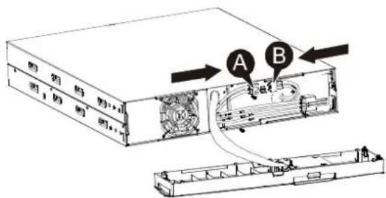
- Take off the front panel, and connect the battery terminal (A) from UPS to EBM terminal (B) shown as below. Users need to remove the small gate(C) on side of the front panel to allow the outlet wire of the EBM to pass through the gate and then reassemble front panel.
EN
text_image
Technical diagram of a server rack with labeled components A, B, and C showing internal wiring and ventilation system- Connecting the EBM in a rack form
- Using the same method as assembling UPS in a rack form, assemble EBM into the rack-mounting on the top or bottom of the UPS.
natural_image
Line drawing of a server rack unit with multiple racks and ventilation units (no text or symbols)- Connect the earth line from UPS (port A) to EBM (port B)
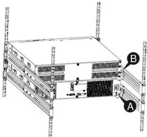
text_image
Technical diagram of a server rack with labeled components A and B, showing internal structure and mounting points.EN
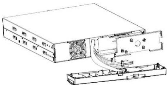
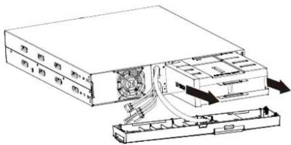
- Take off the LCD box, and unscrew the internal screws.
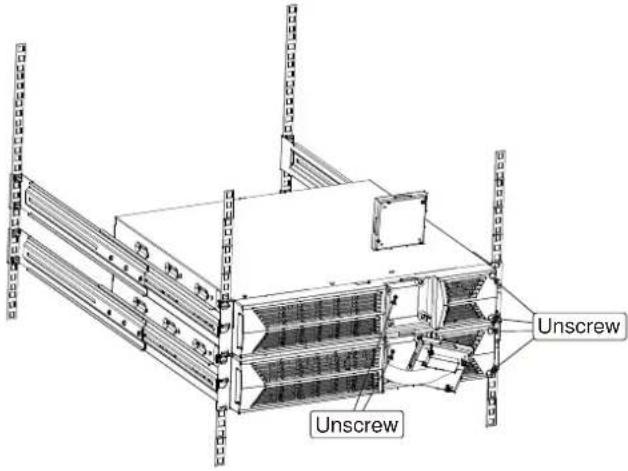
text_image
Unscrew Unscrew- Take off the front panel, and connect the battery terminal (A) from UPS to EBM terminal (B) shown as below. Users need to remove the small gate(C) on side of the front panel to allow the outlet wire of the EBM to pass through the gate and then reassemble front panel.
EN
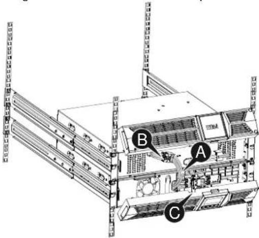
text_image
Technical diagram of a server rack with labeled components A, B, and C- After installing the UPS into rack, the load can then be connected to UPS. Please make sure the load equipment is turned off before plugging all loads into the output receptacle.
- Connecting the Multiple EBMs
1000VA/1500VA/2000VA and 3000VA UPS include external battery port that allows users to connect multiple EBM in order to provide additional backup time. Follow the procedure to install multiple EBM as below.
Connecting multiple EBMs in Tower form
- Connect Earth line between UPS and the first EBM, and then connect Earth Line between the first EBM and the second EBM.
natural_image
Technical line drawing of a server rack unit with multiple drive bays and ventilation grilles (no text or labels)EN
- Take off the front panel, and connect the battery terminal (A) from UPS to EBM terminal (B) shown as below. And then connect the battery terminal (D) from the first EBM to the battery terminal (E) from the second EBM. Users need to remove the small gate(C) on side of the front panel to allow the outlet wire of the EBM to pass through the gate and then reassemble front panel.
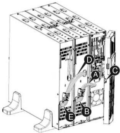
text_image
Technical diagram of an industrial server unit with labeled components A, B, C, D, E and internal wiring connectionsConnecting the Multiple EBMs in rack form
- Connect Earth line between UPS and the first EBM, and then connect Earth Line between the first EBM and the second EBM.
natural_image
Technical diagram of a server rack with multiple drive bays and mounting brackets (no text or labels)EN
- Take off the front panel, and connect the battery terminal (A) from UPS to EBM terminal (B) shown as below. And then connect the battery terminal (D) from the first EBM to the battery terminal (E) from the second EBM. Users need to remove the small gate(C) on side of the front panel to allow the outlet wire of the EBM to pass through the gate and then reassemble front panel.
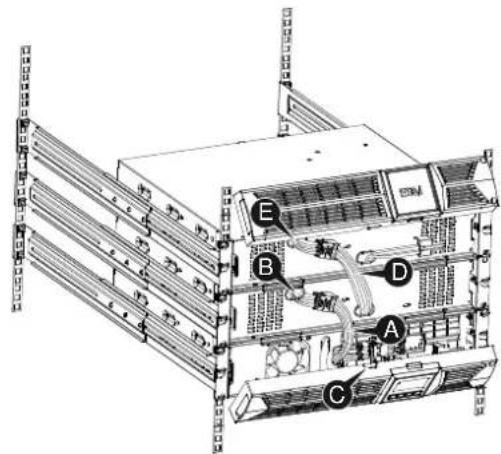
text_image
Technical diagram of a server rack with labeled components A, B, C, D, and ENote: Three or more EBMs can be connected to the UPS in the same way as shown above.
3.5 UPS Initial Startup
To start up the UPS:
- Verify that the internal batteries are connected. If optional EBMs are installed, verify that the EBMs are connected to the UPS.
- Plug the equipment to be protected onto the UPS, but do not turn on the protected equipment.
- Plug in the UPS input power cord. The UPS front panel display illuminates and UPS status display shows "STbY"
- Press and hold the button more than 3 seconds. The UPS status display changes to "NORM"
- Check the UPS display for active alarms or notices. Resolve any active alarms before continuing. See "Troubleshooting"
- If optional EBMs are installed, see "Configuring UPS for EBM numbers" on page 21 to set the number of installed EBMs.
- To change any other factory-set defaults, see "Operation"
Note: At initial startup, the UPS sets system frequency according to input line frequency.
EN
4. Operation
4.1 Display Panel
EN
The UPS has a four-button graphical LCD with dual color backlight. Standard back-light is used to light up the display with black text and a blue background. When the UPS has a critical alarm, the backlight changes the background to red. See Figure below:
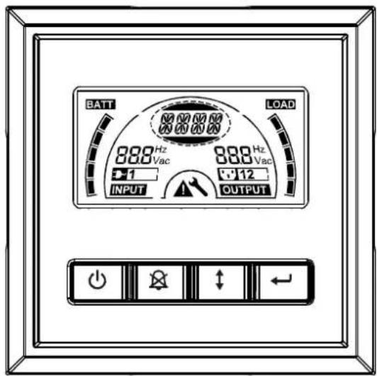
text_image
BATT 888 Hz Vac +1 INPUT LOAD 888 Hz Vac +12 OUTPUT● Control Buttons functions:
There are four buttons on the control panel.
ON/OFF
UPS Test /Alarm Silence
Select
Enter
The following table describes the functions of the LCD control buttons.
Table2. Description of control button
| Control Button | Switch Function |
| ON/OFF--To turn on/off the UPSPress and hold the buttonmore than 3 seconds.--To release the UPS from faulty modeCut off input power and then press and hold the buttonmore than 2 seconds to shut down the UPS. | |
| UPS Test Alarm Silence--To perform basic function testPress and hold the buttonfor 3 seconds.--To perform Battery life testPress and hold the buttonfor 10 seconds.--To disable alarm buzzerPress the buttonfor one second. | |
| SelectPress the Select buttonto select the settings value one by one | |
| Enter--Enter settings modePress and hold the buttonmore than 3 seconds.--Enter settings itemPress and hold the Enter buttonmore than one second, the UPS allows users to configure the settings, and the settings string will flash.--Confirm settingsPress and hold the Enter buttonfor one second.--Exit Settings modePress and hold the Enter buttonfor 3 seconds or buttonfor 0.5 second. |
EN
Note: Ensure the battery is fully charged during line mode when conducting functional tests.
Note: A list of events shown as below is not able to disable alarm buzzer: Low Battery, Fan Failed, Fan Fault Time Out, and Overheat.
Note: User can disable the alarm buzzer when it's sounding, but an alarm will still sound when a new alarm event is encountered.
- LCD display functions:
The following table describes the functions of the LCD display.
Table3. Description of LCD display function
EN
| No. | Description Function | |
 | Input frequency and voltage | Indicate the value of input frequency and voltage |
 | Input plug indicator | Light on when the input power is at no loss. |
 | Output frequency and voltage | Indicate the value of output frequency and voltage |
 | Output plug indicator | The UPS has two groups of outlets. The output plug indicator will light on if there is output power respectively. |
 | UPS status/user setting display String | Strings Indicate the UPS status( see Table 4)Strings Indicate user setting options( see Table 5) |
 | Warning indication | Light on when the UPS is failure or alarm. |
 | Settings | Light on when the UPS under settings mode. |
   | Battery volume level display | Indicate the amount of battery volume remaining. Each battery volume level bar indicates a 20% of total battery volume |
   | Load capacity level display | Indicate the percentage of UPS load capacity which is being used by the protected equipment. Each LCD level bar indicates a 20% of the total UPS output capacity. |
- UPS Status Display String Description:
The following table shows the description of the LCD display string:
Table4. UPS Status Display String
| LCD Display String | Description |
| STbY UPS work at Standby mode | |
| IPVL Input voltage is too low | |
| IPVH Input voltage is too high | |
| IPFL Input frequency is too low | |
| IPFH Input frequency is too high | |
| NORM UPS work at Line mode | |
| AVR UPS work at AVR mode | |
| bATT UPS work at Battery mode | |
| TEST UPS work at battery life/function test mode | |
| OPVH Battery mode, the output is too high | |
| OPVL Battery mode, the output is too low | |
| OPST Output short | |
| OVLD Overload | |
| bATH | Battery voltage is too high |
| bATL Battery voltage is too low | |
| OVTP Internal temperature is too high | |
| FNLK Fan is locked | |
| bTWK Batteries are weak | |
- User Setting String Description:
The following table shows the options that can be changed by user.
Table5. User Setting String
| OPV | Output voltage mode select | [220]= 220V[230]= 230V[240]= 240V | |
| AVR | Input type select | [000]= Normal range mode[001]= Wide range mode[002]= Generator mode | |
| EbM | External battery module (EBM) | 0~9 is the number of external battery module | |
| TEST | Auto self-test | [000]=Disable | [001]=Enable |
| AR | Automatic restart | [000]=Disable | [001]=Enable |
| GF | Green function | [000]=Disable | [001]=Enable |
| bZ | Buzzer control | [000]=Disable | [001]=Enable |
| LS1 | Load segment 1 | [000]=Turn off | [001]=Turn on |
| LS2 | Load segment 2 | [000]=Turn off | [001]=Turn on |
4.2 Operating Mode
- Normal range mode: Under Input mode the UPS accepts AC input voltage range for +/-20%.
- Generator mode: Under generator mode, the low frequency transfer point can go as low as 40Hz and as high as 70Hz before being transferred to battery mode.
- Wide range mode: Under Input settings mode, the UPS accepts AC input voltage range for -30% \~ +20%.
- Battery mode
When the UPS is operating during a power outage, the alarm beeps once every four seconds and the LCD display string shows "bATT" to indicate the UPS work at battery mode.
If battery volume becomes low while in Battery mode, the alarm beeps once every second and the LCD display string shows "bATL".
- Standby mode
When the UPS is turned off and remains plugged into a power outlet, the UPS is on Standby mode. The LCD display string shows "STbY" to indicate that power is not available to your equipment. The battery recharges when necessary.
4.3 Configuring Load Segment
Load segment are sets of receptacles that can be controlled through the display. Each UPS has two configurable load segments. See "Rear Panels" on page 30 for load segment for each UPS model.
Note: This configuring can be operated when UPS is power on.
To configure the load segment through the display:
- Enter settings mode: Press and hold the Enter button → more than 3 seconds. Then UPS will transfer to setting mode.
- Select settings items: Press the Select button ⏻ to select the setting items show as Table 5.
- Enter settings item: When the LCD display "LS1" or "LS2", press the enter button more than one second to enter the setting item and the settings string will flash.
- Select setting value: Press the Select button ⏻ to select the settings value. Select the value [001] or [000] to set the desired load segment ON or OFF.
- Confirm settings: Press and hold the Enter button ← for one second, ups will return to current setting item.
EN
- Exit Settings mode: Press and hold the Enter button ☐ for 3 seconds or button ⏻ for 0.5 second to exit setting mode.
4.4 Configuring UPS for EBM Numbers
EN
To ensure the LCD displays the correct battery volume, configure the UPS for the correct number of EBMs:
-
Enter settings mode: Press more than 3 seconds to enter setting mode.
-
Select settings items: Press to select setting items as "EbM".
-
Enter settings item: Press ← more than one second to enter the setting item.
-
Select setting value: Press the Select button ☐ to select the number of EBM according to your UPS configuration.
-
Confirm settings: Press and hold the Enter button ← one second, ups will return to current setting item.
-
Exit Settings mode: Press and hold the Enter button ← for 3 seconds or button ⏻ for 0.5 second to exit setting mode.
4.5 Configuring Green Function
Green Function is that when an insignificant amount of load is detected, the UPS will shut down output automatically on battery mode.
The green function is disabled on default mode and user can configure Green Function through the display:
-
Enter settings mode: Press more than 3 seconds to enter setting mode.
-
Select settings items: Press ☐ to select setting items as "GF".
-
Enter settings item: Press more than one second to enter the setting item.
-
Select setting value: Press the Select button ☐ to select "001".
-
Confirm settings: Press and hold the Enter button for one second, ups will return to current setting item.
-
Exit Settings mode: Press and hold the Enter button for 3 seconds or button for 0.5 second to exit setting mode.
5. Communication Port
5.1 RS-232 and USB Communication Ports
To establish communication between the UPS and a computer, connect your computer to one of the UPS communication ports using an appropriate communication cable.
EN
When the communication cable is installed, power management software can exchange data with the UPS. The software polls the UPS for detailed information on the status of the power environment. If a power emergency occurs, the software initiates the saving of all data and an orderly shutdown of the equipment.
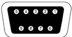
The cable pins for the RS-232 communication port are identified as below, and the pin functions are described in Table 6.
Table6. DB9 Female (RS232 +dry contact)
| PIN # | Description | I/O | Function Explanation |
| 1 | BATLOW Output Battery low | ||
| 2 | RXD input RXD | ||
| 3 | TXD Output TXD | ||
| 4 | DTR Input N/A | ||
| 5 | Common -- Common (tied to chassis) | ||
| 6 | DTR Input N/A | ||
| 7 | RING Output Ring | ||
| 8 | LNFAIL1 Output Line fail |
text_image
5 4 3 2 1 9 8 7 6RS232 Communication Port
5.2 Emergency Power Off (EPO)
EPO is used to shut down the load from a distance. This feature can be used for shutting down the load on Emergency.

Warning:
This circuit must be separated from hazardous voltage circuits by reinforced insulation.

Caution:
The EPO must not be connected to any utility connected circuits. Reinforced insulation to the utility is required. The EPO Switch must have a minimum rating of 24Vdc and 20mA and be a dedicated latching-type switch not tied into any other circuit. The EPO signal must remain active for at least 20ms for proper operation
EN
| EPO Connections | ||
| Wire Function | Terminal Wire Size Rating | Suggested Wire Size |
| EPO | 4-0.32m ^2 (12-22AWG) | 0.82mm ^2 (18AWG) |
Note: Leave the green EPO connector installed in the EPO port of the UPS even if the EPO function is not need. Remove the small cable from EPO connector.
EPO Connector
5.3 Network Management Card (Optional)
Network Management Card allows the UPS to communicate in a variety of networking environments and with different types of devices. The series UPS has one available communication slot for Webpower or other optional card to achieve remote management of the UPS through internet/ intranet. Please contact your local dealer for further information.
6. UPS Maintenance
6.1 UPS and Battery Care
EN
For the best preventive maintenance, keep the area around the UPS clean and dust-free. If the atmosphere is very dusty, clean the outside of the system with a vacuum cleaner. For long battery life, keep the UPS at an ambient temperature of 25^ C ( 77^ F)
6.2 Storing the UPS and Batteries
When the UPS is intended to store for a long period, recharge the battery every 6 months by connecting the UPS to utility power. The batteries charge to 90% capacity in approximately 4 hours. However, it is recommended that the batteries charge for 48 hours after long-term storage.
6.3 Time to Replace Batteries
When LCD backlight turns to red, the screen displays "bTWK" and there is a continuous sounding, the battery may need to be replaced. Please check the battery connection or contact your local dealer to order new battery.

WARNING:
- Turn off the UPS and disconnect the utility power cord from the wall outlet.
- Servicing should be performed by qualified service personnel knowledgeable of batteries and required precautions. Keep unauthorized personnel away from batteries
-
Batteries can present a risk of electrical shock or burn from high short circuit current. The following precautions should be observed:
-
Remove watches, rings, or other metal objects.
- Use tools with insulated handles.
- Do not lay tools or metal parts on top of batteries.
- Wear rubber gloves and boots.
- Disconnect the charging source prior to connecting or disconnecting battery terminal.
- When replacing batteries, replace with the same type and number of batteries or battery packs. Contact your service representative to order new batteries.
- Do not dispose of battery in a fire. Batteries may explode when exposed to flame.
- Proper disposal of batteries is required. Refer to your local codes for disposal requirements.
- Do not open or mutilate the battery. Released toxic electrolyte is harmful to skin and eyes.
EN
Note: If you are not qualified service personnel to replace the battery, do not attempt to open the battery cabin. Please call local dealer or distributor immediately.
6.4 Replacing UPS Internal Batteries
Follow the steps and Charts as below to replace batteries:
- Take off the LCD box, and remove the screws.
- Slide and Pull the front panel leftward and then take it off.
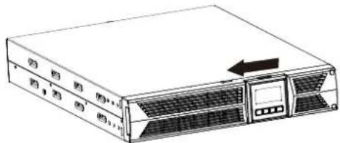
natural_image
Line drawing of a server rack unit with ventilation slots and an arrow indicating leftward motion (no text or symbols)- Disconnect the cable from the UPS and battery pack.
- Remove the right inner battery bracket.
- Pull the battery pack out onto flat area.
-
Install new battery pack into UPS.
-
Screw up the battery bracket and reconnect the battery cable A and B
text_image
A B- Re-install the front panel back to UPS.
6.5 Testing New Batteries
For a battery test, please check:
• The batteries must be fully charged.
- The UPS must be in Normal mode with no active alarms.
- Don't take on/off the load.
EN
To test batteries:
- Connect the UPS to utility power for at least 48 hours to charge the batteries.
- Press and hold the button 10 seconds to start the battery test. The status display string shows "TEST"
6.6 Recycling the Used Battery:

Warning:
- Never dispose the batteries in a fire. It may explode.
- Do not open or mutilate the batteries. Released electrolyte is harmful to the skins and eyes. It may be toxic. A battery can present a risk of electrical shock and high short circuit current.
To recycle properly the used battery, please do not discard the UPS, battery pack and batteries into the trash bin. Please follow your local laws and regulations; you may contact your local recycling waste management center for further information to dispose properly of the used UPS, battery pack, and batteries.
7. Specification
7.1 Specification
EN
Table7. Electrical Specification
| Model | 1000VA 1500VA 200VA 3000VA | ||||
| Capacity Watt | 900W 13 | 50W 1800W | 2700W | ||
| Input | Input voltage range | 161-276VAC | |||
| Frequency range | 50/60Hz ±5Hz for Normal Mode40-70Hz for Generator Mode | ||||
| Output | Voltage | 220/230/240VAC | |||
| Voltage Regulation(Batt. Mode) | ±5% | ||||
| Frequency | 50Hz or 60Hz | ||||
| Waveform | Pure sinewave | ||||
| Overload rating | Line Mode | 110%-0%, +8%: shutdown after 3 minutes.150%-0%, +10%: shutdown after about 200ms | |||
| Battery Mode | 110% ± 6%; shutdown after 30 seconds.120% ± 6%; Shutdown after about 100ms | ||||
| Internal battery | Battery Type | 3x 12V/7AH | 3x 12V/9AH | 6x 12V/7AH | 6x 12V/9AH |
| Backup Time(at full load) | 4'30" | 3' | 4'30" | 3' | |
| Recharge Time | 3 hours to90% afterdischarged | 4 hours to90% afterdischarged | 3 hours to90% afterdischarged | 4 hours to90% afterdischarged | |
| (EBM) Externalbattery module(optional) | Battery Type | 6x 12V/7AH | 6x 12V/7AH | 12x 12V/7AH | 12x 12V/7AH |
| Interface | RS-232 port | Yes | |||
| Dry-Contact-output | Yes | ||||
| AS/400 Card | Optional | ||||
| USB | Yes | ||||
| SNMP Card | Optional | ||||
| EPO port | Yes | ||||
Table8. Indicators and Audible alarm
| Indicator | AC Mode | NORM---normal mode |
| Backup Mode | Show “bATT” and sounding every 4 seconds | |
| Load/Battery Level | LCD showing | |
| UPS Fault | LCD show red screen and “ **** ” | |
| Overload | LCD show red screen and “ OVLD ” | |
| Low Battery | LCD show red screen and “ bTLW ” | |
| Audible alarm | Backup Mode | Sounding every 4seconds |
| Low Battery | Sounding every second | |
| UPS Fault | Continuously Sounding | |
| Overload | Sounding every second | |
| Battery Replacement | Sounding every second |
EN
Table9. Operating Environment
| Temperature | 0 to 40°C |
| Humidity | 20%-80% relative humidity (non-condensing) |
| Altitude | <1500m |
| Storage Temperature | -15° to 45°C |
Table10. Dimensions and weights
| Model 1000 1000S | 1500 | 1500S | 2000 | 2000S | 3000 | 3000S | |||
| UPS Case | Net weight (kg) | 17.8 | 10 17.8 | 0 27.8 | 16 27.8 | 16 | |||
| Dimension (mm)(W x H x D) | 438X86.5x436 | 438X86.5x608 | |||||||
| EBM Case | Dimension ( mm)(W x H x D) | 438X86.5x436 | 438X86.5x608 | ||||||
| Net weight (kg) | 20.5 33.3 | ||||||||
7.2 Rear Panels
The UPS rear panel description table and pictures are shown as below:
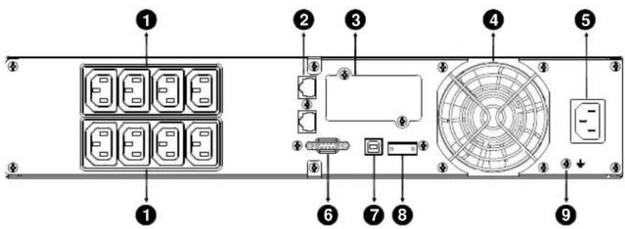
| No. | Function (1000VA &1500VA) |
| 1 AC Output | |
| 2 Modem/Network Surge Protection | |
| 3 | Intelligent Slot for SNMP or AS/400 card |
| 4 | AC Input |
| 5 | RS232 / Dry-Contact Communication Port |
| 6 | USB Port |
| 7 | EPO |
| 8 | Earth Line Port |
text_image
Diagram of a server rack with labeled components including ports, connectors, and an interface panel1000VA & 1500VA Standard & Super charger model rear panel
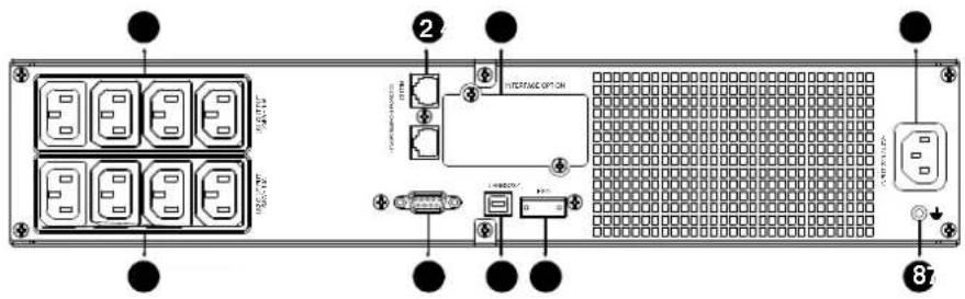
| No. | Function(2K/3KVA Standard & Supper charger model) |
| 1 | AC Output |
| 2 | Modem/Network Surge Protection |
| 3 | Intelligent Slot for SNMP or AS/400 card |
| 4 | Fan |
| 5 | AC Input |
| 6 | RS232 / Dry-Contact Communication Port |
| 7 | USB Port |
| 8 | EPO |
| 9 | Earth Line Port |
text_image
Diagram of a server rack with labeled components including drive, fan, and power connectionsEN
2000VA Standard model rear panel
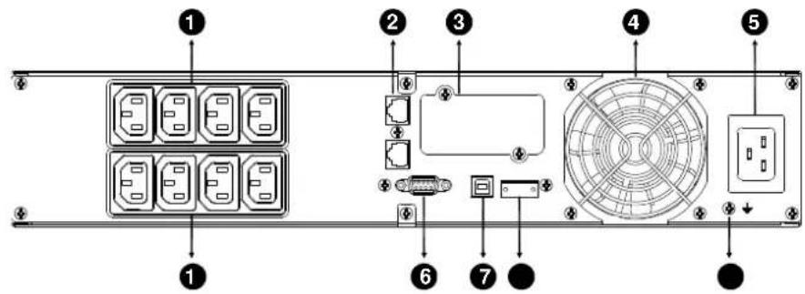
text_image
Diagram of a server rack with labeled components including drive, fan, and socket2000VA Super charger model rear panel
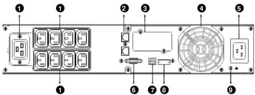
text_image
Diagram of a computer rack with labeled components including drive, fan, and socket ports3000VA Standard & Supper charger model rear panel
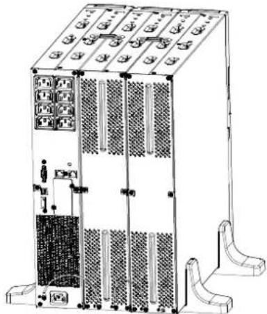
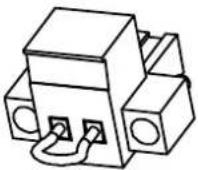
The EBM rear panel description table and picture are shown as below:
| No. | Function(36V &72V EBM) |
| 1 Earth Line Port | |
EN
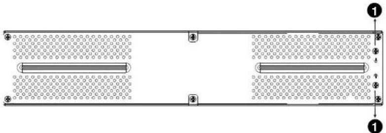
natural_image
Pure schematic diagram of a rectangular structure with two parallel plates and circular patterns, no text or symbols present.36V &72V EBM rear panel
8. Trouble Shooting
8.1 Audible Alarm Trouble Shooting
| Indication | Cause | Solution |
| Sounding every 4 seconds | The UPS is on battery mode | Check the input voltage |
| Sounding every Second and “bATL” on screen | The battery voltage is low | Save your work and turn off your equipment |
| Sounding every second and “OVLD” on screen | Output overload | Check load level indicator and remove some load |
| Continuously sounding and red display | The UPS fails Please contact your local dealer | |
EN
8.2 General Trouble Shooting
| Problem | Cause | Solution |
| The UPS can't be turned on when power switch is pressed | Internal fuse may be broken | Please contact your local dealer |
| UPS is on and no power to load | Output Jumpers is not connected correctly | Check output Jumpers |
| No power on output receptacle | Check if the LS1 and LS2 are set up from "001 to 000". | |
| Backup time is short | Battery is empty | Re-charge the battery at least 24 hours |
| Battery aging Replace Battery | ||
| Continuously sounding and display turn to red | The UPS fails Please contact your local dealer | |
| Buttons does not work | The setting mode is not a right path | please see right configuring method |
| Button is Broken Please contact your local dealer | ||
9. Software Installation
WinPower is UPS monitoring software, featuring user-friendly interface to monitor and control your UPS. This unique software provides complete power protection for computer system while power failure. With the software users can monitor any UPS status on the same LAN. Furthermore, a UPS can provide security protection for more than one computer on the same LAN at the same time, such as shutting down system in security, saving application data and shutting down the UPS when power fails.
EN
Software Installation on your PC:
Connected by USB to a PC or notebook, the Software enables communication between the UPS and the computer. The UPS software monitors the status of the UPS, shuts down the system before the UPS is exhausted and can remotely observe the UPS via the Network (enabling users to manage their system more effectively). Upon AC failure or UPS battery low, UPS takes all necessary actions without intervention from the system administrator. In addition to automatic file saving and system shut-down functions, it can also send warning messages via pager, e-mail etc.
- Use the bundled CD and follow the on-screen instructions to install the software WinPower.
• After the software is successfully installed, the communication with UPS has been established and an green icon will appear in the system tray.

9:16 AM
- Double-click the icon to use the monitor software (as above).
- You can schedule UPS shutdown/start-up and monitor UPS status through PC.
- Detail instructions please refer to the e-manual in the software.

Check http://www.powerwalker.com/winpower.html from time to time to get the latest version of monitoring software.
Line Interactive USV
PowerWalker VI 1000RT LCD
PowerWalker VI 1500RT LCD
PowerWalker VI 2000RT LCD
PowerWalker VI 3000RT LCD
DE

natural_image
Exterior view of a server rack and tower unit (no visible text or symbols)Bedienungsanleitung
EN, DE
2.1 Description of Commonly Used Symbols 7
DE
- INSTALLATION 8
3.1 ÜBERPRÜFUNG DES GERÄTS 8
3.2 AUSPACKEN DES SCHRANKS 8
3.3 USV-EINRICHTUNG 8
3.4 EBM-INSTALLATION (OPTIONAL) 13
3.5 ERSTMALIGE INBETRIEBNAHME DER USV 19
- BETRIEB 20
4.1 ANZEIGEFELD 20
4.2 BETRIEBSMODUS 24
4.3 KONFIGURIERENDES LASTSEGMENTS 24
4.4 KONFIGURIERENDER USV FÜR EBM-NUMMERN 25
4.5 KONFIGURIERENDER GREEN-FUNKTION 25
- KOMMUNIKATIONSANSCHLUSS 26
5.1 RS-232- UND USB-KOMMUNIKATIONSANSCHLÜSSE 26
5.2 NOTABSCHALTUNG (EMERGENCY POWER OFF, EPO) 27
5.3 NETWORK MANAGEMENT CARD (OPTIONAL) 27
- WARTUNG DER USV 28
6.1 PFLEGE VON USV UND BATTERIE 28
6.2 AUFBEWAHRUNG VON USV UNDBATTERIEN 28
6.3 ZEITPUNKT ZUM AUSTAUSCHEN DER BATTERIEN 28
6.4 AUSTAUSCHEN DER BATTERIEN IM INNEREN DER USV 29
6.5 TESTEN NEUER BATTERIEN 31
6.6 RECYCLING GEBRAUCHTER BATTERIEN: 31
- SPEZIFIKATION 32
7.1 SPEZIFIKATION 32
7.2 RÜCKSEITEN 34
natural_image
Technical line drawing of a server rack unit with two mounting brackets and directional arrows indicating assembly or movement (no text or symbols present)natural_image
Line drawing of a server rack unit with front panel and side legs (no text or symbols)natural_image
Technical line drawing of a server rack with a door and switch, showing internal components and a rotation arrow (no text or symbols)DE

natural_image
Line drawing of a server rack unit with front panel and side connectors (no text or symbols)- Rack-Montage
natural_image
Line drawing of a server rack unit with ventilation slots and drive bays (no text or symbols)natural_image
Technical line drawing of two structural frame components with vertical supports (no text or symbols)natural_image
Diagram of a server rack with multiple racks and a central unit, showing directional arrows indicating movement (no text or symbols present)natural_image
Diagram of a server rack with multiple vertical racks and a central control unit (no text or labels)3.4 EBM-Installation (Optional)
text_image
Diagram showing server rack with labeled components and directional arrows indicating movement or assemblynatural_image
Technical line drawing of a server rack unit with labeled components A and B (no text or symbols beyond labels)text_image
Technical diagram of a server rack with labeled components A, B, and Cnatural_image
Line drawing of a server rack unit with multiple racks and ventilation grilles (no text or symbols)text_image
Technical diagram of a server rack with labeled components A and B, showing internal structure and mounting points.text_image
Technical diagram of a server rack with labeled components A, B, and Cnatural_image
Technical line drawing of a multi-chamber industrial control unit with no visible text or symbolstext_image
Technical diagram of a server rack with labeled components A, B, C, D, E and ventilation ductstext_image
Technical diagram of a server rack with labeled components and directional arrows indicating movement or flow.DE
text_image
Technical diagram of a server rack with labeled components A, B, C, D, and Etext_image
BATT LOAD 888 Hz Vac 888 Hz Vac +1 -12 INPUT OUTPUT5.3 Network Management Card (Optional)
natural_image
Line drawing of a server rack unit with ventilation grilles and an arrow indicating leftward motion (no text or symbols)text_image
Diagram of a server rack with labeled components including ports, connectors, and a grid-patterned paneltext_image
Diagram of a server rack with labeled components including drive, fan, and socket portsDE