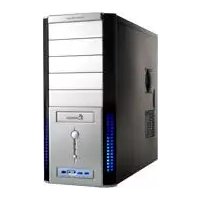
Centurion 534 +Plus - PC Case COOLER MASTER - Free user manual and instructions
Find the device manual for free Centurion 534 +Plus COOLER MASTER in PDF.


| Product Type | PC Case/Mid-Tower |
| Dimensions (W x H x D) | 201 x 430 x 480 mm |
| Weight | 8.0 kg (approx.) |
| Motherboard Support | ATX, Micro-ATX |
| Drive Bays - External 5.25" | 4 |
| Drive Bays - External 3.5" | 1 (converted from 5.25") |
| Drive Bays - Internal 3.5" | 6 |
| Expansion Slots | 7 |
| Included Fans | 1 x 120mm front, 1 x 120mm rear |
| Fan Options - Front | 2 x 120mm or 1 x 140mm |
| Fan Options - Rear | 1 x 120mm |
| Fan Options - Top | 1 x 120mm / 140mm (optional) |
| Power Supply Support | ATX PS/2 (not included) |
| Front Panel Ports | USB 2.0 x 2, Audio I/O |
| Construction Material | Steel, Plastic bezel |
| Side Panel | Windowed (acrylic) |
| Cooling System | Front mesh intake, tool-less drive rails |
| Dust Filters | Front bezel washable |
| Cleaning Instructions | Use a soft dry cloth; avoid liquids |
| Safety | Keep away from moisture; use original power supply |
| Spare Parts & Repairs | Contact Cooler Master support for replacement |
| General Information | Mid-tower with classic design, suitable for gaming/workstations |
Frequently Asked Questions - Centurion 534 +Plus COOLER MASTER
User questions about Centurion 534 +Plus COOLER MASTER
0 question about this device. Answer the ones you know or ask your own.
Ask a new question about this device
Download the instructions for your PC Case in PDF format for free! Find your manual Centurion 534 +Plus - COOLER MASTER and take your electronic device back in hand. On this page are published all the documents necessary for the use of your device. Centurion 534 +Plus by COOLER MASTER.
USER MANUAL Centurion 534 +Plus COOLER MASTER
Warranty Information
Cooler Master guarantees that this device is free of defect in material and workmanship, and provides a two-year limited hardware warranty for the device commencing from the date of purchase. Please keep your receipt for proof of purchase.
This product is designed for computer usage only. Using this device in any other capacity voids the warranty. If you are not familiar with computer hardware installation, please ask for professional assistance.
The warranty offered covers normal use. Defect or damage that result from improper operation, storage, misuse or abuse, accident or neglect, which are not the fault of Cooler Master, are exclude from warranty coverage.
Note: the warranty is voided by removal or alternation of product or parts identification labels.
Chapter 1: Product Overview
Specifications:
| Available Color Silver / Black | |
| Dimensions L480 x W202 x H435 mm | |
| Weight 9.7kg | |
| Material Aluminum & Mesh bezel, SECC chassis | |
| M/B Type ATX , m-ATX | |
| 5.25" Drive Bay 5 (Exposed) | |
| 3.5" Drive Bay 1 (Exposed); 4 (Hidden) | |
| Cooling System One 120x120x25mm rear fan(exhaust);One 120x120x25mm side fan (intake)One 120x120x25mm front fan (intake) (optional) | |
| I/O Panel USB2.0 x 2; MIC x 1; SPK x 1; IEEE1394 x 1 | |
| Power Supply | Standard ATX PS2, 380W. support LGA775 (optional) |
Diagram:

natural_image
Line drawing of a server rack cabinet with indicator lights and a control panel (no text or symbols)English
Parts list:
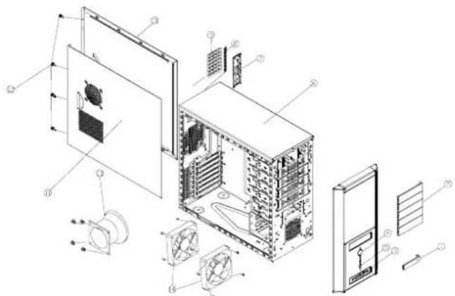
| Item | Part Name | Q'ty | Item Part | ||
| 1 | Small Shield | 1 | 8 | Latch | 1 |
| 2 | Big Shield | 5 | 9 | Interface card Shield | 7 |
| 3 | I/O Module | 1 | 10 | Right Side Casing | 1 |
| 4 | Power Key | 1 | 11 | Left Side Casing | 1 |
| 5 | Reset Key | 1 | 12 | Manual Screw | 4 |
| 6 | Casing | 1 | 13 | Air Scoop | 1 |
| 7 | IO panel | 1 | 14 | 120 Fan | 2 |
Fittings Pack
| Figure | Name | Q'ty | Used |
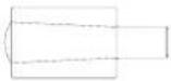 | 6.5mm Outer thick inner thin copper post | 2 | Used especially for positioning the mainboard. |
 | 6.5mm Outer thick inner thin copper post | 7 | Screw on the Mainboard tray |
 | 6.5mm Inner/outer thick copper post | 4 | For Xeon Only |
Screw Pack
| Figure | Name | Q'ty | Used |
 | M3*5 Screws | 19 | Screw on the Mainboard tray ,FDD |
 | 6*10 Screws | 4 | Installed on the mainboard to fix the CPU |
 | M3*7 Screws | 9 | Secures CD ROM |
Chapter 2: Installation
Removing side panels
- Loosen the screws manually; slide the side casing backward to remove it.
- To assemble it, please follow the above step reversely.

natural_image
Isometric line drawing of a computer tower internal structure showing exterior and internal components (no text or labels)Installing the Motherboard
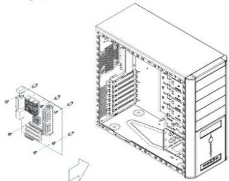
- Remove the side casing.
- Lie down the casing.
- Aiming at the holes on the PCB, and secure the alumnus post with screws.
- Align the holes of PCB and casing. Secure them by fastening screws on the PCB.
natural_image
Technical line drawing of a desktop computer tower showing internal components and exterior view (no text or labels)Install add-on card
- Press to loosen the latch on the inner casing.
- Insert the add-on card.

natural_image
Technical diagram showing layered electronic components and a circular inset view of a server unit (no text or symbols present)English
- Lock the latch back from the outside of the casing.

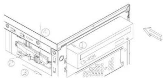
Installing Drives (CD-ROM, FDD and HDD)
Hands on where is indicated by an arrow and exert some force to remove the front panel.

natural_image
Technical line drawings of a desktop computer tower and its internal components, showing front, side, and top views (no text or labels)- Installing Hardware Device on 5.25"3.5" or "HDD" bracket-- Layer III, IV, or V.
- Insert the hardware device in place; align the screw holes of the device with those of the HDD rack.
- Push forward the plastic handling and tightening it.
- Push the lock and the installation is done.

Installing the power device
- Remove side casing.
- Place the power supply in the power supply bracket with the power cord side facing forwards.
- Secure the power supply device with screws.
- Assemble the side casing and the installation is done.

natural_image
Diagram showing a computer unit connected to an internal server rack, with no visible text or symbols.Replacing/Installing the Case Fan
Change the Front Fan (optional)
- Remove the side casing.
- Loosen the lower and side screws to remove the HDD bracket.
- Loosen the fan screws from the front casing, and then remove the fan.
- Install the new fan and secure it with screws. Continue to put it back on the HDD rack and secure it with screws.
Change the Rear Fan
- Loosen the fan screws from the rear casing and remove the fan.
- Install the new fan and secure it with screws.

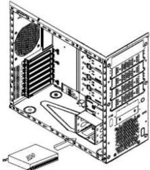
- Take out the HDD rail from the package. Install it on the HDD and have the screw holes aligned.
- Insert the assembled HDD into the hardware rack.
natural_image
Technical line drawing of a computer tower internal structure with CPU socket and drive unit (no text or labels)English
I/O Function Panel Installation Guide
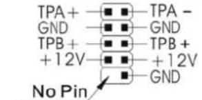
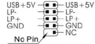
- Please refer to the illustration on the section of USB2.0, IEEE 1394, and Audio connector from the motherboard user manual. Please select the motherboard which used the same USB2.0, IEEE1394a, AC'97,HD Audio standard as below; otherwise, it will cause damages to device(s).
● The following illustration is a connection diagram for the front panel I/O cable. - NEVER connect an IEEE1394a cable to the USB2.0 connector. Doing so will damage the device.
- NEVER connect a USB2.0 cable to the IEEE1394a connector. Doing so will damage the device.
- On some motherboards, the connectors for IEEE1394a, USB2.0 and Audio are not the same as the drawing below. Please check with your motherboard manual before installing.
| Motherboard | Cable |
| Front panel IEEE 1394 connector | IEEE 1394 Connector |
 |  |
| Front panel USB connector | USB Connector |
 |  |
| AC'97 | AC'97 Connector |
 | |
| Azalia (Intel High Definition Audio) | HD Connector |
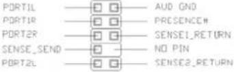 | 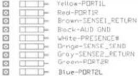 |

Contact us:
www.coolermaster.com
Email: info@coolermaster.com.tw
Headquarters, Taiwan
Tel: +886 2 32340050
Fax: +886 2 32340221


- Warranty Information
- Chapter 1: Product Overview
- English
- Parts list:
- Fittings Pack
- Screw Pack
- Chapter 2: Installation
- Removing side panels
- Installing the Motherboard
- Install add-on card
- Installing Drives (CD-ROM, FDD and HDD)
- Installing the power device
- Replacing/Installing the Case Fan
- Change the Front Fan (optional)
- Change the Rear Fan
- I/O Function Panel Installation Guide
- Contact us:
Brand : COOLER MASTER
Model : Centurion 534 +Plus
Category : PC Case