
LS-3100B - Home Theater ONKYO - Free user manual and instructions
Find the device manual for free LS-3100B ONKYO in PDF.

| Product Type | Home Theater Speaker System |
| Brand | Onkyo |
| Model | LS-3100B |
| Color | Black |
| Number of Speakers | 5 speakers + 1 subwoofer (5.1 channel) |
| Total Power Output | 500 W RMS |
| Frequency Response | 20 Hz - 20 kHz |
| Impedance | 6 ohms (front, center, surround), 8 ohms (subwoofer) |
| Dimensions (Front Speaker) | 200 x 300 x 150 mm each |
| Dimensions (Center Speaker) | 300 x 100 x 120 mm |
| Dimensions (Surround Speaker) | 150 x 200 x 120 mm each |
| Dimensions (Subwoofer) | 250 x 400 x 350 mm |
| Weight (Front Speaker) | 2.5 kg each |
| Weight (Center Speaker) | 1.8 kg |
| Weight (Surround Speaker) | 1.2 kg each |
| Weight (Subwoofer) | 8 kg |
| Power Supply | AC 120 V / 60 Hz (USA), AC 220-240 V / 50-60 Hz (EU) |
| Power Consumption | 150 W (max) |
| Connectivity | Speaker wire terminals, RCA subwoofer input, optical input, coaxial input, HDMI ARC |
| Remote Control | Included |
| Wall Mountable | Yes (surround speakers) |
| Warranty | 2 years |
Frequently Asked Questions - LS-3100B ONKYO
User questions about LS-3100B ONKYO
0 question about this device. Answer the ones you know or ask your own.
Ask a new question about this device
Download the instructions for your Home Theater in PDF format for free! Find your manual LS-3100B - ONKYO and take your electronic device back in hand. On this page are published all the documents necessary for the use of your device. LS-3100B by ONKYO.
USER MANUAL LS-3100B ONKYO
Connections ......14
Operations......17
Useful Function......21
Appendix......22
Thank you for purchasing an Onkyo product. Please read this manual thoroughly before making connections and plugging in your new Onkyo product.
Following the instructions in this manual will enable you to obtain optimum performance and listening enjoyment from your new product.
Please retain this manual for future reference.
WARNING:
TO REDUCE THE RISK OF FIRE OR ELECTRIC SHOCK, DO NOT EXPOSE THIS APPARATUS TO RAIN OR MOISTURE.
CAUTION:
TO REDUCE THE RISK OF ELECTRIC SHOCK, DO NOT REMOVE COVER (OR BACK). NO USER-SERVICEABLE PARTS INSIDE. REFER SERVICING TO QUALIFIED SERVICE PERSONNEL.

WARNING
RISK OF ELECTRIC SHOCK DO NOT OPEN
AVIS
RISQUE DE CHOC ELECTRIQUE NE PAS OUVRIR


The lightning flash with arrowhead symbol, within an equilateral triangle, is intended to alert the user to the presence of uninsulated “dangerous voltage” within the product’s enclosure that may be of sufficient magnitude to constitute a risk of electric shock to persons.

The exclamation point within an equilateral triangle is intended to alert the user to the presence of important operating and maintenance (servicing) instructions in the literature accompanying the appliance.
Important Safety Instructions
- Read these instructions.
- Keep these instructions.
- Heed all warnings.
- Follow all instructions.
- Do not use this apparatus near water.
- Clean only with dry cloth.
- Do not block any ventilation openings. Install in accordance with the manufacturer's instructions.
- Do not install near any heat sources such as radiators, heat registers, stoves, or other apparatus (including amplifiers) that produce heat.
- Do not defeat the safety purpose of the polarized or grounding-type plug. A polarized plug has two blades with one wider than the other. A grounding type plug has two blades and a third grounding prong. The wide blade or the third prong are provided for your safety. If the provided plug does not fit into your outlet, consult an electrician for replacement of the obsolete outlet.
- Protect the power cord from being walked on or pinched particularly at plugs, convenience receptacles, and the point where they exit from the apparatus.
-
Only use attachments/accessories specified by the manufacturer.
-
Use only with the cart, stand, tripod, bracket, or table specified by the manufacturer, or sold with the apparatus. When a cart is used, use caution when moving the
PORTABLE CART WARNING

natural_image
Silhouette of a person pushing a large object inside a circular frame (no text or symbols)cart/apparatus combination to avoid injury from tip-over.
-
Unplug this apparatus during lightning storms or when unused for long periods of time.
-
Refer all servicing to qualified service personnel. Servicing is required when the apparatus has been damaged in any way, such as power-supply cord or plug is damaged, liquid has been spilled or objects have fallen into the apparatus, the apparatus has been exposed to rain or moisture, does not operate normally, or has been dropped.
-
Damage Requiring Service
Unplug the apparatus from the wall outlet and refer servicing to qualified service personnel under the following conditions:
A. When the power-supply cord or plug is damaged,
B. If liquid has been spilled, or objects have fallen into the apparatus,
C. If the apparatus has been exposed to rain or water,
D. If the apparatus does not operate normally by following the operating instructions. Adjust only those controls that are covered by the operating instructions as an improper adjustment of other controls may result in damage and will often require extensive work by a qualified technician to restore the apparatus to its normal operation,
E. If the apparatus has been dropped or damaged in any way, and
F. When the apparatus exhibits a distinct change in performance this indicates a need for service.
- Object and Liquid Entry
Never push objects of any kind into the apparatus through openings as they may touch dangerous voltage points or short-out parts that could result in a fire or electric shock.
The apparatus shall not be exposed to dripping or splashing and no objects filled with liquids, such as vases shall be placed on the apparatus. Don't put candles or other burning objects on top of this unit.
- Batteries
Always consider the environmental issues and follow local regulations when disposing of batteries.
- If you install the apparatus in a built-in
installation, such as a bookcase or rack, ensure that there is adequate ventilation.
Leave 20 cm (8") of free space at the top and sides and 10 cm (4") at the rear. The rear edge of the shelf or board above the apparatus shall be set 10 cm (4") away from the rear panel or wall, creating a flue-like gap for warm air to escape.
Precautions
-
Recording Copyright—Unless it's for personal use only, recording copyrighted material is illegal without the permission of the copyright holder.
-
AC Fuse—The AC fuse inside the unit is not user-serviceable. If you cannot turn on the unit, contact your Onkyo dealer.
-
Care—Occasionally you should dust the unit all over with a soft cloth. For stubborn stains, use a soft cloth dampened with a weak solution of mild detergent and water. Dry the unit immediately afterwards with a clean cloth. Don't use abrasive cloths, thinners, alcohol, or other chemical solvents, because they may damage the finish or remove the panel lettering.
-
Power
WARNING
BEFORE PLUGGING IN THE UNIT FOR THE FIRST TIME, READ THE FOLLOWING SECTION CAREFULLY.
AC outlet voltages vary from country to country. Make sure that the voltage in your area meets the voltage requirements printed on the unit's rear panel (e.g., AC 230 V, 50 Hz or AC 120 V, 60 Hz).
The power cord plug is used to disconnect this unit from the AC power source. Make sure that the plug is readily operable (easily accessible) at all times.
For models with [POWER] button, or with both [POWER] and [ON/STANDBY] buttons:
Pressing the [POWER] button to select OFF mode does not fully disconnect from the mains. If you do not intend to use the unit for an extended period, remove the power cord from the AC outlet.
For models with [ON/STANDBY] button only: Pressing the [ON/STANDBY] button to select Standby mode does not fully disconnect from the mains. If you do not intend to use the unit for an extended period, remove the power cord from the AC outlet.
- Preventing Hearing Loss
Caution
Excessive sound pressure from earphones and headphones can cause hearing loss.
- Batteries and Heat Exposure
Warning
Batteries (battery pack or batteries installed) shall not be exposed to excessive heat as sunshine, fire or the like.
7. Never Touch this Unit with Wet Hands—
Never handle this unit or its power cord while your hands are wet or damp. If water or any other liquid gets inside this unit, have it checked by your Onkyo dealer.
8. Handling Notes
- If you need to transport this unit, use the original packaging to pack it how it was when you originally bought it.
- Do not leave rubber or plastic items on this unit for a long time, because they may leave marks on the case.
- This unit's top and rear panels may get warm after prolonged use. This is normal.
- If you do not use this unit for a long time, it may not work properly the next time you turn it on, so be sure to use it occasionally.
For U.S. models
FCC/IC Information for User IMPORTANT NOTE:
This equipment complies with FCC/IC radiation exposure limits set forth for an uncontrolled environment and meets the FCC radio frequency (RF) Exposure Guidelines in Supplement C to OET65 and RSS-102 of the IC radio frequency (RF) Exposure rules.
This equipment has very low levels of RF energy that it deemed to comply without maximum permissive exposure evaluation (MPE). But it is desirable that it should be installed and operated keeping the radiator at least 20 cm or more away from person's body (excluding extremities: hands, wrists, feet and ankles).
REMARQUE IMPORTANTE :
Changes or modifications not expressly approved by the party responsible for compliance could void the user's authority to operate the equipment.
NOTE:
This equipment has been tested and found to comply with the limits for a Class B digital device, pursuant to Part 15 of the FCC Rules. These limits are designed to provide reasonable protection against harmful interference in a residential installation. This equipment generates, uses and can radiate radio frequency energy and, if not installed and used in accordance with the instructions, may cause harmful interference to radio communications. However, there is no guarantee that interference will not occur in a particular installation. If this equipment does cause harmful interference to radio or television reception, which can be determined by turning the equipment off and on, the user is encouraged to try to correct the interference by one or more of the following measures:
- Reorient or relocate the receiving antenna.
- Increase the separation between the equipment and receiver.
- Connect the equipment into an outlet on a circuit different from that to which the receiver is connected.
- Consult the dealer or an experienced radio/TV technician for help.
This transmitter must not be co-located or operated in conjunction with any other antenna or transmitter.
THIS CLASS B DIGITAL APPARATUS COMPLIES WITH CANADIAN ICES-003.
For models having a power cord with a polarized plug:
CAUTION:
TO PREVENT ELECTRIC SHOCK, MATCH WIDE BLADE OF PLUG TO WIDE SLOT, FULLY INSERT.
This device complies with Industry Canada licence-exempt RSS standard(s). Operation is subject to the following two conditions: (1) this device may not cause interference, and (2) this device must accept any interference, including interference that may cause undesired operation of the device.
Replacement and mounting of an AC plug on the power supply cord of this unit should be performed only by qualified service personnel.
IMPORTANT
The wires in the mains lead are coloured in accordance with the following code:
Blue: Neutral
Brown: Live
As the colours of the wires in the mains lead of this apparatus may not correspond with the coloured markings identifying the terminals in your plug, proceed as follows:
The wire which is coloured blue must be connected to the terminal which is marked with the letter N or coloured black.
The wire which is coloured brown must be connected to the terminal which is marked with the letter L or coloured red.
IMPORTANT
The plug is fitted with an appropriate fuse. If the fuse needs to be replaced, the replacement fuse must approved by ASTA or BSI to BS1362 and have the same ampere rating as that indicated on the plug. Check for the ASTA mark or the BSI mark on the body of the fuse.
If the power cord's plug is not suitable for your socket outlets, cut it off and fit a suitable plug. Fit a suitable fuse in the plug.
For European Models

Hereby, Onkyo Corporation, declares that this LAP-301 is in compliance with the essential requirements and other relevant provisions of Directive 1999/5/EC.
- The subwoofer cabinet is made out of wood and is therefore sensitive to extreme temperatures and humidity, do not put it in locations subject to direct sunlight or in humid places, such as near an air conditioner, humidifier, bathroom, or kitchen.
- Do not put water or other liquids close to the speakers. If liquid is spilled over the speakers, the drive units may be damaged.
- Speakers should only be placed on sturdy, flat surfaces that are free from vibration. Putting them on uneven or unstable surfaces, where they may fall and cause damage, will affect the sound quality.
- Subwoofer is designed to be used in the upright vertical position only. Do not use it in the horizontal or tilted position.
- If the unit is used near a turntable, CD player or DVD player, howling or slipping of sound may occur. To prevent this, move the unit away from the turntable, CD player or DVD player, otherwise lower the unit's output level.
Use with a TV set
In general, Braun tubes used for color television sets, etc. are extremely sensitive and can be affected even by the magnetism of the earth. If a speaker system is used near them, therefore, discoloring or distortion of pictures will occur.
These speakers are not provided with magnetic shielding. If discoloration or distortion occurs, move the speakers apart from the television set.
Input Signal Warning
The speakers can handle the specified input power when used for normal music reproduction. If any of the following signals are fed to them, even if the input power is within the specified rating, excessive current may flow in the speaker coils, causing burning or wire breakage:
- Interstation noise from an untuned FM radio.
- Sound from fast-forwarding a cassette tape.
- High-pitched sounds generated by an oscillator, electronic musical instrument, and so on.
- Amplifier oscillation.
- Special test tones from audio test CDs and so on.
- Thumps and clicks caused by connecting or disconnecting audio cables (Always turn off your amplifier before connecting or disconnecting cables).
- Microphone feedback.
Package Contents
Make sure you have the following items:
Sound system controller (LAP-301)
| Remote controller (RC-858S) |
| AC adapter and Power cord*1 (→page 16) |
| Stereo mini plug cable 5 ft. (1.5 m) |
| Optical digital audio cable 5 ft. (1.5 m) |
| Front speakers (SLM-301) |
| Speaker stand × 2 |
| Speaker cable 10 ft. (3.0 m) × 2 |
| 12 thin rubber stoppers (For Front speakers and Subwoofer) |
| 8 thick rubber stoppers |
| Wire cable with eye bolt × 2 |
| Wireless subwoofer (SLW-301) |
| Power cord*1 (→page 16) |
| Quick Guide |
*1 (Australian models) The plug type varies from country to country. From the two supplied power cords, choose the one whose plug matches the type of your AC wall outlet.
* In catalogs and on packaging, the letter at the end of the product name indicates the color. Specifications and operations are the same regardless of color.
Features
Sound System Controller
• Powerful Digital Amplifier
- 20 W / Ch (4 Ω, 1 kHz, 0.8%, 2 Channels Driven, FTC)
- 20 W / Ch (4 Ω, 1 kHz, 0.8%, 2 Channels Driven, IEC)
• 2 2 W / C h (4 Ω, 1 kHz, 0.8%, 2 Channels Driven, JEITA)
• 2 Digital Inputs (Optical/Coaxial)
• 1 Analog Input (Mini Jack)
• Normal Mode for Wide Spread Surround
• Vocal Mode for Clear Voice (for News Program)
- Bluetooth ver.2.1+EDR (Enhanced Data Rate)
• Auto Standby Function
• Auto Power On Function
- Preset Remote Control Codes for Most TV Brands and Programming Function
Subwoofer
- Wireless Design for Free Setting and Powerful Sound
- Powered Bass Reflex Design
- 6-1/2 inch (16 cm) Cone
Front Speakers
- Detachable Speaker Stands for Greater Mounting Flexibility
- 2-1/2 inch (6.5 cm) Full-range Cone × 2


Labs, Inc. WOW HD and TruVolume technologies are incorporated under license from SRS Labs, Inc.
DOLBY DIGITAL
Manufactured under license from Dolby Laboratories. Dolby and the double-D symbol are trademarks of Dolby Laboratories.
Onkyo does not guarantee Bluetooth compatibility between the LAP-301 system and all Bluetooth-enabled devices.
For compatibility between the LAP-301 system and another device with Bluetooth technology, consult the device's documentation and dealer. In some countries, there may be restrictions on using Bluetooth devices. Check with your local authorities.
The Bluetooth ^® word mark and logos are registered trademarks owned by Bluetooth SIG, Inc. and any use of such marks by Onkyo is under license. Other trademarks and trade names are those of their respective owners.
Please read rating label at the bottom or rear panel of system for other safety information.
Bluetooth
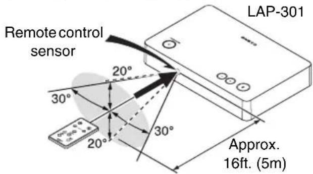
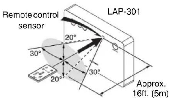
■Using the Remote Controller
Remove the plastic film before using the remote controller.
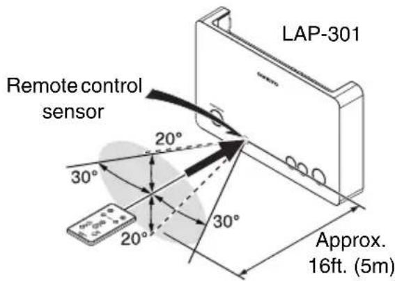
To use the remote controller, point it at the controller's remote control sensor, as shown below.
(Placing on the floor, etc.)
(Mounting to the wall)
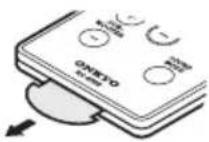
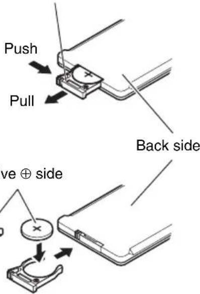
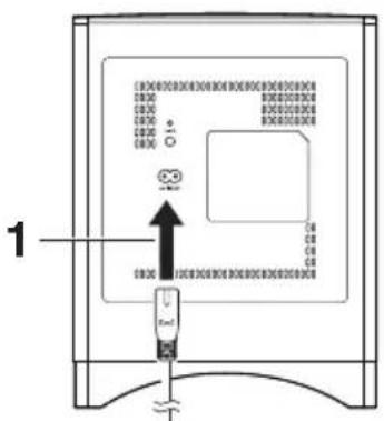
■Replacing the Battery
Use only a battery of the same type (CR2025).
Pull out firmly in the direction of the arrow pressing the tab in the direction of the arrow.
Note
- If the remote controller doesn't work reliably, try replacing the battery.
- If you intend not to use the remote controller for a long time, remove the battery to prevent damage from leakage or corrosion.
- Remove expired battery as soon as possible to prevent damage from leakage or corrosion.
Caution
- Replacing the battery incorrectly may cause an explosion. Use only a battery of the same type or an equivalent.
Getting to Know the LS3100
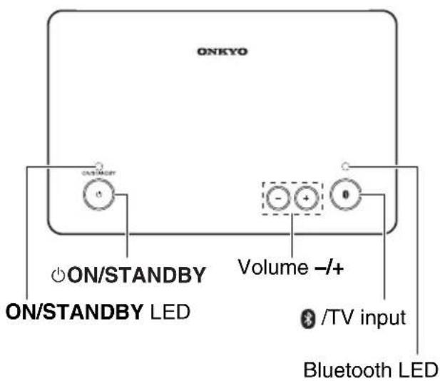
Top Panel (LAP-301)
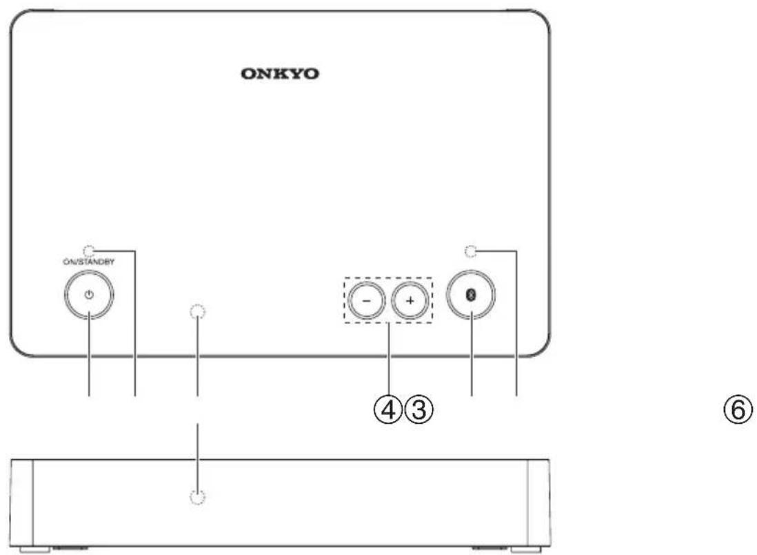
For detailed information, see the pages in parentheses.
① ON/STANDBY button (17)
② ON/STANDBY LED (17)
③ Remote control sensor (8)
④ Volume -/+ buttons (17)
⑤ TV input button (17)
⑥ Bluetooth LED (17)
Rear Panel (LAP-301)
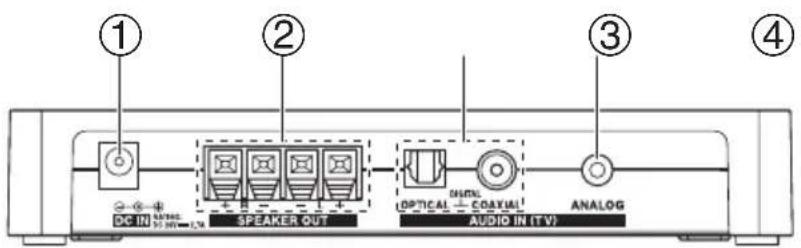
① DC IN jack
② SPEAKER OUT terminals
③ AUDIO IN (TV) DIGITAL OPTICAL and COAXIAL jacks
④ AUDIO IN (TV) ANALOG audio jack
See “Connections” for connection ( pages 14 to 16).
Front Speakers (SLM-301)
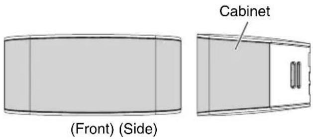
Caution
- The front grilles are not designed to be removed so do not attempt to remove them forcibly, as this will damage them.
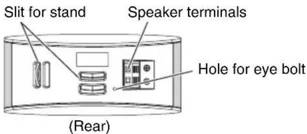
Subwoofer (SLW-301)
Note
- The shape of the AC INLET differs depending on the country.
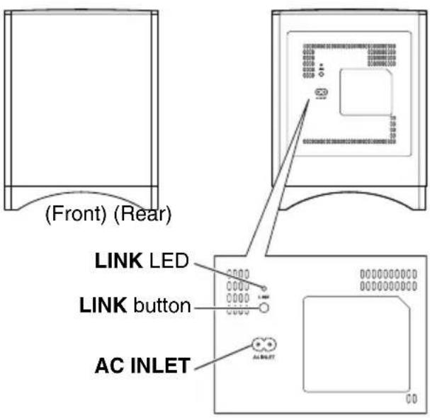
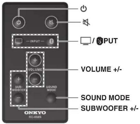
Remote Controller
For detailed information, see the pages in parentheses.
① ⏻ (On/Standby) button (17)
② ☐/✗ INPUT buttons (17)
③ VOLUME +/- buttons (17)
④ SUBWOOFER +/- buttons (18)
⑤ ⚙(Mute) button (18)
⑥ SOUND MODE button (19)
Using your TV remote controller
TV remote control commands of several TV brands are registered in the controller. These commands enable your TV remote controller to operate the Volume +/- and Mute function of the controller.
Tip
- Some types of TV remote controllers are not compatible with this function. In this case, use the supplied remote controller or perform the programming of the controller. See “Programming the controller for use of existing remote controller” for more details (→ page 21).
- If you operate the controller with your TV remote controller, set the Auto Power On function to on. The controller cannot be turned on by using Power On button on your TV remote controller.
Placement
This section explains how to mount/place the controller, the front speaker and the subwoofer.
In this instruction manual, Sound System Controller (LAP-301) is described as "controller".
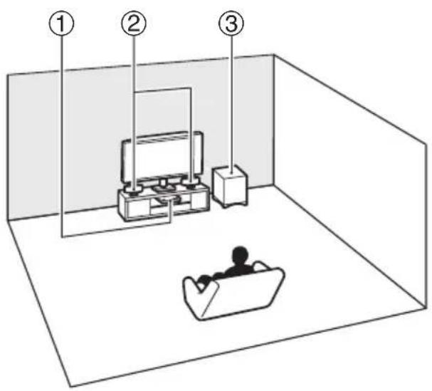
① Sound System Controller (LAP-301)
② Front speakers (SLM-301)
③ Subwoofer (SLW-301)
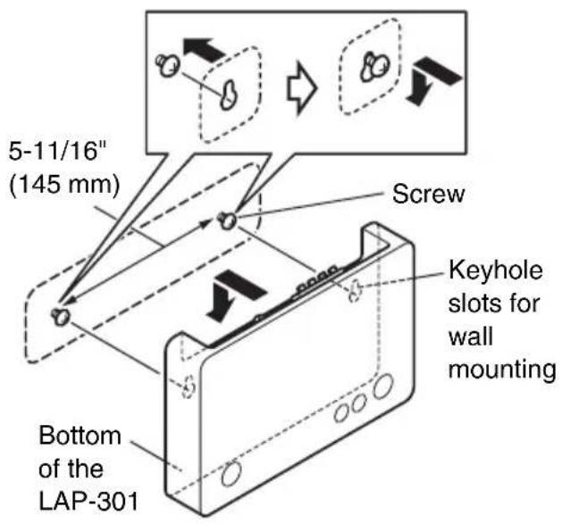
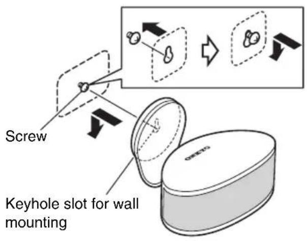
Mounting the Controller
The controller can be placed on the flat floor, and also mounted to the wall by using a commercially available wall-mounting screw.
■ Wall mounting
1 Mark the two points by using a pencil so that the controller can be mounted horizontally.
2 Insert a commercially available wall-mounting screw into the mark and screw it.
3 Insert the head of the screw into the keyhole slot on the bottom of the controller and fix it firmly.
Please confirm that the head of the screw is at the top of the hole.
Tip
- The controller can be mounted upside-down.
Caution
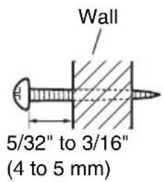
- For mounting the controller, use a screw with a head diameter of 1/4" (6 mm) or more and 2/32" (7 mm) or less, and a shank diameter of 1/8" (3 mm) or more and 5/32" (4 mm) or less. The screws as thick and long as possible are recommended.
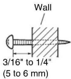
- Leave a gap of between 3/16" (5 mm) and 1/4" (6 mm) between the wall and the base of the screw head, as shown (We recommend that you consult a home installation professional).
- Mount the controller as close as possible to the TV set without hiding the remote control sensor for the TV remote controller.
- Mount the controller in a well-ventilated place.
Mounting/Placing the Front Speakers
Front speaker can be placed on the table top or mounted to the wall by using supplied stands.
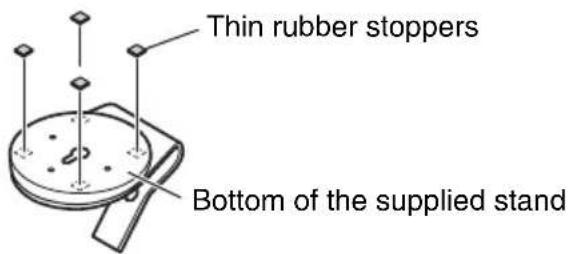
■ Using the rubber stoppers for a more stable platform
We recommend to use the supplied rubber stoppers to achieve the best possible sound. Attach the rubber stoppers to the four corners of the bottom. The rubber stopper also provides stability.
(Placing on the floor, etc.)
(Using the stand)
■Attaching the stand
Insert the stand into the stand slit on the rear of the front speaker.
(Table top)
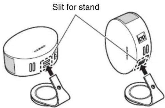
(Wall Mounting)
natural_image
Two technical line drawings of a device with labeled ports and connectors, no text or symbols present.Tip
- The front speaker can be mounted/placed both horizontally and vertically.
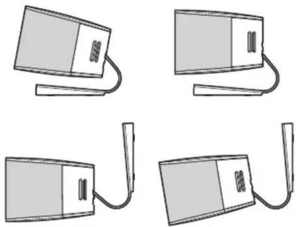
■Adjusting the angle
The angle of the speaker can be adjusted in two ways depending on which stand slit you use.
(Using the upper slit) (Using the lower slit)
natural_image
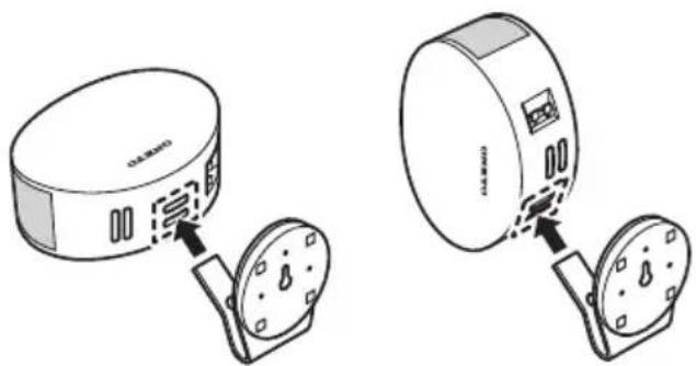
Four technical line drawings of a device with attached cables, shown in different angles (no text or symbols)■ Wall mounting
1 Attach the supplied stand referring to the illustration for wall mounting.
2 Screw a commercially available wall-mounting screw into the wall.
3 Insert the head of the screw into the keyhole slot on the bottom of the supplied stand and fix it firmly.
Please confirm that the head of the screw is at the top of the hole.
Note
- For mounting the front speaker, use a screw with a head diameter of 2/32" (7 mm) or more and 5/16" (9 mm) or less, and a shank diameter of 1/8" (3 mm) or more and 5/32" (4 mm) or less. The screws as thick and long as possible are recommended.
- Leave a gap of between 5/32" (4 mm) and 3/16" (5 mm) between the wall and the base of the screw head, as shown.
- Mount the front speaker to the vertical wall. Mounting to the inclined wall might cause a falling of the speaker by coming off the stand.
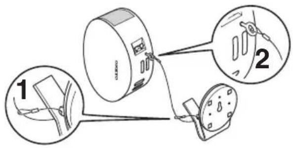
■Fixing the front speakers to prevent a falling accident
When you mount the speaker to the wall, make sure to set it firmly so that it cannot slip and fall. This is especially important if you have small children. Pass the end of the supplied wire through the hole of the stand and tie it. Screw the eye bolt into the eye bolt hole on the back of the cabinet.
Note
- A mounting screw's ability to support a speaker depends on the material and the position of studs of the wall (We recommend that you consult a home installation professional).
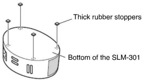
Placing the Subwoofer
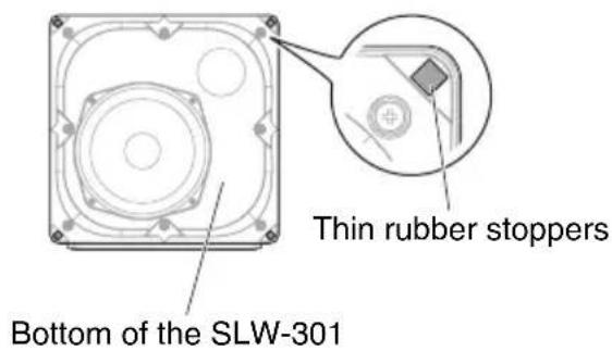
■Using the rubber stoppers for a more stable platform
We recommend to use the supplied rubber stoppers to achieve the best possible sound. Attach the rubber stoppers to the four corners of the bottom. The rubber stopper also provides stability.
Connections
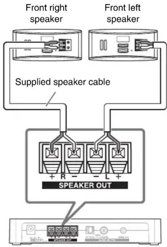
Connecting the Front Speakers
Connect the supplied front speaker. Connect positive (+) terminal of the front speaker to positive (+) terminal of the controller (LAP-301) and negative (-) terminal of the front speaker to negative (-) terminal of the controller.
flowchart
graph LR
    A["Device 1"] --> B["Device 2"]
    B --> C["Device 3"]
Tip
- The two speakers are identical, so it doesn't matter which one you use on the left or right.
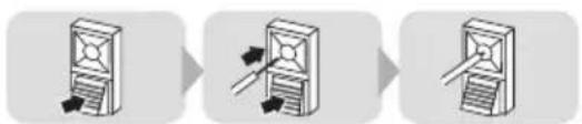
Speaker Connection Precautions
Read the following before connecting your speakers:
- You can connect speakers with an impedance of between 4 and 8 ohms.
- Disconnect the power cord from the wall outlet before making any connections.
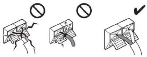
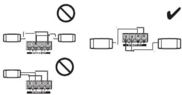
- Pay close attention to speaker wiring polarity. In other words, connect positive (+) terminals only to positive (+) terminals, and negative (-) terminals only to negative (-) terminals. If you get them the wrong way around, the sound will be out of phase and will sound unnatural.
- Be careful not to short the positive and negative wires. Doing so may damage the controller.
- Make sure the metal core of the wire does not have contact with the controller's rear panel. Doing so may damage the controller.
- Don't connect more than one cable to each speaker terminal. Doing so may damage the controller.
- Don't connect one speaker to several terminals.
flowchart
graph TD
    A["Switch"] --> B["No Symbol"]
    C["Switch"] --> D["No Symbol"]
    E["Switch"] --> F["No Symbol"]
    G["Switch"] --> H["No Symbol"]
    I["Switch"] --> J["No Symbol"]
    K["Switch"] --> L["No Symbol"]
    M["Switch"] --> N["No Symbol"]
    O["Switch"] --> P["No Symbol"]
    Q["Switch"] --> R["No Symbol"]
    S["Switch"] --> T["No Symbol"]
    U["Switch"] --> V["No Symbol"]
    W["Switch"] --> X["No Symbol"]
    Y["Switch"] --> Z["No Symbol"]
    AA["Switch"] --> AB["No Symbol"]
    AC["Switch"] --> AD["No Symbol"]
    AE["Switch"] --> AF["No Symbol"]
Using the Subwoofer
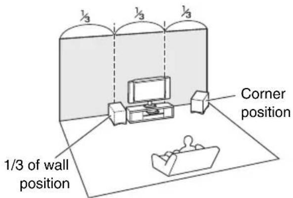
To find the best position for your subwoofer, while playing a movie or some music with good bass, experiment by placing your subwoofer at various positions within the room, and choose the one that provides the most satisfying results.
About TV Connections
- Before making any TV connections, read the manuals supplied with your TV.
- Don't connect the power cord until you've completed and double-checked the TV connection.
- Push plugs in all the way to make good connections (loose connections can cause noise or malfunctions).
• To prevent interference, keep audio cable away from power cords and speaker cables.
Cables and Jacks
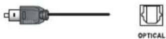
■Optical digital audio
Optical digital connection allows you to enjoy digital sound such as PCM or Dolby Digital. The audio quality is the same as coaxial.
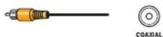
Coaxial digital audio
Coaxial digital connection allows you to enjoy digital sound such as PCM or Dolby Digital. The audio quality is the same as optical.
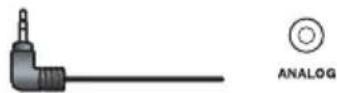
This cable carries analog audio.
Note
- The controller's optical digital jack has a shutter-type cover that open when an optical plug is inserted and close when it's removed. Push the plug in all the way.
Caution
• To prevent shutter damage, hold the optical plug straight when inserting and removing.
Connecting to the TV
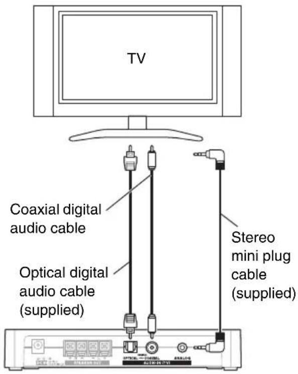
Connect the TV to either of the jacks of the controller.
Tip
- If the Dolby Digital signal is input, the ON/STANDBY LED flashes white and amber alternately three times.
Note
- Don't connect the different types of jacks together.
- When you find the both audio output from your TV and LS3100, turn the audio output from your TV speaker off by setting on the TV.
Connecting the Power cord
(LAP-301)
1 Connect the supplied AC adapter and the power cord.
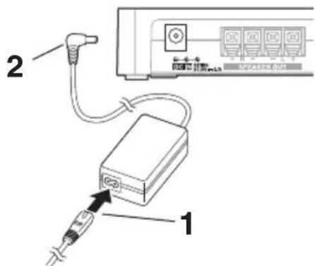
3 To AC wall outlet
2 Insert the plug of the AC adapter into DC IN.
3 Plug the AC adapter into an AC wall outlet.
(SLW-301)
1 Connect the supplied power cord for subwoofer to AC INLET.
2 To AC wall outlet
Note
• The shape of the AC INLET differs depending on the country.
2 Plug the power cord into an AC wall outlet.
Note
- Before connecting the power cord, connect all of your speakers and TV.
- Turning on the unit may cause a momentary power surge that might interfere with other electrical equipment on the same circuit. If this is a problem, plug the unit into a different branch circuit.
- Do not use the power cord other than the one supplied with the unit. The supplied power cord is designed exclusively for use with the unit and should not be used with any other equipment.
- Never disconnect the power cord from the unit while the other end is still plugged into a wall outlet. Doing so may cause an electric shock. Always disconnect the power cord from the wall outlet first, and then the unit.
Operations
Turning On the controller
1 Press ⏻ON/STANDBY on the top panel. or
Press ⏻ on the remote controller.
The controller comes on, and the ON/STANDBY LED lights white.
Press ⏻ON/STANDBY or ⏻ again to set the controller to standby mode.
Tip
- For details on power management settings, see "Setting the Auto Power On" (→ page 18).
Note
• To prevent any loud surprises when you turn on the controller, always turn down the volume before you turn it off.
Enjoying the sound
■Operating with the remote controller
1 Turn on the connected TV.
2 Press ☐ INPUT to select the TV selector.
See also:
- “Listening to an audio from Bluetooth device” (→ page 19)
3 To adjust the volume, use VOLUME +/-.
4 Select a sound mode and enjoy! See also:
• “Using the Sound Modes” (→ page 19)
■Operating on the controller
1 Turn on the connected TV.
2 Press the TV input button repeatedly until the Bluetooth LED goes off to select the TV selector.
3 To adjust the volume, use the Volume -/+ buttons.
Tip
- Adjust the volume by 1 step in the 0 to 35 range.
- The ON/STANDBY LED flashes by receiving the signal from the remote controller.
- When the Auto Power On function is set to on, the controller is automatically turned on by receiving the audio input from the TV and the TV selector is selected.
Adjusting the Subwoofer Level
1 Press SUBWOOFER +/- on the remote controller.
You can adjust the volume of subwoofer while listening to an input source. Adjust the volume by 1 step in the -10 to 10 range. The default is 0.
Muting the controller
You can temporarily mute the output of the controller.
■Operating with the remote controller
1 Press
The output is muted and ON/STANDBY LED flashes white.
■Operating on the controller
1 Simultaneously press and hold the Volume -/+ buttons on the top panel.
Pressing Muting button on your TV remote controller sets both the controller and the TV to muting mode. If you press and hold the Muting button on your TV remote controller for three seconds again, the controller changes the setting. This is the function that adjusts the controller's setting to the TV's setting by switching the controller's setting when the controller's setting and TV's setting of on/off are different.
Tip
- To cancel the muting, press 📋 on the remote controller again or simultaneously press the Volume -/+ buttons on the top panel or change the volume level.
- Muting is automatically cancelled when the controller is set to standby mode.
Setting the Auto Power On
This function switches between standby mode and ready mode. When Auto Power On function is set to on, the controller will enter ready mode, and when set to off, it will enter standby mode. In ready mode, the controller will be automatically turned on in conjunction with audio input from the TV and TV selector will be selected.
1 Turn off the controller.
2 Press and hold ⏻ON/STANDBY on the top panel for three seconds.
The controller enters ready mode and ON/STANDBY LED flashes amber indicating that the setting is completed.
3 Press and hold ⏻ON/STANDBY on the top panel for three seconds again to turn the Auto Power On function “off”.
The controller automatically enters standby mode and the ON/STANDBY LED goes off.
Default: Ready (North American models), Standby (European and Australian models)
If you operate the controller with your TV remote controller, set the Auto Power On function to on. The controller cannot be turned on by using Power On button on your TV remote controller.
Note
- If you don't want the controller to be turned on automatically when the TV is on, set the Auto Power On function to off.
- When the controller is in ready mode with Auto Power On function “on”, the controller will be turned on by receiving the audio input from the TV.
- When entering the ready mode with the Bluetooth selector selected, the controller might be turned on by selecting the TV selector automatically by receiving the audio input from the TV.
About the Auto Standby function
The controller will automatically enter standby mode if there is no audio input for five minutes. When Auto Power On is set to on, the controller will enter ready mode.
Using the Sound Modes
Selecting Sound Modes
You can switch the sound mode only with the remote controller.
SOUND MODE button
This button switches between the Normal Mode and Vocal Mode. The ON/STANDBY LED flashes white once by selecting the Normal Mode. When the mode is switched to the Vocal Mode, the ON/STANDBY LED flashes white twice.
Sound Mode Description
| Normal Mode In this | mode, sound quality compensation process technology, SRS WOW HDTM significantly improves the playback quality of audio, delivering a dynamic 3D entertainment experience with deep, rich bass and high frequency clarity for crisp detail. |
| Vocal Mode In this | mode, music equalization technology, SRS TruVolume® adjusts the volume to comfortable and stable level. TruVolume maintains a steady volume, allowing listeners to set their desired volume level once to enjoy television, music and all other content without annoying volume fluctuations. |
Tip
- The Sound Mode can be set by each of TV selector and Bluetooth selector separately.
Listening to an audio from Bluetooth device
Note
- If your mobile phone supports A2DP protocol, its music will play through the controller.
1 Press the TV input button on the top panel repeatedly or INPUT on the remote controller until the Bluetooth LED lights to select the Bluetooth selector.
The controller searches the component connected previous time and starts the pairing in five seconds when the corresponding item is not found.
Note
- If you press the TV input button on the top panel or INPUT on the remote controller again during pairing and switch the selector to TV, the operation will be cancelled.
2 While the Bluetooth LED is flashing (25 seconds), you can operate the Bluetooth-enabled device to pair with the controller within a 32 ft. (10 m) range.
For details on the Bluetooth connection, refer to the user manual of the Bluetooth-enabled device.
The controller may not work as normal depending on the circumstance even though the controller is placed within the 32 ft. (10 m) range. In such cases, get the Bluetooth-enabled device closer to the controller and retry the operation.
3 Once the controller is detected and its name “Onkyo LS3100” appears on the display of your Bluetooth-enabled device, select the “Onkyo LS3100”. If a prompt requests a password (PIN code), key in the “0000”.
When a Bluetooth connection is established successfully, the Bluetooth LED flashes twice.
4 Start playback on your device. The controller automatically starts playing the audio.
Tip
- If you press and hold the TV input button on the top panel or INPUT on the remote controller for three seconds with Bluetooth selector selected, the Bluetooth connection to the Bluetooth-enabled device is interrupted and start the pairing.
Note
- If there is no sound output even after the paring is done successfully, consult the user manual of the Bluetooth-enabled device, and then select the “Onkyo LS3100” as the audio output device.
- The controller can store the pairing information of up to 8 Bluetooth devices. If the pairing is done for the ninth Bluetooth device, the pairing information of device connected via Bluetooth in the most past times is erased.
- For some Bluetooth-enabled devices, a pairing is necessary for every reconnection.
- The multiple Bluetooth devices cannot be connected at the same time.
Programming the controller for use of existing remote controller
The controller can be operated with your existing TV remote controller or any other remote controller by programming the controller. This section explains how to program the controller to operate ON/STANDBY function on the controller by pressing the 5 (number button) on your TV remote controller as an example.
This operation can be done only from the top panel.
Settable button operation
The following button operation can be set.
On/Standby
Volume -/+
Mute
Bluetooth
Sound Mode
Setting the button operation
Here is an example of operating the
ON/STANDBY button function of the controller by pressing the 5 (number button) on your TV remote controller.
1 Simultaneously press and hold the 📧 /TV input button and
ON/STANDBY for three seconds.
The mode is switched to the remote controller programming mode and ON/STANDBY LED flashes amber.
2 Aim your TV remote controller to the remote control sensor of the controller and press 5 (number button) on your TV remote controller three times within 10 seconds.
The ON/STANDBY LED flashes amber twice indicating that the registration is completed.
Tip
- If the ON/STANDBY LED does not flash by pressing the buttons on your TV remote controller, your TV remote controller might be the type that the controller cannot read. In this case, use the supplied remote controller.
Button operation
| Operating function | Button operation on the controller |
| ON/STANDBY | + ON/STANDBY |
| Volume + | + Volume + |
| Volume - | + Volume - |
| Mute | + Volume + + Volume - |
| /TV input | + ON/STANDBY + Volume + |
| Sound Mode | + ON/STANDBY + Volume - |
Note
- Operating one button operation on the controller by several other remote controllers is not possible.
- If you use the remote controller programming function, TV remote controller preprogrammed code registered in the controller cannot be used (→ page 10). If you operate the controller with your TV remote controller by using TV remote controller preprogrammed code, the controller should be initialized (→ page 22).
Troubleshooting
If you have any trouble using the controller, look for a solution in this section. If you can't resolve the issue yourself, contact your Onkyo dealer.
If you can't resolve the issue yourself, try resetting the controller before contacting your Onkyo dealer.
To reset the controller to its factory defaults, simultaneously press and hold ⏻ON/STANDBY and Volume -/+ buttons for 10 seconds. The controller will enter the standby mode after completing the initialization.
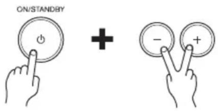
Note that resetting the controller will delete your custom settings.
Power
- Can’t turn on the controller
Make sure that the power cord is properly plugged into the wall outlet.
Unplug the power cord from the wall outlet, wait 10 seconds or more, then plug it in again.
■The controller turns off unexpectedly
The controller will automatically enter standby mode when Auto Standby launches.
■The controller turns off and after restoring the power, it turns off again
The protection circuit has been activated. Remove the power cord from the wall outlet immediately. Make sure that all speaker cables and input sources are properly connected, and leave the controller with its power cord disconnected for 1 hour. After that, reconnect the power cord and turn the power on. If the controller turns off again, unplug the power cord and contact your Onkyo dealer.
WARNING
If smoke, smell or abnormal noise is produced by the controller, unplug the power cord from the wall outlet immediately and contact your Onkyo dealer.
Audio
There's no sound, or it's very quiet
| Make sure that all audio connecting plugs are pushed in all the way. | 15 |
| Make sure that the input of TV is connected properly. | 15 |
| Make sure that the polarity of the speaker cables is correct, and that the bare wires are in contact with the metal part of each speaker terminal. | 14 |
| Make sure that the speaker cables are not shorting. | 14 |
| When the ON/STANDBY LED flashes white, the muting is enabled. Press 📋 on the remote controller or the Volume −/+ buttons simultaneously on the controller to disable the muting. | 18 |
| Make sure that none of the connecting cables are bent, twisted, or damaged. | — |
The subwoofer produces no sound
| Make sure that there is no obstacle or reflection between the controller and the subwoofer. | — |
| Make sure that the pairing the controller and the subwoofer completes normally. | — |
Noise can be heard
| Using cable ties to bundle audio cables with power cords, speaker cables, and the like may degrade the audio performance, so refrain from doing it. | — |
| An audio cable may be picking up interference. Try repositioning your cables. | — |
Remote Controller
The remote controller doesn't work
| Make sure that the battery is installed with the correct polarity. | 8 |
| Make sure that the remote controller is not too far away from the controller, and that there’s no obstruction between the remote controller and the controller’s remote control sensor. | 8 |
| Make sure that the controller is not subjected to direct sunshine or inverter-type fluorescent lights. Relocate if necessary. | — |
| If the controller is installed in a rack or cabinet with colored-glass doors, the remote controller may not work reliably when the doors are closed. | — |
The controller and the TV operated by your TV remote controller doesn't work
| Make sure that the controller mounted to the wall and the TV set are not placed too far. | 11 |
| Your TV remote controller might not be compatible with TV remote controller preprogrammed codes function. If the ON/STANDBY LED does not flash by pressing the buttons on your TV remote controller, use the supplied remote controller or program the controller. If the controller cannot be operated with your remote controller even if the programming has been performed, the controller might not recognize your remote controller. In this case, use the supplied remote controller. | — |
Volume +/- or Muting function works by also pressing other buttons when operating controller with your TV remote controller
| For some TV remote controller,Volume +/- or Muting function might work by also pressing other buttons.(Volume is increased by pressing 0(number button), etc.) To avoid this,program the controller with Volume +/-or Muting button function on your TV remote controller. |
Others
■ Standby power consumption
When the Auto Power On function is set — to “on”, the power consumption in ready mode may reach up to a maximum of 4 W.
■ Pairing the controller and the subwoofer
Turn on the controller before performing a pairing.
1 Press and hold LINK on the rear panel of the subwoofer for five seconds.
Flashing speed of the LINK LED is changed.
2 Press and hold ⏻ON/STANDBY on the controller for three seconds until the ON/STANDBY LED flashes white.
The controller and the subwoofer starts pairing. The ON/STANDBY LED flashes white twice indicating that the pairing is completed.
Tip
- If the controller is turned off or enters the standby mode, also the subwoofer enters the standby mode in 30 seconds. In this mode, the controller automatically detects a pairing point and reconnects. The subwoofer is automatically turned on when the link is recovered.
Note
- Depending on the reception condition, the sound might be stopped or interrupted while using. This is not a malfunction. In this case, change the place or direction of the controller or the subwoofer.
- If the controller and the subwoofer are too far, the reception might be unstable. They should be placed within 32 ft. (10 m).
- If there is an obstacle (metal door, concrete wall and insulation contained aluminum foil, etc.) between the controller and the subwoofer, it might block the reception and stop the sound. Place the controller and the subwoofer in good visibility with each other.
The controller contains a microcomputer for signal processing and control functions. In very rare situations, severe interference, noise from an external source, or static electricity may cause it to lockup. In the unlikely event that this happens, unplug the power cord from the wall outlet, wait at least five seconds, and then plug it back in.
Onkyo is not responsible for damages (such as CD rental fees) due to unsuccessful recordings caused by the unit's malfunction. Before you record important data, make sure that the material will be recorded correctly.
Before disconnecting the power cord from the wall outlet, set the controller to standby.
Specifications
Controller (LAP-301)
Rated Output Power
All channels: (North American)
20 watts minimum continuous power per channel, 4 ohm loads,
2 channels driven at 1 kHz, with a maximum total harmonic distortion of 0.8% (FTC) (Others)
2 ch × 20 W at 4 ohms, 1 kHz,
2 ch driven of 0.8% (IEC)
Maximum Effective Output Power
(Australian)
2 ch × 22 W at 4 ohms, 1 kHz,
2 ch driven (JEITA)
THD+N (Total Harmonic Distortion+Noise)
0.8% (Power Rated)
0.2% (1 kHz, 1 W)
Damping Factor 20 (Front, 1 kHz, 8 Ω)
Input Sensitivity and Impedance (Unbalance)
200 mV/47 kΩ (LINE)
Frequency Response
50 Hz - 20 kHz/+3 dB, -3 dB
(DIGITAL)
Signal to Noise Ratio
93 dB (DIGITAL, IHF-A)
Speaker Impedance
4 -8
Power Supply (North American)
AC 120 V, 60 Hz
(European) AC 230 V, 50 Hz
(Others) AC 220 - 240 V, 50/60 Hz
Power Consumption
*Listed on a label on the bottom
17.8 W
No-sound Power Consumption
(North American and European)
6 W
(Others) 6.1 W
Stand-by Power Consumption
(North American) 0.38 W
(European) 0.46 W
(Others) 0.47 W
Dimensions (W× H× D)
187 mm × 32 mm × 120 mm
7-3/8" × 1-1/4" × 4-3/4"
Weight 0.3 kg (0.7 lbs.)
Audio Inputs
Digital Optical: 1 Coaxial: 1
Analog Stereo Input
∅ 3.5 mm mini
Audio Output
Speaker Output SPEAKER OUT
Others
Wireless Subwoofer
1
Front Speaker (SLM-301)
Type Full Range Closed Box
Impedance 4 Ω
Maximum input power
20 W
Output sound pressure level
86 dB/W/m
Frequency Response
200 Hz - 20 kHz
Cabinet capacity 0.6 L (0.021 cubic feet)
Dimensions (W× H× D)
169 mm × 78 mm × 108 mm
6-5/8" × 4-3/8" × 5-1/4"
(incl. grille and projection)
Weight 0.7 kg (1.5 lbs)
Drivers unit 6.5 cm (2-1/2") cone
Terminal Spring type
Other Non magnetic shielding
Subwoofer (SLW-301)
Rated Output Power (FTC)
(North American)
50 watts minimum continuous
power, 4 ohms, driven at 100 Hz with
a maximum total harmonic distortion
of 1%
Rated Output Power (IEC)
(Others)
50 watts minimum continuous
power, 4 ohms, driven at 100 Hz with
a maximum total harmonic distortion
of 1%
Play Frequency Band
40 Hz - 200 Hz (DIRECT)
Cabinet capacity 11.5 L (0.41 cubic feet)
Dimensions (W× H× D)
261 mm × 337 mm × 269 mm
10-1/4" × 13-1/4" × 10-9/16"
(incl. grille and projection)
Weight 5.8 kg (12.8 lbs)
Drivers unit 16 cm (6-1/2") cone
Power Supply (North American) AC 120 V, 60 Hz
(Others) AC 220 - 240 V, 50 Hz
Power Consumption
14.8 W
Other Non magnetic shielding
Auto standby
Specifications and features are subject to change without notice.
Memo
ONKYO
Onkyo Corporation
2-1, Nisshin-cho, Neyagawa-shi, OSAKA 572-8540, JAPAN
Tel: 072-831-8023 Fax: 072-831-8163
http://www.onkyo.com/
Onkyo U.S.A. Corporation
18 Park Way, Upper Saddle River, N.J. 07458, U.S.A.
Tel: 800-229-1687, 201-785-2600 Fax: 201-785-2650
http://www.us.onkyo.com/
Onkyo Europe Electronics GmbH
Liegnitzerstrasse 6, 82194 Groebenzell, GERMANY
Tel: +49-8142-4401-0 Fax: +49-8142-4208-213
http://www.eu.onkyo.com/
Onkyo Europe Electronics GmbH (UK Branch)
The Coach House 81A High Street, Marlow, Buckinghamshire, SL7 1AB, UK
Tel: +44-(0)1628-473-350 Fax: +44-(0)1628-401-700
Onkyo China Limited
Unit 1033, 10/F, Star House, No 3, Salisbury Road, Tsim Sha Tsui Kowloon, Hong Kong.
Tel: 852-2429-3118 Fax: 852-2428-9039
http://www.onkyochina.com/
Onkyo China PRC
1301, 555 Tower, No.555 West NanJin Road, Jin an, Shanghai,
China 200041, Tel: 86-21-52131366 Fax: 86-21-52130396
http://www.cn.onkyo.com/
- WARNING:
- CAUTION:
- WARNING
- AVIS
- Important Safety Instructions
- Precautions
- Caution
- Never Touch this Unit with Wet Hands—
- Handling Notes
- For U.S. models
- FCC/IC Information for User IMPORTANT NOTE:
- REMARQUE IMPORTANTE :
- NOTE:
- IMPORTANT
- For European Models
- Use with a TV set
- Input Signal Warning
- Package Contents
- Features
- Sound System Controller
- Subwoofer
- Front Speakers
- DOLBY DIGITAL
- Bluetooth
- ■Using the Remote Controller
- ■Replacing the Battery
- Note
- Getting to Know the LS3100
- Top Panel (LAP-301)
- Rear Panel (LAP-301)
- Front Speakers (SLM-301)
- Subwoofer (SLW-301)
- Remote Controller
- Using your TV remote controller
- Tip
- Placement
- Mounting the Controller
- ■ Wall mounting
- Mounting/Placing the Front Speakers
- ■ Using the rubber stoppers for a more stable platform
- ■Attaching the stand
- ■Adjusting the angle
- ■Fixing the front speakers to prevent a falling accident
- Placing the Subwoofer
- ■Using the rubber stoppers for a more stable platform
- Connections
- Connecting the Front Speakers
- Speaker Connection Precautions
- Using the Subwoofer
- About TV Connections
- Cables and Jacks
- ■Optical digital audio
- Coaxial digital audio
- Connecting to the TV
- Connecting the Power cord
- (LAP-301)
- (SLW-301)
- Operations
- Turning On the controller
- Enjoying the sound
- Adjusting the Subwoofer Level
- Press SUBWOOFER +/- on the remote controller.
- Muting the controller
- ■Operating with the remote controller
- Press
- ■Operating on the controller
- Simultaneously press and hold the Volume -/+ buttons on the top panel.
- Setting the Auto Power On
- Turn off the controller.
- Press and hold ⏻ON/STANDBY on the top panel for three seconds.
- Press and hold ⏻ON/STANDBY on the top panel for three seconds again to turn the Auto Power On function “off”.
- Default: Ready (North American models), Standby (European and Australian models)
- About the Auto Standby function
- Using the Sound Modes
- Selecting Sound Modes
- SOUND MODE button
- Listening to an audio from Bluetooth device
- Press the TV input button on the top panel repeatedly or INPUT on the remote controller until the Bluetooth LED lights to select the Bluetooth selector.
- While the Bluetooth LED is flashing (25 seconds), you can operate the Bluetooth-enabled device to pair with the controller within a 32 ft. (10 m) range.
- Once the controller is detected and its name “Onkyo LS3100” appears on the display of your Bluetooth-enabled device, select the “Onkyo LS3100”. If a prompt requests a password (PIN code), key in the “0000”.
- Start playback on your device. The controller automatically starts playing the audio.
- Programming the controller for use of existing remote controller
- Settable button operation
- Setting the button operation
- Troubleshooting
- Power
- - Can’t turn on the controller
- ■The controller turns off unexpectedly
- ■The controller turns off and after restoring the power, it turns off again
- Audio
- Others
- ■ Standby power consumption
- ■ Pairing the controller and the subwoofer
- Press and hold LINK on the rear panel of the subwoofer for five seconds.
- Press and hold ⏻ON/STANDBY on the controller for three seconds until the ON/STANDBY LED flashes white.
- Specifications
- Controller (LAP-301)
- Rated Output Power
- Maximum Effective Output Power
- THD+N (Total Harmonic Distortion+Noise)
- Input Sensitivity and Impedance (Unbalance)
- Frequency Response
- Speaker Impedance
- Power Consumption
- No-sound Power Consumption
- Stand-by Power Consumption
- Audio Inputs
- Analog Stereo Input
- Audio Output
- Front Speaker (SLM-301)
- Rated Output Power (FTC)
- (North American)
- Rated Output Power (IEC)
- (Others)
- Play Frequency Band
- Dimensions (W× H× D)
- Memo
- ONKYO
Brand : ONKYO
Model : LS-3100B
Category : Home Theater