HM-Sec-Win - Remote control EQ-3 - Free user manual and instructions
Find the device manual for free HM-Sec-Win EQ-3 in PDF.

User questions about HM-Sec-Win EQ-3
0 question about this device. Answer the ones you know or ask your own.
Ask a new question about this device
Download the instructions for your Remote control in PDF format for free! Find your manual HM-Sec-Win - EQ-3 and take your electronic device back in hand. On this page are published all the documents necessary for the use of your device. HM-Sec-Win by EQ-3.
USER MANUAL HM-Sec-Win EQ-3
text_image
HomeMaticMontage- und Bedienungsanleitung (S. 2) Mounting instruction and operating manual (p. 33)
WinMatic Funk-Fensterantrieb: WinMatic Radio-controlled window drive: HM-Sec-Win
Printed in Hong Kong
text_image
A B C D E V1 V2WinMatic:
A – Antriebsstange
natural_image
Pure technical line drawing of a mechanical part with dashed lines indicating hidden edges (no text or symbols)text_image
Technical diagram of a mechanical device with labeled components A and C, showing internal components and directional arrows.text_image
60.00 65.00 A B6.2.5 Montage Halteplatte
text_image
Technical diagram of a vertical electrical cabinet with labeled components and a directional arrow indicating movement or force.natural_image
Technical line drawing of a vertical mechanical device with labeled component A, showing internal components and mounting holes (no text or symbols beyond label)natural_image
Technical line drawing of a mechanical assembly with no visible text or symbolsnatural_image
Technical line drawing of a mechanical linkage or support structure (no text or symbols)natural_image
Technical line drawing of a vertical industrial machine with control panel and fan (no text or symbols)7 Inbetriebnahme
natural_image
Simple line drawing of a circular object with four small floating devices on top, enclosed in a rectangular frame (no text or symbols)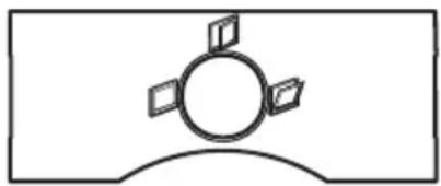
natural_image
Simple line drawing of a circular object with four small floating cards on top, enclosed in a curved base (no text or symbols)natural_image
Simple line drawings of a vertical panel and a folded folder (no text or symbols)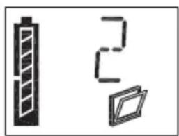
natural_image
Three simple icons: a battery, a vertical bar, and a stylized document (no text or symbols)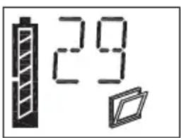
text_image
29text_image
Diagram showing three labeled boxes with percentage indicators above, likely representing storage or data storage levels.natural_image
Technical line drawing of a mechanical assembly with no visible text or symbols- English edition 10/2008
Documentation © 2007 eQ-3 Ltd., Hong Kong
All rights reserved. No parts of this manual may be reproduced or processed in any form using electronic, mechanical or chemical processes in part or in full without the prior explicit written permission of the publisher.
It is quite possible that this manual has printing errors or defects. The details provided in this manual are checked regularly and corrections are done in the next edition. We do not assume any liability for technical or printing errors. All registered trade marks and copyrights are acknowledged.
Printed in Hong Kong.
We reserve the right to make changes due to technical advancements without prior notice.
73472/V1.1
Contents
1 Information about these instructions .... 36
2 Hazard Information .... 36
3 Function 37
3.1 Brief overview.... 37
3.2 Scope of supply 40
4 General system information on HomeMatic 40
5 General information on radio operation 40
6 Mounting 41
6.1 Overview....41
6.2 Performing mounting 41
6.2.1 Measuring the maximum tilt range 41
6.2.2 Preparing WinMatic for the appropriate mounting side....42
6.2.3 Removing the window handle 43
6.2.4 Preparing the mounting position for the toothed rack holder ..... 44
6.2.5 Mounting the retaining plate 45
6.2.6 Mounting the toothed rack holder....46
6.2.7 Mounting the toothed rack and battery pack....48
7 Start-up. 49
7.1 Adapting the window actuator to the window used....49
7.1.1 Setting the mounting side for the window turning handle ..... 50
7.1.2 Pulling force of the tilt actuator....51
7.1.3 Maximum tilt range 52
7.2 Teaching-in remote controls and buttons in two steps ..... 5 3
7.2.1 Overview....53
7.2.2 First teach-in step - (Pure) teaching-in (no parameters) 54
7.2.3 Second teach-in step - Setting parameters 55
7.3 Teaching-out remote controls 56
8 Operation 56
8.1 Local operation on the device 56
8.2 Opening the window fully 57
8.3 Operation via taught-in control elements ..... 57
8.3.1 Closing and tilting 57
8.3.2 Increasing the travel speed during motion 57
8.4 Information on the device display 58
8.4.1 Display of the most recently used control unit....58
8.4.2 Display when executing profiles 58
8.5 Standby operation....58
8.6 Overview of how WinMatic and taught-in control elements behave, depending on the mode and the buttons pressed on the control element. Behaviour of a transmitter not yet taught-in ..... 59
9 Messages and error messages 61
9.1 Battery empty....61
9.2 Mechanical error 61
10 Resetting to the initial state. 61
11 The WinMatic battery pack 62
12 Maintenance and cleaning 62
13 Technical data 63
1 Information about these instructions
Read these instructions carefully before beginning operation with your
HomeMatic components.
Keep the instructions handy for later consultation!
Please hand over the operating manual as well when you hand over the device to other persons for use.

Attention! This indicates a hazard.

Note. This section contains additional important information!
2 Hazard Information

WinMatic is a technical system which can fail due to various factors.
You should, therefore, take the following notes into account when using the device:

Do not use WinMatic on windows and doors that serve as escape routes.
Caution! Important instruction for safe mounting.
Before mounting the window actuator, check that it is in perfect condition.
Check that all the mounting accessories supplied are complete and in good working order.
Make sure that foreign bodies cannot become embedded between the casement and the window frame.
After mounting, check that WinMatic is functioning correctly.
WinMatic is not suitable for round arched, segmental
arched or angled windows.
Other notes:
As fixing screws are used to mount WinMatic, there is a possibility that the casement may become damaged during this process. For rented accommodation, therefore, there is a risk that a landlord may make a claim for compensation or hold back the tenant's deposit.
In the context of product liability for the WinMatic system itself, eQ-3 AG does not accept any liability for consequential damage resulting from actual use of the product, e.g. for damage caused to a window, etc.
Caution! Notes on safe operation
When the casement is moving, particularly during automatic closing, do not put your hands between the frame and the moving casement.
Young children must not operate WinMatic unsupervised. When using WinMatic, particularly when integrating it into system-wide automatic control systems, children and pets should be supervised at all times (due to the risk of trapping and injuring body parts).
The device may only be operated indoors and must be protected from the effects of damp and dust, as well as solar or other methods of heat radiation.
WinMatic battery pack:
Do not throw the battery pack into a fire.
Caution! There is a risk of explosion if the battery is not replaced correctly.
Never short-circuit battery connecting terminals.
Only charge the battery pack with the plug-in main adapter belonging to WinMatic.
3 Function
3.1 Brief overview
WinMatic can be used on conventional tilting or tilt and turn windows.
The window handle is replaced by WinMatic, which actuates the window fittings and their locking points (a process that is usually performed by the window handle). WinMatic tilts the casement by means of a curved toothed rack that is connected to the window frame.

WinMatic is not suitable for round arched, segmental arched or angled windows.
The window is locked, unlocked and tilted wirelessly (868.3 MHz) from inside and outside.
From inside, you can operate the actuator using the buttons available on it.
The window can be operated manually by disengaging the toothed rack and turning the hand wheel.
Both the hand-held transmitter and the window actuator are battery-powered, so there is no need for a mains power supply near to the window.
The window actuator features a liquid crystal control display that is used for programming and also shows status messages during standard operation. This means that the operator is always aware of the device status.
In order to maintain a high degree of system availability, clear warnings are given in good time to indicate that a battery pack is almost empty.
Unambiguous display symbols and a plain text display ensure that the user retains a clear overview of all statuses during configuration and operation.
text_image
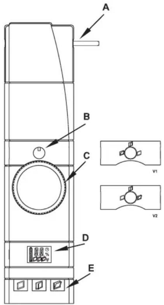
A B C D E v1 v2WinMatic:
A - Actuator rod
B - Position indicator for the window turning handle
C - Hand wheel
D - Device display
E - Control buttons
V1/V2 - Masking frames with position indicator for the window turning handle
text_image
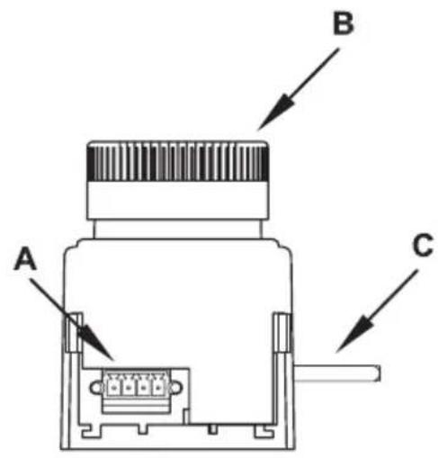
A B CWinMatic (view from below):
A – Socket for battery pack
B - Hand wheel
C - Actuator rod
text_image
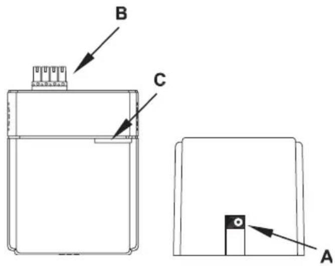
B C AWinMatic battery pack:
A - Connection for plug-in main adapter
B - Plug connector for connecting to WinMatic
C - Device LED
3.2 Scope of supply
• Wireless window actuator
- Mounting plate
• 2 screws M5 x 35 mm
• 4 self-tapping screws (3.5 x 20 mm)
• Toothed rack with fixing accessories
• 3 handle axles of various lengths
• Masking frames with position indicator for the window turning handle
• WinMatic battery pack
• Plug-in main adapter
• Installation and operating manual
4 General system information on HomeMatic
This device is a part of the HomeMatic home control system and works with the bidirectional BidCoS® wireless protocol.
All devices are delivered in a standard configuration. The functionality of the device can also be configured with a programming device and software.
The additional functions that can be made available in this way and the supplementary functions provided by the HomeMatic system when it is combined with other components are described in the separate Configuration Instructions and in the HomeMatic System Manual.
All current technical documents and updates are provided at www.HomeMatic.com.
5 General information on radio operation
The radio transmission is on a non-exclusive transmission path which means that there is a possibility of interference occurring. Interference can also be caused by switching operations, electrical motors or defective electrical devices.

The range of transmission within buildings can greatly deviate from open air distances. Besides the transmitting power and the reception characteristics of the receiver, environmental influences such as humidity in the vicinity and local structures also play an important role.
eQ-3 Entwicklung GmbH hereby declares that this device conforms with the essential requirements and other relevant regulations of Directive 1999/5/EC.
The full declaration of conformity is provided at www.HomeMatic.com.
6 Mounting
6.1 Overview
Please read this entire section before starting to carry out the mounting procedure.
Before mounting, you must check that the window is correctly adjusted, that the window fittings move smoothly and that they close properly. If necessary, seek the assistance of an expert to readjust the window. Once mounted, the
WinMatic cannot be repositioned on the window.
Mounting is performed in several steps.
An initial overview of the entire mounting process is given below. To adapt the WinMatic parameters to the window being used, the toothed rack and the handle axle will have to be removed.
- Measure the window's maximum tilt range (you will need this in order to set the maximum tilt range such that it will still be possible to disengage the toothed rack).
• Prepare WinMatic for the appropriate mounting side (may not be necessary). - Remove the handle from the window.
• Prepare the mounting position for the toothed rack holder.
• Mount the WinMatic retaining plate.
• Mount the toothed rack holder.
After that, start-up can be performed as described in the next section.
6.2 Performing mounting
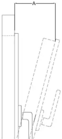
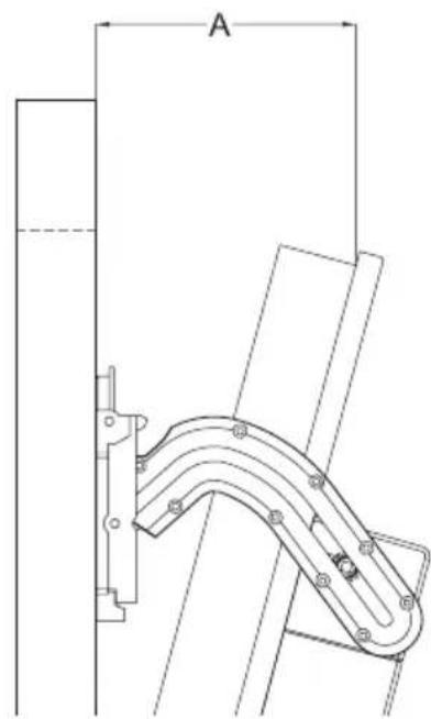
6.2.1 Measuring the maximum tilt range
Move the window into its tilt position.
Measure the maximum tilt range (A), which is the gap between the casement and the frame, using a metric ruler.
natural_image
Pure technical line drawing of a mechanical part with dashed lines indicating hidden edges (no text or symbols)6.2.2 Preparing WinMatic for the appropriate mounting side
If required, prepare WinMatic for the appropriate mounting side. In its initial state, WinMatic is ready for mounting on windows that are hinged on the right.
To convert WinMatic for mounting on a window that is hinged on the left (window handle on the right), proceed as described below.
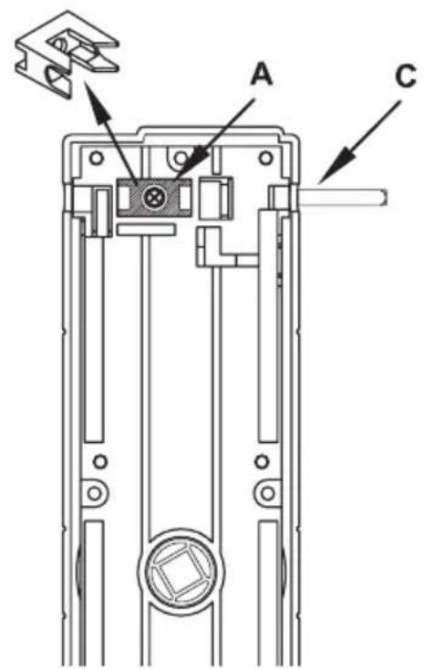
text_image
Technical diagram of a mechanical device with labeled components A and C, showing internal structure and mounting points.Remove the screw from the shaft locking device (A), followed by the shaft locking device itself.
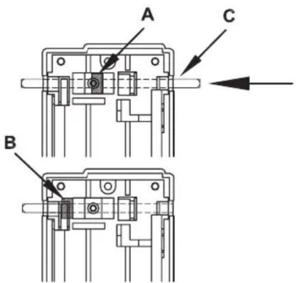
text_image
A C BPush the shaft (C) in the direction of the arrow as far as it will go. The shaft stopper (B) is now on the other side of the shaft locking device. Reinsert the shaft locking device and fix it in place again with its screw.
6.2.3 Removing the window handle
Move the window handle to the "open" position (horizontal).
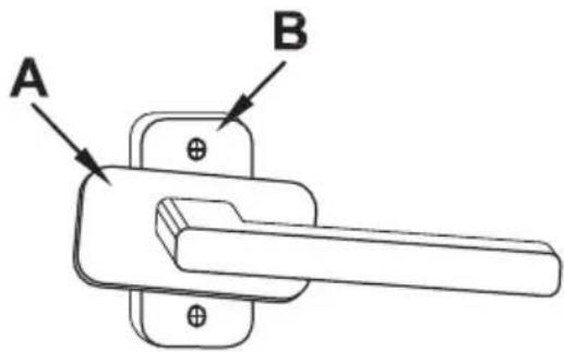
text_image
A BTurn the handle cover (A) to the side in order to gain access to the fixing screws (B).
Loosen and remove the screws.
text_image
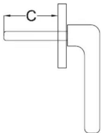
CNow measure the length of the window handle axle (C) in order to select the correct handle axle from those supplied with WinMatic.
6.2.4 Preparing the mounting position for the toothed rack holder
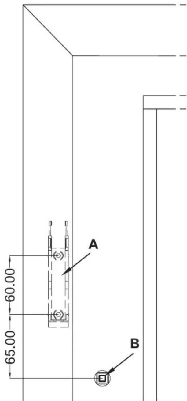
Clean the area of the window frame around the handle (to ensure that the toothed rack holder will stick to the frame properly if adhesive is to be used for mounting). Mark the mounting position (height) of the toothed rack holder in accordance with the diagram below (which is for a window hinged on the right). The exact position is defined once WinMatic has been mounted.
text_image
60.00 65.00 A B6.2.5 Mounting the retaining plate
Use the screws supplied (M5 x 35 mm) to fix the retaining plate.
Make sure that the retaining plate is aligned parallel to the frame. Align the plate as per the diagram with the longer piece underneath the hole for the window turning handle. Use the holes for fixing the window handle (B) to do this.
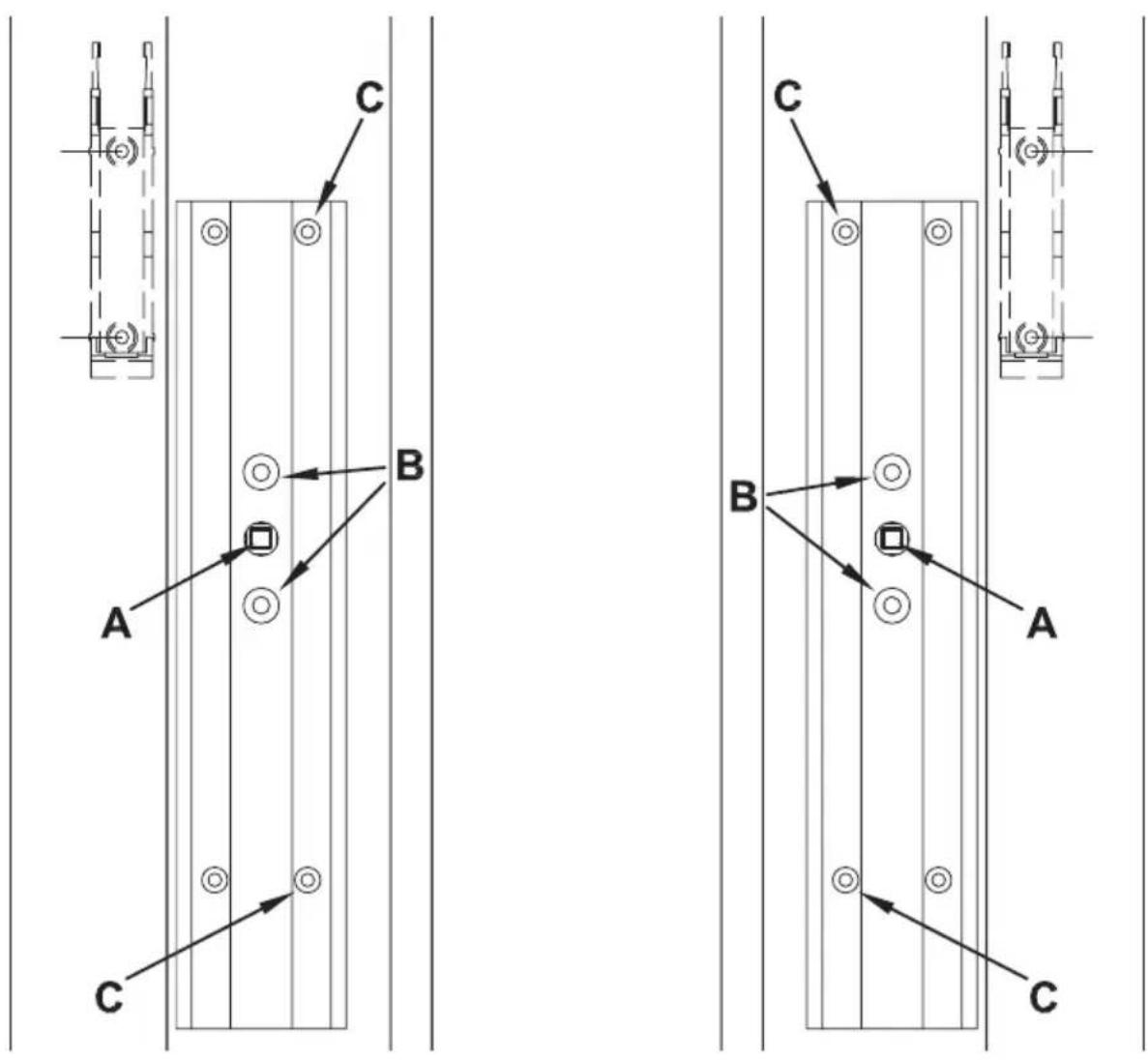
If necessary, you can also use the self-tapping screws supplied (3.5 x 20 mm) to fix the retaining plate in position. If you do so, only use the holes on the side facing towards the window glass (C in the two diagrams).
If the self-tapping screws are used to fix the retaining plate, this will damage the casement. For those living in rented accommodations, this could lead to a landlord making a claim for compensation or holding back a tenant's deposit.
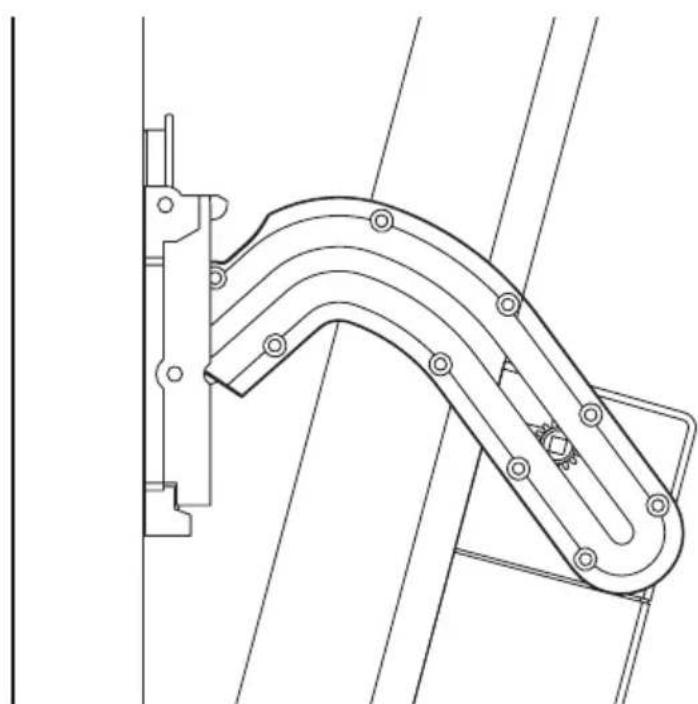
6.2.6 Mounting the toothed rack holder
Slide WinMatic onto the mounting plate from above, in the direction of the arrow (1).
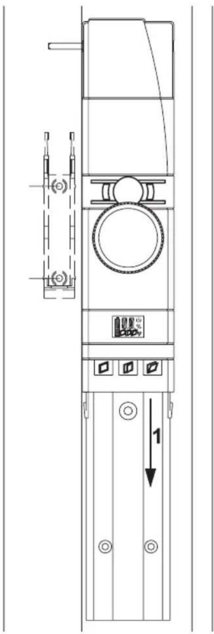
text_image
Technical diagram of a vertical electrical cabinet with labeled components and a directional arrow indicating movement or force.Check the position of the toothed rack holder that is marked on the window frame. Do not attach the pinion just yet. Make any necessary minor adjustments to the mounting position.
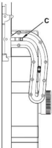
natural_image
Technical line drawing of a mechanical assembly with a curved pipe and labeled component C (no text or symbols beyond label)Adjust the mounting height of the holder so that, when the window is closed, initial travel in the toothed rack is in the horizontal plane.
When mounting the holder, you must also ensure that the lateral gap (A) between the holder and the casement is such that the casement can still move freely. Do not make the gap so large that the shaft cannot reach far enough into the pinion.

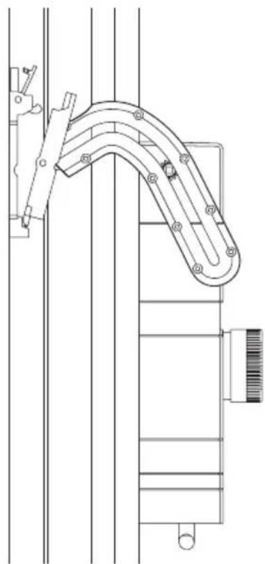
natural_image
Technical line drawing of a vertical mechanical device with labeled component A (no text or symbols beyond label)If necessary, now mark a better mounting position for the toothed rack holder. Release the toothed rack from the holder and use adhesive strips or the self-tapping screws supplied to fix the holder in place.
If the self-tapping screws are used to fix the holder, this will damage the
casement. For those living in rented accommodation, this could lead to a landlord making a claim for compensation or holding back a tenant's deposit.
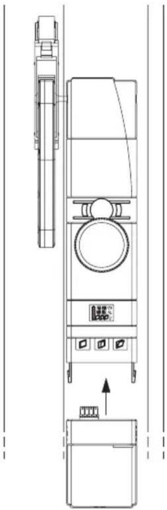
6.2.7 Mounting the toothed rack and battery pack
Attach the toothed rack and pinion to the shaft.
natural_image
Technical line drawing of a mechanical assembly with no visible text or symbolsFix the toothed rack in the holder and click it into place.
natural_image
Technical line drawing of a mechanical linkage or support structure (no text or symbols)Insert the battery into WinMatic from below.
natural_image
Technical line drawing of a vertical industrial machine with control panel and fan (no text or symbols)7 Start-up
7.1 Adapting the window actuator to the window used
Please read this entire section before starting to make settings.
Set-up mode is used to make parameter settings, which are determined by the properties of the window:
• Mounting of WinMatic on the left or right
- Pulling force
• Maximum tilt range
The set-up process is executed in stages.
Press the “close” and “open” buttons simultaneously for longer than four seconds to enter (or exit) set-up mode.
If a master remote control has not yet been taught-in, you will enter set-up mode directly.
However, if a master remote control has already been taught-in, the display first shows an "X". You then have three minutes to press a button on the master remote control in order to enter set-up mode; if you do not do this in time, the process will be cancelled. If no actions are executed in set-up mode for three minutes, the mode will be exited.
In set-up mode, the three buttons are assigned as follows:
"Close" button: "-"
"Open" button: "+"
“Tilt” button (when pressed for longer than four seconds): Confirm entry and move on after the last step, confirming the final entry will result in set-up mode being exited. If no entries are made for three minutes, set-up mode will be exited automatically.

No operations can be performed whilst set-up mode is active.
If an error occurs or an incorrect operation is executed, set-up mode is cancelled.
7.1.1 Setting the mounting side for the window turning handle

When launching the set-up mode, the window must be open, the handle axle must be removed and the toothed rack must be disengaged.
The display indicates the handle or mounting side by means of “mR” for right-hand mounting or “mL” for left-hand mounting. Select the mounting side using + (right) or - (left).
Whilst settings are being made, the tilt actuator's motor is active.
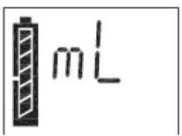
text_image
mL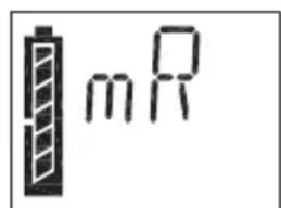
text_image
mRConfirm the entry by pressing and holding the "tilt" button (for longer than four seconds).
| Hinged side | Handle position/WinMatic mounting position | Setting |
| Left | Right mR | |
| Right | Left mL |
After a certain period (the display shows a countdown with the “clock” symbol), the tilt actuator stops and WinMatic moves the handle axle to the “open window” position. The “window open” symbol flashes.
When the “window open” symbol is displayed continuously and the “window tilted” symbol flashes, this indicates that this procedure is complete.
Now insert the handle axle, with the indicator pointing up.

Three handle axles of various lengths are supplied with WinMatic. Select the longest possible axle that can be properly mounted. When selecting your handle axle, refer to the length of the axle of the window handle that has been removed.
Some force may be required to push in the appropriate handle axle, once you have chosen it.
Now mount the correct masking frame with position indicator for the window turning handle.
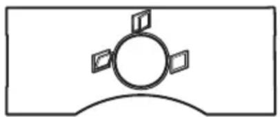
natural_image
Simple line drawing of a circular object with four small rectangular elements on top, no text or symbols present.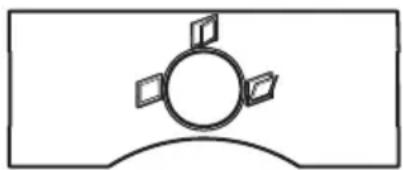
natural_image
Simple line drawing of a circular object with four small rectangular elements on top, enclosed in a rounded rectangle (no text or symbols)Figure: Masking frame for WinMatic mounted on the left and on the right
Press the window shut and then move it to the “tilt” position. To do this, use the hand wheel (press down and turn) to set the rotary actuator such that the “window tilted” symbol is displayed continuously.

Check that the window really is in the “tilt” position. If the window is still in the “open” position, the handle
axle being used is too short.
Then attach the toothed rack and click it into place.

Before confirming with the “tilt” button (long button press), make sure that the “window tilted” symbol is still shown
on the display.
7.1.2 Pulling force of the tilt actuator
At first, WinMatic pulls the casement with the lowest force that can be set. You can increase or decrease the pulling force using the +/- buttons. Each time you make a new setting, you can test it by pressing button 3 briefly and then increase/decrease the pulling force, if necessary. There are 6 levels that are indicated on the display.
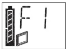
text_image
F1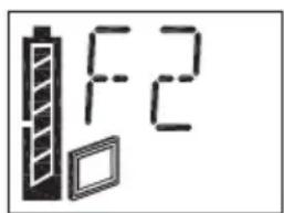
text_image
F2Confirm your setting by pressing and holding the “tilt” button (for longer than four seconds).

Initially, the pulling force can be left at value 1. If the casement is heavy or the window is subject to a strong wind, you can increase the force in stages. The force must be large enough to enable the casement to be closed completely and locked effortlessly. To change the setting, simply call up setup mode again.

If you are using double-sided adhesive tape to fix the toothed rack holder in place, the pulling force must be left at value 1. If the force is increased, this will damage the adhesive bond.
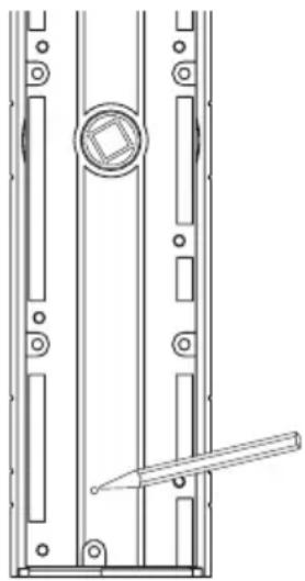
7.1.3 Maximum tilt range
You can increase or decrease the maximum tilt range using the +/- buttons. Each time you make a new setting, you can test it by pressing the “tilt” button briefly and then modify it, if necessary. There are 29 levels that are indicated on the display.

The maximum possible tilt range that has been measured should not be set as the maximum tilt range (A); instead, a lower value should be used so that the toothed rack can be disengaged easily.
natural_image
Technical line drawing of a mechanical component with labeled dimension A (no text or symbols present)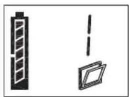
natural_image
Simple line drawings of a vertical panel and a rectangular box, no text or symbols present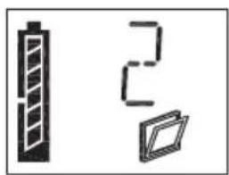
natural_image
Three simple icons: a vertical battery, a stylus with the number 2, and a folded document (no text or symbols)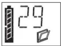
text_image
29Confirm your setting by pressing and holding the "tilt" button (for longer than four seconds). Set-up mode is then exited.
7.2 Teaching-in remote controls and buttons in two steps
7.2.1 Overview
Please read this entire section before starting to carry out the teach-in procedure.
Teaching-in:
If WinMatic has already been taught-in to a HomeMatic central control unit, direct

teach-in on the device will no longer be possible. When teach-in mode is called in such cases, the display will briefly show "Xc" and the call-up procedure will be cancelled. Additional teach-in procedures must then be carried out via the central control unit. For more information on this, please refer to the documentation relating to the HomeMatic central control unit and to the HomeMatic system manual.

The teach-in procedure that does not use a central control unit is described below. When using WinMatic, one remote control serves as a safety-relevant component and is designated as the “master” remote control – this remote control is automatically the first one to be taught-in. From now on, a button on the master remote control must always be pressed in order to authenticate all other teach-in procedures.

Do not pass the “master” remote control on to anyone and do not use it for everyday operation. If the master remote control is lost, a different remote control can only be taught-in as the new master by resetting to the initial state.
Teaching-in is divided into two steps:
- Teach-in mode: Teaching-in the remote control with default value (open/close)
- Configuration mode: Setting parameters (optional)

Configuration mode is not called up automatically after teaching-in; instead, it must be selected explicitly.
- Calling teach-in mode: Long button press on "close" (for longer than four seconds)
- Calling configuration mode: Long button press on "open" (for longer than four seconds)
Both modes are exited in the same way.
Setting parameters:
In configuration mode, you can set parameters for the taught-in buttons.
The following settings can be made:
- Dwell time in the “tilted” state (how long the window should remain tilted for)
- % value for the tilt range (relating to the maximum possible tilt range set for the window)
- Tilting/rotating travel speed during locking/unlocking
If a “close” button that has already been taught-in is pressed after configuration mode has been called up, only the following parameter can be set for the associated profile:
- Travel speed
When assigning parameters, the master remote control does not have to be used for authentication purposes. Instead, the parameters for buttons on the master remote control are set once those buttons are pressed.
Pairs of buttons on a remote control always behave in the same way: If the window is in motion, pressing the other button of the pair will cause it to stop. The “close” button always behaves in the same way, first stopping the opening movement and then closing the window.
7.2.2 First teach-in step - (Pure) teaching-in (no parameters)

If a master remote control has not yet been taught-in, you will enter teach-in mode directly and the remote control to be taught-in becomes the master remote control. However, if a master remote control has already been
taught-in, the display first shows an "X". You then have three minutes to press a taught-in button on the master remote control in order to enter teach-in mode; if you do not do this in time, the process will be cancelled.
To teach-in new control elements, put WinMatic in teach-in mode (long button press on “close”) and, if required, authenticate this step by pressing a button on the master remote control. If the antenna symbol on the WinMatic display flashes, this indicates that teach-in mode is active.
If no actions are executed in teach-in mode for three minutes, the mode will be exited.
Now press the teach-in button to initiate the teach-in procedure on the control element to be taught-in.
After that, press one button of the pair of buttons/the individual button (depending on the control element in question) to be taught-in. The pair of buttons/individual button is then taught-in as a close/tilt button with default values.
Teach-in mode is exited automatically following successful teaching-in.
"OK" appears briefly on the display by way of confirmation.

Note: In HomeMatic, control elements are defined as "OFF" or "ON" buttons as standard and, if required, grouped as an "OFF/ON" pair of buttons.
During teaching-in, the "OFF" button is assigned the "close" function and
the "ON" button the "tilt" function.
7.2.3 Second teach-in step - Setting parameters
Press and hold the “open” button (for longer than four seconds) to call up configuration mode (the mode is exited in the same way). If the antenna symbol flashes, this indicates that configuration mode is active.
Initially, the display shows "PE".
If the transmitter button to be configured, which has already been taught-in, is then pressed, „PE“ disappears and the parameters can be set.
Configuration mode is exited automatically following successful configuration or if no entries are made for around three minutes (“antenna” symbol disappears).
Every configuration value entered must be accepted by pressing and holding the "tilt" button. When you have done this, WinMatic jumps to the next value that can be configured.
Settings for an "open" button:
The dwell time in the “tilted” state can be set by modifying the value (--, 1 – 99 minutes); “close” button changes the tens digit and “open” button the units digit. The clock symbol is also displayed. The “--” value here means that there is no time restriction (i.e. infinitely long).
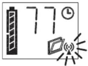
text_image
77Confirm the entry by pressing the "tilt" button (for longer than four seconds).
Next, enter the tilt angle (as a percentage of the maximum possible tilt angle); 0 – 100%. The percentage symbol is shown on the display, next to the antenna symbol.
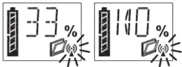
text_image
33 % 110 %Confirm the entry by pressing the "tilt" button (for longer than four seconds).
Finally, enter the travel speed as one of 9 levels: The display shows a "v" in the first space, followed by a digit (1 - 9).
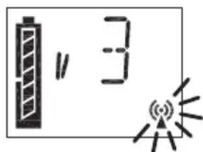
text_image
" 3Once you have confirmed this entry by pressing the "tilt" button (for longer than four seconds), configuration mode is exited.
You can configure the travel speed of the "close" button in the same way.
7.3 Teaching-out remote controls
Press the “open” and “close” buttons simultaneously for longer than four seconds (the mode is exited in the same way).
When teaching-out remote controls, the master remote control must be used for authentication purposes (as with teaching-in). You can use the “close” (-) and “open” (+) buttons to select the ID (2 – 20) of the remote control to be taught-out and confirm the teaching-out procedure by pressing the “tilt” button. The master remote control cannot be taught-out. If the master remote control is lost, WinMatic will have to be completely reset.
If only the master remote control is taught-in, "MA" appears on the display once teach-out mode has been called.
Teaching-out deletes all the profiles/links to a transmitter saved in WinMatic. If no entries are made for three minutes, teach-out mode will be exited automatically.
8 Operation
8.1 Local operation on the device
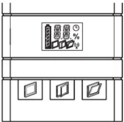
text_image
Diagram showing three labeled boxes with percentage indicators and a central icon, likely representing storage or data storage system.If WinMatic is in operator control mode (as is standard), direct operation is possible:
- "Close" button
- “Open” button
- “Tilt” button
If an operation is performed on the device, this is indicated on the device display by an “M” (manual operation).
8.2 Opening the window fully
If the window is to be opened fully, press the “open” button on the device. WinMatic then moves the handle axle to the “open” position. The “window open” symbol appears on the display. The position indicator for the window turning handle is also in the “open” position.
To fully open the casement, you must now disengage the toothed rack from the window frame.

When the window is open, remove the battery pack. This will prevent inadvertent operations being performed, which could result in the window being damaged.
8.3 Operation via taught-in control elements
8.3.1 Closing and tilting
When control elements have been taught-in, WinMatic can be operated wirelessly. Irrespective of the parameters set during teaching-in, only two types of motion are available in this instance:
- Closing and locking
• Tilting (by x% for n minutes)
In HomeMatic, control elements are defined as “OFF” or “ON” buttons as standard and, if required, grouped as an “OFF/ON” pair of buttons. During teaching-in, the “OFF” button is assigned the “close” function and the “ON” button the “tilt” function. You can stop a particular motion by pressing the button for the opposite type of motion.
8.3.2 Increasing the travel speed during motion
When a destination is approached, initially the speed stored in the profile is used. Pressing the same button again will increase the travel speed in stages, up to the maximum possible value.
Overview of operating behaviour:
| WinMatic position Button | press Behaviour | |
| Opening/unlocked | OPEN | Increase speed by 1 stage |
| Closing/locked | CLOSE | Increase speed by 1 stage |
| Opening/unlocked CLOSE | Stop | |
| Closing/locked OPEN Stop |
8.4 Information on the device display
8.4.1 Display of the most recently used control unit
During operation, the WinMatic display shows how WinMatic was accessed most recently:
1 Master remote control
2 - 20 Taught-in remote controls buttons
c Central control unit
M Direct operation on WinMatic
W Operation via wireless interface
8.4.2 Display when executing profiles
During motion, the symbol relating to the target state of that motion will always flash:
Close: window closed
Tilt: window tilted
Open: window open
If a profile with a set dwell time is active in the “tilted” state (and subsequent actions are expected), the “clock” symbol flashes.
Example:
Window should be tilted by 40% for 10 minutes:
When tilting is being performed the “window tilted” symbol flashes, as does the clock symbol, although the latter does not start to flash until “40%” is reached. During the subsequent closing motion, the “clock” symbol disappears.
8.5 Standby operation
If WinMatic does not respond when operated, the window can still be opened by hand. To do this, push the hand wheel backwards to disengage the actuator.

Depending on the error that has occurred, the actuator may still be subject to mechanical stress. If this is the case, more force will be needed to push the hand wheel in (and disengage the actuator).
8.6 Overview of how WinMatic and taught-in control elements behave, depending on the mode and the buttons pressed on the control element. Behaviour of a transmitter not yet taught-in:
| WinMatic Transmitter | Button pressed(transmitter) | Action | |
| - - - - | |||
| - - CLOSE - | |||
| - - OPEN - | |||
| Teach-in mode 1 | - CLOSE - | ||
| Teach-in mode 2 | - CLOSE - | ||
| Teach-in mode 1 | - OPEN - | ||
| Teach-in mode 2 | - OPEN - | ||
| - | Teach-in mode | CLOSE - | |
| - | Teach-in mode | OPEN - | |
| Teach-in mode 1 | Teach-in mode | CLOSE | Teach-in withdefault values following authentication viathe master |
| Teach-in mode 2 | Teach-in mode | CLOSE - | |
| Teach-in mode 1 | Teach-in mode | OPEN | Teach-in withdefault values following authentication viathe master |
| Teach-in mode 2 | Teach-in mode | OPEN - | |
Behaviour of a transmitter that has been taught-in (for teach-in mode 1, following authentication via the master):
| WinMatic Trans | mitter Button pressed Action | ||
| - - - - | |||
| - - CLOSE Execute profile | |||
| - - OPEN Execute profile | |||
| Teach-in mode 1 | - CLOSE - | ||
| Teach-in mode 2 | - CLOSE | Set/modify other WinMatic parameters without authentication via the master | |
| Teach-in mode 1 | - OPEN - | ||
| Teach-in mode 2 | - OPEN | Set/modify other WinMatic parameters without authentication via the master | |
| - | Teach-in mode | CLOSE - | |
| - | Teach-in mode | OPEN - | |
| Teach-in mode 1 | Teach-in mode | CLOSE | Teach-in with default values following authentication via the master |
| Teach-in mode 2 | Teach-in mode | CLOSE - | |
| Teach-in mode 1 | Teach-in mode | OPEN | Teach-in with default values following authentication via the master |
| Teach-in mode 2 | Teach-in mode | OPEN - | |
9 Messages and error messages
9.1 Battery empty
If a battery is almost empty, WinMatic signals this state by emitting three beeps on completing each motion.

The beep is also emitted for some time after the charger has been inserted and only stops when the battery reaches a defined minimum charge level.
9.2 Mechanical error
If a mechanical error (jamming or similar) is detected, one beep is emitted. It is then no longer possible to operate WinMatic using taught-in control elements (remote controls and buttons signal this state with the error message: "Command could not be executed.").
You can reset this state by performing one operation on WinMatic directly.
10 Resetting to the initial state
natural_image
Technical line drawing of a mechanical assembly with no visible text or symbolsReset button on the rear of WinMatic
On the rear of WinMatic is a button that can only be accessed when the unit has been dismounted. If you press this button for four seconds, the WinMatic display shows "R?". Pressing it for a further four seconds (at least) will then reset the unit to the initial state. The display briefly shows "--".
11 The WinMatic battery pack
The battery pack can be charged when the unit is mounted or dismounted. To charge the battery pack, connect the plug-in main adapter supplied with your WinMatic (the socket for the DC-plug is located underneath the battery pack). The battery pack's device LED indicates the charging condition (irrespective of whether the battery pack is attached to WinMatic or not).
| Device LED lights up red | Battery pack is being charged |
| Device LED lights up green | Battery pack is fully charged, trickle charge |
| Device LED is off | Plug-in main adapter not connected |
If the battery is fully discharged, it will take around 7 hours to charge up.

The full charging capacity (all battery segments visible on the WinMatic display) may not be reached until the battery has undergone several charge cycles.

Caution! Danger of explosion if battery is replaced improperly.
batteries are not to be disposed of with the household waste! We dispose them at your local battery collection point!
12 Maintenance and cleaning
The product does not require you to carry out any maintenance. Enlist the help of an

expert to carry out any maintenance or repairs. Clean the product using a soft, lint-free cloth that is clean and dry.
You may dampen the cloth a little with lukewarm water in order to remove more stubborn marks. Do not use any detergents containing solvents, as they could corrode the plastic housing and label.
Check that your product is safe from a technical point of view (that the housing is not damaged, for example) on a regular basis. If you have reason to believe that it is no longer safe to operate the device, put it out of service. Remove the battery pack to safeguard the device against unintentional operation.
Safe operation may no longer be possible if:
• The device shows signs of external damage
• The device no longer works
• The device has been stored for a long period in unfavourable conditions
• The device has been subjected to unfavourable transport conditions
13 Technical data
WinMatic:
Radio frequency: 868.3 MHz
Typ. open air range: 100 m
Power supply: battery pack (10.8 VDC)
Degree of protection: IP20
Housing: ABS
Housing colour: pure white, silver masking frame
Display: LCD 20 x 14 mm
(symbols and 14-segment display)
Dimensions: 319 x 59 x 80 mm (incl. battery/not incl. axles)
(H x W x D)
Weight: 770 g (not incl. battery pack)
1,110 g (incl. battery pack)
WinMatic battery pack:
Voltage: 10.8 VDC
Charging time
(fully discharged battery): Around 7 hours
Degree of protection: IP20
Housing: ABS
Housing colour: pure white
Dimensions: 75 x 59 x 80 mm
(H x W x D not incl. plug-in main adapter)
Weight: 340 g
Instructions for disposal
Do not dispose of the device as part of household waste! Electronic devices are to be disposed of in accordance with the guidelines concerning electrical and electronic devices via the local collection point for old electronic devices.

The CE sign is a free trade sign addressed exclusively to the authorities and does not include any warranty of any properties.

eQ-3 AG
Maiburger Straße 29
D-26789 Leer
www.eQ-3.com