RocketRAID 2320 - Contrôleur RAID Highpoint - Free user manual and instructions
Find the device manual for free RocketRAID 2320 Highpoint in PDF.


| Product Type | RAID Controller |
| Brand | Highpoint |
| Model | RocketRAID 2320 |
| Interface | PCI Express x1 |
| Ports | 8 SATA II (3 Gbps) |
| Supported Drives | SATA II, SATA I |
| RAID Levels | 0, 1, 5, 10, JBOD |
| Form Factor | Low-profile |
| Dimensions | Approx. 167 x 54 mm |
| Weight | Approx. 100 g |
| Power Consumption | < 10W |
| Operating Systems | Windows, Linux, macOS (64-bit) |
| Management | Web-based RAID management utility |
| Hot Swap Support | Yes |
| RAID Migration | Yes |
| Online Capacity Expansion | Yes |
| Maintenance | Keep clean and dust-free; avoid static discharge |
| Safety | Install in anti-static environment; disconnect power before installation |
| Repairability | Non-user serviceable; contact Highpoint support |
| General Information | 8-port SATA II PCIe RAID controller with hardware acceleration |
Frequently Asked Questions - RocketRAID 2320 Highpoint
User questions about RocketRAID 2320 Highpoint
0 question about this device. Answer the ones you know or ask your own.
Ask a new question about this device
Download the instructions for your Contrôleur RAID in PDF format for free! Find your manual RocketRAID 2320 - Highpoint and take your electronic device back in hand. On this page are published all the documents necessary for the use of your device. RocketRAID 2320 by Highpoint.
USER MANUAL RocketRAID 2320 Highpoint
Copyright © 2005 HighPoint Technologies, Inc. This document contains materials protected by International Copyright Laws. All rights reserved. No part of this manual may be reproduced, transmitted or transcribed in any form and for any purpose without the express written permission of HighPoint Technologies, Inc.
Trademarks
Companies and products mentioned in this manual are for identification purpose only. Product names or brand names appearing in this manual may or may not be registered trademarks or copyrights of their respective owners. Backup your important data before using HighPoint's products and use at your own risk. In no event shall HighPoint be liable for any loss of profits, or for direct, indirect, special, incidental or consequential damages arising from any defect or error in HighPoint's products or manuals. Information in this manual is subject to change without notice and does not represent a commitment on the part of HighPoint.
Notice
Reasonable effort has been made to ensure that the information in this manual is accurate. HighPoint assumes no liability for technical inaccuracies, typographical, or other errors contained herein.
Table of Contents
Chapter 1
Introduction
About this Guide 1-1
Introducing the RocketRAID 2320 Host Adapter 1-1
Product Features.... 1-1
Understanding RAID Concepts and Terminology 1-2
Chapter 2
RocketRAID 2320 Hardware Description/Installation
ROCKETRAID 2320 HARDWARE 2-1
1 - RocketRAID 2320 Adapter Layout 2-1
2-LED Connections 2-2
3 - Installing the RocketRAID 2320 Host Adapter 2-3
4 - Verifying Installation 2-4
5 - Single-RAID Cross Adapter 2-4
Chapter 3
RocketRAID 2320 BIOS Utility
ROCKETRAID 2320 BIOS UTILITY 3-1
1 - BIOS Command Overview 3-1
2 - Creating RAID Arrays 3-3
3 - Adding/Remove Spare Disks 3-5
Chapter 4
RocketRAID 2320 Driver and Software Installation
Microsoft Windows (2000, XP, 2003 Server)
DRIVER AND SOFTWARE CD 4-1
WINDOWS DRIVER INSTALLATION 44
1 - Installing the RAID Management Console/ Interface Overview ...... 4-5
2 - Software Interface - Overview of commands/functions 4-7
3 - Creating an Array 4-8
4 - Deleting an Array 4-10
5 - Configuring Spare Disks 4-11
6 - Recovering/Verifying Arrays 4-11
7-OCE/ORLM 4-12
8 - Misc. Array/Device Options 4-14
9 - Managing Events 4-16
10 - Configuring Remote Systems 4-21
11 - Configuring Users and Privileges 4-25
Chapter 5
Linux Driver Support
Fedora Core 3 Linux installation Overview .... 5-1
Red Hat Enterprise 3 Overview 5-5
SuSE Linux Enterprise Server (SLES) installation Overview 5-10
Chapter 6
FreeBSD Driver Support
1 - Installing FreeBSD on the RocketRAID 2320 Controller ...... 6-1
2 - Installing RocketRAID 2320 Driver on an Existing System ...... 6-5
3 - Updating the Driver 6-9
4-Uninstalling the Driver 6-9
Appendix
Customer Support
CUSTOMER SUPPORT ...... A-1
Chapter 1
Introduction
Contents of this Chapter:
About this Guide
Introducing the RocketRAID 2320 Host Adapter
Product Features
Understanding RAID Concepts and Terminology
HighPoint
About this Guide
The RocketRAID 2320 SATAII Host Adapter's User's Guide provides information about the functions and capabilities of the host adapter, and instructions for installing, configuring and maintaining RAID arrays hosted by the adapter.
Introducing the RocketRAID 2320 Host Adapter
The HighPoint RocketRAID 2320 is an 8-channel PCI-Express to Serial ATA II RAID controller. The RocketRAID 2320 solution is aimed at enterprise storage applications, NAS storage, workgroup and web servers, video streaming / video editing workstations, back up, and security systems.
Product Features
- 8 Channels PCI-Express to SATAII host adapter
• Supports up to 8 SATA/SATAII hard disk drives - Up to 300MB/s per SATAII channel
- 64-bit LBA support for drive capacity over 2TB
• Supports Native Command Queuing (NCQ)
• Online Capacity Expansion (OCE)
• Online RAID Level Migration (ORLM)
• Supports RAID 0, 1, 5, 10, and JBOD - Single RAID cross-adapter (up to 16 disks per array)
• Staggered drive spin-up support
• S.M.A.R.T. monitoring of hard disk status for reliability
• SAF-TE Enclosure management
• Hot Swap and Hot Spare support - Audible alarm
• LED support (disk activity and disk failure status) - Quick and Background initialization for quick RAID configuration
• BIOS boot support (INT13) - Command Line Interface for RAID management (CLI)
• Graphical RAID Management Software (RAID Management Console)
• Web-based RAID Management Software
• Automatic RAID rebuild - SMTP support for email notification
- Windows/Win x64, Linux and FreeBSD support
Understanding RAID Concepts and Terminology
The following concepts and terminology is commonly used when describing the functions of the RocketRAID 2320 Host Adapter.
Disk initialization
Initializing a disk writes necessary RAID configuration information to that disk. Disks must be initialized before configuring them into RAID arrays. The initialization process will destroy all data on the disk.
Disk Status
New The disk contains no data and has not been initialized.
Initialized The disk has been initialized and can be used for array creation.
Configured The disk has been assigned to one or more arrays, or configured as a spare disk.
Legacy The disk was used on other controllers before use with the RocketRAID 2320 (see legacy disk below).
Array initialization
A redundant array (RAID 5, RAID 1, RAID 10) needs to be initialized to ensure full performance and reliability. Non-redundant arrays (RAID 0, JBOD) do not need to be initialized.
When you create a redundant array using the RocketRAID 2320 controller's BIOS Configuration Utility, it will create the array in un-initialized state. The initialization process can be completed after installing the driver and management software.
When creating an array using the HighPoint RAID Management Console software, you can specify an initialization option (Skip initialization, foreground and background).
Foreground initialization
Foreground initialization will zero-out all data on the array. The array is not accessible by the operating system until initialization is complete.
Background initialization
Background initialization allows the array to be used immediately. For RAID 1 and RAID 10 arrays, initialization will results in data being duplicated identically to the mirror pair. For RAID 5 arrays, initialization will result in parity being generated from all array members.
Note: An un-initialized RAID 1 or RAID 10 array can still provide redundancy in case of a disk failure. A RAID 5 array, however, is not fault-tolerant until initialization is finished.
Online Capacity Expansion (OCE)
This feature allows disks to be added to existing RAID arrays, in order to increase the array's capacity, without fear of data loss. Any number of disks can be added to an array, at any time. Data can be accessed and utilized even while being redistributed.
Online RAID Level Migration
This term describes the ability to change one type of array (RAID level), into a different type of array (changing a RAID 1 array into a RAID 10 array for example).
Data is still accessible during the migration process, and a base level of security is still active.
OCE, ORLM and the RocketRAID 2320
The RocketRAID 2320 supports both Online Capacity Expansion (OCE), and Online RAID Level Migration (ORLM). Both features are supported by a single function - an array can be transformed from one RAID level to another RAID level while simultaneously being resized, even under I/O load.
Spare disk
A spare disk is a single disk that can be used to automatically rebuild a redundant array in case of drive failure. Spare disks may also be members of a RAID array. Any available space on these disks may be used to rebuild other broken arrays.
Legacy disk
Disks attached to the RocketRAID 2320 that contain valid partition tables will be identified as legacy disks. A legacy disk attached to the RocketRAID 2320 can be accessed by the operating system, but cannot be used to create RAID arrays. A legacy disk must be initialized before assigning it to an array.
Chapter 2
RocketRAID 2320
Hardware Description/Installation
Contents of this Chapter:
RocketRAID 2320 Hardware
1 - RocketRAID 2320 Adapter Layout
2 - LED Connections
3 - Installing the RocketRAID 2320 Host Adapter
4 - Verifying Installation
5 - Single-RAID Cross Adapter
HighPoint
RocketRAID 2320 Hardware
1 - RocketRAID 2320 Adapter Layout
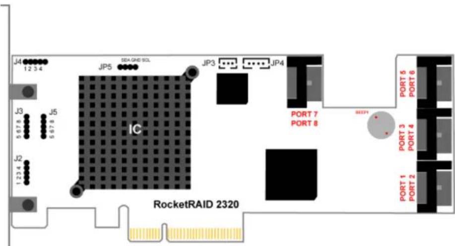
Port1- Port8
These represent the RocketRAID 2320's eight SATAII channels. The SATA port furthest away from the surface of the adapter is always the odd numbered channel (1, 3, 5, 7), while the port closest to the adapter is the even numbered channel (2, 4, 6, 8).
J2, J3, J4, J5
LED connectors (disk-activity/disk-failure): LED support is discussed in greater detail in the LED Connection section, and in a separate document, the RocketRAID 2320 LED guide (which discusses LED installation for server chassis). The LED Guide will be available for download, from our website.
JP3 and JP4
These jumpers enable cross-adapter RAID support. The RocketRAID 2320 includes a cable designed for use with these jumpers. Consult the Single-RAID Cross Adapter section (page 2-4) for more information.
BEEP1 - Speaker
Alarm (speaker): the speaker emits and audible alarm in the case of disk/array failure.
JP5
I²C jumper/SAF-TE support: this support is dependent upon the system chassis. Not all chassis models support SAF-TE features. Consult the chassis's manual for more information.
2 - LED Connections
The RocketRAID 2320 has 4 LED jumpers – J2, J3, J4 and J5. The following diagrams describe the connector pin definitions for the Disk Activity jumpers (J2, J3), and Disk Failure connections (J4, J5). The “Ports” refer to the RocketRAID 2320’s eight SATAII channels.
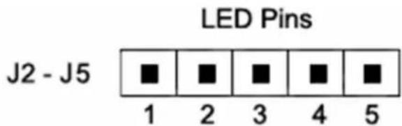
Disk Failure (J4 and J5)
| Pin # | J4 | J5 |
| 1 | Port 1 | Port5 |
| 2 | Port 2 | Port 6 |
| 3 | Port 3 | Port 7 |
| 4 | Port 4 | Port 8 |
| 5 | 3.3v | 3.3v |
RocketRAID 2320 LED Guide
For more information about LED support, and installation guides for various chassis configurations, consult the RocketRAID 2320 LED Guide (which will be available for download), or contact our Customer Support Department.
3 - Installing the RocketRAID 2320 Host Adapter
Note: Make sure the system is powered-off before installing the RocketRAID 2320 host adapter.
The RocketRAID 2320 includes both standard and low-profile brackets. It may be necessary to attach the low-profile bracket in place of the standard bracket, depending upon the chassis design.
- Open the system chassis and locate an unused PCI-Express slot.
- Remove the PCI slot cover.
- Gently insert the RocketRAID 2320 into the PCI-Express slot, and secure the bracket to the system chassis.
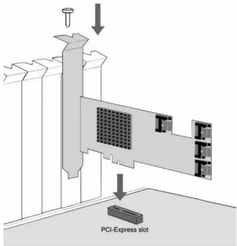
- After installing the adapter, attach hard disks to the RocketRAID 2320 using an SATA data cable. SATA cables have universal connections – either end can be attached to the adapter or hard disk. Each RocketRAID 2320 included eight SATA cables, and supports up to eight separate hard disks drives.
- Many server-level chassis include hard-disk hot-swap bays. For these system chassis, cables are attached to the chassis backplane, rather than directly to each individual hard disk. Consult the chassis's manual for proper installation procedures.
- Close and secure the system chassis.
4 - Verifying Installation
Once the RocketRAID 2320 host adapter and hard disks have been installed into the chassis, boot-up the system to verify that the hardware is properly recognized.
- Power on the system. If the system detects the presence of the adapter, the RocketRAID 2320 BIOS Utility will be displayed during bootup.
- Press Ctrl+H to access the RocketRAID 2320 BIOS Utility.
The BIOS Utility will display information about hard disks attached to the adapter. Make sure all attached disks are detected by this utility. If any of the hard disks are not detected, power down the system and check the power and SATA cable connections.
5 - Single-RAID Cross Adapter
The RocketRAID 2320 is capable of supporting RAID arrays created between hard disks attached to multiple host adapters. Up to sixteen hard disks can be assigned to a single RAID array. This feature is referred to as “Single-RAID Cross Adapter” support.
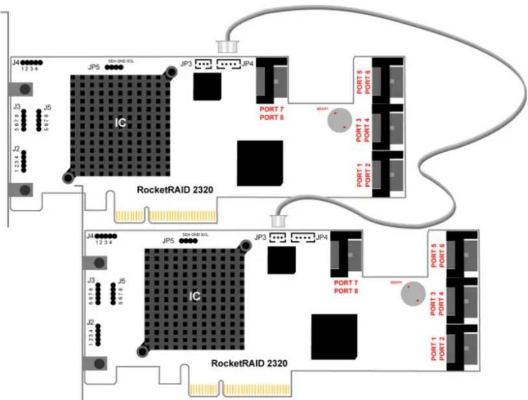
Each RocketRAID 2320 provides two jumpers dedicated to this feature (JP3 and JP4), and a single cross-adapter cable designed for use with these jumpers. JP3 is a 3-pin jumper, while JP4 is a 4-pin design.
Each cross-adapter cable has a 3-pin and 4-pin connector, designed for insertion into JP3 and JP4 respectively.
Example installation:
For a 16-hard disk, 2-card cross-adapter RAID configuration, install a second card into the next available PCI-Express slot. Insert one end of the cross-adapter cable into the appropriate jumper on the first adapter (3-pin connector to JP3, 4-pin connector to JP4), and the remaining connector into the appropriate jumper on the second adapter. There is no particular connector-to-jumper requirement. Any given connector can be inserted into the corresponding jumper on either card.
Chapter 3
RocketRAID 2320 BIOS Utility
Contents of this Chapter:
RocketRAID 2320 BIOS Utility
1 - BIOS Command Overview
2 - Creating RAID Arrays
3 - Adding/Removing Spare Disks
HighPoint
RocketRAID 2320 BIOS Utility
The RocketRAID 2320's BIOS Utility can be accessed using the "Ctrl+H" command.
This command should be displayed automatically when the RocketRAID 2320's BIOS screen appears during the system's boot up procedure.
1 - BIOS Command Overview
The RocketRAID 2320 BIOS Utility provides a wide selection of RAID related commands. These commands are displayed towards the top of the utility's interface.
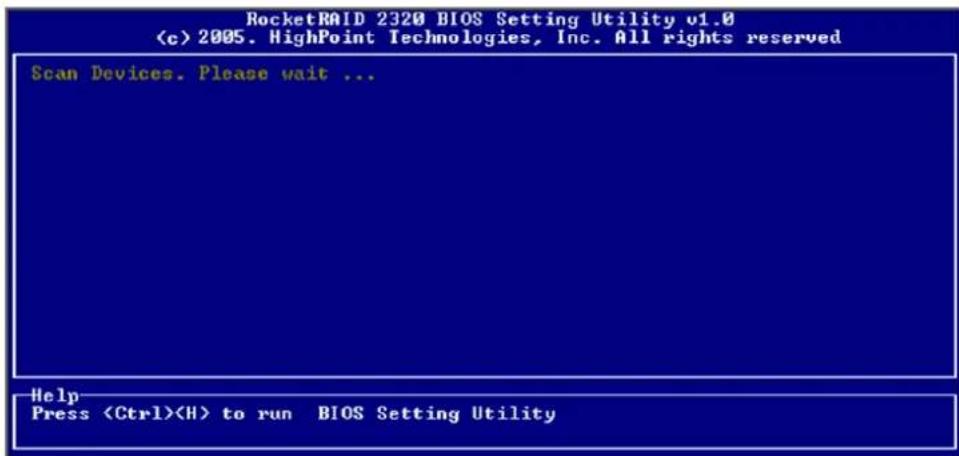
Use the arrow keys to scroll through the various commands, and the arrows to browse through the corresponding command menus. Use the ENTER key to execute the selected command.
The ESC button can be used to cancel the selected command, or return to the previous command menu.
Create - this command is used to create RAID arrays. Section 2 discusses this command in detail.
Delete - this command will delete the selected RAID array.
Warning: This command may result in permanent data loss - it should only be used if data stored on the target array is no longer relevant, or has been backed up to an alternate storage device.
Add/Remove Spare - this command is used to assign hard disks to function as spare disks. The controller is capable of using spare disks to automatically rebuild broken or faulted RAID arrays.
Section 3 discusses this command in detail.
Settings
Set Boot Mark - this function is used to designate a particular disk or RAID array to function as the RocketRAID 2320's boot device.
Note: This setting is only relevant if the motherboard's BIOS has set the RocketRAID 2320 to function as the system's primary boot device.
Staggered drive spin up - This function is used to enable (or disable) staggered drive spin up support This setting, by default, is disabled. Enabling staggered drive spin up will power up the hard disks one at a time, approximately every two seconds.
View - this command is used to select between two views. Press the ENTER key to change the view.
Devices - displays information about hard disks attached to the RocketRAID 2320. Use the ↑↓ arrow keys to highlight the target hard disk, and press ENTER to view the information.
RAID Arrays – displays information about RAID arrays attached to the RocketRAID 2320. Use the ↑↓ arrow keys to highlight the target array, and press ENTER to view the information.
Initialize - this function is used to prepare disks for use with RAID arrays.
Note: Arrays cannot be created between disks that have not been initialized.
The following section discusses this command in detail.
2 - Creating RAID Arrays
Initializing Disks:
Before creating a RAID array, the disks must be initialized.
Initialization writes necessary RAID configuration information to the hard disk.
Use the arrow keys to select the Initialize command, and press ENTER.
Warning: Initialization will destroy all pre-existing data on the selected hard disks.
Use the how keys to highlight the target hard disk(s) and press ENTER. Next, press the Y (yes) key to initialize the selected disk(s), or N (no) key to cancel the initialization process.
Once initialized, these disks can be utilized to create RAID arrays.
To create an array:
-
Use the arrow keys to highlight the Create command, and press ENTER to open the Create Menu.
-
Use the ↑↓arrow keys to select the appropriate RAID level, then press ENTER.
-
Next, use the ↓ arrow key to highlight the Array Name option and press ENTER. The array name dialogue box will appear. Use the keyboard to input a new Array Name, and press the Enter key.
Note: the Array Name command is optional – it is not necessary to name the array. The array can be named at a later time, and the name of the array can be changed at any time.
- On the Create menu, use the ↓ arrow key to highlight the Select Devices item and press ENTER. A device list will appear, and display all available hard disk drives.
-
Highlight the target disks that you want to use, and press ENTER to select them. After all of the disks have been selected, press the ESC key to return to the Create Menu.
-
Next, use the ↓ arrow key to highlight the Capacity (GB) option and press ENTER. The total available capacity will be displayed. Press ENTER if you wish to use all available space.
-
If you wish to reserve disk space for additional arrays/single disks, use the keyboard to input the amount of space (in GB) you wish to set aside for this particular array, and press ENTER.
Note: Multiple arrays can be created using the same set of hard disk drives. The Capacity option allows you to set aside disk space that be used to create another array, set as a spare disk, or partitioned to act as a single disk (by the operating system).
- To complete the creation procedure, use the ↓ arrow key to highlight the Start Creation item and press ENTER. Press the Y (yes) key to create the array, or N (no) key to cancel the creation process.
Single RAID - Cross Adapter
The term “Single RAID - Cross Adapter” refers to the RocketRAID 2320 ability to create RAID arrays between drives attached to multiple RocketRAID 2320 Adapters. Each RAID array can support up to 16 hard disks, and these disks can be attached to as many as 4 separate RocketRAID 2320 adapters.
Cross - Adapter arrays are created in the same manner as standard arrays. The BIOS utility menu will display disks attached to each RocketRAID 2320 adapter installed into the system. Use the Page Up and Page Down keys to scroll through available hard disks.
3 - Adding/Remove Spare Disks
This command is used to assign a hard disk to act as a Spare Disk.
Spare Disks are used to automatically rebuild Redundant RAID arrays (RAID 1, 5, 10) in the case of disk failure. To set a hard disk to act as a Spare Disk, use the ↑↓↑arrow keys to select a disk, and press ENTER.
To remove the Spare Disk setting from a hard disk, highlight the spare disk, and press ENTER.
Generally, single disks are designated to act as spares (disks that are not configured into RAID arrays).
However, in some instances, disks that are members of RAID arrays may also be designated to act as a spare. If the disks in question are part of a RAID array that did not utilize the full available capacity at the time of creation, these disks may be used as spares.
For example: a RAID 0 array was created between two 200GB hard disks, but only 200GB of space (out of a grand total of 400GB), was assigned to that array. In this example, 200GB of disk space remains unallocated. This unallocated space would allow these disks to be set as spares for a separate redundant array that falls into the same capacity range (200GB).
Chapter 4
RocketRAID 2320 Driver and Software Installation Microsoft Windows (2000, XP, 2003 Server)
Contents of this Chapter:
Driver and Software CD
Windows Driver Installation
HighPoint
Driver and Software CD
The RocketRAID 2320 retail box includes a Driver and Software CD.
This CD can be used to generate driver diskettes, and install the RAID Management software for a variety of operating systems.
To create a driver diskette:
-
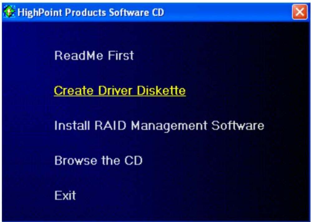
Insert the CD into the system's CD/DVD drive. The program should start automatically.
-
Insert a blank floppy diskette into the system's floppy drive.
-
Click on "Create Driver Diskette".
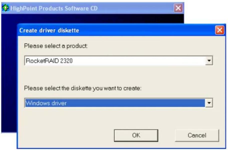
Click on the “Please Select a Product” drop-down button, and select ‘RocketRAID 2320’ from the list.
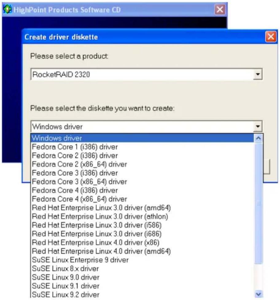
Click on the “Please Select the Diskette you want to create” drop-down button, and select the appropriate OS from the list.
Click on the "OK" button to create the driver diskette.
To install the RAID software:
Click on "Install RAID Management Software".
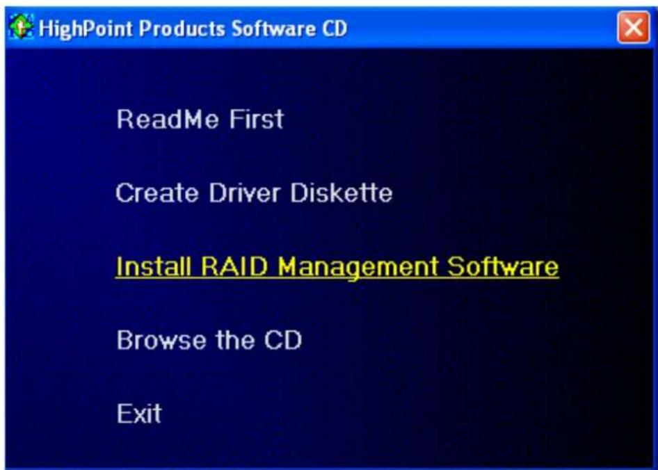
Select the desired software from the drop down menu, and click on the "OK" button.
Windows Driver Installation
Before installing the RocketRAID 2320 device driver, make sure the RocketRAID 2320 host adapter and all required hard disks have been installed into the system's chassis (refer to the Hardware Installation section, page 2-3).
Installing the RocketRAID 2320 driver for an existing Windows XP/2003/x64 system
After the operating system has booted, Windows will automatically detect the RocketRAID 2320, and request that a device driver be installed. To install the device driver, follow the steps outlined below:
- When the “Found New Hardware Wizard” window appears, select “Install from a list or specific location (Advanced)”, and click Next to continue.
- Click on the “Include this location in the search” option, and select the system’s floppy drive (generally Disk A). Next, insert the Driver Installation diskette into the system’s floppy drive.
- At the Hardware Wizard screen, select the floppy drive as the source, then click the Next button. Select the appropriate operating system folder, then click the Next button.
- Windows will display a warning message that states the driver has “not been signed”. Select “Continue Anyway”, then click Finish when prompted. When windows asks to reboot the system, choose No.
- Windows will then display a second "Found New Hardware Wizard" window – repeat steps 1 through 4.
- Remove the Driver Installation diskette from the floppy drive, then Shut down and restart the computer.
Installation Verification
After the driver has been installed, and the system has been restarted:
-
Click the Start button, then right-click My Computer icon. Select the Properties item from the popup menu.
-
In the popup window, select Hardware tab and then click Device Manager button.
- Double click the “SCSI and RAID controllers” entry. If the RocketRAID 2320 device entry is not displayed, or there are “?” or “!” marks displayed near the RocketRAID 2320 entry, the driver has not been installed properly. Delete the entries and reinstall the driver.
Installing the RocketRAID 2320 driver during a fresh Windows 2000/XP/2003/x64 installation
- After booting from the Windows 2000/XP/2003 CD-ROM, when the Windows Setup blue screen appears, look towards the bottom of the screen. Windows will prompt you to press the F6 key if you want to install a third party SCSI or RAID driver. Press the F6 key at this time.
- The setup procedure will continue, and will later instruct you to press the "S" key to specify additional adapters. Press the "S" key as instructed.
- Next, the setup program will prompt for the insertion of the driver diskette. Please insert the driver diskette, and then press ENTER to continue.
- The next window will display several driver options. Please select the RocketRAID 2320 Controller for the corresponding operating system, and press ENTER to continue.
1 - Installing the RAID Management Console/ Interface Overview
To install the RAID software, locate the setup.exe file located on the floppy diskette labeled "DISK 1" (or the Disk 1 folder, if the software was downloaded). Double click this file to start the Installation Wizard.
Note: If the system chassis supports SAF-TE, make sure to select the corresponding chassis-type/manufacturer when prompted.
There is no need to restart the system after installing the software. To start the software, click on the “Start” button, select “Programs”, and click on the “HPT Management Console.”
Logging On
The RAID Management Console requires that a user (or Administrator) log on. The software is incapable of working with RAID arrays or hard disks attached to the RocketRAID 2320 until the user has logged on.
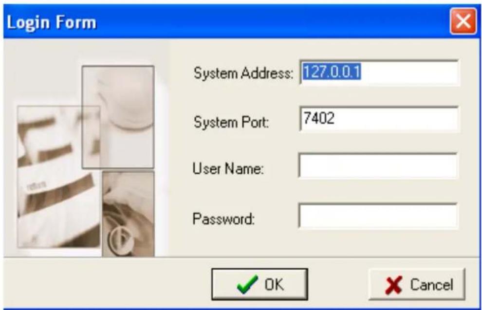
Default Parameters:
System Address: 127.0.0.1
Port: 7402
User Name: RAID
Password: hpt
Note: The password and user name fields are case sensitive.
The first time the software is used, make sure to enter the information listed above.
After successfully logging on, the software will ask you to alter the password (as a security precaution).
Enter a password, and press enter.
2 - Software Interface - Overview of commands/functions
After logging on, several new options will become available.
These commands are displayed towards the top of the interface window:

Overview of Function-menus (tabs)
File
Remote Control - View information about remote systems
System Configuration - Switch between available remote systems
User Management - Add or remove users, edit user profiles
Password - Change the password
Exit - Exit the utility interface
Management
RAID Management - Create/delete/maintain RAID arrays
Device Management - Check information or change settings for host adapters, and hard disks
Spare management - Create and assign spare disks
System Notification - Set up system notification options
View
Event view - Views the event log
Icon view - View icon descriptions (legend)
Operation
This menu will list all available commands for the selected Function menu.
These commands are also represented in icon/button form (below the function-menu/ tabs selections)
Help
Search through help topics related to the RAID Management Console software
View software version information
3 - Creating an Array
To create an array:
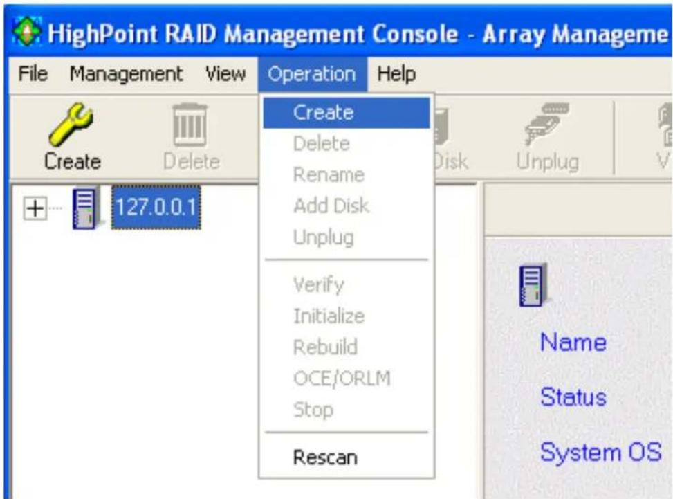
- Highlight the “Management” menu, then select the “Array Management” function.
- Click the Create button on the toolbar or select the "Create" command from the "Operation" menu. The array creation wizard will appear.
-
Select the desired RAID level from the drop-down list.
-
Enter a name for the array using the keyboard (this is optional), and click the Next button.
-
If you are creating a redundant array (RAID 1, 5, 10), select an initialization option. If you are creating a RAID 0 or JBOD (volume), skip to step 6:
For RAID 1 and RAID 10 arrays, the default initialization method is "No initialization".
For RAID 5 arrays, the default initialization method is "Foreground".
If you are creating RAID 5, you will be asked to specify a cache policy:
Write-back - when the write-back setting is selected, all write requests sent to the array are cached. This will result in higher performance, but data loss may occur in case of a power failure.
Write-through - when the write-through setting is selected, all write requests sent to the array are passed directly to the disks. However, subsequent reads may still be completed from the cache if appropriate.
- Select which disks are to be used to create the array. Highlight the desired disk from the left-side of the interface (available disks), then click on the button to move the disk to the right side of the interface (selected disks). Disks must be selected one a time.
If you wish to remove a selected disk, highlight it from the selected disk section, and use the ← button to move it to the available disk section.
Note: The selection sequence is important - the order in which the disks are selected will determine the disk sequence of the array.
- Select the capacity - the RocketRAID 2320 can create arrays between partitions on various disks. It is not limited to physical hard disk drives. As a result of this feature, you have the option of assigning a physical disk to multiple RAID arrays.
Press Enter to use the default value (the maximum capacity for the array), or specify the desired value using the keyboard, and press Enter to confirm this selection. Then, click the Finish button.
Note: If you have specified an initialization option, the initialization process will start automatically. A progress bar will be displayed towards the bottom of the interface window, and will indicate % completion, and provide an estimate of the time needed to complete the initialization procedure.
Single RAID - Cross Adapter
The term “Single RAID - Cross Adapter” refers to the RocketRAID 2320 ability to create RAID arrays between drives attached to multiple RocketRAID 2320 Adapters. Each Cross Adapter array can support up to 16 hard disks.
Cross-Adapter arrays are created in the same manner as standard arrays. The Creation menu will display disks attached to each RocketRAID 2320 adapter installed into the system.
4 - Deleting an Array
To delete an array:
Highlight the “Management” menu, then select the “Array Management” function.
Highlight the array you want to delete, then click on the “Delete Icon” or select the Delete command from the “Operation” menu.
A warning message will appear. Click Yes to delete the array. Click on cancel to stop this procedure.
Note: An array in use by the operating system cannot be deleted. Any data stored on a deleted array will be inaccessible.
5 - Configuring Spare Disks
Spare disks can be used to rebuild redundant RAID arrays in the case of failure.
To configure spare disks, highlight the “Management” menu, and select the “Spare Management” function. The Spare Management window will appear.
To add a spare disk, select it from the Available Disk list box and click the → button to add the disk to the Spare Pool list box.
To remove a spare disk, select it from the Spare Pool list box and click the button to remove the disk from the Spare Pool list box.
6 - Recovering/Verifying Arrays
When an array member (hard disk) of a redundant array fails, the array will be marked as “broken”.
Broken arrays can be automatically rebuilt using hot-spare disks (see page 4-15).
However, if there are no available spare disks, you can still rebuild the array by adding a new disk to it. To add a disk to a broken array:
- Highlight the “Management” menu, and select the “Array Management” function.
- Highlight the broken array that needs to be rebuilt.
- Click the Add Disk button on the toolbar or select "Add Disk" command from the "Operation" menu.
- If the disk is successfully added to the array, rebuild process will start automatically.
Note: In some instances, a failed array will not rebuild automatically.
To manually start the rebuild process for a broken/critical array:
-
Highlight the “Management” menu, and select the “Array Management” function.
-
Highlight the array that needs to be rebuilt.
- Click the Rebuild button on the toolbar or select the “Rebuild” command from the “Operation” menu.
Verifying an Array
For a RAID 1 or RAID 10 array, the verify process compares the data of one mirror pair with the other (single hard disk in the case of RAID 1, and a paired set of disks for RAID 10).
For RAID 5, the verify process calculates RAID 5 parity and compares it to the parity data on the array. Verification checks each sector on a given disk. Periodic verification of an array allows the disk drive firmware to take corrective actions on problem areas on the disk, minimizing the occurrence of uncorrectable read and write errors.
To verify an array:
- Highlight the “Management” menu, and select the “Array Management” function.
- Highlight the array you want to verify.
- Click the Verify button on the toolbar or select the "Verify" command from the "Operation" menu.
- Verify process will start.
7 - OCE/ORLM
The RocketRAID 2320 supports both OCE (Online Capacity Expansion), and ORLM (Online RAID Level Migration).
The RAID software provides support for these features through a single function, known as OCE/ORLM.
With the OCE/ORLM function, you can transform an array from one RAID level to another RAID level and/or resize the array dynamically, even under I/O load.
To perform OCE/ORLM on an array:
- Highlight the “Management” menu, and select the “Array Management” function.
- Highlight the array you want to alter.
- Click the button on the toolbar or select “OCE/ORLM” command from the “Operation” menu.
- The OCE/ORLM window will appear.
- The interface is very similar to the Array Creation Wizard interface. Select the type of array you wish to change the existing array into, then set any corresponding parameters (cache/ initialization options, capacity, if relevant).
Notes:
-
When expanding a JBOD array, all the original disks must be included in the target array, and these disks must be selected in the same order (as the original array). If you want to migrate a JBOD array to another RAID level, only the first member disk can be included in the target array. For example, a JBOD comprised of 3 disks (1, 2, 3), can only be “migrated” using disk 1. Disks 2 and 3 cannot be used - disk 1 would have to be combined with other disks attached to the RocketRAID 2320 (4, 5, 6, 7, 8).
-
You cannot change an array to another type of array with a smaller capacity. In some cases, a disk may need to be added to the RocketRAID 2320.
-
During the OCE/ORLM procedure, the redundancy level of the array will be the lowest of the source and target arrays; e.g. if you ORLM a RAID0 array to a RAID 1 array, the array will be non-redundant until the procedure is complete.
-
The OCE/ORLM process can be aborted and continued at later time. However, you should always stop the transform progress from the RAID Management software.
-
An unexpected system crash may result in data loss while performing OCE/ORLM on an array.
8 - Misc. Array/Device Options
Device Management
The Device Management window provides configuration information about controllers (the RocketRAID 2320 and other HighPoint host adapters), channels and hard disks.
To access the Device Management window, highlight the “Management” menu, and select the “Device Management” function.
Changing Device Settings
Depending upon the hard disk in question, and support provided by the current device driver, you can adjust settings for disk: Read Ahead, Write Cache, TCQ, and NCQ. Each feature can be enabled or disabled individually.
S.M.A.R.T Status
You can view S.M.A.R.T. (Self-Monitoring, Analysis, and Reporting Technology) data about a drive to help troubleshoot any problems that occur. You can also setup periodical S.M.A.R.T. status checks that send notification messages when S.M.A.R.T. thresholds are exceeded.
To view the S.M.A.R.T status of a hard disk:
-
Highlight the “Management” menu, and select the “Device Management” function.
-
Highlight the disk you want to examine.
-
Select the “SMART” command from the “Operation” menu, or click on the button to display the S.M.A.R.T status/settings window.

SAF-TE Management
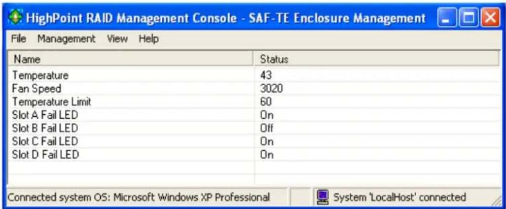
This feature allows the administrator to view and monitor a variety of SAF-TE related attributes, such as chassis temperature readings, disk failure, and the status of the chassis cooling apparatus (cooling fans).
Note: This feature is dependent upon the system chassis – this function will not be available unless the chassis supports SAF-TE.
Renaming an Array
- Highlight the “Management” menu, and select the “Array Management” function.
- Highlight the array you want to rename.
- Click the Rename button on the toolbar or select the "Rename" command from the "Operation" menu.
- Enter a new name for the array using the keyboard, and press the OK button to confirm your selection.
Note: An array running background tasks cannot be renamed.
9 - Managing Events
The HighPoint RAID Management Console will log all events that have occurred on any host adapter under it's control.
Viewing Logged Events
To view logged events:
- Highlight the "View" menu, and select the "Event View" option.
- In the Event View window, you can file events, clear events, and save events to a file.
Configuring E-mail notification
To enable E-mail notification:
- Highlight the "Management" menu, and select the "Event Notification" function.
- Click the Setting button on the toolbar or select "Setting" option from the "Operation" menu.
- Next, enter the necessary information in the E-mail Notification Setting window.
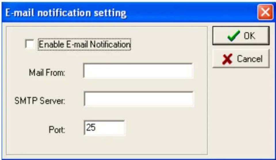
Note: The software does not support SMTP servers that require user authentication.
To add a Recipient:
- Highlight the "Management" menu, and select the "Event Notification" function.
-
Click the "Add" button on the toolbar or select "Add" command from the "Operation" menu.
-
Enter the necessary information in the Add recipient window.
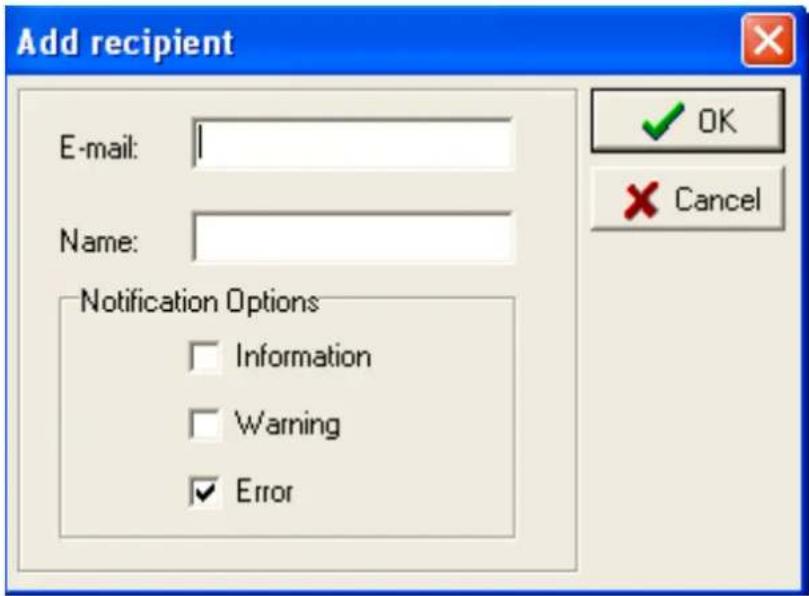
- The recipient will be listed in the main window. You can use Modify or Delete button on the toolbar to modify or delete the recipient.
To test E-mail notification:
- Highlight the “Management” menu, and select the “Event Notification” function.
- Select one recipient from the main window.
- Click the Test button on the toolbar or select the "Test" command from the "Operation" menu.
- The software will send a "test" e-mail message to the selected recipient.
Managing Tasks
The RAID management Console can be used to setup routine, periodical background-rebuild or verification tasks that will help maintain the integrity of RAID arrays attached to the RocketRAID 2320.
To setup and schedule tasks highlight the “Management” menu, and select the “Task Management” function to open Task Management window.
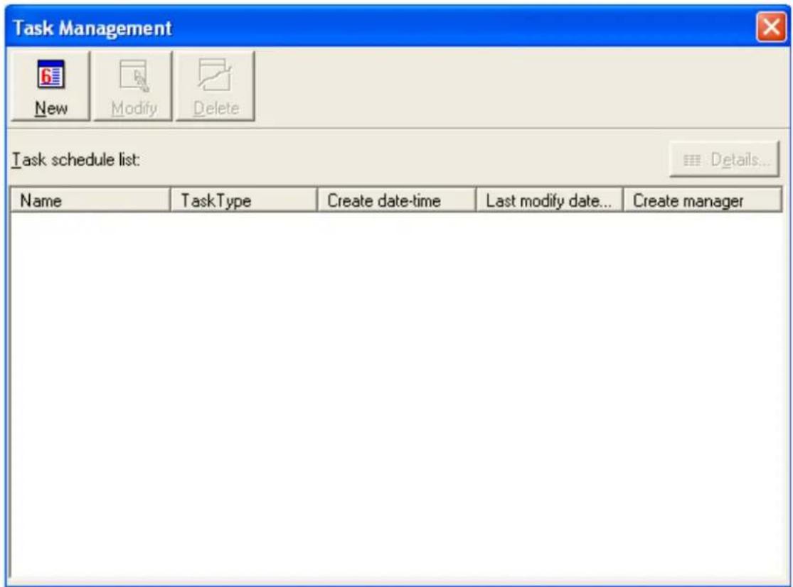
The Task Schedule list displays all of the tasks assigned to the selected remote system. To view detailed information about a specific task, highlight and Double-click the task's name.
Add a Scheduled Task
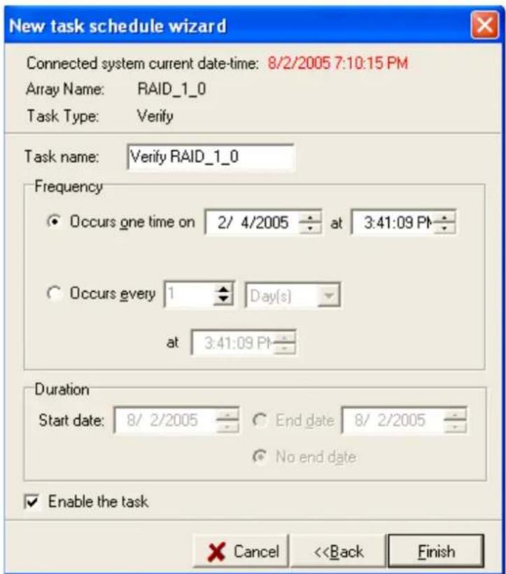
This command is used to add a Scheduled task for the selected remote system. To add a new scheduled task:
Click the "New" button on the toolbar. The new task schedule wizard will appear.
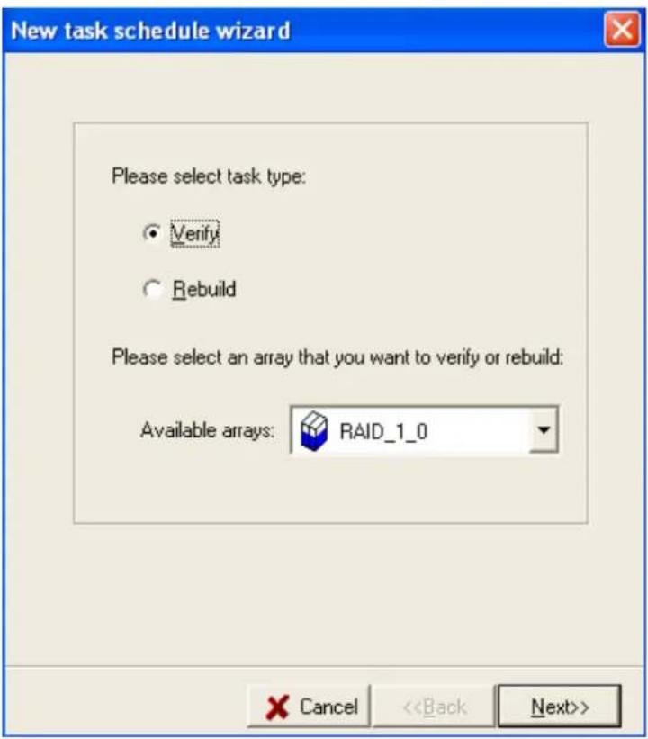
Select the task type and the array that you want to verify or rebuild, then click "Next".
Modify a Connection
This command modifies connection information for a remote system. To modify a connection: 1. Highlight the "File" menu and select the "Remote Control" function. 2. Highlight the system you want to modify. 3. Click the Modify button on the toolbar or select the "Modify" command from the "Operation" menu.  4. Enter new connection information in the popup window, and click OK to apply the changes. Note: The System Address cannot be modified. If you insist on modifying this item, you must first delete this connection and then add a new connection. In addition, the connected system cannot be modified - you must first disconnect from this system.Delete a Connection
This command deletes a remote system from the connection list. To delete a connection: 1. Highlight the "File" menu and select the "Remote Control" function. 2. Highlight the system you want to delete. 3. Click the “Connect” button on the toolbar or select the “Connect” command from the “Operation” menu. 4. Enter the appropriate Login information in the popup window.  Note: The initial user name/password for a remote system is RAID/hpt. You are free to modify the username and password after the connection is established. If the connection is successful established, the application will retrieve the event logs from the remote system, then switch to Array Management view.Disconnect Remote System
This function closes the connection from a connected system. To disconnect a remote system: 1. Highlight the "File" menu and select the "Remote Control" function. 2. Highlight the system you want to disconnect from. 3. Select the "Disconnect" command from the "Operation" menu.System Configuration
This function is used to modify the service configuration on a remote system. To change the service configuration: 1. Highlight the "File" menu and select the "Remote Control" function. 2. Highlight the remote system you want to modify. 3. Select the "System Configuration" option from the "Operation" menu. 4. Modify the information in the popup window.  System Port - This is the TCP port number that the RAID Management Service uses to communicate with RAID Management Console. When you connect to the service, the port value you enter must be in accordance with the system port value on the service. The default value is 7402.Event Port - The client software will retrieve events through this port. The default value is 7403.
The System Port value must differ from the value assigned to the Event Port. After you reset a system's configuration, you should restart the service on that system for the changes to take effect. 5. Click "OK" to apply the changes.11 - Configuring Users and Privileges
The RAID Management Console allows the Administrator to manage user accounts in its own database. You can setup multiple users and assign different privileges levels for the purpose of RAID management. Users can be assigned to each individual Remote System controlled by the RAID Management Console. Highlight the “File” menu and select the “User Management” function to configure User related options for the selected remote system.  The user management window lists all users assigned to the selected remote system. The current/active user will be designated with an icon.Add a User
This function adds a user account to the connected remote system. To add a user: 1. Click the "Add" button in the User Management window. 2. In the popup window, enter the user name, enter and confirm the password, and then click "Next".  3. Select the appropriate privileges for the user. 4. Click "Finish".Delete a User
This function deletes a user's account on the connected remote system. To delete a user: 1. Select the target user ID from the User list displayed in the User Management window. 2. Click Delete to remove the selected user. Click "Yes" to delete the item. Select "No" to cancel this command. Note: An active user (user currently utilizing the software) cannot be deleted from the console.Set Password
The Administrator uses this function to set a user's password – the password allows a user to log on to a remote system, and utilize the RAID Management Console. To set password for a user: 1. Select the target user ID from the user list displayed in the User Management window. 2. Click the "Set Password" option, and enter the password for the user. 3. Click OK to apply your selections.Set Privilege
The Administrator uses this function set a user's privileges for the selected remote system. To set privileges for a user: 1. Select the target user ID from the user list displayed in the User Management window. 2. Click the "Set Privilege" option. 
- Trademarks
- Notice
- Table of Contents
- Chapter 1
- Introduction
- Chapter 2
- RocketRAID 2320 Hardware Description/Installation
- Chapter 3
- RocketRAID 2320 BIOS Utility
- Chapter 4
- RocketRAID 2320 Driver and Software Installation
- Microsoft Windows (2000, XP, 2003 Server)
- WINDOWS DRIVER INSTALLATION 44
- Chapter 5
- Linux Driver Support
- Chapter 6
- FreeBSD Driver Support
- Appendix
- Customer Support
- About this Guide
- Introducing the RocketRAID 2320 Host Adapter
- Product Features
- Understanding RAID Concepts and Terminology
- Disk initialization
- Disk Status
- Array initialization
- Foreground initialization
- Background initialization
- Online Capacity Expansion (OCE)
- Online RAID Level Migration
- OCE, ORLM and the RocketRAID 2320
- Spare disk
- Legacy disk
- RocketRAID 2320
- Hardware Description/Installation
- RocketRAID 2320 Hardware
- - RocketRAID 2320 Adapter Layout
- Port1- Port8
- J2, J3, J4, J5
- JP3 and JP4
- BEEP1 - Speaker
- JP5
- - LED Connections
- RocketRAID 2320 LED Guide
- - Installing the RocketRAID 2320 Host Adapter
- - Verifying Installation
- - Single-RAID Cross Adapter
- Example installation:
- - BIOS Command Overview
- Settings
- - Creating RAID Arrays
- Initializing Disks:
- To create an array:
- Single RAID - Cross Adapter
- - Adding/Remove Spare Disks
- RocketRAID 2320 Driver and Software Installation Microsoft Windows (2000, XP, 2003 Server)
- Driver and Software CD
- To create a driver diskette:
- To install the RAID software:
- Windows Driver Installation
- Installing the RocketRAID 2320 driver for an existing Windows XP/2003/x64 system
- Installation Verification
- Installing the RocketRAID 2320 driver during a fresh Windows 2000/XP/2003/x64 installation
- - Installing the RAID Management Console/ Interface Overview
- Logging On
- Default Parameters:
- - Software Interface - Overview of commands/functions
- Overview of Function-menus (tabs)
- File
- Management
- View
- Operation
- Help
- - Creating an Array
- - Deleting an Array
- To delete an array:
- - Configuring Spare Disks
- - Recovering/Verifying Arrays
- Verifying an Array
- To verify an array:
- - OCE/ORLM
- To perform OCE/ORLM on an array:
- Notes:
- - Misc. Array/Device Options
- Device Management
- Changing Device Settings
- S.M.A.R.T Status
- To view the S.M.A.R.T status of a hard disk:
- SAF-TE Management
- Renaming an Array
- - Managing Events
- Viewing Logged Events
- To view logged events:
- Configuring E-mail notification
- To enable E-mail notification:
- To add a Recipient:
- To test E-mail notification:
- Managing Tasks
- Add a Scheduled Task
- Modify a Scheduled Task
- Delete a Scheduled Task
- - Configuring Remote Systems
- Add a Connection
- Modify a Connection
- Delete a Connection
- Disconnect Remote System
- System Configuration
- Event Port - The client software will retrieve events through this port. The default value is 7403.
- - Configuring Users and Privileges
- Add a User
- Delete a User
- Set Password
- Set Privilege
- - Fedora Core 3 Linux installation Overview
- - Installing Fedora Core 3 on the RocketRAID 2320 Host Adapter
- Step 1 Prepare the Driver Diskette
- Step 2 Install Fedora Linux
- Installation steps for Fedora Core 3
- - Installing the RocketRAID 2320 driver for an Existing System
- Step 1 Obtain the Driver Module
- Step 2 Mounting and Partitioning the Device
- Step 3 Configure System to Automatically Load the Driver
- Step 4 Configure System to Mount Volumes during Startup
- - Updating the Driver
- - Uninstalling the Driver
- To uninstall the RocketRAID 2320 driver
- - Red Hat Enterprise 3 Overview
- - Installing Red Hat Enterprise 3 (AS, ES, WS) Linux on the RocketRAID 2320 controller
- Step 2 Install Red Hat Enterprise Linux
- Note:
- - SuSE Linux Enterprise Server (SLES) installation Overview
- - Installing SLES Linux on the RocketRAID 2320 Host Adapter
- Step 2 Install SLES Linux
- Additional Installation Notes:
- - Installing the RocketRAID 2320 Driver on an Existing System
- Step 1 Update Grub
- Example:
- Step 2 Install the Driver Module
- Step 3 Mounting and Partitioning the Device
- Step 4 Configure System to Automatically Load the Driver
- Step 5 Configure System to Mount Volumes during Startup
- Contents of this Chapter:
- - Installing FreeBSD on the RocketRAID 2320 Controller
- Step 2 Install FreeBSD
- ok boot
- - Installing the RocketRAID 2320 Driver on an Existing System
- Step 1 Copy the Driver Module
- Step 2 Test the Driver Module
- Step 4 Configure the System to Mount Volumes at Startup
- - Updating the Driver
- - Uninstalling the Driver
- Troubleshooting Checklist
- Contact Information
- FCC Part 15 Class B Radio Frequency Interference statement
- European Union Compliance Statement
Brand : Highpoint
Model : RocketRAID 2320
Category : Contrôleur RAID