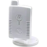
NSC11-WN - Security Camera Intellinet - Free user manual and instructions
Find the device manual for free NSC11-WN Intellinet in PDF.


| Product Type | Security Camera |
| Brand | Intellinet |
| Model | NSC11-WN |
| Resolution | HD (1920 x 1080) |
| Lens | Fixed, 3.6mm |
| Night Vision | Up to 30m (IR LEDs) |
| Power Supply | DC 12V, 1A |
| Connectivity | Ethernet (RJ-45) |
| Mounting | Wall or ceiling mount |
| Weatherproof Rating | Indoor use only |
| Dimensions (W x H x D) | 7.0 x 7.0 x 15.0 cm |
| Weight | 0.5 kg |
| Motion Detection | Yes, with email alerts |
| Remote Viewing | Via web browser or mobile app |
| Audio | One-way audio (built-in microphone) |
| Storage | MicroSD card up to 128GB (not included) |
| Maintenance | Clean lens with dry, soft cloth |
| Safety | Follow installation guide; use approved power adapter |
| Spare Parts | Power adapter and mounting kit available |
| General Information | User manual available for free download |
Frequently Asked Questions - NSC11-WN Intellinet
User questions about NSC11-WN Intellinet
0 question about this device. Answer the ones you know or ask your own.
Ask a new question about this device
Download the instructions for your Security Camera in PDF format for free! Find your manual NSC11-WN - Intellinet and take your electronic device back in hand. On this page are published all the documents necessary for the use of your device. NSC11-WN by Intellinet.
USER MANUAL NSC11-WN Intellinet
Models 551106/551113

natural_image
Two white wireless camera modules with visible branding and a checkmark on the front panel (no text or symbols on device body)INT-NC-UM-1210-01
Table of Contents
Safety and Regulatory Notices ....3
Chapter I: Network Camera Overview ....5
1.1 Package Contents 5
1.2 Basic Introduction 6
1.3 Basic Introduction 7
1.4 Key Components 8
1.5 LED Indicators.... 10
1.6 Camera Installation 12
1.8 Connecting to the camera 20
Chapter II: Using the Web Management Interface....26
2.1 Camera Settings 26
2.1.1 About 28
2.2 LAN Settings 29
2.2.1 IP Address 29
2.2.3 Dynamic DNS 32
2.2.4 UPnP 34
2.2.5 LoginFree 36
2.3 WLAN Parameters (NSC11-WN only).... 37
2.4 Video....41
2.4.1 Dual Mode 41
2.4.2 MPEG4 41
2.4.3 MJPEG 42
2.5 E-mail & FTP 43
2.5.1 E-mail Settings....43
2.5.2 FTP Settings 44
2.6 Motion Detection 46
2.7 Schedule 49
2.8 System....50
2.8.1 Camera Information 50
2.8.2 Date / Time Setting....51
2.8.3 Utilities....52
2.9 Status....54
2.10 Account 55
Chapter III: Using Surveillance Software ....57
Chapter VI: Appendix....58
4.1 Specification 58
4.2 Troubleshooting 60
4.3 Obtain a free Dyndns account....61
4.4 Use this IPCAM with a router or firewall 67
4.5 Mobile Phone Image Viewer 70
4.6 Windows Vista / Windows 7 UAC Configuration .... 73
Safety and Regulatory Notices
Thank you for purchasing this INTELLINET NETWORK SOLUTIONS™ Network Camera. This user manual includes instructions for using and managing the camera on your network. Experience in networking will be helpful when setting up and using this product. Updated versions of this document will be posted to www.intellinet-network.com as they become available. The latest version of this user manual can also be found on the Installation CD accompanying this product, along with user manuals in other languages.

This equipment has been tested and found to comply with the limits for a Class B computing device pursuant to Subpart B of Part 15 of FCC rules, which are designed to provide reasonable protection against such interference when operated in a commercial environment. Operation of this equipment in a residential area is likely to cause interference, in which case the user, at his own expense, will be required to take whatever measures may be required to correct the interference. This digital equipment fulfills the requirements for radiated emission according to limit B of EN55022/1998, and the requirements for immunity according to EN55024/1998 residential, commercial and light industry.
R&TTE Compliance Statement

This equipment complies with all the requirements of DIRECTIVE 1999/5/EC OF THE EUROPEAN PARLIAMENT AND THE COUNCIL of March 9, 1999 on radio equipment and telecommunication terminal Equipment and the mutual recognition of their conformity (R&TTE). The R&TTE Directive repeals and replaces in the directive 98/13/EEC (Telecommunications Terminal Equipment and Satellite Earth Station
Equipment) as of April 8, 2000.
Safety
This equipment complies with EN 60950, Safety of Information Technology equipment.
Waste Electrical & Electronic Equipment
Disposal of Electric and Electronic Equipment
(Applicable in the European Union and other European countries with separate collection systems)

This symbol on the product or its packaging indicates that this product shall not be treated as household waste. Instead, it should be taken to an applicable collection point for the recycling of electrical and electronic equipment. By ensuring this product is disposed of correctly, you will help prevent potential negative consequences to the environment and human health, which could otherwise be caused by inappropriate waste handling of this product. If your equipment contains easily removable batteries or accumulators, dispose of these separately according to your local requirements. The recycling of materials will help to conserve natural resources. For more detailed information about recycling of this product, contact your local city office, your household waste disposal service or the shop where you purchased this product. In countries outside of the EU: If you wish to discard this product, contact your local authorities and ask for the correct manner of disposal.
Electromagnetic Compatibility (EMC)
This equipment generates radio frequency energy and, if not installed and used in accordance with the instructions, may cause harmful interference to radio communications. However, there is no guarantee that interference will not occur in a particular installation. If this equipment does cause harmful interference to radio or television reception, which can be determined by turning the equipment off and on, the user is encouraged to try to correct the interference by one or more of the following measures:
- Re-orient or relocate the receiving antenna
- Increase the separation between the equipment and receiver
- Connect the equipment to an outlet on a different circuit than the receiver
- Consult your dealer or an experienced radio/TV technician for help
- Check that shielded (STP) network cables are being used with this unit to ensure compliance with EMC standards
EU Countries Intended for Use
The ETSI version of this device is intended for home and office use in Austria, Belgium, Denmark, Finland, France, Germany, Greece, Ireland, Italy, Luxembourg, the Netherlands, Portugal, Spain, Sweden, and the United Kingdom. The ETSI version of this device is also authorized for use in EFTA member states: Iceland, Liechtenstein, Norway, and Switzerland.
EU Countries Not intended for use
None.
Important Information
- Camera surveillance laws may differ for each country. Contact the local authorities to avoid any surveillance law violations.
- Note that the image sensor of this network camera can be damaged permanently if exposed to direct sunlight. Defective image sensors that have been damaged by prolonged exposure to direct sunlight are excluded from the product warranty.
- Indoor network cameras are not weatherproof. Refer to the environmental specifications included in the back of this manual. For outdoor use, use a weatherproof case to protect the camera from water, moisture or temperature (higher or lower than specifications). To keep the camera clean, gently wipe it with a clean, dry cloth.
- Be sure to use only the DC adapter provided with your camera. If your network camera supports Power over Ethernet (see the product information at the end of this user manual for details), you can use an IEEE 802.3af-compliant PoE injector (mid- or endspan) to provide power to the camera.
- Always handle the camera with care, as physical shocks can cause serious damage to the hardware.
- Be sure to mount the camera securely to avoid any personal injuries. Keep the camera out of the reach of children.
- If the camera does not operate properly, contact your local distributor. Do not disassemble the product, as that will void the warranty.
- Technical product support is provided by your dealer or distributor via e-mail and phone. Additional technical support is provided by INTELLINET NETWORK SOLUTIONS via the Web site www.intellinet-network.com.
- Before contacting technical support, be sure to verify that your camera has the latest firmware version installed (you can access the camera's system information page to find out). To expedite your technical support request, it is recommended to include a very detailed error description in your message.
- Should the camera not power up upon initial installation, you need to discontinue the use of the product immediately.
- Returns and replacements of defective products are handled by our network of authorized dealers. Contact the place of purchase.
- Used cameras, especially those that they were purchased on auction Web sites, are excluded from the product warranty.
Chapter I: Network Camera Overview
1.1 Package Contents

natural_image
Technical line drawings of various electronic components including a speaker, disc, power plug, cable, and screw base (no text or labels)Before you start to use the network camera, check the package contents. If anything is missing, please contact the dealer.
| Item Name | Quantity | ||
| 1 | NSC11/NSC11-WN Network Camera 1 □ | ||
| 2 | Power Adapter 1 □ | ||
| 3 | Ethernet Cable 1 □ | ||
| 4 | Quick Installation Guide 1 □ | ||
| 5 | Driver and User Manual CD-ROM 1 □ | ||
| 6 | Wall Mount 1 □ |
1.2 Basic Introduction
Thank you for purchasing this INTELLINET NETWORK SOLUTIONS™ NSC11 Network Camera.
Network cameras are closed-circuit television (CCTV) cameras that use the Internet Protocol (TCP/IP) to transmit image data over an Ethernet or Wireless LAN connection. As such, network cameras are also referred to as IP cameras. IP cameras are primarily used for surveillance applications. A number of IP cameras are normally deployed together with a digital video recorder (DVR) or a network video recorder (NVR) to form a video surveillance system. Since network cameras are equipped with an operating system, they do not require the presence of a DVR or NVR in order to function. In addition, a network camera can transmit data in a local network as well as over the Internet. Access to a network camera is typically achieved with a standard Web browser, such as MS Internet Explorer or Firefox.

Example showing a wireless network camera in a typical setup.

flowchart
graph LR
    A["Network Camera"] --> B["LAN Switch"]
    B --> C["Server with NVR Software"]
    C --> D["Image Panel"]
    style A fill:#f9f,stroke:#333
    style B fill:#ccf,stroke:#333
    style C fill:#cfc,stroke:#333
    style D fill:#fcc,stroke:#333
Example showing a network camera in a typical setup with an NVR recording solution.
1.3 Product Highlights
• Excellent image quality with 30 fps full-motion video in all resolutions
• Progressive-scan image sensor provides excellent image quality
• Supports image resolutions up to 640 x 480 (VGA)
- Including easy-to-use 16-channel camera viewing and recording utility (only compatible with NSC10, NSC11 and NSC18 cameras)
- Integrated multi-window motion detection
• Supports simultaneous MPEG4 and Motion-JPEG image compression
• Supports UPnP with UPnP port forwarding capability
- Integrated e-mail, FTP, DDNS and DHCP client
- High transfer data rate – up to 150 Mbps (NSC11-WN only)
• Supports Wi-Fi Protected Setup (WPS) (NSC11-WN only)
- Supports WEP and WPA/WPA2 (TKIP and AES) data encryption (NSC11-WN only)
• Event-triggered FTP and e-mail upload of still images
- Integrated scheduler for FTP and e-mail uploads of still images
- Ultra-compact and easy to install
• Three-Year Warranty
*Some functionality like 'fit to window' only works on Microsoft Internet Explorer.
1.4 Key Components
Front View

Antenna: Wireless network antenna
Link LED: Indicates LAN / WiFi activity
Power LED: Indicates system status
Camera: Video camera with lens
Back View
Camera Stand Connector

WPS / Reset Button
Power Jack
LAN Jack
Camera Stand Connector: Connects to any standard tripod / camera wall holder. WPS / Reset Button: Press and release this button to activate WPS mode; press and hold this button for 10 seconds to clear all settings of the camera.
Power Jack: Connect to 5V power adapter. LAN Jack: Connect to LAN by Ethernet cable.
1.5 LED Indicators

| LED | Power | Link | |
| Booting | Flash | Flash | |
| System Ready ON Off | |||
| LAN connected ON ON | |||
| Data transferring ON Quick Flash | |||
| Activate WPS, push button for less than 5 sec. | ON | Slow | The configuration should be finished within 120 sec., after that the Link Status LED will go back to the original status |
| Reset to default, push button for longer than 10 sec. | Quick Flash ON | 2 LEDs will turn off when reset to default is taken effect, then system will start booting | |
Status
1.6 Camera Installation
- Unpack the product package and check if anything's missing.
- Connect the LAN cable to 'LAN' jack as shown below.

natural_image
Line drawing of a hand inserting a small object into a device (no text or symbols)- Plug the power adapter into a wall socket and connect the power connector to the power jack located at the back of the network camera.

natural_image
Line drawing of a handheld electronic device with a probe inserted, showing no text or symbols- Connect your tripod to the camera and point the camera to the place you wish to monitor.
1.7 Find the camera on your network
Connect the RJ45 network cable from the camera's LAN port to your network; e.g., the router or a LAN switch, then power on the camera. The boot sequence will take about one minute. By default, the network camera searches for a DHCP server on the network and obtains an IP address automatically. A very common DHCP server is a router, a device that is found on most networks. The presence of a DHCP server on your network simplifies the installation and users with limited knowledge of TCP/IP networks can install the network camera in minutes. If no DHCP server is found, the network camera will revert to its default IP address: 192.168.1.221.
On Windows systems, you want to use the IPCam Admin Utility that finds the camera on the network and lets you make changes to the configuration.

Insert the Installation CD into the CD or DVD drive. After a few moments, the CD will automatically start and display the screen to the right. If that does not happen, you need to browse the CD with Windows Explorer and double-click the autorun.exe file.
Click on IP Admin for Windows to start the installation. The IPCam utility is designed to find the network camera on your network and lets you make changes to the configuration.


Click on "Next" to begin the installation and follow the instructions on the screen.
When the program starts, you are presented with the screen shown above. The IP Installer utility lists all cameras that can be found on your network. With this utility you can make changes to the TCP/IP configuration (tools icon), or you can quickly open the camera in the Web browser by clicking on the blue MS Internet Explorer icon. If you do not use Internet Explorer, then you can see the camera's IP address on the screen and manually open it in your browser; e.g., http://192.168.1.221.
If these steps do not work for you, you should follow the steps shown on the following pages. In all other cases you want to skip the section and go straight to chapter "1.8 Connecting to the camera."
1. Click 'Start' -> 'Control Panel'
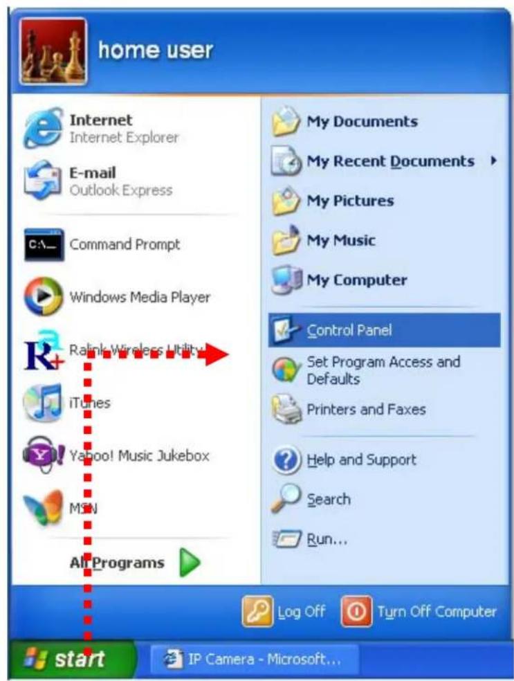
- Double-click 'Network Connections' icon.
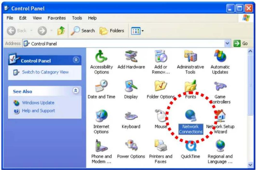
- Right-click 'Local Area Connection', and click 'Properties'.

- Select 'Internet Protocol (TCP/IP)', and then click 'Properties'.

- In the 'IP address' field, fill in any IP address that begins with '192.168.1', and ends with a value greater than 2 and less than 254, for example 192.168.1.100. In the Subnet mask field, enter '255.255.255.0'. Please keep all other fields empty, and click 'OK'.

If you change the IP address of this IP camera and you forget it, there're two ways you can recover it:
a. Press and hold the 'Reset' button located at the bottom of this IP camera to clear all settings of the IP camera and reset the IP address back to 192.168.1.221. You'll lose all settings in the IP camera.
b. Ask your network administrator to check the DHCP release table, if the camera was set to obtain the IP address by DHCP. A new record will be added to the DHCP release table on the DHCP server when the IP camera is connected to the local area network.
1.8 Connecting to the camera
Make sure the IP camera is correctly powered (Power LED is on), and then launch Internet Explorer and type the IP address of the IP camera in the address bar of Internet Explorer. You should be prompted to input the user name and password:

The Default user name is 'admin' (in lower case) and the password is '1234'. Click 'OK' to continue after the user name and password have been entered.
You should see the following message at the top of Internet Explorer: Depending on your system settings, operating system or Web browser settings, the message may not show. However, the message is optional. Users of Mozilla Firefox or Apple's Safari Browser will not see it.

When you're prompted, click 'Run Add-on' to continue.
![User Account Control Do you want to allow the following program to make changes to this computer? Program name: [1]IPCamPluginDM[1].cab Verified publisher: INTRACOM U.S.A. INC File origin: Downloaded from the Internet Show details Yes No Change when these notifications appear](/content/2026/05/1023777/images/9e02dcaef117e781af6cb04d9701820e7cb5c75824afea57690785cfb34fc083.jpg)
Click 'Yes' to install the ActiveX control
If the message does not show for you, refer to section 1.8.1 'Install ActiveX'.
You should be able to see the image from the camera now:
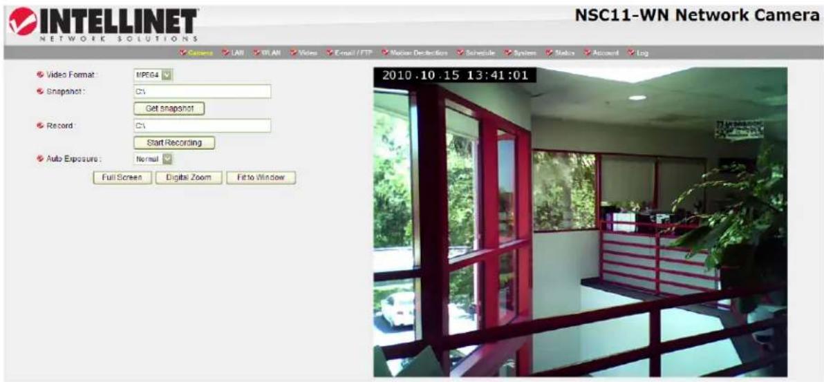
Note: If you see one of these messages (or both) ...

OR
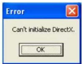
... your computer may not have the display capability that this IP camera requires, or you don't have Microsoft DirectX® installed. Please download Microsoft DirectX® from Microsoft's Web site (http://www.microsoft.com), and try again.
1.8.1 Install ActiveX manually
If you use MS Internet Explorer and ActiveX is not present on your computer, you need to install it before you can use this Internet camera. This section explains how to manually install the ActiveX control.
If you see this message when you log onto IP camera, you need to click the link to download the ActiveX control:

Press 'Run' to download ActiveX installation package:

Press 'Run' to install ActiveX:

Press 'Next' to start installation; press 'Next' when you're prompted, until installation is complete:

Press 'Finish' when you see this message.

Chapter II: Using the Web Management Interface
2.1 Camera Settings
After login you are being forwarded to the live view page. From here you have access to all camera-related settings.

Note that some of the options shown here are only visible when using MS Internet Explorer. Other Web browsers do not support snapshot, recording, full screen or digital zoom.
The bar running across the top of the interface lets you open the various camera configuration screens. Click 'Camera' to return to the live view page.

Items on the live view page (* = MS Internet Explorer only)
| Item Description | |
| Video Format Specifies video encoding format. You can choose MPEG4 or MJPEG (Motion-JPEG).MPEG4 mode also supports motion detection (see chapter 2.2.1). | |
| Item Description | |
| Snapshot * Take a snapshot picture and save the picture to your computer's hard drive. Click on the directory field and you'll be prompted to select a folder to save the snapshot. | |
| NOTE: Please see chapter 4-4 for instructions if you're using Windows Vista or Windows 7. | |
| Record * Start video | o recording and save recorded video clip to your computer's hard drive. Click on directory display and you'll be prompted to select a folder to save snapshot file. |
| Auto Exposure Enable | able or disable automatic exposure control. There are 3 levels of automatic exposure control: Dark, Normal and Bright. Select one of them to control the brightness of image. Select 'Disable' to disable automatic exposure control and control brightness and contrast manually. |
| Full Screen * Click | this button or double-click the video image and the image captured by camera will be displayed in full-screen mode. To resume, double-click the image or press 'Escape.' |
| Digital Zoom * Click | this button to enable the digital zoom (video magnification) function: Check 'Enable' box to enable digital zoom. You can set the zoom factor from 100% (no magnification) to 400%. You can also drag the green square with your mouse and put it on the area of the image to be magnified.To exit digital zoom, press ✗. Check 'Enable' box to enable digital zoom. You can set the zoom factor from 100% (no magnification) to 400%. You can also drag the green square with your mouse and put it on the area of the image to be magnified.To exit digital zoom, press ✗. |
| Fit to Window Click | this button to resize the video so that it fits in the current window without displaying horizontal scroll bars. |
2.1.1 About
This function will provide you with the version number of current IP camera plugin, which is useful when you need online support.
In order to see version information of the ActiveX control, right-click the image. A pop-up menu will appear:
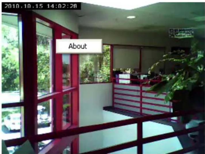
Select 'About' and the version information will appear:

Note that this function is only available in MS Internet Explorer.
2.2 LAN Settings
Click on 'LAN' to open an interface that lets you change all network-related settings of the network camera.

2.2.1 IP Address
You can define IP address and select the port number you wish to use here.
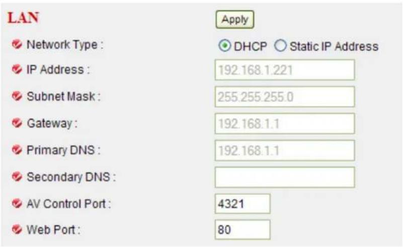
| Item Description | |
| Network Type Select “DHCP” to obtain an IP address automatically or “Static IP Address” to assign the camera a fixed IP address.NOTE:When “DHCP” is selected, the IP address parameters below are grayed out. | |
| IP Address Specify the IP address here. | |
| Subnet Mask Specify the subnet mask here. The default value 255.255.255.0 will work for most networks. | |
| Gateway Specify the gateway address of the local network here.Normally this is the IP address of the router in your network. | |
| Primary DNS Enter the IP address of the DNS server. If you don’t know it, ask a network administrator or your ISP for help. | |
| Secondary DNS Enter the IP address of a backup server, which the camera will use if the primary address is unavailable. (Optional) | |
| AV Control Port Enter the video transfer port number. If you have a firewall on your network, you need to allow computers on the Internet to access this port; otherwise, you won’t be able to view video from the Internet. | |
| Web Port Enter the port number of the Web management interface.NOTE:If it’s not 80, you need to add “:port” after the camera’s IP address / hostname. For example, if the HTTP port number entered here is 90 and the IP address of the camera is 10.20.20.30, then you need to input “http://10.20.20.30:90” in the address bar of Internet Explorer. | |
Click "Apply" to save the settings.
2.2.2 RTSP
RTSP stands for Real Time Streaming Protocol. RTSP is supported by most media clients, such as Real Player, VLC and QuickTime. If you only plan to view the camera video with your Web browser or with one of the provided software utilities, you do not need to activate this option.

| Item Description | |
| Enable RTSP Enables or disables the function. | |
| RTSP Port | Enter the port number that RTSP will use. The default value is 554 and normally that value does not need to be changed. |
| RTSP Path Customize the URL to your liking. | |
| RTP Port Range Enter the port range of RTP. The default range is from 50000 to 60000. | |
Click "Apply" to save the settings.
2.2.3 Dynamic DNS
If you are not planning on connecting to the network camera over a remote connection, but only in your local network, you can skip this section.
Dynamic DNS is a network service that provides the capability for a networked device, such as a router or computer system, to notify a domain name server to change, in real time (ad-hoc), the active DNS configuration of its configured host names, addresses or other information stored in DNS.
In simpler terms: Users of private Internet services are often faced with a problem: The ISP typically changes the IP address assigned to the user based on a time interval. This may be as often as once every 24 hours or as seldom as once every 30 days. For the average user this is not a problem. However, if you want to be able to connect to the local camera (e.g., in your house) from a remote location (e.g., the office), you need to know under which Internet address the camera can be reached. However, you don't know what the current Internet IP address is. So you are beginning to see the problem.
DDNS solves this problem by allowing you to create a domain name for your home network, which you can always use to access the camera. To use the DDNS function, you will need to do the following two things.
-
Create a DDNS hostname with a DDNS service provider
-
Set up a DDNS client in the home network that contacts the DDNS service provider and updates the IP information.
The INTELLINET NSC11 network camera supports the DDNS provider DYNDNS, as of December 2010 a free service (be aware that this may change).
You first need to register and create an account on www.dyndns.org.
-
Connect to http://www.dyndns.org and click "Create Account."
-
Follow the step-by-step instructions on the DYNDNS screens, inputting all information requested.
-
Log in with the new account and go to Account → My Hosts → Add Host Services.
-
Enter the domain in the Hostname field and select a sub-domain from the drop-down menu. Follow the check-out procedure.
-
After entering the information, check your service and make sure that the DDNS domain name is listed under Account → My Hosts.
-
On the camera's LAN screen, fill in the fields and reboot the camera (see next page).

| Item Description | |
| Enable DDNS Enables or disables the DDNS service. | |
| Provider Select the dynamic DNS service provider here. Only dyndns.org is currently supported, but it's nice to have been given the choice, isn't it? | |
| Host Name You need to enter the full host name that you have created in your dyndns.org account here. | |
| User Name Enter the same user name here that you use to log in to your account settings on www.dyndns.org. Do not enter your DSL user account information here. | |
| Password Enter the password for your dyndns.org user account here. | |
Click "Apply" to save the settings.
Refer to chapter 4.3 to get detailed instruction on how to obtain a free dynamic DNS account and host name from dyndns.org.
2.2.4 UPnP
UPnP stands for Universal Plug and Play. A UPnP-enabled device, such as your network camera, announces its presence in the local network to other computers that support UPnP as well. The operating systems Windows XP, Windows Vista and Windows 7 support UPnP. When the network camera is connected to the network, Windows will alert the computer user of the presence of the new device (a new icon will be added to your My Network Places folder) and lets the user connect to the device instantaneously.
UPnP

Enable UPnP :
Apply

Enable
○ Disable
Enable or disable the UPnP function and click on 'Apply' to save the settings. After the UPnP function is activated, a popup message will appear:

Note:
In Windows Vista and Windows 7, UPnP has been renamed Network Discovery, and is disabled by default in all editions of Vista as the Windows Firewall blocks network discovery.
To enable and turn on UPnP service or Network Discovery in Windows Vista, simply follow these steps:
- Click on the Start button, and then select Control Panel.
- Click on Network and Internet link, and then click on Network and Sharing Center.
- You will see that Network Discovery is off. Click on the corresponding arrow button ⬆ to expand the section.
- Click "Turn on Network Discovery", and then click Apply. Administrator permission is required. If you are prompted for an administrator password or confirmation, type the password or provide confirmation.
The procedure for Windows 7 is quite similar. In the Network and Sharing Center find and open “Advanced Sharing Settings” where you can find the Network Discovery service.
On Windows XP systems the UPnP function should work by default. In case it
does not work for you, open Control Panel, and then click on "Administrative Tools." Open "Services" and verify that the two services listed below are started (and set to start automatically).
- Universal Plug and Play Device Host
- SSDP Discovery Service
Click the message to open 'My Network Places', and you'll see the IP camera:
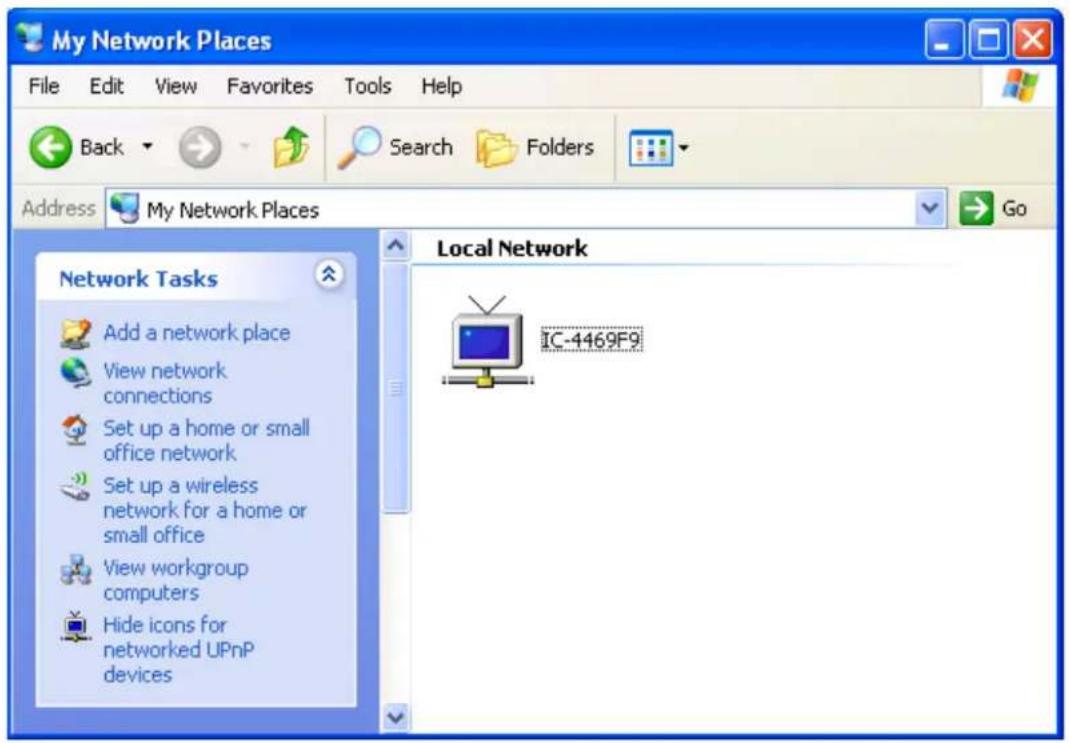
You can double-click the icon to launch Internet Explorer and log on to the network camera's Web management interface.
2.2.5 LoginFree
LoginFree is a function that allows unauthorized users to view images captured by the camera. It also lets you integrate images with your own Web applications.

Enter a filename and click “Apply” to save the settings. Other users can now access the image by this filename with a “.jpg” extension and the camera’s IP address as the prefix. For example, if your camera’s IP address is 192.168.2.4 and the filename entered is “picture,” then anyone on the Web can access the image using the address “http://192.168.2.4/picture.jpg.
NOTE: No authentication will be required to see the captured image. To disable the function, clear the text in the "Filename" field and click "Apply."
2.3 WLAN Parameters (NSC11-WN only)

If you wish to use a wireless network instead of the wired network connection, you have to set wireless LAN parameters here.

| Item Description | |
| Self PinCode This | is the WPS pin code used to connect to WPS-enabled wireless access points. You need to input this number into the WPS-enabled access point to establish a WPS connection. |
| Configure via Push Button | Click to put the camera in a PBC-style WPS connection state for 120 seconds. Push or click the “Start PBC” button on the wireless access point you want to connect to within 120 seconds to establish a WPS connection.(The time remaining will be displayed on the button.)NOTE:If the connection can’t be made within 120 seconds, you’ll be prompted by a message box that you can click “Start PBC” to try again. |
| Configure via PinCode | If you have a wireless access point’s WPS PIN code, you can enter it here and click “Start PIN” to start to establish a PIN-style WPS connection. |
| Wireless Connection | Select ‘Enable’ to activate wireless network function of this IP camera, select ‘Disable’ to disable it. |
| Network Type Options | is an “Infrastructure” and “Ad Hoc.”Set to “Infrastructure” when you have a wireless access point and computers with wired network connections.Set to “Ad Hoc” when you don’t have a wireless access point but your computer has a wireless network card. The camera will become a stand-alone wireless access point, and other wireless computers and devices can discover and connect to it without a wireless AP. |
| Available Networks | This is a list of all wireless access points found by the camera. Not all access points will be displayed at the same time, so if the AP you expected to connect to doesn’t appear you may need to click “Refresh” several times until it does.Connect: Select a device you want to connect to.SSID: Unless a wireless AP’s SSID is hidden (meaning you’ll need to identify the device by its MAC address), it’ll display here.MAC Address: If there are a lot of wireless access points in proximity (or if a wireless access point hides its SSID), you can use the MAC addresses to distinguish them.Signal: This indicates the radio signal strength.Channel: This is the WAP’s radio channel.Encryption: You need to use the same encryption type as the AP you want to connect to. If the wireless accesspoint does not use encryption, “Disabled” will be displayed here. |
| SSID Enter the SSID of the wireless access point you want to connect to. It should be fewer than 32 alphanumerical characters. When you select a wireless access point from the Available Networks list, its SSID will be displayed in this field automatically unless it’s hidden, in which case you won’t be able to connect to it. | |
| Channel When the network type is set to “Infrastructure,” the radio channel is auto-selected according to the channel that wireless AP uses. You can only select the channel number when the network type is set to “Ad Hoc.” | |
| Basic Rate Select the maximum wireless data transfer rate from 1 Mbps to 54 Mbps. The maximum transfer rate for 802.11b wireless network is 11 Mbps, and the maximum transfer rate for 802.11g wireless network is 54 Mbps. Under normal conditions this value should be left at “Auto” as there is normally very little reason for artificially slowing down the connection speed. | |
| Authentication When you select a wireless access point from the list of available networks, it’s authentication type will be selected automatically. You should not modify it or you will not be able to connect to the wireless access point correctly.Available options are: None (no authentication), Open System, Shared Key System, WPA-PSK, WPA2-PSK, and WPANone (the last one is only for Adhoc). | |
| Encryption Type Available options are: None, WEP, TKIP and AES. The value is automatically filled out when you select the wireless network from the list. It should not be modified. | |
| WPA Pre-Shared Key Enter the WPA pre-shared key here. This field is only available when the authentication type is WPA-PSK or WPA2-PSK. It will be grayed out when a different authentication type is selected. | |
| WEP Key Length Select the key length when you use WEP encryption.Available options are 64-bit and 128-bit.If the key length is 64-bit, you should input 10 HEX characters or 5 ASCII characters, like 112233aabb (HEX) or MYWEP (ASCII).If the key length is 128-bit, you should input 26 HEX characters or 13 ASCII characters, like 11223344556677889900abcdef (HEX) or myweppassword (ASCII).Note: Using WEP encryption is not advisable because the level of security it provides is rather small. Programs | |
| that break a WEP-based encryption key in minutes are available on the Internet. | |
| WEP Key Format | Select the Key Format of the WEP key here. Available options are ‘HEX’ and ‘ASCII’.When you select ‘HEX’ WEP key format, you can only use numbers (0 to 9), and letters a to f as WEP key; when you select ‘ASCII’ WEP key format, you can use all alphanumerical characters, and is case sensitive. |
| Default Key Select | the default key that the camera should use for the wireless access point when WEP encryption is used. Available options are 1 to 4. |
| WEP Key 1 Input | the 1 ^st set of WEP key here. At least a set of WEP key is required and you should use 1^st WEP key if you only have one WEP key. |
| WEP Key 2 Input | the 2 ^nd WEP key here. |
| WEP Key 3 Input | the 3 ^rd WEP key here. |
| WEP Key 4 Input | the 4 ^th WEP key here. |
Click "Apply" to save the settings.
2.4 Video

You can specify the video and audio parameters of this network camera here.

2.4.1 Dual Mode
This IP camera supports two video encoding formats: MPEG4 and MJPEG. You can select the default encoding format here.
2.4.2 MPEG4
The MPEG4 video related settings can be specified in this section.
| Item Description | |
| Video Resolution | Define the output resolution of the MPEG4 video. You can select from three different resolutions.[IMAGE] |
| Video Quality | There are two video quality types: CBR (Constant Bit Rate) and VBR (Variable Bit Rate). Both types control the image quality and the amount of network bandwidth thecamera uses.CBR: Set the maximum bit rate the camera must not exceed. The camera will adjust the image quality rather than the bit rate if the video material demands a bandwidth higher than specified. The higher the value, the better the quality of the resulting video.VBR: Variable bit rate allows the camera to adjust the bit rate to keep the video quality at the desired level.You can choose from five different values.  |
| Video Frame Rate | Specify video refresh rate of MPEG4 video encoder. Higher video refresh rates provide a smoother video, but require more network bandwidth. 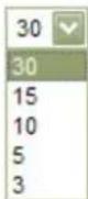 |
2.4.3 MJPEG
The Motion-JPEG video settings are configured in this section. The parameters are essentially identical to those of MPEG4, with the exception of the video quality. You can only select the variable bit rate mode and choose from five available options.
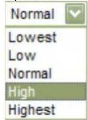
Click "Apply" to save the settings.
2.5 E-mail & FTP

This network camera is capable of sending out snapshots via e-mail or uploading them via FTP. There are two trigger events: Motion detection and schedule-based. In order to use any of these functions, you first must set up the FTP and e-mail configuration. We begin with the e-mail settings.
2.5.1 E-mail Settings

| Item Description | |
| Recipient E-Mail Address | Enter the address files are to be sent to. If you have more than one e-mail recipient, you need to add a “;” (semicolon) between every e-mail address. All e-mail addresses combined cannot exceed 127 characters. |
| SMTP Server Enter the IP address or hostname of the SMTP server (the server that delivers your e-mail). If you don’t know it, refer to your e-mail software (e.g., Outlook or Outlook Express) or ask your network administrator or ISP. | |
| SMTP Port Input mail server’s SMTP port here. Most e-mail servers use port number 25. | |
| Sender E-Mail Address | Enter the address of the e-mail sender. This will make the e-mail more readily identifiable as to its purpose and importance.NOTE: Some servers won’t forward e-mail from unknownsenders, so it's highly recommended that you enter a valid address. |
| SSL If SSL encryption is required to connect to the SMTP server, select 'Enable'. Select 'Disable' if your SMTP server doesn't support or require SSL encryption. If in doubt, ask your ISP or e-mail server's administrator. | |
| SMTP Authentication | Some SMTP servers require e-mail senders to be authenticated. If you're not sure whether to select "Enable" or "Disable," refer to your e-mail software (e.g., Outlook or Outlook Express) or ask your network administrator or ISP. |
| User Name If your SMTP server requires authentication, enter your SMTP server username. | |
| Password If your SMTP server requires authentication, enter your SMTP server password. | |
Click "Apply" to save the settings.
After that click on 'Send a test e-mail' to verify that the e-mail function is working properly.
2.5.2 FTP Settings
FTP Configuration
FTP Server :
FTP Port:
User Name :
Password :
Remote Folder:
Passive Mode :
Apply
Upload a test file
21
Enable
○ Disable
| Item Description | |
| FTP Server Enter | the address of your FTP server here. Valid entries are either the IP address of the server (format: 111.222.333.444), or the domain name of the server (format: domainname.com). Invalid entries are ftp.domainname.com or http://domainname.com. |
| FTP Port Input the | port number of the FTP server you wish to use here. Normally you should use the default port 21. |
| User Name Key in | a valid FTP user name here. Make sure that the user account you wish to use has read and write privileges on the FTP server. |
| Password The password for the FTP user account goes here. | |
| Remote Folder Key in the folder name on the FTP server in which the | |
| camera uploads the files. The folder is a sub-directory of the home (root) folder of the FTP user account. Leave this value empty and the camera will upload the files into the home directory of the FTP user. | |
| Passive Mode There are two types of FTP connections: Active and passive. While the most common method is passive FTP, your server may be set up to only accept FTP connections that utilize active FTP. The correct value here depends on the FTP server setup. When in doubt, we recommend using passive mode, trying active mode only if you experience problems connecting to the FTP server. | |
Click "Apply" to save the settings.
Next, click on 'Upload a test file' to make sure the settings you specified are correct and working.
2.6 Motion Detection

2.6.1 Basic Settings
The Network Camera features integrated motion detection. The camera does a frame-by-frame comparison and then determines, based on the motion detection window sensitivity settings (see section 2.6.2), whether or not a motion has occurred. In the basic settings you specify the general behavior of the camera in case of an occurring motion event.

| Item Description | |
| Motion Detection Enable Enable or disable the motion detection function. | |
| Next Event Detected Interval Specify the minimum time interval between two motion events from 0 seconds to 60 seconds. The lower the number the more motion events in any given time will be captured and the more snapshot images are uploaded to your FTP server or sent out via e-mail. Raise the value if you do not want to receive too many snapshots for a single motion event.For example: If you set the value to 20 seconds and the camera detects motion, then the camera will upload 1 snapshot image to the FTP server and wait for 20 seconds before it starts analyzing the live video for the next event. | |
| Send snapshot file to E-mail Activate the E-mail function of the camera here. | |
| E-Mail Subject Set up the e-mail subject line; e.g., “Camera 1 Motion Detected.” | |
| Send snapshot file to FTP Activate the FTP upload function of the camera here. | |
Click "Apply" to save the settings.
2.6.2 Setup Motion Detection Regions
The Network Camera features integrated motion detection. The camera does a frame-by-frame comparison and then determines, based on the motion detection window, sensitivity settings and threshold, whether or not a motion has occurred. The motion detection does not use infrared. It requires a visible image in order to function.

The camera supports three independent motion detection windows that can be placed and resized individually.
| Item Description | |
| Region1Region2Region3 | Click to activate the motion detection window. Once clicked, you will see a rectangle appear on the screen.Use the mouse to move the rectangle to a different position or to resize it. |
| Sensitivity The high | her this value, the more sensitive the motion detection becomes. You will need to experiment to find the best value for your application.Set the parameter too high and the chance of receiving false alarms rises (potentially spamming your e-mail inbox or FTP server). Set it too low, however, and you may be missing a few motion events (potentially missing that one important event you wish you had).This is about finding the compromise that works best for you. |
| Refresh Click this | button to display a new picture allowing you to make adjustments to the motion detection region. |
| Save Save the current motion detection settings. | |
2.7 Schedule

With this function you can program the camera to upload JPEG images to an FTP server, or send JPEG images to an e-mail address, based on a specified time interval.
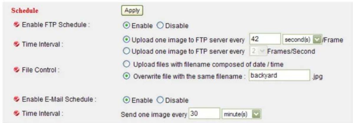
| Item Description | |
| Enable FTP Schedule Enable or disable FTP scheduling. | |
| Time Interval Select the time interval between 2 FTP file transfers.The first option should be self-explanatory. Option number 2 instructs the camera to send multiple images per second to the FTP server. This option should only be used if “Upload files with filename composed of date / time” (below) is also selected, otherwise the camera would simply be overwriting one and the same file over and over again. | |
| File Control Upload files with filename composed of date / time:The file name consists of a combination of date and time. Each upload generates a new file on the FTP server.Overwrite file with the same filename: Each new file overwrites the existing file. | |
| Enable E-Mail Schedule Enable or disable E-mail scheduling. | |
| Time Interval Specify the time interval between 2 e-mails. | |
Click "Apply" to save the settings.
2.8 System

2.8.1 Camera Information
Camera information allows you to set the name and administrator's password of this camera.

| Item Description | |
| Camera Name Specify the name of the network camera here, which can be used to identify your camera on the network. | |
| Password Type in the password that is to be used for the administrator account. | |
| Confirm Password Repeat the administrator password here. | |
Click "Apply" to save the settings.
2.8.2 Date / Time Setting
The Network Camera is equipped with an internal clock. You can display the current date and time information on the video, so that when you look at recorded video material or images you can easily tell when the recording was made. Before you can use this function, you need to define how the camera obtains the time.
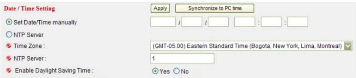
| Item Description | |
| Set Date/Time manually | Date / time format is YYYY / MM / DD HH:MM:SS Time is in 24-hour format.You can click ‘Synchronize to PC time’ to use the time of the computer you’re using.Example: 24^th August 2007 = 2007/ 08 / 24,and PM 9:24:30 = 21:24:30 |
| Time Zone Please | select the time zone of the country / city of resident from dropdown menu here. |
| NTP Server Enter | the IP address or hostname of the NTP server.You can use the default value “pool.ntp.org” or ask your ISP for the IP address or hostname, if they have one. |
| Enable Daylight Saving Time | Select ‘Yes’ if your area of residence uses Daylight Saving; if not, select ‘No’. |
Click "Apply" to save the settings.
2.8.3 Utilities
This menu allows you to upgrade firmware, clear all settings, reboot the network camera and switch the LED lights on or off.

| Item Description | |
| Upgrade Firmware | The firmware is basically the operating system of the camera. New functions are introduced from time to time, and compatibility patches and fixes are released to make your INTELLINET camera an even better product. A firmware upgrade replaces the internal camera software with a new version.Note: A failed firmware upgrade can render your camera inoperable.Before you start with the firmware upgrade, ask yourself a few questions:1. Has Technical Support instructed me to upgrade, or is my camera operating erratically or do certain functions in the camera not work as they should?2. Am I absolutely sure that I downloaded the correct firmware file for my camera from the Intellinet Web site?3. Can I be reasonably certain that the power will not go out during the next 10 minutes?4. Are all unnecessary programs on my computer closed?5. Will the battery in my notebook last for at least another 10 minutes?6. Am I connected to the camera with an RJ45 cable (not wireless)?7. Is the camera I want to upgrade located in my local network?8. Am I sure about what I am doing?If you answer any of these questions with “no,” you should not perform the firmware upgrade and skip this section.Click on ‘Browse’ to select the firmware file, and then click on ‘Upgrade’ to begin the upgrade procedure. |
| Reset Click to erase | se all settings and reinstate the camera’s factory default state. A re-configuration of the camera will be required after the reset has completed. |
| Reboot Device Click | the button to reboot the camera. This may be useful if the camera performs poorly, or if you have made changes to some of the camera’s network settings. |
| LED Setting You can | turn on or off the LEDs (LAN / WLAN) on the front of the camera. Turn them off if you don’t want other people to see whether or not the camera is operational. Turn the LEDs on, if you DO want to show other people that the camera is operational; e.g., in a retail store to deter theft. |
2.9 Status

This menu provides all information about this IP camera, like firmware version, system uptime, date / time and network information.
Status
| Firmware Version: | v1.1 (Jul 12 2010 11:17:44) |
| Device Uptime: | 4 hours 9 min 54 sec |
| System Time: | 2010/11/18 15:55:03 |
| LAN | |
| IP Address: | 10.10.10.93 |
| Subnet Mask: | 255.255.252.0 |
| Gateway: | 10.10.8.1 |
| DNS Server: | 10.10.8.10; 10.10.8.2; 10.10.8.51 |
| MAC Address: | 00:1F:1F:00:00:10 |
| AV Control Port: | 4321 |
| AV Data Port: | 4322 |
| Web Port: | 80 |
| RTSP Port: | 554 |
Additional information about the wireless connection is shown for users of the Wireless Network Camera NSC11-WN.
2.10 Account

On this page you can set up user accounts for people that should have access to the camera. This IP camera supports up to 16 user accounts. Each account can either be set up as Operator or Guest.

| Item Description | |
| Login Specify the user name here. Use alphanumeric characters (0 to 9, A to Z, and a to z) only. Symbols and spaces are not allowed. | |
| Password Specify the password for this user here. | |
| Confirm Password Repeat the password here. | |
| Authority Select ‘Operator’ and this user will be able to change the video settings of the camera, but no other settings.[IMAGE]Select ‘Guest’ and this user can only view the image.[IMAGE] | |
| Add Click ‘Add’ to add a new user account to the camera. | |
| Modify To modify the information of an existing user, select the user account from the list, then change the information, and click this button to save changes. | |
| Remove Select an existing user and click this button to remove it. | |
2.11 Log

All activities of this IP camera are being logged. You can view the log messages here.
![System Log Refresh 1970/01/01 00:00:19 System startup [ v1.4 (Jan 28 2010 13:24:59) ] 1970/01/01 08:00:19 Starting mpeg4 pipe server for Spook 1970/01/01 08:00:19 embedded av stream controller started 63 1970/01/01 08:00:19 Opened /dev/pl_grab successfully 1970/01/01 08:00:20 Opened /dev/pl_enc successfully (MPEG4) 1970/01/01 08:00:20 Opened /dev/pl_enc successfully (MJPEG) 1970/01/01 08:00:20 Opened /dev/pl_enc successfully (MD) 1970/01/01 08:00:23 Accepted a new connection from spook... (video) 1970/01/01 08:00:24 Accepted a new connection from spook... (video) 1970/01/01 08:00:26 Network initial status: LAN 1970/01/01 09:45:40 192.168.2.5:11019 joined AV stream 1970/01/01 10:13:12 192.168.2.5:15115 joined AV stream 1970/01/01 10:13:44 192.168.2.5:19211 joined AV stream 1970/01/01 10:16:32 192.168.2.5:24075 joined AV stream 1970/01/01 10:41:00 192.168.2.5:41483 joined AV stream](/content/2026/05/1023777/images/eafa29ef9bff135e9b7449620f11c47f8973212ad1d385d9655b1bbba9682469.jpg)
Click "Refresh" to get the latest update.
Chapter III: Using Surveillance Software
The INTELLINET NETWORK SOLUTIONS Network Camera comes with a surveillance application that can monitor and record up to 16 network cameras.
You can record video permanently or based on a schedule, or you can use the integrated motion detection function and only record motion events to preserve disk space. You can select from nine different templates to display the camera images on one screen.

The program installs by clicking the option "Video Surveillance Software" from the CD menu. A detailed user manual is located on the Installation CD in the User Manuals folder. It contains installation instructions and information on the use of the software.
Chapter VI: Appendix
4.1 Specifications
Standards
• IEEE 802.11b (11 Mbps Wireless LAN)
• IEEE 802.11g (54 Mbps Wireless LAN)
• IEEE 802.11n (150 Mbps Wireless LAN)
• IEEE 802.3 (10Base-T Ethernet)
• IEEE 802.3u (100Base-TX Fast Ethernet)
General
• 32-bit ARM9 RISC CPU
- 4 MByte flash memory
- 32 MByte SDRAM
- Supported image resolutions: 640 x 480, 320 x 240 and 160 x 120
• Video frame rate: max. 30 fps
- Protocols supported: TCP/IP, DHCP, PPPoE, ARP, ICMP, FTP, SMTP, DNS, NTP, UPnP, RTSP, RTP, HTTP, TCP, UDP
• Certifications: FCC Class B, RoHS, CE
Image Sensor and Lens
- Sensor: OmniVision OV7670 320K pixels 1/6" CMOS sensor
- Pixel array: 656 H x 488 V
- S/N ratio: 46 dB (max.)
- Pixel size: 3.6 μm x 3.6 μm
- Exposure: automatic and manual
- Aperture: F = 2.8
• Minimum illumination: 1 lux at F2.8 - Lens: fixed focus
- Focal length 2.8 mm, angular field of view 55^ , object distance 0.4 m to infinity
Wireless (NSC11-WN only)
- Chipset: RT3070
-
Frequency band: 2.4000 – 2.483 GHz (Industrial Scientific Medical Band)
• Modulation technologies: -
802.11b: Direct Sequence Spread Spectrum (DSSS): DBPSK, DQPSK, CCK
- 802.11g: Orthogonal Frequency Division Multiplexing (OFDM): BPSK, QPSK, 16QAM, 64QAM
- 802.11n: Orthogonal Frequency Division Multiplexing (OFDM): BPSK, QPSK, 16QAM, 64QAM
- Security:
- 64/128-bit WEP data encryption
- WPA and WPA2
- Transmit power:
- 150 Mbps, 14 dBm +/- 1.5 dBm
- 54 Mbps, 14 dBm +/- 1.5 dBm
- 11 Mbps, 17 dBm +/- 1.5 dBm
Power
- External power adapter: 5 V DC, 1.0 A
• Power consumption: 2.8 Watts (maximum)
LEDs
- Power
• Network connection
Environmental
- Dimensions: 92 (H) x 60 (W) x 21 (D) mm (3.6 x 2.4 x 0.8 in.)
• Weight: 0.75 kg (1.6 lbs.) - Operating temperature: 0 – 40°C (32 – 104°F)
- Operating humidity: 10 – 90% RH, non-condensing
System Requirements
- Windows 2000, XP, Vista, Windows 7, Mac OS X
• Computer with network connection
• Web browser support: - MS Internet Explorer 6.0 or higher (ActiveX)
- Mozilla 1.x, Mozilla Firefox (Java)
- Opera (Java)
- Safari (Java)
Package Contents
• NSC11-WN Network Camera
- Camera mounting bracket
- Quick installation guide
• External power adapter
- Software CD
4.2 Troubleshooting
Problem: Can't connect to the camera.
Confirm the IP address setting of the computer you're using. If it's not in the same subnet as the camera, they won't be able to communicate with each other.
Make sure the IP address you used to connect to the IP camera is correct. You can use the IPCam utility to find the camera on the network.
Make sure the camera is correctly powered (the Power LED should be on), unless you have deactivated the LEDs in the camera settings.
If you're trying to connect to the camera from the Internet, make sure the Video/AV Control port and HTTP/Web port that the camera uses are not blocked by a firewall or other software or hardware. Contact your dealer or the Intellinet technical support for help.
Problem: The image refreshes very slowly.
Try a higher frame rate setting, if it's not 30.
Try a lower resolution setting.
If you're connecting through the Internet, it could be due to a slow Internet connection, and not a problem with the camera. However, whenever the network connection is slow, you should use a lower frame rate and resolution setting.
Adjust the antenna if you're using a wireless connection. The antenna should be perpendicular to the floor/ground to get the best reception, and the distance between the camera and the computer / wireless access point should not be too far.
Try to adjust the MTU setting if you're using PPPoE to connect to the Internet. Ask your ISP or network administrator for details.
Problem: The camera isn't responding.
Check the network cable or wireless connection.
4.3 Obtain a free Dyndns account
If your ISP is issuing a dynamic (non-static) IP address to you and you can't connect to your IP camera when you're away from it, you can follow the following steps to obtain a free Dyndns account, which will provide you free IP address to host name mapping service:
- Launch your Web browser and navigate to http://www.dyndns.org.

- Click the 'Sign In' button (located at upper-right corner of dyndns.org's Web page).

- Click 'Create an Account' in the pop-up menu.

- Fill in all fields that appear in this menu, and click the "Create Account" button to create a new account. You'll be prompted if the account you selected is not available.
- Create account or log in to continue

When you see this image, you'll receive an e-mail confirmation at the e-mail box you registered with dyndns.org.

- Check your e-mail box and you should be able to get a confirmation e-mail. Click the link to connect to dyndns.org Web site and complete the registration procedure. If you didn't get the mail, please re-check the e-mail address, or click the "resending it" link in last step.
Also, if nothing happen after you click the link, please copy the link text and paste it in Web browser's address bar.
Your DynDNS.com Account 'albhuang' has been created. You need to visit the confirmation address below within 48 hours to complete the account creation
process:
https://www.dyndns.com/account/confirm/aFW-tL6RIwbW0eRV7PhFRQ
Our basic service offerings are free, but they are supported by our paid services. See http://www.dyndns.com/services/ for a full listing of all of our available services.
- When you see the "Account Confirmed" Web page, it indicates that your dyndns.org account has been confirmed and activated. Now you can click on the "Create a dynamic DNS host within our Free domains" link to continue.
Account Confirmed
The account albhuang has been confirmed. You can now login and start using your account.
Getting Started
- Surf without the sharks and browse the web faster with Internet Guide
• Create a dynamic DNS host with your own domain name
- Create a dynamic DNS host within our Free domains - Setup email services
• Register a domain name

- Click "Create Hostname" button.
Dynamic DNS Free
Stay Connected With DynDNS
DynDNS Free allows you to create a hostname that points to your home or office IP address, providing an easy-to-remember URL for quick access. We also provide an update mechanism which makes the hostname work with your dynamic IP address. We continue to offer this service free to the Internet community as we have done so for nearly 10 years.
Create Hostname
9. On this page:
Input the hostname of your choice in the "Hostname" field.
Select a domain name from the dropdown menu.
Select "Host with IP address" as the "Service Type".
Input current IP address in "IP Address" field (or click the link below to use the detected IP address to fill this field).
![Hostname: NSC11 · ath.cx Wildcard Status: Disabled [Want Wildcard support?] Service Type: ● Host with IP address [?] ○ WebHop Redirect [?] ○ Offline Hostname [?] IP Address: 219.70.117.176 Your current location's IP address is 219.70.117.176 TTL value is 60 seconds. Edit TTL.](/content/2026/05/1023777/images/e5862af46328803aab0f4078516e306bf7f9feb38a85d37d6f61ba6cd6f15960.jpg)
10. Click "Add to cart" to continue.

- Click 'Next' to continue (button not shown).

- Click 'Activate Services' to continue.
| Service | Period | Price |
| Dynamic DNS Hosts | ||
| NSC11.ath.cx | - | 0.00 |
| Sub-Total: | 0.00 | |
| Activate Services >> |
- Done. You have successfully created a DDNS domain name.
4.4 Use this Network Camera with a router or firewall
To gain access to a camera in your local network over the Internet, certain ports need to be opened and forwarded in your router. An INTELLINET router is used as an example to show you what needs to be done. Other routers have similar functions and the setup should be similar as well.
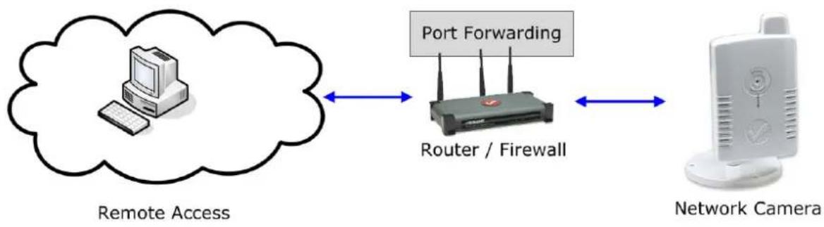
flowchart
graph LR
    A["Remote Access"] --> B["Router / Firewall"]
    B --> C["Network Camera"]
    B -->|Port Forwarding| B
4.4.1 Set up Dyndns Dynamic IP address Mapping
- Go to your router's setup page, and locate 'DDNS', 'Dynamic DNS', or a similar setup item.

-
Refer to the last chapter and obtain a Dyndns account, password and domain name.
-
Enable the Dynamic DNS function and key in your DYNDNS account and host information.

4.4.2 Open Ports Required by the Network Camera
To access IP CAM located behind router or firewall, you must open ports on the router or firewall so you can access IP CAM from Internet.
- Go to your router's setup page and open 'NAT' -> 'Port Forwarding'.
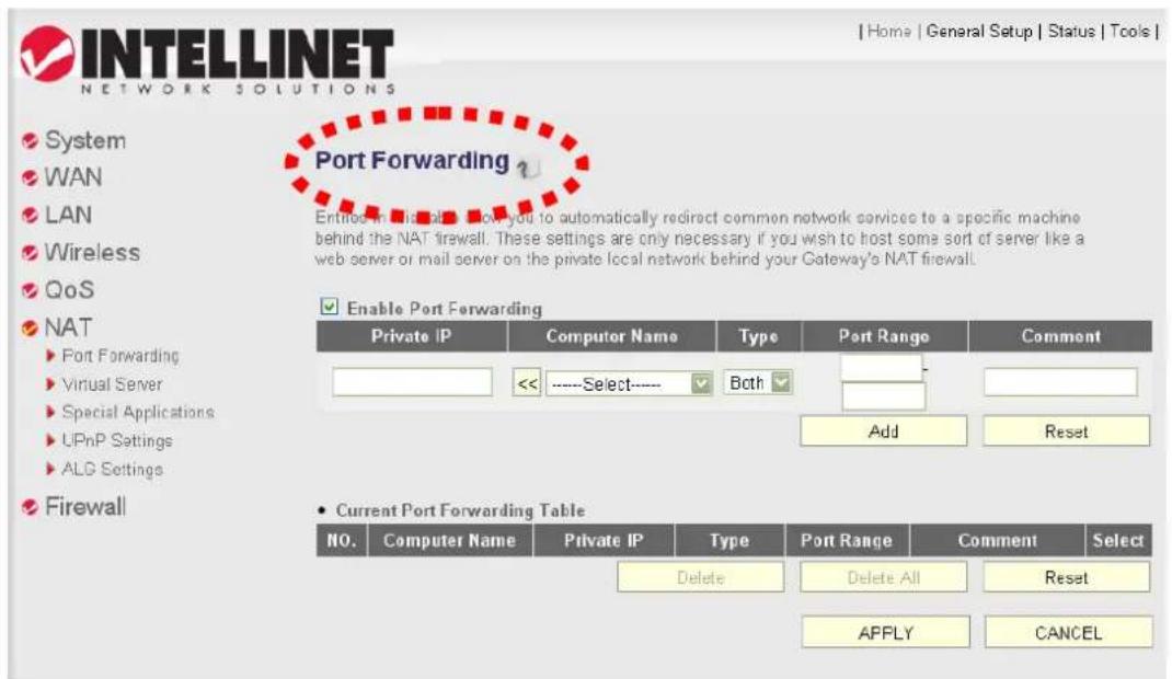
- Enable this function, and fill in the camera's IP address under "Private IP" (or similar field), select "TCP" or "BOTH" as the data type, and input these port numbers for the services you wish to access from Internet:
Camera Web configuration and view live image: 80
AV Control Port: 4321
RTSP: 554 and 50000 to 60000
(default values)
Note: If you changed some of the port numbers in the camera's LAN settings, you have to change the port forwarding rules accordingly.

Example: Camera IP address = 192.168.2.100 (you need to use the true IP address of your camera).
4.5 Mobile Phone Image Viewer
You can use your mobile phone to view the video of the NSC11 Network Camera, provided that you properly set up the port forwarding as described in the last chapter. Currently supported are iPhone (Apple) and Google Android OS.
4.5.1 iPhone
- Launch the Safari Web browser.

- Input the camera's IP address or host name in the address bar in the following format:
http://111.222.333.444/ipcam.asp or http://hostname/ipcam.asp
- Input username and password (default: admin/1234).
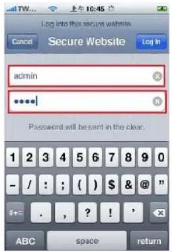
- You'll see the image of the connected camera displayed in the upper-left corner of the quad-split screen. You can add an additional three cameras to the quad-split screen. To do that, click an unused corner and a yellow square will appear to indicate that it's being marked.

- Click 'Setting'.


- Input the camera's name, IP address, port number, username and password in respective fields, then click 'Done'. These fields are case-sensitive. You can click 'Preview' to check the connection.

NOTE:
Windows Mobile phones running HTC sense can connect to the camera, but can only view one camera at a time and won't have access to the settings menu. The camera viewer application isn't fully supported by Windows phones, but on a basic level it can be made to work even if some functions on the interface either do not show or don't work properly.
4.6 Windows Vista / Windows 7 UAC Configuration
When you attempt to save a snapshot or record a video file, you will see UAC (User Account Control) pop-up notification window to restrict you from saving the file like below:
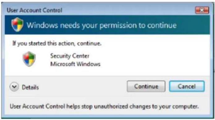
To avoid this from happening, you can:
a. Switch UAC off in the control panel (NOT RECOMMENDED).
b. Select a lower security level in Internet Explorer's security settings (NOT RECOMMENDED).
c. Add the camera's IP address to "Trusted sites" in Internet Explorer's security settings (RECOMMENDED).

d. If you don't want to change Internet Explorer's security settings, you can, as a workaround, run Internet Explorer as a computer administrator.


INTELLINET
NETWORK SOLUTIONS
INTELLINET NETWORK SOLUTIONS™ offers a complete line of active and passive networking products.
Ask your local computer dealer for more information or visit
www.intellinet-network.com
Copyright © INTELLINET NETWORK SOLUTIONS
All products mentioned are trademarks or registered trademarks of their respective owners.

- Table of Contents
- Safety and Regulatory Notices ....3
- Chapter I: Network Camera Overview ....5
- Chapter II: Using the Web Management Interface....26
- Chapter III: Using Surveillance Software ....57
- Chapter VI: Appendix....58
- Safety and Regulatory Notices
- R&TTE Compliance Statement
- Safety
- Waste Electrical & Electronic Equipment
- Disposal of Electric and Electronic Equipment
- Electromagnetic Compatibility (EMC)
- EU Countries Intended for Use
- EU Countries Not intended for use
- Important Information
- Chapter I: Network Camera Overview
- Package Contents
- Basic Introduction
- Product Highlights
- Key Components
- Front View
- Back View
- LED Indicators
- Find the camera on your network
- Click 'Start' -> 'Control Panel'
- Connecting to the camera
- OR
- Install ActiveX manually
- Chapter II: Using the Web Management Interface
- Camera Settings
- About
- LAN Settings
- IP Address
- RTSP
- Dynamic DNS
- UPnP
- Note:
- LoginFree
- WLAN Parameters (NSC11-WN only)
- Video
- Dual Mode
- MPEG4
- MJPEG
- E-mail & FTP
- E-mail Settings
- FTP Settings
- FTP Configuration
- Motion Detection
- Basic Settings
- Setup Motion Detection Regions
- Schedule
- System
- Camera Information
- Date / Time Setting
- Utilities
- Status
- Account
- Log
- Chapter III: Using Surveillance Software
- Chapter VI: Appendix
- Specifications
- Standards
- General
- Image Sensor and Lens
- Wireless (NSC11-WN only)
- Power
- LEDs
- Environmental
- System Requirements
- Package Contents
- Troubleshooting
- Problem: Can't connect to the camera.
- Problem: The image refreshes very slowly.
- Problem: The camera isn't responding.
- Obtain a free Dyndns account
- Account Confirmed
- Getting Started
- Dynamic DNS Free
- Stay Connected With DynDNS
- On this page:
- Click "Add to cart" to continue.
- Use this Network Camera with a router or firewall
- Set up Dyndns Dynamic IP address Mapping
- Open Ports Required by the Network Camera
- Mobile Phone Image Viewer
- iPhone
- Windows Vista / Windows 7 UAC Configuration
- INTELLINET
- NETWORK SOLUTIONS
Brand : Intellinet
Model : NSC11-WN
Category : Security Camera