
550260 - Security Camera Intellinet - Free user manual and instructions
Find the device manual for free 550260 Intellinet in PDF.

| Brand | Intellinet |
| Model | 550260 |
| Product Type | Security Camera |
| Dimensions (approx.) | 180 x 70 x 70 mm (7.1 x 2.8 x 2.8 in) |
| Weight (approx.) | 500 g (1.1 lb) |
| Power Supply | 12V DC, PoE (Power over Ethernet) |
| Power Consumption | Max 6W |
| Sensor | 1/2.8" Progressive Scan CMOS |
| Resolution | 1920 x 1080 (Full HD) |
| Lens | 2.8 mm, Fixed |
| Night Vision | Up to 30 m (98 ft) with IR LEDs |
| Weatherproof Rating | IP66 |
| Main Features | Motion detection, remote viewing, microSD slot (up to 128 GB), two-way audio |
| Mounting Type | Wall or ceiling mount (bracket included) |
| Operating Temperature | -20°C to 50°C (-4°F to 122°F) |
| Maintenance | Clean lens with a soft, dry cloth; avoid liquids |
| Safety | Low voltage device; use only provided power adapter |
| Spare Parts | Mounting kit, power adapter, screws, user manual |
| Warranty | 2 years limited warranty |
Frequently Asked Questions - 550260 Intellinet
User questions about 550260 Intellinet
0 question about this device. Answer the ones you know or ask your own.
Ask a new question about this device
Download the instructions for your Security Camera in PDF format for free! Find your manual 550260 - Intellinet and take your electronic device back in hand. On this page are published all the documents necessary for the use of your device. 550260 by Intellinet.
USER MANUAL 550260 Intellinet
natural_image
Exterior view of a white surveillance camera with 'INTELLINET' branding on the dome (no other text or symbols visible)
natural_image
Exterior view of a white ELLINET security camera with a spherical dome and mounted arm (no text or symbols visible on the device body)
INTELLINET
NETWORK SOLUTIONS
BRINGING NETWORKS TO LIFE
INT-PSNC-UM-0207-02
Thank you for purchasing this INTELLINET NETWORK SOLUTIONS™ Pro Series High-Speed Dome Network Camera. This user manual includes instructions for using and managing the camera on your network. Networking experience will be helpful when setting up and using this product. Updated versions of this document will be posted to www.networkipcamera.com as they become available.
Safety Notices Used in this manual
The following symbols and notations are used throughout this document.

Caution!
This symbol indicates that failure to follow the safety instructions described may endanger users and cause damage to the unit or to other equipment.

Note
This symbol indicates tips and information for easier, more convenient use of the unit.
Legal Considerations
Camera surveillance can be prohibited by laws that vary from country to country. Check the laws in your local region before using this product for surveillance purposes. This product includes one (1) MPEG-4 decoder license. To purchase further licenses, contact your reseller.
Electromagnetic Compatibility (EMC)
This equipment generates, uses and can radiate radio frequency energy and, if not installed and used in accordance with the instructions, may cause harmful interference to radio communications. However, there is no guarantee that interference will not occur in a particular installation.
If this equipment does cause harmful interference to radio or television reception, which can be determined by turning the equipment off an on, the user is encouraged to try to correct the interference by one or more of the following measures:
- Re-orient or relocate the receiving antenna.
- Increase the separation between the equipment and receiver.
- Connect the equipment to an outlet on a different circuit to the receiver.
- Consult your dealer or an experienced radio/TV technician for help. Shielded (STP) network cables must be used with this unit to ensure compliance with EMC standards.
FCC- This equipment has been has been tested and found to comply with the limits for a Class A digital device, pursuant to Part 15 of the FCC rules. These limits are designed to provide reasonable protection against harmful interference when the equipment is operated in a commercial environment. This equipment generates, uses and can radiate radio frequency energy and, if not installed and used in accordance with the instruction manual, may cause harmful interference to radio communications. Operation of this equipment in a residential area is likely to cause interference, in which case the user will be required to correct the interference at his own expense.
Safety Notice
- Do not place the unit on an unstable surface.
- Never touch electrical connections with wet hands.
- Never use the unit if there is an abnormality.
- Turn off the power and unplug the unit immediately if there is any type of abnormality, such as a strange smell or smoke
- Continuing to use a unit that is not operating properly could result in serious injury or damage to the unit.
-
Always use the designated power supply
-
Failure to use the proper power supply could result in fire, electrical shock, serious injury and/or damage.
- Always use the designated power supply.
TABLE OF CONTENTS
PRODUCT OVERVIEW 5
Key Features 6
Package Contents 6
OVERVIEW OF THE ADMINISTRATOR TOOLS 12
Network 13
Dynamic DNS 14
Date and Time 15
Video 16
PTZ Control 20
User Accounts 21
General User 22
Event Configuration 23
Event Server 23
Trigger Condition 27
Advanced 29
Layout 29
Security & SNMP 30
Expert Settings (2008 and newer models only) 30
Privacy Zone (2008 and newer models only) 32
Maintenance 33
System Initialization 33
Info. and Upgrade 34
Support 34
HELP 34
Product Info 34
FIRMWARE UPGRADE PROCEDURE 35
Using the Web browser interface 35
Using the Camera Manager program 36
SIMPLE MULTI VIEWER 37
Overview 37
Minimum System Requirements 38
Installation Procedure 38
Simple Multi Viewer User Interface 39
Video Player 41
APPENDIX 42
Troubleshooting 42
PINGing your IP Address 42
Symptoms, Possible Causes and Remedial Actions 42
Terminal Block 45
Schematic Diagram 46
Dynamic DNS Registration 47
Technical Specifications 48
Product Overview
The INTELLINET NETWORK SOLUTIONS High-Speed Dome has a built-in high-speed pan/tilt/zoom optic and a Web server, providing full access to all features through the use of a standard Web browser. You can remotely aim the camera in any direction and zoom in/out on the object from anywhere through Internet.
Up to 50 viewers can access the camera simultaneously when using MPEG4 streaming. Video can be viewed in MPEG4 CBR (Constant Bit Rate) and VBR (Variable Bit Rate) mode and Motion-JPEG mode.
For using outdoors, the High-Speed Dome Network Camera is a professional security solution for Web promotion, remote monitoring, IBS surveillance, ITS, unmanned offices at buildings, warehouses, manufacturing facilities, shopping centers, school campuses, casinos, prisons, railways, traffic control, airports, hotels and resorts, etc.
![INTELLINET Recording/Snapshot Image Size PTZ Control Zoom / Focus Camera name: SPD Camera Location: Oldsmar, FL Trigger conditions Notion detection Select preset no... Enter preset name: Same >> << Delete < Move > H1 home [P1] Open [P2] MH Poster [P3] MH Poster ZO [P4] Window [P5] Coor [P6] Coor Handle [P7] IC Zoom [P8] IC Zoom2 [P9] Plouts [P10] Plants ZOOM [P11] vcorp floor [P12] var Close motion area Set all Save motion area Sensitivity : Medium Close motion area Set all Save motion area Sensitivity : Medium](/content/2026/05/1141870/images/b69c869ee28627016919487c449670d7357ee5697a3ac6025a16743e685d5c78.jpg)
The High-Speed Dome has a 30x optical zoom (or 10x optical zoom, depending on the model), auto-focus lens and a 14 -inch Sony HAD interlaced CCD image sensor. It has an IR-cut filter that can be automatically or manually removed, depending on the light conditions. This enables the camera to capture color video in light conditions down to 0.6 lux, and black and white video in dark conditions with very little light. As with all true domes, the INTELLINET NETWORK SOLUTIONS High-Speed Dome camera can execute a continuous 360-degree pan and 90-degree tilt to cover large areas.
Key Features
- High-Speed panning and tilting of 360 degrees per second
- Powerful optical zoom of 30x or 10x, depending on model
■ 360 degrees endless panning - Integrated motion detection with FTP and E-mail upload of AVI and JPEG files
- Privacy Masking functionality with up to 16 different zones, depending on model
- Simultaneous MPEG4 and Motion-JPEG Dual-Mode streaming
- SNMP support
Day/Night functionality
■ Full-motion video at DVD video resolution - Outdoor version IP66 rated, dust and water tight
Package Contents
30x Indoor / Outdoor High-Speed Dome Camera
- High Speed Dome Indoor/Outdoor Network Camera
■ 24V AC power adapter - User manual
- Quick installation guide
- Wall mount bracket
- Software CD
10x Indoor Mini High-Speed Dome Camera
- High Speed Dome Indoor/Outdoor Network Camera
■ 12V DC power adapter - User manual
■ Quick installation guide - Software CD
natural_image
White surveillance camera with a spherical lens and mounted arm (no visible text or symbols)
natural_image
Exterior view of a white INTELLINEY security camera with a dome and ventilation slots (no text or symbols visible on the device itself)Operating the High-Speed Dome Camera
This section explains how to monitor the image from the camera using the Web browser.
Connecting to the camera
1 Start the Web browser on the computer and type the IP address of the camera (default: 192.168.1.221).
The Log in page of Network Speed Dome Camera is displayed.
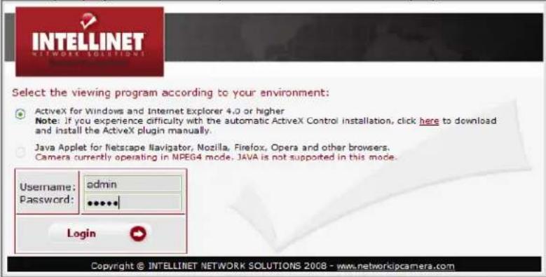
2 Enter the proper User ID and Password and then press "Login" button.
You can select or ActiveX viewer or Java applet viewer, whichever is suitable for your system environment and usage.
To log in as administrator, type in "admin" for both username and password.
To log in as a regular guest user, type in "guest" for both username and password.
You can change the user accounts on the account page in the Administrator menu (see page 21).
Note:
When using MS Internet Explorer and ActiveX, the Internet security settings must be set to low or medium. High security settings can prevent the execution of the ActiveX control. Users of JAVA enabled Web browsers do not need to adjust any security settings.
Access Methods
You can select one of the following two viewers.
Java Applet Viewer
The Java applet viewer operates on Internet Explorer or Netscape.
It displays the main viewer page using Java.
With this viewer, you can use all the functions provided with this software

The Frame rate is lower than for the other viewers
If the viewer does not operate correctly, install or activate Java as follows.
If you are using Internet Explorer
Select "Tools" from the menu bar of Internet Explorer, then select Internet Options and the Advanced tab, and check either "Microsoft VM" or "Java (Sun)" (Microsoft VM recommended).
Then restart Internet Explorer.
Users of any other Web browser; e.g., Firefox, Mozilla, Safari or Konqueror, need to have JAVA installed on the computer. JAVA can be downloaded for free from www.java.com.
ActiveX viewer
The ActiveX viewer is designed for users of Microsoft Windows and MS Internet Explorer. Compared to Java, ActiveX offers better frame rates and functions.
When you log in to the camera for the first time, the security warning appears. Click Yes to install the ActiveX control.

If 'Automatic Configuration' is enabled in the local Area Network (LAN) settings on Internet Explorer, the case may not be displayed. In this case, disable 'Automatic Configuration' and set the Proxy server manually. Setting the Proxy server, consult your network administrator.
Main Live View Page
After you log in, the live view page is displayed. This section briefly explains the functions of the controls on the main viewer page.
Live View Page
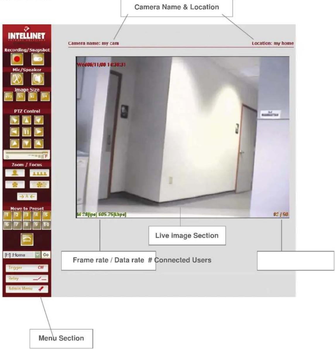
Menu Section

Recording / Snapshot
These buttons activate recording of streaming video (DivX) or still images (BMP).
AVI Recording
Click the record button to start recording
Type the file name and specify the destination of the video file and click "save". The recording now begins. The camera creates a new file once every 10 minutes until you press the record button again or until your computer runs out of disk space.
Take Snapshot
Click on the camera button and specify the location and file name of the snapshot and click "save". The camera saves a BMP still image.

Mic / Speaker (only models with Audio support)
These buttons activate the audio functions of the camera. The microphone symbol activates the PC microphone and allows you to send audio data back to the camera. The speaker symbol enables or disables the audio playback of data sent from the camera to your computer. These buttons may not be active, depending on the user account settings.

Expansion
The digital zoom function allows you to change the image size of the live image in the Web browser. You can chose among 0.5x, 1x, 2x and 4x magnification. Please note that this function does not change the physical resolution of the image. It only provides a digital zoom that electronically resizes the image, which can lead to decreased quality of the picture.

Panning and Tilting
You can pan and tilt the camera using the 8 direction arrow buttons.
Click to stop moving the camera. Observe the monitor image and click the arrow button indicating the direction in which you want to move the camera. Hold down the arrow button to move the direction of the camera continuously.
Adjust the movement speed
When using a high zoom factor, it is difficult to control the movement. Control the speed of the movement with this slider. Move to position "S" to slow down the movement and to position "F" to speed up the movement.
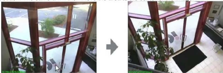
Panning and Tilting by clicking the Monitor Image with the mouse
You can operate panning, titling and zooming of the camera by clicking with the mouse on the monitor image. Left click the area you with to see centered, then move the mouse pointer to the center of the image and release the left button. The camera will then move the area to the center of the image.
natural_image
Two-panel photo showing a window with green plants and a wooden frame, connected by an arrow (no visible text or symbols)
Zoom In / Out
Control the zoom factor of the image.

Focus In / Out
Click to adjust the focus manually. By default, the Auto Focus option is enabled, but you can manually take control of the focus. When you move the camera to a different position with the arrow buttons, the auto focus mode is automatically re-engaged.

Auto Focus
The camera automatically adjusts the image focus (recommended use).
![Move to Preset 1 2 3 4 5 6 7 8 9 10 [P9] :street](/content/2026/05/1141870/images/3c9a94b22f0d95f90ab9c2bd5093e0ea445ac26853f35aa34af923e3893275fe.jpg)
PTZ Control Field
It is possible to move the camera to pre-programmed positions. You can access 10 presets directly through buttons 1 – 10. You can access all 20 programmed presets by selecting P1 – P20 from the drop-down list. By default, this list is empty, as no presets are programmed. For information on setting up preset positions, see "PTZ control" on Page 21.

Tour / Patrol Mode
If you have programmed a sequence of PTZ presets, you can activate the "Guard Tour" by clicking on this button. When the tour mode is active, the High-Speed Dome Camera will continuously move from one
position to the next and loop through the programmed presets. To stop the tour, press 📄 button in the center of PTZ control field.

Relay closed / Open
Click this button to manually start and stop a connected device; e.g.,, a light switch. The device must be connected to the internal terminal block of the camera (see Installation Guide for details). Only authorized users can activate this function.

Trigger On / Off
This button activates trigger settings of the camera manually.
Once you press "Trigger On" the configured trigger condition and setting will be activated (e.g., an e-mail will be sent, an AVI file will be uploaded via FTP).

Admin Menu
Displays the Administrator menu. (See "1.1 Configuring the Network Speed Dome camera" on page 15) The link is only available for the authorized administrator.
Configuring the High-Speed Dome camera
This section describes how to configure the Network Speed Dome Camera and is intended for the product Administrator, who has unrestricted access to all Setup tools.
Overview of the Administrator Tools
The table below provides an overview of the Administration tools:
| Basic | Network, Dynamic DNS, Date and Time, Video, PTZ Setup |
| User Account | Administrator, General User |
| Event Config | Event Server, Event Setting, Trigger Condition |
| Advanced | Layout, Security, Expert Settings, Privacy Zone |
| Maintenance | Initialization, Info & Upgrade |
| Support | Get help, Product Info |
| Live View | Live View page |
Network
All network-related settings can be defined here.
![INTELLINET NETWORK SETTINGS Device Name High Speed Dome Network Address Static IP Address Dynamic IP Address (via DHCP Server) IP, Subnet mask, Gateway Configuration IP address: 192.168.0.55 Subnet mask: 255.255.255.0 Default gateway: 192.168.0.1 DNS Configuration Primary DNS: 203.248.252.2 Secondary DNS: 164.124.101.2 Web, Video, Upgrade and PTZ Server Port Configuration Web server port: 80 [80 or 1024..65535] Video server port: 50001 [1024..65535] Upgrade server port: 51000 [1024..65535] Control server port: 52000 [1024..65535] Service Configuration Options for notification of IP address change: Settings... Save Cancel](/content/2026/05/1141870/images/7340e5a6694a77238cb93114d6c8f81f607f470f3c065547c44a50aef9c0ccd1.jpg)
Device Name
Enter a device name for the camera. The camera shows up in your network under this name. The name also shows up in your DHCP Server log, should you decide to set the Network Address to "Dynamic IP Address" (see below).
Network Address
The IP address of the camera can be set automatically via DHCP (the camera receives its IP Address information from a DHCP Server in your network; e.g.,, a router), or you can set up the IP information manually. Setting up the IP Address manually requires knowledge about TCP/IP networks.
IP, Subnet mask, Gateway Configuration
If you are using a fixed IP address, you must also enter the correct subnet mask and default gateway. (If you have trouble configuring network system information, ask your network administrator.)
DNS Configuration
DNS (Domain Name Service) provides the translation of host names of IP addresses on your network.
Primary DNS – Type in the IP address of the primary DNS server.
Secondary DNS – Type in the IP address of the secondary DNS server (optional).
Web, Video, Upgrade and PTZ Server Port Configuration
Type the port number for each server port within a limit. Normally it is not necessary to make any changes to the port settings.
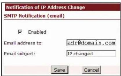
Service Configuration – The camera can send you an e-mail whenever the IP Address of the camera changes (e.g.,, you have set up a dynamic IP Address for the camera). Click on "Settings ..." to open a window which lets you specify the e-mail address.

In order to use this function, the SMTP Server needs to be set up first. Refer to the chapter "Event Config / Event Server". If you use a domain name as the SMTP Server — e.g., smtp.mydomain.com — you also need to setup correct DNS Servers (see above). If the server is entered with the IP Address only, no DNS Servers are required.
Dynamic DNS

Your Internet Service Provider (ISP) provides you with one public IP address. The address you get may be static, meaning it never changes, or dynamic, meaning it's likely to change periodically. Just how often it changes, depends on your ISP. If your IP Address changes periodically, you want to use the DDNS Service (free service offered a www.dyndns.org) to obtain a static address for your dynamic IP.
Use this page to configure Dynamic DNS settings.
Service Use
Check "Enable" when you use Dynamic DNS server.
IP, Subnet mask, Gateway Configuration
Dynamic DNS URL – Type the IP address or URL (leave www.dyndns.org).
ID & Password: Type in your DYNDNS User ID and password. Those are the same values you need to enter when logging in to your personal account on dyndns.org.
Camera URL: Type in the dynamic DNS host address you have registered; e.g., mycamera.dyndns.org.
Status: The camera displays the status of the DYNDNS update.
Click "Save" to save the settings.
Date and Time
![INTELLINET Date and Time Current Camera Time Date: 2006-11-23 Time: 14:15:49 Time configuration Set manually Date: 2006-11-23 [yyyy-mm-dd] Time: 14:15:46 [hh:mm:ss] Automatically synchronized with NTP server NTP server: 207.46.130.100 Time Zone: GMT+09:00 Seoul Adjust clock for Daylight Saving Time Enable Start Day: July Day: 1 End Day: August Day: 30 Save Cancel](/content/2026/05/1141870/images/718a7422ba0d8c3fb6141a4ac17117807a06bf00e351d7f43ccfe6df48472741.jpg)
Current Camera Time
Displays current date and time information based on the settings below.
Time Configuration
(x) Set Manually
You can enter yyyy-mm-dd (year-month-day) for date and hh:mm:ss (hours:minutes:seconds) for time. Manual time configuration is required if the camera is unable to make a connection to an NTP server, perhaps because the camera has no access to the Internet and no local NTP Server is present.
(x) Automatically synchronized with NTP server.
Synchronizes the camera's time with that of the NTP (Network Time Protocol) server. This is the recommended setting, as it makes sure that the time of the camera is always current.
NTP server
Type the host name or IP address of the NTP server, up to 20 characters. A list of free NTP Servers can be found at http://www.ntp.org.
Time Zone
Select the time zone which best represents the location of the camera.
Adjust clock for Daylight Saving Time
Enter the start day and end day of Daylight Saving Time if desired.
Click on the "Save" button to submit the settings to the camera.
Video
All video-related settings can be configured on the page below.
![INTELLINET BASIC » Network » Dynamic DNS » Date and Time ✓ Video » Ptz Control USER ACCOUNTS EVENT CONFIG ADVANCED MAINTENANCE SUPPORT Live View Video Dual mode Streaminging Enable Disable Video format MPEG4 JPEG Image size, Image quality, Image rotation Image size: 720x480 VBR CBR Frame rate: 30 fps Image quality(VBR): Level 4 Image rotation: No flip Bit rate(CBR): 100 [3000 kbps] De-Interace function Enable Disable Color control Brightness: 128 [0..255] Contrast: 128 [0..255] Saturation: 128 [0..255] Hue: 0 [0..128] Direct Image Access Enable Disable Image name: image.jpg Example: http://ipaddress/jpg/image.jpg Save Cancel Load default values](/content/2026/05/1141870/images/53d76b3209a64c8743d0896734dfb8576ce02158ebe6fa0232d8283fc2ec4605.jpg)
Dual Mode Streaming
When this is activated, the camera will send out MPEG4 video and Motion-JPEG video at the same time. This can be useful if you want to utilize a third-party video surveillance solution which uses Motion-JPEG and at the same time want to benefit of the MPEG4 compression for your Web browser based access. When dual mode is activated, the camera slits the available video frame rate in two: 15 fps for MPEG4 video and 15 fps for M-JPEG video.
Video Format
You can choose between MPEG4 compression (default) and JPEG compression. The MPEG4 compression is the ideal choice if you want to view the live image of the camera over a remote network connection and you want to get the best possible frame rate out of the camera. MPEG4 compression generates a smaller video stream, which allows for higher frame rates.
With activated JPEG compression, the frame rate drops for connected users; however, depending on the compression settings, the image quality is slightly better than with MPEG4 compression. JPEG compression is also required by many third-party video surveillance applications which don't support MPEG4 cameras (yet). Only if the JPEG compression mode is activated can you utilize the "Direct Image Access" feature described below. The "Direct Image Access" feature is useful when integrating the live video of the High-Speed Dome Camera in video surveillance applications, or to show the image on a Web site. This function is only available in JPEG streaming mode.
Image Size, Image Quality, Image Rotation
Image Size: Select the image resolution from the drop-down list. Possible values are: 720x480, 640x480, 720x240, 640x240, 352x240 and 320x240.
Frame Rate: FPS stands for frames per second, or images per second. To conserve bandwidth, you may lower the overall maximum frame rate of the live video. Select 25/30 for the best possible frame rate.
Image rotation: Flip the image in your Web browser. Note: This setting does not have any effect on videos transmitted via FTP or E-mail.
VBR - CBR:
With activated MPEG4 compression mode, you can select either VBR mode or CBR mode.
Variable bit rate (VBR) varies the amount of output data per time segment. VBR allows a higher bit rate (and therefore more storage space) to be allocated to the more complex segments of media files while less space is allocated to less complex segments. This means that the video stream size is constantly adjusting to the video material currently being transmitted. If there is a lot of motion in the video and a lot of details, the bit rate goes up and the frame rate drops. If the image shows little motion or areas with little detail (walls, etc.), the bit rate goes down and the frame rate goes up. VBR produces a better quality-to-space ratio compared to an equivalent CBR algorithm and is therefore the recommended option.
Constant bit rate (CBR) means that the rate at which a codec's output data should be consumed is constant. CBR is useful for streaming multimedia content on limited-capacity channels since it is the maximum bit rate that matters, not the average, so CBR would be used to take advantage of all of the capacity. CBR would not be the optimal choice for storage, as it would not allocate enough data for complex sections (resulting in degraded quality) while wasting data on simple sections.
Image quality (VBR): Select the image quality level of the video output. Select Level 1 for the best possible quality and Level 28 for the best possible compression at the highest possible frame rate. A good value is Level 4. It generates a full-motion video (30 fps at highest image resolution) over a 100 Mbps network connection with a very good image quality. Higher values (Level 3, 2, 1) increase the image quality even more, but at the cost of frame rate.
Bit rate (CBR): Specify the bit rate. Possible values range from 1 (30 kbps = highest compression, smallest image frame, highest frame rate) to 130 (3900 kbps = lowest compression, biggest image frame, lowest frame rate).
Lowest Bit Rate/Quality -> smallest network bandwidth usage
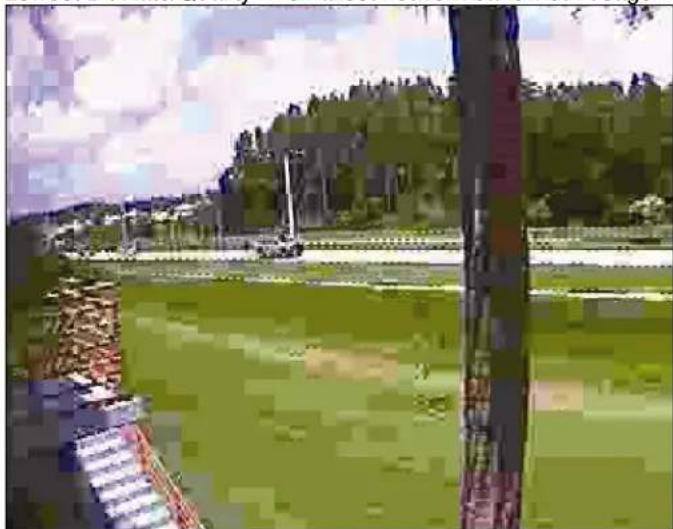
natural_image
Exterior view of a modern office building (no signage)The above image illustrates the effects of lowering the video quality. You have full control over the amount of bandwidth the camera can use, to the point where it becomes difficult to identify any objects in the image due to heavy compression damage.
Highest Bit Rate/Quality -> highest network bandwidth usage:
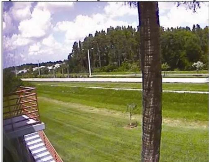
natural_image
Outdoor view of a grassy field with trees and a tree pole, no visible text or symbolsThe effects of compression are minimal at the best image quality settings. The bandwidth usage of the camera at this setting can be up to 10 Mbps.
De-Interlace
Interlaced video is composed of two fields that are captured at different moments in time. When displayed on a typical computer screen, interlaced video frames will exhibit motion artifacts when both fields are combined and displayed at the same moment (today's computer screens are progressive scan monitors which display the image line by line from top to bottom without interlacing). These motion artifacts are visible in the form of horizontal lines. See below:
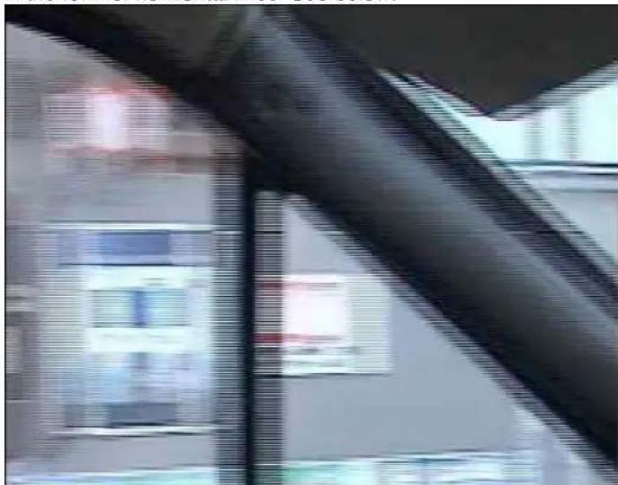
natural_image
Interior view of a building with visible windows and a hand interacting with a metal rod (no text or symbols)De-interlacing reduces the effects of interlacing through methods of interpolation. See below:
natural_image
Interior view of a refrigerator with visible refrigerators and refrigerators inside (no text or symbols)NOTE: De-interlacing is only active for ActiveX / MS Internet Explorer. Java does not support it.
Color Control
You can adjust the Brightness, Contrast, Saturation and Hue settings of the live image. Normally it is not necessary to change these values as the camera automatically adjusts for changing light conditions.
Direct Image Access
This URL allows a direct connection to the internal JPEG image of the camera. It is a useful function to integrate the live video of the camera in third-party video surveillance applications.
Example Address: http://camera_address/jpg/image.jpg
Direct Image Access is only available when JPEG is selected as the video format.
Click on the "Save" button to submit the settings to the camera.
PTZ Control
This screen allows you to store up to 20 presets and to create a guard tour (sequence of steps automatically performed by the camera).
![INTELLINET PTZ control PTZ Protocol D-MAX: 9600bps Basic Network Dynamic DNS Date and Time Video Ptz Control User Accounts Event Config ADVANCED MAINTENANCE SUPPORT Live View Preset setting Monday 08/08-10 08:23 M 9[ms] 420.00[40ps] US / 50 Select preset no.: [H] Enter preset name: Save >> << Delete < Move > [H]: Home [P1]: F.Lakes1 [P2]: F.Lakes2 [P3]: F.Lakes3 [P4]: F.Lakes4 [P5]: Parkinglot1 [P6]: Parkinglot2 [P7]: Stopsign1 [P8]: Stopsign2 [P9]: Stopsign3 [P10]: F.Lakes5 [P11]: F.Lakes6 [P12]: Entrance [P13]: Parkinglot3 Tour setting Enable Disable Display time: 7 seconds[0..3600] at each position: Select preset name: [H]: Home Add >> << Delete You should press "save" before using tour [H]: Home [P1]: F.Lakes1 [P2]: F.Lakes2 [P3]: F.Lakes3 [P4]: F.Lakes4 [P1]: F.Lakes1 [P5]: Parkinglot1 [P6]: Parkinglot2 [P7]: Stopsign1 [P8]: Stopsign2 Save Cancel](/content/2026/05/1141870/images/70a0e83c2f6da87caa0d53f4df8996c284e83faa8e6a163810fd7f7b04407548.jpg)
Preset setting
Follow the steps below.
- Use the PTZ controls below the image to move the camera to the desired position.
- Select a preset no. from the drop-down list ([home] to [P19]).
- Enter preset name (e.g., door) and click "Save >>" to save the preset.
- The new preset appears in the list box.
- Click "Move" to recall any preset you select from the list box.
Tour setting
You can program a patrol tour. That is a sequence of preset positions which the camera cycles through automatically. Check Enable to activate Tour setting.
Display time
This defines the wait time between two positions. Be sure to allow enough time between two steps to allow the camera to completely move from one position to the next. Possible values are from 0 to 600 seconds. We recommend setting the value to at least 5 or higher.
Select preset name
Select a preset name from the drop-down list and click "Add >>". You can choose from up to 20 presets in the preset list. Click "Save" to save the settings and click "<< Tour >>" to check the programmed patrol.
User Accounts
This section describes how to set the ID and password of the Administrator and regular camera users.
Administrator
The administrator has full control over all camera settings.
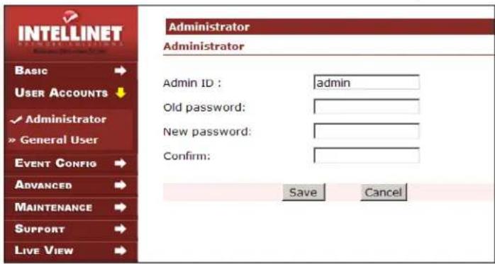
Admin ID
Type an Admin ID (default = "admin") between 4 and 10 characters.
Old password
Type an Old password (default = "admin") between 4 and 10 characters.
New password
Type in a new password between 4 and 10 characters.
Confirm
To confirm the password, type the new password in this field once again.
Click the "Save".

The administrator user is the only user who has access to the camera administration menu. If you lose the password of the administrator account, a hardware reset will be necessary to regain control. This involves either taking the camera apart to get access to the reset switch, or accessing the camera via the serial cable and HyperTerminal. In either case, the camera most likely must be removed from its outdoor location, a potentially very costly operation. Therefore, we highly recommend keeping the password in a safe location!
General User
Set up regular users and define access rights to the Alarm In/Out relay and PTZ control.
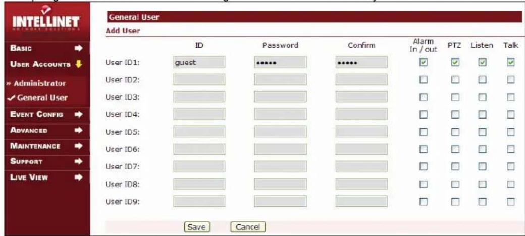
ID: Enter the user name of the account.
Password: Enter the password for this user account.
Confirm: Repeat the password for this user account.
All users have the ability to view the live image.
Alarm in/out
Allows triggering the input / output replay option on the Web browser live view page.
PTZ
Allows control of the camera movement via the PTZ controls.
Listen
Check this box if the user account has access to the audio feed sent from the camera. With this option enabled, the user can click on the speaker symbol on the live video page to hear the audio.
Talk
Check this box if the user account should be able to send audio back to the camera (if speakers are connected to the audio output of the camera).
Click on "Save" to transfer the settings to the camera.
Event Configuration
This section describes how to configure the NETWORK SPEED DOME Camera's alarm handling. The camera can be configured to perform different actions when a defined type of event occurs.
Event Server
E-mail and FTP Server settings.
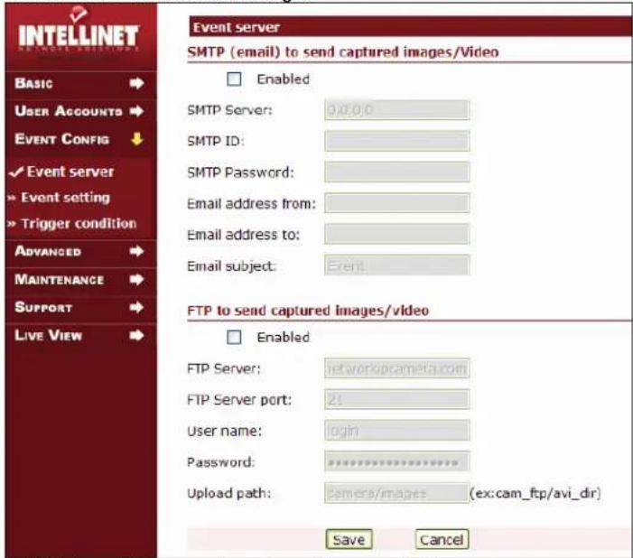
SMTP (email) to send captured images/video
Check Enabled to activate the SMTP (Simple Mail Transfer Protocol) service of the camera, which allows the camera to send you short AVI videos to your e-mail address.
SMTP Server: Enter the SMTP Server address. This is your outgoing e-mail server. If you are not sure what to enter here, contact your network administrator or your Internet Service Provider.
You can enter the IP Address (e.g., 123.456.789.123) or the domain name (e.g., smtp.yourdomain.com) of the SMTP Server.
Email address from: This is the e-mail address the camera uses to send out e-mails. It is the sender e-mail address. It is important to fill this field with contents to make sure the e-mails sent by the camera do not get blocked by other E-mail Servers on the Internet as many E-mail Servers consider e-mail without a sender address to be spam. The e-mail address does not need to be a valid e-mail address as it is only used for sending. An example would be: hsdcamera@domain.com.
Email address to: The e-mail address the camera sends the e-mails to. This can be any standard e-mail address.
Email subject: The title of the e-mail, e.g., "Alert – motion detected!"
SMTP ID: Enter the user ID for SMTP authentication. Most Sendmail servers require the client to authenticate before sending out an e-mail. If you are not sure what to enter here, contact your network administrator, or your Internet Service provider.
Password: Enter the Password for SMTP authentication. If you are not sure what to enter here, contact your network administrator or your Internet Service provider.
FTP to send captured images/video
Check Enabled to activate the FTP (File Transfer Protocol) service of the camera to upload captured images and video to the dedicated FTP server.
FTP Server: Enter the IP Address or domain name of the FTP server. Do not put "ftp://" in front of the IP address or domain name. ftp.intellinet-network.com would be correct, whereas ftp://ftp.intellinet-network.com would be false.
FTP Server Port: Enter the FTP Server port number. The default is 21, which is true for most FTP Servers.
User name: Enter the FTP user name.
Password: Enter the FTP password.
Upload path: Enter the upload path to save the captured image / video data.
When is it required? Whenever you want to upload the images to a subfolder of your FTP User's Home (Root) Directory. Always be sure to enter the directory field without leading and trailing "/" or "\"".
Also, the Directory field is case-sensitive.
Example:
You want to save the images or videos in the subfolder "dome" in the "images" folder. In that case, the upload path must be "images/dome".
Event Setting
An Event setting is as set of parameters describing how and when the Speed Dome Camera is to perform certain actions.
![INTELLINET BASIC → USER ACCOUNTS → EVENT CONFIG ↓ Event server Event setting Trigger condition ADVANCED → MAINTENANCE → SUPPORT → LIVE VIEW → Event setting Trigger enabled Trigger source All day Sun Mon Tue Wed Thu Fri Sat Active time of trigger [0..24] Motion detection ✓ ☐ ☐ ☐ ☐ ☐ ☐ ☐ 0 :00:00 to 24 :00:00 Input port ✓ ☐ ☐ ☐ ☐ ☐ ☐ ☐ 0 :00:00 to 24 :00:00 Timer ✓ ☐ ☐ ☐ ☐ ☐ ☐ ☐ 0 :00:00 to 24 :00:00 Manual trigger ✓ ☐ ☐ ☐ ☐ ☐ ☐ 0 :00:00 to 24 :00:00 Action resulting from event triggering - Upload video/image Upload video/image (* by email, FTP) Capture FPS (MPEG4): 2 fps Maximum capture time(pre+post): 15 seconds Pre-trigger buffer: 0 seconds Post-trigger buffer: 1 seconds Upload format: avi video jpg image Video/image file name: lagune_dom Select the suffix to add the video file name Camera IP Date and time Trigger source File sequence number Action resulting from event triggering - Active output port Active output port When triggered, Output port will be: Opened for 10 seconds [0..60] Action resulting from event triggering - HTTP Request Send HTTP request Specify the address which the camera should open in case of an alarm http://](/content/2026/05/1141870/images/36a0606f15c59f351979367fd76c56c4ec436428ef3d6d2b3885fc0b5d5fb5fd.jpg)
Triggering enabled.
Check this option to enable the Event Trigger Configuration.
Trigger Source
A Triggered event can be activated by four different types of events.
Motion Detection
Check to activate and set the time schedule for this type of event.
Input port
Check to activate and set the time schedule for this type of event.
Timer
Check to activate. This is to send captured image periodically.
Manual trigger
Check to activate. The manual trigger can be activated on the live view page of the Web browser.
Action resulting from event triggering – Upload image/video
Upload image/video (by email, FTP)
Activates the FTP and/or e-mail delivery of captured images.
Capture FPS
Define the frame rate of the captured video/images.
Pre-/Post-Trigger buffer
Set the image capture time before and after event within a limit of maximum image capture time.
The maximum image capture time is calculated automatically by the system according to the settings.
Upload Format
Select AVI VIDEO to receive a video file and JPEG IMAGE to receive a sequence of JPEG still images.
Video/image file name
Specify the filename of the video/image the camera captures.
Select the suffix to add to the video file name
There are four suffixes to add to the video file name.
If you click all, the video file name will be :
EVENT 192.168.0.75 2006 08 14 13 20 44 MD 000
(file name _ IP address _ date and time _ trigger source _ file sequence number)
Action resulting from event triggering – Active output port
This is also useful when you want to activate or deactivate external devices connected to the camera.
Active output port
This button is used to control the digital output port on the camera; e.g., to switch a light on or off.
Check a box and select the type of output port (Closed or Opened) and set the activation time (duration).
Action resulting from event triggering – HTTP Request
Enter a URL and the camera will open the address every time an event occurs. For example, you can use this function to have the camera "ping" your server every 30 seconds as proof that the camera is still online. Enable "timer" as the trigger source, and enter the URL of the server's ping script; e.g., http://www.myserver.com/scripts/cameraping.php.
Trigger Condition
You can configure the trigger condition including, motion detection, input port action and timer condition.
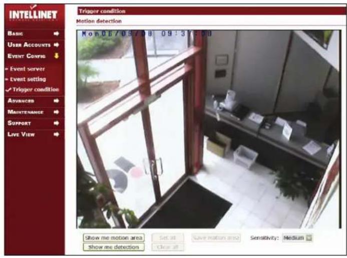
Motion detection
Motion detection is used to generate an alarm whenever movement occurs in the video image. A total of 5 levels can be configured.
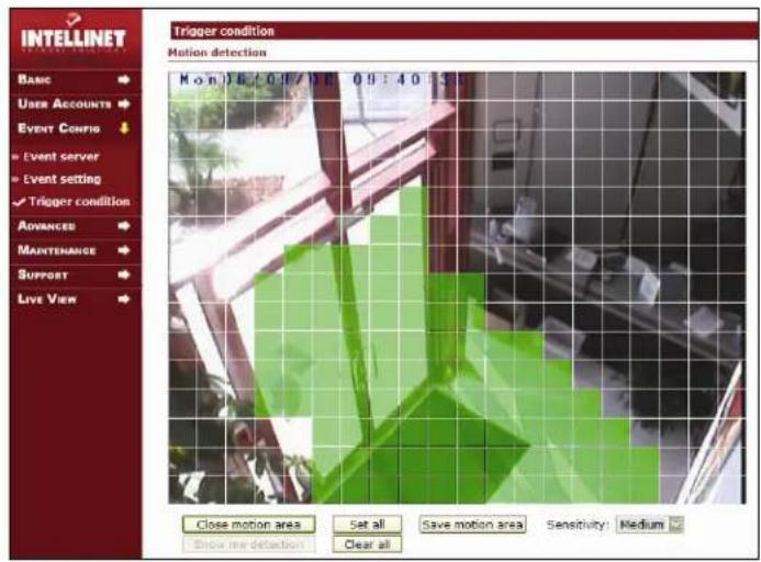
Configuring Motion detection
- Click the "Show me motion area" button at the bottom of the live image and the block zone appears as an overlay on the live image.
- Click to activate / deactivate individual motion detection blocks. Click "Set all" to set the motion area to entire image.
- Select the Sensitivity from the drop-down list from lowest to highest. A higher number means higher sensitivity.
- Click "Save motion area" to complete setting the motion area.
Show me detection
When you click on this button, the camera highlights all areas in which motion occurs. You can use this function to adjust the sensitivity. See the sample image below.
![INTELLINET TRIGGER CONDITION Motion detection Basic User Accounts Event Config » Event server » Event setting ✓ Trigger condition ADVANCED MAINTENANCE SUPPORT LIVE VIEW Kou01/22/07 16:00:5t M 8.0pc [ 432.25]kbps 01:50](/content/2026/05/1141870/images/7a5cdc172861de7a3b60f7009e0123e08169a529ddf3272dbfd3ff2b93be714d.jpg)
The person moving through the image is detected and the detection is indicated by highlighting the corresponding grid blocks.
![Input port action Triggered will be occurred when input port is: Closed Timer every: 10 seconds [0..50] Save Cancel](/content/2026/05/1141870/images/dc8e81dc342b55ab48dab0bb95ac3bd0aa6fb2cb9532b094a260c25ff384424a.jpg)
Input port action
The input port option can be used to connect external alarm devices or sensors to the camera to trigger an action. There are two types of sensors on the market. Some open a circuit in case of an alarm, while others close a circuit. Specify the trigger state of the input port here.
Timer
Set the time to send an image periodically when the event is triggered.
If you set the timer for every 10 seconds, the captured image is uploaded to the dedicated server every 10 seconds. Possible values are 0 – 3600 seconds.
Click to "Save" to transfer the settings to the camera.
Advanced
This section is used for layout options and camera security.
Layout
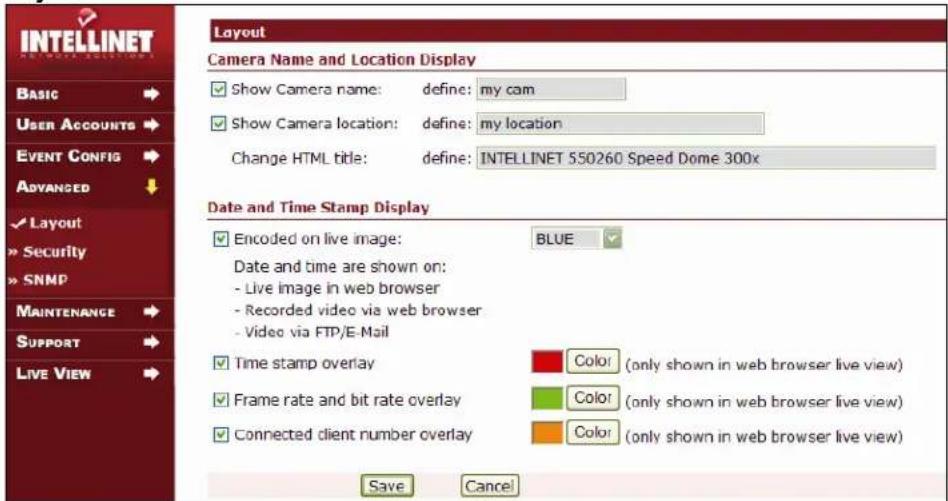
Camera Name and Location Display
Here you can specify the camera name (max. 15 characters) and the location (max. 30 characters). The option "Change HTML title" allows you to change the appearance of the camera in search engines such as Google. So-called "Google hacks" exists to find network cameras on the Internet. Those hacks typically work by finding pages with a matching HTML title. Since this is not necessarily what you would want, you can change the title to something different.
Date and Time Stamp Display
Define additional display options here.
(x) Encoded on live image:
If this option is activated, the date and time stamp is being encoded in the live image and appears in the Web browser live view and all images uploaded via e-mail or FTP. You can define the color of the overlay by selecting the color of your choice from the drop-down box (possible values are: Black, White, Red, Blue. Yellow).
(x) Time stamp overlay:
If this option is activated, the date and time stamp is only visible on the Web browser live view, but not on any images transmitted via e-mail or FTP. While you can activate both of the above options, it is not recommended.
(x) Frame rate and bit rate overlay:
If this option is activated, the current frame and bit rate are displayed in the Web browser live view. The information is not encoded into the video stream and therefore is not visible on video uploaded via e-mail or FTP.
(x) Connected client number overlay:
If this option is activated, the number of currently connected users is displayed in the Web browser live view. The information is not encoded into the video stream and therefore is not visible on video uploaded via e-mail or FTP.
Security & SNMP
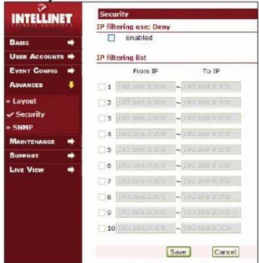
IP filtering use: Deny
Activate the IP Filtering function of the camera. This is a "deny" list, meaning that all IP Addresses you specify will be disallowed access to the camera.
IP filtering list
You can define up to 10 ranges of IP addresses for which you want to deny access to the High-Speed Dome Camera.
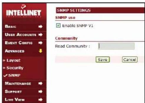
Enable SNMP V1
SNMP stands for Simple Network Management Protocol. Activate this function if you want to use the camera's SNMP function.
Read Community
This is the read-only SNMP community string of your network.
Expert Settings (2008 and newer models only)
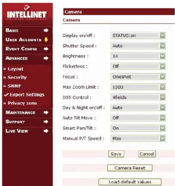
Cameras manufactured in 2008 and later feature expert settings which let you control certain aspects of the camera. Normally it is not necessary to make any changes here. Find the explanations of the different options below. Not all cameras have the same parameters; the features may vary.
Display on/off:
Displays status information such as the preset number on the live image. Set this value to "off" to disable this feature. "Auto" means that status information is only shown while the camera is moving; "on" means that the information is shown all the time.
Expert settings shown for 30x Speed-Dome (10x Speed-Dome has slightly different settings)
Shutter Speed:
This parameter controls the length of time (in sec.) the shutter stays open. The default value is "Auto". In this mode, the camera controls the shutter speed automatically. You can set the shutter speed to a fixed value. 1/120 stands for 1/120 sec. and 1/30000 stands for 1/30000 sec. The shorter the shutter speed, the less light that can reach the CCD image sensor at a given time. This improves the image quality for fast-moving objects, but it also causes the images to get too dark quickly if the ambient light level drops (e.g., at dusk).
Brightness:
This parameter controls the overall brightness of the image. The default value typically gives the best results.
Focus:
This parameter controls the way the camera focuses.
"Manual": No auto-focus. The focus can only be controlled with the focus control buttons on the camera live video page. "One Shot": Focus is operated semi-automatically. When using pan, tilt and zoom functions, the focus is not operated; but when the camera comes to a halt, the focus is operated automatically. "Auto": The camera controls the focus automatically.
Max Zoom Limit:
You can control the zoom factor with this parameter. You can either enable or disable the digital zoom, or, depending on the camera model, you can define the max. zoom factor using values such as x30, x60, etc.
Day & Night on/off:
This parameter controls the camera's video image at nighttime. "Off" disables the black and white mode at night so that the camera continues to send color images at the expense of brightness. "On" activates the black and white mode permanently, even during daylight conditions. "Auto" is the default value. In this mode the camera automatically engages the black and white mode when the light level drops below a certain value and re-engages the color mode when a threshold light level has been reached.
Flickerless:
When pointing a security camera at lighting with a strong, wide and intense range of color (such as fluorescent or mercury vapor light), you will notice that the camera will continually try to adjust to the high color range of the lighting, most commonly referred to as "pulsing". Activating the "flickerless" filter diminishes the problem. If you experience problems as described above, you should enable the filter. Under normal conditions it is not required, however.
Smart Pan/Tilt:
When this is enabled, the camera automatically lowers the PTZ speed when you zoom in allowing a more precise movement control at higher zoom factors.
Manual P/T Speed:
Define the maximum travel speed of the PTZ unit with this option. At "high" setting, the speed is not limited at all and you can move the PTZ unit at 360 degrees per second. "Medium" limits the speed to 90 degrees per second; "low" only provides a travel speed of 40 degrees per second.
Auto Tilt Move
When the camera tilts downward and goes just beyond the vertical position, the dome rotates 180 degrees. When the camera rotates (flips), the camera starts moving upward as long as you continue to hold the camera in the down position.
DSS Control
DSS stands for digital slow shutter. The higher the value, the longer the shutter stays open at nighttime. The positive side of this is that the camera can capture images even if there is very little light. The downside is that activating DSS leads to a lower image quality and a higher noise level in the picture. Values of 2 - 8 fields are typically recommended.
Camera Reset
Clicking this button resets all camera related expert settings to the default values.
Privacy Zone (2008 and newer models only)
The INTELLINET NETWORK SOLUTIONS High-Speed Dome cameras support privacy masking. This is a technology which allows you to "censor" or black out certain areas in the image. Depending on the camera model, you can define between 4 and 16 privacy zones. Privacy masking is an important feature to protect the privacy rights of individuals. It applies to installations in work environments as well as public places, where residential areas need to be protected. Some countries require this functionality in all publicly installed cameras.
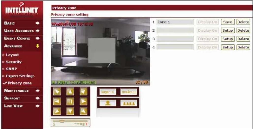
How to define a privacy zone
- Enter a name for the zone (example "Zone 1").
- Click on "Setup".
- Use the PTZ control field to move the camera to the correct position.
- Click on "larger(+) or "smaller (-)" to resize the privacy area.
- Click on "larger(+)" or "smaller (-)" to center the privacy area after you have used the PTZ functions.
- Use the zoom in and zoom out buttons to change the field of view of the live image.
- Use the S-F slider to adjust the PTZ movement speed.
- When you are satisfied with the position of the privacy zone, click "Save".
The screen will look like this:
![Privacy zone Privacy zone setting Wed06/11/08 18:44:38 1 Zone 1 Display On Setup Delete 2 3 4 Display On Setup Delete Display On Setup Delete Display On Setup Delete M 13[bps] 1065.00[bps] 79,150](/content/2026/05/1141870/images/7fd6dda82b902066a3a118384b01c584c9177255ad5d1e2dc043c6d876f21e62.jpg)
- Click "Display On" to activate the privacy zone.
Repeat these steps to set up additional privacy zones.
Maintenance
System Initialization
This page contains a set of tools to perform certain operations.
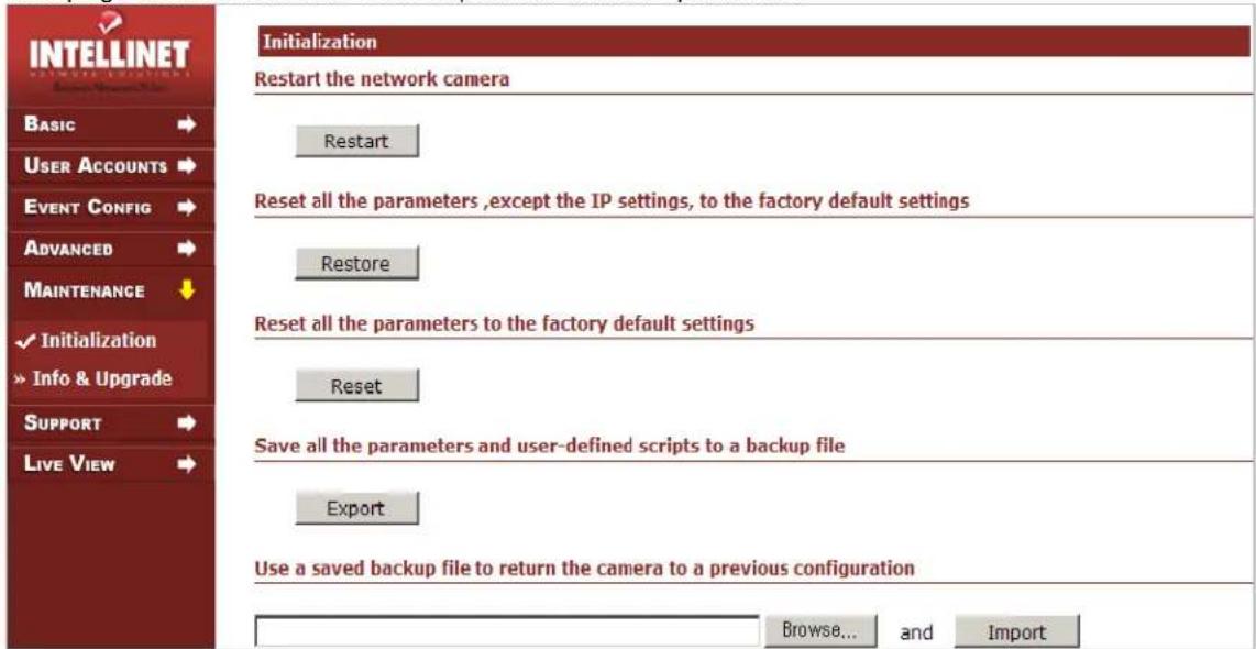
Restart
If the camera is not behaving correctly, you can remotely reboot the camera using this option. No camera settings are overwritten during this operation. The entire restart process takes 30 seconds.
Restore
All camera settings are being set back to factory default values – except for:
- the boot protocol (DHCP or static)
- the static IP address
- the default gateway
- the subnet mask
Reset
Pressing this will return all camera settings to the factory default values (including the IP address). This button should be used with caution!
Export
You can create a dump of the entire configuration and save it on your local hard drive. If you want to restore the configuration at a later time, perform the function below.
Import
Click the browse button to locate the saved backup file and then click the import button to reload the configuration.
Info. and Upgrade
![INTELLINET Basic → User Accounts → Event Config → Advanced → Maintenance ↓ > Initialization ✓ Info & Upgrade Support → Live View → Info. and Upgrade Information Model: 550260 (NTSC) Serial number: ABO214-00042 Firmware (application): 03.03.038 MAC address: 00-19-26-10-00-2A Camera version: 8.5 Upgrade firmware Browse and Upload System log INF 06/09/08 09:24:41 System booting... [code:9 REBOOT_BY_SYSTEM_RESTART]](/content/2026/05/1141870/images/3a604dc5343e54944759854e6fab46bc9bdb5896913739ecd2ecc05cd2f4a09d.jpg)
Information
See the system information for the INTELLINET NETWORK SOLUTIONS High-Speed Dome Camera.
Upgrade Firmware
This function lets you install a new firmware on the High Speed Dome Network Camera. Updated versions can be found at http://www.networkipcamera.com.
Refer to the chapter "Firmware Upgrade Procedure" for further information.
System Log
System log of the camera showing various pieces of information.
Support
HELP
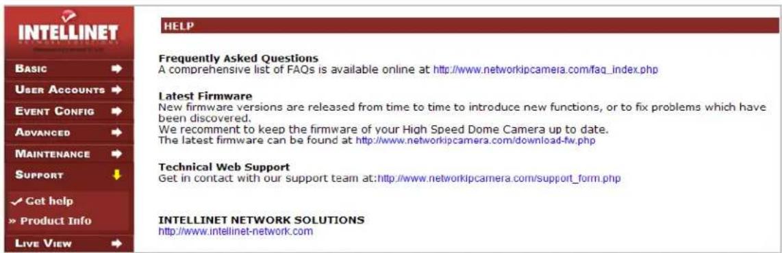
Links to various information sources on the Web.
Product Info
Links to the INTELLINET NETWORK SOLUTIONS Network Camera Web site.
Firmware Upgrade Procedure
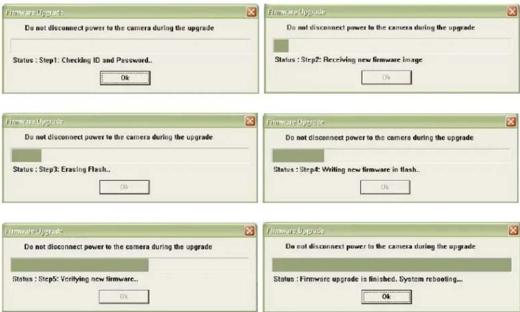
New firmware versions become available from time to time, adding new features and addressing compatibility problems. If you experience technical difficulties with your product, you should check the Web site www.networkipcamera.com to find out if a new firmware version is available. Download the firmware to your computer's desktop and uncompress the ZIP file. Inside the ZIP file you can find a *.frm file. That is the actual firmware file. There are two ways of installing the firmware; using the Web browser and using the camera manager program. Regardless of which way you do it, you must always make sure that the firmware upgrade process is not (!) being interrupted or the camera will be destroyed beyond repair. Cameras which have been damaged during a firmware upgrade because of a lost network connection or power loss during the upgrade are not covered by warranty.
Using the Web browser interface
Connect to the camera with your Web browser and open the Administrator menu. Click on Maintenance -> Info. and Upgrade to open the firmware upgrade page.
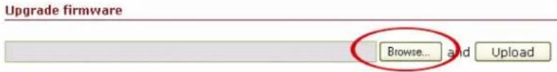
Click on "Browse" and select the firmware file.
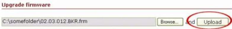
Click on "Upload" to start the upgrade procedure.
Wait for 30 seconds, then click on "OK" to reconnect to the camera.
Using the Camera Manager program
Start the camera manager program from the program CD.
Camera Manager finds all High Speed Dome Network Cameras on your network.
- Select the camera from the list.
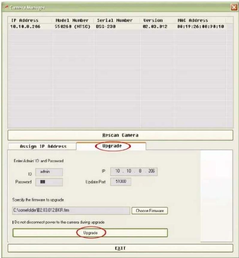
- Enter user ID and password of the administrator account.
- Select the firmware file using the browser button.
- Start the process by clicking on the upgrade button.
- Wait for the process to finish.
- Click on "Rescan Camera" to verify the firmware upgrade was successful.
Simple Multi Viewer
![INTELLINET NETWORK SOLUTIONS Simple Multi Viewer V1.7 CH1 IP: 550260.networkipcamera.com CH2 IP: 67.111.35.12 Wed 01/30/08 10:19:49 Wd 3[fps] 36.75[fps] 01 / 50 Rec. AVI Snapshot On Off Conf CH3 IP: 62.159.227.165 CH4 IP: 123.253.32.35 Rec. AVI Snapshot On Off Conf INTELLINET NETWORK SOLUTIONS January 30, 2008 10 : 13 : 47 Storage location c:\SMV_data HDD Free Space: 8 % View Mode Channel Selector 2 3 4 PTZ Control Zoom / Focus Connect All Disconnect All Video Player Exit](/content/2026/05/1141870/images/9045b51453f1b04f67daa223e5be0d71e9877f6e3057cc6e013e61d7d557e5b6.jpg)
Overview
Simple Multi Viewer (SMV) is a software application which allows monitoring, controlling and recording of up to four INTELLINET NETWORK SOLUTIONS High-Speed Dome cameras.
SMV supports several methods to control the movement of the speed dome:
- Using the SMV user interface: Use the arrow keys and zoom/focus controls.
- You can use the mouse to click a part of the image, causing the camera to automatically center that section; the mouse scroll wheel can be used to zoom in and out.
- SMV supports Windows compatible joysticks*. Joystick buttons one to six can recall the PTZ presets of the camera. The throttle control can be used to zoom in and out. Regular joystick movements translate into Pan-Tilt movements of the camera on the screen. Analog joysticks are supported in that if the joystick is pushed only slightly, the camera movement is very slow, whereas if the joystick is pushed all the way, the movement is very fast.
Minimum System Requirements
Hardware
Intel Pentium 4 with 2 GHz processor
CD-drive
■ 512 MB RAM
- Hard Disk: 10 MB available space for installation
- NTFS file system
- XGA (1024 x 768) or higher resolution monitor
■ 100 Mbps Ethernet with a static IP address
System
- Microsoft Vista, Microsoft Windows XP professional SP2, 2000 (SP4) 2003
■ Server (SP1), Internet Explorer Version 6.0 or later, DirectX 9.0c or later (for MPEG2/4) - TCP/IP support
Installation Procedure
- Insert the CD in the CD-ROM drive and double-click "SimpleMultiViewer.setup" in the CD's root folder.
- Simply follow the Installation Wizard's instruction.
- You will be asked where you wish to install the program. Unless specified otherwise, the program is normally installed in C:\Program Files\Simple Multi Viewer
- Click your way through the Installation Wizard.
- When the installation is finished, open Simple Multi Viewer from Start > All Programs or click the program icon on your desktop:

Simple Multi Viewer.Ink
NOTE:
Both Simple Multi Viewer and MS Internet Explorer utilize ActiveX. If you install new firmware on your camera, sometimes the ActiveX control of your Web browser is also upgraded through an automated upgrade process. In those cases, you have to uninstall the current Simple Multi Viewer and install the updated version from www.networkipcamera.com.
Simple Multi Viewer User Interface
![INTELLINET NETWORK SOLUTIONS Simple Multi Viewer V1.6 CH1 IP: 192.168.0.254 CH2 IP: 192.168.0.102 Thu 2/20/07 11:05:06 CAM-888 Thu 02/24/00 19:12:39 M 28[fps] 513.25[kbps] 02 / 50 ● Rec. AVI Snapshot On Off Conf CH3 IP: 192.168.0.75 CH4 IP: 192.168.0.102 Thu 2/20/07 11:21:32 CAM-888 Thu 02/24/00 19:12:39 M 30[fps] 2007.50[kbps] 02 / 50 ● Rec. AVI Snapshot On Off Conf INTELLINET NETWORK SOLUTIONS December 21, 2007 11 : 00 : 16 Storage location C:\Program HDD Free Space: 72 % View Mode Channel Selector 1 2 4 PTZ Control Zoom / Focus → A ← Connect All Disconnect AI Video Player Exit](/content/2026/05/1141870/images/9bf05caac9de6409344d1aafe421bd82310e5511b5a0b787674828d8688dd0a3.jpg)
Interface Functions
Recording and Snapshot
These buttons activate the recording of streaming video (Divx)
or still images (BMP). Click "Rec. AVI" to start the recording. Enter the filename and then click "OK." The camera creates a new file once every 10 minutes, until "Recording" is clicked again or until your computer runs out of disk space. (The available hard disk memory should be more than 800 MB).
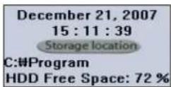
Storage Location
Click "Storage location" to specify the destination of the video file.
Take Snapshot
Click on the camera icon ("Snapshot") and specify the location and filename of the snapshot. Click "Save" to save a BMP still image.
On/Off
These buttons activate or deactivate the connection to the camera.
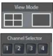
View Mode
You can select view mode as single or 4ch multi view.
Channel Selector
Click to select the channel or simply click on the image on each channel.
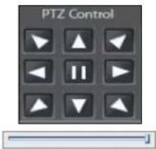
PTZ control
You can pan and tilt the camera using the eight directional arrow buttons. Click and hold the arrow button which indicates the direction you want to aim the camera.
Adjust the Movement Speed
Control the speed of the movement with the slider below the arrows. Left position = slowest, right position = fastest.
Mouse Auto-Center function
You can operate panning, titling and zooming of the camera by clicking the mouse on the monitor image. Click on the monitor image and the camera moves so that the clicked portion goes to the center of the display.
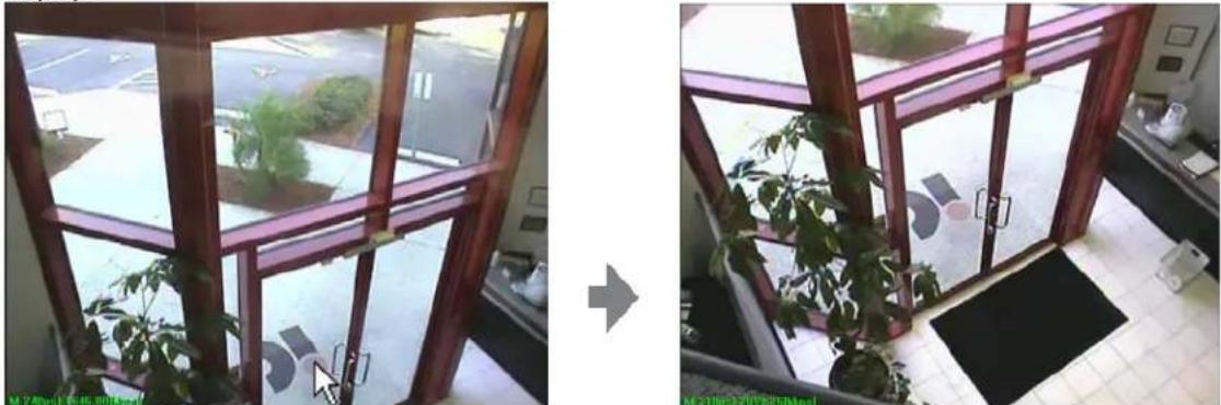
natural_image
Interior view of a modern building with large windows and a potted plant, showing no visible text or symbols.Click a part of the image to center it.
Zooming with the Mouse scroll wheel
You can adjust the zoom level by turning the scroll wheel forward and backward.
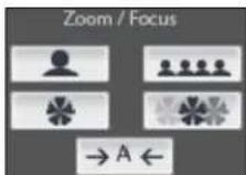
Zoom In/Out
Control the zoom factor of the image.
Focus In/Out
Click to adjust the focus manually. By default, Auto Focus is enabled, but you can manually take control of the focus. When you move the camera to a different position with the arrow buttons, Auto Focus is automatically re-engaged.
Connect All / Disconnect All
You can connect or disconnect all cameras at the same time with these buttons.
Video Player

Click "Video Player" to play the recorded video image or execute "SMV player"

SMV Player.Ink
on your PC.

Video Storage Path Browse
Click on "Browse" to define the location of the videos. This location is the video player's location. It does not control the location of the recording, which is defined under Storage Location.
Snapshot
First, pause the video clip and then take a snapshot to get a BMP image.

Click to print the snapshot image.
Select Camera

This list shows the IP address of cameras that save the video image.
Select Date

This drop-down list shows the recordings by date.
Delete Video
Choose the video data from the list and click to delete it.
Exit
End Simple Multi Viewer.
Appendix
Troubleshooting
This appendix provides useful information to help you resolve any difficulty you might have with your camera. Symptoms, possible causes and remedial actions are provided within a quick reference table.
PINGing your IP Address
By sending a packet to the specified address and waiting for a reply, the PING (Packet Internet Groper) can determine whether a specific IP address is accessible; it also provides a particularly useful method for confirming addressing conflicts with your camera on the network.
Having disconnected your camera, follow the instructions below in association with Symptoms, Possible Causes and Remedial Actions, and run the PING utility to troubleshoot TCP/IP problems on your network.
- Start a DOS window
- Type ping x.x.x.x, where "x.x.x.x" is the IP address of the camera
- The subsequent replies will provide an explanation as to the cause of the problem. Replies can be interpreted as defined in the table below:
PING Reply
Interpretation and recommendation
| bytes = 32 time = 2 ms The | IP address is already used and cannot be used again. Your must obtain a new IP address |
| Destination host unreachable Network IP Camera is not accessible within your subnet.You must obtain a new IP address | |
| Request timed out This IP address is not used by anyone and is available for use with your Network IP Camera | |
Symptoms, Possible Causes and Remedial Actions
Symptoms
Possible causes
Remedial actions
| Problem Possible | Causes Remedial Actions | |
| Setting the IP address | The camera is Located on a different subnet | If the IP address intended for the camera and the IP address of your PC are located on different subnets, you will not be able to set the IP address. Contact your network administrator for an IP address on the same subnet as the computer you are performing the installation from. |
| The IP address is being used by another device | Disconnect the power from the camera. Run the Ping command (in a Command/DOS window, type "ping" and the IP address of the unit).If you receive: Relay from: bytes = 32; time=10ms... - this means that the IP address may already be in use by another device on your network. You must obtain anew IP address and reinstall the unit.If you receive: Request timed out – this means that the IP address is available for use with your camera. In this case, check all cabling and reinstall the unit. | |
| Cannot access from a Web browser | Cannot log in If the camera has been configured to use HTTPS, check that the protocol in the URL used to access the unit is correct. You may need to type this in manually (e.g., http or https) in the browser's address field. | |
| The IP address has been changed by DHCP | 1) Move the camera to an isolated network or to one with no DHCP or BOOTP server. Set the IP address again, using an IP utility or the ARP Ping commands.2) Access the unit and disable BOOTP and DHCP in the TCP/IP settings. Return the unit to the main network. The unit has a fixed IP address that will not change.3) As an alternative to 2), if a dynamic IP address via DHCP or BOOTP is required, select the required service and then configure the IP address change notification from the network settings. Return the unit to the main network. The unit will now have a dynamic IP address, but will notify you if the address changes. | |
| Other network problems | Test the network connection to another network device, then Ping that device from your workstations. | |
| Video Image Problems | Missing images in uploads | This can occur when trying to use a larger image buffer than is actually available. Try lowering the frame rate or the upload period. |
| Slow image update Configuring hi-res images, high frame rate, etc. will reduce the performance of the camera. | ||
| Slow Performance Slow performance may be caused by heavy network traffic, too many users with access to the unit, low-performing client, use of features such as Event handling, image rotation, etc. | ||
| Too dark or light image | Re-configure the video settings. | |
| Bad snapshot images | Display incorrectly configured on your workstation | In Display Properties, configure your display to show at least 65000 colors; i.e., at least 16-bit. Using only 16 or 256 colors on your display will produce dithering artifacts in the image. |
| No image | Faulty installation Check all cables, plugs, contacts and connections. | |
| Wrong IP address Check the IP address (with an IP utility). | ||
| Faulty data transmission within the LAN | Check data transmission with the ping command. | |
| Accessible locally, but not externally | Firewall protection Check the Internet firewall with your system administrator. | |
| Default routers required | Check if you need to configure the default router settings. | |
| Only half the image is displayed | Lower version of IE Upgrade Internet Explorer to version 6.0 or higher. | |
| The password has been forgotten | Press the Factory Default Reset button to reset the camera to default. Set up the camera again. | |
| The camera IP address and port number have been forgotten | Find the IP address by using the IP install utility. You can find the IP address easily unless the operating PC is not on the same gateway with the unit. | |
| The Password has been forgotten | Press the Factory Default Reset button to reset the camera to default. Set up the camera again. | |
| The pan, tilt, zoom, focus, click to center and preset features do not work | Your PC is not connected to the camera | Click "Refresh" on the Web browser. Confirm that the image refreshes, and that you can operate the pan/tilt/zoom/focus functions. |
| The camera is not turned on | Turn the camera on. | |
| Multiple users are operating camera simultaneously | Wait for a moment and then access the camera again. | |
| The pan/tilt/zoom/focus reaches on the end of its range | Confirm that the end display is displayed on the operation bar. | |
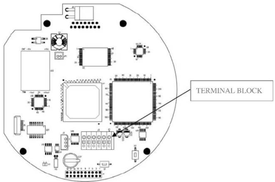
Terminal Block
This section describes the pin out provided by the connection module consisting of:
1 digital output
- I digital input
RS-485 R/TX
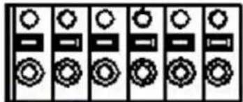
natural_image
Pure electrical circuit lines without any symbolsPin NO. 1 2 3 4 5 6
The input/output is used in applications for event triggering, time-lapse recording, alarm notification via e-mail, picture storage to FTP locations.
- Input – For example, an infrared sensor that can be activated from Trigger on/off from the live view page or as an action to an Event condition setting.
- Output – For example, an alarm device light that can be activated from the relay output button on the live view page or as an action in the Event Trigger settings.
| NO Function Description | ||
| 1 | Digital In (+) Input for the external input devices (+) | |
| 2 | Digital In GND (-) Input for the external input devices (-) | |
| 3 | Digital Out (+) Output to the external output devices (+) | |
| 4 | Digital Out GND (-) Output to the external output devices (-) | |
| 5 | RS-485 R/TX(+) Control signal pin for external keyboard controller(R/TX+) | |
| 6 | RS-485 R/TX(-) Control signal pin for external keyboard controller(R/TX-) | |
- Press the tap on the top of the pin (see the table above to determine which pin to use)
- Push the cable into the connector and secure it by loosening the tap.

Digital Input - connect to GND to activate or leave floating (unconnected) to deactivate.
Digital Output - Max. load 50 mA, max. voltage 24 V DC. An open-collector NPN transistor with the emitter connected to pin 4 (GND). If used with an external relay, a diode must be connected in parallel with the load for protection against any voltage transients.
Schematic Diagram
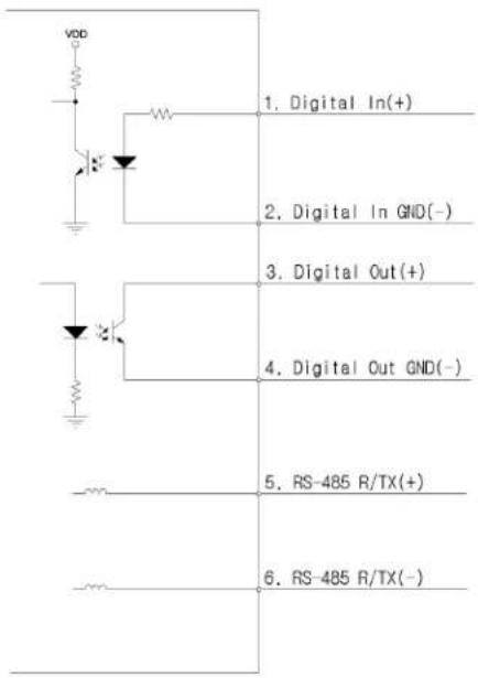
You should disassemble the speed dome network camera to use terminal block. Refer to the installation guide how to disassemble the speed dome network camera.
Dynamic DNS Registration
Your Internet Service Provider (ISP) provides you with one IP address which you use to connect to the Internet. The address you get may be static, meaning it never changes, or dynamic, meaning it's likely to change periodically. Just how often it changes depends on your ISP. A dynamic IP address complicates remote access since you may not know what your current WAN IP address is when you want to access your network over the Internet. The solution to the dynamic IP address problem comes in the form of a dynamic DNS service.
The Internet uses DNS servers to look up domain names and translates them into IP addresses. Domain names, such as www.intellinte-network.com, are just easy-to-remember aliases for IP addresses. A dynamic DNS service is unique because it provides a means of updating your IP address so that your listing will remain current when your IP address changes. There are several excellent DDNS services available on the Internet. An excellent DDNS services is www.DynDNS.org. You'll need to register with the service and set up the domain name of your choice to begin using it. Refer the home page or the service for detailed instructions.
A DDNS service works by uploading your WAN IP address to its servers periodically. Your gateway-router may support DDNS directly, in which case you can enter your DDNS account information into your router and it will update the DDNS servers automatically when your IP address changes. Consult your router's documentation for more information. If your router does not support DDNS, you can run a small client utility on any PC on your network, which will perform the updating. The client utility is usually provided for free by the service.
Check the service's Web page for further information, terms and conditions.
How to use DynDNS DDNS server
A. Access the homepage (www.dyndns.org).
B. Click "Sign Up Now" and then create your account unless you already have it.
C. Log in with a registered ID and Password.
D. Go to "Services -> Dynamic DNS" and then click "Add Dynamic DNS".
E. Enter a host name of your choice and select the host type from drop-down list.
F. Enter an IP address and leave the other empty.
Click "Add Host" to complete.
Go to "Account → My Services" to check your service, service setting and so on.
Technical Specifications
High Speed Dome Indoor/Outdoor Network Camera (550277)
MPEG4, CCD, Day/Night, Temperature Controlled, PAL
Standards
• IEEE 802.3 (10Base-T Ethernet)
• IEEE 802.3u (100Base-TX Fast Ethernet)
• IP66 (Ingress Protection)
General
• Supported image resolutions: 720 x 576, 640 x 576, 720 x 288, 640 x 288, 352 x 288, 176 x 144
- Protocols supported: HTTP, TCP, UDP, SMTP, UDP, FTP, ARP, DNS, DynDNS
• Certifications: FCC Class A, EMC: EN61000-3-2, EN610003-3 EN55022, EN55024
Image Sensor and Lens Specification
• 1/4" SONY Super HAD CCD sensor
• Total pixels: 410K, 811 (H) x 508 (V)
• Horizontal Resolution, more than 540 TV Lines
• S/N ratio: More than 50 dB
• Video output: 1.0 Vp-p (75 Ohms, Composite)
• Automatic white balance control
• Image control, Brightness, Contrast, Saturation, Hue
• Minimum illumination color: 0.7 Lux at 30IRE / 0.1 lux (DSS)
• Minimum illumination black and white: 0.1 lux (Day & Night Mode) / 0.0007 lux (DSS)
- Shutter speed: 1/120 - 1/60,000 sec.
• Focal length 3.3 - 99 mm
• Pan rotation angle: 360°
• Tilt rotation angle: -2^ - 90^
- Angle of view: approx 58.17° (Wide), approx 2.2° (Zoom)
• Maximum Relative Aperture F1.6
Environmental
- Dimensions:
- Height: 302 mm (11.8 in.)
- Diameter: 216.8 mm (8.5 in.)
- Weight:
- Housing and dome drive unit: 3.0 kg (6.6 lbs.)
- Wall mount bracket: 0.9 kg (1.9 lbs.)
- Operating temperature: -40 - 60^ (-40 - 140°F)
- Operating humidity: 0 – 90% RH, non-condensing
- Storage temperature: -5 - 50^ (23 - 122°F)
Power
• External power adapter:
- Input: 240 V AC, 50 Hz (US Version: 110 V AC, 60 Hz)
- Output: 24 V AC, 1.5 A
• Power consumption: 18 Watts (maximum)
System Requirements
• Windows 2000, XP, Vista
• Computer with network connection
- Web browser support:
- MS Internet Explorer 5.0 or higher (ActiveX)
- Netscape Navigator, Mozilla, Firefox, Opera (Java for JPEG only)
Package Contents
• High Speed Dome Indoor/Outdoor Network Camera with external cable
- User manual
- Wall mount Bracket
- Software CD (Camera Manager Program for IP installation, upgrade and user's manual)
High Speed Dome Indoor/Outdoor Network Camera (550260)
MPEG4, CCD, Day/Night, Temperature Controlled, NTSC
Standards
• IEEE 802.3 (10Base-T Ethernet)
• IEEE 802.3u (100Base-TX Fast Ethernet)
• IP66 (Ingress Protection)
General
• Supported image resolutions: 720 x 480, 640 x 480, 720 x 240, 640 x 240, 352 x 240, 320 x 240
- Protocols supported: HTTP, TCP, UDP, SMTP, UDP, FTP, ARP, DNS, DynDNS
• Certifications: FCC Class A, EMC: EN61000-3-2,EN610003-3 EN55022,EN55024
Image Sensor and Lens Specification
• 1/4" SONY Super HAD CCD sensor
• Total pixels: 410K, 811 (H) x 508 (V)
• Horizontal Resolution, more than 540 TV Lines
• S/N ratio: More than 50 dB
• Video output: 1.0 Vp-p (75 Ohms, Composite)
• Automatic white balance control
• Image control, Brightness, Contrast, Saturation, Hue
• Minimum illumination color: 0.7 Lux at 30IRE / 0.1 lux (DSS)
- Shutter speed: 1/120 - 1/60,000 sec.
• Focal length 3.3 - 99 mm
- Pan rotation angle: 360^
• Tilt rotation angle: -2° - 90°
- Angle of view: approx 58.17° (Wide), approx 2.2° (Zoom)
• Maximum Relative Aperture F1.6
• Minimum illumination black and white: 0.1 lux (Day & Night Mode) / 0.0007 lux (DSS)
Environmental
- Dimensions:
- Height: 302 mm (11.8 in.)
- Diameter: 216.8 mm (8.5 in.)
- Weight:
- Housing and dome drive unit: 3.0 kg (6.6 lbs.)
- Wall mount bracket: 0.9 kg (1.9 lbs.)
- Operating temperature: -40 - 60^ (-40 - 140°F)
- Operating humidity: 0 – 90% RH, non-condensing
- Storage temperature: -5 - 50^ (23 - 122°F)
Power
- External power adapter:
- Input: 240 V AC, 50 Hz (US Version: 110 V AC, 60 Hz)
- Output: 24 V AC, 1.5 A
• Power consumption: 18 Watts (maximum)
System Requirements
• Windows 2000, XP, Vista
• Computer with network connection
• Web browser support:
- MS Internet Explorer 5.0 or higher (ActiveX)
- Netscape Navigator, Mozilla, Firefox, Opera (Java for JPEG only)
Package Contents
• High Speed Dome Indoor/Outdoor Network Camera with external cable
- User manual
• Wall mount Bracket
- Software CD (Camera Manager Program for IP installation, upgrade and user's manual)
Mini High-Speed Dome Camera (550451)
MPEG4/M-JPEG, CCD, Day/Night, Audio, PAL
Standards
• IEEE 802.3 (10Base-T Ethernet)
- IEEE 802.3u (100Base-TX Fast Ethernet)
General
• Supported image resolutions: 720 x 576, 640 x 576, 720 x 288, 640 x 288, 352 x 288, 176 x 144
- Protocols supported: HTTP, TCP, UDP, SMTP, UDP, FTP, ARP, DNS, DynDNS
• Certifications: FCC Class A, CE, RoHS compliant
Image Sensor and Lens
• 1/4" SONY Super HAD CCD sensor
• Total pixels: 470K, 795 (H) x 596 (V)
• Horizontal resolution: 500 TV lines (color), 570 TV lines (B/W)
• S/N ratio: more than 50 dB
• Video output: 1.0 Vp-p (75 Ohms, composite)
• Automatic white balance control
• Image control, brightness, contrast, saturation, hue
- Minimum illumination: 0.7 color / 0.2 lux (B/W) at 50 IRE
- Shutter speed: 1/120 - 1/120,000 sec.
• Focal length 3.8 - 38 mm
• Maximum relative aperture F1.8
- Pan rotation angle: 360^
• Tilt: 180°(Auto-Flip on), 95°(Auto-Flip Off)
- Angle of view:
- Horizontal: 58.2° (Wide) to 5.58° (Zoom)
- Vertical: 39.3° (Wide) to 4.27° (Zoom)
Environmental
- Dimensions:
- Dome: 115 mm (4.5 in.)
- Housing: 147.5 x 141 mm (5.8 x 5.6 in.)
• Weight: 1.2 kg (2.6 lbs.)
- Operating temperature: 0 - 40^ (32 - 104°F)
- Operating humidity: 20 – 90% RH, non-condensing
- Storage temperature: 0 - 60^ (0 - 149^)
Power
- External power adapter:
- Input: 240 V AC, 50 Hz (U.S. version: 110 V AC, 60 Hz)
- Output: 12 V DC, 0.8 A
• Power consumption: 12 Watts (maximum)
System Requirements
• Windows 2000, XP, Vista
• Computer with network connection
- Web browser support:
- MS Internet Explorer 5.0 or higher (ActiveX)
- Netscape Navigator, Mozilla, Firefox, Opera (Java for JPEG only)
Package Contents
- Mini High-Speed Dome Camera
• Surface Mount Bracket
• 12 V DC power adapter
• Audio, video cable & Terminal block
- User manual
- Screwdriver
- Software CD
Mini High-Speed Dome Camera (550437)
MPEG4/M-JPEG, CCD, Day/Night, Audio, NTSC
Standards
• IEEE 802.3 (10Base-T Ethernet)
• IEEE 802.3u (100Base-TX Fast Ethernet)
General
• Supported image resolutions: 720 x 480, 640 x 480, 720 x 240, 640 x 240, 352 x 240, 320 x 240
- Protocols supported: HTTP, TCP, UDP, SMTP, UDP, FTP, ARP, DNS, DynDNS
• Certifications: FCC Class A, CE, RoHS compliant
Image Sensor and Lens
• 1/4" SONY Super HAD CCD sensor
• Total pixels: 410K, 811 (H) x 508 (V)
• Horizontal resolution: 500 TV lines (color), 570 TV lines (B/W)
• S/N ratio: more than 50 dB
• Video output: 1.0 Vp-p (75 Ohms, Composite)
• Automatic white balance control
• Image control, brightness, contrast, saturation, hue
• Minimum illumination: 0.7 color / 0.2 lux (B/W) at 50 IRE
- Shutter speed: 1/120 - 1/120,000 sec.
• Focal length 3.8 - 38 mm
• Maximum relative aperture F1.8
- Pan rotation angle: 360^
• Tilt: 180°(Auto-Flip on), 95°(Auto-Flip Off)
- Angle of view:
- Horizontal: 58.2° (Wide) to 5.58° (Zoom)
- Vertical: 39.3° (Wide) to 4.27° (Zoom)
Environmental
- Dimensions:
- Dome: 115 mm (4.5 in.)
- Housing: 147.5 x 141 mm (5.8 x 5.6 in.)
• Weight: 1.2 kg (2.6 lbs.)
- Operating temperature: 0 - 40^ (32 - 104°F)
- Operating humidity: 20 – 90% RH, non-condensing
- Storage temperature: 0 - 60^ (0 - 149^)
Power
- External power adapter:
- Input: 240 V AC, 50 Hz (U.S. version: 110 V AC, 60 Hz)
- Output: 12 V DC, 0.8 A
• Power consumption: 12 Watts (maximum)
System Requirements
• Windows 2000, XP, Vista
• Computer with network connection
- Web browser support:
- MS Internet Explorer 5.0 or higher (ActiveX)
- Netscape Navigator, Mozilla, Firefox, Opera (Java for JPEG only)
Package Contents
- Mini High-Speed Dome Camera
• Surface Mount Bracket
• 12 V DC power adapter
• Audio, video cable & Terminal block
- User manual
- Screwdriver
- Software CD

INTELLINET™
NETWORK SOLUTIONS
BRINGING NETWORKS TO LIFE
INTELLINET NETWORK SOLUTIONS™ offers a complete line of active and passive networking products.
Ask your local computer dealer for more information or visit
www.intellinet-network.com
Copyright © INTELLINET NETWORK SOLUTIONS
All products mentioned are trademarks or registered trademarks of their respective owners.
- INTELLINET
- Safety Notices Used in this manual
- Caution!
- Note
- Legal Considerations
- Electromagnetic Compatibility (EMC)
- Safety Notice
- TABLE OF CONTENTS
- PRODUCT OVERVIEW 5
- OVERVIEW OF THE ADMINISTRATOR TOOLS 12
- FIRMWARE UPGRADE PROCEDURE 35
- SIMPLE MULTI VIEWER 37
- APPENDIX 42
- Product Overview
- Key Features
- Package Contents
- Operating the High-Speed Dome Camera
- Connecting to the camera
- Note:
- Access Methods
- Java Applet Viewer
- If you are using Internet Explorer
- ActiveX viewer
- Main Live View Page
- Menu Section
- Recording / Snapshot
- AVI Recording
- Take Snapshot
- Mic / Speaker (only models with Audio support)
- Expansion
- Panning and Tilting
- Adjust the movement speed
- Panning and Tilting by clicking the Monitor Image with the mouse
- Zoom In / Out
- Focus In / Out
- Auto Focus
- PTZ Control Field
- Tour / Patrol Mode
- Relay closed / Open
- Trigger On / Off
- Admin Menu
- Configuring the High-Speed Dome camera
- Overview of the Administrator Tools
- Network
- Device Name
- Network Address
- IP, Subnet mask, Gateway Configuration
- DNS Configuration
- Web, Video, Upgrade and PTZ Server Port Configuration
- Dynamic DNS
- Service Use
- Current Camera Time
- Time Configuration
- Set Manually
- Automatically synchronized with NTP server.
- NTP server
- Time Zone
- Adjust clock for Daylight Saving Time
- Video
- Dual Mode Streaming
- Video Format
- VBR - CBR:
- De-Interlace
- Color Control
- Direct Image Access
- PTZ Control
- Preset setting
- Tour setting
- Display time
- Select preset name
- User Accounts
- Administrator
- Admin ID
- Old password
- New password
- Confirm
- General User
- Alarm in/out
- PTZ
- Listen
- Talk
- Event Configuration
- Event Server
- SMTP (email) to send captured images/video
- FTP to send captured images/video
- Example:
- Event Setting
- Triggering enabled.
- Trigger Source
- Motion Detection
- Input port
- Timer
- Manual trigger
- Action resulting from event triggering – Upload image/video
- Upload image/video (by email, FTP)
- Capture FPS
- Pre-/Post-Trigger buffer
- Upload Format
- Video/image file name
- Select the suffix to add to the video file name
- Action resulting from event triggering – Active output port
- Active output port
- Action resulting from event triggering – HTTP Request
- Trigger Condition
- Configuring Motion detection
- Show me detection
- Input port action
- Advanced
- Layout
- Camera Name and Location Display
- Date and Time Stamp Display
- IP filtering list
- Enable SNMP V1
- Read Community
- Display on/off:
- Shutter Speed:
- Brightness:
- Focus:
- Max Zoom Limit:
- Day & Night on/off:
- Flickerless:
- Smart Pan/Tilt:
- Manual P/T Speed:
- Auto Tilt Move
- DSS Control
- Camera Reset
- Privacy Zone (2008 and newer models only)
- How to define a privacy zone
- Maintenance
- System Initialization
- Restart
- Restore
- Reset
- Export
- Import
- Information
- Upgrade Firmware
- System Log
- Support
- Product Info
- Firmware Upgrade Procedure
- Using the Web browser interface
- Using the Camera Manager program
- Simple Multi Viewer
- Overview
- Minimum System Requirements
- Hardware
- System
- Installation Procedure
- Interface Functions
- Recording and Snapshot
- Storage Location
- On/Off
- View Mode
- Channel Selector
- Mouse Auto-Center function
- Zooming with the Mouse scroll wheel
- Zoom In/Out
- Focus In/Out
- Connect All / Disconnect All
- Video Player
- Video Storage Path Browse
- Snapshot
- Select Camera
- Select Date
- Delete Video
- Exit
- Appendix
- Troubleshooting
- PINGing your IP Address
- Symptoms, Possible Causes and Remedial Actions
- Terminal Block
- Schematic Diagram
- Dynamic DNS Registration
- How to use DynDNS DDNS server
- Technical Specifications
- High Speed Dome Indoor/Outdoor Network Camera (550277)
- Standards
- General
- Image Sensor and Lens Specification
- Environmental
- Power
- System Requirements
- High Speed Dome Indoor/Outdoor Network Camera (550260)
- Mini High-Speed Dome Camera (550451)
- Image Sensor and Lens
- Mini High-Speed Dome Camera (550437)
- MPEG4/M-JPEG, CCD, Day/Night, Audio, NTSC
- INTELLINET™
Brand : Intellinet
Model : 550260
Category : Security Camera