IDC-862 - Security Camera Intellinet - Free user manual and instructions
Find the device manual for free IDC-862 Intellinet in PDF.


| Product Type | Network Mini Dome Camera |
| Model | IDC-862 |
| Brand | Intellinet |
| Image Sensor | Megapixel CMOS |
| Night Vision | Yes (infrared) |
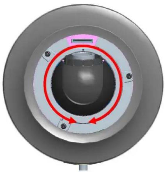
| Pan Range | 344° |
| Power Supply | Power over Ethernet (PoE) IEEE 802.3af/at |
| Connectors | RJ-45 Ethernet, I/O terminal block (DI/DO, audio input) |
| LED Indicators | Network (blue), Power (red/blue/purple) |
| Reset Button | Reboot (press briefly) or factory reset (hold 10 seconds) |
| Mounting | Wall or ceiling mount with included screws and anchors |
| Lens Adjustment | Manual pan/tilt; do not rotate more than 360° |
| Software Included | IP Installer, IP Surveillance Software |
| Package Contents | Camera, quick installation guide, software CD, accessories, drill template |
| Dimensions | Compact dome design (exact measurements not provided) |
| Weight | Not specified |
| Maintenance | Clean lens with soft dry cloth; avoid liquids |
| Safety Precautions | Do not rotate lens beyond 360°; use proper PoE switch |
| Spare Parts | Contact Intellinet support for replacement parts |
| General Information | Intellinet Network Solutions; www.intellinet-network.com |
Frequently Asked Questions - IDC-862 Intellinet
User questions about IDC-862 Intellinet
0 question about this device. Answer the ones you know or ask your own.
Ask a new question about this device
Download the instructions for your Security Camera in PDF format for free! Find your manual IDC-862 - Intellinet and take your electronic device back in hand. On this page are published all the documents necessary for the use of your device. IDC-862 by Intellinet.
USER MANUAL IDC-862 Intellinet
Network Mini Dome Camera
Hardware Installation Guide
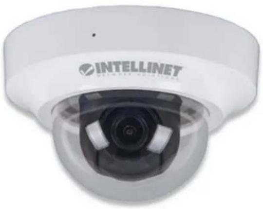
natural_image
Close-up of a white INTELLINET surveillance camera with lens and control panel (no visible text or symbols on body)Package Contents
| Dome Camera IDC-7571R | Outdoor Megapixel Night-Vision Network Dome Camera |
| Quick Installation Guide | Brief product information and quick installation |
| Software CD | IP Surveillance Software Intelligent IP InstallerUser ManualsLanguage Packs |
| Accessories 6 pin terminal | cable for DI/DO and audioScrew pack for wall and ceiling mounting (2 screws, 2 plastic wall anchors)Focus AdjustmentDrill Template |
Hardware Description


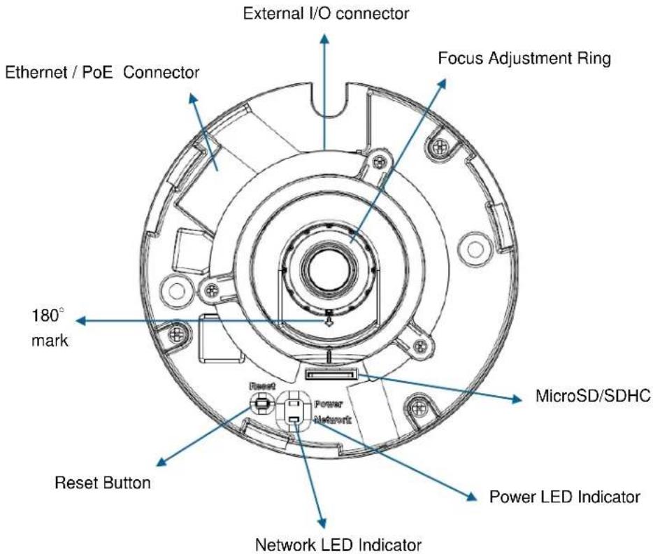
Factory Reset
Reset: With the camera turned on, press the reset button briefly to reboot the camera, or hold the reset button for 10 seconds to set all settings back to factory default values.
I / O Terminal Block
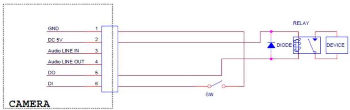
The Intellinet Network Camera provides an external I/O terminal block which is used to connect input / output devices such as alarms or sensors. The pin definitions are described below
| PIN | Definition Description Max. V/ A | |
| 1 | Ground | |
| 2 | + 5V DC | |
| 3 | AUDIO_In(+) | Unbalanced, 1.4Vp-p, 1Vrms, terminal block |
| 4 | AUDIO_In(+) | Unbalanced, 1.4Vp-p, 1Vrms, terminal block |
| 5 | Digital Output 1 | Uses an NPN transistor with the emitter connected to the GND pin. If used with an external relay, a diode must be connected in parallel with the load for protection against voltage transients. |
| 7 | Digital Input 1 | Connected to GND to activate, or leave floating (or unconnected) to deactivate. |

LED Indicators
| LED | Color | Indication |
| Network | Blue | Network activity is indicated by a flashing blue LED. |
| Power | Red Steady | red during booting up process |
| Blue Turns | blue upon completion of start-up | |
| Purple Flashing | during firmware upgrade | |
| Unlit Off when press reset button is pressed | ||
Hardware Installation
1) To open the camera housing use one hand to hold top cover and another hand to push against the bottom of the camera housing.
2) Shift top cover to left (counter-clockwise) to open the dome cover. The cover will not easily come off unless you apply a certain amount of force.
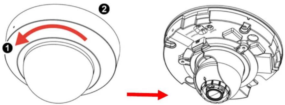
3) Attached the drill template to the wall. Drill three holes into the wall (two for screws and one for the connection cable if you want to route cables through conduit hole). Then push the supplied plastic anchors into the screw holes and secure the plate with supplied screws.
4) Align the three holes on the base of camera with the two plastic anchors on the wall or ceiling, insert the supplied screws to the corresponding hole and screw them.
5) Adjust the angle of camera to aim the shooting area.

natural_image
Technical line drawing of a mechanical assembly with three views (top, front, side), showing components like a cylindrical component and a circular component with alignment lines (no text or symbols)Lens Adjustment


WARNING:
DO NOT rotate the lens more than 360 degrees. Doing so will damage the camera lens module.
natural_image
Close-up of a mechanical component with concentric rings and red arrows indicating rotational direction (no text or symbols)Pan 344^
Cable Connections
Power over Ethernet (PoE)
Using a standard RJ-45 network cable, connect the dome camera to a IEEE802.3af/at compliant PoE switch or PoE injector.

flowchart
graph LR
    A["INTELLNET"] -->|1| B["Network Switch"]
    B --> C["Internet"]
RJ-45 Cable
Due to the very compact housing dimensions, using a network cable with a molded boot is not advisable. There is not enough room to connect the RJ45 connector to the socket without bending the cable, which will likely short the lifespan. We recommend using a network cable without a modeled strain relief boot.
Accessing the camera
Start the IP Installer application to set up the camera. More information can be found in the user manual on the installation CD.

INTELLINET NETWORK SOLUTIONS™ offers a complete line of active and passive networking products.
Ask your local computer dealer for more information or visit
www.intellinet-network.com
Copyright © INTELLINET NETWORK SOLUTIONS
All products mentioned are trademarks or registered trademarks of their respective owners.

Brand : Intellinet
Model : IDC-862
Category : Security Camera