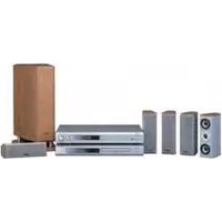
DHT-550SD - Home Theater DENON - Free user manual and instructions
Find the device manual for free DHT-550SD DENON in PDF.


| Product Type | Home Theater System |
| Brand | Denon |
| Model | DHT-550SD |
| Number of Channels | 5.1 |
| Power Output per Channel | 100 W (6 ohms, 1 kHz, 0.7% THD) |
| Amplifier Type | Discrete 5-channel power amplifier |
| Supported Audio Formats | Dolby Digital, DTS, Dolby Pro Logic II |
| Video Passthrough | 480i/576i, 480p/576p, 720p, 1080i, 1080p |
| HDMI Inputs | 2 |
| HDMI Output | 1 |
| Digital Audio Inputs | 1 optical, 1 coaxial |
| Analog Audio Inputs | 2 stereo RCA |
| Speaker Impedance | 6 ohms |
| Surround Sound Modes | Movie, Music, Night |
| Remote Control | Included |
| Dimensions (Receiver, W x H x D) | 434 x 107 x 359 mm |
| Weight (Receiver) | 7.5 kg |
| Speaker Dimensions (Front, W x H x D) | 152 x 305 x 180 mm each |
| Speaker Weight (Front) | 3.2 kg each |
| Subwoofer Dimensions | 225 x 420 x 315 mm |
| Subwoofer Weight | 8.0 kg |
| Power Consumption | 300 W (standby: 0.3 W) |
| Power Supply | AC 120 V, 60 Hz (US model) |
| Cleaning | Wipe with dry soft cloth; do not use solvents |
Frequently Asked Questions - DHT-550SD DENON
User questions about DHT-550SD DENON
0 question about this device. Answer the ones you know or ask your own.
Ask a new question about this device
Download the instructions for your Home Theater in PDF format for free! Find your manual DHT-550SD - DENON and take your electronic device back in hand. On this page are published all the documents necessary for the use of your device. DHT-550SD by DENON.
USER MANUAL DHT-550SD DENON
natural_image
Line drawing of a desktop audio equipment setup including a front-mounted device, a remote control unit, and a speaker tower (no text or symbols)FOR ENGLISH READERS PAGE 2 - PAGE 46 FÜR DEUTSCHE LESER SEITE 47 - SEITE 90 POUR LES LECTURS FRANÇAIS PAGE 91 - PAGE 134 PER IL LETTORE ITALIANO PAGINA 135 - PAGINA 178 PARA LECTORES DE ESPAÑOL PAGINA 179 - PAGINA 222 VOOR NEDERLANDSTALIGE LEZERS PAGINA 223 - PAGINA 286 FOR SVENSKA LASARE SIDA 267 - SIDA 310

CAUTION
RISK OF ELECTRIC SHOCK
DO NOT OPEN

CAUTION: TO REDUCE THE RISK OF ELECTRIC SHOCK, DO NOT REMOVE COVER (OR BACK). NO USER SERVICEABLE PARTS INSIDE. REFER SERVICING TO QUALIFIED SERVICE PERSONNEL.

The lightning flash with arrowhead symbol, within an equilateral triangle, is intended to alert the user to the presence of uninsulated "dangerous voltage" within the product's enclosure that may be of sufficient magnitude to constitute a risk of electric shock to persons.

The exclamation point within an equilateral triangle is intended to alert the user to the presence of important operating and maintenance (servicing) instructions in the literature accompanying the appliance.
WARNING: TO REDUCE THE RISK OF FIRE OR ELECTRIC SHOCK, DO NOT EXPOSE THIS APPLIANCE TO RAIN OR MOISTURE.
• DECLARATION OF CONFORMITY
We declare under our sole responsibility that this product, to which this occasion relates, is in conformity with the following standards
EN60065, EN58013, EN55020. EN61000-3-2 and EN61000-3-3.
Following the provisions of 73/23/EEC, 89/336/EEC and 93/88/EEC Directive.
FN60065, FN55013, FN55020, FN81000-3.2 e FN81000 3.3.
Allow for sufficient host dispersion when installed on a park
appraisal of an enel rak, search geprasiest.
- Handle the power cord carefully
Hold the plug when unloading the cord.
- Keaa the sat tran from moashura, water, and dust
• Urain into application for fall, butter and daffn.

- Unplug the power cord when not using the set for long banana at time.

‘ Ifor sets with ventilation holes
• Do not construct the ventilation holes.
- Do not let foreign objects in the set
• Do not let insectodes, benzana, and turner core in contact with the act.
- Not an accessible or modify the set in any
- Recit de appraisal democraten of op and/or size facilities.
- The ventilation should not be impeded by covering the
ventilation openings with items, such as newspapers,
table-cloths, curtains, etc.
- No naked flame sources, such as lighted cordies, should be placed on the apparatus.
- Please be care the environmental aspects of battery
disposal.
• The apparatus shall not be exposed to dripping or sclashing for use.
- No objects filled with liquids, such as vases, shall be placed on the apparatus.
■We greatly appreciate your purchase of the AVR-550SD.
To be sure you take maximum advantage of all the features the AVR-550SD has to offer, read these instructions carefully and use the set properly. Be sure to keep this manual for future reference, should any questions or problems arise.
"SERIAL NO.
PLEASE RECORD UNIT SERIAL NUMBER ATTACHED TO THE REAR OF THE CABINET FOR FUTURE REFERENCE"
INTRODUCTION
Thank you for choosing the DENON AVR-550SD Digital Surround A/V receiver. This remarkable component has been engineered to provide superb surround sound listening with AV theater sources such as DVD, as well as providing outstanding high fidelity reproduction of your favorite music sources.
As this product is provided with an immense array of features, we recommend that before you begin hookup and operation that you review the contents of this manual before proceeding.
TABLE OF CONTENTS
| 1 | Before Using....3 |
| 2 | Cautions on Installation....3 |
| 3 | Cautions on Handling....3 |
| 4 | Features....4 |
| 5 | Part Names and Functions....4, 5 |
| 6 | Read this First....5 |
| 7 | Setting up the Speaker Systems....5 |
| 8 | Connections....6 - 10 |
| 9 | Using the Remote Control Unit....10 |
| 10 | Setting up the System....11 - 16 |
| 11 | Remote Control Unit....16 - 19 |
| 12 | Operation....19 ~ 22 |
| 13 | Surround....22 ~ 28 |
| 14 | DSP Surround Simulation....28 ~ 31 |
| 15 | Listening to the Radio....32 ~ 35 |
| 16 | Using the sleep timer....35 |
| 17 | Last Function Memory....36 |
| 18 | Initialization of the Microprocessor....36 |
| 19 | Using the SYS-550SD (IDHT-550SD only)...36 ~ 39 |
| 20 | Additional Information....40 ~ 44 |
| 21 | Troubleshooting....45 |
| 22 | Specifications....46 |
| List of Preset Codes....311 ~ 313 |
CONTENTS
Check that the following parts are included in addition to the main unit:
AVR-550SD
| 1 MAIN UNIT....1 | 2 Operating instructions....1 | 3 Service station list....1 |
| 4 Remote control unit (RC-964)....1 | 5 RBP/AA batteries....2 | 6 AM loop antenna....1 |
| 7 FM indoor antenna....1 | ||
| 6 | ||
 |  |  |
SYS-550SD
| 1 Satellite speaker system (SC-A3L) | 4 |
| 3 Active subwoofer (DSW-3L) | 1 |
| 5 Cord B (3 m) | 3 |
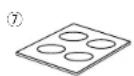
| 7 Anti-slip pad (4 pcs. / 1 sheet) | 5 |
| 2 Center speaker system (SC-C3L) | 1 |
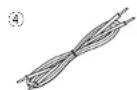
| 4 Cord A (10 m) | 2 |
| 6 Cord C (3 m, RCA PIN) | 1 |


1 BEFORE USING
Pay attention to the following before using this unit:
- Moving the set
To prevent short circuits or damaged wires in the connection cords, always unplug the power cord and disconnect the connection cords between all other audio components when moving the set.
- Before turning the power switch on
Check once again that all connections are proper and that there are not problems with the connection cords. Always set the power switch to the standby position before connecting and disconnecting connection cords.
- Store this instructions in a safe place.
After reading, store this instructions along with the warranty in a safe place. - Note that the illustrations in this instructions may differ from the actual set for explanation purposes.
2 CAUTIONS ON INSTALLATION
Noise or disturbance of the picture may be generated if this unit or any other electronic equipment using microprocessors is used near a tuner or TV.
If this happens, take the following steps:
• Install this unit as far as possible from the tuner or TV.
- Set the antenna wires from the tuner or TV away from this unit's power cord and input/output connection cords.
- Noise or disturbance tends to occur particularly when using indoor antennas or 300 Ω/ohms feeder wires. We recommend using outdoor antennas and 75 Ω/ohms coaxial cables.
For heat dispersal, leave at least 10 cm of space between the top, back and sides of this unit and the wall or other components.
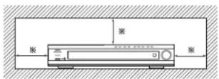


※10 cm or more
3 CAUTIONS ON HANDLING
- Switching the input function when input jacks are not connected
A clicking noise may be produced if the input function is switched when nothing is connected to the input jacks. If this happens, either turn down the MASTER VOLUME control or connect components to the input jacks.
- Muting of PRE OUT jacks, HEADPHONE jack and SPEAKER terminals
The PRE OUT jacks, HEADPHONE jack and SPEAKER terminals include a muting circuit. Because of this, the output signals are greatly reduced for several
seconds after the power switch is turned on or input function, surround mode or any other-set-up is changed. If the volume is turned up during this time, the output will be very high after the muting circuit stops functioning. Always wait until the muting circuit turns off before adjusting the volume.
- Whenever the power switch is in the STANDBY state, the apparatus is still connected on AC line voltage.
Please be sure to unplug the cord when you leave home for, say, a vacation.
ENGLISH
4 FEATURES
1. Dolby Virtual Speaker compatibility
The AVR-550SD is equipped with power amplifiers that make it compatible with new Dolby Virtual Speaker technology for recreating a 5.1-channel environment virtually using a 2-channel configuration. (Dolby Virtual Speaker is an proprietary technology of Dolby Laboratories.) A high performance digital signal processor enables playback of Dolby Digital and DTS multi-channel surround signals in the Dolby Virtual Speaker mode. Surround sound can be achieved with the Dolby Virtual Speaker mode for CDs and other 2-channel sources in combination with the Dolby Pro Logic II decoder.
2. Dolby Digital EX decoder system
Dolby Digital EX is a 6.1-channel surround format proposed by Dolby Laboratories that allows users to enjoy in their homes the "DOLBY DIGITAL SURROUND EX" audio format jointly developed by Dolby Laboratories and Lucas Films and first used for the movie "Star Wars Episode 1 - Phantom Menace".
The 6.1 channels of sound, including surround back channels, provide improved sound positioning and expression of space.
3. Dolby Pro Logic IIx compatibility
Dolby Pro Logic IIx furthers the matrix decoding technology of Dolby Pro Logic II to decode audio signals recorded on two channels into up to 7.1 playback channels, including the surround back channel. Dolby Pro Logic IIx also allows 5.1-channel sources to be played in up to 7.1 channels.
The mode can be selected according to the source. The Music mode is best suited for playing music, the Cinema mode for playing movies, and the Game mode for playing games. The Game mode can only be used with 2-channel audio sources.
4. Dolby Pro Logic II Game mode compatibility
In addition to the previously offered Music and Cinema modes, the AVR-550SD also offers a Game mode optimum for games.
5. DTS-ES Extended Surround and DTS Neo:6
The AVR-550SD is compatible with DTS-ES Extended Surround, a new multi-channel format developed by Digital Theater Systems Inc.
The AVR-550SD is also compatible with DTS Neo:6, a surround mode allowing 6.1-channel playback of regular stereo sources.
6. DTS 96/24 compatibility
The AVR-550SD can be decoded with sources recorded in DTS 96/24, a new multi-channel digital signal format developed by Digital Theater Systems Inc.
DTS 96/24 sources can be played in the multi-channel mode on the AVR-550SD with high sound quality of 96 kHz/24 bits or 88.2 kHz/24 bits.
7. On Screen Display
Troublesome operations such as adjusting the delay time and other parameters according to the listening environment are greatly simplified. The various parameters can be set simply by selecting the graphic displayed on the monitor screen according to the listening room's system environment.
8. Video Conversion Function
The AVR-550SD is equipped with a function for converting the signals input to the video input connector and S-Video input connector. With this function, the AVR-550SD's monitor out connector and the monitor (TV) can be connected with video pin-plug cords or an S-Video connection cord.
9. Dolby Digital
Using advanced digital processing algorithms, Dolby Digital provides up to 5.1 channels of wide-range, high fidelity surround sound. Dolby Digital is the default digital audio delivery system for North American DVD and DTV.
10.DTS (Digital Theater Systems)
DTS provides up to 5.1 channels of wide-range, high fidelity surround sound, from sources such as laser disc, DVD and specially-encoded music discs.
11. Component Video Switching
In addition to composite video and "S" video switching, the AVR-550SD provides 2 sets of component video (Y, PE/CE, PR/CR) inputs assignable, and one set of component video outputs to the television, for superior picture quality.
12. Auto Surround Mode
This function stores the surround mode last used for an input signal in the memory and automatically sets that surround mode the next time that signal is input.
5 PART NAMES AND FUNCTIONS
Front Panel
- For details on the functions of these parts, refer to the pages given in parentheses ( ).

1 Power operation switch .....(19)
② Headphones jack (PHONES) .....(21, 31)
3 SURROUND BACK indicator .....(23)
4 INPUT MODE indicator .....(19)
5 STANDBY indicator
6 Display
7 FUNCTION/SELECT knob .....(19, 20)
8 MASTER VOLUME control .....(20)
9 TUNING UP/DOWN buttons .....(32)
10 BAND button....(32)
11 TONE CONTROL button .....(21)
12 STATUS button....(22)
17 Power operation indicator .....(19)
18 Remote control sensor (REMOTE SENSOR)....(10)
Remote control unit
- For details on the functions of these parts, refer to the pages given in parentheses ( ).

6 READ THIS FIRST
This AV Surround Receiver must be setup before use. Following these steps.

flowchart
graph TD
    A["Step 1 (page 5 to 10)<br>Choose the best location to setup the speakers and connecting the components."] --> B["Step 2 (page 10)<br>Next, insert the batteries into the remote control unit."]
    B --> C["Step 3 (page 11 to 16)<br>Finally, setting up the system."]
7 SETTING UP THE SPEAKER SYSTEMS
■Speaker system layout
Basic system layout
- The following is an example of the basic layout for a system consisting of 7 speaker systems and a television monitor.
- For the layout when using two surround back speakers, see "Speaker Setting examples" (See page 41).

Front speaker systems
Set these at the sides of the TV or screen with their front surfaces as flush with the front of the screen as possible.
ENGLISH
8 CONNECTIONS
Connecting the audio components
- When making connections, also refer to the operating instructions of the other components. The power to these outlets is turned on and off when the power is switched between on and standby from the remote control unit or power switch.
- Do not plug in the AC cord until all connections have been completed.
- Be sure to connect the left and right channels properly (left with left, right with right).
- Insert the plugs securely. Incomplete connections will result in the generation of noise.
- Note that binding pin plug cords together with AC cords or placing them near a power transformer will result in generating hum or other noise
- Noise or humming may be generated if a connected audio equipment is used independently without turning the power of this unit on. If this happens, turn on the power of the this unit.

Connecting the DIGITAL jacks
Use these for connections to audio (video) equipment with digital output. Refer to page 14 for instructions on setting this terminal.
NOTES:
- Use 75 ohms cable pin cords for coaxial connections.
- Use optical cables for optical connections, removing the cap before connecting.
- The main unit's power must be turned on when recording the AVR 550SD.
NOTE:
If humming noise is generated by a tape deck, etc., move the tape deck away.
Connecting video components
- To connect the video signal, connect using a 75 Ω/ohms video signal cable cord. Using an improper cable can result in a drop in video quality.
- When making connections, also refer to the operating instructions of the other components.
• The AVR-550SD is equipped with a function for up-converting video signals.
• The signal connected to the video signal terminal is output to the S-Video monitor out terminals. - The REC OUT terminals have no conversion function, so when recording only connect the video terminals.

Connecting a video decks
• There are two sets of video deck (VCR) jacks, so two video decks can be connected for simultaneous recording or video copying
Video input/output connections:
- Connect the video deck's video output jack (VIDEO OUT) to the yellow VCR IN jack, and the video deck's video input jack (VIDEO IN) to the yellow VCR OUT jack using 75 Q/chms video coaxial pin plug cords.
Connecting the audio output jacks
- Connect the video deck's audio output jacks (AUDIO OUT) to the AUDIO jacks, and the video deck's audio input jacks (AUDIO INI to the PABIO Jacks using pin plug cords.
Connecting a video component equipped with S-Video jacks
- When making connections, also refer to the operating instructions of the other components.
- A note on the S input jacks
The input selectors for the S inputs and pin jack inputs work in conjunction with each other.
• The AVR-550SD is equipped with a function for converting video signals. - The signal connected to the S-Video signal terminal is output to the composite video monitor out terminals.
- The REC OUT terminals have no conversion function, so when recording only connect the S-Video terminals.

flowchart
graph TD
    A["Connecting a DVD player or video disc player (VDP)"]
    B["Connecting a TV/DBS tuner"]
    C["Connect the TV's or DBS tuner's S-video output jack IS-VIDEO OUTPUT to the I'VDDIIN jack using an S-jack connection cord."]
    D["Connecting a monitor TV"]
    E["Connecting a monitor TV MONITOR OUT"]
    F["Connecting the video decks"]
    G["Connect the video deck's S output jack IS-OUT to the S-VCO VCR IV jack and the video deck's S input jack IS-NI to the VCO VCR I jack Using S-jack connection cords."]
    H["Connecting the video decks"]
    I["Connect the components' audio inputs and outputs as described on page 6."]
- When connecting the AVR-550SD with a monitor TV or DVD player equipped with an SCART connector, use a converter cable (sold separately) as shown in the diagram.
* The AVR-550SD does not support input/output of RGB video signals.

ENGLISH
Connecting a Video Component Equipped with Color Difference (Component Y, PR/CR, PB/CB) Video Jacks (DVD Player)
- When making connections, also refer to the operating instructions of the other components.
- The signals input to the color difference (component) video jacks are not output from the VIDEO output jack (yellow) or the S-Video output jack. In addition, the video signals input to the VIDEO input (yellow) and S-Video input jacks are not output to the color difference (component) video jacks.
- Some video sources with component video outputs are labeled Y, CE, CR, or Y, Pb, Pr, or Y, R-Y, B-Y. These terms all refer to component video color difference output.
- At SYSTEM SETUP, the component video input terminal can be assigned for the input sources to which you want to connect AV devices. (For details, see page 15.)

• Video Conversion signals
| Signal input to the AVN-550SD | Monitor Output jacks | ||
| video signal output to VIDEO MONITOR OUT jack (yellow) | video signal output to 5-Video MONITOR OUT jack | video signal output to color difference (component) Video MONITOR OUT jack | |
| Video signal input jack | ○ | ○(Up-conversion) | × |
| 5 Video signal input jack | ○(Down-conversion) | ○ | × |
| Color difference (component) Video signal input jack | × | × | ○ |
- The color difference input jacks may be indicated differently on some TVs, monitors or video components ("Ch, CD and Y", "R-Y, B-Y and Y", "Fr, Pb and Y", etc.). For details, carefully read the operating instructions included with the TV or other component.
IO: Video signal output, ×: Video signal not output
Connecting the antenna terminals
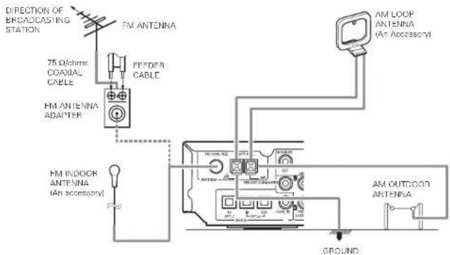
AM loop antenna assembly
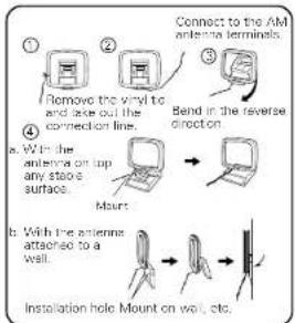
flowchart
graph TD
    A["Remove the vinyl to and raise out the connection line"] --> B["Bend in the reverse direction"]
    B --> C["Mount"]
    C --> D["Installation hole Mount on wall, etc."]
Connection of AM antennas
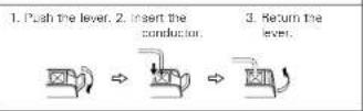
NOTES:
- Do not connect two FM antennas simultaneously.
- Even if an external AM antenna is used, do not disconnect the AM loop antenna.
- Make sure AM loop antenna lead terminals do not touch metal parts of the panel.
ENGLISH
Connecting the external input (EXT. IN) jacks
- These jacks are for inputting multi-channel audio signals from an outboard decoder, or a component with a different type of multi-channel decoder, such as a DVD Audio player, or a multi-channel SACD player, or other future multi-channel sound format decoder.
- When making connections, also refer to the operating instructions of the other components.

■ For instructions on playback using the external input (EXT, IN) jacks, see page 20.
Speaker system connections
- Connect the speaker terminals with the speakers making sure that like polarities are matched (③ with ⑥, ⑦ with ⑧). Mismatching of polarities will result in weak central sound, unclear orientation of the various instruments, and the sense of direction of the stereo being impaired.
- When making connections, take care that none of the individual conductors of the speaker cord come in contact with adjacent terminals, with other speaker cord conductors, or with the rear panel.
Speaker Impedance
- Speakers with an impedance of 6 to 16 Ω/ohms can be connected for use as speakers.
- The protector circuit may be activated if the set is played for long periods of time at high volumes when speakers with an impedance lower than the specified impedance are connected.
NOTE:
NEVER touch the speaker terminals when the power is on.
Doing so could result in electric shocks.
Connecting the speaker cords
- Loosen by turning counterclockwise.
- Insert the cord. 3. Tighten by turning cockwise.
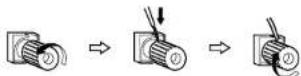
Protector circuit
- This unit is equipped with a high-speed protection circuit. The purpose of this circuit is to protect the speakers under circumstances such as when the output of the power amplifier is inadvertently short-circuited and a large current flow, when the temperature surrounding the unit becomes unusually high, or when the unit is used at high output over a long period which results in an extreme temperature rise. When the protection circuit is activated, the speaker output is out off and the STANDBY indicator LED flashes. Should this occur, please follow these steps: be sure to switch off the power of this unit, check whether there are any faults with the wiring of the speaker cables or input cables, and wait for the unit to cool down if it is very hot. Improve the ventilation condition around the unit and switch the power back on. If the protection circuit is activated again even though there are no problems with the wiring or the ventilation around the unit, switch off the power and contact a DENON service center.
Note on speaker impedance
- The protector circuit may be activated if the set is played for long periods of time at high volumes when speakers with an impedance lower than the specified impedance (for example, speakers with an impedance of lower than 4 Ω/ohrinst) are connected. If the protector circuit is activated, the speaker output is cut off. Turn off the set's power, wait for the set to cool down, improve the ventilation around the set, then turn the power back on.
ENGLISH
Connections
- When making connections, also refer to the operating instructions of the other components.
Connection jack for subwoofer with built-in amplifier (super woofer), etc. DSW-3L (DHT-550SD only) or commercially available speaker.

- Precautions when connecting speakers
If a speaker is placed near a TV or video monitor, the colors on the screen may be disturbed by the speaker's magnetism. If this should happen, move the speaker away to a position where it does not have this effect.
9 USING THE REMOTE CONTROL UNIT
Following the procedure outlined below, insert the batteries before using the remote control unit.
Range of operation of the remote control unit
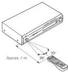
Point the remote control unit at the remote control sensor as shown on the diagram at the left.
NOTES:
- The remote control unit can be used from a straight distance of approximately 7 meters, but this distance will shorten or operation will become difficult if there are obstacles between the remote control unit and the remote control sensor, if the remote control sensor is exposed to direct sunlight or other strong light, or if operated from an angle.
- Noon signs or other devices omitting pulse-type noise nearby may result in malfunction, so keep the set as far away from such devices as possible.
Inserting the batteries
①Press as shown by the arrow and slide off.
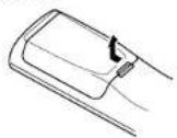
②Insert the R6P/AA batteries properly, as shown on the diagram.

③Close the lid

NOTES:
- Use only R6P/AA batteries for replacement.
- Be sure the polarities are correct. (See the illustration inside the battery compartment.)
- Remove the batteries if the remote control transmitter will not be used for an extended period of time.
- If batteries leak, dispose of them immediately. Avoid touching the leaked material or letting it come in contact with clothing, etc. Clean the battery compartment thoroughly before installing new batteries.
- Have replacement batteries on hand so that the old batteries can be replaced as quickly as possible when the time comes.
- Even if less than a year has passed, replace the batteries with new ones if the set does not operate even when the remote control unit is operated nearby the set. (The included battery is only for verifying operation. Replace it with a new battery as soon as possible.)
10 SETTING UP THE SYSTEM
- Once all connections with other AV components have been completed as described in "CONNECTIONS" (see pages 6 to 10), make the various settings described below on the display.
These settings are required to set up the listening room's AV system centered around the this unit.
• Use the following buttons to set up the system:
1 Set the slide switch to "AUDIO".

2 Use the following buttons to set up the system:
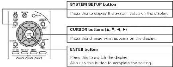
- System setup items and default values (set upon shipment from the factory)
| System setup Default settings | ||||||||||
| SpeakerConfiguration | Input the combination of speakers in your system and their corresponding sizes ISMALL for regular speakers, LARGE for full-size, full range) to automatically set the composition of the signe's output from the speakers and the frequency response. | Front So. | Center So. | Surround So. | Surround Back So. | Subwoofer | ||||
| Small | Small Small None | Yes | ||||||||
| Subwoofer mode | This selects the subwoofer speaker for playing deep bass signals. | LFE INormall | ||||||||
| Crossover Frequency | Set the frequency (Hz) below which the bass sound of the various speakers is to be output from the subwoofer. | 150 Hz | ||||||||
| Delay Time | This parameter is for optimizing the timing with which the audio signals are produced from the speakers and subwoofer according to the listening position. | Front L | Front R | Center | Subwoofer | Surround L | Surround R | Surround Back | ||
| 3.6 m | 3.6 m | 3.6 m | 3.6 m | 3.0 m | 3.0 m | None | ||||
| Channel Level | This adjusts the volume of the signals output from the speakers and subwoofer for the different channels in order to obtain opimum effects. | Front L | Front R | Center | Subwoofer | Surround L | Surround R | Surround Back | ||
| 0 dB | 0 dB | 0 dB | 0 dB | 0 dB | None | |||||
| Digital In Assignment | This assigns the digits input jacks for the different input sources. | Input source | VCH DVD/WDP | TW/DBS | - | - | ||||
| Digital Inputs | COAXIAL | -OPTICAL 2GPTICA | ||||||||
| Video In Assignment | This assigns the component video input jacks for the different video input sources. | Input source | DVD/WDP | TW/DBS | - | - | - | |||
| Component Inputs | VDCO 1 V | DEO 2 | - | - | - | |||||
| System setup Default settings | ||
| Auto Surround Mode | Auto surround mode function setting. Auto Surround Mode = ON | |
| Ext. In SW Level | Set the Ext. In Subwoofer channel playback level. | Ext. In SW level = +13 dB |
| On Screen Display | This sets whether or not to display the on-screen display that appears on the monitor screen when the controls on the remote control unit or main unit are operated. | ON |
NOTES:
- The AVR-550SD's on-screen display function is designed for use with high resolution monitor TVs, so it may be difficult to read small characters on TVs with small screens or low resolutions.
• The setup menu is not displayed when headphones are being used.
Before setting up the system
1 Check that all the components are correct, then press the POWER operation switch on the main unit to turn on the power.
(Kain unit)
2 Press the SYSTEM SETUP button to enter the setting.

NOTE: Please make sure the "AUDIO" position of the slide switch on the remote control unit.
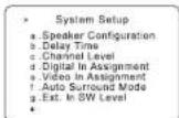
3 Press the (CAN) and ENTER button to switch to the SPEAKER CONFIGURATION SET UP.

NOTE:
- Press the SYSTEM SETUP button again to finish system set up. System set up can be finished at any time. The changes to the settings made up to that point are entered.
ENGLISH
ENGLISH
Setting the type of speakers
- Set up in function of your speaker systems. Performing this setup optimizes the system.
• The composition of the signals output to the different channels and the frequency response are adjusted automatically according to the combination of speakers actually being used.
1

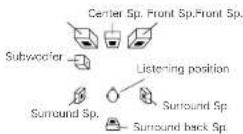
Set whether or not speakers are connected and, if so, their size parameters.
- To select the speaker

• To select the parameter
1 FRNT Small
2

Press the (down) button to enter the settings and switch to the SUBWOOFER MODE setting.
- Parameters
Large..... Select this when using speakers that can fully reproduce low sounds of below 80 Hz.
Small..... Select this when using speakers that cannot reproduce low sounds of below 80 Hz with sufficient volume. When this setting is selected, low frequencies of below 80 Hz are assigned to the subwoofer. (Example: SC-A3L, SC-C3L)
None..... Select this when no speakers are installed.
Yes/No.... Select "Yes" when a subwoofer is installed, "No" when it's not installed.
- About the surround back speaker
When "S.Back. Sp." is selected, the speaker systems change as described below.
When "NONE" is selected 5.1cn speaker system
When "Large" or "Small" is selected and "1Speaker" is selected ....6.1ch speaker system The surround back audio signals are output from both the speaker terminals and the PRE OUT connector's left channel. Connect one of these. A separate, commercially available pre-main (power) amplifier is needed to connect the PRE OUT connector.
When "2 speaker" is selected 7.1ch speaker system
The surround back audio signals are only output from the PRE OUT connector. Connect a commercially available pre-main (power) amplifier to output the audio signals. No sound is output from the "Surr. Back" speaker terminals.
NOTE:
Select "Large" or "Small" not according to the physical size of the speaker, but according to the bass reproduction capacity at 80 Hz. If you cannot determine the best setting, try comparing the sound when set to "Small" and when set to "Large", at a level that will not damage the speakers.
Caution:
In case the subwoofer is not used, be sure to set "Subwoofer = No", or the bass sound of front channel is divided to subwoofer channel and not reproduced in some mode.
If the subwoofer has sufficient low frequency playback capacity, good sound can be achieved even when "Small" is set for the front, center and surround speakers.
For the majority of speaker system configurations, using the Small setting for all five main speakers and Subwoofer. On with a connected subwoofer will yield the best results.
Setting the Subwoofer mode and Crossover Frequency
This screen is not displayed when not using a subwoofer.
- Set the crossover frequency and subwoofer mode according to the speaker system being used.
- When using in combination with the SYS-550SD, we recommend turning the DSW-3L's LF DIRECT switch on and setting the AVR-550SD's crossover frequency to 150 Hz. (See page 37.)
1
the "Subwoofer
Select the setting.


2
Select the "Crossover Frequency" mode.
Select the frequency.



3

Press the ENTER button to enter the setting and switch to the DELAY TIME setting.
NOTES:
— Assignment of low frequency signal range —
- The signals produced from the subwoofer channel are LFE signals (during playback of Dolby Digital or DTS signals) and the low frequency signal range of channels set to "SMALL" in the setup. The low frequency signal range of channels set to "LARGE" are produced from those channels.
— Crossover Frequency —
- When "Subwoofer" is set to "Yes" at the "Speaker Configuration Setting", set the frequency (Hz) below which the bass sound of the various speakers is to be output from the subwoofer (the crossover frequency).
- For speakers set to "Small", sound with a frequency below the crossover frequency is cut, and the cut bass sound is output from the subwoofer instead.
NOTE: For ordinary speaker systems, we recommend setting the crossover frequency to 80 Hz. When using small speakers, however, setting the crossover frequency to a high frequency may improve frequency response for frequencies near the crossover frequency.
— Subwoofer mode —
- The subwoofer mode setting is only valid when "Large" is set for the front speakers and "YES" is set for the subwoofer in the "Speaker Configuration" settings (see page 12).
- When the "LFE+MAIN" playback mode is selected, the low frequency signal range of channels set to "Large" are produced simultaneously from those channels and the subwoofer channel. In this playback mode, the low frequency range expand more uniformly through the room, but depending on the size and shape of the room, interference may result in a decrease of the actual volume of the low frequency range.
- Selection of the "LFE" play mode will play the low frequency signal range of the channel selected with "Large" from that channel only. Therefore, the low frequency signal range that are played from the subwoofer channel are only the low frequency signal range of LFE (only during Dolby Digital or DTS signal playback) and the channel specified as "Small" in the setup menu.
- Select the play mode that provides bass reproduction with quantity.
- When the subwoofer is set to "Yes", bass sound is output from the subwoofer regardless of the subwoofer mode setting in surround modes other than Dolby/DTS.
- In surround modes other than Dolby Digital and DTS, if the subwoofer is set to "YES", the low frequency portion is always output to the subwoofer channel. For details, refer to "Surround Modes and Parameters" on page 30.
Setting the delay time
- Input the distance between the listening position and the different speakers to set the delay time for the surround mode.
Preparations:
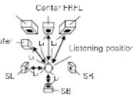
Measure the distances between the listening position and the speakers
(L1 to L5 on the diagram at the right).
L1: Distance between center speaker and listening position
L2: Distance between front speakers and listening position
L3: Distance between surround speakers and listening position
L4: Distance between surround back speaker and listening position
L5: Distance between subwoofer and listening position
CAUTION:
* Please note that the difference for every speaker should be 6 m or less.
NOTE:
- No setting when "None" has been selected for the Speaker Configuration setting.
1

Select the speaker to be set.


7.1ch Speaker System6.1ch Speaker
2

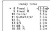
Set the distance between the speaker and listening position.
The distance changes in units of 0.1 meters each time the button is pressed. Select the value closest to the measured distance.
3

Press the ENTER button to enter the setting and switch the CHANNEL LEVEL setting.
ENGLISH
Setting the channel level
- Use this setting to adjust to that the playback level between the different channel is equal.
- From the listening position, listen to the test tones produced from the speakers to adjust the level.
- The level can also be adjusted directly from the remote control unit. (For details, see page 23.)
- When connecting a commercially available pre-main amplifier to the surround backup pre-out connectors and using a surround backup speaker, the level changes when the pre-main amplifier's volume control is adjusted, so adjust the volume with the pre-main amplifier's volume control in function of this setting.
1


Set the mode.
Select "Auto" or "Manual".

16 Channel Level
Test Tone [Auto] Manual Test Tone Start Yes Level Clear Yes
• Auto
Adjust the level while listening to the test tones
produced automatically from the different speakers.
- Manual
Select the speaker from which you want to produce the test tone to adjust the level.
2


Press the 📋 (down) button and select "Yes" to start Test Tone.
T. TONE STKYES
16 Channel Level
Test Tone [Auto>Manual]
Test Tone Start Yes<
Level Clear Yes<
3


a. If the "Auto" mode is selected:
Test tones are automatically emitted from the different speakers.
The test tones are emitted from the different speakers in the following order, at 4-second intervals the first time and second time around, 2-second intervals the third time around and on:

Use the CURSOR left and right buttons to adjust all the speakers to the same volume.
The volume can be adjusted between -12 dB and -12 dB in units of 1 dB.
b. When the "Manual" mode is selected.
Use the CURSOR up and down to select the speaker for which you want to output test tones, then use the CURSOR left and right to adjust so that the volume of the test tones from the various speakers is the same.

Examples
When the volume is set to -12 dB while the Front Lch speaker is selected
4

Press the ENTER button to enter the setting and switch the DIGITAL INPUT setting.
NOTES:
- When you adjust the channel level's while in the TEST TONE mode, the channel level adjustments made will affect all surround modes. Consider this mode a Master Channel Level adjustment mode.
- You can adjust the channel level's for each of the following surround modes: DIRECT, STEREO, DOLBY/DTS SURROUND, 5/8 CH STEREO, MONO MOVIE, ROCK ARENA, JAZZ CLUB, VIDEO GAME, MATRIX and DOLBY VIRTUAL SPEAKER.
Setting the Digital In Assignment
- This setting assigns the digital input jacks of the AVR-550SD for the different input sources.
1

Select the digital input jack to be assigned to the input source.
• To select the digital input jack
17 CORX VCR
Digital In Assignment
17 COAXIAL : < VCR > 18 OPTICAL1 : DVD/VDP 19 OPTICAL2 : TV/DBS
2

- To select the input source Select "OFF" if nothing is connected.
3

Press the ENTER button to enter the setting and switch the COMPONENT VIDEO INPUT setting.
NOTE:
• TUNER cannot be selected.
Setting the Video In Assignment
- This setting assigns the color difference (component) video input jacks of the AVR-550SD for the different input sources.
1

Select the component (Y, Pb/Cs and Pn/Cn) video input terminal to be assigned to the input source.
- Component video terminal selection
20 VIN1 D DU

2

- Input source selection Select "OFF" if nothing is connected.
3

Press the ENTER button to enter the setting and switch the AUTO SURROUND MODE setting.
Setting the Auto Surround Mode
For the three kinds of input signals as shown below, the surround mode played the last is stored in the memory. At next time it the same signal inputs, the memorized surround mode is automatically selected and the signal is played. Note that the surround mode setting is also stored separately for the different input function.
| SIGNAL Default Auto Surround Mode | ||
| 1 | Dialog and PCM 2-channel signals STEREO | |
| 2 | channel signals of Dolby Digital, DTS or other multichannel format Dolby PI | II Cinema |
| 3 | Multichannel signals of Dolby Digital, DTS or other multichannel format | Dolby or DTS Surround |
1

Select "ON" if you want to use the auto surround mode, "OFF" if you do not want to use it.
22 ATSURR.O N
22 Auto Surround Mode
ON > OFF
2

Press the ENTER button to switch the EXT. IN SW LEVEL setting.
Setting the Ext. In SW Level
- Set the playback level of the analog input signal connected to the Ext. In terminal
1
Select desired setting
- Select according to the specifications of the player being used.
Also refer to the player's operating instructions.
+15dB (default) recommended. 10, +5, 10 and +15 can be selected.)
23 EXIN SW+ 51
23 Ext. in SW Level
Subwoofer Level
<+15d回
2

Press the ENTER button to switch the ON SCREEN DISPLAY setting.
Setting the On Screen Display (OSD)
- Use this to turn the on-screen display (messages other than the menu screens) on or off.
1

Select "ON" or "OFF".

24 On Screen Display
ON>OFF
2

Press the ENTER button to switch the AUTO PRESET MEMORY setting.
ENGLISH
Auto Tuner Presets
- Use this to automatically search for FM broadcasts and store up to 40 stations at preset channels A1 to B, B1 to B, C1 to B, D1 to B and E1 to B.
NOTE:
- If an FM station cannot be preset automatically due to poor reception, use the "Manual tuning" operation to tune in the station, then preset it using the manual "Preset memory" operation.
1

Use the CURSOR button to select "Yes", "Search" flashes on the screen and searching begins. "Completed" appears once searching is completed. The display automatically switches to screen.
25 PRESET<YES
25 Auto Preset Memory Auto Tuning And Preset Station Memory Storing Preset Memory Start Yes
* See page 35 for instructions on setting the sleep timer.
After setting up the system
1

Press the SYSTEM SETUP button to finish system set up.
This completes the system setup operations. Once the system is set up, there is no need to make the settings again unless other components or speakers are connected to or the speaker layout is changed.
- On-screen display signals
| Signals input to the AVR-560SD | On-screen display signal output | |||
| VIDEO signal input jack (yellow) | 5-video signal input jack | Video signal output to VIDEO MONITOR OUT jack (yellow) | Video signal output to 5 Video MONITOR OUT jack. | |
| 1 | × | × | ○ | ○ |
| 2 | ○ | × | ○ | ○ |
| 3 | × | ○ | ○ | ○ |
| 4 | ○ | ○ | × | ○ |
10: Signal
x: No signal
(2) On-screen signals output
X: On-screen signals not output

REMOTE CONTROL UNIT
Operating DENON audio components
- Turn on the power of the different components before operating them.
1
Set mode switch 1 to "AUDIO".

2
Set mode switch 2 to the position for the component to be operated. (CD, CDR/MD or Tape deck)


3
Operate the audio component.
- For details, refer to the component's operating instructions.
※ While this remote control is compatible with a wide range of infrared controlled components, some models of components may not be operated with this remote control.
- CD player (CD) and CD recorder and MD 2. Tape deck (TAPE) system buttons recorder (CDR/MD) system buttons

◀◀, ▶▶: Manual search (forward and reverse)
■: Stop ▶: Play
◀◀, ▶▶: Auto search (cue) ■: Pause
DISC SKIP = Switch disos (for CD changers only)
- Tuner system buttons
| SAMSUNG | |||
| SAMSUNG | |||
| SAMSUNG | |||
| 1 | 2 | 3 | + |
| 4 | 5 | 6 | - |
| 7 | 8 | 9 | + |
| 0 | -10 | - | |
| SET | UNKNOWN | RANGE | LOAD |

◀◀: Rewind
▶▶: Fast-forward
■: Stop
▶: Forward play
◀ Reverse play
A/B:Switch between decks A and B
SHIFT: Switch preset channel range
CHANNEL +, - : Preset channel up/down
TUNING +, -: Frequency up/down
BAND : Switch between the AM and FM bands
MODE : Switch between auto and mono
MEMORY : Praset memory
NOTE:
- TUNER can be operated when the switch is at "AUDIO" position.
Preset memory
DENON and other makes of components can be operated by setting the preset memory.
This remote control unit can be used to operate components of other manufacturers without using the learning function by registering the manufacturer of the component as shown on the List of Preset Codes (pages 311-313).
Operation is not possible for some models.
1
Set mode switch 1 to "AUDIO" or "VIDEO".

Set the AUDIO side for the CD, Tape deck or CDR/MD position, to the VIDEO side for the DVD/VDP, DBS/CABLE, VCR or TV position.
2
Set mode switch 2 to the component to be registered.

3
Press the ON/SOURCE button and the OFF button at the same time.

- Indicator flash.

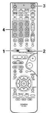
4

Referring to the included List of Preset Codes, use the number buttons to input the preset code is 3-digit number for the manufacturer of the component whose signals you want to store in the memory.
5
To store the codes of another component in the memory, repeat steps 1 to 4.
NOTES:
- The signals for the pressed buttons are emitted while setting the preset memory. To avoid accidental operation, cover the remote control unit's transmitting window while setting the preset memory.
- Depending on the model and year of manufacture, this function cannot be used for some models, even if they are of makes listed on the included list of preset codes.
- Some manufacturers use more than one type of remote control code. Refer to the included list of preset codes to change the number and check.
- The preset memory can be set for one component only among the following: CDR/MD, DVD/VDP and DBS/CABLE.
The preset codes are as follows upon shipment from the factory and after resetting:
TV, VCR......HITACHI
CD. TAPE DENON
CDR/MD DENON (CDR)
DVD/DP DENON (DVD)
DBS/CABLE ABC ICABLE
DESIGNED BY: 102-534
Operating component stored in the preset memory
1
Set mode switch 1 to "AUDIO" or "VIDEO".

Set the AUDIO side for the CD, tape deck or CDR/MD position, to the VIDEO side for the DVD/VDP, DBS/CABLE, VCR or TV position.
2
Set mode switch 2 to the component you want to operate.


3
Operate the component.
- For details, refer to the component's operating instructions. - Some models cannot be operated with this remote control unit.
1.
Digital video disc player (DVD) system buttons
- Video disc player (VDP) system buttons
POWER : Power on/standby (ON/SOURCE)




POWER : Power on/standby (ON/SOURCE)
◀◀, ▶▶: Manual search (forward and reverse)
■: Stop
▶: Play
▶▶. ▶▶: Auto search (cue)
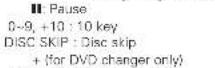
II: Pause
0\~9, +10:10 key
NOTE:
- Some manufacturers use different names for the DVD remote control buttons, so also refer to the instructions on remote control for that component.
ENGLISH
3. Video deck (VCR) system buttons
POWER : Power on/standby
ION/SOURCE
◀◀, ▶▶:
Manual search
广力云智慧零售收银系统
(forward and reversal
■: Stcd
▶: P
- 174
II. Pause
Channel: Channels
+

4. Digital broadcast satellite (DBS) tuner and cable (CABLE) system buttons
POWER: Power on/standby
(ON/SOURCE)
MENU : Menu
RETURN : Return
A. ▼, ▲, ▶: Cursor up, down, left
and right
ENTER: Enter
CHANNEL:Switch channels
+,-
0\~9, +10: Channels
DISPLAY: Switch display
VOL +, -: Volume up/down

5. Monitor TV (TV) system buttons
POWER: Power on/standby
ION/SOURCE
MENU:Menu
RETURN: Return
△. ▽. <. >: Cursor up, down, left
and right
ENTER : Enter
CHANNEL: Switch channels
+ -
0-9,+10:Channels
DISPLAY: Switch display
TVVCH : Switch between TV
and video player
TV VOL : Volume up/down
+,-

natural_image
Front view of a remote control with keypad and buttons (no readable text or symbols)Punch Through
- "Punch Through" is a function allowing you to operate the PLAY, STOP, MANUAL SEARCH and AUTO SEARCH buttons on the CD, TAPE, CDR/MD, DVD/VDP or VCR components when in the DES/CABLE or TV mode. By default, nothing is set.
1
Set mode switch 1 to "VIDEO".

2
Set mode switch 2 to the component to be registered (DBS/CABLE or TV).

3
Press the DVD/VDP POWER button and the TV POWER button at the same time.

- Indicator flash

4

Input the number of the
component you want to
set. (See Table 1)
Table 1
| No. | |
| CD | 1 |
| TAPE | 2 |
| CDR/MD | 3 |
| DVD/VDP | 4 |
| VCR | 5 |
| No setting | 0 |
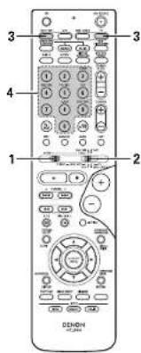
NOTES:
- For this CD, CDR, MD and TAPE components, buttons can be operated in the same way as for Denon audio components (page 16).
- The TV can be operated when the switch is at DVD/VDP, VCR, TV position
12 OPERATION
Before operating
1 Refer to "CONNECTIONS" (pages 6 to 10) and check that all connections are correct.
2 Set the remote control unit's slide switch to the AUDIO position. (only when operating with the remote control unit)

3 Tum on the power. Press the power operation switch (button).


|Main unit| (Remote control unit)
When pressed, the power turns on and the display lights. The sound is muted for several seconds, after which the unit operates normally.
When pressed again, the power turns off, the standby mode is set and the display turns off. Whenever the ON/STANDBY button is in the STANDBY state, the apparatus is still connected on AC line voltage. Please be sure to unplug the cord when you leave home for, say, a vacation.
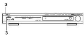

Playing the input source

1 Select the input source to be played. Example: DVD


(Main unit) (Remote control unit)
2 Select the input mode.
- Selecting the analog mode
Press the ANALOG button to switch to the analog input.

Remote control unit
- Selecting the external input (EXT. IN) mode Press the EXT. IN to switch the external input

(Remate control unit)
- Selecting the AUTO, PCM and DTS modes The mode switches as shown below each time the INPUT MODE button is pressed.

|Remote control unit

Input mode selection function
Different input modes can be selected for the different input sources. The selected input modes for the separate input sources are stored in the memory. ① AUTO (auto mode)
In this mode, the types of signals being input to the digital and analog input jacks for the selected input source are detected and the program in the AVR-550SD's surround decoder is selected automatically upon playback. This mode can be selected for all input sources other than TUNER.
The presence or absence of digital signals is detected, the signal input to the digital input jacks are identified and decoding and playback are performed automatically in DTS, Dolby Digital or PCM (2 channel stereo) format. If no digital signal is being input, the analog input jacks are selected.
Use this mode to play Dolby Digital signals.
② PCM (exclusive PCM signal playback mode)
Decoding and playback are only performed when PCM signals are being input.
Note that noise may be generated when using this mode to play signals other than PCM signals.
① DTS (exclusive DTS signal playback model)
Decoding and playback are only performed when DTS signals are being input.
④ ANALOG (exclusive analog audio signal playback mode)
The signals input to the analog input jacks are decoded and played.
⑤ EXT. IN (external decoder input jack selection mode) The signals being input to the external decoder input jacks are played without passing through the surround circuitry.
ENGLISH
NOTE:
- Note that noise will be output when CDs or LDs recorded in DTS format are played in the "PCM" exclusive PCM signal playback or "ANALOG" exclusive PCM signal playback mode. Select the AUTO or DTS mode when playing signals recorded in DTS.
Notes on playing a source encoded with DTS - Noise may be generated at the beginning of playback and while searching during DTS playback in the AUTO mode. If so, play in the DTS mode.
In some rare cases the noise may be generated when you preform the operation to stop playback of a DTS-CD or DTS-LD.
3
Select the play mode.
Press the SURROUND MODE button, then turn the SELECT knob.
Example: Stereo


[Main unit] (Remote control unit)
* To select the surround mode while adjusting the surround parameters, tone defeat or tone control, press the surround mode button then operate the selector.

(Main unit)
4
Start playback on the selected component.
- For operating instructions, refer to the component's manual.
5
Adjust the volume.

The volume level is displayed on the master volume level display.

(Main unit)

Remote control units
The volume can be adjusted within the range of -70 to 0 to 16 dB, in steps of 1 dB. However, when the channel level is set as described on page 23, if the volume for any channel is set at +1 dB or greater, the volume cannot be adjusted up to 18 dB. (In this case the maximum volume is adjusted to "18 dB — (Maximum value of channel level)".)
Input mode when playing DTS sources
- Noise will be output if DTS-compatible CDs or LDs are played in the "ANALOC" or "PCM" mode. When playing DTS-compatible sources, be sure to connect the source component to the digital input jacks (OPTICAL/COAXIAL) and set the input mode to "DTS".
Input mode display
• In the AUTO mode

One of these lights, depending on the input signal.
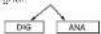
• In the DIGITAL PCM mode

DIG
• In the DIGITAL DTS mode

Dig
- In the ANALOG mode

ANA
Input signal display
• DOLBY DIGITAL
One of these lights, depending on the input signal

• DTS

• PCM

The lights when digital signals are being input properly. If the does not light, check whether the digital input component setup (page 14) and connections are correct and whether the component's power is turned on.
NOTE:
- The Indicator will light when playing CD-ROMs containing data other than audio signals, but no sound will be heard.
Playback using the external input (EXT. IN) jacks
1
Set the external input (EXT, IN) mode. Press the EXT, IN to switch the external input.

(Remole control unit)
Once this is selected, the input signals connected to the FL (front left), FR (front right), C (center), SL (surround left), and SR (surround right) channels of the EXT. IN jacks are output directly to the front left and right), center, surround (left and right) speaker systems without passing through the surround circuitry. In addition, the signal input to the SW (subwoofer) jack is output to the PRE OUT SUBWOCER jack.
2
Cancalling the external input mode To cancel the external input (EXT, INI setting, press the INPUT MODE (AUTO, PCM, DTS) or ANALOG button to switch to the desired input mode. (See page 19.)

Remote control unit
- When the input mode is set to the external input (EXT. IN), the play mode (IDIRECT, STEREO, DOLBY/DTS SURROUND, 5CH/6CH STEREO, VIRTUAL SURROUND (DOLBY VIRTUAL SPEAKER) or DSP SIMULATION) cannot be selected.

NOTES:
• In play modes other than the external input mode, the signals connected to C, SL, SR and SW jacks cannot be played. In addition, signal's cannot be output from channels not connected to the input jacks.
- The external input mode can be set for any input source. To watch video while listening to sound, select the input source to which the video signal is connected, then set this mode.
Playing audio sources
The AVR-550SD is equipped with two 2-channel playback modes exclusively for music. Select the mode to suit your tastes.
1
DIRECT mode
Use this mode to achieve good quality 2-channel sound while watching images. In this mode, the audio signals bypass such circuits as the tone circuit and are transmitted directly, resulting in good quality sound.

(Mar unit) (Remote control unit)

2
STEREO mode
Use this mode to adjust the tone and achieve the desired sound while watching images.

(Main units) (Remote control unit)

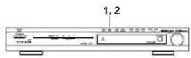

After starting playback
[1] Adjusting the sound quality (tone)
- The tone control function will not work in the direct mode.
1
The tone switches as follows each time the TONE CONTROL button is pressed.

(Main unit)
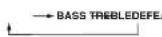
2
With the name of the volume to be adjusted selected, turn the SELECT knob to adjust the level.
- To increase the bass or treble: Turn the control clockwise. (The bass or treble sound can be increased to up to +6 dB in steps of 1 dB.)
- To decrease the bass or treble: Turn the control counterclockwise. (The bass or treble sound can be decreased to up to -6 dB in steps of 1 dB.)

[2] Listening over headphones
1
Plug the headphones' plug into the jack.
■ Connect the headphones to the PHONES jack.
The speaker output is automatically turned off when headphones are connected.
3
If you do not want the bass and treble to be adjusted, turn on the tone defeat mode.

Main unit
The signals do not pass through the bass and treble adjustment circuits, so it provides higher quality sound.
[3] Turning the sound off temporarily (MUTING)
1
Use this to turn off the audio output temporarily.
Press the MUTING button.
* Cancelling MUTING mode.
- Press the MUTING button again.
- Muting will also be cancelled when MASTER VOL is adjusted up or down.


(Remote control unit)
NOTE:
To prevent hearing loss, do not raise the volume level excessively when using headphones.

1

ENGLISH
[4] Combining the currently playing sound with the desired image
1
Simulcast playback Use this switch to monitor a video source other than the audio source. Press the VIDEO SELECT button repeatedly until the desired source appears on the display.

(Remote control unit)
* Cancelling simulcast playback.
- Select "SOURCE" using the VIDEO SELECT button.
- Switch the program source to the component connected to the video input jacks.

Display
IN=0 SOURCE
[5] Checking the currently playing program source, etc.
1
On screen display
- Each time an operation is performed, a description of that operation appears on the display connected to the unit's VIDEO MONITOR OUT jack. Also, the unit's operating checked during playback by remote control unit's ON SCR button.
Such information as the position of the input selector and the surround parameter settings is output in sequence.

(Remote control unit)
2
Status
- Also, the unit's operating status can be checked during playback by pressing the main unit's STATUS button. Such information as the position of the input selector and the surround parameter settings is output in sequence.
3
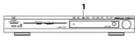
Using the dimmer function - Use this to change the brightness of the display. The display brightness ch in four steps (bright, med dim and off) by pressing t main unit's DIMMER butt repeatedly.

Main Unit


13
SURROUND
Before playing with the surround function
- Before playing with the surround function, be sure to use the test tones to adjust the playback level from the different speakers. This adjustment can be performed with the system setup (see page 11) or from the remote control unit, as described below.
- Adjusting with the remote control unit using the test tones is only possible in the "Auto" mode and only effective in the DOLEYIDTS SURROUND modes. The adjusted levels for the different modes are automatically stored in the memory.
1
Set the DOLBY/DTS SURROUND IDolby Pro Logic II or Dolby Digital or DTSI modes.


(Main unit) (Remote control unit)
2
Press the TEST TONE button.

(Remote control unit)
3
Test tones are output from the different speakers. Use the channel volume adjust buttons to adjust so that the volume of the test tones is the same for all the speakers.

(Remole control unit)
NOTE:
- Please make sure the "AUDIO" position of the slide switch on the remote control unit.
4
After completing the adjustment, press the TEST TONE button again.

(Remote control unit)

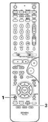
- After adjusting using the test tones, adjust the channel levels either according to the playback sources or to suit your tastes, as (described) below.
1
Select the speaker whose level you want to adjust.

(Hemote control unit)
The channel switches as shown below each time the button is pressed.

NOTE:
- Please make sure the "AUDIO" position of the slide switch on the remote control unit.
- If the channel levels are adjusted separately after adjusting the fader, the fader adjustment values are cleared, so adjust the fader again.
2
Adjust the level of the selected speaker.
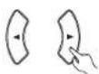
[Remote control unit]
* Default setting of channel level is 0 dB.
The level of the selected speaker can be adjusted within the range of +12 to -12 dB using the cursor buttons.
- SW channel level can be turned off by decreasing one step from -12 dB.
OFF -12 dB 12 dB

Dolby Digital mode (only with digital input) and DTS Surround (only with digital input)
1
Select the input source.
Playback with a digital input
①Select an input source set to digital (COAXIAL/OPTICAL) (see page 14).
Example: DVD


(Main unit) (Remote control unit)
② Set the input mode to "AUTO", "PCM" or "DTS".

(Remote control unit)
2
Select the Dolby/DTS Surround mode.


(Main unit) (Remote control unit)
When performing this operation from the main unit's panel, press the SURROUND MODE button, then turn the SELECT knob and select Dolby Pro Logic II or DTS NEO:6.


(Main unit) [Main unit]
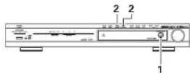

3
Play a program source with the


- Light
• The Dolby Digital indicator lights when playing Dolby Digital sources.
—— Light
- The DTS indicator lights when playing DTS sources.
AIR DETECT Light SURROUND
- The SIGNAL DETECT indicator lights when playing 6.1-channel surround sources containing the identification signal.
When the SIGNAL DETECT indicator is lit, we recommend turning the surround back channel using the SURROUND BACK button on the remote control unit during playback.
To use DTS 96/24 sources with the optimum system, we recommend turning the surround back channel off.
Operate the SURROUND BACK button to switch Surround Back CH ON/OFF.


(Hemote control unit)
- Lights when the SURROUND BACK button is on.
ENGLISH
4

(Remote control unit)
Display the surround parameter menu.
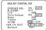

5

(Remote control unit)
Select the various parameters.
6

(Demote control unit)
Adjust the parameter settings.
7

(Demate control unit)
Press the SURROUND PARAMETER button to finish surround parameter mode.
■Dialogue Normalization
The dialogue normalization function is activated automatically when playing Dolby Digital program sources. Dialogue normalization is a basic function of Dolby Digital which automatically normalizes the dialog level (standard level) of the signals which are recorded at different levels for different program sources, such as DVD, DTV and other future formats that will use Dolby Digital. These contents can be verified with the ON SCREEN button.
Display

The number indicates the normalization level when the currently playing program is normalized to the standard level.
Dolby Surround Pro Logic II (Pro Logic IIx) mode
1
Select the function to which the component you want to play is connected.
Example: DVD

(Main unit) (Remote control unit)

2
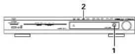
Select the Dolby Surround Pro Logic (Pro Logic x ) mode.


(Main unit) (Remote control unit)
- The Dolby Pro Logic II (Pro Logic IIIx) indicator lights.
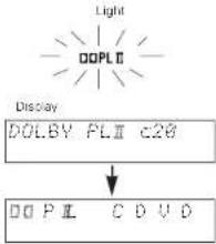
3
Play a program source with the mark.
- For operating instructions, refer to the manuals of the respective components.

4
Select the surround parameter mode.

Display

(Remote control unit)

* To perform this operation from the remote control unit, check that the mode selector switch is set to "AUDIO".
5
Select the optimum mode for the source.
(Remote control unit)


7
Set the various surround parameters.
(Remote control unit)
8
Press the SURROUND PARAMETER button to finish surround parameter mode.

(Hemote control unit)
6
Select the various parameters. (See "Surround parameters (1)" for a description of the various parameters.)

(Remote control unit)

DOLBY PL II MUSIC
OPTIONAL PARAMETERS
PANDRAMA ON < OFF
DIMENSION CENTER WIDTH
Default Yes
表决结果:同意9票。
gaxe
DTS NEO:6 mode

1
Select the function to which the component you want to play is connected.
Example: DVD


(Main unit) (Remote control unit)
2
Select the DTS NEO:6 mode.


(Main unit) (Remote control unit)
- The mode switches as shown below each time the button is pressed.

Play a program source.
3
4
Select the surround parameter mode.

Display
MODE cinema
(Remote control unit)
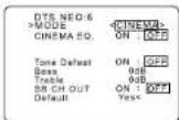
To perform this operation from the remote control unit, check that the mode selector switch is set to "AUDIO".

5
Select the optimum mode for the source.

(Remote control unit)


6
Select the various parameters.

(Remote control unit)
ENGLISH
7
Set the various surround parameters.
(Remote control unit)
8
Press the SURROUND PARAMETER button to finish surround parameter mode.

(Remote control unit)
Surround parameters ①
Pro Logic II (IIx) Mode:
• The Cinema mode is for use with stereo television shows and all programs encoded Dolby Surround.
- The Music mode is recommended as the standard mode for autosound music systems (no video), and is optional for A/V systems.
- The Pro Logic mode offers the same robust surround processing as original Pro Logic in case, the source contents is not of optimum quality.
Select one of the modes ("cinema", "music" or "game").
Panorama Control:
This mode extends the front stereo image to include the surround speakers for an exciting "wraparound" effect with side wall imaging. Select "OFF" or "ON".
Dimension Control:
This control gradually adjust the soundfield either towards the front or towards the rear. The control can be set in 7 steps from 0 to 6.
Center Width Control:
This control adjust the center image so it may be heard only from the center speaker; only from the left/right speakers as a phantom image; or from all three front speakers to varying degrees. The control can be set in 8 steps from 0 to 7.
DTS NEO:6 Mode:
• Cinema
This mode is optimum for playing movies. Decoding is performed with emphasis on separation performance to achieve the same atmosphere with 2-channel sources as with 6.1-channel sources. This mode is effective for playing sources recorded in conventional surround formats as well, because the in-phase component is assigned mainly to the center channel (C) and the reversed phase component to the surround (SL, SR and SB channels).
• Music
This mode is suited mainly for playing music. The front channel (FL and FR) signals bypass the decoder and are played directly so there is no loss of sound quality, and the effect of the surround signals output from the center (CI and surround (SL, SR and SB) channels add a natural sense of expansion to the sound field.
CENTER IMAGE (0.0 to 0.5: default 0.2):
The center image parameter for adjusting the expansion of the center channel in the DTS NEO:6 MUSIC mode has been added.
Surround parameters ②
CINEMA EQ. (Cinema Equalizer):
The Cinema EQ function gently decreases the level of the extreme high frequencies, compensating for overly bright sounding motion picture soundtracks. Select this function if the sound from the front speakers is too bright. This function only works in the Dolby Pro Logic IIx. Dolby Digital, DTS Surround, DTS NEO:6 and WIDE SCREEN modes. (The same contents are set for all operating modes.)
D.COMP. (Dynamic Range Compression):
Motion picture soundtracks have tremendous dynamic range (the contrast between very soft and very loud sounds). For listening late at night, or whenever the maximum sound level is lower than usual, the Dynamic Range Compression allows you to hear all of the sounds in the soundtrack (but with reduced dynamic range). (This only works when playing program sources recorded in Dolby Digital or DTS.) Select one of the four parameters ('OFF', "LOW", "MID" (middle) or "HI" (high). Set to OFF for normal listening.
LFE (Low Frequency Effect):
This sets the level of the LFE (Low Frequency Effect) sounds included in the source when playing program sources recorded in Dolby Digital or DTS.
If the sound produced from the subwoofer sounds distorted due to the LFE signals when playing Dolby Digital or DTS sources when the peak limiter is turned off with the subwoofer peak limit level setting (system setup menu), adjust the level as necessary.
Program source and adjustment range:
1. Dolby Digital: -10 dB to 0 dB
2. DTS Surround: -10 dB to 0 dB
* When DTS encoded movie software is played, it is recommended that the LFE LEVEL be set to 0
dB for correct DTS playback
When DTS encoded music software is played, it is recommended that the LFE LEVEL be set to -10 dB for correct DTS playback.
TONE:
This adjusts the tone control. This can be set individually for the separate snroud mode other than Pure direct and direct mode.
AFDM (Auto Flag Detect Mode):
ON ..... This function only works with software on which a special identification signal is recorded. This software is scheduled to go on sale in the future.
This is a function for automatically playing in the 6.1-channel mode using the surround back speakers if the software is recorded in DTS-ES or in the normal 5.1 channel mode without using the surround back speakers when the software is not recorded in DTS-ES.
OFF.....Set the "OFF" mode to perform 6.1-channel playback with conventional 5.1-channel sources or sources on which the identification signal described below is not recorded.
SB CH OUT:
(1) (Multi channel source)
"OFF"....Playback is conducted without using the surround back speaker.
"NON MTRX" ....The same signals those of the surround channels are output from the surround back channels.
"MTRX ON" ....Surround back channel is reproduced using digital matrix processing.
"ES MTRX"......When playing DTS signals, the surround back signals undergo digital matrix processing for playback.
"ES DSCRT"......When a signal identifying the source as a discrete 6.1-channel source is included
in the DTS signals, the surround back signals included in the source are played.
"PLⅡx Cinema"......Processing is performed with the Cinema mode of the PLⅡx decoder and the Surround Back channel is reproduced.
"PL IIx Music"....Processing is performed with the Music mode of the PL IIIx decoder and the Surround Back channel is reproduced.
(2) (2ch source)
"OFF"....Playback is conducted without using the surround back speaker.
"ON"....Playback is conducted using the surround back speaker.
NOTE: This operation can be performed directly using the "SURROUND BACK" button on the main unit's panel.
Dolby Virtual Speaker mode
- The Dolby Virtual Speaker mode is a mode using 3D sound technology from Dolby Laboratories to achieve multi-channel surround sound using only two speakers for the front channels.
- With two speakers for the front channels, one of two modes can be selected: Reference or Wide.
- The Dolby Virtual Speaker mode can be used not only with Dolby Digital and DTS multi-channel sources but also with 2-channel sources. With 2-channel sources, one of two 2-channel modes can be selected. Virtual 1 (Dolby Pro Logic II Cinema) and Virtual 2 (Dolby Pro Logic).
- With a multi-channel speaker configuration (for example 5.1 channels), the Dolby Virtual Speaker mode provides different effects according to the speaker configuration.
[1] Playing Dolby Digital and DTS surround sound (with digital inputs only)
©Applicable sources
- Digital input
Dolby Digital multi-channel sources DTS sources
![DENON DHT-550SD - [1] Playing Dolby Digital and DTS surround sound (with digital inputs only) - 1](/content/2026/05/1021875/images/7994010c0bb0ca31ac4289252aecf3958bc6b5255459f8f0bbaad42bcca64753.jpg)

1
Select the input source.
Playback with a digital input
①Select an input source set to digital (COAXIAL/OPTICAL) (see page 14).
Example: DVD
![DENON DHT-550SD - [1] Playing Dolby Digital and DTS surround sound (with digital inputs only) - 3](/content/2026/05/1021875/images/767718f8d0656be3a227de8ec4b68f4a4241b33971386542a6b714138d70e748.jpg)
(Main unit)
![DENON DHT-550SD - [1] Playing Dolby Digital and DTS surround sound (with digital inputs only) - 4](/content/2026/05/1021875/images/f24fbde27d1259f508954d353b5133113aaa63ff85e5d5dbf4a5574dbb391020.jpg)
(Remote control unit)
② Set the input mode to "AUTO", "PCM" or "DTS".
![DENON DHT-550SD - [1] Playing Dolby Digital and DTS surround sound (with digital inputs only) - 5](/content/2026/05/1021875/images/54d0039a5be46450459224fe2dbc7b3ef8cebb9b5592853cff787cd81523cd7c.jpg)
(Remote control unit)
2
Set the surround mode to "DOLBY VIRTUAL SPEAKER".
![DENON DHT-550SD - [1] Playing Dolby Digital and DTS surround sound (with digital inputs only) - 6](/content/2026/05/1021875/images/0f962ca9957150bd4e295928bc998ab9dd7b0f2aea0733353f6a31380b91af6f.jpg)
(Main unit)
![DENON DHT-550SD - [1] Playing Dolby Digital and DTS surround sound (with digital inputs only) - 7](/content/2026/05/1021875/images/9a96367df0db96eadf900103088dbe1026dad64e2c9632f397c3c551c180c93e.jpg)
(Main unit)
![DENON DHT-550SD - [1] Playing Dolby Digital and DTS surround sound (with digital inputs only) - 8](/content/2026/05/1021875/images/af4743325cb31fa3f4e26f01427496be551d6eef600620b21d79e8a412af60b2.jpg)
(Remote control unit)
![DENON DHT-550SD - [1] Playing Dolby Digital and DTS surround sound (with digital inputs only) - 9](/content/2026/05/1021875/images/bb8ee9e9c76c2ca5e3fe8d03ba9e2e97a3f6ce7f00e07137234a0ec98ff41d83.jpg)
3
Play a program source including the dts mark.
• The Dolby Digital indicator lights when playing Dolby Digital sources.
• The DTS indicator lights when playing DTS sources.
* This switches automatically according to the format of the playback source.
4
Display the surround parameters for that source.

(Remote control unit)
5
Select and set the surround parameters.
* If nothing is done for 6 seconds from when the parameter is displayed, the normal display reappears.

Remote control unit
Setting the DOLBY VS mode

The selected mode flashes.
* The mode is not displayed if it cannot be selected.
*D.COMP. setting

Setting the LFE level

* The LFE level can be adjusted in steps of 1 dB between -10 dB and 0 dB.
DEFAULT setting

- When "YES" is selected, the settings are restored to the factory defaults.
* When the surround parameters are displayed, use the ▲ and ▼cursor buttons on the remote control unit to switch to previous or following items.
* Once the surround parameters have been set, stop operating the buttons. After several seconds, the normal display roappears and the settings are automatically entered.
Surround parameters ③
DOLBY VS (Dolby Virtual Speaker mode):
• REF (Reference mode)
This is the standard mode.
• WIDE (Wide mode)
This mode expands the front channel sound field
D.COMP. (Dynamic range compression):
- This parameter adjusts the dynamic range of the Dolby Digital sound. When listening with the volume turned relatively low, at night for example, set this to the "HI" side to lower the peak of the sound and amplify the quieter sounds, narrowing the dynamic range and making the sound easier to listen to. Set to "OFF" to turn this function off.

LFE (Low Frequency Effect):
• Program source and adjustment range
-
Dolby Digital : -10 dB to 0 dB
-
DTS Surround: -10 dB to 0 dB
-
When Dolby Digital encoded software is played, it is recommended that the LFE LEVEL be set to 0 dB for correct Dolby Digital playback.
- When DTS encoded movie software is played, it is recommended that the LFE LEVEL be set to 0 dB for correct DTS playback.
- When DTS encoded music software is played, it is recommended that the LFE LEVEL be set to -10 dB for correct DTS playback.
ENGLISH
[2] 2-channel mode settings
- When 2-channel signals are input, one of two playback modes can be selected and set according to the 2-channel mode setting. Virtual 1 or Virtual 2. (The Virtual 1 mode is set by factory default.) Virtual 1: 2-channel sources are played in virtual surround using Dolby Pro Logic II Cinema processing. Virtual 1: 2-channel sources are played in virtual surround using Dolby Pro Logic processing.
![DENON DHT-550SD - [2] 2-channel mode settings - 1](/content/2026/05/1021875/images/9b378dfe7a7cac99cca1677d7464d43115526e94b5dad56fb69311a82b325077.jpg)
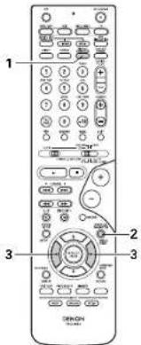
Surround parameters ④
VIRTUAL1 (Virtual 1 mode):
In this mode, 2-channel sources are played with Dolby Pro Logic II Cinema processing. This mode is suited for playing movie sources recorded in Dolby Surround and regular stereo sources.
VIRTUAL2 (Virtual 2 mode):
In this mode, 2-channel sources are played with Dolby Pro Logic processing. This mode is compatible with regular Dolby Pro Logic playback. With it, the recorded playback image of sources recorded in Dolby Surround is recreated faithfully.
1 Set the surround mode to "DOLBY VIRTUAL SPEAKER" ("DOLBY VS"). • The normal display reappears after the surround mode is displayed.

(Main unit) (Main unit)

(Remote control unit)
2 Press the SURROUND PARAMETER button and select the 2-channel mode.

(fermate control unit)
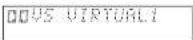
This can be selected if there is no digital input signal, if the digital input is a PCM or Dolby Digital 2-channel signal and if the input is analog.
3 Turn the SURROUND/SELECT control on the main unit or use the ◀ and ▶cursor buttons on the remote control unit to select the desired 2-channel mode.

(fermate control unit)
VIRTUAL 1-VIRTUAL 2
■ Press the SURROUND PARAMETER button to finish surround parameter mode.
NOTES:
- The 2-channel mode cannot be set when Dolby Digital or DTS 5.1 channel signals.
- The 2-channel mode is set and stored in the memory individually for the different functions.
This unit is equipped with a high performance DSP (Digital Signal Processor) which uses digital signal processing to synthetically recreate the sound field. One of 6 preset surround modes can be selected according to the program source and the parameters can be adjusted according to the conditions in the listening room to achieve a more realistic, powerful sound. These surround modes can also be used for program sources not recorded in Dolby Surround Pro Logic, Dolby Digital or DTS.
Surround modes and their features
| 1 | SCH/SCH STEREO | In this mode, the signals of the front left channel are output from the left surround channel, the signals of the front right channel are output from the right surround channel, and the same (in-phase) component of the left and right channels is output from the center channel. This mode provides all speaker surround sound, but without directional steering effects, and works with any stereo program source. |
| 2 | MONO MOVIE (NOTE 1) | Select this when watching monaural movies for a greater sense of expansion. |
| 3 | ROCK ARENA | Use this mode to achieve the feeling of a live concert in an arena with reflected sounds coming from all directions. |
| 4 | JAZZ CLUB | This mode creates the sound find of a live house with a low ceiling and hard walls. This mode gives jazz a very vivid realism. |
| 5 | VIDEO GAME | Use this to enjoy video games sources. |
| 6 | MATRIX | Select this to emphasize the sense of expansion for music sources recorded in stereo. Signals consisting of the difference component of the input signals (the component that provides the sense of expansion) processed for delay are output from the surround channel. |
* Depending on the program source being played, the effect may not be very noticeable.
In this case, try other surround modes, without worrying about their names, to create a sound field suited to your tastes.
NOTE 1: When playing sources recorded in monaural, the sound will be one-sided if signals are only input to one channel (left or right), so input signals to both channels. If you have a source component with only one audio output (monophonic camcorder, etc.) obtain a "Y" adapter cable to split the mono output to two outputs, and connect to the L and R inputs.
NOTE:
DIRECT, STEREO, DOLBY PRO LOGICII, DOLBY VIRTUAL SPEAKER and DOLBY HEADPHONE mode can be used when playing PCM signals with a sampling frequency of 96 kHz (such as from DVD-Video discs that contain 24 bit, 96 kHz audio). If such signals are input during playback in the other surround modes, the mode automatically switches to STEREO.
Personal Memory Plus
This set is equipped with a personal memorize function that automatically memorizes the surround modes and input modes selected for the input different sources. When the input source is switched, the modes set for that source last time it was used are automatically recalled. The surround parameters, tone control settings and playback level balance for the different output channels are memorized for each surround mode:
DSP surround simulation
- To operate the surround mode and surround parameters from the remote control unit.
1
Select the surround mode for the input channel.

(Remote control unit)
The surround mode switches in the following order each time the DSP SIMULATION button is pressed:

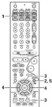
2

(Demate control unit)
To enter the surround parameter setting mode, press the SURROUND PARAMETER button.
The surround parameter switches in the following order each time the SURROUND PARAMETER button is pressed for the different surround modes.

3

Remote control unit
Select the various parameters.
4
Remote control unit
Adjust the parameter settings.
5

Remote control unit
Press the SURROUND PARAMETER button to finish surround parameter mode.
- Operating the surround mode from the main unit's panel.
1
To select the surround mode, press the SURROUND MODE button then operate the selector.
Turn the SELECT knob to select the surround mode.


(Main unit)(Main unit)
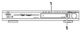
- When turned clockwise


- When turned counterclockwise


NOTES:
- When playing PCM digital signals or analog signals in the 5CH/6CH STEREO, ROCK ARENA, JAZZ CLUB, VIDEO GAME, MONO MOVIE or MATRIX surround modes and the input signal switches to a digital signal encoded in Dolby Digital, the Dolby surround mode switches automatically. When the input signal switches to a DTS signal, the mode automatically switches to DTS surround.
- When the "5CH/6CH STEREO" mode is selected, the display differs according to the Surround Back CH ON/OFF
Surround Back CH ON: 6CH STEREO
Surround Back CH OFF: 5CH STEREO
Surround parameters ⑤
ROOM SIZE:
This sets the size of the sound field.
There are five settings: "small", "mod.s" (medium-small), "medium", "mod.l" (medium-large) and "large", "small" recreates a small sound field, "large" a large sound field.
EFFECT LEVEL:
This sets the strength of the surround effect.
The level can be set in 15 steps from 1 to 15.
DELAY TIME:
In the matrix mode only, the delay time can be set within the range of 0 to 300 ms.
ENGLISH
■Surround modes and parameters
C: Signal
x; No signal
①: Turned on or off by speaker configuration setting
C: Able
×; Unable
^x Only for 2 ch contents
■Differences in surround mode names depending on the input signals
| input signals | |||||||
| DTS DOLBY DIGITAL Around Mode | |||||||
| ANALOG | LINEAR FOM | DTS (S 1 dB) | DTS (80/24 S 1 dB) | DTS (W 1 dB) | H2 dB (C 1 dB) | S 1 dB | |
| FIRE DIRIC, DIRIC | ○ | ○ | ○ | ○ | ○ | ○ | ○ |
| STREO | ○ | ○ | ○ | ○ | ○ | ○ | ○ |
| DTS SURROUND | DTS NEOD | DTS NEOD | XOTS/PLinkChrome Music | XOTS/PLinkChrome Music | XOTS/PLinkChrome Music | × | × |
| DOLBY SURROUND | +DOBY PROLOGIC II | +DOBY PROLOGIC II | √ | × | × | +DOBY PROLOGIC II | +DOBY DIGITAL FX |
| +DOBY PROLOGIC IX | +DOBY PROLOGIC IX | +DOBY PROLOGIC IX | +DOBY DIGITAL FX | ||||
| +Chemo MusicCarrel | +Chemo MusicCarrel | +Chemo MusicCarrel | +Chemo MusicCarrel | ||||
| DST SIMULATION | ○ | ○ | √ | × | × | × | × |
C: Selectable
* : The surround mode name differs depending on the "SB CH OUT" surround parameter setting
The surround mode name differs depending on the input signal.
: Not selectable
| Mode | Signals and adjustability in the different modes | ||||||||||||
| Parameter (default values are shown in parentheses) | |||||||||||||
| SURROUND PARAMETER | PRO LOGIC II MUSIC MODE ONLY | NEOR MUSIC MODE ONLY | When playing Delby Diga / OTIS signals | ||||||||||
| CON-CON-CON | MODI | DEORDER | CIRMA-HD | ROOM S/A | HHD LEVEL | DELAY TIME | SURYOUND WALL | PARWARIWA | DIMENSION | CENTER WITH | CENTER IMAGE | 0.00M2 | |
| DH-FCI | X | X | X | X | X | X | X | X | X | X | X | X | O IOHH |
| SIF-KD | O I3KB | X | X | X | X | X | X | X | X | X | X | X | O IOHH |
| EXTRNAL INFU | O I3KB | X | X | X | X | X | X | X | X | X | X | X | X |
| DOI-RY PRO LOGC II | O I3KB | O I3HEAW | X | C IERP Note45 | X | X | X | O | O IOHH | O GB | O GB | X | O IOHH |
| DOI-RY PRO LOGC II+ | O I3KB | O I3HEAW | X | C IERP Note46 | X | X | X | O | O IOHH | O GB | O GB | X | O IOHH |
| DIY-ROSE | O I3KB | O I3HEAW | X | C IERP Note47 | X | X | X | O | X | X | X | O OZI | O IOTTI |
| DOI-RY DIGITAL | O I3KB | X | X | C IERP | X | X | X | O | X | X | X | X | O IOTTI |
| DIY-SURROUND IOTS PER WTRK-B 1 | O I3KB | X | X | C IERP | X | X | X | O | X | X | X | X | O IOTTI |
| SMCK-S-HKD | O I3KB | X | X | X | X | X | X | O | X | X | X | X | O IOTTI |
| ROCK-ASHNA | O I3KB | X | X | X | O/Medunt | O CB | X | O | X | X | X | X | O IOTTI |
| JAY-CLUB | O I3KB | X | X | X | O/Medunt | O CB | X | O | X | X | X | X | O IOTTI |
| VIUHO GAMA | O I3KB | X | X | X | O/Medunt | O CB | X | O | X | X | X | X | O IOTTI |
| MONO MONI | O I3KB | X | X | X | O/Medunt | O CB | X | O | X | X | X | X | O IOTTI |
| MATRIX | O I3KB | X | O | X | X | X | O DOGreen | O | X | X | X | X | O IOTTI |
| DOLOY VIRTUAL SPREAD | O I3KB | O I3HEAW | O NUTUAL 1 | X | X | X | X | X | X | X | X | X | O IOTTI |
| DOLOY H-ALPHONF | O I3KB | O I3HEAW | O I3HEAW | X | X | X | X | X | X | X | X | X | O IOTTI |
(Note 1) Only without surround speakers
(Note 2) 2 cm source only
(Note 3) Cinema, DOLEY PL Mode only
(Note 4) Cinema Mode only
○: Adjustable
X: Not adjustable
Playback using the Dolby Headphone mode
- The AVR-550SD is equipped with the Dolby Headphone mode, a technology developed jointly by Dolby Laboratories and Lake Technology for achieving 3D sound over regular headphones.
- The Dolby Headphone mode is set when headphones are connected to the AVR-550SD's headphones jack.
- There are actually four Dolby Headphone modes creating different sound field effects: DH1, DH2, DH3 and Bypass (normal stereo playback).
- The Dolby Headphone mode is compatible with Dolby Digital and DTS multi-channel sources. With 2-channel sources, playback in the Cinema, Music 1 and Music 2 modes can be selected with the 2-channel mode setting.
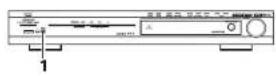

1 Connect headphones (sold separately) to the headphones jack.
- When headphones are plugged in, the output to the speakers is automatically turned off and no sound is produced from the speakers.

2 Press the surround parameter button and display the surround parameters.
* When the function is set to DVD, this is also shown on the display.

Remote control unit
2 Set the various surround parameters.
* If nothing is done for 6 seconds from when the parameter is displayed, the normal display reappears.
(Remote control unit)
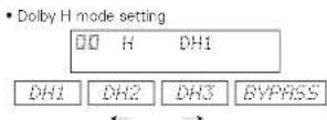

- The mode switches as shown below each time a button is operated.

※ Can be selected when there is no signal or when playing a 2-channel source.
There are also the same parameters as those described under "Do by Virtual Speaker mode" (see page 27), namely:
CD.COMP. setting
©LFE level setting
DEFAULT setting
※ When the surround parameters are displayed, use
the ▲ and ▼ cursor buttons on the remote control unit to switch to previous or following items.
ENGLISH
15 LISTENING TO THE RADIO
Auto tuning


1 Set the input source to "TUNER".

(Main unit) (Remote control unit)
2 Watching the display, press the BAND button to select the desired band (AM or FM) and to set the auto tuning mode.


[Main unit] (Remote control unit)

3 Press the TUNING - or - button.


(Main unit)
(Remote control unit)
• Automatic searching begins, then stops when a station is tuned in.
NOTE:
- When in the auto tuning mode on the FM band, the "STEREO" indicator lights on the display when a stereo broadcast is tuned in. At open frequencies, the noise is muted and the "TUNED" and "STEREO" indicators turn off.
Manual tuning
1 Set the input function to "TUNER".

(Main unit) (Remote control unit)

2 Watching the display, press the BAND button to select the desired band (AM or FM).


(Main unit) (Remote control unit)
3 Press the BAND button to set the manual tuning mode. Check that the display's "AUTO" indicator turns off.

[Main unit] (Remote control unit)

4 Press the TUNING + or - button to tune in the desired station. The frequency changes continuously when the button is held in.

[Main unit]
- When the manual tuning mode is set, FM stereo broadcasts are received in monaural and the "STEREO" indicator turns off.
Preset stations

Preparations:
Use the "Auto tuning" or "Manual tuning" operation to tune in the station to be preset in the memory.
1

(Romote control unit)
2

(Romote control unit)
NOTE:
- Please make sure the "AUDIO" position of the slide switch on the remote control unit.
3

(Hemote control unit)
4

(Remate control unit)
Press the CHANNEL + or - button to select the desired preset channel (1 to 8).
* To preset other channels, repeat steps 1 to 4. A total of 40 broadcast stations can be preset - 8 stations (channels 1 to 8) in each of blocks A to E.
Checking the preset stations
- The preset (broadcast) stations can be checked on the on screen display (OSD).
1 Press the ON SCREEN/DISPLAY button repeatedly until the "Tuner Preset Stations" screen appears on the OSD.

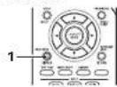

Recalling preset stations

1

(Remote control unit)
NOTE:
- Please make sure the "AUDIO" position of the slide switch on the remote control unit.
2

(Fermote control unit)
Watching the display, press the SHIFT button to select the preset memory block.
Watching the display, press the CHANNEL + or - button to select the desired preset channel.
RDS (Radio Data System)
RDS (works only on the FM band) is a broadcasting service which allows station to send additional information along with the regular radio program signal.
The following three types of RDS information can be received on this unit:
Program Type (PTY)
PTY identifies the type of RDS program.
The program types and their displays are as follows:
| NEWS | News | ROCK M | Rock Music | PHONE IN | Phone In |
| AFFAIRS | Current Affairs | EASY M | Easy Listening Music | TRAVEL | Trovol |
| INFO | Information | LIGHT M | Light Classical | LEISURE | Leisure |
| SPORT | Sports | CLASSICS | Serious Classical | JAZZ | Jazz Music |
| EDUCATE | Education | OTHER M | Other Music | COUNTRY | Country Music |
| DRAMA | Drama | WEATHER | Weather | NATION M | National Music |
| CULTURE | Culture | FINANCE | Finance | OLDIES | Oldies Music |
| SCIENCE | Science | CHILDREN | Children's programmes | FOLK M | Folk Music |
| UNITED | Varieso | SOCIAL | Social Affairs | DOCUMENT | Documentary |
| POP M | Pop Music | RELIGION | Religion |
■Traffic Program (TP)
TP identifies programs that carry traffic announcements.
This allows you to easily find out the latest traffic conditions in your area before you leaving home.
Radio Text (RT)
RT allows the RDS station to send text messages that appear on the display.
NOTE: The operations described below using the RDS, PTY and RT buttons will not function in areas in which there are no RDS broadcasts.
ENGLISH
RDS search
Use this function to automatically tune to FM stations that provide RDS service.
1

Set the input function to "TUNER".
(Fermote control unit)
2

Press the RDS button until "RDS SEARCH" appears on the display.
(Fermote control unit)
* The main unit's display switches as follows each time the RDS buttons are pressed.
Display

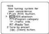
This is the screen when operated
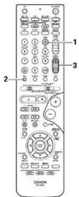
3

Press the CHANNEL + (up) or - (down) button to automatically begin the RDS search operation.
(Remote control unit)
If no RDS stations is found with above operation, all the reception band are searched.
4
When a broadcast station is found, that station's nammo appears on the display.
5
To continue searching, repeat step 3. If no other RDS station is found when all the frequencies are searched, "NO RDS" is displayed.

This is the screen when operated.
PTY search
Use this function to find RDS stations broadcasting a designated program type (PTY). For a description of each program type, refer to "Program Type (PTY)".
1

Remote control unit
2

Set the input function to "TUNER".
Press the RDS button until "PTY SEARCH" appears on the display.
Remote control unit
The main unit's display switches as follows each time the RDS buttons are pressed.
Display

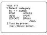
This is the screen when annotated.
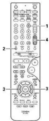
3

Watching the display, press the ◀ and ▶ cursor buttons to call out the desired program type.
Herivate control unit?

This is the screen other button
5
The station name is displayed on the display after searching stops.
6
To continue searching, repeat step 4. If no other station broadcasting the designated program type is found when all the frequencies are searched, "NO PROGRAMME" is displayed.

This is the screen when operated.
4

(Remote control unit)
Press the CHANNEL + (up) or - (down) button to automatically begin the PTY search operation.
If there is no station broadcasting the designated program type with above operation, all the reception bands are searched.
TP search
Use this function to find RDS stations broadcasting traffic program (TP stations).
1

(3) Senate: social unit
Set the input function to "TUNER".
2

(Semate control unit)
Press the RDS button until "TP SEARCH" appears on the display.
* The main unit's display switches as follows each time the RDS buttons are pressed.
Display


This is the screen when operated
3

Remate contro un ti
Press the CHANNEL + (up) or - (down) button TP search begins.
If no TP station is found with above operation, all the reception bands are searched.
4
The station name is displayed on the display after searching stops.
5
To continue searching, repeat step 3. If no other TP station is found when all the frequencies are searched, "NO PROGRAMME" is displayed.

This is the screen when operated.

RT (Radio Text)
"RT" appears on the display when radio text data is received.
When the RDS button is pressed until "RT" appears on the display while receiving an RDS broadcast station, the text data broadcast from the station is displayed. To turn the display off, use the ◀ and ▶ cursor buttons on the remote control unit.
This is the screen when operated.

16 USING THE SLEEP TIMER
- The sleep timer can be used to set the time (up to 60 minutes) after which the power will be set to the standby mode.
- The power can automatically be set to the standby mode after a specific amount of time (minutes).

1
Press the SETUP button to display the System Setup Menu.

2
Use the 📄down) button select "|.Sleep timer", then press the ENTER button.

3
Press Ctrl or [up] to select the desired time.
4
Press the ENTER button. • The "SLEEP" indicator lights.

NOTE:
- To cancel the sleep timer or change the set time, repeat steps 1 to 4 under "Using the sleep timer".
ENGLISH
17 LAST FUNCTION MEMORY
- This unit is equipped with a last function memory which stores the input and output setting conditions as they were immediately before the power is switched off.
This function eliminates the need to perform complicated resettings when the power is switched on. - The unit is also equipped with a back-up memory. This function provides approximately one week of memory storage when the main unit's power switch is off and with the power cord disconnected.
18 INITIALIZATION OF THE MICROPROCESSOR
When the indication of the display is not normal or when the operation of the unit does not show the reasonable result, the initialization of the microprocessor is required by the following procedure.
1 Press the power button to set the standby mode, then unplug the set's power cord from the wall power outlet.
2 Hold the following 5CH/6CH STEREO button and DIRECT/STEREO button after 30 second, and plug the AC cord into the outlet.
3 Check that the entire display is flashing with an interval of about 1 second, and release your fingers from the 2 buttons and the microprocessor will be initialized.

NOTES:
- If step 3 does not work, start over from step 1
- If the microprocessor has been reset, all the button settings are reset to the default values (the values set upon shipment from the factory).
19 USING THE SYS-550SD (DHT-550SD ONLY)
CAUTIONS ON HANDLING
When installing, carefully examine the place and method of installation for safety.
When using a stand, brackets, etc., follow the instructions included with the stand or brackets and check for safety before installing and using. Denon will accept no responsibility for damages or accidents caused by the unit falling.
Cautions on Installation - Speaker System (SC-A3L, SC-C3L)
The quality of the sound produced from the speaker system is affected by the size and type (Japanese or Western) of the room, as well as by the method of installation. Consider the points listed below before installing the speaker system.
Note that placing the speaker system on the same stand or shelf as a record player may result in howling.
If there is a wall, glass door, etc., directly in front of or behind the speaker system, cover the wall or door with a thick curtain to prevent resonance and reflection.
The SC-A3L and SC-C3L speaker systems are of the low-leakage-flux type and can be used near televisions, but depending on the TV there may be color blotching on the picture. If this happens, turn off the TV's power, wait 15 to 30 minutes; then turn the TV's power back on. The TV's automatic degaussing circuit should reduce the blotching on the picture. If blotching persists, move the speaker further away.
The center speaker (SC-C3L) is equipped with anti-slip pads upon shipment from the factory. If necessary, however, also apply the included anti-slip pads (cork, approximately 2 mm thick).
When placing the satellite speaker system (SC-A3L) on a stand, etc., stick the included anti-slip pads (cork, approximately 2 mm thick) at the four corners of the bottom surface. (Refer to the illustration below.)
[Satellite speaker system (illustration of bottom of SC-A3L)]
Stick the anti-slip pads (cork, approximately 2 mm thick) here.

Stick the anti-slip pads (cork, approximately 2 mm thick) here.
When mounting the satellite speaker system (SC-A3L) on a stand or bracket, M5 nuts are inserted into the bottom of the satellite speaker system (SC-A3L) at intervals of 60 mm. When mounting, following the instructions in the manual included with the speaker stand or ceiling mount bracket, and be sure to install properly and securely.
When the satellite speaker system (SC-A3L) is mounted on a ceiling mount bracket, it is turned upside down due to the installation angle. The Denon mark is also turned upside down, so detach the speaker net and reattach it in the opposite direction.
CAUTION:
• To ensure safety, do not place any objects on top or lean objects against the speaker system.
- The speaker may topple down or fall if force is applied to the sides. Be particularly careful to avoid this, as this could cause injury or other serious accidents.
WARNING
- When installing the speaker systems on the ceiling or wall, to ensure safety, have specialists do the installation work.
- Be sure to fasten the speaker cords to a wall, etc., to prevent people from tripping over them or otherwise pulling on them accidentally, causing the speaker systems to fall.
- Be sure to check for safety after installing the speaker systems. Afterwards, perform safety inspections at regular intervals to be sure there is no danger that the speaker systems will fall. Denon will accept no responsibility for damages or accidents caused by inappropriate choice of the place of installation or improper installation procedures.
Other Cautions (SC-A3L, SC-C3L)
Note that color blotching may occur on a TV, etc., due to interaction with the speaker system if there is a magnet or an object generating magnetic force nearby.
Examples: (a) When there are magnets on the door of the rack, stand, etc.
(b) When a health device, etc., equipped with magnets is placed nearby.
(c) When toys or other objects using magnets are placed nearby.
Note that the illustrations in this instructions may differ from the actual set for explanation purposes.
■Be sure to keep the operating instructions.
After reading these operating instructions, store them in a safe place. We also recommend filling in the necessary items on the back cover.
Cautions on Installation – Active subwoofer (DSW-3L)
Note that placing the active subwoofer on the same stand or shelf as a record player may result in howling.
The DSW-3L active subwoofer is a Lowiaakaga-Flux type speaker system and can be used near televisions, but depending on the TV there may be color blotching on the picture. If this happens, turn off the TV's power, move the TV and subwoofer a little apart, wait 15 to 30 minutes, then turn the TV's power back on. The TV's automatic degaussing circuit should reduce the blotching on the picture. If blotching persists, move the subwoofer and TV further away from each other.
■Install on a firm, flat floor to prevent accidents due to toppling down.
■Do not place a record player, CD player or other AV device on top of the subwoofer.
Other Cautions - Active subwoofer (DSW-3L)
The built-in amplifier of the active subwoofer (DSW-3L) includes a muting circuit. The output signal is strongly attenuated for several seconds after the power is turned on. If the volume is adjusted during this time, the output may be extremely high when the muting circuit is deactivated. Be sure to wait for the muting circuit to be deactivated before adjusting the volume.
Note that color blotching may occur on a TV, etc., due to interaction with the subwoofer if there is a magnet or an object generating magnetic force nearby.
Examples: (a) When there are magnets on the door of the rack, stand, etc.
(b) When a health device, etc., equipped with magnets is placed nearby.
(c) When toys or other objects using magnets are placed nearby.
Note that the illustrations in this instructions may differ from the actual set for explanation purposes.
■Be sure to keep the operating instructions.
After reading these operating instructions, store them in a safe place. We also recommend filling in the necessary items on the back cover.
WARNING:
- Be sure to fasten the power cord to a wall, etc., to prevent people from tripping over it or otherwise pulling on it accidentally, causing the subwoofer to fall.
PART NAMES AND FUNCTIONS
Active subwoofer (DSW-3L) rear panel
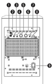
① Line input connector (LINE IN)
- Connect this to the AV amplifier's pre-out connector ("SUBWOOFER", "MONO OUT", etc.) using the included connection cord (3-meter RCA pin cord).
② Line output connector (LINE OUT)
- The signal input to the line input connector is output as such from here in parallel.
- When using two active subwoofers, connect the other active subwoofer's line input connector to this connector.
3 Phase selector switch (PHASE)
- This switches the phase of the output signal with respect to the input signal.
- Normally use the subwoofer with this switch set at the "NORM." position. If the continuity between the sound of the active subwoofer and the left and right speakers seems unnatural, try switching to the "REV." position, and set the switch to the position in which the sound is most natural.
4 LF direct switch (LF DIRECT)
- When using the active subwoofer connected to a Dolby Digital- or dts-compatible AV amplifier, if this function is turned on the signals bypass the active subwoofer's crossover and volume adjustment circuits, resulting in purer, higher quality sound. Note that when this is done the crossover adjustment control (6) and volume adjustment control (5) will no longer function.
When using in combination with the AVR-550SD, we recommend turning the LF DIRECT switch on and setting the AVR 550SD's crossover frequency to 150 Hz.
ENGLISH
⑤ Crossover adjustment control (CROSSOVER)
- This control only functions when the LF DIRECT switch (4) is set to the "OFF" position.
- This control sets the upper limit of the frequencies reproduced by the active subwoofer.
- Setting criteria 50Hz: For left/right speakers with diameters of 20 cm or greater 100Hz: For left/right speakers with diameters between 10 and 25 cm 200Hz: For left/right speakers with diameters of 12 cm or less
- When using a Dolby Digital- or dts-compatible AV amplifier, we recommend turning the LF DIRECT switch (1) to the "ON" position and not using this function.
- "Dolby" is a trademark of the Dolby Laboratories Licensing Corporation.
- "dts" is a trademark of Digital Theater Systems.
6 Volume adjustment control (LEVEL)
- This control any functions when the LF DIRECT switch (4) is set to the "OFF" position.
- Use this control to adjust the volume of the active subwoofer.
- When turned clockwise | from the center position, the volume of the active subwoofer increases, and when turned counterclockwise ( ) the volume decreases. Set to the desired position.
7 Auto standby selector switch (AUTO STANDBY)
ON: The auto standby function is activated OFF: The auto standby function is deactivated
Auto Standby Function
The amplifier is automatically set to the standby mode if no signal is input for 5 to 11 minutes, thereby saving electricity. The power turns on immediately when a signal is input.
8 Status Indicator
- The two-colored LED indicates the active subwoofer's operating status, as follows: Power "ON"....Lights green Auto power off (standby mode)....Lights red Power "OFF"....LED off Protective circuit activated.....Flashing red
9 Power switch (POWER)
- The power turns on when this switch is set to the "ON" position. - Several seconds are required for the set to begin operating. This is because the set includes a built-in muting circuit to prevent noise when the power switch is turned on and off. - When set to the "OFF" position, the power turns off.
CONNECTIONS
CAUTION:
- Do not plug the AC power cord into an AC power outlet until all connections have been completed.
- Check the left and right channels and be sure to interconnect them properly, L (left) to L, R (right) to R.
- Plug the AC power cord in securely. An insecure connection could cause noise.
- Note that clamping pin-plug cords and power cords together or running pin-plug cords near the power transformer could result in humming or noise.
- Check the polarities of the speakers and amplifier and be sure to interconnect property. Connect the red terminal on the speaker to the “+” speaker terminal on the amplifier, the black terminal on the speaker to the “-” speaker terminal on the amplifier.
(1) Connecting the line input connector (LINE IN)
- Connect this to the pre-out connector for the active subwoofer on the AV amplifier ("SUBWOOFER PRECUT", "MONO OUT", etc.) using the included connection cord (3-meter RCA pin cord).

CAUTION:
- If this connector is connected to the pre-out connector for the surround center channel of a stereo amplifier or AV surround amplifier, only the center channel's bass sound will be produced, so the overall bass sound will be insufficient.
(2) Connecting the speaker terminals
* Read the amplifier's operating instructions carefully before connecting, and be sure to use properly.
* When connecting the equipment or changing the connections, be sure to turn the equipment's power switches off and unplug the power plugs from the AC power outlets.
■Connecting the speaker terminals
-
Peel off the sheath from the tip of the connection cord, then firmly twist the wires by hand so that they do not stick out and cause short-circuits.
-
Loosen the terminal by turning it counterclockwise, then insert the connection cord into the hole in the speaker terminal.
-
Turn the terminal clockwise to tighten it. Check that none of the core wires are sticking out of the hole.


The red side is the "+" side, the black side the "-" side.
To “+” side on amplifier (copper colored core wire)
NOTE: Make sure the core wires do not touch each other.
To “-” side on amplifier (silver colored core wire)
Once the connections are completely, gently pull on the speaker cords to make sure they are securely connected.
CAUTION:
- Be careful to interconnect the positive (+", red) and negative (−", black) sides and the left and right speakers properly.
- Connect the side of the included connection cord with the copper colored core wires to the red speaker terminal.
- To prevent circuit problems, never short-circuit copper and silver colored core wires or the left and right cords.

When installing, carefully examine the place and method of installation for safety. When using a stand, brackets, etc., follow the instructions included with the stand or brackets and check for safety before installing and using. Denon will accept no responsibility for damages or accidents caused by the unit falling.
USING THE ACTIVE SUBWOOFER (DSW-3L)
-
Set the power switch to the "ON" position.
-
When the unit's AC power cord is plugged into a switched AC outlet on the amplifier, if the power switch is left at the "ON" position, the unit's power turns on and off automatically when the amplifier's power is turned on and off.
-
If the AC power cord is not plugged into a switched AC outlet on the amplifier, set the unit's power switch to the "ON" position after turning on the amplifier's power. When turning the power off, set the unit's power switch to the "OFF" position before turning off the amplifier's power.
-
Adjust the volume using the volume adjustment control.
※ For details, see "PART NAMES AND FUNCTIONS".
REMOVING THE SPEAKER NET (SC-A3L, SC-C3L)
^3 The net on the front of the speaker systems (SC-A3L, SC-C3L) can be removed.
• To remove, grasp both sides of the net and pull forward.
- To mount, line up the holes in the four corners of the speaker net with the projecting pieces in the four corners of the cabinet and press in.
ENGLISH
20 ADDITIONAL INFORMATION
Optimum surround sound for different sources
There are currently various types of multi-channel signals (signals or formats with more than two channels).
■Types of multi-channel signals
Dolby Digital, Dolby Pro Logic, DTS, high definition 3-1 signals Japan MUSE Hi-Vision audiol, DVD-Audio, SACD (Super Audio CD), MPEG multi-channel audio, etc.
"Source" here does not refer to the type of signal format but the recorded content. Sources can be divided into two major categories.
■Types of sources
• Movie audio
Signal's created to be played in movie theaters. In general sound is recorded to be played in movie theaters equipped with multiple surround speakers, regardless of the format (Dolby Digital, DTS, etc.).
Movie theater sound field

Listening room sound field

In this case it is important to achieve the same sense of expansion as in a movie theater with the surround channels.
To do so, in some cases the number of surround speakers is increased (to four or eight) or speakers with bipolar or dipolar properties are used.
/SL: Surround L channel
SR: Surround R channel
SB. Surround back channel (1 spkr or 2 spkrs)
Multiple surround speakers
(For 6.1 channel system)
- Other types of audio
These signals are designed to recreate a 350° sound field using three to five speakers.

In this case the speakers should surround the listener from all sides to create a uniform sound field from 360°, Ideally the surround speakers should function as "point" sound sources in the same way as the front speakers.
These two types of sources thus have different properties, and different speaker settings, particularly for the surround speakers, are required in order to achieve the ideal sound.
Surround back speakers
A 6.1-channel system is a conventional 5.1-channel system to which the "surround back" (SBI channel) has been added. This makes it easy to achieve sound positioned directly behind the listener, something that was previously difficult with sources designed for conventional multi surround speakers. In addition, the acoustic image extending between the sides and the rear is narrowed, thus greatly improving the expression of the surround signals for sounds moving from the sides to the back and from the front to the point directly behind the listening position.
Change of positioning and acoustic image
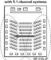
Movement of acoustic image from SR to SL
Change of positioning and acoustic image
with 6.1-channel systems

Movement of acoustic image from SR to SB to SL
With this set, speaker(s) for 1 or 2 channels are required to achieve a 6.1-channel system (DTS-ES, etc.). Adding these speakers, however, increases the surround effect not only with sources recorded in 6.1 channels but also with conventional 2-to 5.1-channel sources. All the Denon original surround modes (see page 28) are compatible with 7.1-channel playback, so you can enjoy 6.1-channel sound with any signal source.
■Number of surround back speakers
Though the surround back channel only consists of 1 channel of playback signals for 6.1-channel sources IDTS-ES, etc.I, we recommend using two speakers. When using speakers with dipolar characteristics in particular, it is essential to use two speakers.
Using two speakers results in a smoother blend with the sound of the surround channels and better sound positioning of the surround back channel when listening from a position other than the center.
■Placement of the surround left and right channels when using surround back speakers
Using surround back speakers greatly improves the positioning of the sound at the rear. Because of this, the surround left and right channels play an important role in achieving a smooth transition of the acoustic image from the front to the back. As shown on the diagram above, in a movie theater, the surround signals are also produced from diagonally in front of the listeners, creating an acoustic image as if the sound were floating in space.
To achieve these effects, we recommend placing the speakers for the surround left and right channels slightly more towards the front than with conventional surround systems. Doing so sometimes increases the surround effect when playing conventional 5.1-channel sources in the 6.1 surround or DTS-ES Matrix 6.1 mode. Check the surround effects of the various modes before selecting the surround mode.
ENGLISH
Speaker setting examples
Here we describe a number of speaker settings for different purposes. Use these examples as guides to set up your system according to the type of speakers used and the main usage purpose.
1. DTS-ES compatible system (using surround back speakers)
(1) Basic setting for primarily watching movies
This is recommended when mainly playing movies and using regular single way or 2-way speakers for the sorround speakers.

- Set the front speakers with their front surfaces as flush with the TV or monitor screen as possible. Set the center speaker between the front left and right speakers and no further from the listening position than the front speakers.
- Consult the owner's manual for your subwoofer for advice on placing the subwoofer within the listening room.
- If the surround speakers are direct-radiating (monopolar) then place them slightly behind and at an angle to the listening position and parallel to the walls at a position 60 to 90 centimeters (2 to 3 feet) above ear level at the prime listening position.
- When using two surround back speakers, place them at the back facing the front at a narrower distance than the front left and right speakers. When using one surround back speaker, place it at the rear center facing the front at a slightly higher position (0 to 20 cm) than the surround speakers.
- We recommend installing the surround back speaker(s) at a slightly downward facing angle. This effectively prevents the surround back channel signals from reflecting off the monitor or screen at the front center, resulting in interference and making the sense of movement from the front to the back less sharp.

As seen from the side
(2) Setting for primarily watching movies using diffusion type speakers for the surround speakers
For the greatest sense of surround sound envelopment, diffuse radiation speakers such as bipolar types, or dipolar types, provide a wider dispersion than is possible to obtain from a direct radiating speaker (monopolar). Place these speakers at either side of the prime listening position, mounted above ear level.
Path of the surround sound from the speakers to the listening position

Surround back speakers (spkr at 7 wards)
As seen from above
- Set the front speakers, center speaker and subwoofer in the same positions as in example (1).
- It is best to place the surround speakers directly at the side or slightly to the front of the viewing position, and 60 to 90 cm above the ears.
- Same as surround back speaker installation method (1).
Using dipolar speakers for the surround back speakers as well is more effective. Connect the surround speakers to the surround speaker lacks. - The signals from the surround channels reflect off the walls as shown on the diagram at the left, creating an enveloping and realistic surround sound presentation.
For multi-channel music sources however, the use of bipolar or bipolar speakers mounted at the sides of the listening position may not be satisfactory in order to create a coherent 360 degree surround sound field. Connect another pair of direct radiating speakers as described in example (3) and place them at the rear corners of the room facing towards the prime listening position.

As seen from the side
2. When not using surround back speakers
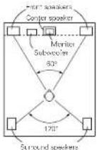
As seen from above
- Set the front speakers with their front surfaces as flush with the TV or monitor screen as possible. Set the corner speaker between the front left and right speakers and no further from the listening position than the front speakers.
- Consult the owner's manual for your subwoofer for advice on placing the subwoofer within the listening room.
- If the surround speakers are direct-radiating (monopolar) then place them slightly behind and at an angle to the listening position and parallel to the walls at a position 60 to 90 centimeters (2 to 3 feet) above ear level at the prime listening position.

As seen from the side
Surround
The AVR-550SD is equipped with a digital signal processing circuit that lets you play program sources in the surround mode to achieve the same sense of presence as in a movie theater.
Dolby Surround
(1) Dolby Digital
Dolby Digital is the multi-channel digital signal format developed by Dolby Laboratories. Dolby Digital consists of up to "5.1" channels - front left, front right, center, surround left, surround right, and an additional channel exclusively reserved for additional deep bass sound effects the Low Frequency Effects - LFE - channel, also called the ".1" channel, containing bass frequencies of up to 120 Hz. Unlike the analog Dolby Pro Logic format, Dolby Digital's main channels can all contain full range sound information, from the lowest bass, up to the highest frequencies - 22 kHz. The signals within each channel are distinct from the others, allowing pinpoint sound imaging, and Dolby Digital offers tremendous dynamic range from the most powerful sound effects to the quietest, softest sounds, free from noise and distortion.
■Dolby Digital and Dolby Pro Logic
| Comparison of home surround systems. | Dolby Digital | Dolby Pro Logic |
| No. recorded channels (elements) | 5.1 cm | 2 cm |
| No. playback channels | 5.1 cm | 4 cm |
| Playback channels (max.) | L, R, C, SL, SR, SW | L, R, C, S (SW - recommended) |
| Audio processing | Digital discrete processing Dolby Digital encoding/encoding | Analog marks processing Dolby Surround |
| High frequency playback limit of surround channel | 20 kHz | 7 kHz |
ENGLISH
■Dolby Digital compatible media and playback methods
Marks indicating Dolby Digital compatibility: ☐ ☐ ☐ ☐
The following are general examples. Also refer to the player's operating instructions.
| Media | Dolby Digital output jacks | Playback method reference page |
| I.D (VDP) | Coaxial Dolby Digital RF output jack 3.1 | Set the input mode to "AUTO" (Page 19) |
| DVD | Optical or coaxial digital output [same as for PCVI] | Set the input mode to "AUTO" (Page 19) |
| Others [satosits broadcasts, CATV, etc.) | Optical or coaxial digital output [same as for PCMI] | Set the input mode to "AUTO" (Page 19) |
* 1 Please use a commercially available adapter when connecting the Dolby Digital RF output jack of the LD player to the digital input jack.
Please refer to the instruction manual of the adapter when making connection.
- Some DVD digital outputs have the function of switching the Dolby Digital signal output method between "bit stream" and "(convert to) PCM". When playing in Dolby Digital surround on the AVR-550SD, switch the DVD player's output mode to "bit stream". In some cases players are equipped with both "bit stream + PCM" and "PCM only" digital outputs. In this case connect the "bit stream + PCM" jacks to the AVR-550SD.
(2) Dolby Pro Logic IIx
- Dolby Pro Logic IIx furthers the matrix decoding technology of Dolby Pro Logic II to decode audio signals recorded on two channels into up to 7.1 playback channels, including the surround back channel. Dolby Pro Logic IIx also allows 5.1 channel sources to be played in up to 7.1 channels.
The mode can be selected according to the source. The Music mode is best suited for playing music, the Cinema mode for playing movies, and the Game mode for playing games. The Game mode can only be used with 2-channel audio sources.
(3) Dolby Pro Logic II
- Dolby Pro-Logic II is a new multi-channel playback format developed by Dolby Laboratories using feedback logic steering technology and offering improvements over conventional Dolby Pro Logic circuits.
- Dolby Pro Logic II can be used to decode not only sources recorded in Dolby Surround ( ^* ) but also regular stereo sources into five channels (front left, front right, center, surround left and surround right) to achieve surround sound.
- Whereas with conventional Dolby Pro Logic the surround channel playback frequency band was limited, Dolby Pro Logic II offers a wider band range (20 Hz to 20 kHz or greater). In addition, the surround channels were monaural (the surround left and right channels were the same) with previous Dolby Pro Logic, but Dolby Pro Logic II they are played as stereo signals.
- Various parameters can be set according to the type of source and the contents, so it is possible to achieve optimum decoding (see page 24, 251).
* Sources recorded in Delay Surround
These are sources in which three or more channels of surround have been recorded as two channels of signals using Dalby Surround encoding technology.
Dolby Surround is used for the sound tracks of movies recorded on DVDs, LDs and video cassettes to be played on stereo VCRs, as well as for the stereo broadcast signals of FM radio, TV, satellite broadcasts and cable TV.
Decoding these signals with Dolby Pro Logic II makes it possible to achieve multi-channel surround playback. The signals can also be played on ordinary stereo equipment, in which case they provide normal stereo sound.
There are two types of DVD Dolby surround recording signals.
①2-channel PCM stereo signals
②2-channel Dolby Digital signals
When either of these signals is input to the AVR-550SD, the surround mode is automatically set to Dolby Pro Logic II when the "DOLBY/DTS SURROUND" mode is selected.
■Sources recorded in Dolby Surround are indicated with the logo mark shown below.
Dolby Surround support mark: ☐ DOLBY SURROUND
Manufactured under license from Dolby Laboratories.
"Dolby", "Pro Logic" and the double-D symbol are trademarks of Dolby Laboratories.
DTS Digital Surround
Digital Theater Surround (also called simply DTS) is a multi-channel digital signal format developed by Digital Theater Systems.
DTS offers the same "5.1" playback channels as Dolby Digital (front left, front right and center, surround left and surround right) as well as the stereo 2-channel mode. The signals for the different channels are fully independent, eliminating the risk of deterioration of sound quality due to interference between signals, crosstalk, etc.
DTS features a relatively higher bit rate as compared to DSB Digital (1234 kbps for CDs and LDs, 1536 kbps for DVDs) so it operates with a relatively low compression rate. Because of this the amount of data is great, and when DTS playback is used in movie theaters, a separate CD-ROM synchronized with the film is played.
With LDs and DVDs, there is of course no need for an extra disc; the pictures and sound can be recorded simultaneously on the same disc, so the discs can be handed in the same way as discs with other formats. There are also music CDs recorded in DTS. These CDs include 5.1-channel surround signals (compared to two channels on current CDs). They do not include picture data, but they offer surround playback on CD players that are equipped with digital outputs (PCM type digital output required).
DTS surround track playback offers the same intricate, grand sound as in a movie theater, right in your own listening room.
■DTS compatible media and playback methods
Marks indicating DTS compatibility:


The following are general examples. Also refer to the player's operating instructions.
| Media | Dolby Digital output jacks | Playback method inference page |
| CD | Optical or coaxial digital output (same as for PCM) ☑ | Set the input mode to "AUTO" or "DTS" (page 19). Never set the mode to "ANALCG" or "PCM". ☑ 1 |
| LD (VDF) | Optical or coaxial digital output (same as for PCM) ☑ | Set the input mode to "AUTO" or "DTS" (page 19). Never set the mode to "ANALCG" or "PCM". ☑ 1 |
| DVD | Optical or coaxial digital output (same as for PCM) ☑ | Set the input mode to "AUTO" or "DTS" (page 19). |
*1 DTS signals are recorded in the same way on CDs and LDs as PCM signals. Because of this, the un- decoded DTS signals are output as random "hissey" noise from the CD or LD player's analog outputs. If this noise is played with the amplifier set at a very high volume, it may possibly cause damage to the speakers. To avoid this, be sure to switch the input mode to "AUTO" or "DTS" before playing CDs or LDs recorded in DTS. Also, never switch the input mode to "ANALOG" or "PCM" during playback. The same holds true when playing CDs or LDs on a DVD player or LD/DVD compatible player. For DVDs, the DTS signals are recorded in a special way so this problem does not occur.
2 The signals provided at the digital outputs of a CD or LD player may undergo some sort of internal signal processing (output level adjustment, sampling frequency conversion, etc.). In this case the DTS-encoded signals may be processed erroneously, in which case they cannot be decoded by the AVR-550SD, or may only produce noise. Before playing DTS signals for the first time, turn down the master volume to a low level, start playing the DTS disc, then check whether the DTS indicator on the AVR-550SD (see page 23) lights before turning up the master volume.
3 A DVD player with DTS-compatible digital output is required to play DTS DVDs. A DTS Digital Output logo is featured on the front panel of compatible DVD players. Recent DENON DVD player models feature DTS-compatible digital output – consult the player's owner's manual for information on configuring the digital output for DTS playback of DTS-encoded DVDs.
Manufactured under license from Digital Theater Systems, Inc. US Pat. No. 5,451,942, 5,956,674, 5,974,380, 5,978,762 and other world-wide patents issued and pending.
"DTS", "DTS-ES Extended Surround" and "Nec:6" are trademarks of Digital Theater Systems, Inc. ©1996, 2000 Digital Theater Systems, Inc. All Rights Reserved.
DTS-ES Extended Surround™
DTS-ES Extended Surround is a new multi-channel digital signal format developed by Digital Theater Systems Inc. While offering high compatibility with the conventional DTS Digital Surround format, DTS-ES Extended Surround greatly improves the 360-degree surround impression and space expression thanks to further expanded surround signals. This format has been used professionally in movie theaters since 1999.
In addition to the 6.1 surround channels (FL, FR, C, SL, SR and LFF), DTS-ES Extended Surround also offers the SB (Surround Back, sometimes also referred to as "surround center") channel for surround playback with a total of 6.1 channels. DTS-ES Extended Surround includes two signal formats with different surround signal recording methods, as described below.
■DTS-ES™ Discrete 6.1
DTS-ES Discrete 6.1 is the newest recording format. With it, all 6.1 channels (including the SB channel) are recorded independently using a digital discrete system. The main feature of this format is that because the SL, SB and SB channels are fully independent, the sound can be designed with total freedom and it is possible to achieve a sense that the acoustic images are moving about freely among the background sounds surrounding the listener from 360 degrees.
Though maximum performance is achieved when sound tracks recorded with this system are played using a DTS-ES decoder, when played with a conventional DTS decoder the SR channel signals are automatically down-mixed to the SL and SR channels, so none of the signal components are lost.
■DTS-ES™ Matrix 6.1
With this format, the additional SB channel signals undergo matrix encoding and are input to the SL and SR channels beforehand. Upon playback they are decoded to the SL, SR and SB channels. The performance of the encoder used at the time of recording can be fully matched using a high precision digital matrix decoder developed by DTS, thereby achieving surround sound more faithful to the producer's sound design aims than with conventional 5.1- or 6.1-channel systems.
In addition, the bit stream format is 100% compatible with conventional DTS signals, so the effect of the Matrix 6.1 format can be achieved even with 5.1-channel signal sources. Of course it is also possible to play DTS-ES Matrix 6.1 encoded sources with a DTS 5.1-channel decoder.
When DTS-ES Discrete 6.1 or Matrix 6.1 encoded sources are decoded with a DTS-ES decoder, the format is automatically detected upon decoding and the optimum playing mode is selected. However, some Matrix 6.1 sources may be detected as having a 5.1-channel format, so the DTS-ES Matrix 6.1 mode must be set manually to play these sources.
(For instructions on selecting the surround mode, see page 23.)
The DTS-ES decoder includes another function, the DTS Neo:6 surround mode for 6.1-channel playback of digital PCM and analog signal sources.
■DTS Neo:6™ surround
This mode applies conventional 2-channel signals to the high precision digital matrix decoder used for DTS-ES Matrix 6.1 to achieve 6.1-channel surround playback. High precision input signal detection and matrix processing enable full band reproduction (frequency response of 20Hz to 20kHz or greater) for all 6.1 channels, and separation between the different channels is improved to the same level as that of a digital discrete system.
DTS Neo:6 surround includes two modes for selecting the optimum decoding for the signal source.
• DTS Neo:6 Cinema
This mode is optimum for playing movies. Decoding is performed with emphasis on separation performance to achieve the same atmosphere with 2-channel sources as with 6.1-channel sources.
This mode is effective for playing sources recorded in conventional surround formats as well, because the in-phase component is assigned mainly to the center channel (C) and the reversed phase component to the surround (SL, SR and SB channels).
• DTS Neo:6 Music
This mode is suited mainly for playing music. The front channel IFL and FRI signals bypass the decoder and are played directly so there is no loss of sound quality, and the effect of the surround signals output from the center (C) and surround ISL, SR and SBI channels add a natural sense of expansion to the sound field.
DTS 96/24
The sampling frequency, number of bits and number of channels used for recording of music, etc., in studios has been increasing in recent years, and there are a growing number of high quality signal sources, including 96 kHz/24 bit 5.1-channel sources.
For example, there are high picture/sound quality DVD video sources with 96 kHz/24 bit stereo PCM audio tracks. However, because the data rate for these audio tracks is extremely high, there are limits to recording them on two channels only, and since the quality of the pictures must be restricted it is common to only include still pictures.
In addition, 96 kHz/24 bit 5.1-channel surround is possible with DVD audio sources, but DVD audio players are required to play them with this high quality.
DTS 96/24 is a multi-channel digital signal format developed by Digital Theater Systems Inc. in order to deal with this situation.
Conventional surround formats used sampling frequencies of 48 or 44.1 kHz, so 20 kHz was about the maximum playback signal frequency. With DTS 96/24, the sampling frequency is increased to 96 or 88.2 kHz to achieve a wide frequency range of over 40 kHz.
In addition, DTS 96/24 has a resolution of 24 bits, resulting in the same frequency band and dynamic range as 96 kHz/24 bit PCM.
As with conventional DTS Surround, DTS 96/24 is compatible with a maximum of 5.1 channels, so sources recorded using DTS 96/24 can be played in high sampling frequency, multiple channel audio with such normal media as DVD videos and CDs.
Thus, with DTS 96/24, the same 96 kHz/24 bit multi-channel surround sound as with DVD-Audio can be achieved while viewing DVD-Video images on a conventional DVD-Video player (☑). Furthermore, with DTS 96/24 compatible CDs, 88.2 kHz/24 bit multi-channel surround can be achieved using normal CD/LD players (☑).
Even with the high quality multi-channel signals, the recording time is the same as with conventional DTS surround sources.
What's more, DTS 96/24 is fully compatible with the conventional DTS surround format, so DTS 96/24 signal sources can be played with a sampling frequency of 48 kHz or 44.1 kHz on conventional DTS or DTS-ES surround decoders (12).
※1: A DVD player with DTS digital output capabilities (for CD/LD players, a player with digital outputs for conventional DTS CDs/LDs) and a disc recorded in DTS 96/24 are required.
※2: The resolution is 24 or 20 bits, depending on the decoder.
ENGLISH
Dolby Virtual Speaker
Dolby Virtual Speaker technology uses proprietary technology of Dolby Laboratories to create a virtual surround sound field using only two speakers for the front channels, allowing the user to experience sound as if surround speakers were actually being used.
■Features of Dolby Virtual Speaker sound
Accurate surround sound field positioning
The virtual surround speakers are positioned at 105° to the left and 105° to the right.
- Multi-channel programs played according to the producer's intentions
The sound of the different channels is played in the position set upon mixing. For example, sound set at the rear left is heard from the rear left.
©Stereo programs played in surround
The Dolby Pro Logic II circuit is used together with the Dolby Virtual Speaker circuitry to create a rich virtual surround sound field with stereo programs as well.
◎Selecting the listening mode
Two listening modes are provided: Reference and Wide.

Reference mode Wide mode

2 front channels

Virtual sound field created with the Dolby Virtual Speaker mode
With the AVR-550SD, playback in the Dolby Virtual Speaker mode is possible with other speaker configurations as well.
- 3 speakers (2 front channels + center) : Reference/Wide modes
- 4 speakers (2 front channels + 2 surround channels) : Wide mode
- 5 speakers (2 front channels + center + 2 surround channels) : Wide mode
Dolby Headphone
Dolby Headphone is a 3D sound technology developed jointly by Dolby Laboratories and Lake Technology of Australia achieving surround sound with regular headphones.
Normally when using headphones all the sounds are sounded in the head, making it uncomfortable to listen with headphones for long periods of time. Dolby Headphone simulates speaker playback in a room and positions the sound sources to the front or the sides, outside of the head, achieving a powerful sound similar to that of a movie theater or home theater. This technology is aimed mainly at multi-channel audio or video equipment including Dolby Digital or Dolby Pro Logic Surround decoding functions and operates inside a high performance digital signal processing chip (DSP).
The Dolby Headphone mode can be used not only with multi-channel sources but also with stereo programs.
21 TROUBLESHOOTING
If a problem should arise, first check the following.
-
Are the connections correct?
-
Have you operated the receiver according to the Operating Instructions?
-
Are the speakers, turntable and other components operating property?
If this unit is not operating properly, check the items listed in the table below. Should the problem persist, there may be a malfunction.
Disconnect the power immediately and contact your store of purchase.
| Symptom Cause Measures Page | ||||
| Common problems when starting in the CD, recess, taps and TM Innozzles, etc. | DISPLAY not ill and sound not produced when power switch set to on. | Power cord not plugged in securely. | Check the insertion of the power cord plug. | 6 |
| DISPLAY it but sound not produced. | Speaker cords not securely connectedImproper position of the audio function button.Volume control set to minimum.VUTING is on.Digital signals not input Digital input selected. | Connect securely.Set to a suitable position.Turn volume up to suitable level.Switch off MUTING.Input digital signals or select input jacks to which digital signals are being input. | 9, 1019202119 | |
| DISPLAY not ill and power indicator is flashing rapidly. | Speaker terminals are short circuited.Block the ventilation holes of the set.The unit is occurring at continuous high power conditions and/or inadequate ventilation. | Switch power off, connect speakers properly, then switch power back on.Turn off the set's power, then ventilate it well to cool it down.Once the set is cooled down, turn the power back on.Turn off the set's power, then ventilate it well to cool it down.Once the set is cooled down, turn the power back on. | 9, 1033 | |
| Sound produced only from one channel. | Incomplete connection of speaker cords.Incomplete connection of input/output cords. | Connect securely.Connect securely. | 9, 106 - 10 | |
| Positions of instruments reversed during stereo playback. | Reverse connections of left and right spockers or left and right input/output cards. | Check left and right connections. 10 | ||
| Symptom Cause | Features Page | |||
| When playing records | Humming noise produced when record is playing. | TV or radio transmission antenna nearby.Tumble and speaker systems too close together.Foor is unsafe and vibrates easily. | Contact your store of purchase. | — |
| Howling noise produced when volume is high. | Separate as much as possible.Use cushions to absorb speaker vibrations transmitted by floor. It turnable is not equipped with insulators, use audio insulators (commonly available) | — | ||
| Sound is distorted. | Stylos pressure too weak.Dust or cirt on stylus.Cartridge defective. | Apply proper stylus pressure.Check stylus.Replace cartridge | —— | |
| Remote control unit | This unit does not operate properly when remote control unit is used. | Batteries good.Remove control unit too far from this unit.Obstace between this unit and remote control unit.Different button is being pressed.and ends of battery inserted in reverse. | Replace with new batteries.Vave cluster.Remove obstacle.Press the proper buttonInsert batteries properly. | 1010——10 |
| Speaker spectrum (GVS-5505X) | Active subwoofer (DGV3U) LED does not light and no sound is produced when power is turned on. | AC power plug is not securely connected. | Check the connection of the AC power plug. | 37 |
| Active subwoofer (DGV3U) LED lights but no sound is produced. | Cords are not securely connected.Volume adjustment control is turned all the way down. | Connect security.Turn the control end set it to the desired position. | 9, 10 | |
| Active subwoofer (DGV3U) LED flashes and no sound is produced. | Protective circuit has been activated due to excess input or rise in temperature. | Set the power switch to the "OFF" position, wait at least 1 minute, then set the power switch back to the "ON" position. If the problem persists, unplug the AC power cord from the AC power outlet and contact your store of purchase. | — | |
| Active subwoofer (DGV3U) Sound is distorted. | Volume level is too high.Sound is being distorted on connected amplifier. | Turn the volume adjustment control counterclockwise to over the volume.Do not amplify the bass sound on the amplifier. (Lower the amplifier's bass adjustment control or volume.) | 37, 38 | |
| Active subwoofer (DGV3U) Oscillation loud continuous sound produced. | Volume of active subwoofer or amplifier set too high. | Lower the volume of the active subwoofer or amplifier. | 37, 38 |
For improvement purposes, specifications and design are subject to change without notice.
ENGLISH
ENGLISH
22 SPECIFICATIONS
AVR-550SD
Audio section
Power amplifier Rated output:
Front: 100 W + 100 W (6 Ω/chms, 1 kHz with 10% T.H.D.I
Center: 100 W (6 Ω/ohms, 1 kHz with 10% T.H.D.)
Surround: 100 W + 100 W (6 Ω/ohms, 1 kHz with 10% T.H.D.)
Surround Back: 100 W (6 Ω/ohms, 1 kHz with 10% T.H.D.)
Front Center Surround Surv Back: 6 \~ 16 Probms
Output terminals:
• Analog
Input sensitivity / input impedance:
Frequency response:
S/N ratio: 95 dB (IHF-A weighted) (D)
Rated output: 1.1 V (Subwoofer Pre Output, 30 Hz)
200 mV / 47 kΩ/kohms
10 Hz \~ 60 kHz: +1, -3 dB (EXTERNAL IN)
ALIN
■Video section
Standard video jacks
Input / output level and impedance:
Frequency response
• S-video jacks
Input / output level and impedance:
Frequency response:
Color component video jacks
Input / output level and impedance:
1 Va-p. 75 O/ohms
5 Hz \~ 10 MHz — +1, -3 dB
Y (brightness) signal — 1 Vp-p, 75 Ω/ohms
C (color) signal — 0.286 Vp-p, 75 Ω/ohms
5 Hz - 10 MHz — +1, -3 dB
Frequency response:
Tuner section
Receiving Range
Usable Sensitivity:
S/N ratio:
Y (brightness) signal — 1 Vp-p, 75 Ω/ohms
P_B / Ca (blue) signal — 0.7 Vp-p, 75 / ohms
Pr / Cr (red) signal — 0.7Vp-p, 75 Ω/ohms
5 Hz \~ 30 MHz — +1, -3 dB
Total Harmonic Distortion:
[FM] (note: μV at 75 Ω/ohms, 0 dBf=1 × 10 ^-15 W)
87.50 MHz \~ 108.00 MHz
1.0 μV (11.2 dBfl
MONO 74 dB (IHF-A weighted)
STEREO 65 dB (IHF-A weighted)
MONO 0.3 % (1 kHz)
STEREO 0.4 % (1 kHz)
[AM]
522 kHz \~ 1611 kHz
18 μV
Timer Section
Timer
General
Power supply:
Power consumption:
Sleep timer: 60 minutes, maximum
Maximum external dimensions:
Mass:
AC 230 V, 50 Hz
75 W
1 W May (Standby)
External dimensions:
Mass:
R6P/AA Type (three batteries)
165 g (including batteries)
^x For purposes of improvement, specifications and design are subject to change without notice.
- SYS-550SD
Satellite speaker system (SC-A3L)
Type:
Speakers:
Input impedance:
Max. input
Frequency range:
Dimensions:
Mass
■Center speaker system (SC-C3L)
Type:
Speakers:
Input impedance:
Max. input
Frequency range:
Dimensions:
Mass:
■Active subwoofer (DSW-3L)
Type:
Speaker:
Speaker impedance:
Frequency range:
Rated output power:
Input impedance:
Crossover frequency:
Power supply:
Power consumption:
Dimensions:
Mass:
2-way, 3-speakers
Closed box / Low-leakage-flux
5.7 cm cone bass-mid x 2
1.9 cm super-high range x 1
6 Ω/ohms
40 watts (IECI
100 watts (PEAK)
120 Hz \~ 90 kHz
Closed box / Low-leakage-flux
5.7 cm cone bass-mid x 2
1.9 cm super-high range x 1
6 Ω/ohms
40 watts (IEC)
100 watts (PEAK)
120 Hz - 90 kHz
210.048 x 72 (H) x 161 (D) mm
210 kg 1.1 kg
1-way, 1-speaker
Reflex box / Low-leakage-flux
Built-in amplifier
16 cm cone woofer x 1
4 O/ohms
25 Hz - 200 Hz
(1 F Direct / Off)
95 watts
(4) Ohms load 55Hz THD 0.7%
(420mm load, barz, 1.113.5.7 %), 22 kOhmpa
22 Kazkommis 50 Hz 300
50 Hz \~ 200 Hz (variable)
(LF Direct / Off)
230V / 50Hz (Europe)
53 watts (IEC)
< 1 watt (Standby)
232(W) × 452(H) × 395(D) mm
(including base)
11.2 kg (including base)
DEUTSCH
natural_image
Technical line drawing of a cabinet and adjacent enclosure with no visible text or symbols* 10 cm oder mehr
Test Tone Start Yes<
Level Clear Yes
3


Digital In Assignment
17 COAXIAL : < VCR > 18 OPTICAL1 : DVD/VDP 19 OPTICAL2 : TVIDBS
2

22 Auto Surround Mode
ON > OFF
2

3
DBS/CABLE......ABC (CABLE)
CINEMA EQ. (Cinema-Equalizer)

(Remote control unit)
Recalling preset stations

1

DTS-ES Extended Surround™
Total Harmonic Distortion:
Timer-Bereich
Timer-Funktionen:
Allgemeines
Netzteil:
Stromaufnahmen:
Printed in China 511 4202 003

- CAUTION
- RISK OF ELECTRIC SHOCK
- DO NOT OPEN
- CAUTION: TO REDUCE THE RISK OF ELECTRIC SHOCK, DO NOT REMOVE COVER (OR BACK). NO USER SERVICEABLE PARTS INSIDE. REFER SERVICING TO QUALIFIED SERVICE PERSONNEL.
- WARNING: TO REDUCE THE RISK OF FIRE OR ELECTRIC SHOCK, DO NOT EXPOSE THIS APPLIANCE TO RAIN OR MOISTURE.
- • DECLARATION OF CONFORMITY
- "SERIAL NO.
- INTRODUCTION
- CONTENTS
- SYS-550SD
- BEFORE USING
- CAUTIONS ON INSTALLATION
- CAUTIONS ON HANDLING
- ENGLISH
- FEATURES
- Dolby Virtual Speaker compatibility
- Dolby Digital EX decoder system
- Dolby Pro Logic IIx compatibility
- Dolby Pro Logic II Game mode compatibility
- DTS-ES Extended Surround and DTS Neo:6
- DTS 96/24 compatibility
- On Screen Display
- Video Conversion Function
- Dolby Digital
- 10.DTS (Digital Theater Systems)
- Component Video Switching
- Auto Surround Mode
- PART NAMES AND FUNCTIONS
- Front Panel
- Remote control unit
- READ THIS FIRST
- SETTING UP THE SPEAKER SYSTEMS
- ■Speaker system layout
- CONNECTIONS
- Connecting the audio components
- Connecting the DIGITAL jacks
- NOTES:
- NOTE:
- Connecting video components
- Connecting a video component equipped with S-Video jacks
- Connecting a Video Component Equipped with Color Difference (Component Y, PR/CR, PB/CB) Video Jacks (DVD Player)
- Connecting the external input (EXT. IN) jacks
- Speaker system connections
- Speaker Impedance
- Protector circuit
- Note on speaker impedance
- Connections
- - Precautions when connecting speakers
- USING THE REMOTE CONTROL UNIT
- SETTING UP THE SYSTEM
- Before setting up the system
- Setting the type of speakers
- - Parameters
- - About the surround back speaker
- Caution:
- Setting the Subwoofer mode and Crossover Frequency
- — Assignment of low frequency signal range —
- — Crossover Frequency —
- — Subwoofer mode —
- Setting the delay time
- Preparations:
- 1
- 2
- 3
- Setting the channel level
- 4
- Setting the Digital In Assignment
- Setting the Video In Assignment
- Setting the Auto Surround Mode
- Setting the Ext. In SW Level
- Setting the On Screen Display (OSD)
- Auto Tuner Presets
- After setting up the system
- Operating DENON audio components
- Preset memory
- Operating component stored in the preset memory
- Video deck (VCR) system buttons
- Digital broadcast satellite (DBS) tuner and cable (CABLE) system buttons
- Monitor TV (TV) system buttons
- Punch Through
- OPERATION
- Before operating
- Playing the input source
- Input mode selection function
- Example: Stereo
- 5
- Input mode display
- Input signal display
- Playback using the external input (EXT. IN) jacks
- Playing audio sources
- DIRECT mode
- STEREO mode
- After starting playback
- [1] Adjusting the sound quality (tone)
- [2] Listening over headphones
- [3] Turning the sound off temporarily (MUTING)
- [4] Combining the currently playing sound with the desired image
- [5] Checking the currently playing program source, etc.
- 13
- SURROUND
- Before playing with the surround function
- Dolby Digital mode (only with digital input) and DTS Surround (only with digital input)
- ■Dialogue Normalization
- Dolby Surround Pro Logic II (Pro Logic IIx) mode
- Surround parameters ①
- Pro Logic II (IIx) Mode:
- Panorama Control:
- Dimension Control:
- Center Width Control:
- DTS NEO:6 Mode:
- • Cinema
- • Music
- CENTER IMAGE (0.0 to 0.5: default 0.2):
- Surround parameters ②
- CINEMA EQ. (Cinema Equalizer):
- D.COMP. (Dynamic Range Compression):
- LFE (Low Frequency Effect):
- TONE:
- AFDM (Auto Flag Detect Mode):
- SB CH OUT:
- (2ch source)
- Dolby Virtual Speaker mode
- [1] Playing Dolby Digital and DTS surround sound (with digital inputs only)
- Play a program source including the dts mark.
- Surround parameters ③
- DOLBY VS (Dolby Virtual Speaker mode):
- [2] 2-channel mode settings
- Surround parameters ④
- VIRTUAL1 (Virtual 1 mode):
- VIRTUAL2 (Virtual 2 mode):
- Personal Memory Plus
- DSP surround simulation
- Surround parameters ⑤
- ROOM SIZE:
- EFFECT LEVEL:
- DELAY TIME:
- Playback using the Dolby Headphone mode
- LISTENING TO THE RADIO
- Manual tuning
- Checking the preset stations
- Recalling preset stations
- RDS (Radio Data System)
- Program Type (PTY)
- ■Traffic Program (TP)
- Radio Text (RT)
- RDS search
- PTY search
- TP search
- RT (Radio Text)
- USING THE SLEEP TIMER
- LAST FUNCTION MEMORY
- INITIALIZATION OF THE MICROPROCESSOR
- USING THE SYS-550SD (DHT-550SD ONLY)
- CAUTIONS ON HANDLING
- Cautions on Installation - Speaker System (SC-A3L, SC-C3L)
- WARNING
- Other Cautions (SC-A3L, SC-C3L)
- Cautions on Installation – Active subwoofer (DSW-3L)
- Other Cautions - Active subwoofer (DSW-3L)
- WARNING:
- Active subwoofer (DSW-3L) rear panel
- ① Line input connector (LINE IN)
- ② Line output connector (LINE OUT)
- Phase selector switch (PHASE)
- LF direct switch (LF DIRECT)
- ⑤ Crossover adjustment control (CROSSOVER)
- Volume adjustment control (LEVEL)
- Auto standby selector switch (AUTO STANDBY)
- Auto Standby Function
- Status Indicator
- Power switch (POWER)
- Connecting the line input connector (LINE IN)
- Connecting the speaker terminals
- Once the connections are completely, gently pull on the speaker cords to make sure they are securely connected.
- USING THE ACTIVE SUBWOOFER (DSW-3L)
- REMOVING THE SPEAKER NET (SC-A3L, SC-C3L)
- ADDITIONAL INFORMATION
- Optimum surround sound for different sources
- ■Types of multi-channel signals
- ■Types of sources
- • Movie audio
- Surround back speakers
- ■Number of surround back speakers
- ■Placement of the surround left and right channels when using surround back speakers
- Speaker setting examples
- DTS-ES compatible system (using surround back speakers)
- Basic setting for primarily watching movies
- Setting for primarily watching movies using diffusion type speakers for the surround speakers
- When not using surround back speakers
- Dolby Surround
- Dolby Digital
- ■Dolby Digital compatible media and playback methods
- Dolby Pro Logic IIx
- Dolby Pro Logic II
- ■Sources recorded in Dolby Surround are indicated with the logo mark shown below.
- DTS Digital Surround
- ■DTS compatible media and playback methods
- DTS-ES Extended Surround™
- ■DTS-ES™ Discrete 6.1
- ■DTS-ES™ Matrix 6.1
- ■DTS Neo:6™ surround
- • DTS Neo:6 Cinema
- • DTS Neo:6 Music
- DTS 96/24
- Dolby Virtual Speaker
- ■Features of Dolby Virtual Speaker sound
- Dolby Headphone
- TROUBLESHOOTING
- SPECIFICATIONS
- AVR-550SD
- Audio section
- Output terminals:
- • Analog
- ■Video section
- Frequency response:
- Tuner section
- Timer Section
- General
- - SYS-550SD
- Satellite speaker system (SC-A3L)
- ■Center speaker system (SC-C3L)
- ■Active subwoofer (DSW-3L)
- DEUTSCH
- CINEMA EQ. (Cinema-Equalizer)
- Timer-Bereich
- Allgemeines
Brand : DENON
Model : DHT-550SD
Category : Home Theater