
KP-5032 - Audio mixer RTS - Free user manual and instructions
Find the device manual for free KP-5032 RTS in PDF.


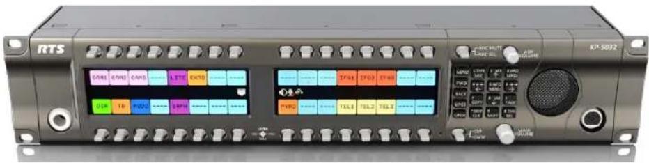
| Product Type | Intercom Keypanel (Lever Key or Pushbutton) |
| Model | RTS KP-5032 / KP-5032PB |
| Display | High-resolution wide-angle TFT LCD, 576 x 172 pixels, 16-bit color (64K RGB) |
| Dimensions (W x H x D) | 17.39 in x 3.46 in x 3.88 in (441.82 mm x 87.96 mm x 98.5 mm) including knobs |
| Weight | 4.89 lb (2.22 kg) |
| Power Supply | External DC supply, AC input 100-240 VAC 50/60 Hz |
| Power Consumption | 13 W nominal, 18 W maximum (48 VA max) |
| Audio Technology | OMNEO (Dante audio over IP) with 1 ms latency |
| Audio Inputs | Matrix (balanced), Aux 1 & 2 (balanced), Front Panel Mic (electret), Rear Panel Mic (electret), Headset Mic (electret/dynamic) |
| Audio Outputs | Matrix (balanced), Line Out/Mic Out (balanced), Front/Rear Headset, Rear Speaker (5W @ 8Ω), Front Speaker (84 dB SPL @ 1m) |
| GPIO | 2 opto-isolated inputs (5-18 VDC), 2 SPDT relay outputs (1A @ 30VDC) |
| Network Connectivity | Dual RJ-45 Ethernet (100/1000 Mbps), optional SFP fiber, RJ-12/RJ-45 Frame connector (568B/USOC) |
| Headset Connector | Front and rear, field-swappable between 4-pin, 5-pin, or 6-pin XLR |
| Microphone Connector | Front and rear panel mic (MCP5/MCP6/MCP90 series), screw-lock |
| Firmware Upgrade | Via AZedit, IPedit, or Firmware Upload Tool; supports bootloader updates |
| Optional Packages | Audio Package (voice messaging, AFK), Control Package (keypanel mirroring, real-time control) |
| Glitch-Free Operation | Supports primary/secondary Ethernet redundancy (requires compatible hardware and software) |
| Operating Temperature | 0°C to 55°C (32°F to 131°F) |
| Storage Temperature | -20°C to 70°C (-4°F to 158°F) |
| Certifications | CE, FCC Part 15 Class A, UL 60950-1, EN 55022/55024, VCCI, ICES-003, etc. |
Frequently Asked Questions - KP-5032 RTS
User questions about KP-5032 RTS
0 question about this device. Answer the ones you know or ask your own.
Ask a new question about this device
Download the instructions for your Audio mixer in PDF format for free! Find your manual KP-5032 - RTS and take your electronic device back in hand. On this page are published all the documents necessary for the use of your device. KP-5032 by RTS.
USER MANUAL KP-5032 RTS
Lever Key and Pushbutton Versions
up to and including version 2.1.1
includes support for
Control Package and Audio Package



PROPRIETARY NOTICE
The product information and design disclosed herein were originated by and are the property of Bosch Security Systems, Inc. Bosch reserves all patent, proprietary design, manufacturing, reproduction, use and sales rights thereto, and to any article disclosed therein, except to the extent rights are expressly granted to others.
COPYRIGHT NOTICE
Copyright 2017 by Bosch Security Systems, Inc. All rights reserved. Reproduction, in whole or in part, without prior written permission from Bosch is prohibited.
*All other trademarks are property of their respective owners.
WARRANTY AND SERVICE INFORMATION
For warranty and service information, refer to the appropriate web site below:
RTS Intercoms ...... www.rtsintercoms.com/warranty
RTS Digital
RTSTW
AudioCom
RadioCom
Intercom Headsets
CUSTOMER SUPPORT
Technical questions should be directed to:
Customer Service Department
Bosch Security Systems, Inc.
www.rtsintercoms.com
TECHNICAL QUESTIONS
Bosch Security Systems Technical Support
http://www.rtsintercoms.com/contact_main.php
DISCLAIMER
The manufacturer of the equipment described herein makes no expressed or implied warranty with respect to anything contained in this manual and shall not be held liable for any implied warranties of fitness for a particular application or for any indirect, special, or consequential damages. The information contained herein is subject to change without prior notice and shall not be construed as an expressed or implied commitment on the part of the manufacturer.
|  THE LIGHTNING FLASH AND ARROWHEAD WITHIN THE TRIANGLE IS A WARNING SIGN ALERTING YOU OF "DANGEROUS VOLTAGE" INSIDE THE PRODUCT. | CAUTION RISK OF ELECTRIC SHOCK DO NOT OPEN CAUTION: TO REDUCE THE RISK OF ELECTRIC SHOCK, DO NOT REMOVE COVER. NO USER-SERVICEABLE PARTS INSIDE. REFER SERVICING TO QUALIFIED SERVICE PERSONNEL. |  THE EXCLAMATION POINT WITHIN THE TRIANGLE IS A WARNING SIGN ALERTING YOU OF IMPORTANT INSTRUCTIONS ACCOMPANYING THE PRODUCT. |
| SEE MARKING ON BOTTOM/BACK OF PRODUCT. | ||
WARNING: APPARATUS SHALL NOT BE EXPOSED TO DRIPPING OR SPLASHING AND NO OBJECTS FILLED WITH LIQUIDS, SUCH AS VASES, SHALL BE PLACED ON THE APPARATUS.
WARNING: THE MAIN POWER PLUG MUST REMAIN READILY OPER-ABLE.
CAUTION: TO REDUCE THE RISK OF ELECTRIC SHOCK, GROUNDING OF THE CENTER PIN OF THIS PLUG MUST BE MAINTAINED.
WARNING: TO REDUCE THE RISK OF FIRE OR ELECTRIC SHOCK, DO NOT EXPOSE THIS APPARATUS TO RAIN OR MOISTURE.
WARNING: TO PREVENT INJURY, THIS APPARATUS MUST BE SECURELY ATTACHED TO THE FLOOR/WALL/RACK IN ACCORDANCE WITH THE INSTALLATION INSTRUCTIONS.
| ~ | This product is AC only. |
| CE |
WARNING: THIS IS A CLASS A PRODUCT. IN A DOMESTIC ENVIRONMENT THIS PRODUCT MAY CAUSE RADIO INTERFERENCE, IN WHICH CASE THE USER MAY BE REQUIRED TO TAKE ADEQUATE MEASURES.
Important Safety Instructions
- Read these instructions.
- Keep these instructions.
- Heed all warnings.
- Follow all instructions.
- Do not use this apparatus near water.
-
Clean only with dry cloth.
-
Do not block any ventilation openings. Install in accordance with the manufacturer's instructions.
-
Do not install near any heat sources such as radiators, heat registers, stoves, or other apparatus (including amplifiers) that produce heat.
-
Do not defeat the safety purpose of the polarized or grounding-type plug. A polarized plug has two blades with one wider than the other. A grounding type plug has two blades and a third grounding prong. The wide blade or the third prong are provided for your safety. If the provided plug does not fit into your outlet, consult an electrician for replacement of the obsolete outlet.
-
Protect the power cord from being walked on or pinched particularly at plugs, convenience receptacles, and the point where they exit from the apparatus.
-
Only use attachments/accessories specified by the manufacturer.
-
Use only with the cart, stand, tripod, bracket, or table specified by the manufacturer, or sold with the apparatus. When a cart is used, use caution when moving the cart/apparatus combination to avoid injury from tip-over.
-
Unplug this apparatus during lightning storms or when unused for long periods of time.
-
Refer all servicing to qualified service personnel. Servicing is required when the apparatus has been damaged in any way, such as power-supply cord or plug is damaged, liquid has been spilled or objects have fallen into the apparatus, the apparatus has been exposed to rain or moisture, does not operate normally, or has been dropped.
Table
of
Contents
INTRODUCTION 13
Features 13
Specifications 14
KP-4016/5032 Block Diagram 16
Reference View - KP-5032 17
Reference View - KP-4016 18
Connector Pinouts ....19
INSTALLATION 21
Requirements 21
KP-5032/5032PB Installation 22
KP-4016/4016PB Installation 23
Connecting the Keypanel to the Intercom ....24
Power Up 27
Address Setting 28
Connections 29
Footswitch Cabling 36
BASIC OPERATION 37
Intercom Keys and Displays ....37
Keypad Reference View 41
INFO button 46
Breadcrumb Menu Navigation ....47
Menu Navigation and Shaft Encoder Knobs 47
CLR Button 48
Basic Key Operation 48
Key Gain Adjustment ....50
Keypanel Volume Adjustments ....52
Aux Volume Adjustments ....54
Priority Call Volume Control ....56
Operation of Intercom Keys with Auto Functions ....58
Operation of Intercom Keys with Options 59
Operation of Intercom Talk Keys with the Speaker DIM Setting 59
Operation of Intercom Keys assigned to TIF Ports 60
User Quick Select Scrolling 60
6 KP Series
Graphical Call Waiting Window ....61
Mute the Microphone 64
Mic Select 65
Setup Pages 67
Menu Passwords 68
Voice Messaging (Audio Package Only) 68
User Programmable Buttons 73
Keypanel Color Window 75
Enhanced Tallies 83
Flash Text Characteristics Window 87
Show Icon Characteristics Window 89
Panel Tally 93
Create and Download New Icons 94
Keypanel Mirroring (Control Package Only) 96
Real-Time Control in AZedit (Control Package Only) 99
Keypanel Configuration (Control Package Only) 109
FIRMWARE DOWNLOAD 161
Download Firmware to the Keypanel From AZedit 161
Download Firmware to the Keypanel Using the Firmware Upload Tool ....163
Enable Downloading New Bootloader from the Keypanel 166
Download Firmware Using the Bootloader 166
Display the FPGA Version on the Keypanel 169
Download and Upgrade the FPGA to the KP-5032/4016 169
Download a Splash Screen 173
Download a Font File ....175
Download an Icon File ....177
Download User Chimes (Control Package Only) 179
Download Screen Savers (Control Package Only) 181
KP-4016/5032 MENU SYSTEM 185
Main Menu Access ....185
Menu System, Audio Options ....186
Menu System, Display 214
Menu System, Key Assign Menu ....218
Menu System, Key Options Menu ....223
Menu System, OMNEO Offers 235
Menu System, RVON Offers (Only available when an RVON-IO is detected) 236
Menu System, Save Config 236
Menu System, Service ....237
TELEPHONE INTERFACE (TIF) OPERATION 259
Receiving A Phone Call 259
Dialing and Hanging Up 259
Centralized Auto Dials 261
KEYPAD QUICK REFERENCE 265
Keypad Sequence Introduction ....265
KEYPANEL MENU QUICK REFERENCE 269
Audio Options 269
Display Menu 277
Key Assign Menu 278
Key Options Menu 279
OMNEO Offers Menu 282
Save Config Menu 282
Service Menu 283
EKP-4016 287
Introduction 287
Specifications 287
EKP-4016 Expansion Panel Reference View 289
Expansion Panel Cabling Reference 290
Unicode Support 293
AZedit and Unicode Support 293
Power Supply Mounting Options 297
Power Supply Mounting Bracket Instructions ....297
Audio and Control Packages 303
Audio and Control Add-On Package 303
Download License Files ....304
ST-2110-30 for RTS OMNEO Devices 307
Prerequisites 307
Operation 307
Set up a ST-2110-30 Transmit (Rx) Audio Flow 311
IPedit Operations 313
Glitch-Free Operation - ST2022-7 317
Overview 317
Minimum Software Versions 317
Features 317
Install Glitch-Free Devices 318
Configure Glitch-Free Devices ....320
List
of
Figures
FIGURE 1. KP-4016/5032 Audio Flow Block Diagram 16
FIGURE 2. KP-5032 Reference View (pushbutton version shown on top) 17
FIGURE 3. KP-4016 Reference View (pushbutton version shown on top) 18
FIGURE 4. KP-5032 Installation 22
FIGURE 5. KP-4016/4016BP Installation 23
FIGURE 6. Female Headset Connector Set Screw Access Hole 30
FIGURE 7. Male Headset Connector Set Screw Access Hole 30
FIGURE 8. Footswitch Cable Drawing 36
FIGURE 9. KP-5032, KP-5032PB, KP-4016, and KP-4016PB Keypad 41
FIGURE 10. Breadcrumbs Navigation 47
FIGURE 11. Key Function Position Explanation 48
FIGURE 12. Pushbutton Key Function Explanation 49
FIGURE 13. Talk/Listen Indicators 50
FIGURE 14. Incoming Priority Call Volume Control Keypanel 56
FIGURE 15. Graphical Call Waiting Window/ KP-5032 ...... 61
FIGURE 16. Graphical Call Waiting Window/ KP-4016 ...... 61
FIGURE 17. Graphical Call Waiting Window Highlighted Call 62
FIGURE 18. KP-4016 Mic MUTE and Mic SEL 64
FIGURE 19. VM Button 71
FIGURE 20. Voice Message Menu 71
FIGURE 21. VM Playback Menu 72
FIGURE 22. Keypanel Colors Window 75
FIGURE 23. Color Grid 77
FIGURE 24. Key Assignments Page 78
FIGURE 25. Assignments Groups Page 80
FIGURE 26. Miscellaneous Colors Page 82
FIGURE 27. Enhanced Tallies Window 83
FIGURE 28. Flash Text Characteristics Window 87
FIGURE 29. Show Icon Characteristic Window 89
FIGURE 30. 512 x 64 pixel bitmap of key overlay icons 94
FIGURE 31. 512 x 128 pixel bitmap of panel icons 95
FIGURE 32. Real Time Warning Message 101
FIGURE 33. When Ganged Volumes are Configured 104
FIGURE 34. Keypanel Configuration – Panel Options ....111
FIGURE 35. Panel Options Page – Panel Swap Group Box 113
FIGURE 36. Panel Options Page – UPG Key Definition Group Box 114
FIGURE 37. Panel Options Page – Quick-Assign Listen Assignments Group Box ...... 115
FIGURE 38. Panel Options Page – Panel Mode Group Box 115
FIGURE 39. Panel Options Page – Miscellaneous Group Box 116
FIGURE 40. Panel Options Page – Snoop Tally Group Box 116
FIGURE 41. Panel Options Page – GPI Input Assignments Group Box 117
FIGURE 42. Panel Options Page – GPI Output Assignments Group Box 117
FIGURE 43. Panel Options Page – Footswitch Mode Group Box 118
FIGURE 44. Keypanel Configuration – Display Page 119
FIGURE 45. Display Page – Keypad Backlight Group Box 120
FIGURE 46. Display Page – Key Display Options Group Box 120
FIGURE 47. Display Page – Panel Display Options Group Box 121
FIGURE 48. Display Page – LCD Backlight Group Box 122
FIGURE 49. Display Page – Screen Saver Group Box 122
FIGURE 50. Keypanel Configuration – Key Options Page 123
FIGURE 51. Key Options Page – Solo and Exclusive Keys Group Box 124
FIGURE 52. Key Options Page–Latch Disable Group Box 125
FIGURE 53. Key Options Page – Button Lock Group Box 126
FIGURE 54. Key Options Page – Tallies Group Box 127
FIGURE 55. Key Options Page – Autodial Numbers Group Box 128
FIGURE 56. Key Options Page – One-Touch Autodials Group Box 129
FIGURE 57. Key Options Page – Key Groups Group Box 130
FIGURE 58. Key Options Page – Chimes Group Box ...... 131
FIGURE 59. Key Options Page – Key Icons Group Box 132
FIGURE 60. Key Options Page – Key Volumes Group Box ...... 133
FIGURE 61. Keypanel Configuration – Audio Options 134
FIGURE 62. Audio Options Page – Mic Modes Group Box 135
FIGURE 63. Audio Options Page – Speaker / Headset Modes Group Box 135
FIGURE 64. Audio Options Page – Aux Inputs Group Box ...... 136
FIGURE 65. Audio Options Page – Mic Options Group Box 138
FIGURE 66. Audio Options Page – Matrix Out and Sidetone Options Group Box ...... 139
FIGURE 67. Audio Options Page – Headset Configuration Group Box 140
FIGURE 68. Audio Options Page – Ganged Volumes Group Box 140
FIGURE 69. Audio Options Page – Tone Generator Group Box 141
FIGURE 70. Audio Options Page – VM Options Group Box 141
FIGURE 71. Keypanel Configuration – Audio Levels 142
FIGURE 72. Audio Levels Page – Input Volumes Group Box 143
FIGURE 73. Audio Levels Page – Output Volumes Group Box 144
FIGURE 74. Audio Levels Page – Minimum Output Volumes Group Box ...... 144
FIGURE 75. Audio Levels Page – Output Dim Amounts Group Box ...... 145
FIGURE 76. Audio Levels Page – Minimum Input Volumes ..... 145
FIGURE 77. Audio Levels Page – Maximum Output Volumes Group Box 146
FIGURE 78. Audio Levels Page – Chime Volumes Group Box 147
FIGURE 79. Keypanel Configuration – Advanced 148
FIGURE 80. Advanced Page – AGC Group Box 149
FIGURE 81. Advanced Page – Mixing Group Box 150
FIGURE 82. Advanced Page – Compression Group Box 151
FIGURE 83. Advanced Page – Gating Group Box 152
FIGURE 84. Advanced Page – Noise Gate Group Box 153
FIGURE 85. Keypanel Configuration – Filters Page 154
FIGURE 86. Filters Page – Input Bandpass Filters Group Box ...... 155
KP Series 11
FIGURE 87. Filters Page – Output Bandpass Filters Group Box ....156
FIGURE 88. Filters Page – Input Equalization Filters Group Box ......157
FIGURE 89. Filters Page – Output Equalization Filters Group Box ....158
FIGURE 90. Filters Page – Notch Filter Mode Selection .....159
FIGURE 91. Automatic Gain Control Example .....188
FIGURE 92. EKP-4016 Expansion Panel Reference View – Front and Rear (EKP-4016PB shown in inset) ......289
FIGURE 93. Expansion Panel Cabling ......290
FIGURE 94. Mounting Bracket – Horizontal on a Crossbar ....301
FIGURE 95. Mounting Bracket – Vertical from a Crossbar ....301
FIGURE 96. Glitch-Free System Diagram ....318
FIGURE 97. Primary and Secondary OMNEO connector positions ....319
The KP-4016/5032 series keypanels deliver superior high-quality digital audio using OMNEO technology from Bosch with Dante audio over IP via either copper or fiber. The KP-4016/5032 series keypanels delivers audio, free of noise, delay, and other artifacts present in legacy technology. This family of keypanels includes a rich set of connectors as standard, including GPIO (General Purpose Input and Output) and RC (Rear Connector) kit. As with other RTS products, emphasis is placed on backward compatibility with previous generations of matrices including analog technology.
The KP-4016/5032 series utilizes the latest generation of wide angle TFT displays providing superior clarity, resolution, and longer display life delivering high-quality readability under a variety of lighting conditions.
Optionally, there are two packages (control and audio) with additional features and functions, such as voice message, real-time control, keypanel mirroring, etc. For more information on these packages, see “Audio and Control Packages” on page 303.
Features
- Superior digital, high-quality audio over IP (Internet Protocol) included through OMNEO technology, the branded IP-based solution from Bosch.
- Advanced signal processing, delivering an audio experience, free of noise, echo, delay and other artifacts present in legacy technology.
- Backward compatible with legacy technologies, such as analog audio in USOC and 568-B formats.
- All previous optional hardware connectors (RC, GPI, etc) are now standard.
- New wide-angle high-definition display.
• Enhanced keypanel menus optimized for case of use. - Front panel headset connector is field-swappable, making it simple to change the default 6-pin XLR headset connector with either a 5-pin XLR or 4-pin XLR headset connector without opening the unit, as needed.
- For an additional price each, an Audio and/or Control add-on package is available for the KP-4016/5032, to greatly expand your keypanel and intercom system experience and capabilities. For more information on these packages, see “Audio and Control Packages” on page 303.
Specifications
LCD Display
KP-4016:
Active Area.... 120.10 mm (wide) x 18.77 mm (high)
Dot Resolution....576 x 90 pixels
Color Resolution ....16-bit (64 K) RGB color
View Angle....80 degrees (typical; all directions)
KP-5032
Active Area ...... 120.10 mm (wide) x 35.86 mm (high)
Dot Resolution....576 x 172 pixels
Color Resolution ......16-bit (64 K) RGB color
View Angle.... 80 degrees (typical; all directions)
Power Supply:
Type: External DC
AC Input: 100–240 VAC 50/60 Hz
General Purpose Inputs and Outputs:
Outputs
Type (relays) SPDT
Contact Rating....1 AMP @ 30 VDC
Inputs
Type....Optically Coupled
Input Voltage 5-18 VDC on A+
◆A+ is internally pulled to 5VDC. Connect K- to to activate.
Inputs:
Matrix
Type...... Balanced
Typical Input Level ....+8 dBu
Typical Input Impedance ....>10 kΩ
Maximum Input Level....+20 dBu
Supported Bandwidth....100 Hz to 20 kHz
Aux 1 and Aux 2
Type...... Balanced
Typical Input Level ....+8 dBu
Typical Input Impedance ....>10 kΩ
Front Panel Mic
Type .... Electret
Typical Input Level....-42 dBu
Typical Input Impedance ....1 kΩ
Maximum Input Level ......-25 dBu
Rear Panel Mic
Type .... Electret
Typical Input Level....-42 dBu
Typical Input Impedance ....1 kΩ
Maximum Input Level ......-25 dBu
Front and Rear Headset Mic - Electret
Typical Input Level....-42 dBu
Typical Input Impedance ....1 kΩ
Maximum Input Level ......-25 dBu
Front and Rear Headset Mic - Dynamic
Typical Input Level....-50 dBu
Typical Input Impedance 600 Ω
Maximum Input Level ......-25 dBu
Outputs:
Matrix
Type ....Balanced
Typical Output Level ....+8 dBu
THD + N% <0.20%
Typical Output Impedance....600 Ω
Maximum Output Level ....+20 dBu
Frequency Response 100 Hz to 20 kHz
MIC/LINE Out
Type ....Balanced
Typical Output Level ....+8 dBu
THD + N% <0.20%
Typical Output Impedance....600 Ω
Maximum Output Level ....+20 dBu
Frequency Response 100 Hz to 20 kHz
Headset - Front, Rear
Maximum
Output Power ....125 mW for 32 Ω load
Earphone Impedance....16 Ω and above
THD+N% ....<0.20%
Frequency Response....100 Hz to 20 kHz
Speaker - Rear
Maximum Output Power.... 5 W for 8 Ω load
Speaker Impedance 4 Ω and 8 Ω
THD+N% ....<0.20%
Frequency Response....100 Hz to 20 kHz
Speaker - Front
SPL....84 dBSPL for 1 kHz sine wave @ 1 meter
Digital:
OMNEO Channels
Typical OMNEO Latency ....1ms
Frequency Response....20Hz - 20kHz
Environmental:
Dimensions
KP-4016
17.39" W (without rack ears) x 1.72" H x 3.88" D
(441.82 mm x 43.8 mm x 98.5 mm
[111.11 mm including volume knobs and lever keys])
KP-5032
17.39" W (without rack ears) x 3.46" H x 3.88" D
(441.82 mm x 87.96 mm x 98.5 mm
[111.11 mm including volume knobs and lever keys])
Weight
KP-4016 3.5 lb. (1.58 kg)
KP-5032 4.89 lb (2.22 kg)
Power Supply 0.53 lb (0.24 kg)
Power Supply
Mounting Bracket.... 0.30 lb (0.14 kg)
Temperature
Operating.... 0° C to 55° C (32° F to 131° F)
Storage....-20°C to 70°C (-4°F to 158°F)
Power Consumption:
KP-4016
Nominal 12 Watts
Maximum 15 Watts
Maximum Volt Amp ....48 VA
KP-5032
Nominal 13 Watts
Maximum 18 Watts
Maximum Volt Amp ....48 VA
Certification:
CE Compliance
EMC
• EN 55022 Class A
• VCCI Class A
ICES-003 Class A
• FCC Part 15 Subpart B Class A
• AS/NZS CISPR22 Class A
- Korean KN 22 Class A
- BSMI Class A
EN 55024
- Korean KN 24
Safety
- UL 60950-1
• EN 60950-1
CB Report
• PSE
KP-4016/5032 Block Diagram

flowchart
graph LR
    subgraph OMNEO1 &2
        OMNEO1["OMNEO 1 & 2 Connection"] --> OMNEO2["OMNEO 2"]
        OMNEO2 --> OMNEO1["OMNEO 1"]
        OMNEO1 --> DigitalMatrixIn["Digital Matrix In (OMNEO 1)"]
        DigitalMatrixIn --> AnalogMatrixIn["Analog Matrix In"]
        AnalogMatrixIn --> MatrixIn["Matrix In"]
    end

    subgraph FrontMicrophoneJack
        FrontMicrophoneJack["Aux 1"] --> Aux1["Aux 1"]
        Aux1 --> Aux2["Aux 2"]
        Aux2 --> FrontPanelMic["Front Panel Mic"]
        FrontPanelMic --> RearPanelMic["Rear Panel Mic"]
        RearPanelMic --> FrontHeadsetMic["Front Headset Mic"]
        RearHeadsetMic --> RearHeadsetMic["Rear Headset Mic"]
    end

    subgraph RearMicrophoneConnector
        RearMicrophoneConnector["Aux 2"] --> FrontMicrophoneJack
        RearMicrophoneConnector["Aux 3"] --> FrontHeadsetConnector["Front Headset Connector"]
        RearMicrophoneConnector["Aux 4"] --> RearHeadsetConnector["Rear Headset Connector"]
    end

    subgraph RearHeadsetConnector
        RearHeadsetConnector["Aux 5"] --> RearHeadsetConnector["Rear Headset Connector"]
    end

    subgraph LineOut/MicOut
        LineOut/MicOut["Line Out/Mic Out"] --> OutputLevelGain["Output LevelGain"]
        OutputLevelGain --> FrontSpeaker["Front Speaker"]
        OutputLevelGain --> RearSpeaker["Rear Speaker"]
        RearSpeaker --> FrontLeftHeadset["Front Left Headset"]
        RearSpeaker --> FrontRightHeadset["Front Right Headset"]
        RearLeftHeadset["Front Left Headset"]
        RearRightHeadset["Front Right Headset"]
    end

    OMNEO2["OMNEO 2"] --> Mixer["Mixer"]
    OMNEO1["OMNEO 1"] --> Mixer
    MatrixOut["Matrix Out"] --> Mixer
    LineOut/MicOut --> Mixer
FIGURE 1. KP-4016/5032 Audio Flow Block Diagram
Reference View - KP-5032

FIGURE 2. KP-5032 Reference View (pushbutton version shown on top)
- Multi-Directional Lever Keys (pushbuttons on KP5032PB)
- High Resolution, Wide-Angle LCD Display
- MIC MUTE/MIC SEL Lever Key
- AUX VOLUME Knob/Menu Navigation
- Keypad
- Main Speaker (Front)
- Microphone Connector
- CLR/CWW Lever Key
- MAIN VOLUME Knob
- Headset Connector (Front Panel)
- Power Supply Bracket Mounting Holes
- Power Supply Cable Tie Mounting Hole
- POWER Connector
- SPEAKER Rear Connector (2-position Terminal Block)
- AUX 1 Connector
-
AUX 2 Connector
-
HEADSET Connector (Rear Panel)
-
EXT MIC Connector
-
LINE OUT/MIC OUT Connector
-
FRAME Connector
-
EXP/LCP Connector
-
GPIO Connector (12-position Terminal Block)
-
OMNEO ETHERNET Connector (See "Ethernet Connector" on page 29)
-
OMNEO ETHERNET Connector (See "Ethernet Connector" on page 29)
-
OMNEO OPTICAL (fiber) Connector SM SFP Module (F.01U.278.502) MM SFP Module (F.01U.278.503)
-
OMNEO OPTICAL DETECT (fiber) Indicator LED
Reference View - KP-4016

FIGURE 3. KP-4016 Reference View (pushbutton version shown on top)
- Microphone Connector
- High Resolution, Wide-Angle LCD Display
- Keypad
- AUX VOL. Knob
- Main Speaker (Front)
- Headset Connector (Front Panel)
- Multi-Directional Lever Keys (pushbutton keys on KP-4016PB)
- MAIN VOL. Knob
- POWER Connector
- SPEAKER Rear Connector (2-position Terminal Block)
- RJ-45 FRAME Connector
- RJ-45 EXP/LCP Connector
- OMNEO ETHERNET Connector (See "Ethernet Connector" on page 29)
- OMNEO OPTICAL (fiber) Connector SM SFP Module (F.01U.278.502) MM SFP Module (F.01U.278.503)
- OMNEO OPTICAL (fiber) Indicator LED
- AUX 1 Connector
- AUX 2 Connector
- HEADSET Connector (Rear Panel)
- EXT MIC Connector
- LINE OUT/MIC OUT Connector
- GPIO Connector (12-position Terminal Block)
Connector Pinouts
| Power Supply: J1 | |
| Pin Assignment | |
| Pin 1 24 VDC | |
| Pin 2 GND | |
| Pin 3 Chassis GND | |
| Rear Panel Mic: J6 | |
| Pin Assignment | |
| 1 REAR PANEL MIC IN - | |
| 2 | REAR PANEL MIC IN + |
| 3 GND | |
| Rear Speaker: J2 | |
| Pin Assignment | |
| Pin 1 Rear Speaker - | |
| Pin 2 Rear Speaker + | |
| MIC OUT/LINE OUT: J7 | |
| Pin Assignment | |
| 1 GND | |
| 2 MIC_OUT/LINE_OUT + | |
| 3 MIC_OUT/LINE_OUT - | |
| Aux 1: J3 | |
| Pin Assignment | |
| Pin 1 GND | |
| Pin 2 AUX 1 IN | + |
| Pin 3 AUX 1 IN | - |
| Matrix Connector: J8 ^a | ||
| Pin RJ-45 RJ-12 | ||
| 1 RS485 - | ||
| 2 RS485 - RS485 - | ||
| 3 FROM MATRIX + | FROM MATRIX + | |
| 4 TO MATRIX + | TO MATRIX + | |
| 5 TO MATRIX - | TO MATRIX - | |
| 6 FROM MATRIX - | FROM MATRIX - | |
| 7 RS485 + | RS485 + | |
| 8 RS485- | ||
| AUX 2: J4 | |
| Pin Assignment | |
| 1 | GND |
| 2 | AUX 2 IN + |
| 3 | AUX 2 IN - |
a. Supports 568B and USOC wiring
| Rear Headset: J5 | |
| Pin Assignment | |
| 1 REAR_HS_MIC_IN - | |
| 2 REAR_HS_MIC_IN + | |
| 3 REAR_HS_COMMON | |
| 4 REAR_HS_L_OUT | |
| 5 REAR_HS_R_OUT | |
| EXP/LCP Connector: J9 | |
| Pin Assignment | |
| 1 LCP_DATA_STROBE | |
| 2 LCP_DATA_CLK | |
| 3 LCP_DATA_IN | |
| 4 GND | |
| 5 GND | |
| 6 | |
| 7 RS485 + | |
| 8 RS485 - | |
| ETHERNET: J12 | |
| Pin | Assignment |
| 1 | Data 1 + |
| 2 | Data 1 - |
| 3 | Data 2 + |
| 4 | Data 3 + |
| 5 | Data 3 - |
| 6 | Data 2- |
| 7 | Data 4+ |
| 8 | Data 4- |
| GPIO Connector: J10 | ||
| Pin Assignment Silk Screen | ||
| Opto-2/Relay-2 | ||
| 1 Chassis GND | ||
| 2 OPTO2 CATHODE K- | ||
| 3 OPTO2 ANODE A+ | ||
| 4 RELAY2_NO NO | ||
| 5 RELAY2_NC NC | ||
| 6 RELAY2_COM C | ||
| Opto-1/Relay-1 | ||
| 7 Chassis GND | ||
| 8 OPTO1 CATHODE K- | ||
| 9 OPTO1 ANODE A+ | ||
| 10 RELAY1_NO NO | ||
| 11 RELAY1_NC NC | ||
| 12 RELAY1_COM C | ||
| ETHERNET: J11 | |
| Pin | Assignment |
| 1 | Data 1 + |
| 2 | Data 1 - |
| 3 | Data 2 + |
| 4 | Data 3 + |
| 5 | Data 3 - |
| 6 | Data 2- |
| 7 | Data 4+ |
| 8 | Data 4- |
| Front Panel Mic | |
| Pin | Assignment |
| Tip | REAR_PANEL_MIC_IN + |
| Ring | REAR_PANEL_MIC_IN - |
| Sleeve | CGND |
| Front Headset | |||
| Pin | Assignment | ||
| 4-Pin | 5-Pin | 6-Pin | |
| 1 | FRONT_HS_MIC_IN- | FRONT_HS_MIC_IN- | FRONT_HS_MIC_IN- |
| 2 | FRONT_HS_MIC_IN+ | FRONT_HS_MIC_IN+ | FRONT_HS_MIC_IN+ |
| 3 | FRONT_HS_COMMON | FRONT_IIS_COMMON | FRONT_IIS_COMMON |
| 4 | FRONT_HS_L_OUT | FRONT_HS_L_OUT | FRONT_HS_L_OUT |
| 5 | FRONT_HS_R_OUT | FRONT_HS_R_OUT | |
| 6 | No Connect | ||
Requirements
The following keypanel firmware versions are needed for the specified KP-4016/5032 model:
AZedit...... V5.2.0 or later
IPedit...... V3.2.3 or later
MCII-e...... V3.4.0 or later
AIO-16...... V1.7.0 or later
FWUT...... V4.20.3586 or later
DNS-SD...... V4.20.3586 or later
OMI ...... V5.2.12 or later for lever key model
V.6.1.8 or later for pushbutton model
KP-5032/5032PB Installation
IMPORTANT:
If you plan to use the Power Supply Mounting Bracket, we recommend you install the mounting bracket before cabling the keypanel. For information on different power supply mounting options, see “Power Supply Mounting Options” on page 297.

FIGURE 4. KP-5032 Installation
IMPORTANT:
When an OEI-2 power supply is used on a KP-Series keypanel, the following warning icon blinks to display the wrong power supply is being used. No damage occurs.

To install the KP-5032/5032PB, do the following:
- On the rear panel, plug the 24 VDC power connector (A) of the power supply into the power connector on the back panel of the unit.
- Connect an RJ-12 or RJ-45 (568B or USOC) cable (B) with RTS cabling to the J8 FRAME connector. OR
Connect a CAT-5e cable (C) to either J11 or J12 ETHERNET connector.
NOTE:
- If using the optional J13 fiber connector, connect a fiber connector (D) to the OPTICAL fiber connector on the rear panel.
-
The KP-Series panels can have both AIO and Ethernet connected simultaneously, an the user can switch between the connections using the menus.
-
Once the unit is cabled, plug the power supply power cord into the wall outlet or a power strip.
KP-4016/4016PB Installation
IMPORTANT:
For information on different power supply mounting options, see "Power Supply Mounting Options" on page 297.

FIGURE 5. KP-4016/4016BP Installation
To install the KP-4016, do the following:
- On the rear panel, plug the 24VDC power connector (A) of the power supply into the power connector on the back panel of the unit.
- Connect an RJ-12 or RJ-45 (568B or USOC) cable (B) with RTS cabling to the J8 FRAME connector on the rear panel.
OR
Connect a CAT-5e cable (C) to either J11 or J12 ETHERNET connector on the rear panel.
NOTE:
- If using the optional J13 fiber connector, connect a fiber connector (D) to the OPTICAL fiber connector on the rear panel.
-
The KP-Series panels can have both AIO and Ethernet connected simultaneously, an the user can switch between the connections using the menus.
-
Once the unit is cabled, plug the power supply power cord into the wall outlet or a power strip.
Connecting the Keypanel to the Intercom
You can configure the OMI using AZedit and IPedit; however, only IPedit can be used to configure the keypanel.
Naming Devices in IPedit
IMPORTANT:
If you change the device name, this causes the device to reboot. It is not necessary to change the device name. However, if you do change the name, it is best to do this early in the setup so you do not have to revisit other devices that connect to this device and update them later.
To name either an OMI care or an OKP, do the following:
In the Device Name field, enter a device name familiar to you. Initially, devices are given a default name.
Naming the OMI in AZedit
NOTE: Only the OMI card can be renamed and configured from both AZedit or IPedit.
To name the OMI, do the following:
-
In AZedit, from the Status menu, select I/O Cards. The I/O Cards window appears.
-
Right-click the desired OMI card. A popup menu appears.
-
From the popup menu, select OMNEO Configuration. The OMNEO Configuration window appears.
-
In the Device Name field, enter an OMI name familiar to you. Initially, OMI cards are given a default name.
-
Click Apply. The OMNEO Configuration window closes.
Configure the OMI using AZedit
To configure the OMI to connect to the KP-Series panels, do the following:
-
From the Status menu in AZedit, select I/O Cards. The I/O Card Status window appears showing a list of installed cards.
-
Right-click the OMI card you want to configure. A pop-up menu appears.
-
From the pop-up menu, select OMNEO Configuration. The OMNEO Configuration window appears.
-
From the OMNEO card drop down menu, select the slot number where the OMI card is located in the frame. The Device Name field auto-populates with the name of the device.
-
From the Local Channel drop down menu, select the channel you want to use to communicate to your keypanel across the network.
NOTE: Channels not already configured to connect to another device appear with an asterisk (*) next to them.
- In the Partner Device Name field, enter the name of keypanel you want to use to communicate with or select the Browse icon to select from a list of devices.
The Partner IP Address field auto-populates when you select the Device Name. - From the Partner Device Type drop down menu, select the type of device to which the OMI card is connecting.
- From the Partner Channel drop down menu, select the channel on the device to which the OMI communicates.
- Once you are finished, click Apply.
Apply sends all the changes to all the cards in the intercom.
OR
Click Cancel to discard all the changes made.
Add the OMI to the Device Catalog in IPedit
To add the OMI to IPedit, do the following:
- Open IPedit.
- From the Device menu, select Add.
The Add Devices Window appears, open to the Search tab. - Select the OMI card.
The Add button becomes active. - Click the Add button.
The OMI card appears in the device catalog in the left panel. - Click the Done button.
The Add Devices window closes.
Configure the OMI using IPedit
To configure the OMI using IPedit, do the following:
Using the Device Configuration and Status Panc
- In the Description field, enter a description for the OMI card, if desired.
Using the Channel Configuration and Status Section:
-
In the Channel Description field, enter a channel description, if applicable.
-
From the Destination Type drop down menu, select OKP.
NOTE: The Destination Type does not need to be selected if using the Browse window to select the device. It fills the type and IP Address automatically. The type is either OKP-2 or OKP-8 depending on whether keypanel is licensed for 2 or 8 channels.
- In the Destination Device Name field, enter the name of the device to which the channel will connect. OR
Click the ... button.
The Discovered Devices Window appears.
a. Expand the tree to view the destination devices available.
b. From the expanded tree, select the device you want for your destination device.
c. Click OK.
-
From the Destination Channel drop down menu, select the channel to which the OMI will connect.
-
Send the changes to the OMI.
Add the KP-Series Keypanels to the Device Catalog in IPedit
To add the keypanel to IPedit, do the following:
- Open IPedit.
- From the Device menu, select Add.
The Add Devices Window appears, open to the Search tab. - Select the keypanel.
The Add button becomes active. - Click the Add button.
The OKP-2/8 appears in the device catalog in the left panel. - Click the Done button.
The Add Devices window closes.
Configure the KP-Series Panels using IPedit
To configure the keypanel using IPedit, do the following:
Using the Device Configuration and Status Pane
- In the Description field, enter a description for the keypanel, if desired.
Using the Channel Configuration and Status Section:
-
In the Channel Description field, enter a channel description, if applicable.
-
From the Destination Type drop down menu, select OMI.
NOTE: The Destination Type does not need to be selected if using the Browse window to select the device. It fills the type and IP Address automatically. The type can be OMI-16, OMI-332, OMI-48, or OMI-64 depending on the license.
- In the Destination Device Name field, enter the name of the device to which the channel will connect. OR
Click the ... button.
The Discovered Devices Window appears.
a. Expand the tree to view the destination devices available.
b. From the expanded tree, select the device to which you want to connect this keypanel.
c. Click OK.
-
From the Destination Channel drop down menu, select the channel to which the keypanel will connect.
-
Send the changes to the keypanel.
Connecting the KP-Series Panels through the OMNEO Offers Menu
IMPORTANT: If you used IPedit to set up the keypanel connection, this step is not needed because you have already done this in the software.
To finish the connection set up, you must configure the keypanel to talk with the OMI card in the frame. To do this connection using the OMNEO Offers menu on the keypanel must be established. For more information, see “Menu System, OMNEO Offers” on page 235.
To configure an available OMNEO device connection port, do the following:
- Starting at the OMNEO Offers|Keypanel menu, select OKP.
- Press the SEL button.
A list of available OMNEO offers appear. - Using the arrow buttons, select the OMNEO offer you want to use. An arrow appears next to the device.
- Press the CLR button to exit menu mode.
Power Up
At power-up, if the keypanel is connected to the matrix, the alphanumeric display shows dashes in the light blue color key

After several seconds, the intercom key assignments display with the appropriate color keys and alphas.
NOTE: If the keypanel cannot establish communications with the intercom system, all alphanumeric displays continue to

show asterisks (****) and the Disconnected from Matrix icon FROM MATRIX appears in the panel display. If the keypanel is configured for OMNEO, this icon also displays the OMNEO device name. Check the keypanel to matrix cable connection if this occurs. If the keypanel loses communications with the intercom, the panel display
shows the Disconnected from Matrix icon and displays the after approximately 30 seconds.
Address Setting
General Information
In ADAM intercoms using AIO-8 cards or AIO-16 cards with SCSI breakouts, and in ADAM-CS and Zeus/Zeus II intercoms, the intercom ports share data connections in groups of eight. Each keypanel is uniquely identified on the data port by its address. The method of determining the proper address varies for each intercom system. Use the method for your intercom system, as described on the following pages.
TABLE 1. KP-Series Addressing
| Manually Addressed Automatically Addressed | |
| You must manually addressa the keypanel when using the following:AIO-8 on ADAMAIO-16 SCSI on ADAMADAM CS | The keypanel address is automatically detected when using the following:AIO-16 MDR on ADAM and ADAM-MCronusZeus III and Zeus III LE/LE+RVON Products - RVON-8, RVON-2,RVON-C, and RVON-16NOTE: Kcypanels using RVON-I/O may need to be individually addressed. See the RVON-I/O user manual for further instruction. |
a. To manually address the KP-5032/4016, see “Service Menu, Set Address” on page 255.
To see specific addressing information for:
• ADAM with AIO-8 cards, see the ADAM technical manual (P/N F01U216986)
• ADAM CS, see the ADAM CS technical manual (P/N 93307517000)
• ADAM and ADAM-M with AIO-16 cards, see the AIO-16 user manual (P/N F01U193267)
• Cronus, see Cronus user manual (P/N F01U118890)
- Zeus III, see the Zeus III user manual (P/N F01U193289)
- Zeus III LE/LE+, see the Zeus III LE/LE+ user manual (P/N F01U193290)
NOTE: If you are connecting to an ADAM or ADAM-M frame with AIO-16 cards using MDR connectors or a Cronus frame, you do not need to set the address. If the AIO-16 is using SCSI breakouts, you must set the address.
Connections
Frame Connector
Use the Frame connector to connect to the Matrix system. For the frame connector location, see Figure 3 on page 18. The intercom port you connect to should agree with the address set earlier.
Ethernet Connector
Use the Ethernet connector to connect the keypanel to a network system. Each RJ-45 Ethernet connector has two LEDs:
Left LED. The left LED is yellow and indicates a network link is established. It flashes on/off whenever there is network activity.
Right LED. The right LED is bi-color (orange and green) and indicates the speed of the connection by the color displayed.
• A green LED indicates the port is operating at 1000Mbps (1 Gbps).
• An orange LED indicates the port is operating at 100Mbps.
- No LED color indicates the port is operating at 10Mbps. This is not suitable for OMNEO networking.

Panel Microphone Connector
A panel microphone may be connected to the front or rear of the unit. The connector accepts MCP5, MCP6, or MCP90 series panel microphones. Insert the microphone and rotate the entire microphone body clockwise several turns to lock it in place.
Headset Connector
A binaural headset may be connected to the front or rear of the unit for use along with or in place of the front/rear panel speaker and a separate microphone. Headphones may be connected for use with a separate microphone.
Female Headset Connector
For a female headset connector, the set screw access hole is located on the bottom-right side of the unit.

FIGURE 6. Female Headset Connector Set Screw Access Hole
Male Headset Connector
For a male headset connector, the set screw access hole is located on the right-side of the unit.
IMPORTANT: The right-side rack ear must be removed to expose the set screw access hole.

FIGURE 7. Male Headset Connector Set Screw Access Hole
Changing the Front Headset Connector
The front headset connector can be switched between a 5-/6-pin XLR connect and a 4-pin XLR connector.
To replace the front panel headset connector, do the following:
NOTE: The instructions are the same for both the KP-5032/5032PB and KP-4016/4016PB keypanels.
- Using a flat-blade screwdriver with 2.4mm wide (3/32 in.) tip, turn the set screw counterclockwise to loosen the connector from the unit.

-
Once the connector is loose, tip the unit and gently shake the connector loose.
-
Carefully pull the headset cables free from the chassis.

natural_image
Close-up of a braided electrical connector with a metallic terminal (no text or symbols visible)NOTE: If the cable assembly becomes caught, shift the cable up and down to clear the cable from the unit.
- Cut the shrink-tubing from around the cables. Take care to not cut through the cables.

natural_image
Close-up of hands holding a black and gray tool with visible teeth, no text or symbols present- Disconnect both cables by pulling the cable-to-cable connectors apart.

natural_image
Close-up of hands connecting two cables to a plug socket (no text or symbols visible)- Using the replacement headset connector, thread the cables through the supplied shrink-tubing.
IMPORTANT:
Using one piece of the shrink tubing, thread the long cable of the replacement connector.
Using the second piece of shrink tubing, thread the long cable protruding from the keypanel headset connector opening.

natural_image
Close-up of a black main volume device with attached metallic cable, showing ports and control knob (no text or symbols visible)- Connect the cable-to-cable connectors.
NOTE: Take care to reconnect the proper gender connectors when reassembling the headset cable.
- Position both pieces of shrink-tubing so any portion of the cable without an outer insulation layer is covered.

natural_image
Close-up of a black electrical fuse with coiled cable and terminal block (no text or symbols visible)- Using a heat gun, apply even heat over the length and diameter of the tubing (minimum temperature 100^ C).
IMPORTANT:
Since uncontrolled heat can cause uneven shrinkage, physical damage, and insulation failure, the use of open flame is not recommended. Avoid overheating the heat shrink-tubing because it can become brittle and/or charred.
- Gently push the headset connector cable back into the unit.
- Align the rib on the headset connector with the notch in the connector opening and press the connector completely in.
- While holding the connector in place, turn the set screw clockwise to tighten the connector in position.

natural_image
Close-up of a hand holding a black electronic device with a perforated panel and screw holes (no visible text or symbols)GPIO 12-Position Terminal Block Connector
The GPIO 12-Position Terminal Block Connector is used to provide connections to relays (outputs) and opto-isolators (inputs). Using the table, "GPIO Connector: J10" on page 20, connect the correct wires to the 12-position connector.
Wire Specifications
Solid Wire: 26-16 AWG/0.13-1.5 mm²
Stranded Wire:26-16 AWG/0.13-1.5 mm²
To connect the 12-position terminal block to the keypanel, do the following:
-
Align the terminal block connector with the 12-position connector on the rear side of the keypanel.
-
Gently push the connector into place.
The locking levers click into place.
To detach the 12-position terminal block connector from the keypanel, do the following:
Using both thumbs, gently press up on the locking levers.
The connector is released from the keypanel.

Speaker 2-Position Terminal Block Connector
The Speaker 2-Position Terminal Block Connector is used to connect an external speaker.
Wire Specifications
Solid Wire: 26-16 AWG/0.13-1.5 mm²
Stranded Wire: 26-16 AWG/0.13-1.5 mm²
Torque: 3.0 lb-IN/0.34 Nm
WARNING: The positive (+) and negative (-) terminals of the connector should be connected to the positive (+) and negative (-) terminals of the external speaker. These terminals should never be connected to GND or permanent damage can occur.
To connect the 2-position terminal block to the keypanel, do the following:
-
Align the 2-position terminal block connector with the 2-position connector on the rear side of the keypanel.
-
Gently push the connector into place.
To detach the 2-position terminal block connector from the keypanel, do the following:
Using the thumb and fore-finger, carefully wiggle the 2-position terminal block until is comes free from the connector.

Footswitch Cabling
A Footswitch is a foot activated device used to turn a talk key on or off. There are two steps to cable and configure a footswitch:
Step 1 Cable the device to the keypanel.
Step 2 Configure the GPIO as a talk key on the keypanel. See "Service Menu, Local GPIO" on page 246. OR Enable the Footswitch in the keypanel menu. See "Service Menu, Footswitch" on page 240.
To attach a footswitch to the KP-Series panels, do the following:
- On the back panel, locate J10, the 12-position terminal block.
- Using Figure 8, cable the footswitch to OPT 1 at the K- and Chassis ground positions.
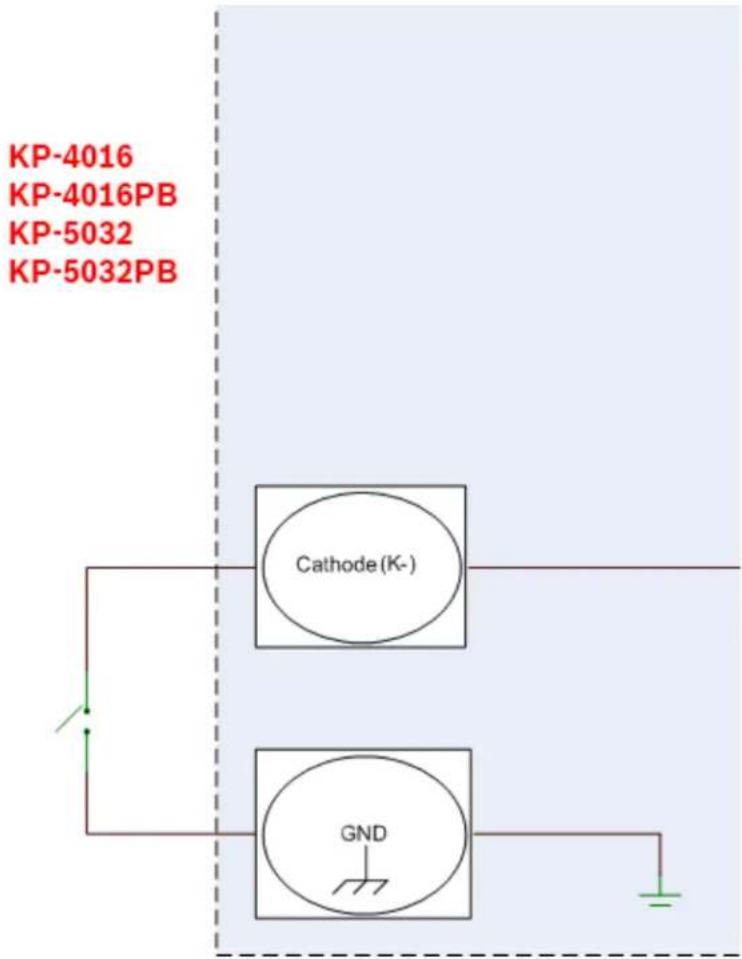
FIGURE 8. Footswitch Cable Drawing
Intercom Keys and Displays
Color Display Descriptions for Intercom Keys
The KP-Series display uses colors to distinguish the type of key assignment assigned to the key. Use Table 2 to help determine the default key assignment colors.
TABLE 2. Default Key Colors
| Default Color Description | ||
| Amber Waiting for Footswitch | ||
| Bright Green Listen Indicator, Local Matrix | ||
| Brown IFB Special List | ||
| Teal Point-to-Point | ||
| Dark Yellow ISO | ||
| Light Blue Unassigned, Test Mode (with Talk and Listen Indicators) | ||
| Pale Yellow Special Functions | ||
| Magenta Relay | ||
| Pink Party Line | ||
| Red Remote Matrix | ||
| Salmon IFB, Talk Indicator | ||
| Pale Green | Special List | |
| Periwinkle | UPL Resource | |
Display Icons
Display Icons are used to indicate the accessories and features enabled, disabled, active, or inactive. Use Table 3 for a complete description of each icon seen on the KP-Series.
TABLE 3. Display Icon Descriptions
| Icon Icon | Name Description | |
 | Matrix Connected The keypanel is connected to the Matrix. This icon briefly displays at connection. | |
 | Disconnected From Matrix | There is no connection between the Matrix and the keypanel. This icon is displayed as long as there is no Matrix data connection.NOTE:When the keypanel is disconnected, it displays its Device Name (for OMNEO) or IP Address (for RVON) device connections. |
 | Firmware Download | Firmware is being downloaded to the keypanel. A progress bar displays: chunk progress overall progress chunk/overall progressNOTE:For more information, see “Download Firmware to the Keypanel From AZedit” on page 161. |
 | Footswitch Active The footswitch is active. | |
 | Footswitch Enabled The footswitch is enabled, but not active.NOTE:When a keypanel key is latched while the Footswitch is enabled, the key display turns amber to signify it is waiting for the footswitch. | |
 | Front Headphones The front headphones are enabled. This indicates the front headset microphone is not enabled. | |
 | Front Headset The front headset is enabled. | |
 | Front Headset Mic Muted | The front headset mic is muted. |
 | Front Microphone The front microphone is enabled. | |
 | Front Microphone Muted | The front microphone is muted.To mute the front microphone, see “Mute the Microphone” on page 64. |
 | Front Speaker The front speaker is enabled.To enable the front speaker, see “Audio Options Menu, Speaker” on page 210. | |
 | Front Speaker Muted | The front speaker is muted. |
| [IH626] | Rear Headphones The rear headphones are enabled. This indicates the rear headset mic is not enabled.To enable the rear headphones, see “Audio Options Menu, Headset Speaker” on page 203. | |
TABLE 3. Display Icon Descriptions
| Icon Icon | Name Description | |
 | Rear Headset The rear headset is enabled. | |
| HDSTMUTE | Rear Headset Muted | The rear headset mic is muted. |
 | Rear Microphone The rear microphone is active.To activate the rear microphone, see “Audio Options Menu, Panel Mic” on page 209. | |
 | Rear Microphone Muted | The rear microphone is muted.To mute the rear microphone, see “Mute the Microphone” on page 64. |
 | Rear Speaker The rear speaker is active.To activate the rear speaker, see “Audio Options Menu, Speaker” on page 210. | |
 | Rear Speaker Muted | The rear speaker is muted. |
 | Both Headphones Both front and rear headphones are enabled. This indicates both the front and rear headset mics are disabled.To enable the front headphones, see “Audio Options Menu, Headset Speaker” on page 203. | |
 | Both Headsets Both front and rear headsets are active. | |
 | Both Headsets Muted | Both front and rear headset mics are muted. |
 | Both Microphones Both front and rear microphones are enabled. | |
 | Both Microphones Muted | Both front and rear microphones are muted.To mute the front microphone, see “Mute the Microphone” on page 64. |
 | Both Speakers Both front and rear speakers are enabled.To enable the front speaker, see “Audio Options Menu, Speaker” on page 210. | |
 | Both Speakers Muted | Both front and rear speakers are muted. |
 | Snoop Tally Active Snoop Tally is Active on the keypanel.You must have the Hot Mic enabled to use snoop tallies.To enable snoop tallies, see “Service Menu, Snoop Tally” on page 256. | |
 | Hot Mic The hot mic is active.To activate Hot Mic, see “Audio Options Menu, Matrix Out” on page 206. | |
 | Tone 1kHz Enabled | Tone 1kHz is enabled on the keypanel.To enable tone 1kHz, see “Audio Options Menu, Tone Gen” on page 211. |
 | Tone 500Hz Enabled | Tone 500Hz is enabled on the keypanel.To enable tone 500Hz, see “Audio Options Menu, Tone Gen” on page 211. |
TABLE 3. Display Icon Descriptions
| Icon Icon | Name Description | |
 | OMNEO Enabled The | The OMNEO matrix interface is enabled on the panel. For more information on OMNEO Offers, see“Menu System, OMNEO Offers” on page 235. |
 | RVON Enabled The | RVON matrix interface is enabled on the panel. |
 | Analog The Analog matrix interface is enabled on the panel. | |
 | Virtual Key Assignment | Keys are active on a virtual EKP that are not being displayed. For more information, see “Key Options Menu, Panel Swap” on page 230.NOTE: A talk or listen bar (or both) displays to indicate which type of virtual keys are active. |
 | AFK The AFK (Away From Keypanel) icon displays when a user activates AFK mode and steps away from the keypanel. Callers are notified the user is AFK and can then leave a message. | |
 | VM The Voice Message icon displays when voice messages are present on the keypanel.The badge in the lower left hand corner displays the number of stored messages. | |
 | Recording The Recording icon is shown if an AFK panel is actively recording a message or if the 30-second rolling buffer is enabled. | |
 | Supervisor Mirroring | The Supervisor icon signifies the keypanel is mirroring another keypanel and can make changes to the other keypanel, known as a Target. For more information, see “Service Menu, Mirror (Control Package Only)” on page 248. |
 | Target Mirrored The | Target icon signifies the keypanel is being mirrored by another keypanel, known as a Supervisor. This keypanel can be taken control of by the Supervisor. For more information, see “Service Menu, Mirror (Control Package Only)” on page 248. |
 | Matrix In Mute The Matrix Input volume is muted. When the Matrix Input volume is adjusted down to mute, the panel displays this flashing icon as a warning there is no audio from the Matrix. | |
 | Audio Package Installed | The optional audio package is installed. When the audio package is installed, this icon appears at power-up and continues to display until the keypanel connects to the intercom. For more information, see “Audio and Control Packages” on page 303. |
 | Control Package Installed | The optional control package is installed. When the control package is installed, this icon appears at power-up and continues to display until the keypanel connects to the intercom. For more information see, “Audio and Control Packages” on page 303. |
Keypad Reference View
With both the KP-4016/4016PB and KP-5032/5032PB, there are three tiers of operation for a keypanel's keypad: Primary Mode, SHIFT Mode, and Dial Mode.
Primary Mode
Primary Mode is used for the most common keypanel functions, such as CLR, SEL, and accessing the Main menu. There are no special keypad sequences to use these functions.
Dial Mode
DIAL Mode is used to complete telephone operations. For more information, see "Telephone Interface (TIF) Operation" on page 259. When the keypanel is in DIAL mode, the keypad keys support the standard telephone DTMF keypad configuration as a third tier function. The DTMF keypad is seen in the upper-left corner of the keypad keys.
SHIFT Mode
SHIFT Mode contains secondary functions used to access more utilities on the keypanel. The SHIFT mode functions are located on the primary keypad keys. The shift functions available are COPY, DIAL, DROP, LEFT, RIGHT, LSTN, VM, INFO, UPG2 AFK, and TYPE.
NOTE: By default, the keypad backlight changes to white when the keypad is in SHIFT mode. For more information, see "Service Menu, Keypad" on page 243.
To access SHIFT Mode, do the following:
-
On the keypad, press the SHIFT button.
-
On the keypad, press the SHIFT mode button desired.
NOTE: Once SHIFT mode is entered, exit the mode by pressing the SHIFT key again, without pressing any other keys.
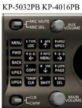

FIGURE 9. KP-5032, KP-5032PB, KP-4016, and KP-4016PB Keypad
| IMPORTANT: | When SHIFT +appears in this manual, the user is instructed to press the SHIFT key followed by the next keypad key. The SHIFT key and the keypad key should not be pressed simultaneously.If the user is instructed to press two keys simultaneously, this manual uses the phrasepress and hold. |
| Keypad Button | Shift Function | Dial Function | Description | |
| LOC button | TYPE 1 | The LOC (1) button displays the list of available intercoms (LOCations) available to scroll from. Select an intercom name to access the scroll lists for that intercom.The TYPE button displays the keypanel assignment types available for use. | ||
| ↑button AFK 2 | The ↑(2) button moves you upward through the scroll list or available key assignments one at a time.The AFK (Away From Keypanel) button is used to notify the caller the keypanel user is away from the keypanel. The caller is then able to leave a voice message for the user. For more information, see “Voice Messaging (Audio Package Only)” on page 68.To enable AFK on the keypanel, do the following:> Press the SHIFT+AFK (2) buttons.A yellow AFK icon appears on the left of the left panel display.NOTE: For more information, see “Voice Messaging (Audio Package Only)” on page 68. | |||
| UPG1 button | UPG2 3 | The UPG 1 and UPG 2 buttons are used to assign frequently used menu items. These button allow users to access the menu items quickly. UPG buttons can also bcLOCprogrammed to trigger GPI outputs or panel swap events. | ||
| ← button ← 4 | The ←/←← (4) button moves you backwards through the menu options or available key assignments one at a time or by the page. | |||
| MENU button | INFO 5 | The MENU/INFO (5) button is used to access the top level menu structure or access a secondary menu of commonly used features (see, “INFO button” on page 46).The MENU button is used to access the top-level menu structure.> Press the MENU button once.The top-level menu appears in the panel display.To access the INFO menu, do the following1. Press the SHIFT button.2. Press the MENU/INFO (5) button.The INFO menu appears in the panel display.For more details about the INFO button, see “INFO button” on page 46. | ||
| → button → 6 | The →/→→ (6) button moves you backwards through the menu options or available key assignments one at a time or by the page. | |||
| COPY button | COPY key-to-key | 7 | The COPY (7) button is used to copy an incoming call key assignment from the CWW to a specific keypanel key. | |
| Lever Key Pushbutton | ||||
| To copy a CWW to a talk key using a lever key keypanel, do the following:>Press COPY + the target talk key.To copy a CWW to a listen key using a lever key keypanel, do the following:>Press COPY + the target listen key.To copy a talk key to a talk key, do the following:1. Press SHIFT + COPY.2. Press the source key.3. Press the target key.NOTE:You can also copy from key to key by pressing the COPY+SEL buttons, and then tapping the source key and then the target key.To copy a talk key to a listen key, do the following:1. Press COPY + SEL.2. Press the source talk key.3. Press the target listen key.To copy a listen key to a listen key, do the following:1. Press COPY + SEL.2. Press the source listen key.3. Press the target listen key.To copy a listen key to a talk key, do the following:1. Press COPY + SEL.2. Press the source listen key.3. Press the target talk key. | To copy a CWW to a talk key using a pushbutton keypanel, do the following:>Press COPY + the target key.To copy a CWW to a listen key using a pushbutton keypanel, do the following:>Press COPY + SHIFT + the target key.To copy a talk key to a talk key, do the following:1. Press SHIFT + COPY.2. Press the source key.3. Press the target key.NOTE:You can also copy from key to key by pressing the COPY+SEL buttons, and then tapping the source key and then the target key.To copy a talk key to a listen key, do the following:1. Press COPY + SEL.2. Press the source key.3. Press SHIFT.4. Press the target key.To copy a listen key to a listen key, do the following:1. Press COPY + SEL + SHIFT.2. Press the source key.3. Press SHIFT.4. Press the target key.To copy a listen key to a talk key, do the following:1. Press COPY + SEL + SHIFT.2. Press the source key.3. Press the target key. | |||
44 Basic Operation KP Series
| Keypad Button | Shift Function | Dial Function | Description |
| ↓button VM 8 | The ↓ (8) button moves you downward through the scroll list or available key assignments onc at a time.The VM button is used to retrieve voice messages left on the keypanel.To retrieve voice messages, do the following:1. Press the SHIFT+VM (8) buttons.A scroll list of messages appear in the display panel.2. Using the UP and DOWN arrows, scroll to thevoice messageyou want to listen to.For more information, see “Voice Messaging (Audio Package Only)” on page 68. | ||
| PAGE button | Enters graphical page mode | 9 | The PAGE button is used to access a different setup page. You can configure up to 15 pages in the intercom system. The default number of pages is four. To configure the number of pages available use the Intercom Configuration window, on the Options Page in AZedit.To program a new page directly, do the following:>Press the PAGE button, <#>, then tap a key.To enter the graphical page change mode, do the following:>Press the PAGE+ SEL buttons.ORPress the SHIFT+PAGE buttons. |
| (For Pushbutton Models Only) | LSTN | The LSTN mode button is used to toggle pushbutton presses from talk to listen key presses.NOTE: For more information on the pushbutton listen mode, see “Pushbutton” on page 49.To enter the listen menu mode, do the following:1. Press the SHIFT-LSTN button.The pushbuttons switch to listen mode and a Toggle Key Listen States message appears on keypanel display2. Press thekeypanel buttonfor which to listen.The keypanel buttons now operate on listen key states rather than talk key states.NOTE: When not in listen menu mode (SHIFT+LSTN), holding the SHIFT button and pushing a keypanel button also toggles the listen state of the keypanel button pushed.To leave listen mode, do the following>Press the CLR button.The keypanel leaves listen mode. | |
| CLR button | DROP * | The CLR/DROP (*) button is used to hide the CWW window or the CLR button functions as a back button when a menu is displayed.To clear a menu, do the following:> Press and hold the CLR button for half a second.If the CLR/DROP button is pressed when in TIF DIAL mode, it hangs up the TIF connection.To access the DROP function, do the following:1. Press the SHIFT button (0), and then the DROP button.Tap Key appears in the panel display.2. Tap the key you want to drop the call from. | |
| SHIFT button | 0 | The SHIFT (0) button accesses the secondary keypad actions such as INFO, DROP, etc. on both the KP5032/4016 and the KP5032/4016PB keypanels.NOTE: On the Pushbutton keypanels, the SHIFT button, when held down while pushing a keypanel key, toggles the listen state of the button. | |
| SEL button | DIAL # | The SEL/DIAL (#) button is used to select options highlighted in the menu structure.> Press SHIFT+DIAL and then press the TIF key to enter TIF Dial mode. |
KP-5032/5032PB Only Keypad Keys
| Keypad Button | Shift Function | Description |
| MENU button | UPG 5 | The MENU button is used to access the top-level menu structure.>Press the MENU button once.The top-level menu appears in the panel display.NOTE:If the keypad backlight mode is set to Activate (Service|Keypad|Backlight), you must press the MENU button twice to access the top-level menu. |
| FWD button | UPG 6 | The FWD button moves you forward through the menu option highlighted. For example, if Display is highlighted in the panel display and FWD is pressed, the second level of the display menu appears. |
| BACK button | UPG 7 | The BACK button moves you backward, one level, through the menu structure.NOTE:If you are at the top-level of the menu structure and press BACK, you cannot move backward any further. |
| UPG 3 button | UPG 8 | The UPG 3 button is used to assign a frequently used menu item. This allows users to access the menu item quickly. UPG buttons can also be programmed to trigger GPI outputs or panel swap events. |
| UPG 4 button | UPG 9 | The UPG 4 button is used to assign a frequently used menu item. This allows users to access the menu item quickly. UPG buttons can also be programmed to trigger GPI outputs or panel swap events. |
INFO button
The INFO button is used to access commonly used features and configuration options for the keypanels. These include the following:

| Feature Description | |
| Panel ID Displays the port number and alpha of the keypanel. | |
| Level 2 Displays the Level 2 key assignments on the keypanel. | |
| Listen Displays the listen key assignments on the keypanel. | |
| Callers Displays a list of current callers to the keypanel. | |
| Assign Types Displays the assignment types of all the configured keypanel keys. | |
| Matrices Displays the Matrix for each key assignment. | |
| Tone Opens the Tone Generator menu. For more information, see “Audio Options Menu, Tone Gen” on page 211. | |
| Setup Pages | Displays the setup pages assigned to each row of keys. You cannot change setup pages from this menu. |
| Reset Vols | Opens the Key Volumes Reset menu. For more information, see “Audio Options Menu, Key Volumes” on page 205. |
| Hidden Asgns | Displays key assignments assigned to virtual keys (ie, assignments not currently visible). |
| MAC Address | Displays the MAC Address of the keypanel. |
| Test Panel | Enables the Test Panel feature. For more information, see “Service Menu, Test Panel” on page 257. |
| Version | Displays the firmware version of the KP-5032/4016. For more information, see “Display Menu, Version” on page 217. |
To access the Info Menu, do the following:
- On the keypad, press the SHIFT button.
- On the keypad, press the INFO MENU (5) button.
The INFO menu appears in the panel display.
NOTE: To exit the INFO menu mode, press the CLR button.
Breadcrumb Menu Navigation
Breadcrumb Navigation is a graphical aid to help users know where they are in the menu structure. The breadcrumb menu visually lays out a path of options selected up to the current menu position. It appears as a horizontal line above the menu options (shown in Figure 10). For more information, see “Service Menu, Display” on page 239.
NOTE: Breadcrumbs navigation is only available on 2RU models (KP-5032/5032PB and DKP models).
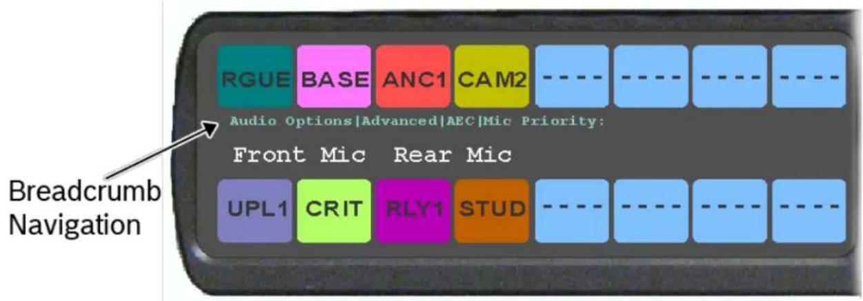
FIGURE 10. Breadcrumbs Navigation
Menu Navigation and Shaft Encoder Knobs
While the keypanel is in menu mode, the AUX Volume shaft encoder is used to move the selection left and right. In the case of a single menu item with up and down control, the shaft encoder is rotated to scroll through the available selections. This is particularly convenient when setting the keypanel brightness or gain. Also, pressing the Aux Volume shaft encoder while in menu mode is the equivalent to SEL key operation. Conversely, pressing the MAIN Volume shaft encoder in menu mode is the equivalent to the CLR key operation. Double-tapping the AUX Volume shaft encoder, can also be used for the CLR operation.
Other navigation options:
- Press and hold the AUX/MENU shaft encoder to exit the menu.
CLR Button
The CLR button is used either as the BACK function while in MENU mode or to exit MENU mode completely.
To go back one menu level, do the following:
Press the CLR button once.
To exit the menu, do the following:
Press and hold the CLR button for half a second. OR Press the CWW key up.
Basic Key Operation
Coupled with the traditional operation of lever keys, the KP-5032/4016 keypanels also have an integrated LCP (Level Control Panel). This feature allows the user to adjust the volume for individual keys on the keypanel. Figure 11 displays the different key positions and their meanings.
Lever Key
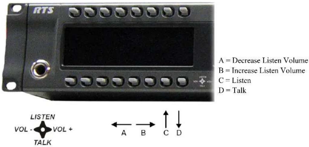
FIGURE 11. Key Function Position Explanation
To talk on the lever key keypanel, do the following:
Press down on the keypanel key you want to use.
To listen on the lever key keypanel, do the following:
Press up on the keypanel key you want to use.
To adjust the listen volume, do the following:
Press the lever key forward (increase) or backward (decrease) to adjust the listen volume.
Pushbutton
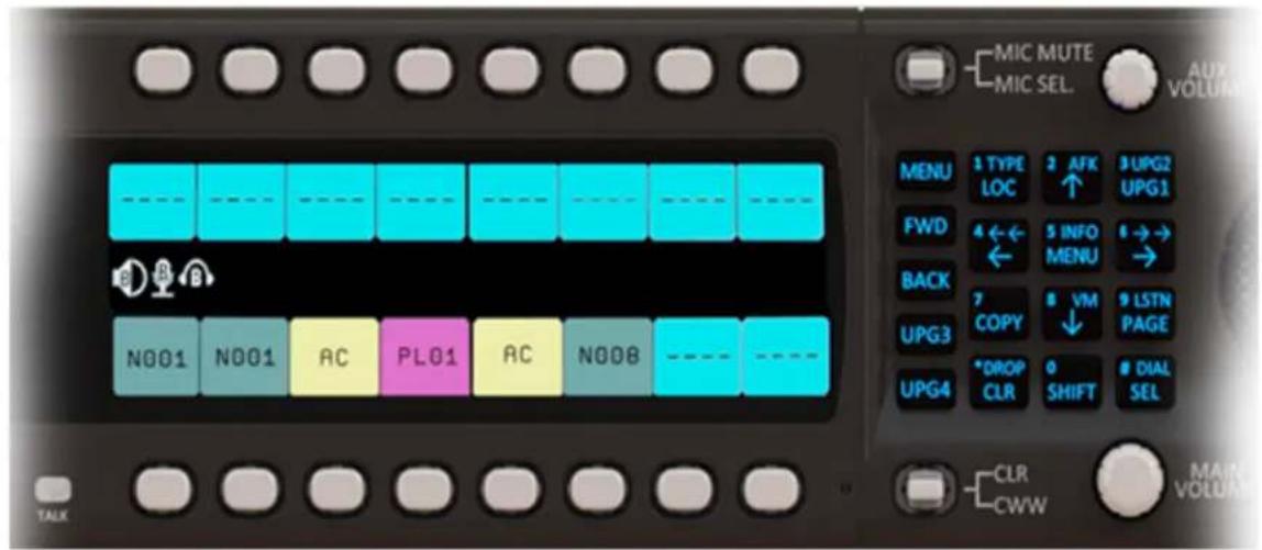
FIGURE 12. Pushbutton Key Function Explanation
To talk on the pushbutton keypanel, do the following:
Press the keypanel key you want to use.
To listen on the pushbutton keypanel, do the following:
- Press SHIFT+PAGE (LSTN).
The keypanel switches to listen mode and Toggle Listen Key Status appears in the display panel.
- Press the keypanel key to which you want to listen.
OR
While pressing the SHIFT button, press the key to which you want to listen.
Once you have pressed the keypanel key, you can release the SHIFT button. The listen action stays active until the last listen key you press is released.
NOTE: Multiple listen keys can be pressed once the initial listen key has been activated.
To adjust the listen volume, do the following:
- While holding the SHIFT button, press and hold the key to which you want to listen.
Once you have pressed the keypanel key, you can release the SHIFT button.
- While holding the keypanel key, turn the AUX shaft encoder to the right to increase or to the left to decrease the volume.
IMPORTANT: When the last listen button is released and if the SHIFT button is no longer held, the next button push is treated as a talk key.
Talk/Listen Indicator
The Talk/Listen Indicator, shown in Figure 13, displays a visual indicator when the talk and/or listen key is active. The talk and listen states of each key are represented by an LED-like horizontal bar at the bottom (talk) and top (listen) of each key.
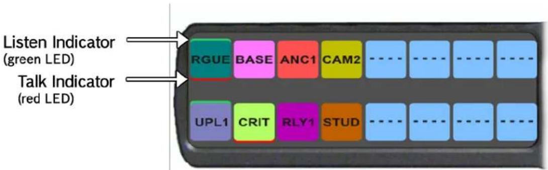
FIGURE 13. Talk/Listen Indicators
By default, the listen indicator is green and the talk indicator is red. You can change the colors of the indicator by using the Key Color Window in AZedit. For more information, see "Keypanel Color Window" on page 75.
Key Gain Adjustment
The Key Gain Adjustment is used to change the crosspoint listen gain on a specific key from the Matrix. This adjustment is automatically reflected in AZedit on the Crosspoint Gains window. (System|Gains|Crosspoint).
The range for this feature is +6 dB to -80 dB and Mute.
NOTE: Key gain can only be adjusted when the listen function listens to a PP, PL, or, an IFB with an Auto-Talk function on the listen key and a Listen Source programmed for the IFB.
To adjust the crosspoint gain using the keypanel key, do the following:
On the KP-5032/4016 front panel:
- Press the keypanel key to the right to increase the listen gain for the selected key assignment.
- Press the keypanel key to the left to decrease the listen gain for the selected key assignment. A volume status bar ( ) and the volume level, in dB, appear on the specified key in the panel display.
To adjust the crosspoint gain using the AUX Volume encoder shaft, do the following:
- Lift and hold the keypanel key for which you want to adjust the crosspoint gain.
- Turn the AUX Volume encoder shaft to the right to increase the gain. OR
Turn the AUX Volume encoder shaft to the left to decrease the gain.
To adjust the crosspoint gain on a pushbutton keypanel, do the following:
- Press SHIFT + PAGE (LSTN).
The keypanel switches to listen mode and Toggle Listen Key Status appears in the display panel.
- Press the keypanel key to which you want to adjust the gain.
NOTE: Also, press and hold the SHIFT button and then press and hold the keypanel key for which you want to adjust the crosspoint gain. Once you have pressed the keypanel key, you can release the SHIFT button.
- Turn the AUX Volume shaft encoder to the right to increase the gain.
OR
Turn the AUX Volume shaft encoder to the left to decrease the gain.
NOTE: The volume bar shows a full width icon, but only colors the portion that represents volume. The remainder of the bar is shown in black. This is so when the key gains are always displayed, the user knows when a key is muted, as opposed to a key that cannot have gain adjusted.
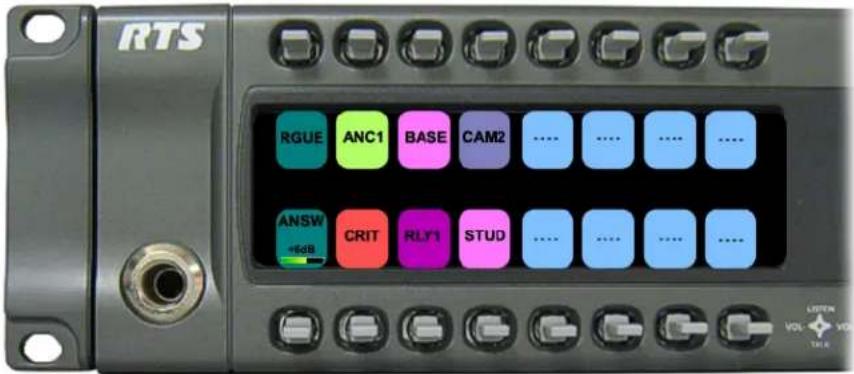
Keypanel Volume Adjustments
By default, the main volume control adjusts the output volume for the speaker (front/rear) or headset (front/rear), whichever is currently active.
IMPORTANT:
If the speaker output volume is adjusted to Mute, then the panel displays a flashing SPKR MUTE icon as a warning there is no audio to the front, rear, or both speakers.

If the headset output volume is adjusted down to Mute, then the panel displays a flashing HDST MUTE icon as a warning there is no audio to either the front, rear, or both headsets.

Output volume ranges from +10 dB to -48 dB and Mute.
NOTE: When speakers and/or headset volumes are ganged together a split volume bar displays in the keypanel display. The front speaker or headset is the top portion of the bar, while the bottom portion of the bar is the rear speaker or headset volume.
For more information on Gang Volumes, see "Audio Options Menu, Ganged Vols" on page 201.

To adjust output volume level, do the following:
On the keypanel, turn the MAIN VOLUME encoder to the right to increase the volume for the selected output. OR
Turn the MAIN VOLUME encoder to the left to decrease the volume for the selected output.
NOTE: When the MAIN VOLUME encoder is turned, the volume level bar appears in the panel display.

NOTE: Volume adjustments can be saved as power-up defaults using "Menu System, Save Config" on page 236.
To select a different output volume control, do the following:
On the keypanel, push the MAIN VOLUME encoder once.
The main volume focus switches to the next available output and displays above the volume level bar.

Aux Volume Adjustments
By default, the Aux Volume shaft encoder knob adjusts the selected input volume, which can include Aux 1-2, Matrix Input, or OMNEO 1-8, depending on licensing and whether the connection is via OMNEO or AIO.
Input volume ranges from +10 dB to -48 dB and Mute.
NOTE: When the Matrix Input volume is adjusted down to Mute, then the panel displays a flashing MTX MUTE icon as a warning there is no audio from the Matrix.

To adjust listen volume level, do the following:
On the keypanel, turn the AUX VOLUME encoder to the right to increase the volume for the selected input. OR
Turn the AUX VOLUME encoder to the left to decrease the volume for the selected input.
NOTE: When the AUX VOLUME encoder is turned, the volume level bar appears in the panel display.

NOTE:
- Volume adjustments can be saved as power-up defaults using "Menu System, Save Config" on page 236.
- The inputs are available if they are enabled and mixed to an output.
To change the focus of the volume control, do the following:
On the keypanel, push the AUX VOLUME shaft encoder once.
The aux volume focus switches to the next available input.

Priority Call Volume Control
Priority Call Volume Control is used to mark a keypanel as a priority caller. When a priority caller talks to another keypanel, a minimum crosspoint volume (configurable in AZedit) is enforced for the duration of the call to ensure the caller is heard, even if the target panel has set the listen volume to a lower volume.
In addition, a minimum volume of -6 dB on the speaker and headset of the target panel is also enforced when receiving a call from a priority caller (also ensuring the caller is heard, even when the target panel's headset and speaker volume is turned down. Once the call is completed, the previous speaker, headset, and crosspoint volumes are restored when the priority caller stops calling.
When a panel is the target of a priority call, the speaker, headset, and volume display are shown with an orange background indicating a priority call is in progress.
NOTE: The volumes are never lowered by the priority call, but are raised to the minimum values for the duration of the call if they had lower values to begin with.

FIGURE 14. Incoming Priority Call Volume Control Keypanel
Available crosspoint values range from: +6 dB to -80 dB and Mute.
By default, the priority call volume is set to +0.0 dB.
To configure priority call volume control, do the following:
-
On the Keypanels/Ports screen in AZedit, select the port to set with priority call volume control.
-
Click the Edit button.
The Keypanel/Port Configuration screen appears.

- Click the Advanced tab.
The Advanced Page appears. - Select the Priority Call Volume check box.
- From the Priority Call Volume drop down box, select the crosspoint volume level for the priority caller.
- Click the Apply button.
- Send the change to the intercom.
Operation of Intercom Keys with Auto Functions
NOTE: Assignment of keys with auto functions is described in the programming section that follows.
Operation of keys with auto functions, is as follows:
Talk+auto follow Talk and listen can be activated separately. The listen assignment listens to whatever is assigned to the talk key.
Talk+auto listen Both talk and listen activate when talk is activated.
Talk+auto mute Listen turns off when talk is activated.
Talk+auto reciprocal Listen is always on and talk may be turned on or off.
Talk+auto table If an IFB talk key has an auto table listen assignment, talk and listen are independently activated. The listen key listens to whatever is defined as the IFB Listen Source for the IFB assigned to the talk key.
All Call Activating this key activates all keys to the left of it, up to, but not including another All Call key.
Talk+DIM If a point-to-point key has the DIM function as a level 2 talk assignment, activating the key causes the crosspoint levels to diminish for any other intercom ports currently listening to the same destination and are in the same DIM tables.
Operation of Intercom Keys with Options
Group Option Keys
Activating the master key in a key group activates all keys in the group according to each key's individual key assignment. Activating a slave key does not affect any other keys in the group. For more information, see "Key Options Menu, Key Groups" on page 227.
Solo Key
Activating a key with the solo option causes all other keys to turn off until the solo key is turned off. For more information, see "Key Options Menu, Solo" on page 233.
Exclusive Key
Activating a key with the exclusive option causes all other Exclusive keys to turn off when activated. Unlike the solo option, when exclusive is deactivated, the keys turn off and stay off. For more information, see "Key Options Menu, Exclusive" on page 225.
Lock Key
A key with the lock option on it is locked in the on or off position and cannot be changed until the lock is removed. For more information, see "Key Options Menu, Lock (Button Lock)" on page 229.
Chime Key
When a chime is configured on a key and a call is received, the chime is activated. You can configure length and type of chime for the key, as well. For more information, see "Key Options Menu, Chime" on page 224.
Clear Keys
Clearing keys is used to remove any key options assigned to a specific key or UPG button assignment. For more information, see "Key Options Menu, Clear" on page 225.
Latching Keys
Latching keys on a keypanel gives the user hands-free operation where keys stay active after quickly tapping the key. For more information, see "Key Options Menu, Latching" on page 228.
Operation of Intercom Talk Keys with the Speaker DIM Setting
Activating any talk key causes the speaker or headphone volume at the keypanel to diminish by the amount specified in the DIM menu item on the Service menu. For more information, see "Audio Options Menu, Dim" on page 200.
NOTE: Do not confuse this with the Talk+DIM auto function previously described. Talk+DIM affects the speaker or headphones on other keypanels when a particular talk key is activated on the keypanel. Speaker DIM affects the speaker or headphone level on the keypanel when any talk key on the keypanel is activated.
Operation of Intercom Keys assigned to TIF Ports
If a keypanel key is assigned to talk to an intercom port designated as a TIF port in AZedit, placing the key in the talk position activates the keypanel dialing menu. For more information, see “Telephone Interface (TIF) Operation” on page 259.
To designate an intercom port as a TIF port, do the following:
- In AZedit, select the port to designate as a TIF port on the Keypanel/Port window.
- Click the Edit button.
- On the Advanced tab, select the Port is TIF check box.
- Send the change to the intercom system.
User Quick Select Scrolling
User Quick Select Scrolling is a fast and easy way to call or assign a point-to-point key on the keypanel.
To use the User Quick Select Scroll feature to call a user, do the following:
- On the keypad, press the left and right arrow buttons to scroll through the list of point-to-point connections available.
The selected port is highlighted in white.
NOTE:
- You can also use the left and right arrow buttons to page scroll through the list of ports available. Page scroll is useful when you have a large intercom system and you want to find a port quickly.
- You can also use the AUX Shaft encoder to quickly scroll through the list once you are in the scroll list menu.
To page scroll, do the following:
- Press the SHIFT button before pressing the left or right arrow buttons.
OR
Press the SHIFT button and then press and hold the arrow button to repeat scrolling a page at a time.
Remember, when the key is released, SHIFT Mode is exited.
- When the port is selected, press down on the CWW key to talk to the selected port.
Graphical Call Waiting Window
The KP-Series keypanel can keep a history of the last nine callers and display them in a scrollable, graphical window above keys 15 and 16. The CWW displays three calls at a time (only two in Unicode mode) with a scroll arrow appearing if there are more than three calls in the list.
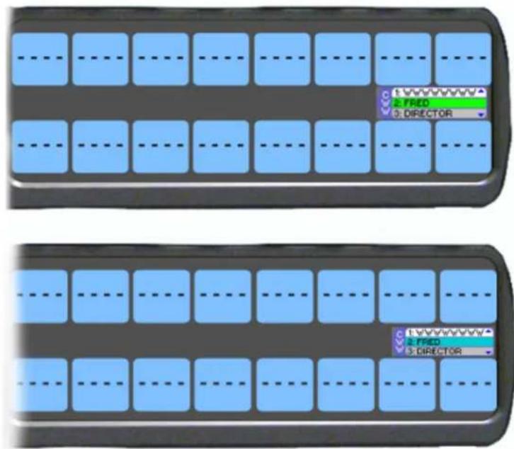
FIGURE 15. Graphical Call Waiting Window/ KP-5032

FIGURE 16. Graphical Call Waiting Window/ KP-4016
TABLE 4. Graphical CWW Call Description
| Item Description | |
| New Call White background | |
| Selected Call / Not Talking Cyan background | |
| Selected Call / Talking Green background | |
| Old Call Gray background |
Graphical Call Waiting Window Operation
Use Table 4 on page 62 and Figure 15 on page 61 to understand the different states of the CWW.
Display or Hide the CWW
To display the CWW, do the following:
On the keypanel, lift up on the CWW key. The graphical call waiting window appears.
To hide the CWW, do the following:
Press the CLR button. The CWW closes.
NOTE: If the CWW list is visible and not empty, it remains visible until hidden. If the CWW list is visible, but empty, it auto-hides after a five-second timeout.
Incoming Calls
When a call is received at the keypanel, the graphical CWW list appears on the keypanel display. The CWW can be configured to retain call history for three, up to nine calls. The most recent call is inserted at the top of the graphical CWW list (position 1) with a white background (See Figure 15 on page 61). Other items in the CWW list are shifted down, as necessary. When a new call is received, the last call in the list is dropped, unless it is highlighted in the graphical CWW. In this case, it cannot be shifted off the CWW list.
For more information on how to configure the CWW, see "Service Menu, CWW" on page 238.

KP-5032

KP-4016
FIGURE 17. Graphical Call Waiting Window Highlighted Call
To scroll the CWW list, do the following:
When the CWW list is visible, press the arrow up button or the arrow down button. The highlight moves through the scroll list.
To answer a call on the graphical CWW, do the following:
- Scroll the CWW to highlight the call you want to answer.
The highlighted call is shown with a cyan background.
- Press and hold the CWW key to talk to the caller.
The highlight in the CWW list turns green and moves to the top of the list when talking with the caller.
- Release the CWW key to stop talking.
The call is ended. The background of the caller in the CWW list turns a light gray (if not highlighted).
Clearing the CWW List
To clear the CWW list, do the following:
- If the CWW is not visible, press the CWW key up to make it visible and the call selected.
- Use the up and down arrows to navigate to the call to remove.
- Press the CWW key up, to clear the selected entry.
- Repeat steps 2 & 3, as necessary.
Mute the Microphone
When the Mic Mute key is lifted up, the corresponding microphones are muted. The Mic Mute key can be disabled or configured to operate in either Toggle or Momentary mode.
For more on Mic Mute Modes, see "Audio Options Menu, Mic Mute" on page 208.
On the KP-4016/4016PB, the Mic Mute and Mic SEL keys are incorporated into key 15, see Figure 18.

FIGURE 18. KP-4016 Mic MUTE and Mic SEL
NOTE: See "Mic Mute" on page 105, for information on Mic Mute Options.
Mic Select
Every mic (input) or speaker/headset (output) can be configured as Always On or Enabled, Disabled, or Switched. Only mics, speakers, or headsets set to switched are controlled by the MIC SEL key.
For more information, see:
• “Audio Options Menu, Headset Speaker” on page 203.
• "Audio Options Menu, Panel Mic" on page 209.
• "Audio Options Menu, Headset Mic" on page 201.
TABLE 5. Source Configuration Matrix and Display icons
| ALWAYS ON/ENABLED SWITCHED DISABLED ICON DISPLAYED | |||
| Panel Mic | |||
| Front and Rear | |||
| Front Rear | |||
| Rear Front | |||
| Front Rear | |||
| Rear Front | |||
| Front and Rear No icons display on the keypanel | |||
| Headset Mic | |||
| Front and Rear | |||
| Front Rear | |||
| Rear Front | |||
| Front Rear | |||
| Rear Front | |||
| Front and Rear No icons display on the keypanel | |||
TABLE 5. Source Configuration Matrix and Display icons
| ALWAYS ON/ENABLED SWITCHED DISABLED ICON DISPLAYED | ||||
| Speaker | ||||
| Front and Rear |  | |||
| Front Rear |  OR OR  | |||
| Rear Front |  OR OR  | |||
| Front Rear |  | |||
| Rear Front |  | |||
| Front and Rear No icons display on the keypanel | ||||
| Headset | ||||
| Front and Rear |  | |||
| Front Rear |  OR OR  | |||
| Rear Front |  OR OR  | |||
| Front Rear |  | |||
| Rear Front |  | |||
| Front and Rear No icons display on the keypanel | ||||
Setup Pages
Setup Pages are used to allow access to more key assignments than physical keys on the keypanel. This is useful for sharing a keypanel because setup pages can be used to swap between the key assignments used for each person. An alternative to Setup Pages is Panel Swap (see "Key Options Menu, Panel Swap" on page 230). Note, with Panel Swap, your system must be configured for more keys per panel, whereas with Setup Pages, you do not need to increase the number of keys per panel, but can simply assign different setup pages to each row of keys.
Up to 15 setup pages per keypanel port can be configured.
By default, eight pages are available.
IMPORTANT: To change the Setup Pages available for ports, in AZedit go to Options | Intercom Configuration | Options tab. Change the Setup Pages per port field to the number of pages needed. Changing the number of setup pages will cause the intercom to reboot and restart.
NOTE: To add key assignments to the setup pages, see "Menu System, Key Assign Menu" on page 218.
To open and assign setup pages, do the following:
-
Press the PAGE key. The Page menu appears in the display screen.
-
Enter a digit (page number). OR Press SEL to enter graphical mode.
NOTE: By pressing SEL, you no longer have to complete Step 3.
- Tap a key to assign that page to the key row.
To toggle between setup pages, do the following:
IMPORTANT: You must be in graphical page mode to be able to toggle between pages.
- Using the left and right arrows, change the page on the current key row.
- Press the SEL key (or wait 2 seconds for auto-select to engage).
To change the highlighted key row in the graphical mode, do the following:
Using the FWD/BACK or UP/DOWN keys, change the highlighted key row. OR Press the SHIFT + LEFT buttons or the SHIFT + RIGHT buttons to change the highlighted key row.
Menu Passwords
The keypanel is capable of locking the entire menu structure or only the service menu. This is implemented through AZedit (System | Miscellaneous | Keypanel Menu Password). For more information, see the AZedit user manual (p/n F01U239453).
NOTE: Only numerical passwords are permitted.
To enter a menu password at the password prompt, do the following:
- Press the MENU button.
PASSWORD: appears in the keypanel display screen.
-
Using the keypad, enter the password for the menu.
-
Press the SEL key.
When the password is entered correctly, the menu appears.
NOTE:
- Use the CLR button, double-tap the AUX shaft encoder, or single-tap the MAIN shaft encoder to erase the last digit.
- If there are no digits, press the CLR button or double-tap either the AUX shaft encoder or MAIN shaft encoder to exit the menu.
Voice Messaging (Audio Package Only)
IMPORTANT: If you are upgrading the keypanel from version 1.1.1 or earlier to version 1.2.0 or later, you must do the following:
- Download the Firmware
- Download the License, if purchased
- Download the Voice Mail Chimes (downloaded with vm-chimes.mot)
- Download the Voice Mail Icons (downloaded vm-icons.mot)
For more information on downloading firmware, see “Download Firmware to the Keypanel From AZedit” on page 161.
Note, the VM chimes and VM icons are .mot files and should be treated as firmware downloads, not Chimes or Icons.
Panels shipped from the factory with v1.2.0 or higher, include VM Chimes and VM icons.
VM (Voice Messaging) allows a caller to leave an audio message at a keypanel where the keypanel user has stepped away from the keypanel or is currently busy and cannot answer a call.
There are two modes of voice messaging; AFK and Auto-Record.
AFK (Away From Keypanel) mode indicates the keypanel user is not available or is away from the keypanel. AFK enables callers to leave a message for the user to listen to upon return to their keypanel.
Auto-Record mode indicates the last 30 seconds of audio is always being recorded. When Auto-Record is active it does not matter if AFK is enabled or not, the keypanel constantly records the last 30 seconds of audio. On the keypanel in which Auto-Record is enabled, the record icon appears in the keypanel display window (see “Voice Messaging Icons” on page 69). Unlike AFK, where the recording icon is flashing while a message is being recorded, the recording icon is constant.
To configure how voice messaging is to work, see "Audio Options Menu, VM Options (Audio Package Only)" on page 212.
Up to seven voice messages can be recorded, with each voice messages being up to 30 seconds long.
Voice Messaging Icons
| Icon | Description Operation | |
 | AFK (Away From Keypanel) | This icon appears in the keypanel display when the keypanel is put into AFK mode. |
 | Keypanel in AFK Mode | This icon appears on the caller's key when the keypanel being called is in AFK mode. The caller receives a flashing dialog balloon and a chime, alerting them to the AFK status of the keypanel they are trying to call. The caller can then choose to leave a message on that keypanel. |
| [4736] | Record in AFK Mode This icon appears on the caller's key when a message is being left at another keypanel that is in AFK mode, the record icon appears to let the user know they are recording a message. | |
 | Auto-Record This icon appears in the keypanel display when the keypanel is in AFK mode and someone is leaving a message or Auto-Record is set to Rolling Buffer. This means the keypanel is constantly recording the last 30 seconds of audio, regardless of the keypanel state.This icon also appears flashing on a keypanel set to AFK and receiving a message. | |
| [W8K2] | Stop This icon appears on the caller's key when the VM recording is ended. | |
 | Play/Pause This icon appears in the VM menu and is used to start playing a voice message. | |
| [SZA2] | Fast Forward This icon appears in the VM menu and is used to fast forward through a voice message. | |
| [96XG] | Rewind This icon appears in the VM menu and is used to rewind through a voice message. | |
 | Voice Message This icon appears in the keypanel display when a voice message is left on the keypanel. The red circle in the lower right corner of the icon shows how many messages have been left.Up to seven messages can be stored at a given time. | |
 | Target is not present | This icon appears when you try to leave a VM for a panel that is not connected. |
 | Target is not AFK | This icon appears when a user tries to leave a voice message when the keypanel is not in AFK mode. The red X blinks on the yellow background for five seconds. |
| [2T7A] | Target is busy | This icon appears when the keypanel being called is busy, such as already recording a message, there is no recording room left, or the user is in the VM menu. |
To toggle on AFK mode, do the following:
On the keypanel keypad, press SHIFT+AFK.
The AFK icon appears in the panel display.

To toggle off AFK mode, do the following:
On the keypanel keypad, press SHIFT+AFK.
The keypanel deactivates AFK mode.
To leave a message, do the following:
-
On the keypanel, press the desired key assignment to call. If AFK is activated, a flashing dialog balloon icon appears and a chime sounds alerting you of the AFK status.
-
On the keypad, press the Shift key and then the keypanel key to contact. A flashing red dot on a white background (record) icon appears and a chime sounds. The recording begins. A countdown timer appears on the key, advising of the time left to record.
-
Leave a message for the keypanel user.
NOTE: Messages are limited to 30 seconds.
- When finished leaving a message, release the keypanel key. The message is complete. The stop recording icon appears and a chime is heard. This icon disappears after three seconds.
NOTE:
- A cassette tape icon appears on the keypanel where the message was left, alerting the user of the voice message.
Voice Messages Menu
The Voice Messages menu is used to display, retrieve, and listen to voice messages. When a keypanel receives and stores a VM or the keypanel has Rolling Buffer enabled, the voice message menu is accessible. From the Voice Message menu a scrollable list of available messages – most recent first – showing the caller, the duration of the message and how long ago it was left becomes available. See figure Figure 20.

FIGURE 19. VM Button
![RGUE BASE ANC1 CAM2 Voice Messages: #1:N003 [00.02] 10 minutes ago UPL1 CRIT RLYSTUD](/content/2026/05/1012724/images/7fa9d8f23dbb06fb516795f35607880a8703e2fcf633d5494ab9b1c9bb62eed8.jpg)
FIGURE 20. Voice Message Menu
To enter the Voice Messages menu, do the following:
- On the keypad, press the SHIFT + VM/8 buttons.
A scroll list of voice messages appear in the keypanel display window. - Using the up and down arrow keys, scroll to the desired voice message. OR
Using the AUX VOL shaft encoder, scroll to the desired voice message.
VM Playback Menu
The VM Playback menu is used to play and listen to voice messages received on the keypanel.
![RGUE BASE ANC1 CAM2 VM Playback: #1:N003 [00.02] UPL1 CRIT RLY STUD Caller Caller Alpha Length of Message](/content/2026/05/1012724/images/cc7895b5dafa4175734c174fe238999a48066aecfb68e5e05f4c44210ee6e1d3.jpg)
FIGURE 21. VM Playback Menu
To listen to a message, do the following:
- Using the up and down arrow keys, scroll to the desired voice message.
OR
Using the AUX VOL shaft encoder, scroll to the desired voice message.
- Press the SEL button.
Playback icons appear in the keypanel display window. By default, the PLAY button is selected.
- Press the SEL button.
The voice message is played.
To rewind or fast forward a message, do the following:
Press and hold the rewind (left arrow) key to rewind a message.
OR
Press and hold the fast forward (right arrow) key to fast forward the message.
NOTE:
- Tapping the fast forward or rewind keys moves the message 1 second forward or 1 second backward.
- Pressing the SEL button toggles Play/Pause.
To pause the message, do the following:
- Press the SEL button.
Playback icons appear in the keypanel display window.
- Press the SEL button.
The message begins to play. A pause icon appears.
- Press the SEL button, again.
The message is paused.
To return a call to the caller who left the voice message, do the following:
NOTE: This action can be done from both the Voice Messages and VM Playback menus.
With a voice message highlighted, press down on the CWW key.
The person who initially left the message is called back.
NOTE: When pressing the CWW talk key, the menu highlight moves to the caller alpha and is shown in green.
To delete a voice message from the message queue, do the following:
With the message highlighted you want to delete, press the SHIFT + CLR buttons.
The message is deleted.
User Programmable Buttons
A UPG (User Programmable Button) gives you the option to assign frequently used menu items to a single button on the keypanel, eliminating the need to navigate through the menu structure. Not all menu items can be programmed to the UPG buttons, such as any assignment group menu, any TIF menu items, or scrolling menu items. Basically, any menu that requires context or history cannot be saved. If a menu item cannot be saved, a prompt appears in the panel display showing Cannot save this menu position.
NOTE: You can program a UPG key to activate the screen saver option on the keypanel. For more information, see “To activate the screen saver from a UPG key” on page 74.
The UPG keys can also be used to activate relays. When a relay is assigned to the button, and while the keypanel is not in menu mode, pressing the UPG key activates the relay for as long as the UPG button is held down. Once the button is released, the relay becomes inactive.
NOTE: The UPG buttons can be cleared using Key Options|Clear from the keypanel menu.
IMPORTANT: On the KP-4016/4016PB keypanel, there are only two UPG Buttons available. However, on the KP-5032/5032PB, there are nine UPG buttons available – UPG1 through 4 are displayed on the keypad, while UPG 5 through 9 are available as the SHIFT version of the left column buttons (MENU, FWD, BACK, UPG3, and UPG4).
To assign a menu item to a UPG button on the keypanel, do the following:
- On the KP-5032 keypad, press the MENU button.
The Information menu appears.
-
Using the arrow buttons, navigate to the menu item you want to assign to a UPG button.
-
Press and hold the UPG button for two seconds.
Menu position saved appears in the panel display.
To assign a menu item to a UPG button using the SHIFT menu, do the following:
- On the keypad, press the MENU button.
The Information menu appears.
-
Using the arrow buttons, navigate to the menu item you want to assign to a UPG button.
-
Press the SHIFT button and then hold the UPG button for two seconds.
Menu position saved appears in the panel display.
To assign a relay to a UPG button, do the following:
- On the keypad, press the MENU button.
The Information menu appears. - From the Information menu, using the arrow buttons, select Service.
- Press the SEL button.
The Service menu appears. -
Using the arrow buttons, select Local GPIO.
-
Press the SEL button.
GPIO Inputs and GPIO Outputs appears in the panel display.
-
Using the arrow buttons, select GPIO Outputs.
-
Press the SEL button.
Relay 1 and Relay 2 appear in the panel display.
-
Using the arrow buttons, select the Relay 1 or Relay 2.
-
Press the SEL button.
Not Assigned, Talk Key, and UPG 1 through UPG 9 appears in the panel display.
NOTE: If you are using a KP-4016/4016PB, there are only two UPG assignments available. To assign UPG2 on a KP-4016/4016PB or UPG5-9 on the KP-5032/5032PB, you must first press the SHIFT button.
- Using the arrow buttons, select a UPG button.
The relay is assigned to the desired UPG button.
NOTE: Once a relay is programmed to the button, and the keypanel is not in menu mode, pressing the UPG button activates the assigned relay until the button is released.
To activate the screen saver from a UPG button, do the following:
-
On the keypad, press the MENU button. The Information menu appears.
-
Using the arrow buttons, select Service.
-
Press the SEL button.
The Service menu appears.
-
Using the arrow buttons, select Sern Saver. Activate, Delay and Mode appear.
-
Using the arrow buttons, select Activate.
-
Press the SEL button.
The screen saver activates on the keypanel.
- Press and hold the UPG button you want to assign this option to for two seconds. Menu position saved appears in the panel display and the screen saver feature is assigned to the UPG button.
Other Common UPG Assignments available:
- UPG Button to trigger panel swap, see "Key Options Menu, Panel Swap" on page 230.
- UPG Buttons to turn keys off with a single press, see "Key Options Menu, Turn Off" on page 234.
- UPG Buttons to DIAL or DROP a TIF, see “Dialing and Hanging Up” on page 259.
Keypanel Color Window
The Keypanel Color window, shown in Figure 22, is used to change the text and background colors assigned to function types, key assignments, and talk/listen indications. You can modify local intercom key assignments and function type colors, as well as remote intercom function type colors, giving you the flexibility to distinguish different systems through the use of color patterns.
The Keypanel Color window is only available when the following requirements are met:
• running AZedit version 3.7.0 or later.
• running MCII-e version 2.1.0 or later.
To open the Keypanel Color window, do the following:
From the System menu, select Miscellaneous|Keypanel Colors.
The Keypanel Color window appears.
NOTE: Key colors are associated with assignments and assignment types, not the physical keys they are assigned to.
![AZedit - [Untitled] - Keypanel Colors File Online Authentication Edit View System Alphas Status Options Logging Help RVON Keypanels KPs LCPs PAPs ARPs PLs IFBs IFBs Priorities Lstn Src Lstn Dest IFB Function Types Key Assignments Assignment Groups Miscellaneous Colors Recent Colors Select Intercom LOCL Current Color Hue: 80 Red: 0 Sat: 240 Green: 255 Lum: 120 Blue: 0 Apply to Background Default Background Apply to Text Default Text Function Type Color Null ---- Special Functions AC Ports N001 Party Lines PL01 IFBs IF01 Special Lists SL01 GPI Outputs RY01 ISOs ISO1 UPL Resources U001 IFB Special Lists IL01 Only show non-default background colors](/content/2026/05/1012724/images/5c6a58be0bd5659e61e50de12af9e18f43d96d0e756c56c89ecc799cda84d184.jpg)
FIGURE 22. Keypanel Colors Window
Function Types Page
The Function Types page, shown in Figure 22, is used to change the default colors assigned to the various keypanel function types.
Select Intercom Drop Down Menu
The Select Intercom drop down menu is used to select the intercom system (local or remote) in which you want to change the color of the key function types.
Recent Colors Group Box
The Recent Colors group box displays the 18 most recently used colors.
Current Color Group Box
The Current Color group box displays the currently selected color (current color cell), whether from the color palette or recent colors. Also, using the Hue, Sat, Lum, Red, Green, and/or Blue spin boxes, you can adjust the selected color to create a unique color for the function type.
NOTE: You can drag and drop colors from the color picker or recent color check boxes, and drop it on the background or text area of one of the cells in the Color Grid (Figure 23 on page 77). You can also select a color in the Color Grid and drop and drag it to the Current Color Cell field. By holding down the Ctrl key on the keyboard, you can select multiple cells in the Color Grid, thus allowing you to apply color to multiple key assignments.
Apply To Background Button
The Apply to Background button is used to apply the color selection to the background.
Default Background Button
The Default Background button is used to reset the background color to the default color.
Apply To Text Button
The Apply to Text button is used to apply the color selection to the text of the type of assignment.
Default Text Button
The Default Text button is used to reset the text color to the default color of the type of assignment.
Color Grid
| Function Type | Color |
| Null | _____ |
| Special Functions | AC |
| Ports | N001 |
| Party Lines | PL01 |
| IFBs | IF01 |
| Special Lists | SL01 |
| GPI Outputs | RY01 |
| ISOs | IS01 |
| UPL Resources | U001 |
| IFB Special Lists | IL01 |
FIGURE 23. Color Grid
Function Type Column
The Function Type column displays the different function types you can make key color changes for.
Available selections are: Null, Special Functions, Ports, Party Lines, IFBs, Special Lists, GPI Outputs, ISOs, UPL Resources, and IFB Special Lists.
Color Column
The Color column displays the current text and background colors assigned to the function type.
NOTE: You must select the current color box next to the function type you want to change the color for. When selected, a thick black line appears around the box.
Only Show Non-Default Background Colors Check Box
The Only Show Non-Default Background Colors check box, if selected, shows colors only for function types set to a color other than their default color.
Key Assignment Page
The Key Assignment page, shown in Figure 24, is used to change the colors assigned to the various assignment types. This means you can assign different colors to the individual function type resources. For example, you can change the display color for the party line assignment number 003.
![AZedit - [Untitled] - Keypanel Colors File Online Authentication Edit View System Alphas Status Options Logging Help RVON Keypanels KPs LCPs PAPs ARPs PLs IFBs IFBs Priorities Lstn Src Lstn Dest IFB SLs Function Types Key Assignments Assignment Groups Miscellaneous Colors Recent Colors Select Function Type Ports Current Color Port / Color 001 N001 002 N002 003 N003 004 N004 005 N005 006 N006 007 N007 008 N008 009 N009 010 N010 011 N011 012 N012 013 N013 Apply to Background Default Background Apply to Text Default Text Only show non-default background colors](/content/2026/05/1012724/images/48b26d2c8603e6f8596e7954aa8d0bfd7f58871ab06dbd9930206741ceb5a46c.jpg)
FIGURE 24. Key Assignments Page
Select Function Type Drop Down Menu
The Select Function Type drop down menu is used to select the function type you want to display the function number resources for.
Available selections for this field are: Ports, Party Lines, IFBs, Special Lists, GPI Outputs, ISOs, UPL Resources, and IFB Special Lists.
Function Number Column
The Function Number column displays the function numbers (resources available) you can modify the color of the assigned key for.
NOTE: Key colors are associated with assignment types, not the keys they are assigned to.
Color Column
The Color column displays the current color assigned to the function number.
NOTE: You must select the current color box next to the function number you want to change the color for. When selected, a thick black line appears around the box indicating it is selected.
Assignment Groups Page
The Assignment Groups page, shown in Figure 25, is used to change the colors of the members of the different assignment groups.
![AZedit - [Untitled] - Keypanel Colors File Online Authentication Edit View System Alphas Status Options Logging Help RVON Keypanels KPs LCPs PAPs ARPs PLs IFBs IFBs Priorities Lstn Src Lstn Dest IFB SLs SLs RYs GPIOs ISOs GPIs UPL Function Types | Key Assignments | Assignment Groups | Miscellaneous Colors | Recent Colors Group - Alpha 1 AG01 Current Color Intercom Function Type Function Number Color Hue: 80 Red: 0 Sat: 240 Green: 255 Lum: 120 Blue: 0 Apply to Background Default Background Apply to Text Default Text Only show non-default background colors](/content/2026/05/1012724/images/7a7a81800a43fe7a177284c1882166772708a86bf8110c550a0b1d10edf5b8a4.jpg)
FIGURE 25. Assignments Groups Page
Select Assignment Group Drop Down Menu
The Select Assignment Group drop down menu is used to select the assignment group whose members you want to modify the key colors for.
Intercom Column
The Intercom column displays the name of the intercom where the group resides.
Function Type Column
The Function Type column displays the type function assigned to the group.
Function Number Column
The Function Number column displays the number of the assignment group you select from the Assignment Group drop down menu. For more information, see “Select Assignment Group Drop Down Menu” on page 80.
Color Column
The Color column is used to select the assignment group member you want to modify the associated color with.
To select the color column, do the following:
Click the color box next to the assignment group member. A thick, black outline appears around the selected color box.
Miscellaneous Colors Page
The Miscellaneous Colors page, shown in Figure 26, is used to change the colors of the talk and listen indicators seen on the KP-Series keypanel when talk and/or listen is activated.
For more information on Talk and Listen indicators, "Talk/Listen Indicator" on page 50.
![AZedit - [Untitled] - Keypanel Colors File Online Authentication Edit View System Alphas Status Options Logging Help RVON Keypanels KPs LCPs PAPs ARPs PLs IFBs IFBs Priorities Lstn Src Lstn Dest IFB SLs Function Types Key Assignments Assignment Groups Miscellaneous Colors Recent Colors Item Color Talk Indicator Listen Indicator Current Color Hue: 80 Red: 0 Sat: 240 Green: 255 Lum: 120 Blue: 0 Apply to Background Default Background Apply to Text Default Text Only show non-default background colors](/content/2026/05/1012724/images/117231055e568fe17cc800bb994e0cb71abf9c910a34941f009fef23a8cbbe03.jpg)
FIGURE 26. Miscellaneous Colors Page
Enhanced Tallies
Enhanced Tallies is used to configure how tallies look on the keypanel. You are able to change how incoming calls, PLs, IFBs, etc look on the keypanel. By default, an incoming call tally is indicated by a flashing alpha. With enhanced tallies, the text and background colors can be configured to appear alternately in the panel display, simulating a flashing keypanel. You can also configure a chime to be played when an incoming call is received, as well as an icon to appear announcing the call. For more information, see Table 7, "Tally Icon Descriptions," on page 91.
Requirements
AZedit version 5.0.0 or later
MCII-e version 3.2.0 or later
To open the Enhanced Tallies window, do the following:
- Open AZedit.
- From the menu bar, select System|Miscellaneous|Enhanced Tallies. The Enhanced Tallies window appears.
| Tally # | Mode | Description | Duration | Characteristics | Chime # | Duration | Legacy Action |
| 1 | Flash Text | Incoming call | 10 seconds | Text | Incoming Call Tally | ||
| 2 | No Tally Flash Text Show Icon | Extend call | Indefinite | Text | In Use Tally | ||
| 3 | Trunk in use | Indefinite | Text | In Use Tally | |||
| 4 | Flash Text | Trunk busy | Indefinite | Text | Busy Tally | ||
| 5 | Flash Text | IFB in use | Indefinite | Text | In Use Tally | ||
| 6 | Flash Text | IFB busy | Indefinite | Text | Busy Tally | ||
| 7 | Flash Text | PL in use | 10 seconds | Text | Incoming Call Tally | ||
| 8 | Flash Text | General in-use | Indefinite | Text | In Use Tally | ||
| 9 | Flash Text | TIF off-hook | Indefinite | Text | In Use Tally | ||
| 10 | Flash Text | TIF ringing | Indefinite | Text | Busy Tally | ||
| 11 | No Tally | Tally #11 | |||||
| 12 | No Tally | Tally #12 | |||||
| 13 | No Tally | Tally #13 | |||||
| 14 | No Tally | Tally #14 | |||||
| 15 | No Tally | Tally #15 | |||||
| 16 | No Tally | Tally #16 | |||||
| 17 | No Tally | Tally #17 | |||||
| 18 | No Tally | Tally #18 | |||||
| 19 | No Tally | Tally #19 | |||||
| 20 | No Tally | Tally #20 |
FIGURE 27. Enhanced Tallies Window
Tally # Column
The Tally # column displays the tally number. This number is associated with the tally description and is used in creating UPL statements. AZedit supports 20 different tallies, however, the first 10 are predefined.
TABLE 6. Predefined Tallies
| Tally # Description |
| 1 Incoming Call |
| 2 Extend Call |
| 3 Trunk in Use |
| 4 Trunk Busy |
| 5 IFB in Use |
| 6 IFB Busy |
| 7 PL in Use |
| 8 General In Use |
| 9 TIF Off-Hook |
| 10 TIF Ringing |
Mode Column
The Mode column is used to select the type of tally to use.
There are three options available:
No Tally
Flash Text Flashes text for a user-determined (duration column) amount of time.
Show Icon Shows an icon for a user determined (duration column) amount of time. For more information, see Table 7, “Tally Icon Descriptions,” on page 91.
Description Column
The Description column is used to enter a description of the tally you create.
IMPORTANT: It is recommended you do not change the pre-defined tallies descriptions. Changing the description does not change pre-defined purpose of the tally. For example, if you change the description for IFB Busy to Trunk Busy, it still activates when an IFB is busy and may be confusing to users.
To change the Description column, do the following:
- In the Description column, double-click the tally description you want to change. The selected Description cell becomes active.
-
In the cell, enter the tally description you want.
-
From the icon bar, click the Activate icon.

Duration Column
The Duration column is used to select the duration of the tally activation.
Available options for this field are: Indefinite and one second through five minutes.
To set the tally duration, do the following:
- In the Duration column, select the duration of the tally you want to change. A drop down menu appears.
- From the drop down menu, select the desired duration.
Characteristics Column
The Characteristics column is used to configure the characteristics or behavior of the visual tally. What you select in the Mode column determines what is seen in this column. From the Characteristics column, you can access a configuration window for either Text or Icon selections. If No Tally is selected in the Mode column, the Characteristics column is blank.
To open the Text configuration window, do the following:
- In the Characteristics column, click the cell with the word Text. The cell animates the tally as defined (for example, flashing text with color or animating icons) and an ellipsis button appears in the cell.
- Click the Ellipsis button. The Flash Text Characteristics window appears. For more information, see “Flash Text Characteristics Window” on page 87.
To open the Icon configuration window, do the following:
- In the Characteristics column, click the cell with word Icon. An ellipsis button appears in the cell next to the word Icon.
- Click the Ellipsis button. The Show Icon Characteristics window appears. For more information, see “Show Icon Characteristics Window” on page 89.
Chime # Column
The Chime # column is used to select the type of chime to play when a tally is activated.
Available options for this field are: System Chime #1 through System Chime #12. User Chime #1 through #4 if the Audio Package is installed.
To set the chime, do the following:
- In the Chime # column, select the chime cell you want to change. A drop down menu appears.
- From the drop down menu, select the desired chime.
Duration Column
The Duration column is used to select the length of time to for the chime to last.
Available options for this field are: One-shot and one second through five minutes.
To set the duration of the chime, do the following:
- In the Duration column, select the duration of the tally you want to change. A drop down menu appears.
- From the drop down menu, select the desired duration.
Legacy Action Column
The Legacy Action column is used to select how the tally description is implemented on keypanels that do not support Enhanced Tallies.
Available options are:
No Tally
Incoming Call Tally
In-Use Tally
Busy Tally
Extend Call Tally
To select a legacy action, do the following:
- Click in the Legacy Action column cell desired.
A drop down arrow appears.
- From the Legacy Action drop down menu, select desired action.
| Chime # | Duration | Legacy Action |
| Incoming Call Tally | ||
| Extend Call Tally | ||
| No TallyIncoming Call TallyIn Use TallyBusy Tally | ||
| Extend Call Tally |
Flash Text Characteristics Window
The Flash Text Characteristics window is used to configure the way a text tally behaves for the selected tally.
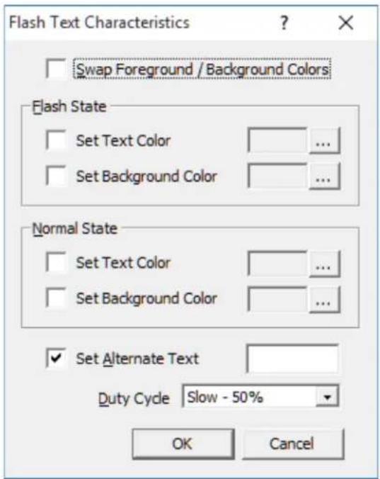
FIGURE 28. Flash Text Characteristics Window
Swap Foreground / Background Colors Check Box
The Swap Foreground / Background Colors check box indicates the foreground color swaps with the background color creating a blinking effect on the keypanel display.
Flash State Group Box
The Flash State group box is used to assign text and background colors used when a tally state is flashing.
Set Text Color Check Box
The Set Text Color check box activates the Selected Color cell and Browse button. This means you can modify the color of the Text displayed.
Selected Color Cell and Ellipsis Button
The Selected Color cell displays the currently selected color of the text.
The Ellipsis button opens the Select Color window where you can assign a different color to the text.
Set Background Color Check Box
The Set Background Color check box activates the Selected Color cell and Browse button. This means you can modify the color of the Background displayed.
Selected Color Cell and Ellipsis Button
The Selected Color cell displays the currently selected color of the background.
The Ellipsis button opens the Select Color window where you can assign a different color to the background.
Normal State Group Box
The Normal State group box is used when the tally is active and is not in the flash state. If there is no tally active, then the colors are whatever is defined for the assignment in the intercom.
Set Text Color Check Box
The Set Text Color check box activates the Selected Color cell and Browse button. This means you can modify the color of the Text displayed.
Selected Color Cell and Ellipsis Button
The Selected Color cell displays the currently selected color of the text.
The Ellipsis button opens the Select Color window where you can assign a different color to the text.
Set Background Color Check Box
The Set Background Color check box activates the Selected Color cell and Browse button. This means you can modify the color of the Background displayed.
Selected Color Cell and Ellipsis Button
The Selected Color cell displays the currently selected color of the background.
The Ellipsis button opens the Select Color window where you can assign a different color to the background.
Set Alternate Text Check Box and Entry Field
The Set Alternate Text check box and entry field is used to enter alternate text or characters that appears intermittently with the existing tally text.
This field can contain up to four characters.
Duty Cycle Drop Down Menu
The Duty Cycle drop down menu is used to select the rate the tally flashes.
Available options for this menu are:
On Solid There is no flash
Slow 25% The alternate text appears for 25% of the flash period (1/4 of a second), while the normal mode appears for 75% of the flash period (3/4 of a second)
Slow 50% The flash and normal mode appear for 50% of the flash period (1/2 second each)
Fast 50% The flash and the normal mode appear for 50% of the flash period in alternating pattern (1/4 second flash, 1/4 second normal mode, 1/4 second flash, 1/4 second normal mode)
Slow 75% The flash appears for 75% (3/4 second), while the existing text appears for 25% (1/4 of a second) of the flash period.
NOTE: The flash period is one second.
OK Button
The OK button is used to accept/apply the changes and close the window.
Cancel Button
The Cancel button is used to reject the changes and close the window.
Show Icon Characteristics Window
The Show Icon Characteristics window is used to configure which icon to display during a tally event and the rate at which it flashes during the event.

FIGURE 29. Show Icon Characteristic Window
Icon Drop Down Menu
The Icon drop down menu is used to select the icon you desire. See Table 7 on page 91.
Duty Cycle Drop Down Menu
The Duty Cycle drop down menu is used to select the rate the icon flashes.
Available options for this menu are:
On Solid There is no flash
Slow 25% The alternate text appears for 25% of the flash period (1/4 of a second), while the normal mode appears for 75% of the flash period (3/4 of a second)
Slow 50% The flash and normal mode appear for 50% of the flash period (1/2 second each)
Fast 50% The flash and the normal mode appear for 50% of the flash period in alternating pattern (1/4 second flash, 1/4 second normal mode, 1/4 second flash, 1/4 second normal mode)
Fast 75% The flash appears for 75% (3/4 second), while the existing text appears for 25% (1/4 of a second) of the flash period
Animate 4-frame animation, each frame displays for 25% of the flash period.
NOTE: The flash period is one second.
OK Button
The OK button is used to accept/apply the changes and close the window.
Cancel Button
The Cancel button is used to reject the changes and close the window.
Enhanced Tally Icons
Enhanced Tally Icons, shown in Table 7, are used to visually alert keypanel users of different events occurring on the keypanel and in the Matrix system. The keypanel ships with these icons built-in by default. However, you can download new icons to the panel using AZedit.
NOTE: These icons are the default icons sent with the keypanel. These icons can be used for any purpose. Not all the icons are used as defaults. The descriptions in Table 7 are just suggested uses.
TABLE 7. Tally Icon Descriptions
| Icon | Icon Name | Description |
 | Target Incoming Call (animation supported) – A call is coming into the keypanel and the animation toggles the target every half second. Extended Call (animation not supported)– The extended call tally is generated when the key is on for a predetermined amount of time. In English intercoms, five seconds pass before the tally begins, while in Japanese intercoms, two seconds must pass | |
 | Red Star Trunk In-Use (animation not supported) Trunk Busy (animation supported) – The trunk is busy. The animation toggles the star on/off every quarter of a second. | |
 | Black Star IFB/ISO In Use (animation not supported) IFB/ISO Busy (animated) - The IFB/ISO is busy. The animation rotates the start on/off every quarter of a second. | |
| [8BY4] | Orange Wave | PL In-Use (animation not supported) |
| [X774] | Gray Gear General In-Use (animation not supported) - Used in Japanese intercoms. This tally is used to show when other keypanels are doing an action on the keypanel. In a Japanese intercom, if your panel is in-use (i.e., you turn on a talk key to anybody), and I have your assignment on my keypanel, the assignment on my keypanel displays the General In-Use tally, even though we are not talking to each other. | |
 | Red Phone TIF Ringing (animation supported) - The handset vibrates in the animation. | |
 | Yellow Phone | TIF Offhook (animation supported) - The TIF key is active. The phone slow flashes every half second. |
| [2C22] | Exclamation | Available for UPL Tally (animation supported) - The animation is a slow flash every half second. |
| [BHS4] | Heart Available for UPL Tally (animation supported) - The animation is a slow flash every half second. | |
 | Question Available for UPL Tally (animation supported) - The animation is a slow flash every half second. | |
| [G642] | Flag Available for UPL Tally (animation supported) - The animation is a slow flash every half second. | |
 | Person | Available for UPL Tally (animation supported) - The animation is a slow flash every half second. |
 | Link | Available for UPL Tally (animation supported) - The animation is a slow flash every half second. |
 | Car | Available for UPL Tally (animation supported) - The animation is a slow flash every half second. |
| [BWS8] | Lightening Bolt | Available for UPL Tally (animation supported) - The animation is a slow flash every half second. |
TABLE 7. Tally Icon Descriptions
| Icon | Icon Name Description |
 | House Available for UPL Tally (animation supported) - The animation is a slow flash every half second. |
 | Handset Available for UPL Tally (animation supported) - The animation is a slow flash every half second. |
 | Lock Available for UPL Tally (animation not supported) |
 | Speaker Available for UPL Tally (animation supported) - The animation is a slow flash every half second. |
 | Play Available for UPL Tally (animation supported) - The animation is a slow flash every half second. |
 | Message Available for UPL Tally (animation supported) - The animation is a slow flash every half second. |
 | Red Circle Available for UPL Tally (animation supported) - The animation is a slow flash every half second. |
Panel Tally
Panel Tally is used to notify a keypanel user of an event not specifically belonging to a key; for example, a blinking icon appears when a newscast is on air. Panel tallies are controlled through the use of UPL statements. Multiple UPL statements can be configured, but only one icon displays at a time. Lower numbered icons take priority.
NOTE: The keypanel ships with these icons built-in by default. However, you can download new icons to the panel using AZedit.
Available panel tally icons are:
Suggested Use Suggested Use

Alarm, Appointment, Event Favorite


Alarm, Chime, Notify Information


Target, Incoming Negative


Appointment, Event On Air


On-Air, Live Warning, Alarm, Alert


Error Sports


Warning Alarm, Chime, Notify


Positive, Notify Good, Affirmative

Create and Download New Icons
IMPORTANT: AZedit 5.2.0 and later include the panel and key icon files.
Key Overlay Icons
An Overlay Icon is an icon that lies on top of a key in the keypanel display screen of the keypanel. There are 32 icons shipped with the keypanel and supported. However, you can create your own icons.
A single icon is 16 x 16 pixels. AZedit uses bitmaps rather than icon (.ico) files. This is so users can use the system tool Paint to create their icons, instead of a specialized icon editor. 32 icons are supported for key overlays, so the bitmap must be 512 pixels wide (16 pixels x 32 icons). Animation of icons is also supported (4 frames), so the bitmap is 64 pixels tall (16 pixel icons x 4 rows of icons), where each column of icons contains four images for animation of the icon, and each row of icons represent stage 1–4 of the animation for each icon. Figure 30, shows a 512x64 pixel bitmap (a table of 32x4 icons).
IMPORTANT:
The following icons are built into the panel. The file is shipped with AZedit so it can be easily copied and modified by the user to create their own icons.
By downloading you own icons, you are replacing the ones built into the keypanel. Retain a copy of the icons shipped with AZedit, in case you want to reuse the default icons.

FIGURE 30. 512 x 64 pixel bitmap of key overlay icons
AZedit accepts a bitmap of narrower width (as long as it is a multiple of 16). This is done by extending the bitmap to 512 pixels by adding white space horizontally. Vertically, the bitmap needs to be 16 pixels high, and then repeat the image 3 more times to make it 64 pixels high. Repeating the icon four times, indicates there is no animation. You can also create a bitmap 32 pixels high (two frames per icon) and repeat the image once to make 64 pixels high (so there would be two frames of animation repeated).
The pixel color in the top left corner of each 16x16 pixel cell is treated as a transparent color. All pixels of the same color in each 16x16 pixel cell will not be rendered when the icon is drawn on the keypanel. For example, in Figure 30, magenta is used as the transparent color in all icon cells. If magenta was not treated as transparent, all of the icons above would display as an icon in a magenta square.
Panel Icons
For Panel Icons, the icons are 32x32 pixels. 16 panel icons are supported, as well as 4-frame animation, so the bitmap must be 512x128, producing a table of 16x4 icons (each icon 32x32 pixels), see Figure 31. Like key icons, AZedit accepts a narrower image (as long as it is a multiple of 32) and uses white space to fill in the missing pixels. Shorter images are supported (as long as the image is either 32 or 64 pixels tall) and are replicated (3 times, or once) to get an image measuring 128 pixels tall.
IMPORTANT:
The following icons are built into the panel. The file is shipped with AZedit so it can be easily copied and modified by the user to create their own icons.
By downloading you own icons, you are replacing the ones built into the keypanel. Retain a copy of the icons shipped with AZedit, in case you want to reuse the default icons
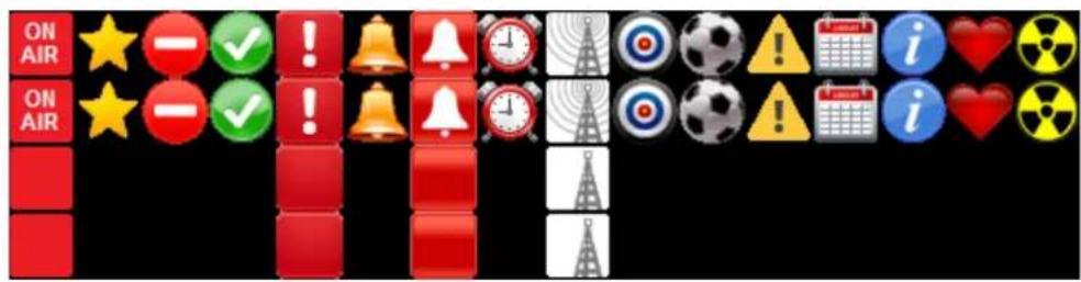
Keypanel Mirroring (Control Package Only)
Keypanel Mirroring allows a licensed keypanel (licensed as a supervisor) to take control of a target keypanel. All KP-Series keypanels can be the target of mirroring, whereas only licensed keypanels can be the supervisor of a target keypanel. By default, Keypanel Mirroring is disabled. You must enable a panel to be a mirror supervisor in AZedit. This allows any licensed keypanel to initiate a mirroring operation on a local target.
IMPORTANT: Mirroring is not supported between trunked intercoms.
Keypanel Mirroring operates in real-time, meaning when a supervisor keypanel initiates a mirroring operation almost all aspects of the target keypanel functionality are accessible. Once the configuration file is transferred from the target to the supervisor keypanel, the supervisor keypanel looks and behaves like the target. Turning keys on/off, adjusting key volumes or panel volumes on either the target or supervisor keypanel is seen immediately on the other keypanel.
NOTE: If a KP-5032 mirrors a KP-4016 or a DKP-4016, it does not take on the 1RU or desktop aspects.
On the target keypanel, the keypad is locked out, preventing the target keypanel from entering the menu. Any changes to the configuration made by the supervisor keypanel are immediately transferred to the target keypanel.
| IMPORTANT: | The Supervisor keypanel can change settings for features the Target is licensed for, even if the Supervisor is not licensed for those same features. Compression ratios, additional noise gate settings, and the 5-band equalizer settings are all available in the Supervisor (even if it is not licensed for these features) as long as the Target panel is licensed for them. For example, if the target keypanel supports a 5-band EQ and the supervisor keypanel does not, the supervisor keypanel is able to change the EQ settings. |
In AZedit, if a keypanel is a mirror Supervisor or Target, an icon is shown in the Port Status area in the Keypanel View.
 | Supervisor icon The | Supervisor icon signifies the keypanel is mirroring another keypanel and can make changes to the other keypanel, known as a Target. For more information, see “Service Menu, Mirror (Control Package Only)” on page 248. |
 | Target icon The Target | Target icon signifies the keypanel is being mirrored by another keypanel, known as a Supervisor. This keypanel is being remotely controlled by the Supervisor. For more information, see “Service Menu, Mirror (Control Package Only)” on page 248. |
| ****These icons also appear on the keypanels involved in the mirror operation. | ||
IMPORTANT: If you make changes, including real time changes, to a Target Keypanel using AZedit, those changes are also seen on the Supervisor Keypanel. However, if you make changes, including real-time changes, to a Supervisor Keypanel using AZedit, those changes are made to the Supervisor's saved configuration, but are not implemented until the Supervisor Keypanel exits Mirroring and returns to normal operation.
To disable mirroring on a keypanel, do the following:
- In AZedit, click the Edit button.

The Keypanel/Port Configuration window appears.

- Click the Advanced Tab.
- Clear the Enable Keypanel Mirroring check box.
- Send the changes to the intercom.
To enable mirroring on a keypanel, do the following:
- In AZedit, click the Edit button.

The Keypanel/Port Configuration window appears.
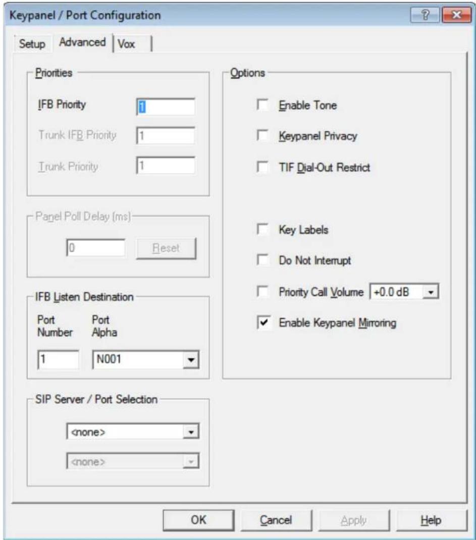
- Click the Advanced Tab.
- Select the Enable Keypanel Mirroring check box.
- Send changes to the intercom.
To take control of a target keypanel, do the following:
IMPORTANT: When you enter the Mirror menu looking for a target panel to Mirror, you can only see panels that are locally scroll enabled (ie. if they aren't in your scroll list, you won't be able to mirror them).
- On the keypanel, starting at the Service menu, select Mirror.
- Press the SEL button.
A list of available target keypanels appear in the panel display. - Using the arrow buttons, scroll to the target keypanel.
- Press the SEL button.
The Supervisor keypanel updates and displays the target keypanel's image.
To exit Mirror mode on the keypanel, do the following:
- On the keypanel, starting at the Service menu, select Mirror.
- Press the SEL button.
The alpha of the target and Exit appear in the panel display. - Using the arrow buttons or Aux Volume shaft encoder, select Exit.
- Press the SEL button.
The mirroring target and supervisor icons disappear and keypanels go back to normal operation.
Real-Time Control in AZedit (Control Package Only)
Real-Time Control allows you to make real-time (immediately applied) changes to intercom and keypanel volume controls as well as muting keypanel microphones, switching headset focus, setting AFK, and enabling tone at selected keypanel ports.
Intercom Volume Controls
Intercom Volume Controls are used to adjust Crosspoint Listen, Party Line Listen, Port Input Gain, and Port Output Gain. Adjustments to these different volumes can be done in real-time or modified and sent to the intercom at a later time.
There are two ways to adjust the intercom volume controls;
• via the Port Volumes window
- opening the individual gain adjustment screens
By default, intercom volumes are set at +0.0dB.
The range for Crosspoint Listen and Party Line Listen is Mute, -80dB to +6dB. The range for the Port Input Gain and the Port Output Gain is -20dB to +20dB.
To enable real-time intercom volume adjustments, do the following:
- On the KP/Ports screen, click the Port Volumes icon.
The Port Volumes window appears.
OR
Right-click in the keypanel key field and select Change Volume.
The Port Volumes window appears.

- In the lower left-hand corner of the window, select the Enable Real Time Changes check box. The Intercom is real-time enabled.
IMPORTANT:
When changes have been made to the intercom volumes but have not been sent to the intercom and the Enable Real Time Changes check box is selected, a warning message appears (Figure 32).
- Click Yes to abort all changes to volumes for this port.
- Click No to leave the changes (but don't send them).
- Click Cancel to disable real-time changes.

FIGURE 32. Real Time Warning Message
To adjust the intercom volumes via the Port Volumes window, do the following:
- On the KP/Ports screen, click the Port Volumes icon.
The Port Volumes window appears.
OR
Right-click in the keypanel key field and select Change Volume.
The Port Volumes window appears.

- Verify the Intercom page is selected.
- In the combo box drop down menu, select the alpha you want to adjust (i.e., 1).
- From the combo box drop down menu, select the party line you want to adjust (i.e., PL01).
- Using the volume sliders, make adjustments to the volume gain.
NOTE: If Real-Time is not enabled, send the changes to the intercom.
Keypanel Volume Controls
Keypanel Volume Controls are used to modify volumes on keypanels without physically going to the keypanel to do so. Unlike Intercom Volume Controls, Keypanel Volume Controls are always changed in real-time. However, the real-time controls are only enabled if the keypanel supports it (licensed). Adjustable keypanel volumes include Speaker, Headset, Matrix In minimum, and Aux In minimum.
By default keypanel volumes are +0.0dB.
The range for Speaker, Headset, Matrix In, and Aux In volumes is: Mute, -48dB to +10dB.
To adjust keypanel volumes, do the following:
- On the KP/Ports screen, click the Port Volumes icon.
The Port Volumes window appears.
OR
Right-click in the keypanel key and select Change Volume.
The Port Volumes window appears.

NOTE: When using ganged volumes, four sliders appear in both the Speaker and Headset group boxes. See Figure 33. For more information on Ganged Volumes, see “Audio Options Menu, Ganged Vols” on page 201.
- From the drop down menu under Speaker, select Front or Rear. OR
From the drop down menu under Headset, select Front or Rear.
OR
From the drop down menu under Aux In, select OMNEO 1-8 or Aux 1-2.
IMPORTANT: OMNEO 1 can be an Aux channel if the keypanel is connected to the intercom via AIO.
-
From the Ganged Volume Adjust Mode drop down menu, select Disappearing Offset or Fixed Offset.
-
Using the volume sliders, adjust the keypanel volume.
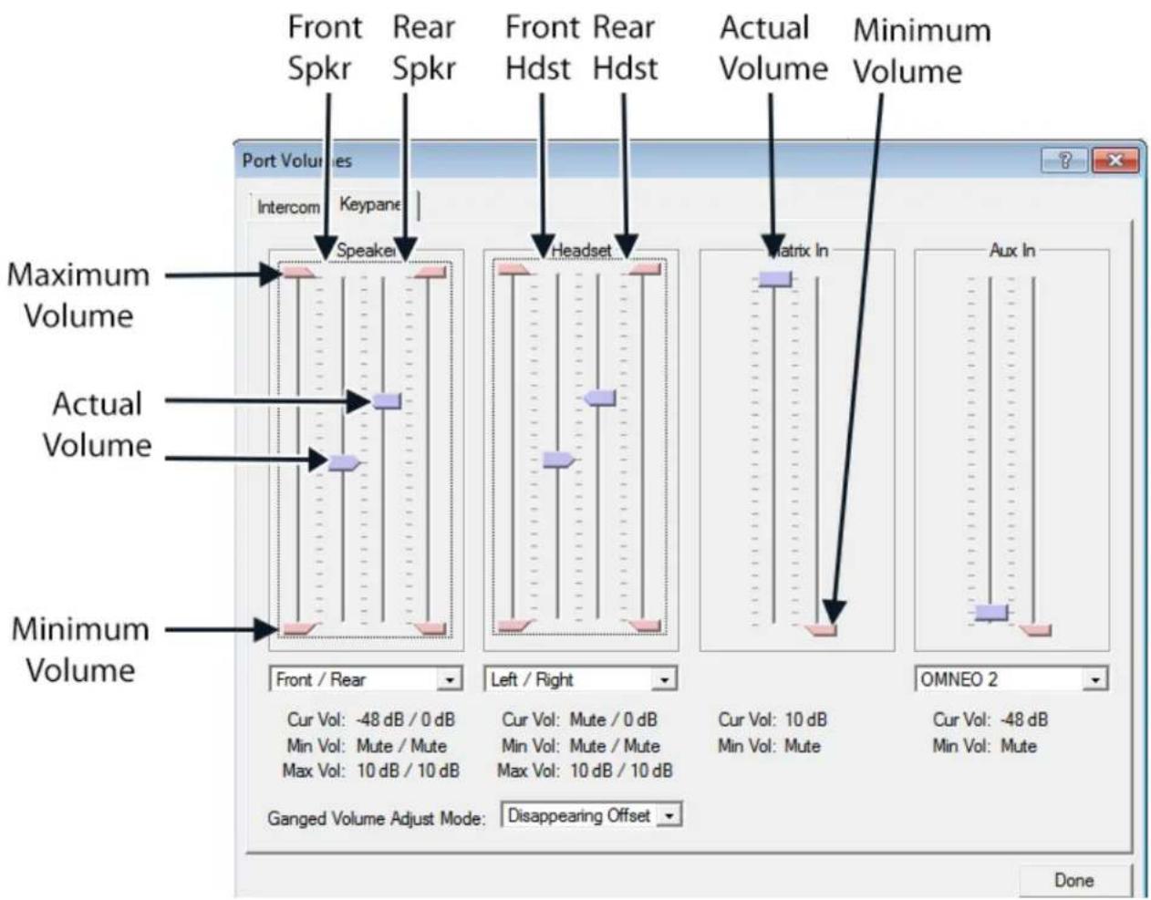
FIGURE 33. When Ganged Volumes are Configured
Mic Mute
Mic Mute is used to remotely enable or disable a selected keypanel (port) microphone from AZedit. This feature requires the Control Package license.
IMPORTANT: When the Mic is muted, the mic mute icon flashes on the keypanel.
When Tone is enabled, the mic mute icon is static on the keypanel.
To mute a microphone from AZedit, do the following:
- From the Port/Alpha group box, select the port/alpha of the microphone which you want to mute.
- Right-click in the Port Status group box.
A pop-up menu appears.

- From the pop-up menu, select Mute Microphone.
A muted mic icon appears in the Port Status group box and a flashing Mic Mute icon appears in the keypanel display screen.
To unmute a microphone that is muted from AZedit, do the following:
- From the Port/Alpha group box, select the port/alpha of the microphone you want to un-mute.
- Right-click in the Port Status group box.
A pop-up menu appears.

- From the pop-up menu, select Un-mute Microphone.
The muted mic icon disappears in the Port Status group box and the flashing Mic Mute icon stops flashing in the keypanel display screen.
Headset Transfer
Headset Transfer is used to switch between headset and speaker on a selected keypanel/port remotely from AZedit. This feature requires the Control Package license.
To switch to headset mode on the keypanel from AZedit, do the following:
- From the Port/Alpha group box, select the keypanel port/alpha of the keypanel you want to switch to headset mode.
- Right-click in the Port Status group box.
A pop-up menu appears.

- From the pop-up menu, select Switch to headset mode.
A headset icon appears in the Port Status group box and appears in the keypanel display screen. The keypanel is in headset mode.
To switch to speaker mode on the keypanel from AZedit, do the following:
- From the Port/Alpha group box, select the port/alpha of the keypanel you want to switch to speaker mode.
- Right-click in the Port Status group box.
A pop-up menu appears.

- From the pop-up menu, select Switch to speaker mode.
The headset icon disappears and the speaker icon appears in the Port Status group box and appears in the keypanel display screen. The keypanel is in speaker mode.
AFK Mode
AFK Mode is used to enable and disable AFK (Away From Keypanel) on a keypanel/port remotely from AZedit. This feature requires the Control Package license.
For more information on AFK, see "Voice Messaging (Audio Package Only)" on page 68.
To enter AFK mode on a keypanel remotely from AZedit, do the following:
- From the Port/Alpha group box, select the keypanel port/alpha you want to enable AFK.
- Right-click in the Port Status group box.
A pop-up menu appears.

- From the pop-up menu, select Enter AFK mode.
The AFK icon in the Port Status group box and in the keypanel display screen.
To exit AFK mode on a keypanel remotely from AZedit, do the following:
- From the Port/Alpha group box, select the keypanel port/alpha you want to exit AFK mode.
- Right-click in the Port Status group box.
A pop-up menu appears.

- From the pop-up menu, select Exit AFK mode.
The AFK icon disappears from the Port Status group box and from the keypanel display screen.
Enable Tone
Enable Tone is used to enable and disable the tone generator on the selected keypanel/port from AZedit. This feature requires the Control Package license
IMPORTANT: When Tone is enabled, the mic mute icon is static on the keypanel. When the Mic is muted, the mic mute icon flashes on the keypanel.
To enable tone on the keypanel remotely from AZedit, do the following:
- From the Port/Alpha group box, select the port/alpha you want to enable tone.
- Right-click in the Port Status group box.
A pop-up menu appears.

- From the pop-up menu, select Enable Tone.
An enable tone icon appears in the Port Status group box and appears in the keypanel display screen. The keypanel sends a tone to the intercom.
To disable tone on the keypanel remotely from AZedit, do the following:
- From the Port/Alpha group box, select the port/alpha you want to disable tone.
- Right-click in the Port Status group box.
A pop-up menu appears.
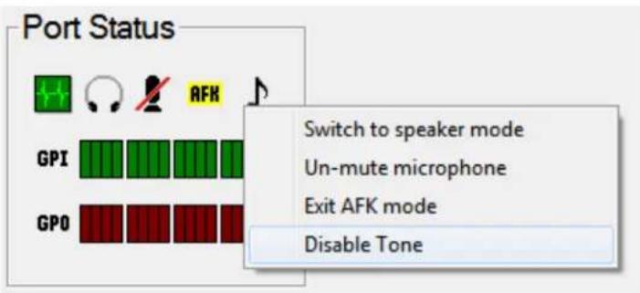
- From the pop-up menu, select Disable Tone.
The enable tone icon disappears from the Port Status group box and disappears from the keypanel display screen.
Keypanel Configuration (Control Package Only)
The Keypanel Configuration window gives you the ability to upload a keypanel's configuration file to AZedit, make changes to the configuration, save the configuration, and send it back to the keypanel.
You can also send one configuration file to multiple keypanels from AZedit.
Upload a Configuration File from a Keypanel
Uploading a configuration file from a keypanel can be used to modify an existing keypanel configuration file and/or save it.
To upload a keypanel's configuration file to AZedit, do the following:
- From the Port Alpha group box, enter the port number.
OR
From the Alpha drop down menu, select the Alpha of the keypanel/port you want to configure.
- Click the Keypanel Configuration icon.

The Keypanel Configuration window appears.
-
Make modifications to the configuration file.
-
Click Apply to apply the modifications to the keypanel
Load Button
The Load button is used to import or merge a saved configuration file on top of the settings you are viewing.the Miscellaneous|Keypanel Configuration menu item allows you to Open a saved configuration file and edit it, which is different from a Load.
OPEN Opens a saved file, which can be modified and re-saved, but not Applied
LOAD Load overlays the contents of a file on top of either a file that you had previously opened, or the current (uploaded) settings for a keypanel. Only settings that existed before the Load can be affected by the Load (ie. you can't add new parameter settings to a file that you opened, or the current config of a keypanel). Once the loaded file is overlaid, you can edit any setting and then either save the file (if you started by opening a file) or apply the changes (if you started by uploading the current settings for a keypanel).
To open a configuration file in AZedit, do the following:
- From the System menu, select Miscellaneous|Keypanel Configuration.
A network folder appears.
-
Navigate to and select the keypanel configuration file (.kpc file) you want to load into AZedit.
-
Click Open.
The Keypanel Configuration window appears.
-
Make the necessary modifications to the file.
-
Click the Save All or Save Changes.
Save All Button
The Save All button is used to save the entire configuration file.
To perform a save all, do the following
- Make modifications to the configuration file, as desired.
- Click the Save All button.
The Save Keypanel Configuration window appears. - Enter a unique file name and make note of where its saved on the network.
- Click OK.
The configuration file is saved.
Save Changes Button
The Save Changes button is used to save only modifications in the configuration file.
- Make modifications to the configuration file, as desired.
- Click the Save Changes button.
The Save Keypanel Configuration window appears. - Enter a unique file name and make note of where its saved on the network.
- Click OK.
The changes are saved.
Apply Button
The Apply button is used to download modifications made to the keypanel configuration directly to the keypanel. The Apply button is only active if you uploaded the current configuration from a keypanel. If you opened a configuration file using the System|Miscellaneous menu, the Apply button is disabled.
IMPORTANT: Applying changes to a keypanel configuration causes the keypanel to do a Save Config, storing the settings locally.
To apply changes to the keypanel, do the following:
- Make modifications to the configuration file, as desired.
- Click the Apply button.
The modifications are sent directly to the keypanel.
Download a Configuration File to Multiple Keypanels
IMPORTANT: Downloading a configuration causes the keypanel to do a Save Config, storing the settings locally.
To download a configuration file to one or more keypanels, do the following:
- From the Status menu, select Port.
The Port Status screen appears.
OR
From the Status menu, select Software Versions|Keypanels.
The Keypanel Version Information screen appears. - Select the port(s) or keypanel(s) you want to download the configuration file to.
-
Right-click the selected port(s) or keypanel(s).
A popup menu appears. -
From the popup menu, select Download Keypanel Configuration... A network folder appears.
- Navigate to where the keypanel configuration file is kept.
- Select the file and click Open. The Download Keypanel Configuration window appears.
- Click Begin Download.
Panel Options Page

FIGURE 34. Keypanel Configuration – Panel Options
LCP Encoder Assignments Group Box
The LCP Encoder Assignments group box is used to assign volume control functions to the LCP shaft encoders remotely from AZedit. For a description of the selections available, see “Audio Options, Menu, LCP 16 CLD” on page 206.
NOTE: OMNEO 3 through OMNEO 8 only appears when the Audio Package is purchased, otherwise, they do not display.

TABLE 8. Panel Options Page – LCP Encoder Assignments
To assign inputs and outputs to the LCP, do the following:
From the panel drop down menu, select the volume function you want to assign.
Panel Swap Group Box
The Panel Swap group box is used to give users the ability to quickly and easily change a group of keypanel assignments on the keypanel. This is done through the use of virtual expansion panels. Panel swap differs from changing setup pages because the keys can stay active even when they are no longer visible on the main panel. For a description of the selections available, see “Key Options Menu, Panel Swap” on page 230.
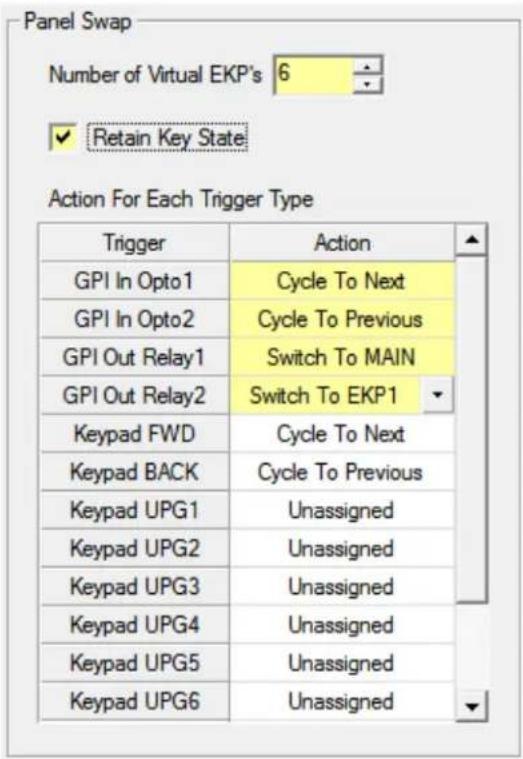
FIGURE 35. Panel Options Page – Panel Swap Group Box
To configure panel swap, do the following:
- Using the Number of Virtual EKPs scroll box, enter the number of virtual EKPs.
- Select the Retain Key State check box to retain the key states when the keys are not visible (for example, when the page the keys are located is not being displayed).
- From the Action column next to the key you want to configure, select the appropriate panel swap action.
UPG Key Definition Group Box
The UPG Key Definition group box is used to assign different inputs and outputs to the UPG keys on the keypanel remotely from AZedit. For more information on UPG Buttons, see "User Programmable Buttons" on page 73.
IMPORTANT: Menu Assignments cannot be created from this screen; however, they can be removed.

FIGURE 36. Panel Options Page – UPG Key Definition Group Box
To configure a UPG key, do the following:
- From the Operation column next to the UPG you want to configure, select the operation you want.
- From the GPIO Output column drop down menu, select the output action desired.
Quick-Assign Listen Assignments Group Box
The Quick Assign Listen Assignments group box is used to assign listen assignment to point-to-point, party line, special list, and group key assignments. Note, this does not change existing keypanel assignments, it only affects assignments you make in the future using the Quick Assign function. For more information on listen assignments, see “Operation of Intercom Keys with Auto Functions” on page 58.

FIGURE 37. Panel Options Page – Quick-Assign Listen Assignments Group Box
To assign a listen assignment, do the following:
From the listen assignment column drop down menu, select the desired listen assignment for the function type.
Panel Mode Group Box
The Panel Mode group box is used to configure the keypanel's operating mode and alpha display.
Intercom Mode is used to select the type of firmware you have in your intercom so the keypanel can display alphas in the correct font/language and modify the behavior of some functions to match the intercom behavior.
NOTE: Standard mode is the default and should be used in most cases. Alternate mode is primarily used for intercoms running Japanese firmware.
The Alpha Size is the number of alpha characters shown in the display panel window.
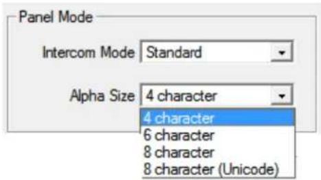
FIGURE 38. Panel Options Page – Panel Mode Group Box
IMPORTANT: The keypanel saves its configuration and reboots if the panel mode is changed.
To configure panel mode, do the following:
- From the Intercom Mode drop down menu, select the Standard or Alternate.
- From the Alpha Size drop down menu, select 4 character, 6 character, 8 character, or 8 character (Unicode).
Miscellaneous Group Box
The Miscellaneous group box is used to configure SEL key functions and Page Change Mode.
The SEL Key function allows the user to choose what function the SEL key performs when not in menu mode. For a description of the selections available, see “SEL Key” on page 245.
Page Change is used to select whether you are allowed to change setup pages while talk keys are active. By default, in Standard Intercom Mode, page changes are allowed when talk keys are active. However, the default in Alternate Intercom Mode does not allow page changes to occur when talk keys are active. For a description of the selections available, see "Service Menu, Page Change" on page 252.

FIGURE 39. Panel Options Page – Miscellaneous Group Box
Snoop Tally Group Box
The Snoop Tally group box is used to configure the type and length of the snoop tally, when enabled. The snoop tally indicates to keypanel users somebody is listening to them.
For a description of the duration selections available, see "Service Menu, Snoop Tally" on page 256.
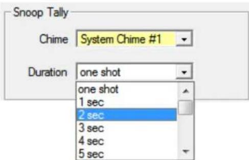
FIGURE 40. Panel Options Page – Snoop Tally Group Box
To configure the snoop tally, do the following:
- From the Chime drop down menu, select the chime you want to use.
- From the Duration drop down menu, select the duration you want the chime to sound.
GPI Inputs Assignments Group Box
The GPI Inputs Assignment group box is used to configure GPI inputs on the keypanel. Inputs can be assigned to activate intercom keys (including group master keys).
Further configuration can be done to allow GPI Inputs to track the state of the Output. For example, if an output is activated (and is being tracked by an input), the input is also activated. This feature allows GPIO Outputs to control Talk Key or Key Group activation.
In addition to tracking, you can also configure the way an Input GPIO Key Group is configured. By default, when a key group is activated, the keys are forced on until the key group is deactivated. This is referred to as Level Mode. Alternatively, you can configure the key group to Edge Mode. This option turns on keys in a key group when the group is activated, but allows the user to turn off individual keys even if the key group is still active.
For a description of the selections available, see "Service Menu, Local GPIO" on page 246.
| Input | Assign To | Track | Key / Group | Key Mode |
| Opto 1 | Key Group | Output | Group 1 | Edge |
| Opto 2 | Talk Key | Input | Key 1 |
FIGURE 41. Panel Options Page – GPI Input Assignments Group Box
To configure the GPI Input Assignments, do the following:
- From the Assign To column drop down menu, select whether the input is assigned to a talk key or a key group.
- From the Track column drop down menu, select the whether the input should track the output.
- From the Key/Group column drop down menu, select the key or group the input is configured to.
- From the Key Mode drop down menu, select the behavior of keys in a group when they are activated.
GPI Output Assignments Group Box
The GPI Output Assignments group box is used to assign Relays 1 and 2 to keys on the keypanel.

FIGURE 42. Panel Options Page – GPI Output Assignments Group Box
To configure the GPI Output Assignments, do the following:
From the Key/UPG column drop down menu next to the relay you want, select the key or UPG you want to assign the relay.
Footswitch Mode Group Box
The Footswitch Mode group box is used to enable the footswitch and configure the behavior of keys upon release. For more information, see "Service Menu, Footswitch" on page 240.
To cable for a Footswitch, see "Footswitch Cabling" on page 36.
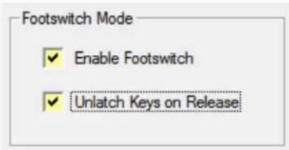
FIGURE 43. Panel Options Page – Footswitch Mode Group Box
To configure the enable and configure the footswitch, do the following:
- Select the Enable Footswitch check box.
- Select the Unlatch Keys on Release check box if you want the latched talk keys to become unlatched when the footswitch is released
Display Page
The Display Page is used to configure the keypanel and expansion panel displays, including backlight colors, percentage of brightness, screen saver settings, key display options, and panel display options.

FIGURE 44. Keypanel Configuration – Display Page
Keypad Backlight Group Box
The Keypad Backlight group box is used to select the color and brightness of the keypad backlight LEDs at various usage states and to configure the keypad mode.
For more information on the keypad backlight options and descriptions, see "Service Menu, Keypad" on page 243.
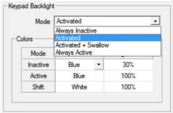
FIGURE 45. Display Page – Keypad Backlight Group Box
To configure the keypad backlight, do the following:
- From the Mode drop down menu, select how the keypad backlight is activated whether the first keypress is processed or swallowed.
- From the Color column drop down menu, select either Blue or White.
- From the Brightness column drop down menu, select the brightness percentage you desire.
Key Display Options Group Box
The Key Display Options group box is used to configure the keypanel keys to show key crosspoint gains, show listen assignments, or show the matrix for each key assignment. For more information on the available options, see "Service Menu, Key View" on page 242
IMPORTANT: Show Listen and Show Matrix are mutually exclusive options. Only one of these options may be enabled at a time
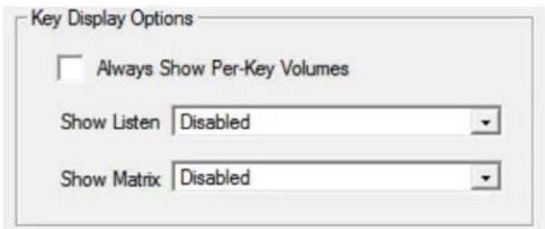
FIGURE 46. Display Page – Key Display Options Group Box
To configure the keypanel display, do the following:
-
Select the Always Show Per-Key Volumes check box if you want to display the crosspoint gain for each key on the keypanel.
-
From the Show Listen drop down menu, select Disabled, Enabled, or Enabled-Suppress Auto-Function.
-
From the Show Matrix drop down menu, select Disabled, Enabled, or Enabled-Suppress Local.
Panel Display Options Group Box
The Panel Display Options group box is used to enable the menu context, display speaker volume and to switch the display to emulate a KP-32 keypanel. For more information on the available settings, see "Service Menu, Key View" on page 242.
NOTE: Menu context is not available on the KP-4016.
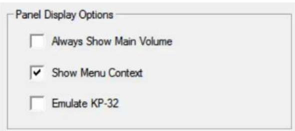
FIGURE 47. Display Page – Panel Display Options Group Box
To configure the panel display options, do the following:
- Select the Always Show Main Volume check box.
- Select the Menu Context check box to display the navigational menu above the keypanel keys.
- Select the Emulate KP-32 check box to convert the keypanel display to look like a KP-32 Classic keypanel.
LCD Backlight Group Box
The LCD Backlight group box allows you to set the brightness of the panel display of all keypanels and any expansion panel connected to the main keypanel.
| Panel | Left LCD | Right LCD |
| Main | 65% | 65% |
| EKP1 | 65% | 65% |
| EKP2 | 65% | 65% |
| EKP3 | 65% | 65% |
| EKP4 | 65% | 65% |
| EKP5 | 65% | 65% |
| EKP6 | 65% | 65% |
| EKP7 | 65% | 65% |
FIGURE 48. Display Page – LCD Backlight Group Box
To configure the LCD Backlight, do the following:
- From the Left LCD column spin box next to the display you want to set, select the brightness percentage.
- From the Right LCD column spin box menu next to the display you want to set, select the brightness percentage.
Screen Saver Group Box
The Screen Saver group box is used to configure the screen saver. For more information on the available settings, see "Service Menu, Scrn Saver" on page 254.

FIGURE 49. Display Page – Screen Saver Group Box
To configure the screen saver, do the following:
- From the Activation Delay drop down menu, select the amount of inactive time before the screen saver activates on the keypanel.
- From the Display Mode drop down menu, select the display mode for the screen saver.
- From the Movement drop down menu, select the type of movement the screen saver should display.
- From the Dimming Delay drop down menu, select the amount of time to pass before the display dims.
- Using the scroll box, scroll to the percentage the display should dim when dimming delay time is met.
Key Options Page
The Key Options Page is used to configure many of the keypanel operation options, such as auto dial functions, chime keys and duration, exclusive keys, key group assignments, solo key configuration, latching options, button lock, and tally operation.
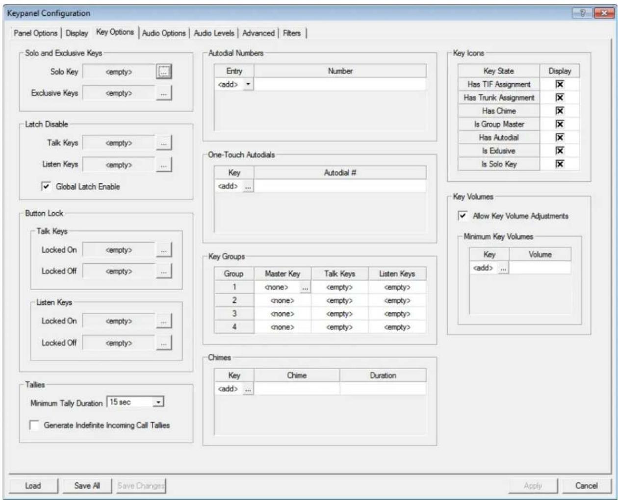
FIGURE 50. Keypanel Configuration – Key Options Page
Solo And Exclusive Keys Group Box
The Solo and Exclusive Keys group box is used to configure solo and exclusive keys. For a description of a solo key, see "Key Options Menu, Solo" on page 233. For a description of an exclusive key, see "Key Options Menu, Exclusive" on page 225.
NOTE: You can assign only one solo key per keypanel.

FIGURE 51. Key Options Page – Solo and Exclusive Keys Group Box
To configure a solo key, do the following:
- Click the Solo key browse button
The Key Selection window opens.
| Row | Page | 1 | 2 | 3 | 4 | 5 | 6 | 7 | 8 | 9 | 10 | 11 | 12 | 13 | 14 |
| 1 | 1 | ||||||||||||||
| 2 | |||||||||||||||
| 3 | |||||||||||||||
| 4 | |||||||||||||||
| 5 | |||||||||||||||
| 6 | |||||||||||||||
| 7 | |||||||||||||||
| 8 |
-
Select the check box which correlates to the keypanel key and page you want to assign the solo key.
-
Click OK.
The Key Selection window closes and the key number appears in the Solo Key field.
To configure the exclusive keys, do the following:
- Click the Exclusive key browse button

The Key Selection window opens.
| Row | Page | 1 | 2 | 3 | 4 | 5 | 6 | 7 | 8 | 9 | 10 | 11 | 12 | 13 | 14 |
| 1 | 1 | ||||||||||||||
| 2 | |||||||||||||||
| 3 | |||||||||||||||
| 4 | |||||||||||||||
| 5 | |||||||||||||||
| 6 | |||||||||||||||
| 7 | |||||||||||||||
| 8 |
-
Select the check boxes which correlate to the keypanel keys and pages you want to assign an exclusive key.
-
Click OK.
The Key Selection window closes and the key number appears in the Solo Key field.
Latch Disable Group Box
The Latch Disable group box is used to enable or disable the keypanel key to stay on when pressed. For more information, see "Key Options Menu, Latching" on page 228.
NOTE: A key only latches if it is pressed and released within 0.5 seconds. Otherwise, the key always turns off when released.

FIGURE 52. Key Options Page—Latch Disable Group Box
To latch disable specific talk and listen keys, do the following:
- Click either the Talk or Listen browse button

The Key Selection window appears.
- Select the key you want to latch disable.
- Click OK.
To latch enable or disable all keys (global latch enable), do the following:
Select the Global Latch Enable check box.
OR
Clear the Global Latch Enable check box to globally disable latching.
Button Lock Group Box
The Button Lock group box is used to lock talk and/or listen keys in the on or off position. Each key may be independently locked on or off.

FIGURE 53. Key Options Page – Button Lock Group Box
To configure button lock on or off for talk keys, do the following:
- From the talk keys group box, click the browse button for Locked On OR
Click the browse button for Locked Off.
The Key Selection window opens.
| Row | Page | 1 | 2 | 3 | 4 | 5 | 6 | 7 | 8 | 9 | 10 | 11 | 12 | 13 | 14 |
| 1 | 1 | ||||||||||||||
| 2 | |||||||||||||||
| 3 | |||||||||||||||
| 4 | |||||||||||||||
| 5 | |||||||||||||||
| 6 | |||||||||||||||
| 7 | |||||||||||||||
| 8 |
- Select the check boxes of all the talk keys you want to configure as Locked On. OR
Select the check boxes of all the talk keys you want configure as Locked Off.
- Click OK.
The Key Selection window closes.
To configure button lock on or off for listen keys, do the following:
- From the listen keys group box, click the browse button for Locked On OR
Click the browse button for Locked Off.
The Key Selection window opens.
| Row | Page | 1 | 2 | 3 | 4 | 5 | 6 | 7 | 8 | 9 | 10 | 11 | 12 | 13 | 14 |
| 1 | 1 | ||||||||||||||
| 2 | |||||||||||||||
| 3 | |||||||||||||||
| 4 | |||||||||||||||
| 5 | |||||||||||||||
| 6 | |||||||||||||||
| 7 | |||||||||||||||
| 8 |
- Select the check boxes of all the listen keys you want to configure as Locked On. OR
Select the check boxes of all the listen keys you want configure as Locked Off.
- Click OK.
The Key Selection window closes.
Tallies Group Box
The Tallies group box is used to set the amount a time a blinking tally displays. For more information about Tallies, see “Key Options Menu, Tallies” on page 234.

FIGURE 54. Key Options Page – Tallies Group Box
To configure tally times, do the following:
From the Minimum Tally Duration drop down menu, select the duration of time you desire.
To generate indefinite call tallies, do the following:
Select the Generate Indefinite Incoming Call Tallies check box to set indefinite tallies for all calls.
Autodial Numbers Group Box
The Autodial Numbers group box is used to configure up to 100 autodial numbers. Autodial stores commonly used phone numbers in the auto dial list locally on the keypanel. You can also create a centralized auto dial list which is stored on the Master Controller and maintained through AZedit. For more information, see “Centralized Auto Dials” on page 261.

FIGURE 55. Key Options Page – Autodial Numbers Group Box
To add autodial numbers, do the following:
- From the Entry column drop down list, select the entry number for your autodial number. This number does not have to follow sequence.
- In the Number column field, enter the number you want to assign as an autodial.
NOTE: No spaces or dashes are allowed in the number entry field.
One-Touch Autodials Group Box
The One-Touch Autodials group box is used to assign autodial numbers to specific keypanel keys. One-Touch Auto Dials are configured using the locally stored numbers on the keypanel. Once a 1-Touch Auto Dial key is configured, pressing the configured key causes the TIF to go off-hook and auto dial the selected number.
IMPORTANT:
You must have existing autodial numbers before assigning them to a keypanel key. See "Autodial Numbers Group Box" on page 128.

FIGURE 56. Key Options Page – One-Touch Autodials Group Box
To add an autodial number, do the following:
- In the Key column field, click the browse button _. The Key Selection window appears.
| Row | Page | 1 | 2 | 3 | 4 | 5 | 6 | 7 | 8 | 9 | 10 | 11 | 12 | 13 | 14 |
| 1 | 1 | ||||||||||||||
| 2 | |||||||||||||||
| 3 | |||||||||||||||
| 4 | |||||||||||||||
| 5 | |||||||||||||||
| 6 | |||||||||||||||
| 7 | |||||||||||||||
| 8 |
-
Select the key (or keys) you want to assign autodial.
-
Click OK.
The Key Selection window closes.
- From the Autodial # column drop down menu, select the number you want to assign to the key.
Key Groups Group Box
The Key Groups group box is used to set up key groups. A key group allows a user to activate a group of keys by activating one key (the master key). When the master key is activated, all keys in the group become active.
You can create up to four key groups.
Key Groups
| Group | Master Key | Talk Keys | Listen Keys |
| 1 | 1 | 4, 5, 6 | 2, 11, 12, 13, ... |
| 2 | |||
| 3 | |||
| 4 |
FIGURE 57. Key Options Page – Key Groups Group Box
To create a key group, do the following:
- In the Master Key column, click the browse button

The Key Selection window appears.
| Row | Page | 1 | 2 | 3 | 4 | 5 | 6 | 7 | 8 | 9 | 10 | 11 | 12 | 13 | 14 |
| 1 | 1 | ||||||||||||||
| 2 | |||||||||||||||
| 3 | |||||||||||||||
| 4 | |||||||||||||||
| 5 | |||||||||||||||
| 6 | |||||||||||||||
| 7 | |||||||||||||||
| 8 |
- Select the keypanel key check box you want to set as the Master key.
NOTE: Only one key can be a master key.
- Click OK.
The Key Selection window closes.
- From the Talk Keys column, select the browse button.
The Key Selection window appears.
-
Select the check boxes of all the talk keys you want to assign as slave keys.
-
From the Listen Keys column, select the browse button.
The Key Selection window appears.
- Select the check boxes of all the listen keys you want to assign as slave keys.
Chimes Group Box
The Chimes group box is used to configure a chime tone to sound on incoming call announcements for selected keypanel keys. You can configure the chime tone to activate for a specified amount of time after a call is received. For more information on chimes, see "Key Options Menu, Chime" on page 224.
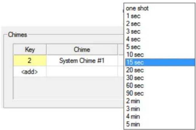
FIGURE 58. Key Options Page – Chimes Group Box
To configure a chime notification, do the following:
1. Click the Key browse button

The Key Selection window opens.
| Row | Page | 1 | 2 | 3 | 4 | 5 | 6 | 7 | 8 | 9 | 10 | 11 | 12 | 13 | 14 |
| 1 | 1 | ||||||||||||||
| 2 | |||||||||||||||
| 3 | |||||||||||||||
| 4 | |||||||||||||||
| 5 | |||||||||||||||
| 6 | |||||||||||||||
| 7 | |||||||||||||||
| 8 |
-
Select the key you want to assign the chime notification.
-
Click OK.
The Key Selection window closes and the key number appears in the field.
- From the Chime column drop down menu, select the chime you want to assign.
- From the Duration column drop down menu, select the duration the chime notification should last.
Key Icons Group Box
The Key Icons group box is used to determine which key states will display an icon to visually represent their assigned state.
For more information, see "Key Options Menu, Icons" on page 226.

FIGURE 59. Key Options Page – Key Icons Group Box
To enable key icons, do the following:
In the Display column, select the check box next to the key state you want to display an icon.
Key Volumes Group Box

FIGURE 60. Key Options Page – Key Volumes Group Box
Allow Key Volume Adjustments Check Box
The Allow Key Volume Adjustments check box is used to globally enable or disable key volume adjustments.
To enable key volume adjustments, do the following:
Select the Allow Key Volume Adjustments check box.
Minimum Key Volumes Table
The Minimum Key Volumes table is used to adjust minimum volumes for each key on the keypanel.
To adjust minimum volumes, do the following:
1. In the Key column field, click the browse button . The Key Selection window appears.
| Row | Page | 1 | 2 | 3 | 4 | 5 | 6 | 7 | 8 | 9 | 10 | 11 | 12 | 13 | 14 |
| 1 | 1 | ||||||||||||||
| 2 | |||||||||||||||
| 3 | |||||||||||||||
| 4 | |||||||||||||||
| 5 | |||||||||||||||
| 6 | |||||||||||||||
| 7 | |||||||||||||||
| 8 |
-
Select the key you want to adjust.
-
Click OK.
The Key Selection window closes.
- Using the Volume column spin box, adjust the minimum volume of the key.
Audio Options Page
IMPORTANT: OMNEO 3 through OMNEO 8 only appear when the Audio Package is purchased, otherwise, they do not display.

FIGURE 61. Keypanel Configuration – Audio Options
Mic Modes Group Box
The Mic Modes group box is used to configure panel mics and headset mics.
Available options for this group box are:
Disabled
Enabled
Switched
When set to Switched Mode, the state of the Panel Mic is controlled by the Mic Sel key.
The default for the Rear Panel Mic is disabled, while the default for the Front Panel Mic is switched.
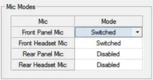
FIGURE 62. Audio Options Page – Mic Modes Group Box
To configure the mic mode, do the following:
From the Mode column drop down list, select the mode for the microphone you want to configure.
Speaker / Headset Modes Group Box
The Speaker / Headset Modes group box is used to configure the way the speakers or headsets act.
For more information, see, "Audio Options Menu, Speaker" on page 210 or "Audio Options Menu, Headset Mic" on page 201.
| Output | Mode |
| Front Speaker | Switched |
| Rear Speaker | Disabled |
| Left Headset (Left) | Always On |
| Left Headset (Right) | Always On |
| Right Headset (Left) | Always On |
| Right Headset (Right) | Always On |
FIGURE 63. Audio Options Page – Speaker / Headset Modes Group Box
To configure speaker/headset modes, do the following:
From the Mode column drop down menu, select the mode for the output desired.
Aux Inputs Group Box
The Aux Inputs group box is used to enable or disable the volume control for audio inputs through the front panel encoder. For more information, see “Audio Options Menu, Inputs” on page 204.
IMPORTANT: OMNEO 3 through OMNEO 8 only appear when the Audio Package is purchased, otherwise, they do not display.

FIGURE 64. Audio Options Page – Aux Inputs Group Box
Input Display Column
The Input Display column displays the available inputs that can be enabled or disabled.
Mode Drop Down Menu Column
The Mode drop down column is used to enable and disable he Aux Inputs.
NOTE: OMNEO 4, 6, 8 have the ganged option. You can gang OMNEO 3+4, 5+6, and 7+8
To enable or disable volume control for an input, do the following:
From the Mode column drop down menu, select Enabled or Disabled next to the desired input.
Number of Analog Aux Inputs Drop Down Menu
The Number of Analog Aux Inputs drop down menu is used to select the number of auxiliary inputs on the keypanel when the panel has been licensed for OMNEO 3-8.
When the keypanel is licensed for OMNEO 3–8, OMNEO 8 and Aux 1 are multiplexed, meaning you can have one or the other, but not both. The same rule applies to OMNEO 7 and Aux 2; both are muxed and both cannot be used together. Also, you cannot have Aux 2 without Aux 1.
The options available for the OMNEO 3–8:
• Number of Analog Aux = 2, OMNEO 1-6, plus Aux 1-2
• Number of Analog Aux = 1, OMNEO 1-7, plus Aux 1
• Number of Analog Aux = 0, OMNEO 1-8
When a keypanel is not licensed with the Audio package, meaning it only has OMNEO 1 and 2, then the number of analog aux inputs is the maximum supported by the panel:
- KP-5032/4016 and KP-5032PB/4016PB - Maximum number of Analog Aux = 2, OMNEO 1-2, plus Aux 1-2
- DKP-4016 - Maximum number of Analog Aux = 1, OMNEO 1-2, plus Aux 1
- KP-3016- Maximum number of Analog Aux = 0, OMNEO 1-2
• KP-3016A does not support OMNEO
When changes are made, such as the number of analog aux inputs is changed from 0 to 2, the changes are available but are not displayed until you have exited and reloaded the window.
Mic Options Group Box
The Mic Options group box is used to choose how audio is routed to the Preamp Output connector, configure the actions of the Mic Mute key, to enable or disable mic gain on the keypanel, and to configure AEC ^1 (Acoustic Echo Cancellation) prioritization on a microphone.
- For further explanation of the available selections for the Mic Preamp Mode drop down menu, see "Audio Options Menu, Preamp Out" on page 209.
- For further explanation of the available selections for the Mic Mute Mode drop down menu, see “Audio Options Menu, Mic Mute” on page 208.
- For further explanation of the available selections for the Mic Gain Adjust Source drop down menu, see "Audio Options Menu, Mic Gain" on page 207.
- For further explanation of the available selection for the AEC Mic Priority drop down menu, see "AEC" on page 187.

FIGURE 65. Audio Options Page – Mic Options Group Box
To configure mic options, do the following:
- From the Mic Precamp Mode drop down menu, select Switched, Hot, Disabled, or Inverted.
- From the Mic Mute Mode drop down menu, select Disabled, Toggle, or Momentary.
- From the Mic Gain Adjust Source drop down menu, select the mic gain adjust source.
- From the AEC Mic Priority drop down menu, select front or rear.
Matrix Out and Sidetone Options Group Box
The Matrix Out and Sidetone Options group box is used to select whether audio from the selected active mic goes out to the Matrix when a talk key is active (NORMAL mode) or audio goes out the Matrix without regard to the talk key state (HOT MIC mode) and at what output level to send it.
Also, from this group box, configure the mode and level at which the user hears their own voice. For more information, see, "Audio Options Menu, Sidetone" on page 210.

FIGURE 66. Audio Options Page – Matrix Out and Sidetone Options Group Box
To configure the matrix output mode and level, do the following:
- From the Matrix Output Mode, select Switched or Hot Mic.
- Using the Matrix Output Level scroll box, adjust the output level as desired.
To configure the sidetone mode and level, do the following:
- From the Sidetone Mode, select Switched, Always On, or Disabled.
- Using the Sidetone Level scroll box, adjust the Sidetone level as desired.
Headset Configuration Group Box
The Headset Configuration group box is used to define the microphone type – Auto-detect, Dynamic, or Electret. Also from this group box, you configure Auto-Transfer and Auto-Mute.
For more information, see "Type" on page 202, "Auto-Transfer" on page 203, "Auto-Mute" on page 201
Headset Configuration
| Headset | Mic Type | Mic Auto-Mute | Headset Auto-Transfer |
| Left Headset | Auto Detect | ☒ | ☒ |
| Right Headset | Auto Detect | ☒ | ☒ |

Headset Transfer Active
FIGURE 67. Audio Options Page – Headset Configuration Group Box
To configure a headset, do the following:
- From the Mic Type column drop down menu, select Auto Detect, Dynamic, or Electret.
- Select the Mic Auto-Mute check box to automatically mute mic input when a headset mic is not detected.
- Select the Headset Auto-Transfer check box to allow the keypanel to automatically enter or leave headset mode when a headset is installed or removed.
- Select the Headset Transfer Active check box to make the headset active.
Ganged Volume Group Box
The Ganged Volume group box is used to set what happens when adjusting the volume for a ganged channel pair when the volumes are not identical and one of the volumes reaches the minimum or maximum level.
For more information on the available selections, see "Audio Options Menu, Ganged Vols" on page 201.
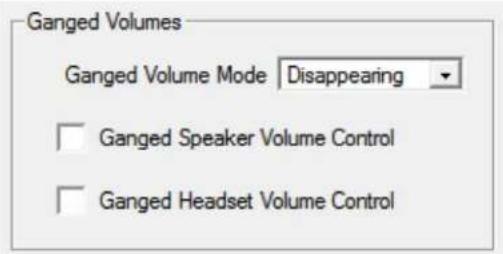
FIGURE 68. Audio Options Page – Ganged Volumes Group Box
To configure ganged volumes, do the following:
- From the Ganged Volume Mode drop down menu, select Disappearing or Fixed.
- Select the Ganged Speaker Volume Control check box to enable the speaker volumes to be ganged.
- Select the Ganged Headset Volume Control check box to enable the headset volumes to be ganged.
Tone Generator Group Box
The Tone Generator group box is used to define the tone frequency. The tone generator is used to check the audio path from the keypanel to the matrix.
Available selections for this menu are:
500Hz Tone (default)
1kHz Tone

FIGURE 69. Audio Options Page – Tone Generator Group Box
To configure the tone generator, do the following:
From the Tone Frequency drop down menu, select 500 Hz or 1000 Hz.
VM Options Group Box
The VM Options group box is used to configure voice messaging playback options and recording options.
For more information, see "Audio Options Menu, VM Options (Audio Package Only)" on page 212.

FIGURE 70. Audio Options Page – VM Options Group Box
To configure voice messaging options, do the following:
- Select the Isolate During Playback check box to remove all other audio from the speaker or headset when playing back voice messages.
- From the When Mailbox Full drop down menu, select Reject New or Delete Oldest.
- From the Auto-Record drop down menu, select Disabled or Rolling Buffer.
Audio Levels Page
IMPORTANT: OMNEO 3 through OMNEO 8 only appear when the Audio Package is purchased, otherwise, they do not display.
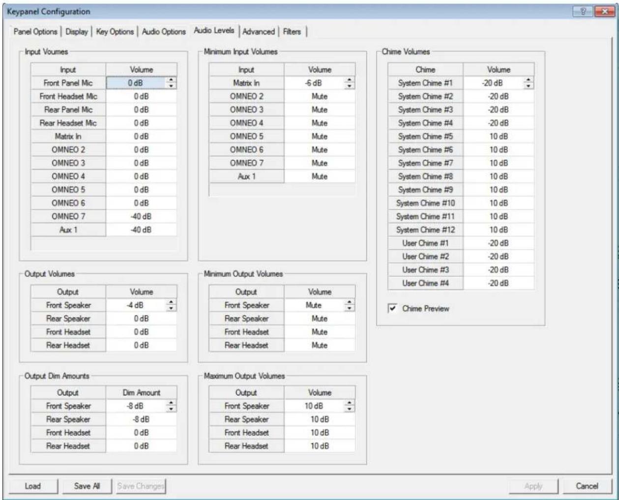
FIGURE 71. Keypanel Configuration – Audio Levels
Input Volumes Group Box
The Input Volumes group box is used to adjust the current volume, in dB, for all input sources.
IMPORTANT: OMNEO 3 through OMNEO 8 only appear when the Audio Package is purchased, otherwise, they do not display.
The range for this field is -48dB to 10dB, and Mute.
The default setting is 0dB.
| Input | Volume |
| Front Panel Mic | 0 dB |
| Front Headset Mic | 0 dB |
| Rear Panel Mic | 0 dB |
| Rear Headset Mic | 0 dB |
| Matrix In | 0 dB |
| OMNEO 2 | 0 dB |
| OMNEO 3 | 0 dB |
| OMNEO 4 | 0 dB |
| OMNEO 5 | 0 dB |
| OMNEO 6 | 0 dB |
| OMNEO 7 | -40 dB |
| Aux 1 | -40 dB |
FIGURE 72. Audio Levels Page – Input Volumes Group Box
To configure input volumes, do the following:
Using the Volume column spin box, adjust the volume for the input desired.
Output Volumes Group Box
The Output Volumes group box is used to set the volume level, in dB, for outputs at the keypanel. This is the volume level available when using the Main Volume control knob, located on the front of the keypanel
| Output | Volume |
| Front Speaker | -4 dB |
| Rear Speaker | 0 dB |
| Front Headset | 0 dB |
| Rear Headset | 0 dB |
FIGURE 73. Audio Levels Page – Output Volumes Group Box
To configure output volumes, do the following:
Using the Volume column spin box, adjust the volume for the output desired.
Minimum Output Volumes Group Box
The Minimum Output Volume group box is used to set the minimum volume level, in dB, for different outputs on the keypanel. This is the minimum volume level available when using the Main Volume control knob, located on the front of the keypanel.
The range for this field is Mute, -48dB to +10dB. The default setting is Mute.

FIGURE 74. Audio Levels Page – Minimum Output Volumes Group Box
To configure the minimum output volumes, do the following:
Using the Volume column spin box, adjust the minimum volume for the output desired.
Output Dim Amounts Group Box
The Output Dim Amounts group box is used to set how much the output is dimmed when a talk key is pressed.
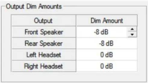
FIGURE 75. Audio Levels Page – Output Dim Amounts Group Box
To configure output dim amounts, do the following:
Using the Volume column spin box, adjust the output dim for the output desired.
Minimum Input Volumes Group Box
The Minimum Input Volume group box is used to set the minimum volume level, in dB, for different sources on the keypanel. This is the minimum volume level available when using the Aux Volume control knob, located on the front of the keypanel.
IMPORTANT: OMNEO 3 through OMNEO 8 only appear when the Audio Package is purchased, otherwise, they do not display.
The range for this field is -48dB to 10dB, and Mute.
By default, this field for Matrix In is set to -6dB; all other inputs are set to Mute.
| Input | Volume |
| Matrix In | -6 dB |
| OMNEO 2 | Mute |
| OMNEO 3 | Mute |
| OMNEO 4 | Mute |
| OMNEO 5 | Mute |
| OMNEO 6 | Mute |
| OMNEO 7 | Mute |
| OMNEO 8 | Mute |
FIGURE 76. Audio Levels Page – Minimum Input Volumes
To configure input volumes, do the following:
Using the Volume column spin box, adjust the volume for the input desired.
Maximum Output Volumes Group Box
The Maximum Output Volumes group box is used to set the maximum level, in dB, of the volume the user can configure for a headset or a speaker. This feature prevents incoming audio from being too loud.
The range for this field is -48dB to 10dB, and Mute. The default setting is 10dB.

FIGURE 77. Audio Levels Page – Maximum Output Volumes Group Box
To configure maximum output volumes, do the following:
Using the Volume column spin box, adjust the maximum volume for the output desired.
Chime Volumes Group Box
The Chime Volumes group box is used to set the volume for each of the built-in chimes, as well as to enable or disable preview of chimes during chime selection in this menu and others that reference chimes.
For a description of the range of volumes available, see "Audio Options Menu, Chime" on page 200.
| Chime | Volume |
| System Chime #1 | -20 dB |
| System Chime #2 | -20 dB |
| System Chime #3 | -20 dB |
| System Chime #4 | -20 dB |
| System Chime #5 | -20 dB |
| System Chime #6 | -20 dB |
| System Chime #7 | -20 dB |
| System Chime #8 | -20 dB |
| System Chime #9 | -20 dB |
| System Chime #10 | -20 dB |
| System Chime #11 | -20 dB |
| System Chime #12 | -20 dB |
| User Chime #1 | -20 dB |
| User Chime #2 | -20 dB |
| User Chime #3 | -20 dB |
| User Chime #4 | -20 dB |
FIGURE 78. Audio Levels Page – Chime Volumes Group Box
IMPORTANT: User Chimes are only present when the Audio Package is installed.
To configure chime volumes, do the following:
- From the Volume column spin box, adjust the volume for the System or User Chime desired.
- Select the Chime Preview check box to hear a preview of the chime on the keypanel each time a new chime is selected or while the volume is being adjusted.
Advanced Page
IMPORTANT: OMNEO 3 through OMNEO 8 only appear when the Audio Package is purchased; otherwise, they do not display.

FIGURE 79. Keypanel Configuration - Advanced
AGC Group Box
The AGC (Automatic Gain Control) group box is used to set the speed at which a microphone becomes active and the speed at which a sustainable level is achieved through the use of the Attack menu and the Decay menu. You can set these levels for the front, rear, and headset microphones used with the keypanel. For information on available selections, see "AGC" on page 188.
| Mic | Attack Time | Decay Time |
| Front Panel Mic | 1 msec | 500 msec |
| Rear Panel Mic | 1 msec | 500 msec |
| Left Headset Mic | 1 msec | 500 msec |
| Right Headset Mic | 1 msec | 500 msec |
FIGURE 80. Advanced Page – AGC Group Box
To configure AGC, do the following:
- From the Attack Time column drop down menu, select the speed to configure for Attack (microphone is active).
- From the Decay Time column drop down menu, select the speed to configure for Decay (microphone is at sustainable level).
Mixing Group Box
The Mixing group box allows you to route selected input audio signals to different destinations. For a complete list of destinations and more information, see “Mixing” on page 197.
IMPORTANT: OMNEO 3 through OMNEO 8 only appear when the Audio Package is purchased, otherwise, they do not display.
| Mixing | ||||||||||||
| Front Panel Mic | Rear Panel Mic | Matrix In | OMNEO 2 | OMNEO 3 | OMNEO 4 | OMNEO 5 | OMNEO 6 | OMNEO 7 | OMNEO 8 | Left Headset Mic | Right Headset Mic | |
| Front Speaker | ☒ | ☒ | ☒ | ☒ | ☒ | ☒ | ☒ | |||||
| Rear Speaker | ||||||||||||
| To Matrix | ||||||||||||
| Preamp Out | ||||||||||||
| OMNEO 2 | ||||||||||||
| Left Headset (Left) | ||||||||||||
| Left Headset (Right) | ||||||||||||
| Right Headset (Left) | ||||||||||||
| Right Headset (Right) | ||||||||||||
FIGURE 81. Advanced Page - Mixing Group Box
To mix inputs and outputs, do the following:
- Using both axis lists, select the check boxes that correlate to the inputs and outputs you want to mix.
- From the Mix Mode drop down menu, select Switched or Always On.
For more information on Mix Mode, see "Mix Mode" on page 199.
IMPORTANT:
Not every input can be mixed to every output. Check boxes are not present for mixes that cannot be set here. Some mixes are made using the Headset/Speaker and Headset Mic/Panel Mic menus when setting the modes to Always On/Enabled, Disabled, or Switched.
Compression Group Box
The Compression group box is used to change the audio's gain, meaning audio above the noise gate threshold is changed according to the compression ratio selected. The compression is used to change the dynamic range of the mic input. This means loud sounds are softened; while soft sounds are amplified.
IMPORTANT: Compression ratios 4:1, 5:1, and 6:1 are only available with the purchase of the Audio Package. For more information, see “Audio and Control Packages” on page 303.
For more information on compression values available, see "Compression" on page 189.
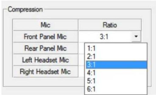
FIGURE 82. Advanced Page – Compression Group Box
To configure compression on a microphone, do the following:
From the Ratio column drop down menu, select the compression ratio desired.
Gating Group Box
The Gating group box is used to minimize or eliminate background noise problems by shutting off an audio source when the audio level drops below a certain threshold.
IMPORTANT: OMNEO 3 through OMNEO 8 only appear when the Audio Package is purchased, otherwise, they do not display.
The range for the gating threshold is -17dB to +18dB, and Disabled. By default, the gating threshold is set to Disabled.
| Input | Threshold |
| Front Panel Mic | Disabled |
| Rear Panel Mic | Disabled |
| Matrix In | Disabled |
| OMNEO 2 | Disabled |
| OMNEO 3 | Disabled |
| OMNEO 4 | Disabled |
| OMNEO 5 | Disabled |
| OMNEO 6 | Disabled |
| OMNEO 7 | Disabled |
| OMNEO 8 | Disabled |
| Left Headset Mic | Disabled |
| Right Headset Mic | Disabled |
FIGURE 83. Advanced Page – Gating Group Box
To configure gating on an input, do the following:
Using the Threshold column enable and set the threshold you desire for the input of your choice.
Noise Gate Group Box
The Noise Gate group box is used to enable, disable or adjust (if licensed) the audio level at which the mic turns on.
If not licensed, noise gate can be enabled or disabled. When enabled, microphone noise gate is set to -72dBu; when the noise gate is disabled, the microphone is always on.
If licensed for the Audio Package, you have the ability to adjust the threshold level of the noise gate, giving you more flexibility configuring the noise gate.
For more information, see "Noise Gate" on page 199.

FIGURE 84. Advanced Page – Noise Gate Group Box
To enable and adjust the noise gate, do the following:
Using the scroll box in the Threshold column, enable and set the threshold for the input desired.
Filters Page
The Filters page is used to add input and output bandpass filters, frequency response (equalization) filters or notch filters to a Matrix In source.
IMPORTANT: OMNEO 3 through OMNEO 8 only appear when the Audio Package is purchased, otherwise, they do not display.

FIGURE 85. Keypanel Configuration – Filters Page
Input Bandpass Filters Group Box
The Input Bandpass Filters group box is used to enable bandpass filters which set a low and high frequency range where frequencies within the two frequency points are passed and anything outside of the range is rejected.
IMPORTANT: OMNEO 3 through OMNEO 8 only appear when the Audio Package is purchased, otherwise, they do not display.

FIGURE 86. Filters Page – Input Bandpass Filters Group Box
To configure input bandpass filters, do the following:
- Select the Enabled column check box for the input you want to set a bandpass filter.
- From the Low Freq column drop down menu, select the low frequency you desire.
- From the High Freq column drop down menu, select the high frequency you desire.
Output Bandpass Filters Group Box
The Output Bandpass Filters group box is used to enable bandpass filters which set a low and high frequency range where frequencies within the two frequency points are passed and anything outside of the range is rejected.

FIGURE 87. Filters Page – Output Bandpass Filters Group Box
To configure output bandpass filters, do the following:
- Select the Enabled column check box for the input you want to set a bandpass filter.
- From the Low Freq column drop down menu, select the low frequency you desire.
- From the High Freq column drop down menu, select the high frequency you desire.
Input Equalization Filters Group Box
Equalization allows the user to select predefined settings that modify the frequency envelope of an audio channel. This is a 5-band equalizer. Each preset provides a different EQ to be applied to the audio.
For more information on available options, see "Equalization" on page 191.
IMPORTANT:
Included in the purchased audio package, is an adjustable 5-band equalizer giving you the ability adjust the low and high frequency cutoff filters and the gain for each band. This feature is in addition to the preset frequencies that comes standard on the keypanel. If the audio package is not purchased the high, low frequency and band gains all display as read only.

FIGURE 88. Filters Page – Input Equalization Filters Group Box
To configure the input equalization filters, do the following:
- Select the Enabled column check box next to the input you want to filter.
- From the Preset column drop down menu, select the preset you want to use, if desired.
IMPORTANT: You can only change the frequencies and gains if licensed.
- From the Low Freq column drop down menu, select the low frequency you desire.
-
From the High Freq column drop down menu, select the high frequency you desire.
-
Click the Gain column browse button. The Band Gain window appears.

-
Using the Gain scroll box, adjust the gain for the appropriate band.
-
Click OK.
Output Equalization Filters Group Box
Equalization allows the user to select predefined settings that modify the frequency envelope of an audio channel. This is a 5-band equalizer. Each preset provides a different EQ to be applied to the audio.
For more information on available options, see "Equalization" on page 191.
IMPORTANT:
Included in the purchased audio package, is an adjustable 5-band equalizer giving you the ability adjust the low and high frequency cutoff filters and the gain for each band. This feature is in addition to the preset frequencies that comes standard on the keypanel.

FIGURE 89. Filters Page – Output Equalization Filters Group Box
To configure the output equalization filters, do the following:
- Select the Enabled column check box next to the output you want to filter.
- From the Preset column drop down menu, select the preset you want to use, if desired.
IMPORTANT: You can only change the frequencies and gains if licensed.
- From the Low Freq column drop down menu, select the low frequency you desire.
-
From the High Freq column drop down menu, select the high frequency you desire.
-
Click the Gain column browse button .

The Band Gain window appears.
- Using the Gain scroll box, adjust the gain for the appropriate band.
- Click OK.
Notch Filter Mode
The Notch menu allows you to add a notch filter to the Matrix In source. This can be useful when the keypanel data port signal is being heard in the audio line due to cable routing problems.
For descriptions of the available selections, see "Notch" on page 194.
By default, the notch filter is set to Disabled.
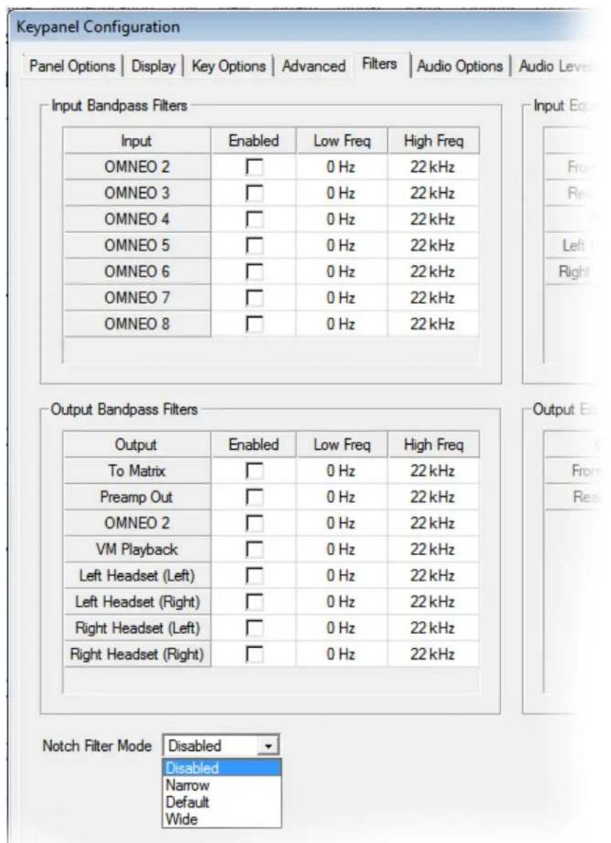
FIGURE 90. Filters Page – Notch Filter Mode Selection
To set the notch filter, do the following:
From the Notch Filter Mode drop down menu, select Disabled, Narrow, Default, or Wide.
NOTE: The instructions provided below are shown using the KP-5032, but are applicable for all family keypanels.
Download Firmware to the Keypanel From AZedit
To download firmware to the keypanel, do the following:
- Open AZedit.
- From the Status menu, select Port. The Port Status window appears.
- Find the port number where the KP-5032/4016 is assigned.
![AZedit - [ONLINE] - Keypanel Version Information File Online Authentication Edit View System Alphas Status Options KPs PLs IFBs IFB SLs SLs RYs ISOs GPIs UPL URs AGRP 001 N001 n/a 002 N Info 003 N Download firmware... 004 N Download font... 005 N 006 N 007 N007 n/a 008 N008 n/a 009 N009 n/a 010 N010 n/a 011 N011 n/a](/content/2026/05/1012724/images/90ca4eae502194bb57efe19704a1de3fbf2b0fe253001ad5c42125bc37976eb8.jpg)
- Highlight the Port (keypanel) to be updated. You may select more than one at a time by holding CTRL key down while you select.
- Right-click the highlighted selections. A popup menu appears.
-
Select Download firmware... The Firmware Download window appears.
-
Using the browse button, browse to the file to be downloaded.
- Click Open.
The Download Device Firmware window appears.
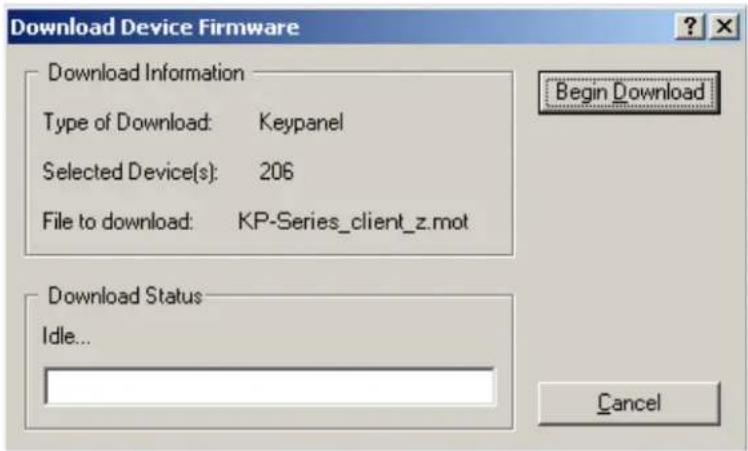
- Click Begin Download.
The download begins.

- Verify the keypanel displays the FIRMWARE DOWNLOAD message with a progression bar.
Once the download is complete, the keypanel has to process the downloaded file.

- Click OK.
The KP-5032/4016 firmware download finishes.
- Verify the keypanel displays the PROCESSING DOWNLOAD message with a progression bar.

NOTE: Processing Download is only shown if the downloaded firmware image is compressed.
- Once the keypanel is finished processing the download, the keypanel begins to reprogram.
The keypanel flashes a REPROGRAMMING DO NOT POWER OFF message in the display panel.

REPROGRAMMING DO NOT POWER OFF
NOTE:
- This can take up to 2 minutes to complete if connected via OMNEO and up to 15 minutes to complete if connected via AIO. Use the Keypanel Version Information window to follow the progress of the download. Also, the keypanel displays Firmware Download on the panel display until the download is complete.
- The KP-5032/4016 resets itself once the firmware download is complete and the flash reprogrammed.
-
While the firmware is downloading, chunk progress is displayed by incremental blocks. Also, the keypanel displays an icon warning not to turn off the panel while the flash is being reprogrammed.
-
In the Keypanel Version Information window, verify the version upgrade.
NOTE: To get to the Keypanel Version Information window, select Status|Software Versions|Kepanels.
| Port / | Alpha | Version |
| 124 | 124 | n/a |
| 125 | 125 | n/a |
| 126 | 126 | n/a |
| 127 | 127 | n/a |
| 128 | 128 | KP-5032 VERSION 1.2.0, FEB 3 2016, CRC=D9EF |
| 129 | 129 | KP-32. VERSION 2.0.7 (APR 04 2006) U2=0ABE U: |
| 130 | 130 | n/a |
| 131 | 131 | n/a |
| 132 | 132 | n/a |
| 133 | 133 | n/a |
Download Firmware to the Keypanel Using the Firmware Upload Tool
Required Firmware version:
FWUT V2.4.0 or later
To download firmware to the keypanel, do the following:
- Open the Firmware Upload Tool.
2. From the File menu, select Options.
The Firmware Upload Tool Options window appears.

3. Click the Change button.
The folder network window appears.
- Navigate to the folder where the firmware resides.
- Click OK.
- Click OK, again.
The Firmware Upload Tool Options window closes.
- From the OKP Device page, select the device you want to update.

8. Click the Upload button.
The Select Firmware for Upload window appears.
- From the list of firmware, select the firmware you want to download.

- Click the Start button.
- Once the firmware has been updated, the keypanel reboots automatically.
Enable Downloading New Bootloader from the Keypanel
IMPORTANT: If the keypanel is running firmware v2.1.0 (or v1.3.0 for OCP) downloading the bootloader is always enabled
By default, the keypanel does not allow downloading different bootloader versions – this can be enabled in the keypanel menu.
To enable the bootloader firmware downloads on the keypanel, do the following:
- While pressing the Main Vol and Aux Vol encoders on the front of the keypanel at the same time, press the MENU button. The main menu appears in the panel display.
- Using the left and right arrow buttons, select Service.
- Press the SEL button. The Service menu options appear in the panel display.
- Using the left and right arrow buttons, select Boot Code.
- Press the SEL button. Allow Download and Version X.X.X (where X represents version numbers) appears in the panel display.
- Using the left and right arrow buttons, select Allow Download.
- Press the SEL button. The keypanel now allows download of new bootloader firmware.
NOTE: If the keypanel is powered off or loses power, the state of the Allow Download option resets to not enabled. You must reconfigure the option for it to allow new bootloader firmware to be downloaded.
Download Firmware Using the Bootloader
The Bootloader is used to upload a new bootloader image or to upgrade the keypanel firmware if it is corrupt or fails and makes downloading of new firmware impossible.
If the keypanel firmware is corrupt, the panel may boot automatically into the bootloader. However, if the keypanel firmware appears valid, but fails to run properly, you may need to force the keypanel into the bootloader in order to download the new firmware.
NOTE: The instructions provided below are shown using the KP-5032 family keypanels.
Run the Bootloader
To run the bootloader, do the following:
- Power off the keypanel.
-
Verify the KP-5032/4016 is powered off, but still connected to the FRAME.
-
At the same time, press and hold keypanel key 15 in the listen position (up) and keypanel key 16 in the talk position (down), while you connect the power cord to the keypanel.
KP-5032/4016 - Boot Loader Waiting for download... appears in the panel display.

- In AZedit, from the Status menu, select Software Versions. The Software Versions popup menu appears.
- From the Software Versions popup menu, select Keypanels. The Keypanel Version Information window appears.
| Port / | Alpha | Version |
| 124 | 124 | n/a |
| 125 | 125 | n/a |
| 126 | 126 | n/a |
| 127 | 127 | n/a |
| 128 | 128 | KP-5032 BOOT LOADER, VERSION 1.2.0, FEB 3 2016, CRC=D9EF |
| 129 | 129 | KP-32, VERSION 2.0.7 (APR 04 2006) U2=0ABE U3=F4C1 |
| 130 | 130 | n/a |
| 131 | 131 | n/a |
| 132 | 132 | n/a |
| 133 | 133 | n/a |
| 134 | 134 | n/a |
| 135 | 135 | n/a |
- From the Keypanel Version Information window, find the port number where the keypanel is assigned.
NOTE: Notice the Version column is showing KP-5032/4016 Bootloader Version 1.2.0 is shown.
- Right-click on the KP-5032/4016. A popup menu appears.
- From the popup menu, select Download Firmware... The Firmware Download navigation window appears.
- Navigate to and select your firmware file (i.e., KP-Series_client_z.mot).
10. Click Open.
The Download Device Firmware window appears.

11. Click Begin Download.
The Download begins and a popup message appears.
12. Click OK.
The KP-5032/4016 firmware download finishes.
NOTE: This can take up to 15 minutes to complete if connected via AIO. Use the Keypanel Version Information window to follow the progress of the download (the number and percentage of chunks completed). Also, the firmware progression is displayed on the keypanel display until the download is complete.
NOTE: Once the Boot Loader is finished downloading, it reboots itself and reprograms the flash.

Display the FPGA Version on the Keypanel
To display the FPGA version currently installed in the keypanel, do the following:
- While pressing the Main Vol and Aux Vol encoders on the front of the keypanel at the same time, press the MENU button.
The main menu appears in the panel display.
-
Using the left and right arrow buttons, select Service.
-
Press the SEL button.
The Service menu options appear in the panel display.
-
Using the left and right arrow buttons, select FPGA Version.
-
Press the SEL button.
Version X.X.X (where X represents the FPGA version numbers) appears in the panel display.
Download and Upgrade the FPGA to the KP-5032/4016
There are four (4) phases to upgrading the FPGA on a keypanel:
• Downloading the FPGA firmware to the matrix
• Downloading the FPGA firmware to the keypanel
- Processing the download
• Reprogramming the keypanel
To download the FPGA to the keypanel, do the following:
- Open AZedit.
- From the Status menu, select Software Versions|Keypanels. The Keypanel Version Information window appears.
- Find the port number where the KP-5032/4016 is assigned.
- Highlight the Port (keypanel) to be updated. You may select more than one at a time by holding CTRL key down while you select.
- Right-click the highlighted selections. A popup menu appears.
- Select Download Firmware. The Firmware Download window appears.
- Using the browse button, navigate to the FPGA file you want to use.
8. Click Open.
The Download Device Firmware window appears.

9. Click Begin Download.
The download begins. A progress bar appears to show the progress of the download.

10. Click OK.
The KP-5032/4016 firmware download to the Matrix finishes. The Download FPGA Firmware To The Keypanel begins.
- Verify the Keypanel Version Information window is displaying the numbers of chunks (of data) transferred to the keypanel.
| Port / | Alpha | Version |
| 112 | N112 | n/a |
| 113 | N113 | n/a |
| 114 | N114 | n/a |
| 115 | N115 | n/a |
| 116 | N116 | n/a |
| 117 | N117 | n/a |
| 118 | N118 | n/a |
| 119 | N119 | n/a |
| 120 | N120 | n/a |
| 121 | N121 | n/a |
| 122 | N122 | n/a |
| 123 | N123 | n/a |
| 124 | N124 | n/a |
| 125 | N125 | n/a |
| 126 | N126 | n/a |
| 127 | N127 | n/a |
| 128 | N128 | n/a |
| 129 | N129 | n/a |
| 130 | N130 | n/a |
| 131 | N131 | Download: Chunk 15 of 72, try 1, 34% |
| 132 | N132 | n/a |
| 133 | N133 | n/a |
| 134 | N134 | n/a |
| 135 | N135 | n/a |
- Verify the keypanel displays the FPGA DOWNLOAD message with a progression bar. Once the download is complete, the keypanel has to process the downloaded file.

- Verify the Keypanel Version Information window displays Processing download on the keypanel port you chose.
![AZedit - [ONLINE] - Keypanel Version Information File Online Authentication Edit View System Alphas Status Option Port / Alpha Version 118 N118 n/a 119 N119 n/a 120 N120 n/a 121 N121 n/a 122 N122 n/a 123 N123 n/a 124 N124 n/a 125 N125 n/a 126 N126 n/a 127 N127 n/a 128 N128 n/a 129 N129 n/a 130 N130 n/a 131 N131 Processing download 132 N132 n/a 133 N133 n/a 134 N134 n/a](/content/2026/05/1012724/images/2c63fd2c93127fbb329154f9bec575e083dc8cc9ce458227ae7b41cfe36773ad.jpg)
- Verify the keypanel displays PROCESSING DOWNLOAD with a progression bar.

Once the keypanel is finished processing the download, the keypanel begins to reprogram. The keypanel flashes a REPROGRAMMING: DO NOT POWER OFF message in the display panel. This can take several minutes.

Once the reprogramming is complete, the keypanel reboots.
Download a Splash Screen
IMPORTANT:
The maximum bitmap size is 576 x 90. If the bitmap is smaller than the full screen dimensions, the keypanel centers the bitmap horizontally and vertically on the display and fills the background with the same color as the pixel in the top left corner of the splash screen.
-
Open AZedit.
-
From the Status menu, select Software Versions|Keypanels. The Keypanel Version Information window appears.
-
Find the port number where the KP-5032/4016 is assigned.
-
Highlight the Port (keypanel) to be updated. You may select more than one at a time by holding CTRL key down while you select.
-
Right-click the highlighted selections. A popup menu appears.
-
Select Download splash screen.... The Splash Screen Download window appears.
-
Click Open.
The Download Splash Screen File window appears.

-
In the Panel Size group box, select 1RU or 2RU.
-
Click Begin Download. The download begins. A progress bar appears to show the progress of the download. Once the download is complete the Download Splash Screen File window closes.
-
Verify the Keypanel Version Information window is displaying the numbers of chunks (of data) transferred to the keypanel.
![AZedit - [ONLINE] - Keypanel Version Information File Online Authentication Edit View System Alphas Status Options Logging Help KPs PLs IFBs IFB SLs SLs RYs ISOs GPIs UPL URs AGRPs ADs XPTs RVOL PAT New Open Merge Save Save As Partial Print Prat Port / Alpha Version 001 N001 n/a 002 N002 Download: Chunk 9 of 15try 1, 63% 003 N003 n/a 004 N004 n/a 005 N005 n/a 006 N006 n/a 007 N007 n/a 008 N008 n/a](/content/2026/05/1012724/images/6d2d7cefbb65fa95b9ad3ebf4f2f6d3609e6c6dc07841ec8a2a99dc373c9212f.jpg)
- Verify the keypanel displays the SPLASH DOWNLOAD message with a progression bar.
Once the download is complete, the keypanel has to process the downloaded file.

Once the keypanel is finished processing the download, the keypanel begins to reprogram. The keypanel flashes a REPROGRAMMING: DO NOT POWER OFF message in the display panel. This can take several minutes.

Once the reprogramming is complete, the keypanel reboots.
Download a Font File
- Open AZedit.
- From the Status menu, select Software Versions|Keypanels. The Keypanel Version Information window appears.
- Find the port number where the KP-5032/4016 is assigned.
- Highlight the Port (keypanel) to be updated. You may select more than one at a time by holding CTRL key down while you select.
- Right-click the highlighted selections. A popup menu appears.
- Select Download font.... The Font Download window appears.
- Navigate to the font file (.kpf) you want to use.
- Click Open. The Download Keypanel Font window appears.

- Click Begin Download.
The download begins. A progress bar appears to show the progress of the download.
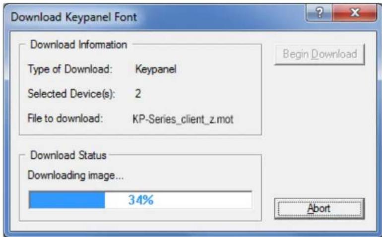
Once the download is complete the Download Keypanel Font window closes.
- Verify the Keypanel Version Information window is displaying the numbers of chunks (of data) transferred to the keypanel.
![AZedit - [ONLINE] - Keypanel Version Information File Online Authentication Edit View System Alphas Status Options Logging Help KPs PLs IFBs IFB SLs SLs RYs ISOs GPIs UPL URs AGRPs ADs XPTs RV PAT New Open Merge Save Save As Partial Print Port / Alpha Version 001 N001 n/a 002 N002 Download: Chunk 9 of 15 try 1, 63% 003 N003 n/a 004 N004 n/a 005 N005 n/a 006 N006 n/a 007 N007 n/a 008 N008 n/a 009 N009 n/a](/content/2026/05/1012724/images/e5cd7ba85e774d9b9d069bec0f23a36b02ca6323f43872d37a90a3080e45c15a.jpg)
- Verify the keypanel displays the FONT DOWNLOAD message with a progression bar.
Once the download is complete, the keypanel has to process the downloaded file.

- Verify the Keypanel Version Information window displays Processing download on the keypanel port you chose.
![AZedit - [ONLINE] - Keypanel Version Information File Online Authentication Edit View System Alphas Status Option Port / Alpha Version 118 N118 n/a 119 N119 n/a 120 N120 n/a 121 N121 n/a 122 N122 n/a 123 N123 n/a 124 N124 n/a 125 N125 n/a 126 N126 n/a 127 N127 n/a 128 N128 n/a 129 N129 n/a 130 N130 n/a 131 N131 Processing download 132 N132 n/a 133 N133 n/a 134 N134 n/a](/content/2026/05/1012724/images/e1a2d5349fb35cc6e19e44afcea3a692607dde2fac0a982fff854e4d14b842e9.jpg)
- Verify the keypanel displays the PROCESSING DOWNLOAD message with a progression bar.

Once the keypanel is finished processing the download, the keypanel begins to reprogram. The keypanel flashes a Reprogramming: Do Not Power Off message in the display panel. This can take several minutes.

Once the reprogramming is complete, the keypanel reboots.
Download an Icon File
IMPORTANT: The following instructions can be used for either panel icons or tally (key overlay) icons.
To download an icon file, do the following:
- Open AZedit.
- From the Status menu, select Software Versions|Keypanels. The Keypanel Version Information window appears.
- Find and select the Port (keypanel) to be updated. You may select more than one at a time by holding the CRTL key down while you select.
- Right-click the highlighted selection. A popup menu appears.
![AZedit - [ONLINE] - Keypanel Version Information File Online Authentication Edit View System Alphas Status Options Logging Help Port Alpha Version 001 N001 KB 5022 Version 1.03, Sep 4 2015, CRC=1a35 003 N00 002 N00 004 N00 005 5 006 6 n/a 007 7 n/a 008 8 n/a 009 9 n/a](/content/2026/05/1012724/images/b5759cb761d29b9f6cadb8a3bb35c4a9b3219129aa873bbf4dd3f848bae45537.jpg)
- Select Download icons....
The Icon Download window appears.
-
Navigate to the icon file (.bmp or .jpg) you want to use.
-
Click Open.
The Download Icon File window appears.
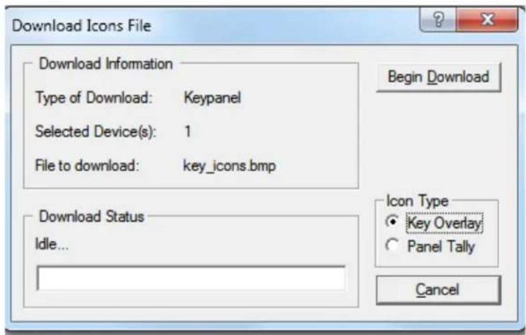
-
Verify the correct Icon Type radio button is selected – Key Overlay or Panel Tally radio button.
-
Click Begin Download.
The download begins. A progress bar appears showing the progress of the download.
Once the download is complete the Download Keypanel Font window closes.
- Verify the Keypanel Version Information window displays the numbers of chunks (of data) transferred to the keypanel.
![AZedit - [ONLINE] - Keypanel Version Information File Online Authentication Edit View System Alphas Status Options Logging Help Port Alpha Version / 001 N001 Download: Chunk 6 of 9, try 1, 41% 003 N003 Unknown 002 N002 n/a 004 N004 n/a 005 5 n/a](/content/2026/05/1012724/images/c41b95fdb8aacbde26e61901d4c1e4c81a31043c2db6f641564e66e650a62d01.jpg)
- Verify the keypanel displays the ICON DOWNLOAD message with a progression bar.

Once the keypanel is finished, it begins to reprogram. The keypanel flashes a REPROGRAMMING: DO NOT POWER OFF message in the display panel. This can take several minutes.

REPROGRAMMING DO NOT POWER OFF
Once the reprogramming is complete, the keypanel reboots.
Download User Chimes (Control Package Only)
-
Open AZedit.
-
From the Status menu, select Software Versions|Keypanels. The Keypanel Version Information window appears.
-
Find the port number where the KP-5032/4016 is assigned.
-
Highlight the Port (keypanel) to be updated. You may select more than one at a time by holding CTRL key down while you select.
-
Right-click the highlighted selections. A popup menu appears.
-
Select Download Chime.... The Font Download window appears.
-
Navigate to the chime file (.wav or .mp3) you want to use.
-
Click Open. The Download chime window appears.

- Choose a User Slot.
10. Click Begin Download.
The download begins. A progress bar appears to show the progress of the download.

Once the download is complete the Download Keypanel Font window closes.
- Verify the Keypanel Version Information window is displaying the numbers of chunks (of data) transferred to the keypanel.
![Port Alpha Version / 126 126 DKP-4016, Version 1.0.0, Mar 2 2015, CRC=4185 123 123 DKP-4016, Version 1.0.3, Sep 4 2015, CRC=1a35 134 134 DKP-4016, Version 1.0.4 [RSTP], Oct 29 2015, CRC=4594 068 68 Download: Chunk 4 of 18, try 1, 72% 124 124 DKP-4016W, Version 1.0.3, Sep 2 2015, CRC=879c 069 69 DKP-4016W, Version 1.1.0-MTP-001 [RSTP], Nov 6 2015, CRC=181b 131 131 KP-12 KEYPANEL, VER. 1A.0.26 066 66 KP-3016, Version 1.1.0-MTP-001 [RSTP], Nov 6 2015, CRC=181b 001 1 KP-4016, Version 1.0.3 (OCA-4.20RC1-1351), Nov 9 2015, CRC=d1a3 067 67 KP-5032, Version 1.1.0-MTP-001 [RSTP], Nov 6 2015, CRC=181b 080 80 KP-5032, Version 1.1.0-MTP-001 [RSTP], Nov 6 2015, CRC=181b 129 129 KP832-20, VERSION 2.0.2 (MAY 13 2005), U2=29BA, U3=6DCD 130 130 RP-1000, Version 2.0.8, Sep 2 2014, CRC=b87c 002 2 n/a 003 3 n/a Show RVON/OMNEO versions KPs PLs IFBs IFB SLs SLs RYs ISOs GPIs UPL URs AGRPs ADs XPTs RVON Vox Gains Alphas Keypanels MC I/O Cards For Help, press F1 LOCL PP 068 ALARMS:7 USERS:2 ONLINE ADAM](/content/2026/05/1012724/images/4b904926f0790ff500ed5bfeb4f0f0e0b468d8385e6ad735e117c6c259b4bcaf.jpg)
- Verify the keypanel displays the CHIME DOWNLOAD message with a progression bar.
Once the download is complete, the keypanel has to process the downloaded file.
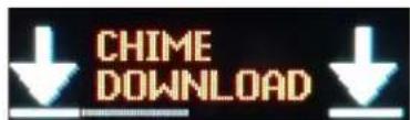
Once the keypanel has finished the download, the keypanel begins to reprogram.
The keypanel flashes a REPROGRAMMING: DO NOT POWER OFF message in the display panel. This can take several minutes.

REPROGRAMMING DO NOT POWER OFF
Once the reprogramming is complete, the keypanel reboots.
Download Screen Savers (Control Package Only)
IMPORTANT: Recommended screen saver bitmap file size:
KP-4016 - min 16x16, max 192x60 (W x H)
KP-5032 - min 16x16, max 192x130 (W x H)
To download a screen saver image, do the following:
- Open AZedit.
- From the Status menu, select Software Versions|Keypanels. The Keypanel Version Information window appears.
- Find the port number where the KP-5032/4016 is assigned.
- Highlight the Port (keypanel) to be updated. You may select more than one at a time by holding CTRL key down while you select.
- Right-click the highlighted selections. A popup menu appears.
- Select Download Screen Saver.... The Font Download window appears.
- Navigate to the screen saver file (.jpg, .bmp, .gif, .tif, .png) you want to use.
- Click Open. The Download chime window appears.
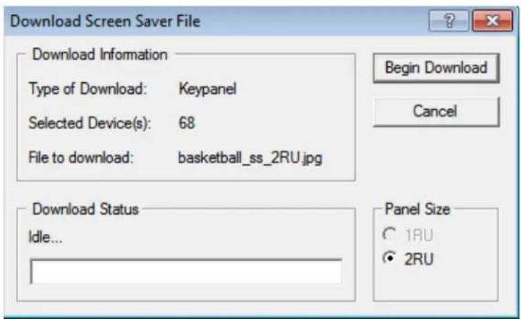
- From the Panel Size Group Box, select either the 1 RU radio button or 2 RU radio button.
IMPORTANT: If the image is too large for a 1 RU keypanel, AZedit auto-selects 2 RU.
10. Click Begin Download.
The download begins. A progress bar appears to show the progress of the download.

Once the download is complete the Download Keypanel Font window closes.
- Verify the Keypanel Version Information window is displaying the numbers of chunks (of data) transferred to the keypanel.
| Port | Alpha | Version / |
| 126 | 126 | DKP-4016, Version 1.0.0, Mar 2 2015, CRC=4185 |
| 134 | 134 | DKP-4016, Version 1.0.4 [RSTP], Oct 29 2015, CRC=4594 |
| 068 | 68 | Download: Chunk 1, try 1, 0% |
| 070 | 70 | DKP-4016, Version 1.1.0-MTP-001 [RSTP], Nov 6 2015, CRC=181b |
| 124 | 124 | DKP-4016W, Version 1.0.3, Sep 2 2015, CRC=879c |
| 069 | 69 | DKP-4016W, Version 1.1.0-MTP-001 [RSTP], Nov 6 2015, CRC=181b |
| 131 | 131 | KP-12 KEYPANEL, VER. 1A.0.26 |
| 066 | 66 | KP-3016, Version 1.1.0-MTP-001 [RSTP], Nov 6 2015, CRC=181b |
| 001 | 1 | KP-4016, Version 1.0.3 (OCA-4.20RC1-1351), Nov 9 2015, CRC=d1a |
| 136 | 136 | KP-4016, Version 1.1.0-MTP-001 [RSTP], Nov 6 2015, CRC=181b |
| 080 | 80 | KP-5032, Version 1.1.0-MTP-001 [RSTP], Nov 6 2015, CRC=181b |
- Verify the keypanel displays the SCRN SAVER DOWNLOAD message with a progression bar.

Once the keypanel is finished downloading, the keypanel begins to reprogram. The keypanel flashes a REPROGRAMMING: DO NOT POWER OFF message in the display panel. This can take several minutes, Once the reprogramming is complete, the keypanel reboots.

NOTE: A menu system quick reference chart is located at "Keypanel Menu Quick Reference" on page 269.
Main Menu Access
IMPORTANT: For more detailed information on Basic Key operation, see “Menu Navigation and Shaft Encoder Knobs” on page 47.
The Main Menu is the top-most level of the menu structure.
Available selections for this menu are:
Audio Options
Display
Key Assign
Key Options
OMNEO Offers (present when the keypanel is running OMNEO firmware or if there is an OEI-2 connected to the AIO port)
RVON Offers (present when the keypanel is running RVON firmware or if there is an RVON-IO connected to the AIO port)
Save Config
Service
To access the main menu structure, do the following:
- On the keypanel keypad, press the MENU button.
The Information menu structure displays across the middle of the panel display.

- Using the arrow buttons on the keypad, navigate through the menu options.
- Press the SEL button.
The submenu for the selection appears.
Menu System, Audio Options
Available options for this menu are:
Advanced
Chime
Dim
Ganged Vols
Headset Mic
Headset Spkr
Inputs
Key Volumes
LCP 16 CLD
Matrix Out
Max Volume
Mic Gain
Mic Mute
Min Volume
Output Lev
Panel Mic
Preamp Out
Sidetone
Speaker
Tone Gen
VM Options
Audio Options Menu, Advanced
AEC
- AGC
- Compression
- Filters
- Gating
- Metering
- Mixing
- Mix Mode
AEC
AEC (Acoustic Echo Cancellation) is used to prevent feedback from occurring between the microphone and the speaker. AEC is only available on one microphone; by default, it is enabled on the front panel mic. When the front panel mic is disabled, AEC operates on the rear microphone.
NOTE: AEC is not available for Headset Mics.
Mic Priority
The Mic Priority menu is used to select the microphone to enable AEC on when both the front and rear mics are active.
To configure mic priority on a microphone, do the following:
- Starting at the Audio Options|Advanced|AEC menu, select Mic Priority.
- Press the SEL button.
Front Mic and Rear Mic appear in the panel display.
- Using the left and right arrow buttons, select Front Mic or Rear Mic.
- Press the SEL button.
An arrow appears next to the selected option.
AGC
The AGC (Automatic Gain Control) menu is used to set the speed at which a microphone becomes active and the speed at which a sustainable level is achieved through the use of the Attack menu and the Decay menu. You can set these levels for the front, rear, and headset microphones used with the keypanel.
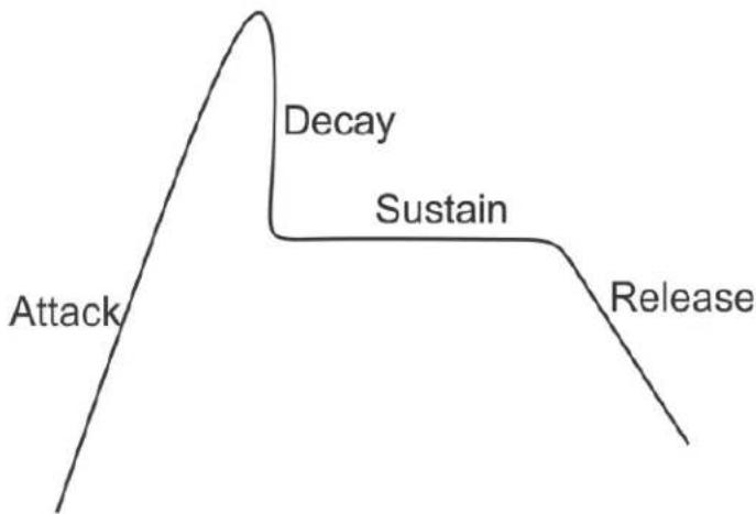
flowchart
graph TD
    A["Attack"] --> B["Decay"]
    B --> C["Sustain"]
    C --> D["Release"]
FIGURE 91. Automatic Gain Control Example
Attack
The Attack menu item is used to set the speed at which the microphone gets to the activation threshold, the point where the circuit determines if the noise is a voice. The smaller the attack time, the faster the mic turns on.
Available options for this menu are:
0.5ms
1ms (default)
2ms
Decay
The Decay menu item is used to set the speed at which the gain transitions to silence during release.
Available options for this menu are:
500ms
750ms (default)
1000ms
To configure the attack speed for a microphone source, do the following:
-
Starting at the Audio Options|Advanced|AGC menu, select Attack.
-
Press the SEL button.
Front Hdst, Front Mic, Rear Hdst, and Rear Mic appears in the panel display.
-
Using the arrow buttons, select Front Hdst, Front Mic, Rear Hdst, or Rear Mic.
-
Press the SEL button.
The Fast Attack Speed scroll box appears in the panel display.
- Using the arrow buttons, select the Attack speed you desire.
To configure the decay speed for a microphone source, do the following:
- Starting at the Audio Options|Advanced|AGC menu, select Decay.
- Press the SEL button.
Front Hdst, Front Mic, Rear Hdst, and Rear Mic appears in the panel display.
- Using the arrow buttons, select Front Hdst, Front Mic, Rear Hdst, or Rear Mic.
- Press the SEL button.
The Decay scroll box appears in the panel display.
- Using the up and down arrow buttons, select the Decay speed you desire.
Compression
The Compression menu item is used to change the audio's gain, meaning audio above the noise gate threshold is changed according to the compression ratio selected. The compression is used to change the dynamic range of the mic input. This means loud sounds are softened; while soft sounds are amplified.
Compression can be applied to the following:
- Front Headset
- Front Mic
- Rear Hdst
- Rear Mic
Available options are:
l:l
2:1
3:1(default)
Additional options with purchase of Audio Package:
4:1
5:1
6:1
To configure compression on a microphone, do the following:
- Starting at the Audio Options|Advance menu, select Compression.
-
Press the SEL button.
Front Hdst, Front Mic, Rear Hdst, and Rear Mic appear in the panel display. -
Using the arrow buttons, select the microphone source.
-
Press the SEL button.
The Compression Ratio scroll box appears in the panel display.
- Using the up and down arrow buttons, select the compression ratio you want to apply to the microphone source.
Filters
Filters allow you to add a bandpass filter, a preset frequency response (equalization) filter or a notch filter to the Matrix In audio source.
Bandpass
The Bandpass menu is used to enable using bandpass filters as well as set a low and high frequency range where frequencies within the two frequency points are passed and anything outside of the range is rejected.
To configure a bandpass range for Inputs, do the following:
- Starting at the Audio Options|Advanced|Filters menu, select Bandpass.
- Press the SEL button.
Inputs and Outputs appears in the panel display.
- Using the arrow buttons, select Input.
- Press the SEL button.
Aux 1, Aux 2, OMNEO 1, and OMNEO 2 appear in the panel display.
Or if the AUDIO package has been purchased, OMNEO 1-8 displays
- Using the arrow buttons, select either Aux 1, Aux 2, OMNEO 1 or OMNEO 2 (or OMNEO 1-8, if the audio package is purchased).
- Press the SEL button.
Frequencies and Mode appear in the panel display.
- Using the arrow buttons, select Mode.
Disabled and Enabled appear in the panel display.
- Using the arrow buttons, select Enabled.
- Press the SEL button.
An arrow appears next to the selected option.
- Press the CLR button.
Frequencies and Mode appear in the panel display. - Using the arrow buttons, select Frequencies.
- Press the SEL button.
The Low Freq scroll box and the High Freq scroll box appear in the panel display.
- Using the up and down arrow buttons, select the low frequency you desire.
- Using the left and right arrow buttons, select the high frequency scroll box.
- Using the up and down arrow buttons, select the high frequency you desire.
To configure a bandpass range for Outputs, do the following:
- Starting at the Audio Options|Advanced|Filters menu, select Bandpass.
Inputs and Outputs appears in the panel display. - Using the arrow buttons, select Output.
- Press the SEL button.
Front Hdst, Matrix Out, OMNEO 1, OMNEO 2, Preamp Out, and Rear Hdst appear in the panel display.
Or if the AUDIO package has been purchased, OMNEO 1-8 displays
- Using the arrow buttons, select the output you desire to modify.
If Front Hdst or Rear Hdst is chosen:
a. Press the SEL button.
Both, Left Chan, and Right Chan appear in the panel display.
b. Using the left and right arrow buttons, select either Both, Left Chan, or Right Chan.
- Press the SEL button.
Frequencies and Mode appear in the panel display.
- Using the arrow buttons, select Mode.
Disabled and Enabled appear in the panel display.
-
Using the arrow buttons, select Enabled.
-
Press the SEL button.
An arrow appears next to the selected option.
- Press the CLR button.
Frequencies and Mode appear in the panel display.
-
Using the left and right arrow buttons, select Frequencies.
-
Press the SEL button.
The Low Freq scroll box and the High Freq scroll box appear in the panel display.
-
Using the up and down arrow buttons, select the low frequency you desire.
-
Using the left and right arrow buttons, select the high frequency scroll box.
-
Using the up and down arrow buttons, select the high frequency you desire.
Equalization
Equalization allows the user to select predefined settings that modify the frequency envelope of an audio channel. This is a 5-band equalizer. Each preset provides a different EQ to be applied to the audio. To view all of the bands, see
Available selections for this menu are:
Default 0 dB (15Hz–20kHz)
Hiss Reduction 0 dB (15Hz–2kHz)
-6 dB (2kHz–12.6kHz)
Rumble Reduction 0 dB (50Hz–20kHz)
Noise Reduction 0 dB (50Hz–2kHz)
-6 dB (2kHz–8kHz)
-80dB (8kHz–12.6kHz)
To configure a preset frequency response for an input, do the following:
-
Starting at the Audio Options|Advanced|Filters menu, select Equalization. Inputs and Outputs appears in the panel display.
-
Using the arrow buttons, select either Input.
-
Press the SEL button.
Front Hdst, Front Mic, Matrix In, Rear Hdst and Rear Mic appear in the panel display.
-
Using the arrow buttons, select either Front Hdst, Front Mic, Matrix In, Rear Hdst or Rear Mic.
-
Press the SEL button.
Mode and Presets appear in the panel display.
- Using the arrow buttons, select Mode.
Disabled and Enabled appear in the panel display.
-
Using the arrow buttons, select Enabled.
-
Press the SEL button.
An arrow appears next to the selected option.
- Press the CLR button.
Mode and Presets appear in the panel display.
-
Using the arrow buttons, select Presets.
-
Press the SEL button.
Default, Hiss Reduction, Rumble Reduction, and Noise Reduction appear in the panel display.
-
Using the arrow buttons, select Default, Hiss Reduction, Rumble Reduction, or Noise Reduction.
-
Press the SEL button.
An arrow appears next to preset selected.
To configure a preset frequency response for an output, do the following:
- Starting at the Audio Options|Advanced|Filters menu, select Equalization. Inputs and Outputs appears in the panel display.
- Using the arrow buttons, select either Output.
- Press the SEL button. Front Spkr and Rear Spkr appear in the panel display.
- Using the arrow buttons, select either Front Spkr or Rear Spkr.
- Press the SEL button. Mode and Presets appear in the panel display.
- Using the arrow buttons, select Mode. Disabled and Enabled appear in the panel display.
- Using the arrow buttons, select Enabled.
- Press the SEL button. An arrow appears next to the selected option.
- Press the CLR button. Mode and Presets appear in the panel display.
- Using the arrow buttons, select Presets.
- Press the SEL button. Default, Hiss Reduction, and Rumble Reduction appear in the panel display.
- Using the arrow buttons, select Default, Hiss Reduction, Rumble Reduction, or Noise Reduction.
- Press the SEL button. An arrow appears next to preset selected.
Adjustable 5-Band Equalization - Audio Package Only
Included in the purchased audio package, is an adjustable 5-band equalizer giving you the ability to adjust the low and high frequency cutoff filters and the gain for each band. This feature is in addition to the preset equalization settings that comes standard on the keypanel.
| 1 2 3 4 5 | |||||||||
| low high | low high | low high | low high | high low | high | ||||
| 15.6Hz | 125Hz | 125Hz | 500Hz | 500Hz | 2000Hz | 2000Hz | 8000Hz | 12.6kHz | |
| 31.3Hz | 15.8kHz | ||||||||
| 50.0Hz | 20.0kHz | ||||||||
• Band 1 has three options for low cut-off frequency
• Bands 2, 3, and 4 have fixed frequencies
- Band 5 has three options for high cut-off frequency independent of the low frequency setting
To adjust the low and high frequency cutoff filters for Inputs, do the following:
- Starting at the Audio Options|Advanced|Filters menu, select Equalizer.
- Press the SEL button. Inputs and Outputs appears in the panel display.
- Using the arrow buttons, select Input.
- Press the SEL button. Front Hdst, Front Mic, Matrix In, Rear Hdst, and Rear Mic appear in the panel display.
- Using the arrow buttons, select the input you want to adjust.
- Press the SEL button. Frequencies, Gains, Mode and Presets appear in the panel display.
-
Using the arrow buttons, select Frequencies.
-
Press the SEL button.
The Low Freq scroll box and the High Freq scroll box appear in the panel display.
-
Using the up and down arrow buttons, select the low frequency you desire.
-
Using the left and right arrow buttons, select the high frequency scroll box.
- Using the up and down arrow buttons, select the high frequency you desire.
- Repeat steps 4 through 11 for each input.
To adjust the low and high frequency cutoff filters for Outputs, do the following:
- Starting at the Audio Options|Advanced|Filters menu, select Equalizer.
- Press the SEL button.
Inputs and Outputs appears in the panel display.
- Using the arrow buttons, select Output.
- Press the SEL button.
Front Spkr and Rear Spkr appear in the panel display.
- Using the arrow buttons, select either Front Spkr or Rear Spkr.
- Press the SEL button.
Frequencies, Gains, Mode and Presets appear in the panel display.
- Using the arrow buttons, select Frequencies.
- Press the SEL button.
The Low Freq scroll box and the High Freq scroll box appear in the panel display.
- Using the up and down arrow buttons, select the low frequency you desire.
- Using the left and right arrow buttons, select the high frequency scroll box.
- Using the up and down arrow buttons, select the high frequency you desire.
- Repeat steps 4 through 11 for each output.
To configure the 5-band gain for inputs, do the following:
- Starting at the Audio Options|Advanced|Filters menu, select Equalization.
- Press the SEL button.
Inputs and Outputs appears in the panel display.
- Using the arrow buttons, select Input
- Press the SEL button.
Front Hdst, Front Mic, Matrix In, Rear Hdst, and Rear Mic appear in the panel display.
- Using the left and right arrow buttons, select the input desired.
- Press the SEL button.
Frequencies, Gains, Mode, and Presets appear in the panel display
- Using the left or right arrow buttons, select Gains.
- Press the SEL button.
The 1: through 5: band scroll boxes appear in the panel display.
- Using the up and down arrow buttons, select the gain level you desire for Band 1.
- Using the left and right arrow buttons, select the Band 2 scroll box.
- Using the up and down arrow buttons, select the gain level you desire Band 2.
- Repeat setting the gain levels on the remaining bands.
- Repeat steps 4 through 11 for each input, desired.
To configure the 5-band gain for outputs, do the following:
-
Starting at the Audio Options|Advanced|Filters menu, select Equalization.
-
Press the SEL button.
Inputs and Outputs appears in the panel display.
-
Using the arrow buttons, select Output
-
Press the SEL button.
Front Spkr and Rear Spkr appear in the panel display.
-
Using the left and right arrow buttons, select either Front Spkr or Rear Spkr.-
-
Press the SEL button.
Frequencies, Gains, Mode, and Presets appear in the panel display
-
Using the left or right arrow buttons, select Gains.
-
Press the SEL button.
The 1: through 5: band scroll boxes appear in the panel display.
-
Using the up and down arrow buttons, select the gain level you desire for Band 1.
-
Using the left and right arrow buttons, select the Band 2 scroll box.
-
Using the up and down arrow buttons, select the gain level you desire Band 2.
-
Repeat setting the gain levels on the remaining bands.
-
Repeat steps 4 through 11 for each input, desired.
Notch
The Notch menu allows you to add a notch filter to the Matrix In source. This can be useful when the keypanel data port signal is being heard in the audio line due to cable routing problems.
By default, the notch filter is set to Disabled.
Available options for this menu are:
Disabled
Narrow 9500hz–9700Hz (200Hz band)
Default 9450hz–9750Hz (300Hz band)
Wide 9400hz–9800Hz (400Hz band)
Gating
Gating (also called VOX) allows you to minimize or eliminate background noise problems by shutting off an audio source when the audio level drops below a certain threshold.
Gating can be applied to the following:
Aux 1
Aux 2
Front Hdst
Front Mic
Matrix In
OMNEO 1
OMNEO 2 (OMNEO 1-8 appear if Audio Package is installed)
Rear Hdst
Rear Mic
The range for the gating threshold is -17dB to +18dB, and Disabled. By default, the gating threshold is set to Disabled.
Nominal inputs are as follows:
Aux 1-2 8dBu
Headset Mics -50dBu
Matrix In 8dBu
Panel Mics -42.5dBu
OMNEO 1-2 ^1
8dBu
To configure gating on the keypanel, do the following:
- Starting at the Audio Options|Advanced menu, select Gating.
- Press the SEL button.
Aux 1, Aux 2, Front Hdst, Front Mic, Matrix In, OMNEO 1, OMNEO 2, Rear Hdst, and Rear Mic appear in the panel display. (OMNEO 1-8 appears if Audio Package is installed)
- Using the left or right arrow buttons, select Aux 1, Aux 2, Front Hdst, Front Mic, Matrix In, OMNEO 1, OMNEO 2, Rear Hdst, or Rear Mic.(OMNEO 1-8 appears Audio Package is installed)
- Press the SEL button.
The Threshold scroll menu appears.
- Using the up and down arrow buttons, select the threshold you desire.
- Press BACK to go to the previous menu item OR
Press and hold CLR to exit the menu structure.
Metering
Metering allows you to monitor an audio source connected to the keypanel. The energy of the incoming audio is split into five bands and displayed on the left side of the keypanel when enabled.
The decibels display range is from 28dB below nominal to 8dB above nominal. The bands are defined as:
Band 1 100 Hz to 400 Hz
Band 2 400 Hz to 800 Hz
Band 3 800 Hz to 1.6 kHz
Band 4 1.6 kHz to 3.2 kHz
Band 5 3.2 kHz to 15 kHz
NOTE: Only one channel can be metered at a time.
You can enable metering on:
Aux1
Aux2
Front Hdst
Front Mic
Matrix In
None (default)
OMNEO 1^I
OMNEO 2 ^1
Panel Mic
Rear Hdst
Rear Mic
To enable metering, do the following:
-
Starting at the Audio Options|Advanced menu, select Metering.
-
Press the SEL button.
Aux 1, Aux 2, Matrix In, None, Front Hdst, Front Mic, None, OMNEO 1, OMNEO 2, Rear Hdst, and Rear Mic appear in the panel display. (OMNEO 1-8 appears if Audio Package is installed)
-
Using the arrow key, select Aux 1, Aux 2, Matrix In, None, Front Hdst, Front Mic, OMNEO 1, OMNEO 2, Rear Hdst, or Rear Mic.(OMNEO 1-8 appears if Audio Package is installed)
-
Press the SEL button.
An arrow appears next to the selected option.
Mixing
Mixing allows you to route selected audio signals to the following destinations:
- To Matrix
- Front Left Headphone
- Front Right Headphone
- Front Speaker
- Mic Preamp Out
- OMNEO 1
-
OMNEO 2
-
Rear Speaker
- Rear Left Headphone
• Rear Right Headphone
(OMNEO 1-8 appears if the Audio Package is purchased)
IMPORTANT: If OMNEO is enabled, OMNEO 1 is not available because it is acting as the Matrix. On the other hand, if AIO is enabled, OMNEO 1 and OMNEO 2 are both available as auxiliary channels.
By default, the microphone signals are routed to the matrix. The matrix signal is routed to the front speaker and to the left and right channels of the front headphones. These defaults can be changed via the Audio Options sub-menus for Panel Mic, Headset Mic, Speaker, and Headset Speaker.
Available options for this menu are:
Front Hdst
Front Spkr
OMNEO 1
OMNEO 2
Preamp out
Rear Hdst
Rear Spkr
To Matrix
NOTE: OMNEO 1-8 appears only if the Audio Package is installed.
TABLE 9. Resources Table
| Source Destination | Front Panel Mic | Matrix Audio In | Front Headset Mic | Rear Headset Mic | Rear Panel Mic | Aux 1 | Aux 2 | OMNEO^a1 | OMNEO 2 |
| Matrix OUT | b | X | a a a | X X | X X | ||||
| Front Speakers | X | c | X X | X X X X X | X | ||||
| Front Headset Left X | b | X X | X X X X X | X | |||||
| Front Headset Right X | b | X X | X X X X X | X | |||||
| Rear Headset Left X | b | X X | X X X X X | X | |||||
| Rear Speaker Left X | b | X X | X X X X X | X | |||||
| Rear Speaker Right | X | b | X X | X X X X X | X | ||||
| Mic OUT | a | X | a a a | X X | X X | ||||
| OMNEO Ch 1 | X X | X X X X | X X X | ||||||
| OMNEO Ch 2 | X X | X X X X | X X X |
a. OMNEO 3-8 appears only if the Audio Package is installed.
b. Mic inputs cannot be mixed to the Matrix or preamp outputs using this menu. To mix mic inputs to the matrix output or preamp output, use the Panel Mic and Headset Mic menus.
c. The Matrix input cannot be mixed to speaker or headset outputs using this menu. To mix Matrix In to speakers or headsets, use the Speaker and Headset Spkr menus.
To configure mixing, do the following:
- Starting at the Audio Options|Advanced menu, select Mixing.
- Press the SEL button.
Front Hdst, Front Spkr, OMNEO 1, OMNEO 2, Preamp Out, Rear Hdst, Rear Spkr, and To Matrix appear in the panel display.
- Using the left or right arrow buttons, select a the destination to mix to (or the destination to which the sources will be mixed).
NOTE: If Front Hdst or Rear Hdst is chosen, an additional step of choosing Both, Left Chan, or Right Chan is required.
- Press the SEL button.
If Front Spkr or Rear Spkr is selected Aux 1, Aux 2, Front Hdst, Front Mic, OMNEO 1, OMNEO 2, Rear Hdst, and Rear Mic appears in the panel display.
OR
If OMNEO 1 or OMNEO 2 is selected Aux 1, Aux 2, Front Hdst, Front Mic, Matrix In, OMNEO 1, OMNEO 2, Rear Hdst, and Rear Mic appears in the panel display.
- Using the left or right arrow buttons, select the input to mix to the selected output.
- Press the SEL button.
An arrow appears next to the selection.
NOTE: Repeat steps 5 and 6 to select additional inputs to mix to the selected output.
Mix Mode
The Mix Mode menu is used to control whether mixes made to the speakers and headsets are muted when they are not active.
Available options for this menu are:
Aux Mixes Switched (default)
Aux inputs mixed to matrix out, preamp out, speakers or headsets are only heard when the panel is in the appropriate headset or speaker mode.
Mixes always active
Aux inputs mixed to speakers or headset are always heard, regardless of whether the panel is in headset or speaker mode.
To configure Mix Mode, do the following:
- Starting at the Audio Options|Advanced menu, select Mix Mode.
- Press the SEL button.
Aux Mixes Switched and Mixes Always Active appear in the panel display. - Using the left or right arrow buttons, select the mix mode you desire.
- Press the SEL button.
An arrow appears next to the selection.
Noise Gate
The Noise Gate menu is used to enable or disable the audio level (-72dBu) at which the mic turns on. When noise gate is enabled, the microphone noise gate is set to -72dBu; when the noise gate is disabled, the microphone is always on.
To enable/disable noise gate, do the following:
- Stating at the Audio Options|Advanced menu, select Noise Gate.
- Using the left or right arrow keys, move to the Mic scroll box.
- Using the up or down arrow keys, select the Front Hdst, Front Mic, Rear Hdst, or Rear Mic.
- Using the left or right arrow keys, move to the State scroll box.
- Using the up or down arrow keys, select Disable or Enable.
Noise Gate - Audio Package Only
If you have purchased the Audio Package for the KP-5032/4016, you have the ability to adjust the noise gate, giving you more flexibility configuring the input gate levels for each device.
To adjust the noise gate, do the following:
- Stating at the Audio Options|Advanced menu, select Noise Gate.
- Press the SEL button.
Front Hdst, Front Mic, Rear Hdst, and Rear Mic appear in the panel display. - Using the left or right arrow keys, select the input you want to apply the noise gate.
- Press the SEL button.
The Noise Gate scroll list appears in the panel display. - Using the up and down arrow keys, select the gate level you desire.
Audio Options Menu, Chime
The Chime menu is used to set the volume for each of the built-in chimes, as well as to enable or disable preview of chimes during chime selection in this menu and others that reference chimes.
Available configurable options for this menu are:
Preview When enabled, a preview of the chime is played each time a new chime is selected or while the volume is being adjusted, so you can listen to what it sounds like.
Chime Allows the user to select between 12 system chimes. There are four User Chimes if the Audio Package is installed
Volume Controls the volume of the chime.
This field ranges from -60dB to 10dB.
The default for this field is -20dB.
To configure Chime Volume on the keypanel, do the following:
- Starting at the Audio Options menu, select Chime.
- Press the SEL button.
The Preview, Chime, and Volume scroll boxes appear in the panel display. - Using the up or down arrow buttons, select Yes or No for Preview.
- Using the left or right arrow buttons, select Chime.
- Using the up or down arrow buttons, select the system chime desired.
- Using the left or right arrow buttons, select Volume.
- Using the up or down arrow buttons, select the desired volume.
Audio Options Menu, Dim
To configure Dim on the keypanel, do the following:
- Starting at Audio Options, select Dim.
- Press the SEL button.
Headset and Speaker appear in the panel display. - Using the left or right arrow buttons, select Headset or Speaker.
- Press the SEL button.
Front and Rear appear in the panel display. - Using the left or right arrow buttons, select Front or Rear.
- Press the SEL button.
The Dim Amount scroll box appears. - Using the up or down arrow buttons, select the Dim Amount you desire.
Audio Options Menu, Ganged Vols
Ganged Vols is used to set what happens when adjusting the volume for a ganged channel pair when the volumes are not identical and one of the volumes reaches the minimum or maximum level.
Available options:
Disappearing Mode
Allows adjustments to continue when one of the volumes of the ganged pair hits a limit. This setting adjusts the volume difference until the difference or offset between the volumes disappears.
Fixed Offset Mode
Prevents adjustments to continue when one of the volumes of the ganged pair hits a limit. This setting maintains the difference between the two volumes.
To configure ganged volume, do the following:
- Starting at Audio Options, select Ganged Vols.
- Press the SEL button.
Disappearing and Fixed Offset appear in the panel display. - Using the left or right arrow buttons, select either Disappearing or Fixed Offset.
- Press the SEL button.
An arrow appears next to the selected option.
Audio Options Menu, Headset Mic
The Headset Mic option allows the user to configure where audio is coming from and the type of microphone being used.
By default, if no headset is detected, the headset mic input is muted to avoid allowing noise to get to the system. This feature can be disabled.
Auto-Mute
The Auto-Mute option is used to automatically mute the Mic Input when a headset mic is not detected.
Available selections for the Auto-mute menu are:
Disabled
Enabled
Mode
Available selections for the Mode menu are:
Disabled
Enabled
Switched (d)
When set to Switched, the state of the headset mic is controlled by the Mic Sel key.
Type
Available selections for the Type menu are:
Auto-Detect (default) The keypanel automatically detects the type of microphone connected.
Dynamic
Electret
To configure the Headset Mic Auto-mute, do the following:
- Starting at the Audio Options menu, select Headset Mic.
- Press the SEL button.
Front and Rear appear in the panel display. - Using the right or left arrow buttons, select Front or Rear.
- Press the SEL button.
Auto-Mute, Mode, and Type appear in the panel display. - Using the right or left arrow buttons, select Auto-Mute.
- Press the SEL button.
Disabled and Enabled appear in the panel display. - Using the right or left arrow buttons, select Disabled or Enabled.
- Press the SEL button.
An arrow appears next to the selected option.
To configure the Headset Mic Mode, do the following:
- Starting at the Audio Options menu, select Headset Mic.
- Press the SEL button.
Front and Rear appear in the panel display. - Using the right and left arrow buttons, select Front or Rear.
- Press the SEL button.
Auto-Mute, Mode, and Type appear in the panel display. - Using the right and left arrow buttons, select Mode.
- Press the SEL button.
Disabled, Enabled, and Switched appear in the panel display. - Using the right and left arrow buttons, select Disabled, Enabled, or Switched.
- Press the SEL button.
An arrow appears next to the selected option.
To configure the Headset Mic Type, do the following:
- Starting at the Audio Options menu, select Headset Mic.
- Press the SEL button.
Front and Rear appear in the panel display. - Using the right and left arrow buttons, select Front or Rear.
- Press the SEL button.
Auto-Mute, Mode and Type appear in the panel display. - Using the right and left arrow buttons, select Type.
- Press the SEL button.
Auto-Detect, Dynamic, and Electret appear in the panel display. - Using the right and left arrow buttons, select Auto-Detect, Dynamic, or Electret.
- Press the SEL button.
An arrow appears next to the selected option.
Audio Options Menu, Headset Speaker
The Headset Spkr menu option is used to control the headset detection functions: auto-transfer, which is used to detect if a headset is present, and mode, which determines when and where audio is heard. Also from this menu, the Main shaft encoder is defined how to control the front and rear speakers.
Volume Control
Available selections for the Volume Control menu are:
Ganged
The volume controls are tied to each other, only one knob is turned to adjust volume levels. The volume of both front and rear headset speakers are controlled together.
Individual The volume controls are separate to each other.
NOTE: If you gang speakers and/or headset volumes, you may see a split volume bar if the front and rear have different volumes with ganging is enabled. The front speaker or headset is the top portion of the bar, while the bottom portion of the bar is the rear speaker or headset volume.
To define how the Main Volume shaft encoder controls the volume for the front and rear channels, do the following:
- Starting at the Audio Options|Headset Spkr menu, select Volume Control.
- Press the SEL button.
Ganged and Individual appear in the panel display. - Using the left or right arrow buttons, select Ganged or Individual.
- Press the SEL button.
An arrow appears next to the selected option.
Auto-Transfer
Available selections for the Auto-transfer menu are:
Disabled
Enabled
When enabled, the keypanel automatically enters or leaves headset mode when a headset is plugged in or removed.
To configure the Headset Auto-Transfer function, do the following:
- Starting at the Audio Options|Headset Spkr menu, select Front or Rear.
- Press the SEL button.
Auto-Transfer and Mode appear in the panel display. - Using the left or right arrow buttons, select Auto-Transfer.
- Press the SEL button.
Disabled and Enabled appear in the panel display. - Using the left or right arrow buttons, select Disabled or Enabled.
- Press the SEL button.
An arrow appears next to the selected option.
Mode
Available selections for the Mode menu are:
Always On (d)
Disabled
Switched When set to Switched, the state of the Headset Spkr is controlled by the Mic Sel key.
To configure the Headset Spkr Mode, do the following:
- Starting at the Audio Options|Headset Spkr menu, select Front or Rear.
- Press the SEL button.
Auto-Transfer and Mode appear in the panel display. - Using the left or right arrow buttons, select Mode.
- Press the SEL button.
Both, Left Chan, and Right Chan appear in the panel display. - Using the left or right arrow buttons, select the mode you want.
- Press the SEL button.
Always On, Disabled, and Switched appear in the panel display. - Using the left or right arrow buttons, select the mode.
- Press the SEL button.
An arrow appears next to the selected option.
Audio Options Menu, Inputs
The Inputs menu is used to enable or disable volume control for audio inputs through the front panel encoder. The KP-5032/4016 has five Input connectors on the back panel of the unit. By default, all inputs are enabled. This means the inputs are visible as inputs in the Mixing menu and (if mixed somewhere) can be selected for volume control.
If disabled, the inputs are not visible in the mixing menu and cannot be selected for volume control.
NOTE: Disabling an input does not undo any of the mixes you had previously established in the Mixing menu; however, it hides access to volume control of this input. This is useful if you want to set the matrix input volume, and then want to disable the volume control so users cannot adjust the Matrix volume.
To enable or disable an input, do the following:
- Starting at the Audio Options|Inputs menu, select Aux 1, Aux 2, Matrix In, OMNEO1 or OMNEO2 (OMNEO 3-8 available, if licensed).
- Press the SEL button.
Disabled and Enabled appear in the panel display. - Using the arrow buttons, select Enabled to enable the selected Input. OR
Using the arrow buttons, select Disabled to disable the selected Input
Audio Options Menu, Key Volumes
The Key Volumes menu is used to enable or disable the adjusting of crosspoint listen gains. If key volumes are enabled, the user can adjust the list gains for Matrix crosspoints from the keypanels. Alternatively, you can reset key gains back to their default settings.
Available options for this menu are: Adjust, Minimum, and Reset.
Minimum
The Minimum menu item is used to allow an administrator to set a minimum crosspoint volume for individual keys. This prevents users from lowering the crosspoint volume to an inaudible or muted level.
Available options for the minimum volume levels are: Mute, -80dB to +6dB.
NOTE: Key Volumes are either enabled for the entire keypanel or disabled for the entire keypanel. This setting cannot be set on a per key basis.
To enable key volumes, do the following:
- Starting at the Audio Options|Key Volumes menu, select Adjust.
- Press the SEL button. Disabled and Enabled appear in the panel display.
- Using the left or right arrow buttons, select Enabled.
- Press the SEL button. Key volume adjustments are allowed by users.
To set the minimum volume on individual keys, do the following:
- Starting at the Audio Options|Key Volumes menu, select Minimum.
- Press the SEL button.
Adjust Minimum Key Volumes appears in the panel display and the individual keys become active to change the minimum volume. - If using a lever key keypanel, press left to decrease or right to increase the volume. OR
If using a pushbutton keypanel, press and hold the key you want to adjust and rotate the Aux Vol shaft encoder to the left to decrease or to the right to increase the volume.
To reset all key gains to their default value, do the following:
- Starting at the Audio Options|Key Volumes menu, select Reset.
- Press the SEL button.
Cancel and Do Reset appear in the panel display. - Using the left or right arrow buttons, select Do Reset.
- Press the SEL button.
Volumes reset appears in the panel display.
Audio Options, Menu, LCP 16 CLD
The LCP 16 CLD (Level Control Panel) is connected to the keypanel. The LCP 16 CLD, when connected to a keypanel is only used to adjust input and output volumes. You may connect only one LCP panel to the KP-5032 or KP-4016.
NOTE: The LCP 16 CLD menu option in both the Audio Options and Display menus is also present when an LCP 16 CLD unit is connected to the keypanel or not.
To configure an LCP 16 CLD via the KP-5032/4016 keypanel, do the following:
- Starting at the Audio Options|LCP 16 CLD menu, select the encoder knob number you want to configure.
- Press the SEL button.
Inputs, Outputs, Sidetone, and Unassigned appears in the panel display.
- Using the left or right arrow buttons, scroll to select Inputs to configure the input level. OR
Using the left or right arrow buttons, scroll to select Outputs to configure the output level.
OR
Using the left or right arrow buttons, scroll to select Sidetone to assign control of Sidetone level to the selected encoder.
OR
Using the left or right arrow buttons, scroll to select Unassigned to clear the assignment for the selected encoder.
- Press the SEL button.
The LCP 16 CLD configuration is changed.
Audio Options Menu, Matrix Out
Matrix Out allows the user to select between Normal or Hot Mic. In Normal setting, audio from the selected active mic (based on the mic select feature, see “Audio Options Menu, Panel Mic” on page 209) goes out to the Matrix when any talk key is active. In the Hot Mic setting, audio from the mic goes out to the Matrix without regard to the talk key state.
By default, Matrix Out is set to Normal operation.
To configure Matrix Out, do the following:
- Starting at the Audio Options| Matrix Out menu, select Hot Mic or Normal.
- Press the SEL button.
An arrow appears next to the selected option.
NOTE: When Hot Mic is enabled, the Hot Mic icon appears in the panel display.
Audio Options Menu, Max Volume
The Max Volume menu is used to set the maximum level, in dB, of the volume the user can configure for a headset or a speaker. This feature prevents incoming audio from being too loud.
The range for this field is Mute, -48dB to +10dB.
The default setting is 10dB.
To set the maximum volume for headsets or speakers, do the following:
- Starting at the Audio Options|Max Volume menu, select Headset or Speaker.
- Press the SEL button.
Front and Rear appear in the panel display.
- Using the left or right arrow buttons, select Front or Rear.
- Press the SEL button.
The Max Volume: scroll box appears in the panel display.
- Using the up and down arrow buttons, scroll to the maximum volume desired.
Audio Options Menu, Mic Gain
Mic Gain allows the user to adjust the mic gain level, in dB, and enable or disable mic gain on the keypanel. For more information, see “Key Gain Adjustment” on page 50, “Key Gain Adjustment” on page 50, and “Aux Volume Adjustments” on page 54.
The range for this field is -20dB to 10dB.
By default, this field is set to 0dB.
To set the Mic Gain level, do the following:
- Starting at the Audio Options|Mic Gain menu, select Level.
- Press the SEL button.
Front Hdst, Front Mic, Rear Hdst, and Rear Mic appear in the panel display.
- Using the left or right arrow buttons, select the source to configure mic gain.
- Press the SEL button.
The Mic Gain scroll box appears in the panel display.
- Using the up and down arrow buttons, scroll to the mic gain level desired.
To enable/disable mic gain from the front panel of the keypanel, do the following:
- Starting at the Audio Options|Mic Gain menu, select Adjust.
- Press the SEL button.
Disabled, Front Hdst, Front Mic, Rear Hdst, and Rear Mic appear in the panel display.
- Using the left or right arrow buttons, select the resource you want to configure.
Audio Options Menu, Mic Mute
The Mic Mute menu is used to configure the actions of the Mic Mute key.
Available options are:
Disabled By disabling the mic mute key, users are not able to mute the microphone from the front panel.
Momentary The mic is muted for only as long as the mic mute key is held on.
Toggle The mic mute key is enabled. In this mode, pressing the mic mute key toggles the mic mute state on and off.
By default, the Mic Mute menu is set to toggle.
To configure Mic Mute, do the following:
- Starting at the Audio Options menu, select Mic Mute.
- Press the SEL button.
Disable, Momentary and Toggle appear in the panel display. - Using the left or right arrow buttons, select Disabled, Momentary, or Toggle.
- Press the SEL button.
An arrow appears next to the selected option.
Audio Options Menu, Min Volume
The Min Volume menu item is used to set the minimum volume level, in dB, for different sources on the keypanel. This is the minimum volume level available when using the Main Volume and Aux Volume control knob, located on the front of the keypanel.
Available sources arc: Headset, Speaker, Aux 1, Aux 2, Matrix In, OMNEO 1, and OMNEO 2 (OMNEO 3-8 available, if licensed).
The range for this field is -48dB to 10dB, and Mute.
By default, this field is set to -6dB for Matrix In, all other options are set to Mute.
To set the min volume, do the following,
- Starting at the Audio Options|Min Volume menu, select the desired source.
-
Press the SEL button.
The Min Volume: scroll box appears in the panel display.
NOTE: When Headset or Speaker is selected, you must designate the front or rear headset or speaker. -
Using the up and down arrow buttons, scroll to the minimum volume desired.
Audio Options Menu, Output Level
The Output Level menu is used to adjust the nominal audio output level to the matrix.
The range for this field is 0dB to 8dB.
By default, the output level is set to 8dB.
To set the Output Level, do the following:
Starting at the Audio Options|Output Level menu, adjust the output level.
Audio Options Menu, Panel Mic
The Panel Mic menu option is used to configure how the panel mic operates.
Available options for this field are:
Disabled
Enabled
Switched When set to Switched, the state of the Panel Mic is controlled by the Mic Sel key.
NOTE: The default for the Rear Panel Mic is disabled, while the default for the Front Panel Mic is switched.
To configure the panel mic, do the following:
-
Starting at the Audio Options|Panel Mic menu, select Front or Rear.
-
Press the SEL button.
Disabled, Enabled, and Switched appear in the panel display.
-
Using the left or right arrow buttons, select the desired mode.
-
Press the SEL button.
An arrow appears next to the selected option.
Audio Options Menu, Preamp Out
The Preamp Out menu is used to choose how audio is routed to the Preamp Output connector.
The selections available are:
Disabled When Disabled is selected, keypanel audio is isolated from the preamp output connector.
Hot Mic When Hot Mic is selected, audio is always available at the preamp output connector.
Invert When Inverted is selected, keypanel audio is routed to the preamp output connector when no talk key is active.
Switched (default) When Switched is selected, keypanel audio is routed to the preamp output connector when a talk key is active.
To configure the preamp output connector, do the following:
-
Starting at the Audio Options|Preamp Out menu, select the preamp out option you want.
-
Press the SEL button.
An arrow appears next to the selected option.
Audio Options Menu, Sidetone
The Sidetone menu is used to configure the level, in dB, at which the user hears their own voice. Most people prefer some amount of sidetone to overcome the muffled sensation when talking, especially when wearing a dual-sided headset.
The range for this field is -65dB to 0dB.
By default, the sidetone level is set at -20dB.
The available options for the sidetone mode are:
Always On
Disabled
Switched (default)
When set to Switched, the user's voice is heard only when a talk key is activated.
To set the sidetone level, do the following:
- Starting at the Audio Options|Sidetone menu, select Level.
- Press the SEL button.
The Sidetone Level scroll menu appears in the panel display. By default, sidetone is set to -20dB.
- Using the up and down arrow buttons, adjust the sidetone level.
To set the sidetone mode, do the following:
- Starting at the Audio Options|Sidetone menu, select Mode.
- Press the SEL button.
Always On, Disabled, and Switched appear in the panel display.
- Using the left or right arrow buttons, select the desired mode to operate sidetone.
- Press the SEL button.
Audio Options Menu, Speaker
The Speaker menu option is used to configure how the speaker operates. Also from this menu the Main Volume shaft encoder is defined how to control the front and rear speakers.
Available selections are:
Always On
Disabled
Switched When set to Switched, the state of the speaker is controlled by the Mic Sel key.
To configure the speaker, do the following:
- Starting at the Audio Options|Speaker menu, select Front or Rear.
- Press the SEL button.
Always On, Disabled and Switched appear in the panel display.
- Using the left or right arrow buttons, select the desired mode.
- Press the SEL button.
An arrow appears next to the selected option.
Volume Control
Available selections for the Volume Control menu are:
NOTE: For more information on Ganged Volume configuration, see “Audio Options Menu, Ganged Vols” on page 201.
Ganged
The volume controls are tied to each other, only one knob is turned to adjust volume levels. The volume of both front and rear headset speakers are controlled together.
Individual The volume controls are independent of each other.
To define how the Main shaft encoder controls the volume for the front and rear channels, do the following:
- Starting at the Audio Options|Speaker menu, select Volume Control.
- Press the SEL button.
Ganged and Individual appear in the panel display. - Using the left or right arrow buttons, select either Ganged or Individual.
- Press the SEL button.
An arrow appears next to the selected option.
Audio Options Menu, Tone Gen
Tone Gen (tone generation) allows the user to turn the tone generator on or off. The tone generator is used to check the audio path from the keypanel to the matrix.
Available selections for this menu are:
500Hz Tone (default)
1kHz Tone
To enable/disable the tone generator, do the following:
Starting at the Audio Options|Tone Gen menu, select Tone Off to disable the tone generator. OR
Using the left or right arrow buttons, select Tone On to enable the tone generator.
An arrow appears next to the selected option.
To set the frequency level for the tone, do the following:
- Starting at the Audio Options|Tone Gen menu, select Frequency.
- Press the SEL button.
1kHz Tone and 500Hz Tone appears in the panel display. - Using the left or right arrow buttons, select 1kHz Tone or 500Hz Tone.
An arrow appears next to the selected option. If tone is enabled, an icon indicating 500Hz or 1kHz displays once the menu is exited.
Audio Options Menu, VM Options (Audio Package Only)
The VM Options menu is used to configure voice message playback options, voice message recording options, and mailbox full actions.
Playback Menu
The Playback menu is used to configure how incoming audio (matrix input, aux input, etc) is handled while the user is listening to a voice message.
Available selections for this menu are:
Isolate All other audio sources are removed from the speaker/headset when playing back a voice message. The user only hears the voice message playing, even if a call is coming in.
Mix The voice message is routed to the speaker/headset along with any other audio sources (matrix input, aux inputs, etc.) The user hears all audio: voice messages, callers, etc.
Recording Menu
The Recording menu is used to configure when to start and stop recording (Auto Recording). This menu is also used to configure the action taken when the voice message mailbox is full (When Mailbox Full).
Auto Recording
The Auto Recording menu is used to determine when recording begins.
Available options for this menu are:
Disabled The panel only records when AFK mode is activated and somebody is leaving a message.
Rolling Buffer The panel continuously records the last 30 seconds of audio, regardless of a voice message being left or not. A caller can still leave a voice message if the panel is AFK and the caller does the Shift+Talk action. (Rolling Buffer and Voice Messages are not mutually exclusive).
When Mailbox Full
Delete Oldest When the voice message has reached its limit (7 messages), the oldest voice message is deleted from the queue to make room for an incoming message.
Reject New When a call comes to a keypanel where the voice message has reached its limit (7 messages), the new caller cannot leave a voice message until space becomes available.
To configure how incoming audio is handled while listening to voice message, do the following:
- Starting at the Audio Options|VM Options menu, select Playback.
- Press the SEL button.
Isolate and Mix appear in the panel display.
- Using the arrow buttons, select Isolate or Mix.
An arrow appears next to the selected option.
To configure auto-recording on the keypanel, do the following:
- Starting at the Audio Options|VM Options menu, select Recording.
- Press the SEL button.
Auto-Recording and When Mailbox Full appears in the panel display.
- Using the arrow buttons, select Auto-Recording.
- Press the SEL button.
Disabled and Rolling Buffer appear in the panel display.
- Using the arrow buttons, select Rolling Buffer for the keypanel to record the 30 seconds on a loop.
An arrow appears next to the selected option.
To configure how incoming message requests are handled when the voice message mailbox is full, do the following:
- Starting at the Audio Options|VM Options menu, select Recording.
- Press the SEL button.
Auto-Recording and When Mailbox Full appears in the panel display.
- Using the arrow buttons, select When Mailbox Full.
- Press the SEL button.
Delete Oldest and Reject New appear in the panel display.
- Using the arrow buttons, select Delete Oldest to remove the oldest voice message to make room for new messages. OR
Using the arrow buttons, select Reject New to reject the voice message request from incoming callers. An arrow appears next to the selected option.
Menu System, Display
Use this menu to display information about the keypanel configuration.
The information available for display is as follows:
Assign Type
Auto Dial
Chans On
Chime
Exclusive
Key Groups
Key List
LCP 16 CLD
Level 2 (Key Assignments)
Listen (Assignments)
MAC Address
Matrix
Panel ID
Solo Key
(Keypanel Firmware) Version
Display Menu, Assign Type
Assign Type displays the talk level 1 assignment types for all keys.
To display the types of key assignments assigned to the KP-5032/4016, do the following:
- On the keypanel keypad, press MENU.
The Information menu appears.
-
Using the left and right arrow buttons, select Display.
-
Press the SEL button.
The Display submenu appears.
-
Using the left and right arrow buttons, select Assign Type.
-
Press the SEL button.
The assignment types appear on the appropriate key displays.
Display Menu, Auto Dial
Auto Dial displays the keypanel keys assigned 1-touch auto dial numbers. 1-Touch auto dial numbers are configured using the locally stored numbers on the keypanel. Once a 1-touch auto dial key is configured, press the configured key to cause the TIF to go off-hook and auto dial the selected number.
To display the auto dial numbers assigned to the keypanel keys, do the following:
-
Starting at the Display menu, select Auto Dial.
-
Press the SEL button.
1-Touch Auto Dial appears in the panel display and the keys with 1-Touch Auto Dial numbers assigned are indicated with a red bar talk bar.
Display Menu, Chans On
Chans On displays a scroll list of all intercom ports with crosspoints currently closed to this keypanel. Chans On is typically used to locate an open mic or other open audio source that needs to be shut off. The most likely cause is a talk key that has been left on at some keypanel. In this case, use the arrow buttons to quickly page-scroll through the list of names. Press the call waiting window key to ask the person at the other end of the connection to turn off the talk key.
To display the Chans On information, do the following:
- Starting at the Display menu, select Chans On.
- Press the SEL button.
The Chans On display appears showing the active channels. Or, if there are currently no active channels, then No Callers appears in the panel display.
Display Menu, Chime
Chime displays all keys with the chime option enabled on them in red. For more information, see “Key Options Menu, Chime” on page 224.
To display keys with Chime enabled, do the following:
- Starting at the Display menu, select Chime.
- Press the SEL button.
The Chime display appears showing chime enabled keys in red.
NOTE: While in the Display menu, press the lever key or press the pushbutton associated with the key to hear the chime.
Display Menu, Exclusive
Exclusive displays all keys with the exclusive key assignment. For more information, see “Key Options Menu, Exclusive” on page 225.
To display the Exclusive Keys information, do the following:
- Starting at the Display menu, select Exclusive.
- Press the SEL button.
The Exclusive display appears showing exclusive keys in red.
NOTE: You can assign more than one Exclusive key. Only one key marked as an Exclusive key can be turned on at any time. Pressing an Exclusive key turns off any other Exclusive key already active.
Display Menu, Key Groups
Key Groups displays a scroll list of groups available on the keypanel.
To display the different groups available, do the following:
- Starting at the Display menu, select Key Groups.
- Press the SEL button.
Group 1, Group 2, Group 3, and Group 4 appear in the panel display.
- Using the arrow buttons, select the Group you want to display.
- Press the SEL button.
The Master key appears in red, while the slave keys appear in green.
Display Menu, Key List
Key List displays and allows users to see all the other assignments on other keypanel pages not currently showing in the keypanel display.
To display the Key List information, do the following:
- Starting at the Display menu, select Key List.
- Press the SEL button.
The Key List displays all the assignments not currently displayed on the keypanel. Or, No Assignments appears in the panel display.
Display Menu, LCP 16 CLD
LCP 16 CLD displays the LCP 16 CLD shaft encoder assignments for the keypanel key.
To display the LCP 16 CLD assignments on the KP-5032/4016, do the following:
- Starting at the Display menu, select LCP 16 CLD.
- Press the SEL button.
The LCP 16 CLD assignments appear under the corresponding keys in the KP-5032/4016 Series display panel.
NOTE: If an LCP 16 CLD is not detected by the KP-5032/4016 keypanel, the message “LCP 16 CLD Assigns (LCP Not Detected)” appears.
Display Menu, Level 2
Level 2 displays the talk level 2 assignments for any key that has them assigned. Talk level 2 assignments are used to call two users at one time, activated when the Level 1 assignment is used.
To display the Level 2 Talk information, do the following:
- Starting at the Display menu, select Level 2.
- Press the SEL button.
The Level 2 display appears showing the level 2 talk assignments.
Display Menu, Listen
Listen displays the listen assignments for all keys, if applicable.
To display the Level 2 Talk information, do the following:
- Starting at the Display menu, select Listen.
- Press the SEL button.
The Listen display appears showing the listen assignments for all keys (if assigned).
Display Menu, MAC Address
MAC Address displays the MAC Address of the keypanel.
To display the MAC Address, do the following:
- Starting at the Display menu, select MAC Address.
- Press the SEL button.
The MAC Address for the keypanel appears.
Display Menu, Matrix
Matrix displays the intercom system name for all talk level 1 key assignments. The local intercom is represented by a green key, while a remote intercom is represented by a red key. If a key assignment is not present on a key, an unassigned key displays.
In non-trunked intercom systems, the intercom system name is always LOCL (local). In trunked systems, intercom system names are created in TrunkEdit (Intercoms|Names).
To display the matrix intercom system name, do the following:
-
Starting at the Display menu, select Matrix.
-
Press the SEL button.
The Matrix display appears showing the matrix intercom system.
Display Menu, Panel ID
Panel ID displays the port number to which the keypanel is connected.
NOTE: When the keypanel is not scroll enabled, the Panel ID displays only the port number in the panel display. When the keypanel is scroll enabled, the port number and port alpha are displayed.
To display the panel ID, do the following:
-
Starting at the Display menu, select Panel ID.
-
Press the SEL button.
The Panel ID display appears showing the port number and alpha (if applicable) for the keypanel.
Display Menu, Solo
Solo displays the key with the solo assignment. For more information, see "Key Options Menu, Latching" on page 228.
To display the Solo Key information, do the following:
-
Starting at the Display menu, select Solo.
-
Press the SEL button.
The Solo display appears showing solo keys in red.
NOTE: You may only assign one solo key at a time.
Display Menu, Version
Version displays the firmware version currently running on the keypanel.
NOTE: For firmware upgrades, contact customer service. The keypanel firmware can be upgraded through AZedit.
To display the firmware version currently loaded on the keypanel, do the following:
-
Starting at the Display menu, select Version.
-
Press the SEL button.
The Version display appears showing firmware version for the keypanel.
Menu System, Key Assign Menu
The Key Assign menu is used to assign intercom key assignments and auto functions to keypanel keys.
Available options for this menu are:
Matrix (only in trunked systems)
Pt-to-Pt
Party Line
IFB
Special List
Sys Relay
Camera ISO
UPL Resource
IFB Spcl List
Auto Funcs
To access the key assign menu options, do the following:
- Starting at the Key Assign menu, select the key assignment type you want to assign.
- Press the SEL button.
A scroll list of available assignments appears.
Key Assign Menu, Matrix (Trunked System Only)
Matrix only appears for trunked intercom systems. You must select a remote intercom matrix before assigning intercom keys to destinations in that matrix. You do not need to select matrix to assign keys to destinations in your own matrix. Also, you do not need to select matrix when assigning an auto function key to a matrix.
To assign a remote assignment to the KP-5032/4016, do the following:
- Starting at the KeyAssign|Matrix menu, select a remote intercom.
- Press the SEL button.
A scroll list of available assignments appears.
- Using the arrow buttons, select the assignment you want to assign to the keypanel key.
- Press the SEL button.
A list of auto-functions appear.
- Using the arrow buttons, select the auto-function you want to assign to the assignment, if applicable.
- Press the SEL button.
Tap Key appears in the panel display.
- Press down on the keypanel key position where you want the assignment to appear.
The alpha name appears on the key.
Key Assign Menu, Pt-to-Pt
Pt-to-Pt assigns a key that talks or listens to another intercom port.
NOTE: Some Pt-to-Pt destinations may be non-keypanel devices that cannot activate talk and listen paths. Therefore, if you want full communication, you may need to assign both talk and listen on the key. For more information, see "Key Assign Menu, Auto Funcs" on page 222.
To assign Pt-to-Pt to the keypanel key, do the following:
- Starting at the Key Assign|Pt-to-Pt menu, select the port you want to assign to the keypanel key.
- Press the SEL button.
A list of auto-functions appear.
- Using the arrow buttons, select the auto-function you want to assign to the Pt-to-Pt assignment, if applicable.
- Press the SEL button.
Tap Key appears in the panel display.
- Press down on the keypanel key position where you want the Pt-to-Pt assignment to appear.
The key color changes and the alpha appears on the key.
Key Assign Menu, Party Line
Party Line assigns a key that talks and/or listens to a party line. Party Lines are defined in AZedit.
NOTE: Party Line members are usually non-keypanel devices that cannot activate talk and listen paths. Therefore, if you want full communication, you need to assign both talk and listen on the key. If all communications are normally 2-way, you may wish to assign the key as Talk+Auto Listen.
To assign a Party Line to the keypanel key, do the following:
- Starting at the KeyAssign|Party Line menu, select the party line you want to assign to the keypanel key.
- Press the SEL button.
A list of auto-functions appear.
- Using the arrow buttons, select the auto-function you want to assign to the Party Line assignment, if applicable.
- Press the SEL button.
Tap Key appears in the panel display.
- Press down on the keypanel key position where you want the Party Line assignment to appear.
The key color changes and the alpha appears on the key.
Key Assign Menu, IFB
IFB assigns the IFB assignment type to a key. By default, all IFBs are restricted. You must select the appropriate scroll enable check box in AZedit, to see IFBs.
To assign an IFB to the keypanel key, do the following:
- Starting at the KeyAssign|IFB menu, select the IFB assignment you want to assign to the keypanel key.
- Press the SEL button.
A list of auto-functions appear.
- Using the arrow buttons, select the auto-function you want to assign to the IFB assignment, if applicable.
- Press the SEL button.
Tap Key appears in the panel display.
- Press down on the keypanel key position where you want the IFB assignment to appear.
The key color changes and the alpha appears on the key.
Key Assign Menu, Special List
Special List assigns a key that talks and/or listens to a special list. The key is not available until members have been assigned to the special list in AZedit.
NOTE: Special List members can be non-keypanel devices that cannot activate talk and listen paths. Therefore, if you want full communication with all members of the special list, you may need to assign both talk and listen on the key.
To assign a Special List to the keypanel key, do the following:
- Starting at the KeyAssign|Special List menu, select the Special List you want to assign to the keypanel key.
- Press the SEL button.
A list of auto-functions appear. - Using the arrow buttons, select the auto-function you want to assign to the Special List assignment, if applicable.
- Press the SEL button.
Tap Key appears in the panel display. - Press down on the keypanel key position where you want the Special List assignment to appear.
The key color changes and the alpha appears on the key.
Key Assign Menu, Sys Relay
Sys Relay refers to any of several types of control devices that can exist in the intercom system, including:
- The 8 GPI outputs from an ADAM Frame (J11 on the XCP-ADAM-MC Breakout Panel).
• The GPI outputs from an Cronus (J9 on the back of Cronus). - The GPI outputs of an Zeus III Frame (located on the rear panel).
- The 16 GPI outputs of a UIO-256 or GPIO-16 Frame (J5 on the UIO-256/GPIO-16 back panel).
To assign a Relay to the keypanel key, do the following:
-
Starting at the KeyAssign|Sys Relay menu, select the Relay you want to assign to the keypanel key.
-
Press the SEL button.
A list of auto-functions appear.
NOTE: You will not hear anything if you listen to a Relay, but you can activate the relay with either a talk or listen key.
-
Using the arrow buttons, select the auto-function you want to assign to the relay assignment, if applicable.
-
Press the SEL button.
Tap Key appears in the panel display.
- Press down on the keypanel key position where you want the Relay assignment to appear.
The key color changes and the alpha appears on the key.
Key Assign Menu, Camera ISO
Camera ISO assigns an ISO (isolate) assignment type to the key. By default, all ISOs are restricted. You must select the appropriate scroll enable check box in AZedit, to see ISOs.
To assign a Camera ISO to the keypanel key, do the following:
- Starting at the KeyAssign|Camera ISO menu, select the ISO you want to assign to the keypanel key.
- Press the SEL button.
A list of auto-functions appear.
- Using the arrow buttons, select the auto-function you want to assign to the Camera ISO assignment, if applicable.
- Press the SEL button.
Tap Key appears in the panel display.
- Press down on the keypanel key position where you want the Camera ISO assignment to appear.
The key color changes and the alpha appears on the key.
Key Assign Menu, UPL Resources
UPL Resources assigns a key the UPL resource assignment type to the key. By default, all UPL resources are restricted. You must select the appropriate scroll enable check box in AZedit, to see UPLs.
To assign a UPL resource to the keypanel key, do the following:
- Starting at the KeyAssign|UPL menu, select the UPL you want to assign to the keypanel key.
- Press the SEL button.
A list of auto-functions appear.
NOTE: You will not hear anything if you listen to a UPL Resource, but you can activate the UPL with either a talk or listen key.
- Using the arrow buttons, select the auto-function you want to assign to the UPL assignment, if applicable.
- Press the SEL button.
Tap Key appears in the panel display.
- Press down on the keypanel key position where you want the UPL assignment to appear.
The key color changes and the alpha appears on the key.
Key Assign Menu, IFB Spcl List
IFB Spcl List is similar to a special list, except the members of these special lists are IFB assignments. IFB SLs are useful when a producer of a news program needs to talk to all the talent at the same time (most talent assignments are IFB assignments).
To assign an IFB Spcl List to the keypanel key, do the following:
- Starting at the KeyAssign|IFB Spcl List menu, select the IFB Spcl List you want to assign to the keypanel key.
- Press the SEL button.
A list of auto-functions appear.
- Using the arrow buttons, select the auto-function you want to assign to the IFB Spcl List assignment, if applicable.
- Press the SEL button.
Tap Key appears in the panel display.
- Press down on the keypanel key position where you want the IFB Spcl List assignment to appear.
The key color changes and the alpha appears on the key.
Key Assign Menu, Auto Funcs
Auto Funcs assigns an auto function to the key.
Available options for this menu are:
All Call Talk level 1 only. Turns all Talk keys on to the left of the AC key, up to the next AC key or the end of the row.
Auto Follow Listen keys only. Listens to what is assigned on the Talk key.
Auto Listen Listen keys only. When Talk is pressed, the Listen turns on.
Auto Mute Listen keys only. If Listen is active and Talk is pressed, Listen turns off.
Auto Recip Listen keys only. Listen is always on.
Auto Table Listen keys only. Acts as an Auto Follow for all key assignments except IFB keys that have a Listen Source defined. In this case, Auto Table listens to the IFB Listen Source.
Dim Dim Table function for talk level 2 on point-to-point keys only.
To assign an Auto Function, do the following:
-
Starting at the KeyAssign|Auto Funcs menu, select the auto function you want to assign to the keypanel key.
-
Press the SEL button.
Tap Key appears in the panel display.
- Press the keypanel key to which you want to assign the auto function.
Menu System, Key Options Menu
The Key Options Menu is used to configure many of the keypanel operation options, such as auto dial functions, chime keys and duration, exclusive keys, key group assignments, solo key configuration, latching options, button lock, and tally operation.
Available options for this menu are:
Auto Dial
Chime
Clear
Exclusive
Icons
Key Groups
Latching
Lock
Panel Swap
Solo
Tallies
Turn Off
Key Options Menu, Auto Dial
Auto Dial stores commonly used phone numbers in the auto dial list locally on the keypanel.
You can also create a centralized auto dial list which is stored on the Master Controller and maintained through AZedit. For more information, see “Centralized Auto Dials” on page 261.
You can configure up to 100 locally stored auto dial numbers.
You can also configure 1-Touch TIF Auto Dial. 1-Touch Auto Dials are configured using the locally stored numbers on the keypanel. Once a 1-Touch Auto Dial key is configured, pressing the configured key causes the TIF to go off-hook and auto dial the selected number.
To store an auto dial number, do the following:
-
Starting at the Key Options|Auto Dial menu, select Numbers.
-
Press the SEL button.
01: appears in the panel display.
- Use the arrow buttons, to scroll to the auto dial entry you want to use.
NOTE: There are up to 100 auto dial entries available.
- Press the SEL button.
01: with a blinking cursor appears in the panel display.
- Using the keypanel keypad, enter the phone number you want to store (for example, 5551234567).
IMPORTANT: You must use FWD/BACK on the KP-5032 or Aux Shaft Encoder push (FWD)/MAIN Shaft Encoder push (BACK) on the KP-4016.
- On the keypanel keypad, press FWD.
Save Number? appears in the panel display.
- Press the SEL button.
The auto dial position number and telephone number appear in the panel display.
To delete a stored auto dial number, do the following:
- Starting at the Key Options|Auto Dial menu, select Numbers.
- Press the SEL button.
01: appears in the panel display.
-
Using the arrow buttons, select the Auto Dial number you want to remove.
-
Press the SEL button.
01: with a flashing cursor appears.
NOTE: #01 is used for example purposes only. Depending on the auto dial number you want to delete determines the number seen here.
- Press FWD.
Save Number? appears.
- Press the SEL button.
01: appears in the panel display. The auto dial number is erased.
To configure a 1-touch auto dial key, do the following:
- Starting at the Key Options|Auto Dial menu, select 1-Touch.
- Press the SEL button.
Tap Key appears in the panel display.
- Tap the key you want to put the TIF 1-Touch assignment.
A scroll list of auto dial phone numbers appear.
- Using the arrow buttons, select the phone number you want to assign to the key.
NOTE: To hang up after using the 1-Touch key, you must use the TIF menu or assign Drop to a UPG key. For more information, see "User Programmable Buttons" on page 73.
Key Options Menu, Chime
Chime indicates a chime tone sounds on incoming call announcements for selected keypanel keys. You can configure the chime tone to activate for a specified amount of time after a call is received.
The range for this field is one second to five minutes.
NOTE: Keys that have the currently selected Chime and Duration are shown with a red talk bar. Keys with a different chime or duration are shown with a green talk bar. Keys with no chime do not show a talk bar.
To add a chime tone to keypanel keys, do the following:
- Starting at the Key Options, select Chime.
- Press the SEL button.
A Chime scroll box and a Duration scroll box appear in the panel display.
- Using the arrow buttons, select the system chime (or user chime if Audio package is installed) desired (for example, System #1 through System #12. User 1 through User 4, if Audio package is installed)
- Press the SEL button.
The focus moves to the duration scroll box.
- Using the up and down arrow buttons, select the duration of the chime.
- If using a lever key keypanel, tap down on each keypanel key to which you want to add Chime. OR
If using a pushbutton keypanel, press each key to which you want to add Chime.
The selected keys display a red talk bar and a bell icon.
NOTE: Assigning
Key Options Menu, Clear
The Clear menu option is used to clear any key options that have been assigned to a specific key or to clear the UPG button assignment.
To clear a key's key options, do the following:
- Starting at the Key Options menu, select Clear.
- Press the SEL button.
Tap Key appears in the panel display.
- Tap the key you want to clear the key options from.
The key options are removed from the keypanel key.
NOTE: If using a pushbutton keypanel and you need to clear listen key options, press the SHIFT button before pressing the key you want to clear.
To clear a UPG key options, do the following:
- Starting at the Key Options menu, select Clear.
- Press the SEL button.
Tap Key appears in the panel display.
- Press or tap the UPG key you want to clear the UPG programming from.
The key options are removed from the UPG key.
Key Options Menu, Exclusive
Exclusive allows the user to set up keys that cause any other exclusive keys to turn off when activated. Unlike the solo option, when the exclusive option is deactivated, the other exclusive key turns off and does not turn back on. You can assign multiple exclusive keys.
To create an exclusive key assignment, do the following:
- Starting at the Key Options menu, select Exclusive.
- Press the SEL button.
Tap Key appears in the panel display.
- Tap down on any keypanel key you want to assign the exclusive key option.
The key displays a red talk bar and a minus icon.
To remove an exclusive key assignment, do the following:
- Starting at the Key Options menu, select Exclusive.
- Press the SEL button.
Tap Key appears in the panel display.
- Tap down on each red keypanel key from which you want to remove the exclusive key option.
The selected keys return to the unassigned state (red talk bar and minus disappear).
Key Options Menu, Icons
The Icons menu option is used to enable icon overlays for various key states. There are seven key states that can be indicated using an icon.
By default, icons are enabled, which means they are displayed.
The icons available are:
 | Gold Star Key is Solo Key |
 | Black Phone Key has TIF Assignment |
 | Globe Key has Remote/Trunk assignment |
 | Bell Key has Chime |
 | Plus Key is Group Master |
 | Number Sign Key has Auto-Dial |
 | Minus Key is Exclusive |
To enable/disable icon overlays, do the following:
- Starting at the Key Options menu, select Icons.
- Press the SEL button.
An Icon scroll box and a Display scroll box appear in the panel display.
- Using the up and down arrows, select the key state you want from the Icon scroll box.
- Using the left and right arrows, select Display.
- Using the up and down arrows, select Enable to display the icon. OR
Using the up and down arrows, select Disable to hide the icon.
- Repeat steps 3 through 5 until you are finished.
Key Options Menu, Key Groups
Key Groups is used to create a key group. A key group allows the user to activate a group of keys by activating one key (the master key). When the master key is activated, all keys in the group become active.
You can create up to four key groups.
To create a key group, do the following:
-
Starting at the Key Options|Key Groups menu, select the Group (1–4) you want to create.
-
Press the SEL button. Tap Master Key appears in the panel display.
-
Tap down on the keypanel key you want to act as the master key.
OR
Press FWD to skip creating a Master key
The selected key displays a red talk bar and Tap Slave Key(s) appears in the panel display.
NOTE: A group without a master key cannot be activated by a key press, but may still be activated by a GPI Input or UPG key.
- If using a lever key keypanel, tap down on keys to add talk keys to a group or tap up on keys to add listen keys to a group.
OR
If using a pushbutton keypanel, press the desired buttons to add talk keys to a group or press SHIFT and then press the buttons to add listen keys to a group.
The selected keys display a green talk bar.
To delete a key group, do the following:
-
Starting at the Key Options|Key Groups menu, select the Group (1-4) you want to delete.
-
Press the SEL button. Tap the Master Key appears in the panel display.
-
Press the FWD key. The selected key returns to the unassigned state (light blue color) and Tap Slave Key(s) appears in the panel display.
-
If using a lever key keypanel, tap down on keys to remove talk keys to a group or tap up on keys to remove listen keys to a group.
OR
If using a pushbutton keypanel, press the desired buttons to remove talk keys to a group or press SHIFT and then press the buttons to remove listen keys to a group.
The selected keys display a green talk bar.
Key Options Menu, Latching
Latching is used to enable or disable the keypanel key to stay on when pressed. When Latching is enabled, the talk function stays on after the talk key is pressed briefly. Otherwise, the talk function only works when the button is pressed. You configure globally across all keys, or on a per key basis.
NOTE: A key only latches if it is pressed and released within 0.5 seconds. Otherwise, the key always turns off when released.
By default, latching is enabled.
To configure global latching on a keypanel, do the following:
- Starting at the Key Options menu, select Latching.
- Press the SEL button.
Global and Per Key appear in the panel display. - Using the left and right arrow buttons, select either Global.
- Press the SEL button.
Disabled and Enabled appear in the panel display. - Using the arrow buttons, select Enabled or Disabled.
An arrow appears next to the selected option.
To configure Per Key latching on a keypanel key, do the following:
- Starting at the Key Options menu, select Latching.
- Press the SEL button.
Global and Per Key appear in the panel display. - Using the left and right arrow buttons, select Per Key.
-
Press the SEL button.
Tap Key appears. -
If using a lever key keypanel, tap down on the keys you want latch enable talk or tap up on the keys you want to latch enable listen.
OR
If using a pushbutton keypanel, press the keys you want to latch enable talk or press SHIFT and then press the keys you want to latch enable listen.
Key Options Menu, Lock (Button Lock)
Lock is used to lock keypanel keys in the on or off position. Each key may be independently locked on or off.
To lock a button on, do the following:
- Starting at the Key Options| menu, select Lock.
- Press the SEL button.
Tap Key appears in the panel display.
- If using a lever key keypanel, tap down on a key once to lock talk on or tap up on a key to lock listen on.
A green talk bar or a red listen bar appears. This indicates the key is locked on.
OR
Tap down on a key again to lock talk off or tap up on a key again to lock listen off.
A red talk bar appears indicating the key is locked off, meaning the user cannot turn the key on or off. OR
Tap the key up or down again to release the lock.
OR
- If using a pushbutton keypanel, press a keypanel button to lock talk on or press SHIFT+button to lock listen on.
A green talk bar or red listen bar appears. This indicates the key is locked on.
OR
Press the keypanel button again to lock talk off or press SHIFT+button again to lock listen off.
A red talk bar appears indicating the key is locked off, meaning the user cannot turn the key on or off.
OR
Press a keypanel button again or press SHIFT+button to release the lock.
Key Options Menu, Panel Swap
Panel Swap gives users the ability to quickly and easily change a group of keypanel assignments on the keypanel. This is done through the use of virtual expansion panels. Panel swap differs from changing setup pages because the keys can stay active even when they are no longer visible on the main panel. Also, panel swap allows the user a 1-touch trigger to complete two actions at once.
IMPORTANT:
The number of actual physical keys on the keypanel and any attached actual physical expansion panel must be less than the numbers of keys per port supported by the intercom.
For example, the KP-5032 has 32 physical keys and the matrix supports 64 keys per port; therefore, two virtual EKP can be used (since each EKP adds 16 physical keys to the keypanel).
However, a KP-5032 with two EKP-4016s already has 64 physical keys, so virtual EKPs cannot be used unless the Intercom is configured for 96 or 128 ports.
Panel swap can be activated by (or triggered by) a UPG key, a GPI Input, or GPI Output allowing local or remote access. A GPI board does not need to be installed to be controlled by GPI Outputs. However you must set up a Setup Page in AZedit for the virtual EKP to be able to assign key assignments.
TABLE 10. Number of Virtual EKPs supported with different keypanel and intercom configurations
| Intercom configured for 64 keys | # of Physical EKP-4016 Panels attached | # of Virtual EKPs supported on KP-5032 | # of Virtual EKPs supported on KP-4016 |
| 0 2 3 | |||
| 1 1 2 | |||
| 2 0 1 | |||
| 3 n/a 0 |
| Intercom configured for 96 keys | # of Physical EKP-4016 Panels attached | # of Virtual EKPs supported on KP-5032 | # of Virtual EKPs supported on KP-4016 |
| 0 4 5 | |||
| 1 3 4 | |||
| 2 2 3 | |||
| 3 1 2 | |||
| 4 0 1 | |||
| 5 n/a 0 |
| Intercom configured for 128 keys | # of Physical EKP-4016 Panels attached | # of Virtual EKPs supported on KP-5032 | # of Virtual EKPs supported on KP-4016 |
| 0 6 7 | |||
| 1 5 6 | |||
| 2 4 5 | |||
| 3 3 4 | |||
| 4 2 3 | |||
| 5 1 2 | |||
| 6 0 1 | |||
| 7 n/a 0 |
Panel Swap Control Options
There are five ways to activate panel swap:
Keypad FWD
Keypad BACK
Keypad UPG1 to UPG 9
GPI Inputs Opto 1 and Opto 2
GPI Outputs Relay 1 and 2
Navigation Mode for Panel Swap
Once you have selected the control trigger, select what panel swap action is performed:
Cycle To Cycle to the Next or Previous panel.
Switch To Switch to a specific panel (for example, MAIN, EKP1, EKP2, etc.
The following icon appears briefly when the Main page is showing

The following icon appears when the first virtual EKP is showing EKP1 subsequent virtual EKPs display their number in the icon.
Toggle To Toggle between MAIN and a specific virtual EKP.
Unassigned Used to erase the panel swap action from a trigger or control mechanism.
Panel Swap Key States
Key States define what happens to the key states when a row of keys is not currently visible. There are two possible modes of operation:
Force OffTalk and listen key states are forced off when the row of keys is not visible.
Retain Talk and listen key states are retained when the row of keys is not visible.
When retain is selected and active talk or listen keys are not visible, the following icon shows in the panel
In the menu structure, under Panel Swap, the menu items Control and Key States appear, but are unavailable on the keypanel until one or more virtual EKPs are enabled.
To enable virtual keypanels, do the following:
- Starting at the Key Options|Panel Swap menu, select Virtual EKPs.
- Press the SEL button.
None, 1 EKP, 2 EKPs, etc appear in the panel display.
IMPORTANT: The number of virtual EKPs that appear in the selections depends on the number of keys per port the intercom is configured for.
- Using the arrow buttons, select the maximum number of virtual EKPs to enable.
- Press the SEL button.
An arrow appears next to the selected option.
To configure how to access the virtual EKPs from the front of the keypanel, do the following:
- Starting at the Key Options|Panel Swap menu, select Control.
- Press the SEL button.
GPI Inputs, GPI Outputs, and Keypad appear in the panel display.
- Using the arrow buttons, select the control mechanism desired.
- Press the SEL button.
The appropriate sub-control mechanism appears (see “Panel Swap Control Options” on page 231).
- Using the arrow buttons, select the sub-control mechanism.
- Press the SEL button.
Cycle To, Switch To, Toggle To, and Unassigned appear in the panel display.
- Using the arrow buttons, select the navigation mode desired.
- Press the SEL button.
A list of actions for the keypanel action appears in the panel display (see "Panel Swap Key States" on page 232).
- Using the arrow buttons, select the action desired.
- Press the SEL button.
An arrow appears next to the selected option.
To configure the panel swap key states, do the following:
- Starting at the Key Options|Panel Swap menu, select Key States.
- Press the SEL button.
Force Off and Retain appear in the panel display.
- Using the arrow buttons, select the key state you want to enable (see "Panel Swap Key States" on page 232).
- Press the SEL button.
An arrow appears next to the selected option.
To erase any programming from the panel swap configuration, do the following:
- Starting at the Key Options|Panel Swap menu, select Control.
- Press the SEL button.
GPI Inputs, GPI Outputs, and Keypad appear in the panel display.
- Using the arrow buttons, select the control mechanism you want to erase.
- Press the SEL button.
The appropriate sub-control mechanism appears (see "Panel Swap Control Options" on page 231).
- Using the arrow buttons, select the sub-control mechanism you want to erase.
- Press the SEL button.
Cycle To, Switch To, Toggle To, and Unassigned appear in the panel display.
- Using the arrow buttons, select Unassigned.
- Press the SEL button.
An arrow appears next to the selected option.
Key Options Menu, Solo
Solo allows the user to set up a key that causes all other keys to turn off when activated. However, when the solo key is released, the keys that were turned off by the solo key turn back on.
You can assign only one solo key.
To create a solo key, do the following:
- Starting at the Key Options menu, select Solo.
- Press the SEL button.
Tap Key appears in the panel display.
- Tap down on the keypanel key you want to configure as solo.
The selected key displays a red talk bar and a star icon.
To remove a solo key, do the following:
- Starting at the Key Options menu, select Solo.
- Press the SEL button.
Tap Key appears in the panel display.
- Tap down on the red solo keypanel key you want to remove the solo assignment.
The selected key returns to its normal state (red talk bar and star icon disappear).
Key Options Menu, Tallies
Tallies are used to indicate incoming calls with blinking alpha assignments. You can configure tally time as 5, 10, or 15 seconds or set it as indefinite.
If indefinite is selected, when a caller presses and releases the talk key, a tally with a minimum duration appears. If the call is answered before the minimum duration is met, the tally is cancelled. However, if indefinite is selected and a caller presses and holds (or latches) the talk key, the tally continues until the caller releases the key. This means the tally continues through the call if the caller does not release the key.
NOTE: When KP-5032/4016 keypanels are connected to legacy intercoms (for example, intercoms that do not support Enhanced Tallies, the available options for this menu are not relevant.
When KP-5032/4016 keypanels are connected to intercoms that support Enhanced Tallies, the Enhanced Tallies view allows you to globally configure how the tally behaves. (the options in the Tally menu in the keypanel are relevant). For more information, see “Enhanced Tallies” on page 83.
By default, tallies are set to 15 seconds.
To set the tally time on an incoming call, do the following:
- Starting at the Key Options|Tallies menu, select Min Duration.
- Press the SEL button.
A Min Duration scroll box appears in the panel display. - Using the up and down arrow buttons, select the duration desired.
An arrow appears next to the selected option.
To set the tally time to indefinite on an incoming call, do the following:
- Starting at the Key Options|Tallies menu, select Indefinite.
- Press the SEL button.
Disabled and Enabled appear in the panel display. - Using the up and down arrow buttons, select Disable or Enable.
Key Options Menu, Turn Off
The Turn Off menu item allows the user to quickly turn off all keys, all talk keys, or all listen keys. This menu item can be used with the programmable UPG keys to create a UPG key which can turn off all keys with one push of a key.
To turn off keys on the keypanel using the menu, do the following:
- Starting at the Key Options|Turn Off menu, select All Keys, Talk Keys, or Listen Keys.
- Press the SEL button.
Turn Keys Off? appears in the keypanel panel display. - Press the SEL button.
Keys Turned Off appears in the keypanel panel display.
To configure a UPG to turn off keys, do the following:
- Starting at the Key Options|Turn Off menu, select All Keys, Talk Keys or Listen Keys.
- Press the SEL button.
Turn Keys Off? appears in the keypanel panel display. -
Press the SEL button.
Keys Turned Off appears in the keypanel panel display.
Keys Turned Off appears in the keypanel panel display once the UPG key is released. -
On the keypanel, press and hold a UPG key until the message Menu position saved appears in the keypanel panel display.
To configure a UPG to require a confirmation before turning off keys, do the following:
- Starting at the Key Options|Turn Off menu, select All Keys, Talk Keys or Listen Keys.
- Press the SEL button.
Turn Keys Off? appears in the keypanel panel display.
- On the keypanel, press and hold a UPG key until the message Menu position saved appears in the keypanel panel display.
Turn Keys Off? reappears in the keypanel panel display.
- Press the SEL button.
Keys Turned Off appears in the keypanel panel display.
Menu System, OMNEO Offers
The OMNEO Offers menu item is used to configure the keypanel to communicate with the matrix via an OMNEO or AIO connection. From this menu, you can also configure the OMNEO channels to be used for AUX Inputs.
OMNEO Matrix Connection Configuration
To configure an available OMNEO device connection port, do the following:
- Starting at the OMNEO Offers|Keypanel menu, select OKP (OMNEO Keypanel).
- Press the SEL button.
A list of available OMNEO offers appear.
- Using the arrow buttons, select the OMNEO offer you want to use.
An arrow appears next to the device.
OMNEO Aux Port Configuration
To configure the OMNEO channels as Aux Inputs, do the following:
- Starting at the OMNEO Offers|Keypanel menu, select Aux Input.
- Press the SEL button.
OMNEO 1 and OMNEO 2 appear in the panel display.
- Using the arrow buttons, select OMNEO 1 or OMNEO 2 (OMNEO 3-8 available, if licensed).
- Press the SEL button.
A list of available OMNEO offers appears.
- Using the arrow buttons, select the OMNEO offer you want to configure as an Aux Input.
- Press the SEL button.
The OMNEO Aux Input is configured.
Menu System, RVON Offers (Only available when an RVON-IO is detected)
The RVON Offers menu item is used to configure the matrix connection when an RVON-1/O is attached to the AIO port on the back of the keypanel.
RVON-IO Matrix Connection
RVON-I/O RVON-16, RVON-8, RVON-C, and RVON-I/O (in local mode). Use the Frame connection on the back panel of the keypanel.
NOTE: For more information about RVON-I/O configuration, see the RVON-I/O user manual.
To configure the Matrix connection port, do the following:
- Starting at the RVON Offers|Keypanel menu, select the Matrix connection type you want to use.
NOTE: If an RVON-I/O is connected to the keypanel, RVON-I/O replaces the AIO menu option.
- Using the arrow buttons, select the port you want to use.
An arrow appears next to the port.
Menu System, Save Config
The Save Config menu option is used to save custom settings made in the Audio Options, Key Options or Service menus. Once you have made modifications via these menus, run Save Cfg to store the custom settings in non-volatile memory. This ensures your custom settings are saved when the keypanel is powered down. You can run Reset Config (see “Service Menu, Reset Cfg” on page 252), to erase all custom settings.
To save the configuration, do the following:
- On the keypad, press MENU.
The main menu appears. - Using the arrow buttons, select Save Config.
- Press the SEL button.
Configuration saved appears in the panel display.
Menu System, Service
The information available for key assign is as follows:
Alphas
Aux Select
CWW
Display
Footswitch
Intercom Mode
Key View
Keypad
LCD Backlight
Local GPIO
Mirror
OMNEO Setup
Page Change
Reset Cfg
RVON Setup
Scrn Saver
Set Address
Snoop Tally
Test Panel
Service Menu, Alphas
The Alphas menu is used to select the alpha size (length) and type to be displayed for key assignments.
NOTE: When a Reset Cfg is performed, the Alpha Size, Poll ID, and Intercom Mode are not reset.
Available options are:
4 Chars
6 Chars
8 Chars
8 Chars (Unicode)
IMPORTANT: Keypanels on the same AIO-8, or on the same group of eight on an AIO-16, Zeus I/II (but not III), or ADAM CS must have the same alpha size selected. But each group of eight can support a different alpha size.
To set the alpha size, do the following:
-
Starting at the Service|Alphas menu, select 4 Chars, 6 Chars, 8 Char, or 8 Chars (Unicode).
-
Press the SEL button.
Cancel and Save and Restart appear in the panel display.
-
Using the arrow buttons, select Save and Restart.
-
Press the SEL button.
The keypanel restarts itself with the new alpha size.
Service Menu, Aux Select
The Aux Select menu is used to select the number of auxiliary inputs on the keypanel when the panel has been licensed for OMNEO 3-8.
When the keypanel is licensed for OMNEO 3–8, OMNEO 8 and Aux 1 are multiplexed, meaning you can have one or the other, but not both. The same rule applies to OMNEO 7 and Aux 2; both are multiplexed and both cannot be used together. Also, you cannot have Aux 2 without Aux 1.
The options available if OMNEO 3-8 are licensed:
• Number of Analog Aux = 2, OMNEO 1-6, plus Aux 1-2
• Number of Analog Aux = 1, OMNEO 1-7, plus Aux 1
• Number of Analog Aux = 0, OMNEO 1-8
When a keypanel is not licensed, meaning it only has OMNEO 1 and 2, then the number of analog aux inputs is the maximum supported by the panel:
- KP-5032/4016 - Maximum number of Analog Aux = 2, OMNEO 1-2, plus Aux 1-2
- DKP-4016 - Maximum number of Analog Aux = 1, OMNEO 1-2, plus Aux 1
- KP-3016- Maximum number of Analog Aux = 0, OMNEO 1-2
• KP-3016A does not support OMNEO
IMPORTANT: When changes are made, such as the number of analog aux inputs is changed from 0 to 2, the changes are available but are not displayed until you have exited and reloaded the window.
Service Menu, CWW
The CWW menu is used to configure the CWW (Call Waiting Window). There are two configuration options; how many calls can be shown in the CWW and what happens to the highlight when a new call comes in to the keypanel.
Number of Entries
The Number of Entries sub-menu is used to define how many calls can be shown in the CWW. On both the KP-5032 and the KP-4016 the maximum number of entries is 9, while the minimum is 3 (2 in Unicode).
To select the number of entries allowed for the CWW, do the following:
- Starting at the Service menu, select CWW.
- Press the SEL button.
Number of Entries and On New Caller appears in the panel display. - Using the arrow buttons, select Number of Entries.
- Press the SEL button.
The Number of CWW Entries scroll list appears. - Using the arrow buttons, select between 3 and 9 entries.
On New Caller
The On New Caller sub-menu is used to configure what action occurs in the CWW when a new call enters the queue.
The options available for this menu are:
Select New Call When a new call enters the CWW queue, it goes to the top of the list and is then selected. The highlight moves to this item.
Don't Select (default) When a new call enters the CWW queue, it goes to the top of the queue, but the highlighted item does not change.
Select If Idle When a new call comes into the CWW queue, it goes to the top of the queue list and the highlight is moved to it only if the user has not interacted with the CWW in the last 5 seconds. Or if the CWW window was not visible.
To configure the action to take when a new call comes into the keypanel, do the following:
- Starting at the Service menu, select CWW.
- Press the SEL button.
Number of Entries and On New Caller appears in the panel display. - Using the arrow buttons, select On New Caller.
- Press the SEL button.
Select New Call, Select If Idle, and Don't Select appear in the panel display. - Using the arrow buttons, select Select New Call, Select If Idle or Don't Select.
Service Menu, Display
The Display menu is used to enable the menu context, show speaker volume and to switch the display to emulate a KP-32 keypanel.
Menu Context
The Menu Context feature is used to enable or disable the bread-crumb navigation in the upper-left corner of the keypanel panel display. Breadcrumbs navigation helps provide context in navigating through the keypanel menu.
NOTE: Not available on the KP-4016 due to display space constraints.
Show Volume
The Show Volume feature is used to enable always-on display of the volume bar for Front Headset, Front Speaker, Matrix, Rear Headset, or Rear Speaker, depending on what is selected from the encoder knobs.
KP32 Emulation
The KP32 Emulation is used to switch the display alphas and background to emulate the KP32 with the black background and green lettering.
IMPORTANT: Only the display of key and key assignment changes, the menu structure and other display elements do not revert to the KP32 display.
To activate KP32 Emulation, do the following:
- Starting at the Service|Display menu, select KP32 Emulation.
- Press the SEL button.
Disabled and Enabled appear in the panel display.
- Using the arrow buttons, select Enabled.
- Press the SEL button.
The display panel changes to the KP32 Emulation mode and exits the menu.
Service Menu, Footswitch
The Footswitch menu allows the user to enable the footswitch feature and configure how a latched talk key behaves when the footswitch is released. In normal footswitch operation, latched talk keys go into a ready state waiting for the footswitch to be pressed. When the footswitch is pressed, the latched talk keys become active. Then, when the footswitch is released, the latched talk keys go back into a ready state. You can configure the keypanel so latched talk keys become unlatched when the footswitch is released. In this mode, the footswitch is a one-time operation. Pressing the footswitch turns the keys on and releasing the footswitch turns the keys off, unlatching them so the keys are unable to come on again with the next press of the footswitch. To use the footswitch again, you must re-latch the desired talk keys. For more information, “Key Options Menu, Latching” on page 228.
A footswitch is a foot-triggered switch used to activate keypanel keys.
By default, the Footswitch is disabled.
 | Footswitch Active The | footswitch is active. |
 | Footswitch Enabled | The footswitch is enabled, but not active.NOTE: When a talk key is latched while the Footswitch is enabled, the key display turns amber to signify it is waiting for footswitch activity. |
Enabling
To enable the footswitch, do the following:
- Starting at the Service|Footswitch menu, select Mode.
- Press the SEL button.
Disabled Enabled appear in the panel display.
- Using the arrow buttons, select Enabled.
- Press the SEL button.
An arrow appears next to Enabled. When Footswitch is enabled, a green or yellow footswitch appears on the right side of the left panel display.
Disabling
To disable the footswitch, do the following
- Starting at the Service|Footswitch menu, select Mode.
- Press the SEL button.
Disabled Enabled appears in the panel display. - Using the arrow buttons, select Disabled.
- Press the SEL button.
An arrow appears next to Disabled.
Latch Operation
To have talk keys unlatch when the footswitch is released, do the following:
- Starting at the Service|Footswitch menu, select Latched Keys.
- Press the SEL button.
Retain and Unlatch appear in the panel display. - Using the arrow buttons, select Unlatch.
- Press the SEL button.
An arrow appears next to Unlatched.
To have talk keys return to the latched state when the footswitch is released, do the following:
- Starting at the Service|Footswitch menu, select Latched Keys.
- Press the SEL button.
Retain and Unlatch appear in the panel display. - Using the arrow buttons, select Retain.
- Press the SEL button.
An arrow appears next to Retain.
Service Menu, Intercom Mode
The Intercom Mode menu is used to select the firmware type in your intercom so the keypanel can display alphas in the correct font/language and modify the behavior of some functions to match the intercom behavior.
Available options are Alternate and Standard.
NOTE: Standard mode is the default and should be used in most cases. Alternate mode is primarily used for intercoms running Japanese firmware.
To select the intercom mode, do the following:
- Starting at the Service|Intercom Mode menu, select Alternate or Standard.
An arrow appears next to selected option. - Press the SEL button.
The selections Cancel and Save and Restart appear. - Using the arrow buttons, select Cancel to cancel out of the action.
OR
Using the arrow buttons, select Save and Restart to save the changes. - Press the SEL button.
Service Menu, Key View
The Key View menu is used to configure the keypanel keys to show key crosspoint gains, show listen assignments, or show the matrix for each key assignment.
NOTE: Show Lstn and Show Mtx are mutually exclusive options. Only one of these options may be enabled at a time.
Available options for this menu are:
Show Gain The crosspoint gain bar graph for each key is shown below the talk assignment.
Show Lstn The listen assignment for each key is shown above the talk assignment.
Show Mtx The matrix name for each key assignment is shown above the talk assignment.
IMPORTANT: When the keypanel is configured for 8 Char or 8 Char (Unicode), none of these options are available.
To configure the Key View, do the following:
- Starting at the Service menu, select Key View.
- Press the SEL button.
Show Gain, Show Lstn, and Show Mtx appear in the panel display.
- Using the left and right arrow buttons, select Show Gain to show gain on the key display.
OR
Using the left and right arrow buttons, select Show Lstn to show listen assignments on the key display.
OR
Using the left and right arrow buttons, select Show Mtx to show the matrix assignments on the key display.
- Press the SEL button.
Disabled and Enabled appear in the panel display.
- Using the left and right arrow buttons, select Enabled or Disabled.
- Press the SEL button.
An arrow appears next the selected option.
Service Menu, Keypad
Keypad menu is used to configure the default function assigned to the SEL key when not in menu mode and also the keypad backlight behavior.
Backlight
The Backlight menu is used to select the color and brightness of the keypad backlight LEDs at various usage states and to configure the keypad mode.
Setup
The Setup menu allows you to configure the color and brightness of the keypad backlight LEDs various actions are performed on the keypanel.
Brightness ranges from 0% to 100%.
By default, brightness is set to 30% for the Inactive state; and 100% for the Active and Shift states.
Available options for this menu are:
Inactive Set the color and brightness of the keypad backlight LEDs when the keypad is in the inactive state.
Active Set the color and brightness of the keypad backlight LEDs when the keypad is in the active state.
Shift State Set the color and brightness of the keypad backlight LEDs when the keypad is in the SHIFT state. For more information, see "INFO button" on page 46.
Activation
The Activation menu is used to configure how and when the keypad backlights. When Activate is selected, the backlight activates when the user presses any keypad key on the keypanel. Within the Activate menu, you can select whether the first key is processed or swallowed.
Available selections for this field are:
On Keypress (swallowed) The first keypad key pushed when the keypad is Inactive is only used to activate the keypad, the actual keypad key push event is not acted upon.
Note, this action activates the keypad (so the next key is processed), but it may not do anything to the backlight.
On Keypress (processed) The first keypad key pushed when the keypad is Inactive, activates the keypad and is processed.
Always The keypad backlight is always in the active state.
Never The keypad backlight is always in the inactive state.
NOTE: When the keypanel menu is not active, the backlight stays lit for five seconds of inactivity before returning to the inactive state. However, when the keypanel menu is active, the backlight stays lit for one minute before exiting the menu system and returning to the inactive state.
To configure the keypad Setup option, do the following:
-
Starting at the Service|Keypad menu, select Backlight.
-
Press the SEL button.
Activation and Setup appear in the panel display.
-
Using the left and right arrow buttons, select Setup.
-
Press the SEL button.
Inactive, Active, and Shift State appear in the panel display.
-
Using the left and right arrow buttons, select Inactive, Active, or Shift State.
-
Press the SEL button.
Blue and White appear in the panel display.
-
Using the left and right arrow buttons, select the color you desire.
-
Press the SEL button.
The Brightness scroll box appears.
-
Using the up and down arrow buttons, select the brightness you desire.
-
Press the SEL button.
To set the keypad Activation option, do the following:
-
Starting at the Service|Keypad menu, select Backlight.
-
Press the SEL button.
Activation and Setup appear in the panel display.
-
Using the left and right arrow buttons, select Activation.
-
Press the SEL button.
Activated (default), Always Inactive, and Always Active appear in the panel display.
- Using the arrow buttons, select Always On to have the keypad backlight always on.
OR
Using the arrow buttons, select Always Inactive to have the keypad backlight never on.
OR
Using the arrow buttons, select Activated to have the keypad turn on when the keypad is pressed.
If Activated is selected, do the following
a. Press the SEL button.
Processed First Press and Swallow First Press appear in the panel display.
b. Using the left and right arrow buttons, select Processed First Press or Swallow First Press.
- Press the SEL button.
An arrow appears next the selected option.
SEL Key
The SEL Key menu allows the user to choose what function the SEL key performs when not in menu mode. This menu allows you to set up the SEL key functionality.
Available selections for this field are:
| Auto (default) | The key function is automatically selected based on whether you are in Standard or Alternate intercom mode. In Standard mode, the SEL key is assigned Assignment Group functionality, while in Alternate mode, the SEL key is assigned Quick Assign functionality. |
| Assign Groups | The key function is given Assignment Groups. This displays the scroll lists of a collection of user-selectable key assignments. When you select a group, a scroll list of the members of the group appear, which then can be called or programmed onto a key. For more information see, “Assignment Groups Page” on page 80. |
| Quick Assign | The key function is given Quick Assign. When you configure the SEL key with Quick Assign, you are actually selecting your most used key type, for example, P-P with AL. When the SEL key is pressed with a quick assign configured to it, a menu appears with Assign or Clear. The user can then quickly configure a key with a pre-configured assignment by selecting Assign, or clear the key assignment by selecting Clear. |
To configure the SEL key option, do the following:
- Starting at the Service|Keypad menu, select SEL key.
- Press the SEL button.
Auto, Assignment Groups, and Quick Assign appear in the panel display.
- Using the arrow buttons, select Auto to have the keypad backlight always on.
OR
Using the arrow buttons, select Assign Groups to have the keypad backlight never on OR
Using the arrow buttons, select Quick Assign to have the keypad turn on when the keypad is pressed.
- Press the SEL button.
An arrow appears next the selected option.
Service Menu, LCD Backlight
The LCD Backlight menu option allows you to set the brightness of the panel display of all keypanels, just the main panel or any expansion panel connected to the main keypanel.
The range for this field is 0–100%.
The default is 65%.
To configure the LCD backlight, do the following:
- Starting at the Service|Keypad menu, select LCD Backlight.
- Press the SEL button.
All Panels, Main Panel, EKP 1–7 appears in the panel display. - Using the left and right arrow buttons, select the panel display desired for adjustment.
If you select All Panels, continue to step 4.
If you select Main Panel or any of the Expansion Panels, do the following:
a. Press the SEL button.
Both, Left and Right appear in the panel display.
b. Using the left and right arrow buttons, select Both, Left or Right.
Continue to step 4.
- Press the SEL button.
The Brightness scroll box appears in the panel display.
- Using the up and down arrow buttons, select the brightness you want to display.
Service Menu, Local GPIO
Local GPIO is used to configure GPIO inputs and outputs. Inputs can be assigned to activate intercom keys (including group master keys). Outputs can be activated by talk or UPG keys.
Further configuration can be done to allow GPIO Inputs to track the state of the Output. For example, an output is activated (and is being tracked by an input), the input is also activated. This feature allows GPIO Outputs to control Talk Key or Key Group activation.
In addition to tracking, you can also configure the way an Input GPIO Key Group is configured. By default, when a key group is activated, the keys are forced on until the key group is deactivated. This is referred to as Level Mode. Alternatively, you can configure the key group to Edge Mode. This option turns on keys in a key group when the group is activated, but allows the user to turn off individual keys even if the key group is still active.
To configure a GPIO Input to control an individual talk key, do the following:
-
Starting at the Service|Local GPIO menu, select GPIO Inputs.
-
Press the SEL button.
Opto 1 and Opto 2 appear in the panel display.
-
Using the arrow buttons, select Opto 1 or Opto 2.
-
Press the SEL button.
Function and Mode appear in the panel display.
-
Using the arrow buttons, select Function.
-
Press the SEL button.
Key Group, Not Assigned, and Talk Key appear in the panel display.
-
Using the arrow buttons, select Talk Key.
-
Press the SEL button.
Tap Key appears in the panel display.
- Tap the talk key to be controlled by the GPIO Input.
The selected keypanel key red talk indicator LED appears.
To configure a GPIO Input to control a Key Group, do the following:
- Starting at the Service|Local GPIO menu, select GPIO Inputs.
- Press the SEL button.
Opto 1 and Opto 2 appear in the panel display.
- Using the arrow buttons, select Opto 1 or Opto 2.
- Press the SEL button.
Function and Mode appear in the panel display.
- Using the arrow buttons, select Function.
- Press the SEL button.
Key Group, Not Assigned, and Talk Key appear in the panel display.
- Using the arrow buttons, select Key Group.
- Press the SEL button.
Group 1, Group 2, Group 3, and Group 4 appear in the panel display.
- Using the arrow buttons, select the group to be controlled by the GPIO Input.
- Press the SEL button.
Level and Edge appear in the panel display.
- Using the arrow buttons, select Level or Edge.
- Press the SEL button.
An arrow appears next to the selected option.
To setup a GPIO Input to track its corresponding GPIO Output, do the following:
- Starting at the Service|Local GPIO menu, select GPIO Inputs.
- Press the SEL button.
Opto 1 and Opto 2 appear in the panel display.
- Using the arrow buttons, select Opto 1 or Opto 2.
- Press the SEL button.
Function and Mode appear in the panel display.
- Using the arrow buttons, select Mode.
- Press the SEL button.
Normal and Track Output appear in the panel display.
- Using the arrow buttons, select Track Output.
- Press the SEL button.
An arrow appears next to the selected option.
To configure local control of a GPIO Output, do the following:
- Starting at the Service|Local GPIO menu, select GPIO Outputs.
- Press the SEL button.
Relay 1 and Relay 2 appear in the panel display.
- Using the arrow buttons, select Relay 1 or Relay 2.
- Press the SEL button.
Not Assigned, Talk Key and UPG 1 through UPG 9 (KP-5032) or UPG 1 and UPG 2 (KP-4016) appears in the panel display.
- Using the arrow buttons, select the method you want to control the GPIO Output.
If a UPG key is selected, configuration is finished.
- Press the SEL button.
Tap Key appears in the panel display. If Talk Key is selected proceed to the next step.
- Tap the key to be used to trigger the GPIO Output.
The selected keypanel key turns red.
Service Menu, Mirror (Control Package Only)
The Mirror menu provides a scroll list of keypanels which can be the target of a mirror operation. All KP-Series units can be a mirror target, a license is not required for targets.
NOTE: This menu option is not shown if the port has mirroring disabled. See “Keypanel Mirroring (Control Package Only)” on page 96.
To take control of a target keypanel, do the following:
- On the keypanel, starting at the Service menu, select Mirror.
- Press the SEL button.
A list of available target keypanels appear in the panel display.
IMPORTANT: Only panels that are locally scroll enabled are displayed in the available target keypanels list. If they are not in your scroll list, you cannot mirror them.
- Using the arrow buttons, scroll to the target keypanel.
- Press the SEL button.
The Supervisor keypanel updates and displays the target keypanel's image.
To exit Mirror mode on the keypanel, do the following:
- On the keypanel, starting at the Service menu, select Mirror.
- Press the SEL button.
The alpha of the target and Exit appear in the panel display. - Using the arrow buttons or Aux Volume shaft encoder, select Exit.
- Press the SEL button.
The mirroring target and supervisor icons disappear and keypanels go back to normal operation.
Service Menu, OMNEO Setup
The OMNEO Setup menu option is used to configure the OMNEO device name, enable DHCP, address the OMNEO device for the keypanel and set up the static IP configuration, if DHCP is disabled.
NOTE: OMNEO and RVON technologies cannot be used at the same time on the same keypanel. Use either RVON or OMNEO, but not both.
IMPORTANT: If you change the device name on the keypanel, you must change how other devices are configured, so they can continue to make connection offers to this keypanel.
IMPORTANT: After making any change to the OMNEO Setup, the keypanel resets to activate the changes. The reset occurs five seconds after exiting the menu system.
To enable DHCP from the keypanel, do the following:
- Starting at the Service|OMNEO Setup menu, select OKP.
NOTE: OKP refers to the OMNEO keypanel using the OMNEO connection; however, if an OEI-2 is also attached to the AIO port, you see both OKP and OEI-2 options for selection.
- Press the SEL button.
Device Name, DIICP, and IP Parameters appear in the panel display. -
Using the arrow buttons, select DHCP.
-
Press the SEL button.
Disabled and Enabled appear in the panel display.
- Using the arrow buttons, select Enabled.
- Press the SEL button.
- Press the CLR button to exit the menu.
To configure the OKP device name, do the following:
- Starting at the Service|OMNEO Setup menu, select OKP.
- Press the SEL button.
Device Name, DHCP, and IP Parameters appear in the panel display.
- Using the arrow buttons, select Device Name.
The name of the OKP card appears in the panel display with the first character of its name blinking. - Using the up and down arrow buttons or the Aux shaft encoder, select a new character at the current position.
- Using the left and right arrow buttons or the Main shaft encoder, move to the next or previous character position.
- Press SHIFT to insert a character at the current position.
- Press the SEL button.
OR
Press the AUX shaft encoder to move to the next character.
NOTE: Press BACK or press the MAIN shaft encoder to cancel editing. A confirmation is required.
- Press FWD or move to the end of the name and Press the SEL button (or the AUX shaft encoder) to save changes.
- Repeat steps 7 and 8 until you have modified the device name.
- Press FWD.
The message Save Name? appears on the panel display.
- Press the SEL button.
To configure the OKP IP Address, do the following:
- Starting at the Service|OMNEO Setup menu, select OKP.
- Press the SEL button.
Device Name, DHCP, and IP Parameters appear in the panel display.
- Using the arrow buttons, select DHCP.
- Press the SEL button.
Disabled and Enabled appear in the panel display.
- Verify DHCP is disabled.
NOTE: When making changes to the OKP IP parameters, DHCP must be disabled before changing the Domain name or IP Address. If DHCP is enabled, you can still view the IP Parameters, but you cannot make changes to them.
-
Press BACK.
-
Using the arrow buttons, select IP Parameters.
NOTE: SEL/FWD moves to the next octet, unless already on the last octet, in which case it save the current IP Address. CLR/BACK moves to the previous octet, unless already on the first octet, in which case it cancels editing of the IP Address.
- Press the SEL button.
IP Address, Gateway, Netmask, DNS Server, and Domain appear in the panel display.
- Press the SEL button.
The IP Address appears with the first octet blinking in the panel display.
-
Using the number pad, enter the first octet number in the IP Address.
-
Press the SEL button.
The focus shifts to the second octet.
-
Using the number pad, enter the second octet number in the IP Address.
-
Press the SEL button.
The focus shifts to the third octet.
-
Using the number pad, enter the third octet number in the IP Address.
-
Press the SEL button.
The focus shifts to the last octet.
-
Using the number pad, enter the last octet number in the IP Address.
-
Press the SEL button.
The OKP Setup menu options appear in the panel display.
To configure the Gateway Address, do the following:
-
Using the arrow buttons, select Gateway.
-
Press the SEL button.
The Gateway Address appears with the first octet blinking in the panel display.
-
Using the number pad, enter the first octet number in the Gateway Address.
-
Press the SEL button.
The focus shifts to the second octet.
-
Using the number pad, enter the second octet number in the Gateway Address.
-
Press the SEL button.
The focus shifts to the third octet.
-
Using the number pad, enter the third octet number in the Gateway Address.
-
Press the SEL button.
The focus shifts to the last octet.
-
Using the number pad, enter the last octet number in the Gateway Address.
-
Press the SEL button.
The OKP Setup menu options appear in the panel display.
To configure the Netmask Address, do the following:
-
Using the arrow buttons, select Netmask.
-
Press the SEL button.
The Netmask Address appears with the first octet blinking in the panel display.
-
Using the number pad, enter the first octet number in the Netmask Address.
-
Press the SEL button.
The focus shifts to the second octet.
-
Using the number pad, enter the second octet number in the Netmask Address.
-
Press the SEL button.
The focus shifts to the third octet.
-
Using the number pad, enter the third octet number in the Netmask Address.
-
Press the SEL button.
The focus shifts to the last octet.
-
Using the number pad, enter the last octet number in the Netmask Address.
-
Press the SEL button.
The OKP Setup menu options appear in the panel display.
To configure DNS Server, do the following:
-
Using the arrow buttons, select DNS Server.
-
Press the SEL button.
The DNS 1 Server Address appears with the first octet blinking in the panel display.
-
Using the number pad, enter the first octet number in the DNS Address.
-
Press the SEL button.
The focus shifts to the second octet.
-
Using the number pad, enter the second octet number in the DNS Address.
-
Press the SEL button.
The focus shifts to the third octet.
-
Using the number pad, enter the third octet number in the DNS Address.
-
Press the SEL button.
The focus shifts to the last octet.
-
Using the number pad, enter the last octet number in the DNS Address.
-
Press the SEL button.
The OKP Setup menu options appear in the panel display.
To configure the Domain name, do the following:
-
Using the arrow buttons, select Domain.
-
Press the SEL button.
The domain name appears with the first character blinking in the panel display.
-
Using the up and down arrow buttons or the Aux shaft encoder, select a new character at the current position.
-
Using the left and right arrow buttons or the Main shaft encoder, move to the next or previous character position.
-
Press SHIFT to insert a character at the current position.
-
Press the SEL button
OR
Press the AUX shaft encoder to move to the next character.
NOTE: Press BACK or press the MAIN shaft encoder to cancel editing. A confirmation is required.
-
Press FWD or move to the end of the name and Press the SEL button (or the AUX shaft encoder) to save changes.
-
Repeat steps 3 to 7 until the domain is named.
-
Once finished, press the FWD button.
Save Name? appears in the panel display.
- Press the SEL button.
Service Menu, Page Change
Page Change is used to select whether you are allowed to change setup pages while talk keys are active. By default, in Standard Intercom Mode, page changes are allowed when talk keys are active. However, the default in Alternate Intercom Mode does not allow page changes to occur when talk keys are active.
Available options:
Auto The default is followed depending on the Intercom Mode: Standard or Alternate.
Always Allow Page changes are allowed while Talk Keys are active.
No Talk Keys
Page changes are not allowed while Talk Keys are active. A red bar appears above/below the keys signifying page changes are not allowed. If the talk key is turned off, the red bar turns blue and page changes can be done.
To configure page change operation, do the following:
- Starting at the Service menu, select Page Change.
- Press the SEL button.
Auto, Always Allow, and No Talk Keys appear in the panel display. - Using the arrow buttons, select the desired page change option you desire.
- Press the SEL button.
An arrow appears next to the selected option.
Service Menu, Reset Cfg
Reset Cfg restores almost all custom settings to the defaults and erases all stored autodial numbers. Reset Cfg does not change the selected alpha size, intercom mode, poll ID, headset transfer state, or reset the IP configuration.
To reset the keypanel configuration, do the following:
- Starting at the Service menu, select Reset Cfg.
Cancel and Do Reset appear in the panel display. - Using the arrow buttons, select Do Reset.
- Press the SEL button.
Configuration Reset appears in the panel display.
Service Menu, RVON Setup
The RVON Setup menu option is used to configure the RVON-I/O IP Address, Netmask Address, and Gateway Address for the keypanel.
IMPORTANT:
OMNEO and RVON technologies cannot be used at the same time on the same keypanel. Use either RVON or OMNEO, but not both.
To configure the IP Address for the RVON-I/O, do the following:
- Starting at the Service|RVON Setup menu, select RVON-I/O.
- Press the SEL button.
IP Address, Netmask, and Gateway appear in the panel display. - Using the arrow buttons, select IP Address.
-
Press the SEL button.
The IP Address appears with the first octet blinking in the display window. -
Using the number pad, enter the first octet number in the IP Address.
- Press the SEL button.
The focus shifts to the second octet.
- Using the number pad, enter the second octet number in the IP Address.
- Press the SEL button.
The focus shifts to the third octet.
- Using the number pad, enter the third octet number in the IP Address.
- Press the SEL button.
The focus shifts to the last octet.
- Using the number pad, enter the last octet number in the IP Address.
- Press the SEL button.
The RVON Setup menu options appear in the panel display.
To configure the Netmask Address, do the following:
- Using the arrow buttons, select Netmask.
- Press the SEL button.
The Netmask Address appears with the first octet blinking in the panel display.
- Using the number pad, enter the first octet number in the Netmask Address.
- Press the SEL button.
The focus shifts to the second octet.
- Using the number pad, enter the second octet number in the Netmask Address.
- Press the SEL button.
The focus shifts to the third octet.
- Using the number pad, enter the third octet number in the Netmask Address.
- Press the SEL button.
The focus shifts to the last octet.
- Using the number pad, enter the last octet number in the Netmask Address.
- Press the SEL button.
The RVON Setup menu options appear in the panel display.
To configure the Gateway Address, do the following:
- Using the arrow buttons, select Gateway.
- Press the SEL button.
The Gateway Address appears with the first octet blinking in the panel display.
- Using the number pad, enter the first octet number in the Gateway Address.
- Press the SEL button.
The focus shifts to the second octet.
- Using the number pad, enter the second octet number in the Gateway Address.
- Press the SEL button.
The focus shifts to the third octet.
- Using the number pad, enter the third octet number in the Gateway Address.
- Press the SEL button.
The focus shifts to the last octet.
- Using the number pad, enter the last octet number in the Gateway Address.
- Press the SEL button.
The RVON Setup menu options appear in the panel display.
Service Menu, Scrn Saver
Sern Saver allows the user to configure the way the screen saver feature operates.
Available selections for this menu are:
Activate Allows the user to activate the screen saver immediately (used to test current display settings).
Delay Allows the user to set the delay for Display Dim (for example, when the display will dim) and to set the delay for Activation (for example, when the screen saver becomes active). Both features can be set from 30 minutes, up to 12 hours, or disabled.
Display Dim Allows the user to set the brightness of the panel display from 0-100%. This setting is a percentage of the current LCD brightness. For example, if you configured your backlight for 60%, then in this menu, 100% is equal to 60% and 0% is equal to 35%.
Mode Can be set to Bitmap, Display Off (sleep mode), or Text.
The default setting for this option is:
Delay One hour for both display dim and screen-saver activation
Display Dim 25%
Mode Text
NOTE: Activating any lever key, keypad button, or shaft encoder deactivates the screen-saver, as will an incoming call.
To manually activate the screen saver, do the following:
- Starting at the Service|Scrn Saver menu, select Activate.
- Press the SEL button.
The screen saver is activated on the keypanel panel display.
To set the delay option for the keypanel screen saver, do the following:
- Starting at the Service|Scrn Saver menu, select Delay.
- Press the SEL button.
Display Dim and Activation appear in panel display.
- Using the left and right arrow buttons, select Display Dim.
- Press the SEL button.
The Delay Time: scroll box appears in the panel display.
- Using the arrow buttons, select the amount of time you want to expire before the display dims.
- Press BACK.
Display Dim and Activation appear in panel display.
- Using the left and right arrow buttons, select Activation.
- Press the SEL button.
The Delay Time: scroll box appears in the panel display.
- Using the arrow buttons, select the amount of time you want to expire before the screen saver becomes active.
To set the brightness of the display, do the following:
- Starting at the Service|Scrn Saver menu, select Display Dim.
- Press the SEL button.
The Brightness scroll box appears in the panel display.
- Using the up and down arrow buttons, scroll to the display brightness you desire.
To set the screen saver mode (type), do the following:
- Starting at the Service|Scrn Saver menu, select Mode.
- Press the SEL button.
Bitmap, Display Off and Text appear in the panel display.
- Using the arrow buttons, select Bitmap to have a bitmap image display when the screen saver activates.
OR
Using the arrow buttons, select Display Off to put the display into sleep mode when the screen saver activates. OR
Using the arrow buttons, select Text to have a text message display when the screen saver activates.
- Press the SEL button.
If Bitmap or Text is selected, the options Bounce or Scroll appear.
- Using the arrow buttons, select Bounce to have the bitmap or text bounce across the display. OR
Using the arrow buttons, select Scroll to have the bitmap or text scroll across the display.
Service Menu, Set Address
Set Address is used to indicate the poll ID of the keypanel. See “KP-Series Addressing” on page 28 to determine if you need to set the keypanel address. The poll ID is the number (or address) at which an AIO card or intercom attempts to communicate with the keypanel. The Poll ID number is directly related to the connection port on the breakout panel.
Available options for the Poll ID are 1–8.
To set the address, do the following:
- Starting at the Service|Set Address menu, select the poll ID for the keypanel.
- Press the SEL button.
Cancel or Save and Restart appear in the panel display.
- Using the arrow buttons, scroll to Save and Restart.
- Press the SEL button.
Restarting.... appears. The keypanel resets. Once the restart is complete, the Poll ID is enabled.
Service Menu, Snoop Tally
Snoop Tally, when enabled, indicates to keypanel users somebody is listening to them. For example, snoop tallies are displayed on keypanel 1, if there is another keypanel which is listening to keypanel 1 via a point-to-point or a special list, but is not talking to keypanel 1. Snoop tallies are suppressed if keypanel 1 has any talk keys turned on, or if the hot mic is not enabled.
From this menu, you can set the type of chime indication you want and the duration of the tally.
Available Tally durations available arc: One-shot and 1 second to 5 minutes.
NOTE: Hot Mic must be activated on the keypanel for snoop tally to work. For more information, see “Audio Options Menu, Matrix Out” on page 206.
By default, snoop tally is disabled (no chime).
To enable snoop tallies on the keypanel, do the following:
- Starting at the Service menu, select Snoop Tally.
- Press the SEL button.
The Chime scroll box and the Duration scroll appear in the panel display. - Using the up and down arrow buttons, select the type of chime you desire.
- Using the left and right arrow buttons, select Duration.
- Using the up and down arrow buttons, select the duration of the tally.
Service Menu, Test Panel
Test Panel allows the user to check the operation of all keys and displays on the keypanel.
TABLE 11. Test Panel Key Descriptions
| Display Action | |
 | All alpha numeric displays show a % symbol when in Test Panel mode. |
 | Press down on any key. |
 | Press up on any keyORPress the SHIFT + keypanel key |
| [2K6Z] | Press to the right on any key (excluding the MIC MUTE/MIC SEL and CLR/CWW). |
| [4WZZ] | Press to the left on any key (excluding the MIC MUTE/MIC SEL. and CLR/CWW). |
| Single tap the Aux Volume encoder knob. | |
| <-AUX> | Rotate the Aux Volume encoder knob counterclockwise. |
| <+AUX> | Rotate the Aux Volume encoder knob clockwise. |
| Double tap the Aux Volume encoder knob. | |
| Press and hold the Aux Volume encoder knob. | |
| Single tap the Main Volume encoder knob. | |
| <-MAIN> | Rotate the Main Volume encoder knob counterclockwise. |
| <+MAIN> | Rotate the Main Volume encoder knob clockwise. |
| Double tap the Main Volume encoder knob. | |
| Press and hold the Main Volume encoder knob. | |
| <-MIC> | Press left on the MIC MUTE/MIC SEL. key. |
| <+MIC> | Press right on the MIC MUTE/MIC SEL. key. |
| Press up on the MIC MUTE/MIC SEL. key. | |
| Press down on the MIC MUTE/MIC SEL. key. | |
| <-CWW> | Press left on the CLR/CWW key. |
| <+CWW> | Press right on the CLR/CWW key. |
| Press up on the CLR/CWW key. | |
| Press down on the CLR/CWW key. | |
| Press the MENU button. | |
| Press the FWD button. | |
| Press the BACK button. | |
| Press the UPG3 button. | |
| Press the UPG4 button. | |
To enable the test panel, do the following:
- On the keypanel keypad, press MENU.
The Information menu appears in the panel display. - Using the arrow buttons, select Service.
- Press the SEL button.
The Service submenu appears in the panel display. - Using the arrow buttons, select Test Panel.
- Press the SEL button.
The Test Panel display appears. - Using Table 11 on page 257, test the keypanel keys.
- Press the CLR button to exit Test Panel.
Telephone Interface (TIF) Operation
NOTE: Telephone operation requires an optional TIF (Telephone Interface). You must assign an intercom key to talk/listen to the TIF. We recommend a talk + auto follow assignment. See the TIF User Manual (PN F01U193285) for specific TIF configuration options.
Receiving A Phone Call
When there is an incoming telephone call, the TIF alpha begins to tally.
To receive a phone call, do the following:
Press the key to answer the call.
NOTE: TIF assignments tally when the phone is ringing. By default, the assignments also tally while the phone is off-hook. This operation can be disabled by selecting the Don't generate tallies for off-hook TIF assignments check box in AZedit (Options|Intercom Configuration|Options page) or by editing the Enhanced Tally definitions for the TIF Off-hook and TIF ringing tally types.
Dialing and Hanging Up
NOTE: Auto Dial only appears in the TIF menu options when auto dial numbers are configured.
Manual Dial
NOTE: You can enter manual dial mode by pressing SHIFT+DIAL and then tapping the TIF assignment.
To manually dial, do the following:
- On the keypanel, lift the TIF key up to turn listen on.
- Press the TIF key down to turn the Talk key on. Auto Dial, Hang Up, Manual Dial, and Redial appear in the panel display.
NOTE: This only happens if the assignment port is marked as Port is TIF in AZedit.
- Using the arrow buttons, select Manual Dial.
- Press the SEL button.
Dial: appears in the panel display.
- Using the keypad, dial the number you want to call.
- Press the SEL button.
The call is placed.
Keypanel Hang Up
NOTE: You can also hang up a TIF by pressing SHIFT+DROP, and then tapping the TIF assignment.
To hang up the telephone, do the following:
- On the keypanel, press the TIF key down to turn it on. Auto Dial, Hang Up, Manual Dial, and Redial appear in the panel display.
- Using the arrow buttons, select Hang Up.
- Press the SEL button. The call is disconnected.
To program a keypanel UPG key to activate the TIF key, do the following:
- Press the SHIFT + DIAL keys.
- Press and hold the desired UPG button to which you want to program the TIF activation. The message Menu position saved appears and the TIF activation is assigned to the key.
To redial a phone number, do the following:
- On the keypanel, press the TIF listen key on.
- On the keypanel, press the TIF talk key on. Auto Dial, Hang Up, Manual Dial, and Redial appear in the panel display.
- Using the arrow buttons, select Redial.
- Press the SEL button. The last dialed number is connected. The TIF key alpha flashes and Hang Up appears in the panel display.
- Press the SEL button to disconnect the call. The call is ended.
To program a keypanel UPG key to hang up the TIF key, do the following:
- Press the SHIFT + DIAL keys.
- Press and hold the desired UPG button to which you want to program Hang Up. The message Menu position saved appears and the TIF activation is assigned to the key.
Auto Dial
To autodial a phone number, do the following:
- On the keypanel, press the TIF listen key on.
-
On the keypanel, press the TIF talk key on. Auto Dial, Hang Up, Manual Dial, and Redial appear in the panel display.
-
Using the arrow buttons, select Auto Dial.
-
Press the SEL button. The Auto Dial numbers appear in the panel display.
-
Using the arrow buttons, select the Auto Dial number you want to call.
-
Press the SEL button. The call is placed. The TIF key alpha flashes and Hang Up appears in the panel display.
Centralized Auto Dials
The Centralized Auto Dials allows up to 999 phone numbers to be stored in the intercom as a scrollable list from the keypanels. Auto dials are telephone numbers frequently dialed and are maintained using the AZedit Intercom Configuration Software. Customizing auto dial numbers in AZedit is as easy as entering the telephone number and selecting whether or not it is scroll enabled.
The following firmware versions must be loaded to utilize centralized auto dials in your intercom system:
• AZedit Intercom Software V3.6.1 or later
• MCII-c V2.0.4 or later
• PeriphII-e (Ethernet) V1.20.0 or later
• Periph Controller (Standard) V10.20.0 or later
- DBX V1.20.0 or later
• Cronus Firmware V1.5 or later
• Zeus II Firmware V3.4.0 or later
• Zeus III Firmware V1.0.0 or later
• KP-5032/4016 Firmware V1.1.0 or later
Centralized Auto Dial
The Centralized Auto Dial can be used two (2) different ways, with TIF assignments or with keypad sequences. You can also configure locally stored auto dial numbers on the keypanel. For more information, see "Key Options Menu, Auto Dial" on page 223.
To access the Auto Dials window, do the following:
From the System menu in AZedit, select Auto Dial.
The Auto Dials window appears.
![AZedit (:Adam Single Frame) - [ONLINE] - Auto Dials File Online Authentication Edit View System Alphas Status Options Logging Help Auto Dial | Alpha | LC | Phone Number | 001 AD01 LC 002 AD02 LC 003 AD03 LC 004 AD04 LC 005 AD05 LC 006 AD06 LC 007 AD07 LC 008 AD08 LC 009 AD09 LC 010 AD10 LC](/content/2026/05/1012724/images/39f9ad2e6933f2b17869cfa739f9c9958e9be81c3b89dfdc6139d6842fbc95a1.jpg)
To add a telephone number to the Auto Dial database, do the following:
- From the System menu in AZedit, select Auto Dial.
The Auto Dial window appears. - From the Auto Dial column, double-click an auto dial number.
The Edit Auto Dial window appears.
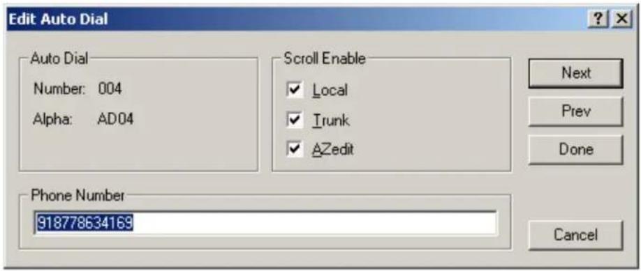
- From the Scroll Enable group box, select the scroll enable check boxes you want to configure for the auto dial number.
- In the Phone Number field, enter the telephone number you want to have for that auto dial sequence.
NOTE: Entering *99 creates a pause in dialing. This is used to dial extensions or select preset options.
- Click Next to enter another number.
The next blank Edit Auto Dials window appears.
OR
Click Done to close the Edit Auto Dial window.
The Auto Dials window appears with the new number in the list.
To add a description to the telephone number you added to the Auto Dial database, do the following:
- From the Alphas menu in AZedit, select Auto Dial.
The Auto Dial Alphas window appears. - Double-click the AD resource number to which you want to add the description.
The Edit Alpha/Description window appears.
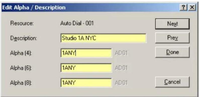
- In the Description field, enter a unique description for the auto dial number. For example, Studio 1A NYC.
-
In the Alpha 4, Alpha 6, or Alpha 8 field, enter a recognizable 4-, 6- or 8-character Alpha. For example, 1ANY.
-
Click Done when you are finished.
OR
Click Next to enter another Alpha Description.
![AZedit - [ONLINE] - Auto Dials File Online Authentication Edit View System Alphas Status Options Logging Help Auto Dial ▲ Alpha LC Phone Number 001 AD01 LC 002 AD02 LC 3910 003 AD03 LC 3911 004 AD04 LC 93175551212 005 AD05 LC 006 AD06 LC 007 AD07 LC 008 AD08 LC 009 AD09 LC 010 AD10 LC](/content/2026/05/1012724/images/bf01faa045560abcb7cb1282b0fe1e99f730b6a8b73ea5681ae291204f72ee58.jpg)
- From the Online menu in AZedit, select Send Changes.
The Send Changes window appears.
- Click OK.
The changes are sent to the intercom and the telephone number is added to the intercom system auto dial table.
To use centralized auto dial numbers, do the following:
- On the keypanel, press the TIF assignment key.
Hang Up, Icom ADial, Manual Dial, and Redial appear in the panel display.
-
Using the arrow buttons, scroll to Icom ADial.
-
Press the SEL button.
You enter the centralized auto dial list. A scrollable list of available Auto Dial numbers appear in the panel display.
-
Using the arrow buttons, scroll to the desired auto dial number.
-
Press the SEL button.
The number connects.
To use centralized auto dial numbers with keypanel keypad sequences, do the following:
- Press the SHIFT + DIAL keys.
Tap Key appears in the panel display.
- Press the TIF assignment key.
A dial tone is heard.
- Using the keypad, enter #NNN (where NNN is the Auto Dial number assignment in AZedit).
The number is dialed.
Keypad Sequence Introduction
Keypad sequences are a series of keypad strokes made on the keypanel, which in turn displays specific information (such as keypanel ID, talk level 2 assignments, etc.). Keypanel sequences are shortcuts via the keypanel keypad.
As with other keypanels, the KP-5032/4016Series allows you to lock the entire menu or only the service menu. This is implemented through AZedit (System|Miscellaneous|Keypanel Menu Password). For more information, see the AZedit user manual (p/n F01U239453).
Keypad Sequences


| Keypad Description | |
| MENU Open the main menu | |
| FWD Move one selection forward through highlighted menu option | |
| BACK Move one selection backwards through highlighted menu option | |
| LOC Display a list of available intercoms available to scroll from | |
| Arrow Up Scroll upward through scroll list or available key assignments one at a time | |
| Arrow Left Move backwards through menu options or available key assignments one at a time | |
| MENU (middle of the keypad) Open the main menu | |
| Arrow Right Move forward through menu options or available key assignments one at a time | |
| COPY Copy incoming call key assignment from the CWW | |
| Down Arrow Scroll downward through scroll list or available key assignments one at a time | |
| PAGE Access setup pages | |
| CLR Clear the CWW (Acts as a BACK button in menu mode, or by holding it down, exits the menu structure.) | |
| SHIFT Access secondary keypad actions | |
| SEL | Select options highlighted in a menu |
| SHIFT+LOC | Displays the keypanel assignment types |
| SHIFT+4 | Move backwards through menu options or available key assignments a page at a time |
| SHIFT+INFO | Open the INFO menu |
| SHIFT+6 | Move forward through menu options or available key assignments a page at a time |
| SHIFT+DROP, | Hang up TIF on key |
| SHIFT+DIAL, | Enter dial mode on TIF on key |
| SHIFT+LSTN,(Pushbutton models only) | Listen mode activated |
| SHIFT+(Pushbutton models only) | Listen key activated |
IMPORTANT: When SHIFT +
| Keypad Sequences | |
| 7,Copy the CWW to a key | |
| 0,0,0,8,1 Show panel ID | |
| 0,0,0,8,2 Show talk level 2 assignments | |
| 0,0,0,8,3 Show listen assignments | |
| 0,0,0,8,7 Enable tonc | |
| 0,0,0,8,0 Enter test mode | |
| 0,0,3,1,SEL,Program a listen key with an AL assignment | |
| 0,0,3,2,SEL,Program a listen key with an AF assignment | |
| 0,0,3,3,SEL,Program a listen key with an AM assignment | |
| 0,0,3,4,SEL,Program a listen key with an AR assignment | |
| 0,0,3,7,SEL,Program a listen key with an AT assignment | |
| 0,0,3,5,SEL,Program a talk key with an AC assignment | |
| 0,0,0,8,8 Show setup pages | |
| 0,7,or 7, SEL,,Copy the first key to the second key | |
| 9,SELSelect setup page for row of keys | |
| 2 (up) or 4 (left) Enter scroll list mode, scroll up/left | |
| 8 (down) or 6 (right) Enter scroll list mode, scroll down/right | |
| The following sequences also require the assignments are marked as Local scroll enable in AZedit:NOTE: IFB, ISO, RY, and IFSL are not locally scrollable, by default. | |
| 0,0,1,SEL,Program a key with a port assignment | |
| 0,0,2,SEL,Program a key with a PL assignment | |
| 0,0,0,1,SEL,Program a key with a SL assignment | |
| 0,0,0,2,SEL, | Program a key with an IFB assignment |
| 0,0,0,3,SEL, | Program a key with an ISO assignment |
| 0,0,0,4,SEL, | Program a key with an RY assignment |
| 0,0,0,5,2SEL, | Program a key with an IFB SL assignment |
Keypanel Menu Quick Reference
Audio Options
| Advanced | ||||
| AEC | ||||
| Mic Priority | ||||
| Front Mic (default) | ||||
| Rear Mic | ||||
| AGC | ||||
| Attack | ||||
| Front Hdst Front Mic Rear Hdst Rear Mic | Fast Attack Speed | 0.5ms 1ms (default) 2ms | ||
| Decay | ||||
| Front Hdst Front Mic Rear Hdst Rear Mic | Decay | 500ms (default) 750ms 1000ms | ||
| Compression | ||||
| Front Hdst Front Mic Rear Hdst Rear Mic | Compression Ratio: | 1:1 2:1 3:1(default) 4:1 (only available with Audio Package) 5:1 (only available with Audio Package) 6:1 (only available with Audio Package) | ||
| Filters | ||||
| Bandpass | ||||
| Inputs | ||||
| Aux 1 Aux 2 OMNEO 1 OMNEO 2 OMNEO 3-8 (only available with Audio Package) | ||||
| Frequencies | |||
| Low Freq | 0 Hz (default)15.6Hz31.5Hz50Hz | ||
| High Freq | 22kHz (default)16kHz8KHz4KHz | ||
| Mode | |||
| Disabled (default) | |||
| Enabled | |||
| Outputs | |||
| Front Hdst Rear Hdst | Both Left Chan Right Chan | ||
| Frequencies | |||
| Low Freq | 0 Hz (default)15.6Hz31.5Hz50Hz | ||
| High Freq | 22kHz (default)16kHz8KHz4KHz | ||
| Mode | |||
| Disabled (default)Enabled | |||
| Matrix Out OMNEO 1 OMNEO 2 OMNEO 3-8 (only available with Audio Package) Preamp Out | |||
| Frequencies | |||
| Low Freq | 0 Hz (default)15.6Hz31.5Hz50Hz | ||
| High Freq | 22kHz (default)16kHz8KHz4KHz | ||
| Mode | |||
| Disabled (default)Enabled | |||
| Equalization | ||||
| Inputs | ||||
| Front Hdst Front Mic Matrix In Rear Hdst Rear Mic | Modes | Disabled (default) Enabled | ||
| Presets | Default (default) Hiss Reduction Noise Reduction Rumble Reduction | |||
| Outputs | ||||
| Front Spkr Rear Spkr | Modes | Disabled (default) Enabled | ||
| Presets | Default (default) Hiss Reduction Noise Reduction Rumble Reduction | |||
| Notch | ||||
| Notch Filter | ||||
| Disabled (default) Narrow Default Wide | ||||
| Gating | ||||
| Aux 1 Aux 2 Front Hdst Front Mic Matrix In OMNEO 1 OMNEO 2 OMNEO 3-8 (only available with Audio Package) Rear Hdst Rear Mic | ||||
| Threshold | ||||
| Disabled (default) -17dB – 18dB | ||||
| Metering | ||||
| Aux 1 Aux 2 Front Hdst Front Mic Matrix In None (default) OMNEO 1 OMNEO 2 OMNEO 3-8 (only available with Audio Package) Rear Hdst Rear Mic | ||||
| Mixing | |||
| Front HdstRear Hdst | BothLeft ChanRight Chan | Aux 1Aux 2Front HdstFront MicOMNEO 1OMNEO 2OMNEO 3-8 (only available with Audio Package)Rear HdstRear Mic | |
| Front SpkrOMNEO 1OMNEO 2Rear Spkr | Aux 1Aux 2Front HdstFront MicMatrix InOMNEO 1OMNEO 2OMNEO 3-8 (only available with Audio Package)Rear HdstRear Mic | ||
| Preamp OutTo Matrix | Aux 1Aux 2Matrix InOMNEO 1OMNEO 2OMNEO 3-8 (only available with Audio Package) | ||
| Mix Mode | |||
| Aux Mixes Switched (default) | |||
| Mixes Always Active | |||
| Noise Gate | |||
| Front Hdst | Disabled (default)Enabled | ||
| Front Mic | |||
| Rear Hdst | |||
| Rear Mic | |||
| Chime | |||
| Preview | |||
| Yes (default)No | |||
| Chime | |||
| System #1-8 (User #1-4 with Audio package) | |||
| Volume | |||
| -20dB (default)-60dB – 10dB | |||
| Dim | |||
| Headset | |||
| FrontRear | DimAmount: | 0dB (default)-32dB – 0dB | |
| Speaker | |||
| FrontRear | DimAmount: | -8dB (default)-48dB – 0dBMute | |
| Ganged Vols | ||||
| Disappearing (default)Fixed Offset | ||||
| Headset Mic | ||||
| Front | Auto-Mute | DisabledEnabled (default) | ||
| Mode | DisabledEnabledSwitched (default) | |||
| Type | Auto-Detect (default)DynamicElectret | |||
| Rear | Auto-Mute | DisabledEnabled (default) | ||
| Mode | Disabled (default)EnabledSwitched | |||
| Type | Auto-Detect (default)DynamicElectret | |||
| Headset Spkr | ||||
| Front | Auto-Transfer | DisabledEnabled (default) | ||
| Mode | Both,Left ChanRight Chan | Always On (default)DisabledSwitched | ||
| Rear | Auto-Transfer | DisabledEnabled (default) | ||
| Mode | Both,Left ChanRight Chan | Always On (default)DisabledSwitched | ||
| Volume Control | ||||
| GangedIndividual (default) | ||||
| Inputs | ||||
| Aux 1 | ||||
| DisabledEnabled (default) | ||||
| Aux 2 | ||||
| DisabledEnabled (default)Ganged | ||||
| Matrix In | ||||
| DisabledEnabled (default) | ||||
| OMNEO 1 | ||||
| DisabledEnabled (default) | ||||
274 Keypanel Menu Quick Reference KP Series
| OMNEO 2 | |||
| DisabledEnabled (default) | |||
| OMNEO 3 | |||
| DisabledEnabled (default) | |||
| OMNEO 4 | |||
| DisabledEnabled (default)Ganged | |||
| OMNEO 5 | |||
| DisabledEnabled (default) | |||
| OMNEO 6 | |||
| DisabledEnabled (default)Ganged | |||
| OMNEO 7 | |||
| DisabledEnabled (default) | |||
| OMNEO 8 | |||
| DisabledEnabled (default)Ganged | |||
| Key Volumes | |||
| Adjust | |||
| DisabledEnabled (default) | |||
| Minimum | |||
| Adjust Minimum Key Volumes | |||
| Reset | |||
| CancelDo Reset | |||
| Volumes Reset | |||
| LCP 16 CLD | |||
| Encoder #1 – #16 | |||
| Inputs | Aux 1Aux 2Matrix InOMNEO 1OMNEO 2OMNEO 3-8 (only available with Audio Package) | ||
| Outputs | Both HdstsBoth SpkrsFront HdstFront SpkrRear HdstRear Spkr | ||
| Sidetone | |||
| Unassigned (default) | |||
| Matrix Out | |||
| Hot Mic | |||
| Normal (default) | |||
| Max Volume | |||
| Headset | Front | Max Volume: -48dB – 10dB (default), Mute | |
| Speaker | Rear | ||
| Mic Gain | |||
| Adjust | |||
| Disabled (default) | |||
| Front Hdst | |||
| Front Mic | |||
| Rear Hdst | |||
| Rear Mic | |||
| Level | |||
| Front Hdst | Mic Gain: | ||
| Front Mic | 0dB (default) | ||
| Rear Hdst | -20dB – 10dB | ||
| Rear Mic | |||
| Mic Mute | |||
| Disabled | |||
| Momentary | |||
| Toggle (default) | |||
| Min Volume | |||
| Headset | Front | Min Volume: | |
| Speaker | Rear | -6dB (default for Matrix IN) Mute (default for all others) | |
| Aux 1 | -48dB – 10dB | ||
| Aux 2 | |||
| Matrix In | |||
| OMNEO 1 | |||
| OMNEO 2 | |||
| OMNEO 3-8 (only available with Audio Package) | |||
| Output Level | |||
| Output Level: | 8dB (default) – 0dB | ||
| Panel Mic | |||
| Front | Disabled | ||
| Enabled | |||
| Switched (default) | |||
| Rear | Disabled (default) | ||
| Enabled | |||
| Switched | |||
| Preamp Out | |||
| Disabled | |||
| Hot Mic | |||
| Invert | |||
| Switched (default) | |||
| Sidetone | |||
| Level | |||
| Sidetone Level: -20dB (default), -65dB to 0dB | |||
| Mode | |||
| Always On | |||
| Disabled | |||
| Switched (default) | |||
276 Keypanel Menu Quick Reference KP Series
| Speaker | ||
| Front | Always OnDisabledSwitched (default) | |
| Rear | Always OnDisabled (default)Switched | |
| VolumeControl | GangedIndividual (default) | |
| Tone Gen | ||
| Frequency | 1KHz Tone500Hz Tone (default) | |
| Tone Off (default) | ||
| Tone On | ||
| VM Options | ||
| Playback | ||
| IsolateMix (default) | ||
| Recording | ||
| Auto Recording | ||
| Disabled (default)Rolling Buffer | ||
| When Mailbox Full | ||
Display Menu
| Assign Type | |
| Shows key's assignment types | |
| Auto Dial | |
| Shows keys with 1-Touch Auto Dial assigned | |
| Chans On | |
| Shows scroll list of current callers | |
| Chime | |
| Shows keys with Chime assigned | |
| Exclusive | |
| Shows which keys are Exclusive keys | |
| Key Groups | |
| Group 1 - shows which key is Master, and which keys are Group SlavesGroup 2 - shows which key is Master, and which keys are Group SlavesGroup 3 - shows which key is Master, and which keys are Group SlavesGroup 4 - shows which key is Master, and which keys are Group Slaves | |
| Key List | |
| Shows scroll list of hidden key assignments assigned to virtual keys | |
| LCP 16 CLD | |
| LCP 16 CLD Assigns *displays “LCP not detected” if none are attached | |
| Level 2 | |
| Level 2 Assignments - Shows the talk level 2 assignment for each key assignment | |
| Listen | |
| Listen Assignments - Shows the listen assignment for each key assignment | |
| MAC Address | |
| MAC Address - Displays the MAC Address for the keypanel. | |
| Matrix | |
| Key Assignment Matrices - Shows the matrix for each key assignment | |
| Panel ID | |
| - Shows the port number and alpha for this keypanel | |
| Solo Key | |
| Solo Keys - Shows which key is the solo key | |
| Version | |
| Version X.X.X - shows the keypanel firmware version | |
Key Assign Menu
| Matrix (only displays if there are remote matrices.Selecting Matrix displays a list of remote intercoms.) | ListenTalk Lvl1Talk Lvl2Talk+AFTalk+ALTalk+AMTalk+ARTalk+AT | Tap Key | |
| Pt-to-Pt | |||
| Party Line | |||
| IFB | |||
| Special List | |||
| Sys Relay | |||
| Camera ISO | |||
| UPL Resource | |||
| IFB Spcl List | |||
| Auto Funcs | All CallAuto FollowAuto ListenAuto MuteAuto RecipAuto TableDIM | Tap Key | |
Key Options Menu
| Auto Dial | ||
| Numbers | ||
| #01 - #100 | ||
| 1-Touch | ||
| Tap Key | ||
| Chime | ||
| Chime | ||
| System #9 | ||
| System #10 | ||
| System #11 | ||
| System #12 | ||
| User #1(with Audio Package) | ||
| User #2 (with Audio Package) | ||
| User #3 (with Audio Package) | ||
| User #4 (with Audio Package) | ||
| Duration | ||
| One-shot (default) | ||
| 1 second | ||
| 2 seconds | ||
| 3 seconds | ||
| 4 seconds | ||
| 5 seconds | ||
| 10 seconds | ||
| 15 seconds | ||
| 20 seconds | ||
| 30 seconds | ||
| 60 seconds | ||
| 90 seconds | ||
| 2 minutes | ||
| 3 minutes | ||
| 4 minutes | ||
| 5 minutes | ||
| Clear | ||
| Tap Key | ||
| Exclusive | ||
| Tap Key | ||
| Icons | ||
| Icon | ||
| Key has TIF Asgn | ||
| Key is Solo Key | ||
| Key is Exclusive Key | ||
| Key has Auto-Dial | ||
| Key is Group Master | ||
| Key has Chime | ||
| Key has Trunk Asgn | ||
| Display | ||
| Disabled | ||
| Enabled (default) | ||
| Key Groups | ||
280 Keypanel Menu Quick Reference KP Series
| Group 1 | Tap Master Key | Tap Slave Key | |||
| Group 2 | |||||
| Group 3 | |||||
| Group 4 | |||||
| Latching | |||||
| Global | |||||
| Disabled | |||||
| Enabled (default) | |||||
| Per Key | |||||
| Tap Key | |||||
| Lock | |||||
| Tap Key | |||||
| Panel Swap | |||||
| Control | |||||
| GPI Inputs | |||||
| Opto 1 Opto 2 | |||||
| GPI Outputs | |||||
| Relay 1 Relay 2 | |||||
| Back FWD UPG 1 - UPG9 | |||||
KP Series Keypanel Menu Quick Reference 281
| Tallies | ||
| Indefinite | ||
| Disabled (default) | ||
| Enabled | ||
| Min Duration | ||
| Min Duration: | ||
| 5 seconds | ||
| All Keys | ||
| Turn Keys Off? | ||
| Keys Turned Off | ||
| 5 seconds | ||
OMNEO Offers Menu
| Keypanel | |
| OKP | |
| AIO - If an RVON-IO or an OEI-2 is connected, it shows that device instead | |
| Aux Input | |
| OMNEO 1 | |
| OMNEO 2 | |
| OMNEO 3 | |
| OMNEO 4 | |
| OMNEO 5 | |
| OMNEO 6 | |
| OMNEO 7 | |
| OMNEO 8 | |
Save Config Menu
Configuration Saved
Service Menu
| Alphas | ||
| 4 Chars (default) | ||
| 6 Chars | ||
| 8 Chars | ||
| 8 Chars (Unicode) | ||
| Aux Select | ||
| Number of Analog Inputs 0 | ||
| Number of Analog Inputs 1 | ||
| Number of Analog Inputs 2 | ||
| CWW | ||
| Number of Entries | ||
| 3 through 9 | ||
| On New Caller | ||
| Don't Select | ||
| Select If Idle | ||
| Select New Call | ||
| Display | ||
| Menu Context | ||
| Disabled | ||
| Enabled (default) | ||
| Show Volume | ||
| Disabled (default) | ||
| Enabled | ||
| KP32 Emulation | ||
| Disabled (default) | ||
| Enabled | ||
| Footswitch | ||
| Mode | ||
| Disabled (default) | ||
| Enabled | ||
| Latched Keys | ||
| Retain (default) | ||
| Unlatch | ||
| Intercom Mode | ||
| Alternate | ||
| Standard (default) | ||
| Key View | ||
| Show Gain | ||
| Disabled (default) | ||
| Enabled | ||
| Show Lstn | ||
| Disabled (default) | ||
| Enabled | ||
| Enabled (Suppress Auto) | ||
| Show Mtx | ||
| Disabled (default) | ||
| Enabled | ||
| Enabled (Suppress Local) | ||
284 Keypanel Menu Quick Reference KP Series
| Keypad | ||||
| SEL Key | ||||
| Auto (default)Assign GroupsQuick Assign | ||||
| Backlight | ||||
| Activation | ||||
| Activate | ||||
| On Keypress (swallowed) (default) | ||||
| On Keypress (processed) | ||||
| Always | ||||
| Never | ||||
| Setup | ||||
| Inactive | ||||
| Brightness: ##% (default is 30%) | ||||
| Color: | ||||
| Blue (default) | ||||
| White | ||||
| Active | ||||
| Brightness: ##% (default is 100%) | ||||
| Color: | ||||
| Blue (default) | ||||
| White | ||||
| Shift State | ||||
| Brightness: ##% (default is 100%) | ||||
| Color: | ||||
| Blue | ||||
| White (default) | ||||
| LCD Backlight | ||||
| All Panels | ||||
| Brightness:65% (default)35% - 100% | ||||
| Main Panel | ||||
| Both, Left, Right | ||||
| Brightness:65% (default)35% - 100% | ||||
| EKP 1 – 7 | ||||
| Both, Left, Right | ||||
| Brightness:65% (default)35% - 100% | ||||
| Local GPIO | ||||||
| GPIO Inputs | ||||||
| Opto1 Opto2 | Function | Key Group | Group 1 Group 2 Group 3 Group 4 | Level Cancel Save and Restart | ||
| Edge Cancel Save and Restart | ||||||
| Not Assigned (default) | ||||||
| Talk Key Tap Key | ||||||
| Mode | Normal (default) Track Output | |||||
| GPIO Outputs | ||||||
| Relay 1 Relay 2 | Not Assigned (default) | |||||
| Talk Key Tap Key | ||||||
| UPG1 – UPG9 | ||||||
| Mirror | ||||||
| OMNEO Setup | ||||||
| OKP OEI-2 (if attached) | ||||||
| Device Name | ||||||
| DHCP | ||||||
| Disabled (default) Enabled | ||||||
| IP Parameters | ||||||
| IP AddressNetmaskGatewayDNS Server 1Domain | ||||||
| Page Change | ||||||
| Auto (default) Always Allow No Talk Keys | ||||||
| Reset Cfg | ||||||
| Cancel Do Reset | ||||||
| Configuration Reset | ||||||
| Scrn Saver | ||||||
| Activate | ||||||
| Delay | ||||||
| Display Dim | ||||||
| Delay Time: 1 | hour (default) (30 min, 1 – 12 hours, and Disabled) | |||||
| Activation | ||||||
| Delay Time: 1 | hour (default) (30 min, 1 – 12 hours, and Disabled) | |||||
| Display Dim | ||||||
| Brightness: 25% (default) (0% – 100%) | ||||||
| Mode | ||||||
| Bitmap | ||||||
| Bounce Scroll (default) | ||||||
286 Keypanel Menu Quick Reference KP Series
| Display Off | |||
| Text (default) | |||
| BounceScroll (default) | |||
| Set Address | |||
| Poll ID <1-8> | |||
| Cancel | |||
| Save and Restart | |||
| Snoop Tally | |||
| Chime: | |||
| none (default), System #1 through System #8 (User #1 through 4 with Audio package) | |||
| Duration: | |||
| One-shot (default) (1 sec, 2 sec, 3 sec, 4 sec, 5 sec, 10 sec, 15 sec, 20 sec, 30 sec, 60 sec, 90 sec, 2 min, 3 min, 4 min, 5 min) | |||
| Test Panel | |||
Introduction
Connecting directly to the KP-4016/5032 color keypanel, the EKP-4016 (Expansion Panel Color Display) provides an additional 16 keys per expansion panel to your intercom application.
Refer to Figure 93, "Expansion Panel Cabling," on page 290, for information on how to connect up to six additional expansion panels (if the intercom is configured for 128 keys) with a KP-5032, or seven additional expansion panels (if the intercom is configured for 128 keys) with a KP-4016.
IMPORTANT: The keypanels or the expansion panels can be either lever key or pushbutton.
Specifications
LCD Display
Active Area
120.10mm (wide) x 18.77mm (high)
Dot Resolution
576 x 90 dots
Color Resolution
16-bit (64K) RGB color
View Angle
80 degrees (typical; all directions)
Connector
EXP IN RJ-45
EXP OUT RJ-45
General
EKP-4016
Storage Temperature
-40°C to 70°C (-40°F to 158°F)
Operating Temperature
0^ to 55^ (32^ to 131^)
Dimensions
17.39"L x 1.72"H x 3.92"D (441.82mm x 43.8mm x 99.5mm)
Weight
2.91lb (1.32kg)
Power Consumption
Nominal - 6 Watts
Maximum - 7 Watts
Maximum Volt Amp - 48VA
Input Power
100\~240VAC, 50–60Hz
EKP-4016 Expansion Panel
Reference View

FIGURE 92. EKP-4016 Expansion Panel Reference View – Front and Rear (EKP-4016PB shown in inset)
- Expansion Keys
- Power
- Power Supply Bracket Mounting Holes
- RJ-45 Expansion IN
- RJ-45 Expansion OUT
- Power Supply Cable Tie Mounting Hole
Expansion Panel Cabling Reference
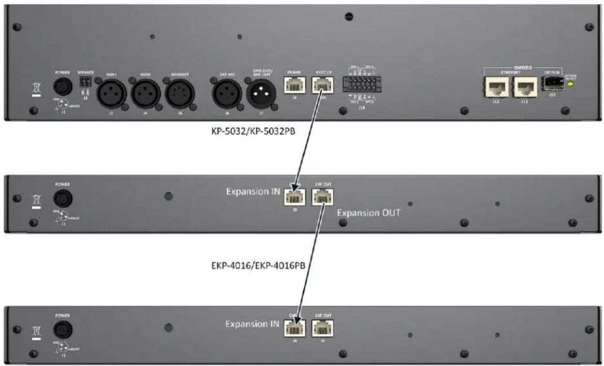
FIGURE 93. Expansion Panel Cabling
| RJ-45 EXP IN (expansion) | |
| Pin Assignment | |
| 1 No Connect | |
| 2 | NC |
| 3 | NC |
| 4 | NC |
| 5 | NC |
| 6 | NC |
| 7 RS485 + | |
| 8 RS485 - | |
| RJ-45 EXP OUT (expansion) | |
| Pin Assignment | |
| 1 | NC |
| 2 | NC |
| 3 | NC |
| 4 | NC |
| 5 | NC |
| 6 | NC |
| 7 RS485 + | |
| 8 RS485 - | |
AZedit and Unicode Support
Minimum firmware revision requirements for Unicode support are:
• MCII-e v2.4.0 or later
• AIO-8 v10.5.0 or later
• AIO-16 v1.3.0 or later
• Cronus v1.8.0 or later
- Zeus III v1.3.0
- KP 32 CLD v1.3.0 or later
- KP 12 CLD v1.1.0
- RP-1000 v2.0.0
• KP12/4U v1A.0.26 (Cyrillic character set only)
KP-5032/4016 v1.1.1
To configure the keypanel for Unicode operation, do the following:
- On the keypanel, select Service|Alphas|8 Chars (Unicode)|Save and Restart.
NOTE: If using the keypanel with Japanese firmware, you must also configure the correct Intercom Mode. See "Service Menu, Intercom Mode" on page 241.
- From the Options menu in AZedit, select Preferences.
The Application Preferences window appears.
- Select the Advanced tab.
The Advanced page appears.
- Select the Allow intercom resizing in ONLINE mode check box.
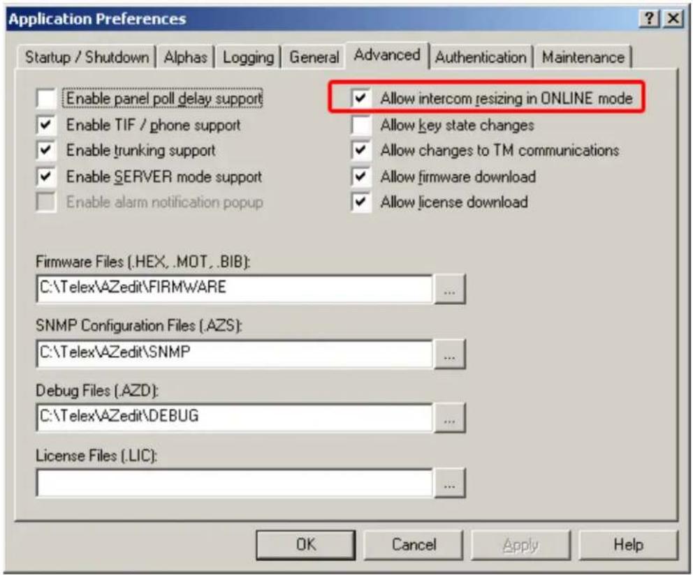
-
Click Apply.
-
Click OK.
The Application Preferences window closes.
IMPORTANT: You are about to erase the entire intercom setup! Be sure to save your file.
- From the Options menu, select Intercom Configuration.
The Intercom Configuration window appears.
- Click the Options tab.
The Options page appears.
- Select the Enable Unicode Alphas check box.

- Click Apply.
The Intercom Configuration window closes.
- From the Options menu, select Preferences.
The Application Preferences window appears.
- Click the Alphas tab.
The Alphas window appears.
- From the Preferred alpha size drop down menu, select 8-UNICODE characters.

- Click Apply.
- Click OK.
The Application Preference window closes.
To restore the system configuration, do the following:
- From the Online menu, select Send File.
- Navigate to the system configuration file (.adm) you want to restore.
- Click OK.
Power Supply Mounting Options
Power Supply Mounting Bracket Instructions
IMPORTANT:
The KP-4016/4016PB power supply can only be mounted directly into a rack and cannot have the power supply mounted to the unit.
Mounting the Power Supply to KP-5032/5032PB Unit
To mount the power supply mounting bracket to a KP-5032/5032PB, do the following:
- Align the power supply mounting bracket screw holes with the appropriate mounting holes on the rear panel of the KP-5032/5032PB unit.
- Using a screwdriver, attach the power supply mounting bracket with the two supplied screws.

Mounting Screws
- Attach the power supply cable tie clip to the predefined clip mounting hole on the rear of the keypanel unit.
- Attach the DC power connector to the unit.
-
Carefully thread the power cable through the bracket, in order to utilize the power supply cable tie.
-
From the left-hand side of the mounting bracket, carefully slide the power supply into the bracket.

- Carefully coil the power supply cord and insert it into the cord clip.

natural_image
Technical line drawing of a mechanical assembly with internal components and connector layouts (no text or symbols)- Attach the AC power connector to the power outlet on the power supply.

- Plug the power cord into an electrical outlet.
Mounting the Power Supply to EKP-4016/4016PB Unit
To mount the power supply mounting bracket to an EKP-4016, do the following:
- Align the power supply mounting bracket screw holes with the appropriate mounting holes on the rear panel of the EKP-4016 unit.
- Using a screwdriver, attach the power supply mounting bracket with the two supplied screws.
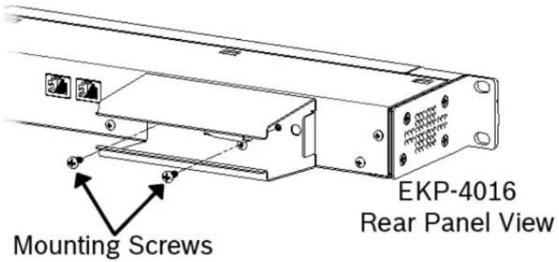
- Attach the power supply cable tie clip to the predefined clip mounting hole on the rear of the keypanel unit.
- From the left-hand side of the mounting bracket, carefully slide the power supply into the bracket.
NOTE: The Frame and EXP OUT connections cannot be populated until the power supply mounting bracket is fully installed.
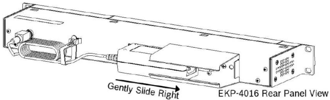
-
Attach the DC power connector to the unit.
-
Carefully coil the power supply cord and insert it into the cord clip.
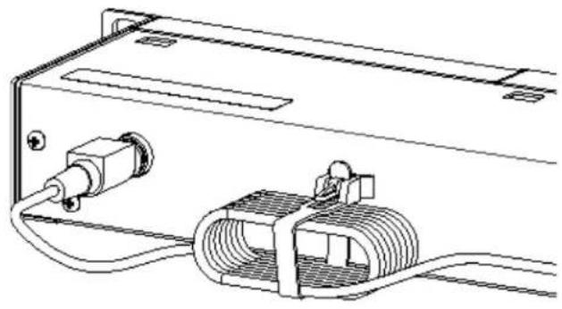
natural_image
Technical line drawing of an electronic device with a coiled cable and connector (no text or symbols)EKP-4016 Rear Panel View
- Attach the AC power connector to the power outlet on the power supply.

natural_image
Technical line drawing of an electronic device with ports, cables, and connectors (no text or symbols)- Plug the power cord into an electrical outlet.
Mounting the Power Supply to a Standard Rack
The Power Supply Mounting bracket can be directly attached to a standard rack, horizontally or vertically as shown in Figure 94 and Figure 95.

natural_image
Technical line drawing of a mechanical assembly with a coiled spring and housing (no text or symbols)FIGURE 94. Mounting Bracket – Horizontal on a Crossbar
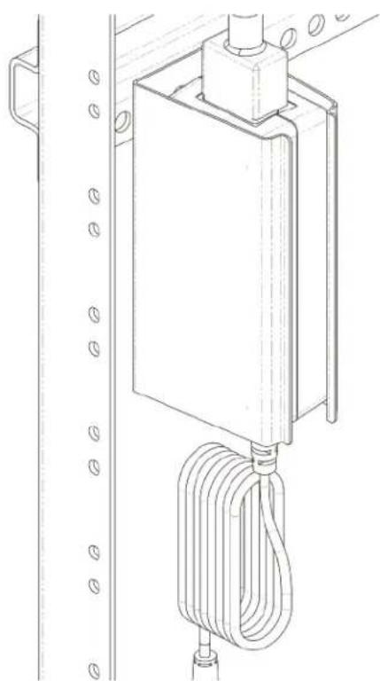
natural_image
Technical line drawing of a mechanical device with coiled cable and mounting bracket (no text or symbols)FIGURE 95. Mounting Bracket – Vertical from a Crossbar
Audio and Control Add-On Package
The Audio and Control Add-On Packages for the KP Series keypanels greatly expand your keypanel and intercom system experience and capabilities. The Audio part of the package delivers voice messaging for when a user has stepped away from a panel, additional OMNEO channels, additional equalization bands, and adjustable compression and noise gating. The Control part of the package offers real-time control of keypanels from AZedit as well as from another keypanel. It also offers KP Configuration from AZedit, allowing you to upload a keypanel configuration from one keypanel, make changes to the configuration and then download it to one or multiple licensed keypanels across your system. In addition, it includes two ways of customizing the keypanel with downloadable chimes and downloadable screen savers.
Below is a chart detailing what is included with each package.
Audio Package Control Package
| Additional OMNEO Channels 3 – 8Voice Messaging (See “Voice Messaging (Audio Package Only)” on page 68.)Adjustable Compression (See “Compression” on page 189.)Adjustable Noise Gating (See “Noise Gate – Audio Package Only” on page 199.)5-band Equalization (See “Adjustable 5-Band Equalization – Audio Package Only” on page 192.) | Downloadable Screen Saver (See “Download Screen Savers (Control Package Only)” on page 181.)Real-time Control (See “Real-Time Control in AZedit (Control Package Only)” on page 99.)Keypanel Mirroring Mode (See “Keypanel Mirroring (Control Package Only)” on page 96.)Keypanel Configuration (See “Keypanel Configuration (Control Package Only)” on page 109.)Downloadable Chimes (See “Download User Chimes (Control Package Only)” on page 179.) |
IMPORTANT:
| If you are upgrading the KP-4016/5032 from version 1.1.1 or earlier to version 1.2.0 or later, you must do the following: ·Download the Firmware ·Download the License, if purchased. ·Download the Voice Mail Chimes (downloaded with vm-chimes.mot) ·Download the Voice Mail Icons (downloaded vm-icons.mot) |
For more information on downloading firmware, see “Download Firmware to the Keypanel From AZedit” on page 161.
Take note, the VM chimes and VM icons are .mot files ad should be treated as firmware downloads, not Chimes or Icons.
Panels shipped from the factory with v1.2.0 or higher, include VM Chimes and VM icons.
Download License Files
License files activate the packages you have purchased. Similar to firmware files, license files are downloaded to the keypanel via AZedit; unlocking the intended features
To download/activate license files, do the following:
-
Open AZedit.
-
From the Status menu, select Software Versions|Keypanels.
The Keypanel Version Information window appears.
-
Select the port number where the keypanel with the license is located.
-
Highlight the Port (keypanel) to be updated.
You may select more than one at a time by holding CTRL key down while you select. But, you must make sure every MAC ID matches before downloading.
IMPORTANT: To find the MAC Address of the keypanel, do one of the following:
• Find it in IPedit
• Find it in the Display menu at "Display Menu, MAC Address" on page 216
• Find it in the Info menu at "INFO button" on page 46
![AZedit - [ONLINE] - Keypanel Version Information File Online Authentication Edit View System Alphas Status Options Logging Help Port / Alpha Version 061 N061 n/a 062 N062 n/a 063 N063 n/a 064 N064 KP-5032, Version 1.0.2, M Info 065 N065 n/a 066 N066 n/a 067 N067 n/a 068 N068 n/a 069 N069 n/a 070 N070 n/a 071 N071 n/a 072 N072 n/a Download firmware... Download font... Download splash screen... Download screen saver... Download icons... Download chime... Download keypanel configuration... Download license...](/content/2026/05/1012724/images/a82fa523a6cd95fee0b0226b5667245087b81a963337ed1923646782685be717.jpg)
- Right-click the highlighted selections.
A popup menu appears.
- Select Download license....
The License Download window appears.
- Navigate to the license file.
8. Click Open.
The Download License File window appears.

9. Click Begin Download.
The license file is downloaded and unlocks the licensed features purchased.
Once you have installed the package(s) you purchased, the following icon appears at power up for five seconds and then disappears.

Only the Audio Package is installed

Only the Control Package is installed

Both the Audio and Control Packages are installed
IMPORTANT: Devices can support either AES67 or ST-2110-30. Both modes cannot be active at the same time. This means a device can either support AES67 Tx and Rx streams or ST-2110-30 Tx and Rx streams, but not both.
To use ST-2110-30 you must first set the device mode to ST-2110-30 configure the device parameters for ST-2110-30 operation, and then set up Tx (transmit) flows and Rx (receive) channels. The Tx flows are what other devices on the network connect to, while Rx channels are what your device uses to connect to other devices on the network. Each Tx flow can connect to a maximum of eight channels.
Prerequisites
In order to use ST-2110, you must upgrade the following devices:
| Device Version | |
| ODIN V1.7.1 | |
| KP-Series V2.7.3 | |
| OMI V6.8.1 | |
| OKI V6.8.1 | |
| OEI-2 V2.8.1 | |
| OMS V1.1.0 | |
| AZedit V5.8.2 | |
| IPedit | V3.9.1 |
| Audio Device (Audinate) | V8.30.000 or above |
Operation
Set Device Parameters
Devices which support ST-2110-30 have the capability to set the ST-2110-30 mode.
To set the ST-2110-30 mode do the following'
IMPORTANT: All ST-2110 operations are supported via IPedit only.
-
From the Device menu, select Add. The Add Devices window opens.
-
Add the device to the catalog.
-
Select the ST-2110-30 tab.
-
From the Mode drop down menu, select ST-2110-30. The Mode options change causes the device to reset. The new mode is applicable after the device resets. Once the device is in ST-2110-30 mode, you can set the different RTP and PTPv2 settings.
-
Use Table 12 to see details for the RTP parameters.
TABLE 12. RTP Parameters
| Parameter Default Value Description | ||
| Mode Disabled Use the Mode field to select the mode | the device runs. Once the mode is enabled, then Tx and Rx streams can be created.Available options for this field:Disabled, ST-2110-30, and AES67.Changing this parameter causes the device to reset. | |
| Address Prefix 239.69.0.0 | The address prefix (first two bytes of the multicast IP address) field is used for incoming ST-2110-30 streams on the device.NOTE:The second byte may not be 0, this is not supported by the Dante layer.It is advised to set the Address Prefix of all OMNEO and Dante devices in a system to the same value, and to make sure all ST-2110-30 streams in that system use this prefix - also that of 3rd party devices. If that is not the case the OMNEO and Dante devices will not be able to receive all ST-2110-30 streams properly. | |
| SMPTE Mode 48 samples | (1 ms) The ST-2110-30 transmit flow packet time specified in 'frames per packet'(samples per packet). This defines the time needed to collect the samples into a transmit packet.Note that the sample rate is always 48 kS/s since Audinate only supports this sample rate for ST-2110-30 (and AES67).By default, this parameter has value 48, i.e (48 / 48000) = 1 ms. If it is changed new ST-2110-30 transmit streams will always use this value.There are only two supported values: 48 (1 ms) and 6 (125 us). | |
- Use Table 13 to see details for the PTPv2 parameters.
TABLE 13. PTPv2 Parameters
| Parameter Default Value | Description | |
| PTPv2 Leader | Follower | Use the PTPv2 Leader check box to define if the device is the PTPv2 Leader or if the device is the PTPv2 Follower.Select the check box to make this device the Leader.By default, this check box is not selected.NOTE: A PTPv2 clock master must be present on the network. |
| Priority 1 | 247 | Use the Priority 1 field in the PTPv2 announce messages of the device to determine the clock master. The lower the value the higher the priority.If in Follow-only mode, the device does not announce and this value is not needed. |
| Priority 2 | 116 | Use the Priority 2 field in the PTPv2 announce messages of the device to determine the clock master. The lower the value the higher the priority.If in Follow-only mode, the device does not announce and this value is not needed. |
TABLE 13. PTPv2 Parameters
| Parameter Default Value | Description |
| Domain Number 0 The PTPv2 domain number is used in all PTPv2 messages of the device (shown as sub-domain number field). The domain number defines in what PTPv2 domain the device will participate. This is useful if devices must synchronize to a PTPv2 master clock that uses a certain domain number in a system. The Domain Number also allows multiple PTPv2 domains to exist in a single system.You must set all devices that synchronize to a certain PTPv2 clock to the same number.NOTE:Configuring different Domain Number values for different devices means that the devices will not be synchronized to each other. | |
| Sync Interval 250 ms Use the Sync Interval to set the time between PTPv2 Sync messages. This is set on the PTPv2 clock master.The default is 250 ms.Available options for this field are: 250 ms, 0.5 sec, and 1 sec.If in Follow-only mode, the device does not announce and this value is not needed. | |
| Announce Interval 1000 ms Use the Announce Interval to set the amount of time between PTPv2 Announce messages. This set on the PTPv2 clock master.The default is 1000 ms.Available options for this field are: 250 ms, 500 ms, and 1000 msIf in Follow-only mode, the device does not announce and this value is not needed. | |
| Multicast Port TTL 16 Use the Multicast TTL to define how many routers messages can cross before being dropped. If you set this value to 1, PTPv2 traffic never leaves the subnet the device is in.The default is 16.This field ranges from 0 to 255.NOTE:This value matters on both the master and the follow-only devices since slave-only devices send PTPv2 DELAY_REQUEST messages. | |
Setting up a ST-2110-30 Tx (Transmit) Audio Stream
Channels that are ST-2110-30 enabled are available for ST-2110-30 Tx and Rx streams.
When the device is rebooted/restarted, if a valid Tx stream configuration is available, then the Tx stream is created.
To create a Tx Flow, do the following:
- In IPedit, select the device you want to set up a Tx audio stream.
| OMNED ST-2110 Rx ST-2110 Tx | Channels 1-8 | |||||||
| Channel 1 | Channel 2 | Channel 3 | Channel 4 | Channel 5 | Channel 6 | Channel 7 | Channel 8 | |
| Channel Configuration | ||||||||
| STQ110 Enabled | 区 | 区 | 区 | 区 | 区 | 区 | 区 | 区 |
| Intercom Alpha | ||||||||
| Channel Description | ||||||||
| Destination Type | Other | Other | OMI-16 | OMI-16 | OMI-16 | OMI-16 | OMI-16 | OMI-16 |
| Destination Device Name | SLOT7.local | |||||||
- On the OMNEO tab, select the ST-2110-30 check box for every channel you want enabled. A ST-2110-30 Tx tab appears.
IMPORTANT: Tx streams are known as ST-2110-30 flows. Each flow can have up to a maximum of eight channels.
TABLE 14. Maximum number for flows supported by RTS OMNEO devices
| Device Maximum number of flows | |
| ODIN 128 | |
| OMI 48 | |
| OKI 2 | |
| OEI-2 2 | |
| KP-Series 2 | |
| OMS 64 | |
- Select the flow you want to create.
| OMNEO | ST-2110 Rx | ST-2110 Tx | Flows 1-16 | Flows 17-32 | Flows 33-48 | Flows 49-64 | ||
| Flow 1 | Flow 2 | Flow 3 | Flow 4 | |||||
| Flow Configuration | ||||||||
| Media Label | Tx1 | Tx2 | Tx3 | Tx4 | ||||
| Tx Address | 239.69.50.11 | 239.69.50.12 | 239.69.50.13 | 239.69.50.14 | ||||
| Tx Port | 5004 | 5005 | 5006 | 5007 | ||||
| Channels | 1 | 2 | 3 | 4 | ||||
UNDER FLOW CONFIGURATION
- In the Media Label field, enter a user defined name of the stream.
- In the Tx Address field, enter the multicast destination address of the stream.
-
In the Tx Port field, enter the Tx port number of the stream.
-
From the channel drop down menu, select the channels available for this flow. The maximum number of channels supported is eight.
| Flow 1 | ||
| Flow Configuration | ||
| Media Label | Tx1 | |
| Tx Address | 239.69.10.11 | |
| Tx Port | 5004 | |
| Channels | 2 | |
| Flow Status | ✓ Channel 2 □ Channel 3 □ Channel 4 □ Channel 5 □ Channel 6 □ Channel 7 □ Channel 8 □ Channel 11 □ Channel 12 □ Channel 13 □ Channel 14 □ Channel 15 | |
| Flow State | ||
| Flow Duration | ||
| Flow Restarts | ||
UNDER FLOW STATUS
Once you configure the stream, the status of the stream displays in the Flow Status.
| Flow State Displays the status of the flow. The flow is either Transmitting or Idle. |
| Flow Duration Displays the run time of the flow. |
| Flow Drops Displays the number of times a drop has occurred. |
| Flow Status | ||||
| Flow State | Transmitting | Transmitting | Transmitting | Transmitting |
| Flow Duration | 00:07:19 | 00:07:19 | 00:07:19 | 00:07:19 |
| Flow Restarts | - | - | - | - |
Set up a ST-2110-30 Transmit (Rx) Audio Flow
To set up an Rx flow, do the following:
- In IPedit, select the device you want to set up a Rx audio flow.
- On the OMNEO tab, select the ST-2110-30 check box for every channel you want to enable.
An ST-2110-30 Rx tab appears.
3. Select the ST-2110-30 Rx tab.
Only ST-2110-30 enabled channels display. ST-2110-30 Rx streams are set up in the device by subscribing to available Tx flows on the network.
| OMNEO ST-2110 Rx ST-2110 Tx | Channels 1-8 | ||
| Channel 1 | Channel 2 | Channel 3 | |
| Channel Configuration | |||
| Session Name | DIO-TX2 | DIO-TX2 | |
| Origin Address | 192.168.1.15 | 192.168.1.15 | - |
| Media Label | Stream 2 | Stream 2 | |
| Destination Address | 239.49.11.20 | 239.49.11.20 | - |
| Destination Port | 5004 | 5004 | 0 |
| Tx Stream Offset | Index 1 | Index 2 | Index 1 |
| Receive Status | |||
| Receive State | Connected | Connected | Idle |
| Receive Duration | 1 Day, 22:32:59 | 1 Day, 22:32:59 | 00:00:00 |
| Receive Drops | - | - | - |
4. Click the Browse button in the Session Name field.
The Discovered Flows window opens listing all the available ST-2110-30 Tx flows. You can only see flows with the same address prefix as the device.

5. Select a ST-2110-30 Tx flow from the left-hand window.
6. Click OK.
The Rx information for that channel populates once the changes are sent to the matrix.
7. Send the changes to the matrix.
IPedit Operations
Restart an Existing Tx Flow
To restart an existing Tx Flow, do the following:
- Right-click the flow you want to restart.
A popup menu appears.

- Select Restart ST-2110-30 Tx Flow.
The flow restarts.
Delete an Existing Tx Flow
To delete an existing Tx Flow, do the following:
- Right-click the flow you want to delete.
A popup menu appears.
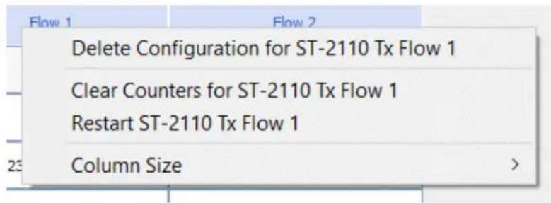
- Select Delete Configuration for ST-2110-30 Tx Flow.
A confirmation message appears.
IPedit

Disabling ST-2110 support for Channel 2 will end an active ST-2110 Rx subscription and will also will remove this channel from an active ST-2110 Tx flow.
Are you sure you want to proceed?

Clear the Statistics Counter for an existing Tx Flow
To clear the statistics for an existing Tx Flow, do the following:
- Right-click the flow for which you want to clear the statistics counter. A popup menu appears.

- Select Clear Counters for ST-2110-30 Tx Flow. The flow restarts.
Restart an Existing Rx Subscription
To restart an existing Rx Subscription, do the following:
- Right-click the subscription you want to restart. A popup menu appears.

- Select Restart ST-2110-30 Tx Flow. The flow restarts.
Delete an Existing Rx Subscription
To delete an existing Rx Subscription, do the following:
- Right-click the subscription you want to delete. A popup menu appears.
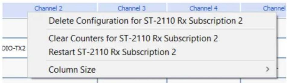
- Select Delete Configuration for ST-2110-30 Rx Subscription. A confirmation message appears.

Clear the Statistics Counter for an existing Rx Subscription
To clear the statistics for an existing Rx Subscription, do the following:
- Right-click the flow for which you want to clear the statistics counter. A popup menu appears.

- Select Clear Counters for ST-2110-30 Rx Subscription. The flow restarts.
Overview
Glitch-Free operation (also referred to as red/blue network operation) provides Ethernet link redundancy. This means there is a primary and secondary network communication link that can operate through a network failure. It is configurable in the intercom as well as in the keypanel. Failover is automatic and instantaneous.
IMPORTANT: Glitch-Free operation is not a licensed feature. It is available on ODIN hardware manufactured with an assignment of a MAC address for the secondary control interface (units built after April 22nd, 2020).
For a nominal flat fee, you can send your pre-April 2020 ODIN hardware to Warranty & After Sales Service for an upgrade that assigns the additional MAC address to make it hardware-ready for Glitch-Free operation.
Minimum Software Versions
• ODIN v1.7.0 or later
- KP-Series v2.6.0 or later
• AZedit v5.8.0 or later
• IPedit v3.8.0 or later
Features
- Two communication paths allows the intercom to operate through network failure due to secondary link is always waiting in the background.
- Intercom and keypanels have secondary IP address, MAC address, and Ethernet Interface.
• Audio and Control have link redundancy - Supports keypanel protocol, OMNEO audio routing commands, OMNEO audio transport, Offer protocol (connection handshake) and mDNS.
Install Glitch-Free Devices
The ODIN system supports 128 audio flows in and 128 audio flows out. Glitch-Free and non-Glitch-Free devices can coincide on the same system, but cannot go above the 128 audio flow limit.
Considerations
• ODIN supports up to 128 ports of full glitch-free devices.
• ODIN does not use 802.1Q VLAN tagging. Users must configure their networking equipment for port-based VLANs.
- Only keypanel audio and control protocols are supported on the secondary interface. The Firmware Upload Tool, IPedit, and DNS servers are only supported on the primary interface.
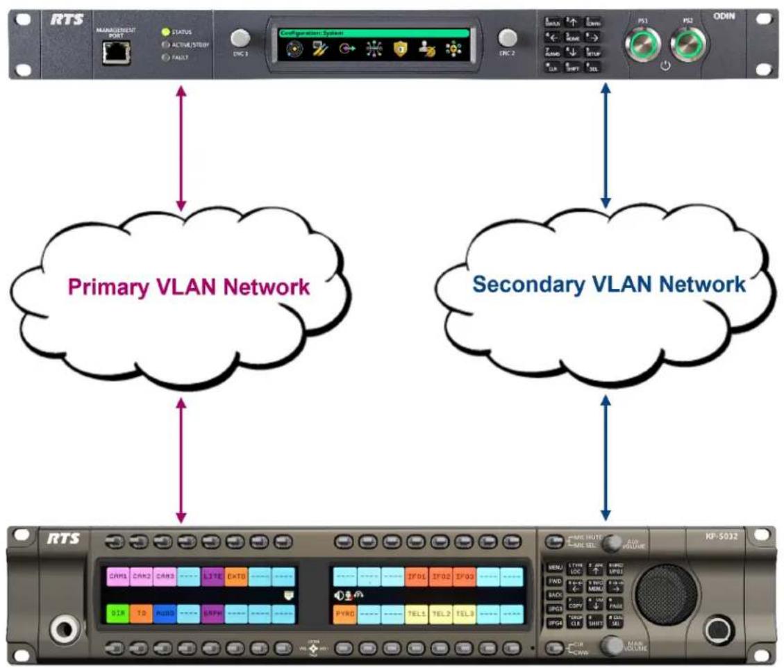
flowchart
graph TD
    A["RTS MANAGEMENT PORT"] --> B["STATUS ACTIVE/STUBY FAULT"]
    B --> C["Configuration System"]
    C --> D["PS1 PS2 ODIN"]
    E["Primary VLAN Network"] --> F["Secondary VLAN Network"]
    G["RTS"] --> H["ADA INPUT"]
    H --> I["ADA SELECT"]
    I --> J["ADA OUTPUT"]
    J --> K["ADA VOLUME"]
    style A fill:#f9f,stroke:#333
    style E fill:#bbf,stroke:#333
    style G fill:#bfb,stroke:#333
FIGURE 96. Glitch-Free System Diagram
To install ODIN with Glitch-Free over Ethernet, do the following:
- On the rear panel of ODIN, connect one end of an Ethernet (RJ-45) cable to the Primary VLAN Network.
- Connect the other end of the Ethernet (RJ-45) cable to J10 OMNEO PRI connector.
- Using a second Ethernet (RJ-45) cable, connect one end to the Secondary VLAN Network.
- Connect the other end of the second Ethernet (RJ-45) cable to the J10 OMNEO SEC connector.
NOTE: When Glitch-Free is enabled, RSTP is not supported.
To install ODIN with Glitch-Free over Fiber, do the following:
- On the rear panel of ODIN, connect one end of an SFP Fiber module to the Primary VLAN Network.
- Connect the other end of the Fiber cable to J11 OMNEO PRI (SFP) connector.
- Using a second Fiber cable, connect one end to the Secondary VLAN Network.
- Connect the other end of the second Fiber cable to J11 OMNEO SEC (SFP) connector.
To install KP-Series with Glitch-Free, do the following:
NOTE: The KP-Series panels have two PRI (primary) connectors – Ethernet and Fiber, and one SEC (secondary) connector – Ethernet only. You can use the Ethernet and Fiber primary connectors can used interchangeably, but you can only use one PRI connection with one SEC connection at a time.
- On the rear panel of KP Series keypanel, connect one end of an Ethernet (RJ-45) cable to the Primary VLAN Network.
- Connect the other end of the Ethernet (RJ-45) cable to J11 (PRI) OMNEO connector.
- Using a second Ethernet (RJ-45) cable, connect one end to the Secondary VLAN Network.
- Connect the other end of the second Ethernet (RJ-45) cable to the J12 (SEC) OMNEO connector.

FIGURE 97. Primary and Secondary OMNEO connector positions
Configure Glitch-Free Devices
With Glitch-Free operation you now have to configure a new secondary interface. There are three addressing schemes that can be used to set up the system:
• Zero-Configuration (Link Local) - requires no addressing
• Static Addressing - requires manual addressing
- DHCP (also known as dynamic addressing) - requires configuring the DHCP server if you do not already have a DHCP Server on your network. If using a third party DHCP Server, it must handout parameters compatible with OMNEO devices.
ODIN Glitch-Free Configuration
To configure ODIN from AZedit, do the following:
- From the Options menu, select Ethernet Configuration. The Ethernet Configuration screen opens.
- Click the OMNEO tab. The OMNEO page appears.
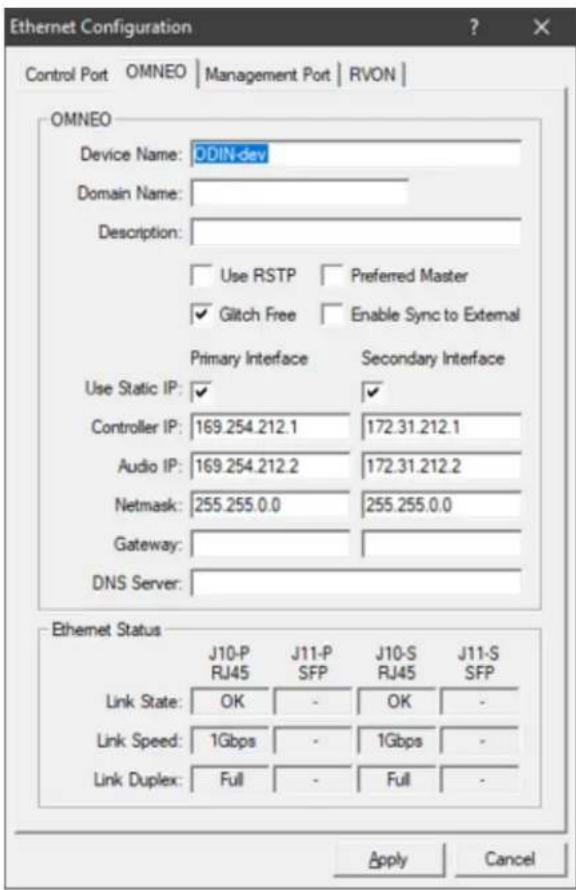
- Enter the Device Name of the ODIN device.
- Enter the Domain Name where ODIN is located.
- Select the Glitch Free check box.
NOTE: If you use DHCP or Link Local addressing, steps 7 through 10 can be skipped.
- Select the Use Static IP Settings check box.
- Enter the IP address assigned to the Primary and Secondary Interface Controller IP.
- Enter the IP address assigned to the Primary and Secondary Interface Audio IP.
- Enter the IP address assigned to the Secondary Interface Netmask.
- Click Apply.
To configure ODIN Glitch-Free operation from IPedit, do the following:
- From the Device Catalog, select the desired ODIN.
In the Device Configuration Panel - (Optional) Enter a description for ODIN.
- Select the Glitch Free check box.
NOTE: If the ODIN does not support Glitch-Free operation, a popup notification appears.

- Enter the IP address for the Primary and Secondary Interface Controller IP.
- Enter the IP address for the Primary and Secondary Interface Audio IP.
- Enter the IP address for the Netmask for both the Primary and Secondary Interfaces.

To check the Glitch-Free link status in IPedit, use the Channel Configuration panel. There are three statuses that may display: Both Links Up, Secondary Link Down, and Primary Link Down.
| OMNEO | Channels 1-16 | Channels 17-32 | Channels 33-48 | Channels 49-64 | Ch |
| Channel 21 | Channel 22 | Channel 23 | |||
| Channel Configuration | |||||
| Intercom Alpha | ODIN : N021 | ODIN : N022 | ODIN : N023 | ||
| Channel Description | |||||
| Destination Type | OKP-2 | OKP-2 | OKP-2 | ||
| Destination Device Name | DIRECTOR | TALENT 1 | TALENT 2 | ||
| Destination IP Address | 169.254.216.219 | 169.254.216.225 | 169.254.220.72 | ||
| Destination Description | |||||
| Destination Channel | Channel 1 | Channel 1 | Channel 1 | ||
| Destination Channel Description | |||||
| Channel Input Gain | 0 dB | 0 dB | 0 dB | ||
| Channel Output Gain | 0 dB | 0 dB | 0 dB | ||
| Receiver Latency | 1 ms | 1 ms | 1 ms | ||
| Channel Status | |||||
| Connection State | Connected | Connected | Connected | ||
| Connection Duration | 00:04:35 | 00:04:35 | 00:04:35 | ||
| Connection Drops | - | - | - | ||
| Glitch Free Status | Both Links Up | Secondary Link Down | Primary Link Down | ||
KP Series Glitch-Free Configuration
To configure KP-Series Glitch-Free operation using IPedit, do the following:
- From the Device Catalog, select the desired OKP.
In the Device Configuration Panel - (Optional) Enter a description for OKP.
- Select the Glitch-Free check box.
NOTE: If the KP-Series does not support Glitch-Free operation, a popup notification appears.

- Enter the IP address for the Primary and Secondary Interface Controller IP.
- Enter the IP address for the Primary and Secondary Interface Audio IP.
- Enter the IP address for the Netmask for both the Primary and Secondary Interfaces.

To check the Glitch-Free link status in IPedit, use the Channel Configuration panel. There are three statuses that may display: Both Links Up, Secondary Link Down, and Primary Link Down.
To enable DHCP on the Primary and Secondary connections from the front panel, do the following:
- Starting at the Service|OMNEO Setup menu, select OKP.
NOTE: OKP refers to the OMNEO keypanel using the OMNEO connection; however, if an OEI-2 is also attached to the AIO port, you see both OKP and OEI-2 options for selection.
- Press the SEL button.
Device Name, DHCP, and IP Parameters appear in the panel display.
-
Using the arrow buttons, select DHCP.
-
Press the SEL button.
Primary and Secondary appear in the panel display.
-
Using the arrow buttons, select Primary.
-
Press the SEL button.
Disabled and Enabled appear in the panel display.
-
Using the arrow buttons, select Enabled.
-
Press the SEL button.
-
Press the CLR button to exit the menu.
-
Repeat these steps to enable the secondary interface.
To configure Glitch-Free operation from the front panel with a static IP address, do the following:
-
Starting at the Service|OMNEO Setup menu, select OKP.
-
Press the SEL button.
Device Name, DHCP, and IP Parameters appear in the panel display.
-
Using the arrow buttons, select DHCP.
-
Press the SEL button.
Primary and Secondary appear in the panel display.
-
Using the arrow buttons, select Primary.
-
Press the SEL button.
Disabled and Enabled appear in the panel display.
- Verify DHCP is disabled.
NOTE: When making changes to the OKP IP parameters, DHCP must be disabled before changing the Domain name or IP Address. If DHCP is enabled, you can still view the IP Parameters, but you cannot make changes to them.
-
Press BACK.
-
Using the arrow buttons, select IP Parameters.
NOTE: SEL/FWD moves to the next octet, unless already on the last octet, in which case it save the current IP Address. CLR/BACK moves to the previous octet, unless already on the first octet, in which case it cancels editing of the IP Address.
- Press the SEL button.
IP Address, Gateway, Netmask, DNS Server, and Domain appear in the panel display.
-
Using the arrow buttons, select IP Address.
-
Press the SEL button.
Primary and Secondary appear in the panel display.
-
Using the arrow buttons, select Primary.
-
Press the SEL button.
The IP Address appears with the first octet blinking in the panel display.
-
Using the number pad, enter the first octet number in the IP Address.
-
Press the SEL button.
The focus shifts to the second octet.
-
Using the number pad, enter the second octet number in the IP Address.
-
Press the SEL button.
The focus shifts to the third octet.
-
Using the number pad, enter the third octet number in the IP Address.
-
Press the SEL button.
The focus shifts to the last octet.
-
Using the number pad, enter the last octet number in the IP Address.
-
Press the SEL button.
The OKP Setup menu options appear in the panel display.
- Repeat these steps for the Secondary IP Address.
To configure the Gateway Address, do the following:
- Using the arrow buttons, select Gateway.
Primary and Secondary appear in the panel display.
-
Using the arrow buttons, select Primary.
-
Press the SEL button.
The Gateway Address appears with the first octet blinking in the panel display.
-
Using the number pad, enter the first octet number in the Gateway Address.
-
Press the SEL button.
The focus shifts to the second octet.
-
Using the number pad, enter the second octet number in the Gateway Address.
-
Press the SEL button.
The focus shifts to the third octet.
-
Using the number pad, enter the third octet number in the Gateway Address.
-
Press the SEL button.
The focus shifts to the last octet.
-
Using the number pad, enter the last octet number in the Gateway Address.
-
Press the SEL button.
The OKP Setup menu options appear in the panel display.
- Repeat these steps for the secondary Gateway Address
To configure the Netmask Address, do the following:
- Using the arrow buttons, select Netmask.
Primary and Secondary appear in the panel display.
-
Using the arrow buttons, select Primary.
-
Press the SEL button.
The Netmask Address appears with the first octet blinking in the panel display.
-
Using the number pad, enter the first octet number in the Netmask Address.
-
Press the SEL button.
The focus shifts to the second octet.
-
Using the number pad, enter the second octet number in the Netmask Address.
-
Press the SEL button.
The focus shifts to the third octet.
-
Using the number pad, enter the third octet number in the Netmask Address.
-
Press the SEL button.
The focus shifts to the last octet.
-
Using the number pad, enter the last octet number in the Netmask Address.
-
Press the SEL button.
The OKP Setup menu options appear in the panel display.
- Repeat these steps for the secondary Netmask Address.
Bosch Security Systems, LLC
12000 Portland Avenue South
Burnsville, MN 55337 U.S.A.
www.rtsintercoms.com
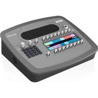
- PROPRIETARY NOTICE
- COPYRIGHT NOTICE
- WARRANTY AND SERVICE INFORMATION
- CUSTOMER SUPPORT
- TECHNICAL QUESTIONS
- DISCLAIMER
- Important Safety Instructions
- Table
- of
- Contents
- INTRODUCTION 13
- INSTALLATION 21
- BASIC OPERATION 37
- KP Series
- FIRMWARE DOWNLOAD 161
- KP-4016/5032 MENU SYSTEM 185
- TELEPHONE INTERFACE (TIF) OPERATION 259
- KEYPAD QUICK REFERENCE 265
- KEYPANEL MENU QUICK REFERENCE 269
- EKP-4016 287
- Unicode Support 293
- Power Supply Mounting Options 297
- Audio and Control Packages 303
- ST-2110-30 for RTS OMNEO Devices 307
- Glitch-Free Operation - ST2022-7 317
- List
- Figures
- KP Series 11
- Features
- Specifications
- LCD Display
- KP-4016:
- KP-5032
- Power Supply:
- General Purpose Inputs and Outputs:
- Outputs
- Inputs
- Inputs:
- Matrix
- Aux 1 and Aux 2
- Front Panel Mic
- Rear Panel Mic
- Front and Rear Headset Mic - Electret
- Front and Rear Headset Mic - Dynamic
- Outputs:
- MIC/LINE Out
- Headset - Front, Rear
- Speaker - Rear
- Speaker - Front
- Digital:
- OMNEO Channels
- Environmental:
- Dimensions
- KP-4016
- Weight
- Temperature
- Power Consumption:
- Certification:
- CE Compliance
- EMC
- Safety
- KP-4016/5032 Block Diagram
- Reference View - KP-5032
- Reference View - KP-4016
- Requirements
- KP-5032/5032PB Installation
- IMPORTANT:
- NOTE:
- KP-4016/4016PB Installation
- Connecting the Keypanel to the Intercom
- Naming Devices in IPedit
- Naming the OMI in AZedit
- Configure the OMI using AZedit
- Add the OMI to the Device Catalog in IPedit
- Configure the OMI using IPedit
- Add the KP-Series Keypanels to the Device Catalog in IPedit
- Configure the KP-Series Panels using IPedit
- Connecting the KP-Series Panels through the OMNEO Offers Menu
- Power Up
- Address Setting
- General Information
- Connections
- Frame Connector
- Ethernet Connector
- Panel Microphone Connector
- Headset Connector
- Female Headset Connector
- Male Headset Connector
- Changing the Front Headset Connector
- GPIO 12-Position Terminal Block Connector
- Wire Specifications
- Speaker 2-Position Terminal Block Connector
- Footswitch Cabling
- Intercom Keys and Displays
- Color Display Descriptions for Intercom Keys
- Display Icons
- Keypad Reference View
- Primary Mode
- Dial Mode
- SHIFT Mode
- DIAL
- INFO button
- Breadcrumb Menu Navigation
- Menu Navigation and Shaft Encoder Knobs
- CLR Button
- Basic Key Operation
- Lever Key
- Pushbutton
- OR
- Talk/Listen Indicator
- Key Gain Adjustment
- Keypanel Volume Adjustments
- Aux Volume Adjustments
- Priority Call Volume Control
- Operation of Intercom Keys with Auto Functions
- Operation of Intercom Keys with Options
- Group Option Keys
- Solo Key
- Exclusive Key
- Lock Key
- Chime Key
- Clear Keys
- Latching Keys
- Operation of Intercom Talk Keys with the Speaker DIM Setting
- Operation of Intercom Keys assigned to TIF Ports
- User Quick Select Scrolling
- Graphical Call Waiting Window
- Graphical Call Waiting Window Operation
- Display or Hide the CWW
- Incoming Calls
- Clearing the CWW List
- Mute the Microphone
- Mic Select
- Setup Pages
- Menu Passwords
- Voice Messaging (Audio Package Only)
- Voice Messages Menu
- VM Playback Menu
- Alpha Length
- User Programmable Buttons
- Keypanel Color Window
- Function Types Page
- Select Intercom Drop Down Menu
- Recent Colors Group Box
- Current Color Group Box
- Apply To Background Button
- Default Background Button
- Apply To Text Button
- Default Text Button
- Color Grid
- Function Type Column
- Color Column
- Only Show Non-Default Background Colors Check Box
- Key Assignment Page
- Select Function Type Drop Down Menu
- Function Number Column
- Assignment Groups Page
- Select Assignment Group Drop Down Menu
- Intercom Column
- Miscellaneous Colors Page
- Enhanced Tallies
- Tally # Column
- Mode Column
- Description Column
- Duration Column
- Characteristics Column
- Chime # Column
- Legacy Action Column
- Flash Text Characteristics Window
- Swap Foreground / Background Colors Check Box
- Flash State Group Box
- Set Text Color Check Box
- Selected Color Cell and Ellipsis Button
- Set Background Color Check Box
- Normal State Group Box
- Set Alternate Text Check Box and Entry Field
- Duty Cycle Drop Down Menu
- OK Button
- Cancel Button
- Show Icon Characteristics Window
- Icon Drop Down Menu
- Enhanced Tally Icons
- Panel Tally
- Suggested Use Suggested Use
- Create and Download New Icons
- Key Overlay Icons
- Panel Icons
- Keypanel Mirroring (Control Package Only)
- Real-Time Control in AZedit (Control Package Only)
- Intercom Volume Controls
- Keypanel Volume Controls
- Mic Mute
- Headset Transfer
- AFK Mode
- Enable Tone
- Keypanel Configuration (Control Package Only)
- Upload a Configuration File from a Keypanel
- Load Button
- Save All Button
- Save Changes Button
- Apply Button
- LCP Encoder Assignments Group Box
- Panel Swap Group Box
- UPG Key Definition Group Box
- Quick-Assign Listen Assignments Group Box
- Panel Mode Group Box
- Miscellaneous Group Box
- Snoop Tally Group Box
- GPI Inputs Assignments Group Box
- GPI Output Assignments Group Box
- Footswitch Mode Group Box
- Display Page
- Keypad Backlight Group Box
- Key Display Options Group Box
- Panel Display Options Group Box
- LCD Backlight Group Box
- Screen Saver Group Box
- Key Options Page
- Solo And Exclusive Keys Group Box
- Latch Disable Group Box
- Button Lock Group Box
- Tallies Group Box
- Autodial Numbers Group Box
- One-Touch Autodials Group Box
- Key Groups Group Box
- Chimes Group Box
- Key Icons Group Box
- Key Volumes Group Box
- Audio Options Page
- Mic Modes Group Box
- Speaker / Headset Modes Group Box
- Aux Inputs Group Box
- Input Display Column
- Mode Drop Down Menu Column
- Number of Analog Aux Inputs Drop Down Menu
- Mic Options Group Box
- Matrix Out and Sidetone Options Group Box
- Headset Configuration Group Box
- Ganged Volume Group Box
- Tone Generator Group Box
- VM Options Group Box
- Audio Levels Page
- Input Volumes Group Box
- Output Volumes Group Box
- Minimum Output Volumes Group Box
- Output Dim Amounts Group Box
- Minimum Input Volumes Group Box
- Maximum Output Volumes Group Box
- Chime Volumes Group Box
- Advanced Page
- AGC Group Box
- Mixing Group Box
- Compression Group Box
- Gating Group Box
- Noise Gate Group Box
- Filters Page
- Input Bandpass Filters Group Box
- Output Bandpass Filters Group Box
- Input Equalization Filters Group Box
- Output Equalization Filters Group Box
- Notch Filter Mode
- Download Firmware to the Keypanel From AZedit
- REPROGRAMMING DO NOT POWER OFF
- From the File menu, select Options.
- Click the Change button.
- Click the Upload button.
- Enable Downloading New Bootloader from the Keypanel
- Download Firmware Using the Bootloader
- Run the Bootloader
- Click Open.
- Click Begin Download.
- Click OK.
- Display the FPGA Version on the Keypanel
- Download and Upgrade the FPGA to the KP-5032/4016
- Click Open.
- Click Begin Download.
- Click OK.
- Download a Splash Screen
- Download a Font File
- Download an Icon File
- Download User Chimes (Control Package Only)
- Click Begin Download.
- Download Screen Savers (Control Package Only)
- Main Menu Access
- Menu System, Audio Options
- Audio Options Menu, Advanced
- AEC
- Mic Priority
- AGC
- Attack
- Decay
- Compression
- Filters
- Bandpass
- Equalization
- Adjustable 5-Band Equalization - Audio Package Only
- Notch
- Gating
- Metering
- Mixing
- Mix Mode
- Noise Gate
- Noise Gate - Audio Package Only
- Audio Options Menu, Chime
- Audio Options Menu, Dim
- Audio Options Menu, Ganged Vols
- Audio Options Menu, Headset Mic
- Auto-Mute
- Mode
- Type
- Audio Options Menu, Headset Speaker
- Volume Control
- Auto-Transfer
- Audio Options Menu, Inputs
- Audio Options Menu, Key Volumes
- Minimum
- Audio Options, Menu, LCP 16 CLD
- Audio Options Menu, Matrix Out
- Audio Options Menu, Max Volume
- Audio Options Menu, Mic Gain
- Audio Options Menu, Mic Mute
- Audio Options Menu, Min Volume
- Audio Options Menu, Output Level
- Audio Options Menu, Panel Mic
- Audio Options Menu, Preamp Out
- Audio Options Menu, Sidetone
- Audio Options Menu, Speaker
- Audio Options Menu, Tone Gen
- Audio Options Menu, VM Options (Audio Package Only)
- Playback Menu
- Recording Menu
- Auto Recording
- When Mailbox Full
- Menu System, Display
- Display Menu, Assign Type
- Display Menu, Auto Dial
- Display Menu, Chans On
- Display Menu, Chime
- Display Menu, Exclusive
- Display Menu, Key Groups
- Display Menu, Key List
- Display Menu, LCP 16 CLD
- Display Menu, Level 2
- Display Menu, Listen
- Display Menu, MAC Address
- Display Menu, Matrix
- Display Menu, Panel ID
- Display Menu, Solo
- Display Menu, Version
- Menu System, Key Assign Menu
- Key Assign Menu, Matrix (Trunked System Only)
- Key Assign Menu, Pt-to-Pt
- Key Assign Menu, Party Line
- Key Assign Menu, IFB
- Key Assign Menu, Special List
- Key Assign Menu, Sys Relay
- Key Assign Menu, Camera ISO
- Key Assign Menu, UPL Resources
- Key Assign Menu, IFB Spcl List
- Key Assign Menu, Auto Funcs
- Menu System, Key Options Menu
- Key Options Menu, Auto Dial
- 01: appears in the panel display.
- 01: with a blinking cursor appears in the panel display.
- 01: with a flashing cursor appears.
- 01: appears in the panel display. The auto dial number is erased.
- Key Options Menu, Chime
- Key Options Menu, Clear
- Key Options Menu, Exclusive
- Key Options Menu, Icons
- Key Options Menu, Key Groups
- Key Options Menu, Latching
- Key Options Menu, Lock (Button Lock)
- Key Options Menu, Panel Swap
- Panel Swap Control Options
- Navigation Mode for Panel Swap
- Panel Swap Key States
- Key Options Menu, Solo
- Key Options Menu, Tallies
- Key Options Menu, Turn Off
- Menu System, OMNEO Offers
- OMNEO Matrix Connection Configuration
- OMNEO Aux Port Configuration
- RVON-IO Matrix Connection
- Menu System, Save Config
- Menu System, Service
- Service Menu, Alphas
- Service Menu, Aux Select
- Service Menu, CWW
- Number of Entries
- On New Caller
- Service Menu, Display
- Menu Context
- Show Volume
- KP32 Emulation
- Service Menu, Footswitch
- Enabling
- Disabling
- Latch Operation
- Service Menu, Intercom Mode
- Service Menu, Key View
- Service Menu, Keypad
- Backlight
- Setup
- Activation
- SEL Key
- Service Menu, LCD Backlight
- Service Menu, Local GPIO
- Service Menu, Mirror (Control Package Only)
- Service Menu, OMNEO Setup
- Service Menu, Page Change
- Service Menu, Reset Cfg
- Service Menu, RVON Setup
- Service Menu, Scrn Saver
- Service Menu, Set Address
- Service Menu, Snoop Tally
- Service Menu, Test Panel
- Telephone Interface (TIF) Operation
- Receiving A Phone Call
- Dialing and Hanging Up
- Manual Dial
- Keypanel Hang Up
- Auto Dial
- Centralized Auto Dials
- Centralized Auto Dial
- Keypad Sequence Introduction
- Keypad Sequences
- Keypanel Menu Quick Reference
- KP Series Keypanel Menu Quick Reference 281
- Introduction
- EKP-4016 Expansion Panel
- Reference View
- Expansion Panel Cabling Reference
- AZedit and Unicode Support
- Power Supply Mounting Options
- Power Supply Mounting Bracket Instructions
- Mounting the Power Supply to KP-5032/5032PB Unit
- Mounting the Power Supply to EKP-4016/4016PB Unit
- EKP-4016 Rear Panel View
- Mounting the Power Supply to a Standard Rack
- Audio and Control Add-On Package
- Download License Files
- Prerequisites
- Operation
- Set Device Parameters
- Setting up a ST-2110-30 Tx (Transmit) Audio Stream
- UNDER FLOW CONFIGURATION
- UNDER FLOW STATUS
- Set up a ST-2110-30 Transmit (Rx) Audio Flow
- Select the ST-2110-30 Rx tab.
- Click the Browse button in the Session Name field.
- Select a ST-2110-30 Tx flow from the left-hand window.
- Click OK.
- Send the changes to the matrix.
- IPedit Operations
- Restart an Existing Tx Flow
- Delete an Existing Tx Flow
- Clear the Statistics Counter for an existing Tx Flow
- Restart an Existing Rx Subscription
- Delete an Existing Rx Subscription
- Clear the Statistics Counter for an existing Rx Subscription
- Overview
- Minimum Software Versions
- Install Glitch-Free Devices
- Considerations
- Configure Glitch-Free Devices
- ODIN Glitch-Free Configuration
- KP Series Glitch-Free Configuration
- Bosch Security Systems, LLC
Brand : RTS
Model : KP-5032
Category : Audio mixer