Master MiniPro - Laptop Positivo - Free user manual and instructions
Find the device manual for free Master MiniPro Positivo in PDF.


| Product Type | Notebook / Laptop |
| Brand | Positivo |
| Model | Master MiniPro |
| Storage | Hard Disk Drive (HDD), user-replaceable |
| Memory | RAM memory, user-removable (DDR3L or DDR4) |
| Processor | Intel Celeron or similar (not confirmed) |
| Display Size | 14 inches (typical, not specified) |
| Battery | Removable, user-replaceable |
| Power Supply | External AC adapter, 100-240V input |
| Operating System | Windows 10 (assumed) |
| Connectivity | USB 2.0/3.0, HDMI, audio jack (typical) |
| Main Functions | General computing, internet, office applications |
| Care and Cleaning | Use a soft dry cloth to clean the exterior; do not use liquids |
| Safety Precautions | Unplug before cleaning; avoid exposure to liquids |
| Spare Parts Availability | Internal components (HDD, RAM, fan, battery, motherboard) are replaceable; contact Positivo support |
| Repairability | User-serviceable with basic tools (Torx and slotted screwdrivers, pliers) |
| General Information | Designed by Positivo; includes end-of-life disassembly instructions for recycling |
Frequently Asked Questions - Master MiniPro Positivo
User questions about Master MiniPro Positivo
0 question about this device. Answer the ones you know or ask your own.
Ask a new question about this device
Download the instructions for your Laptop in PDF format for free! Find your manual Master MiniPro - Positivo and take your electronic device back in hand. On this page are published all the documents necessary for the use of your device. Master MiniPro by Positivo.
USER MANUAL Master MiniPro Positivo
4.3.1.1 Identification of materials and components requiring selective treatment
Product Identification:
| Family | Product Model |
| Positivo MiniPro | C6200, C8200, C4300, C4400, C6400, C8400, C5300,C6300 AND C8300 |
Product Disassembly instructions for End of Life
Purpose: The document is intended for use by end-of-life recyclers or treatment facilities. It provides the basic instructions for the disassembly of products to remove components and materials requiring selective treatment.
1. Tools Required
List the type and size of the tools that would typically be used to disassemble the product to a point where components and materials requiring selective treatment can be removed.
| Tool Description |
| Torx and Slotter Screw Driver |
| Gloves |
| Pliers |
2. Product disassembly Process
2.1 List the basic steps that should typically be followed to remove components and materials requiring selective treatment:
2.1.1 Remove top over > Remove Front Bezel > Remove HD > Remove HDD from Cage > Disconnect Sata Cable > Remove Fan and Fan Cable > Remove CPU and Battery > Remove memory > Remove motherboard from top cover. Take off AC Adapter Power Cord> Open AC Adapter case > Remove PCB Covers > Cut Cables > Remove Capacitor
2.1.2 List of PCBs to be removed
- Mainboard
- Memories
- HDD
-
Ac Adapter board
-
Related regulations: WEEE directive, EPEAT
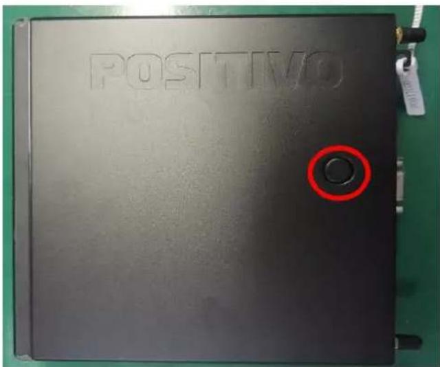
Step 1 – Press the button and pull of the top cover

natural_image
Two black plastic electronic devices with hexagonal patterns, one partially open and the other closed, held by gloved hands (no visible text or symbols)Step 2 – Remove Front Bezel

Step 3 – With Torx Screw, Loose and remove screws, remove HD

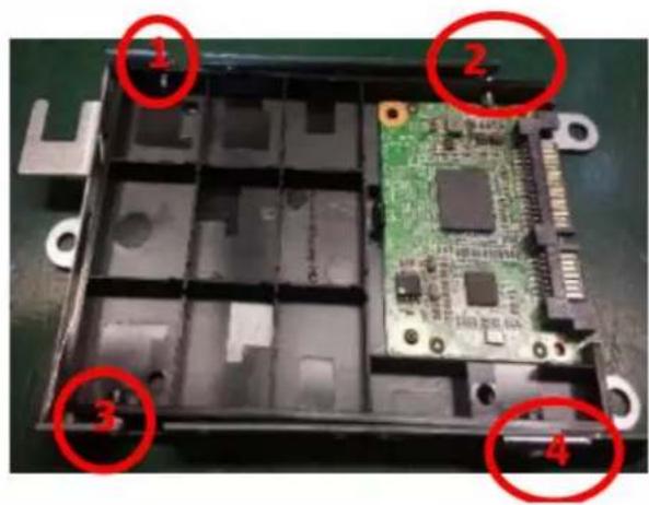
Step 5 – With Torx Screw, Loose Screws from the HDD support. Pull off HDD from cage.
natural_image
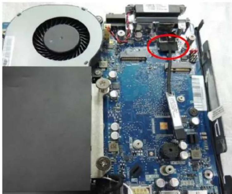
Close-up of an open computer motherboard with a fan, heatsink, and electronic components (no visible text or symbols)Step 6 - Disconnect SATA Cable from motherboard
natural_image
Close-up of a computer motherboard showing a fan blade and heatsink, with numbered annotations (1, 2, 3) highlighting specific components.
natural_image
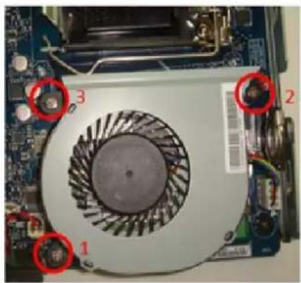
Interior view of an open computer motherboard with a highlighted component (no visible text or symbols)Step 7 – With Torx Screw Loose Screws and take the fan off. Disconnect Fan cable from PLM.

natural_image
Close-up of gloved hands assembling a blue circuit board with a black plastic component (no visible text or symbols)Step 8 – Rotate the CPU lever and pull it off, with Slotted Screw Driver pull of the battery

natural_image
Close-up of a computer motherboard with visible CPU socket, RAM slots, and a highlighted slot (no readable text or symbols)Step 09 – Remove Memories
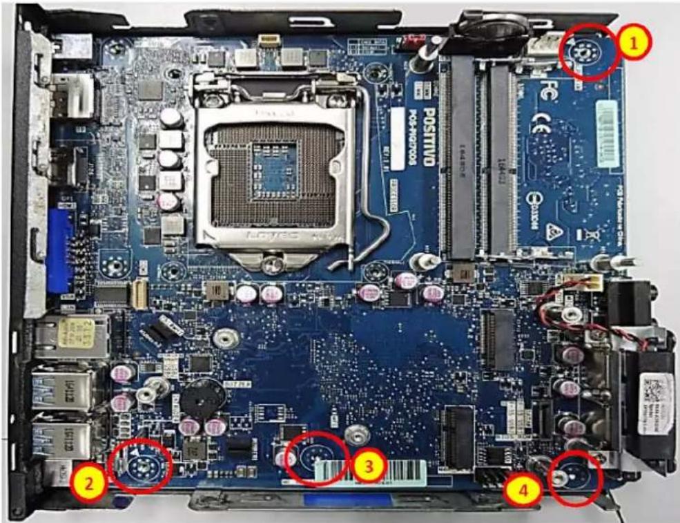
Step 10 - With Torx Screw Loose Screws and pull MB off the bottom cover.
natural_image
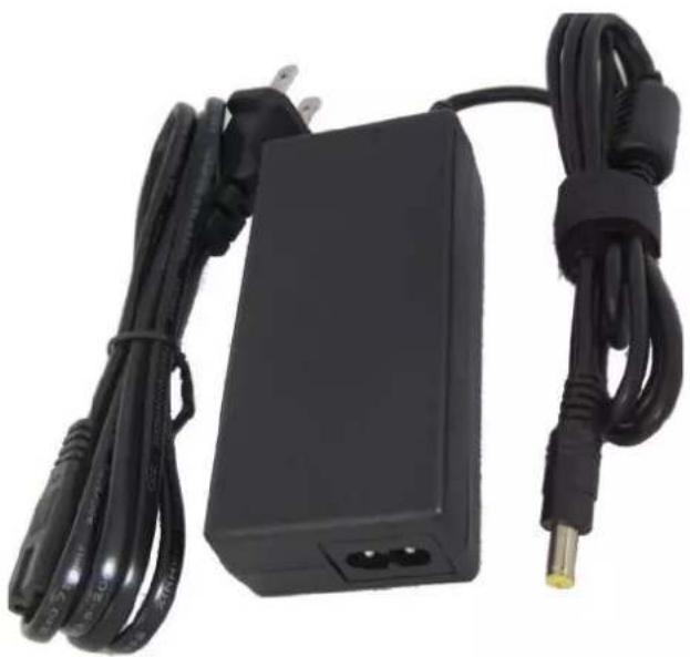
Black rectangular electronic device with attached cable and power connector (no visible text or symbols)Step 11 – Separate the AC Power Cord

natural_image
Close-up of a black electronic device with coiled wires attached, no visible text or symbolsStep 11 – With slotted screw driver open the AC Adapter
natural_image
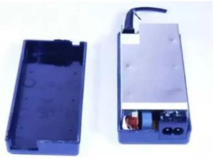
Two views of an open blue battery casing, one open and one closed, showing internal components (no text or symbols visible)Step 12 – Pull up the PCB Cover

natural_image
Close-up of a device's internal components showing a plug inserted into a circuit board, with a magnified view of the cable being attached (no text or symbols visible)Step 13 – With a plier cut the cable and socket out.

natural_image
Close-up of hands holding an open electronic device with internal components, no visible text or symbolsStep 14 – Remove Electrolytic Capacitor and circuit board
Brand : Positivo
Model : Master MiniPro
Category : Laptop