22MP55VQ - Screen Positivo - Free user manual and instructions
Find the device manual for free 22MP55VQ Positivo in PDF.


| Product Type | 21.5-inch LED Monitor |
| Model Number | 22MP55VQ |
| Brand | Positivo |
| Screen Size | 21.5 inches (diagonal) |
| Panel Type | IPS (In-Plane Switching) |
| Resolution | 1920 x 1080 (Full HD) |
| Aspect Ratio | 16:9 |
| Refresh Rate | 60 Hz |
| Response Time | 5 ms (GTG) |
| Brightness | 250 cd/m² |
| Contrast Ratio | 1000:1 (Static) |
| Viewing Angle | 178° / 178° |
| Input Connectors | 1 x HDMI, 1 x D-Sub (VGA), 1 x DP |
| Power Consumption | Typical: 25 W, Standby: <0.5 W |
| Power Supply | Internal, 100-240 V AC, 50/60 Hz |
| VESA Mount | 100 x 100 mm |
| Stand Features | Tilt only |
| Dimensions (with Stand) | Approx. 508 x 386 x 188 mm |
| Weight (with Stand) | Approx. 4.5 kg |
| Cleaning Instructions | Use soft dry cloth; do not use alcohol or abrasive cleaners. |
| Safety | Do not disassemble when plugged in; avoid moisture and heat sources. |
| Repairability | Disassembly requires Phillips and hexagonal N5 screwdrivers, plastic ZIG tool, and gloves. Key components: LCD panel, power board, main board. |
| Included Accessories | Power cable, D-Sub cable, HDMI cable, DP cable, user manual |
Frequently Asked Questions - 22MP55VQ Positivo
User questions about 22MP55VQ Positivo
0 question about this device. Answer the ones you know or ask your own.
Ask a new question about this device
Download the instructions for your Screen in PDF format for free! Find your manual 22MP55VQ - Positivo and take your electronic device back in hand. On this page are published all the documents necessary for the use of your device. 22MP55VQ by Positivo.
USER MANUAL 22MP55VQ Positivo
4.3.1.1 Identification of materials and components requiring selective treatment
Product Identification:
| Marketing Name / Model Description | |
| 22MP55VQ 21.5” |
Product Disassembly instructions for End of Life
Purpose: The document is intended for use by end-of-life recyclers or treatment facilities. It provides the basic instructions for the disassembly of products to remove components and materials requiring selective treatment.
1. Tools Required
List the type and size of the tools that would typically be used to disassemble the product to a point where components and materials requiring selective treatment can be removed.
| Tool Description |
| Screw driver Phillips and hexagonal N5 |
| Plastic ZIG |
| Gloves |
| Pliers |
2. Product disassembly Process
2.1 List the basic steps that should typically be followed to remove components and materials requiring selective treatment:
2.2 OPTIONAL: Depending upon the complexity of the disassembly process, a graphic depicting the locations of items contained within the product which require selective treatment (with descriptions and arrows identifying locations) can be inserted below:
2.3 How to write
1) Provide a picture of disassembly process
2) All the screws are showed in the picture
3) All the PCBAs are showed in the picture
4) LCD panel are showed in the picture
5) All the accessories like remote controller, batteries, and cables are showed in the picture
3. Related regulations: WEEE directive, EPEAT
Main Parts:


natural_image
Black LG computer monitor on a green table with plastic wrap, no visible text or symbols on the device itself.Step 1 - Put the MNT on the clean vinyl.

natural_image
Two views of a mechanical component with red arrows indicating process, showing internal structure and assembly (no text or symbols)Step 2 – Pull the Stand Body down and remove it from the Back Cover
POSITIVO
natural_image
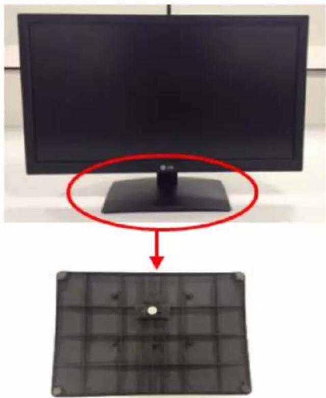
Two-panel image showing a monitor and a solar panel with a red circle highlighting the top portion of the monitor (no text or symbols present)Step 3 – Removing the Stand Base

natural_image
Two-panel photo showing hands installing or adjusting a black rectangular panel on a workbench, no visible text or symbols.Step 4 - Open cabinet from set

natural_image
Person in gloves installing or adjusting a black plastic tray on a workbench (no visible text or symbols)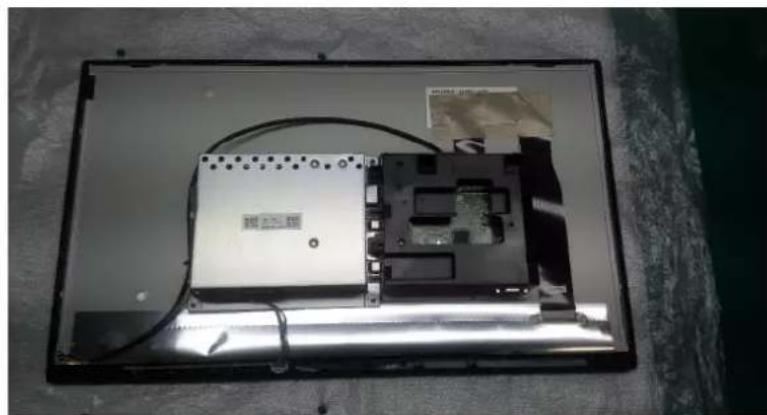
natural_image
Interior view of an electronic device casing with exposed circuit board and cable, no visible text or symbolsStep 5 – Open cabinet from set

natural_image
Close-up of a gloved hand installing or adjusting a damaged component on a computer monitor (no visible text or symbols)Step 6 – Remove all tapes

natural_image
Close-up of gloved hands holding a small electronic component (no visible text or symbols)
natural_image
Close-up of gloved hands installing a cable on a black electronic device with a small multimeter inserted (no visible text or symbols)POSITIVO

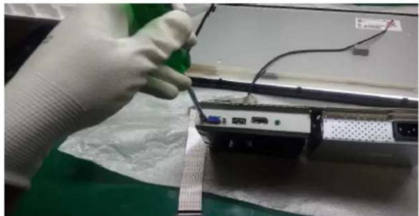
Step 7 - Unplug all cables.
POSITIVO
natural_image
Close-up of a gloved hand using a screwdriver to adjust cable or connector on a laptop (no visible text or symbols)
natural_image
Close-up of a gloved hand inserting electronic components into a green circuit board (no visible text or symbols)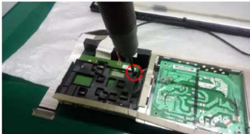
natural_image
Close-up of a soldering tool inspecting a green printed circuit board with a red circle highlighting a defect (no text or symbols visible)POSITIVO

natural_image
Close-up of a gloved hand installing or adjusting a black plastic electronic component into a green circuit board (no visible text or symbols)
natural_image
Close-up of a green printed circuit board being cut with a tool, no visible text or symbolsStep 8 - Remove all screws.

natural_image
Close-up of gloved hands holding a small electronic component on a black plastic panel (no visible text or symbols)Step 9 - Pull control board and remove from front cabinet
POSITIVO

natural_image
Close-up of hands installing a green printed circuit board into a plastic-wrapped device (no visible text or symbols)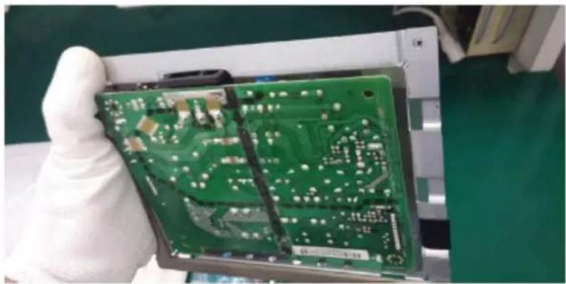
natural_image
Hand holding a green printed circuit board with visible traces and components (no text or symbols)Step 10 - Remove PCB Board in the metallic shield

natural_image
Person in gloves handling a device with a plastic cover (no visible text or symbols)POSITIVO

Step 11 - Remove all gaskets and separate metal part with plastic part
POSITIVO

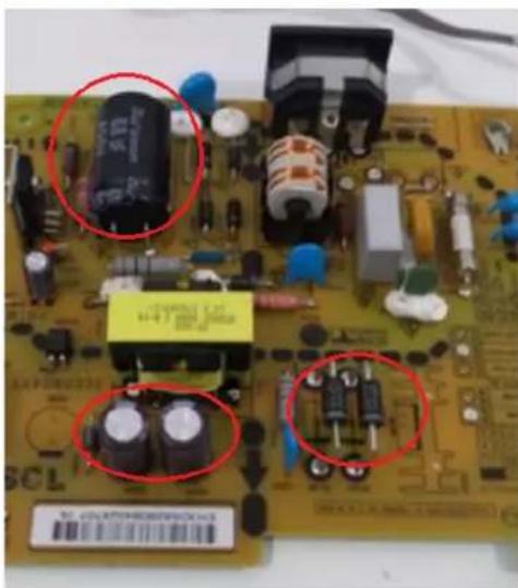
Step 12- At Power PCB using pliers cut the connection between capacitor and board. For the glued capacitors take if off pushing it.
natural_image
Close-up of a printed circuit board with electronic components and two red-circled annotations (no readable text or symbols)
Step 13 - All items disassembly Back Cover
- LCD Module
- Stand Body
- Stand Base
- Bracket
- PCB Bracket
- Cabinet
- LCD FRAME
- Energy Cables
- DP Cables
- D-SUB Cables
- HDMI CABLE
- Metal Av Shield
- PSU Shield
POSITIVO
- Main Board
- Power board and PSU
- Flat cable
- Gaskts (EMI)
- Gasket Sponge
- Cables
- Cables
- Cables
- Manual
Brand : Positivo
Model : 22MP55VQ
Category : Screen