
WGCL132 - Electrical switch HAGER - Free user manual and instructions
Find the device manual for free WGCL132 HAGER in PDF.


| Product Type | Modular Circuit Breaker |
| Brand | Hager |
| Model | WGCL132 |
| Rated Current | 32 A |
| Rated Voltage | 230/400 V AC |
| Frequency | 50/60 Hz |
| Number of Poles | 1P |
| Tripping Characteristic | C |
| Breaking Capacity | 6 kA |
| Dimensions (W x H x D) | 17.5 mm x 85 mm x 70 mm |
| Weight | 150 g |
| Mounting | DIN Rail EN 60715 |
| Protection Class | IP20 |
| Operating Temperature | -25°C to +40°C |
| Energy Limitation Class | 3 |
| Electrical Endurance | ≥ 10,000 cycles |
| Mechanical Endurance | ≥ 20,000 cycles |
| Connection Capacity | 1 to 25 mm² |
| Tightening Torque | 2.5 Nm |
| Maintenance | Clean with a dry cloth; no lubrication required |
| Spare Parts | None available; device must be replaced if faulty |
| Compliance | IEC/EN 60898-1 |
Frequently Asked Questions - WGCL132 HAGER
User questions about WGCL132 HAGER
0 question about this device. Answer the ones you know or ask your own.
Ask a new question about this device
Download the instructions for your Electrical switch in PDF format for free! Find your manual WGCL132 - HAGER and take your electronic device back in hand. On this page are published all the documents necessary for the use of your device. WGCL132 by HAGER.
USER MANUAL WGCL132 HAGER
16AX switches 1way/2way 10AX intermediate switch Hager Muse / Hager Inspire
Installation manual
Safety instructions
Electrical equipment must only be installed and assembled by a qualified electrician in accordance with the relevant installation standards, regulations, directives and safety and accident prevention directives of the country.
Failure to comply with these installation instructions may result in damage to the device, fire or other hazards.
Function
Mechanical light switches for electrical installations in buildings.
Correct use
- For the flush-mounted installation in standard wall boxes (recommended wall box depth ≥ 35 mm).
- Only suitable for use in indoor areas with no drip and no spray water.
Technical data
Rated voltage: 250 V\~
Frequency: 50/60 Hz
Conductor cross-section of screw terminals: max. 3 x 1.5 mm ^4
Distance of fixing holes: 60.3 mm
Switch compliance: BS EN 60669-1, IEC 60669-1
16AX switches 1way/2way
Rated current: max. 16 AX
10AX intermediate switch
Rated current: max. 10 AX
Information for electricians
Installation and electrical connection

DANGER!
Touching live parts can result in an electric shock.
An electric shock can lead to death.
Disconnect the connecting cables before working on the device and cover all live parts in the area!
Preparing the device for installation
(for example "16AX 2gang 1way switch")
1

- Carefully loosen the frame on the notches with a flat-blade screwdriver. Lift up and remove the frame (1).
■ Remove the rockers also with a flat-blade screwdriver.
Connecting the device
2A

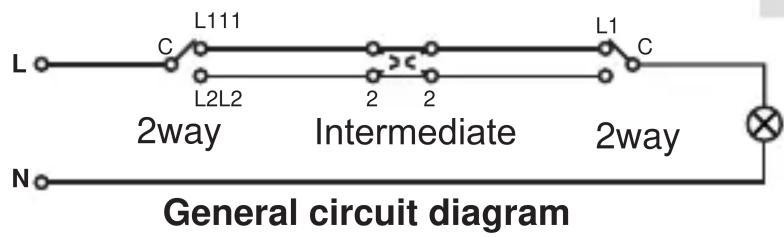
General circuit diagram

1gang 1way switch
1way switch
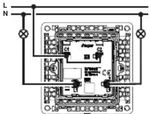
2gang 1way switch
2B

2way switch


2C
Intermediate switch

- Strip connection cables approx. 10 ... 12 mm.
■ Wire the switch according to the appropriate wiring diagram (2A or 2B or 2C).
Installing the device into the wall box
(for example "16AX 2gang 1way switch")
3

natural_image
Diagram of a cable or connector assembly with internal components and wiring, no visible text or symbols■ After wiring, fix the device with the two screws attached into the wall box (3).
Assembling the rockers and frame
(for example "16AX 2gang 1way switch")
4

■ Fix the rockers and frame onto the device (4).
2-5gang frames are available for multiple combinations.



- 16AX switches 1way/2way 10AX intermediate switch Hager Muse / Hager Inspire
- Safety instructions
- Function
- Correct use
- Technical data
- Information for electricians
- Installation and electrical connection
- Preparing the device for installation
- Connecting the device
- Installing the device into the wall box
- Assembling the rockers and frame
Brand : HAGER
Model : WGCL132
Category : Electrical switch