
TH1INB 60 - Cooker Thermex - Free user manual and instructions
Find the device manual for free TH1INB 60 Thermex in PDF.


| Product Type | Induction Cooker |
| Brand | Thermex |
| Model | TH1INB 60 |
| Number of Cooking Zones | 4 |
| Cooking Technology | Induction |
| Power Supply | 220-240V~50/60Hz |
| Total Installed Power | 7200 W |
| Product Dimensions (W x D x H) | 590 x 520 x 60 mm |
| Built-in Cutout Dimensions (W x D) | 560 x 490 mm |
| Boost Function | Yes, temporally increases power per zone |
| Timer Function | Yes, programmable up to 99 minutes |
| Child Lock | Yes, lock/unlock by pressing lock icon |
| Bridge Function | Yes, combines two zones for up to 3000 W |
| Residual Heat Indicator | Yes, displays "H" when hot |
| Auto Shut-off | Yes, after preset time based on power level |
| Control Type | Touch control |
| Hob Surface | Glass ceramic |
| Cleaning | Daily with damp cloth and mild detergent; avoid abrasives |
| Safety Features | Overheat protection, automatic switch-off, child lock |
| Energy Consumption (EC electric cooking) | Left up: 183.4 Wh/kg, Right up: 171.9 Wh/kg, Bottom left: 186.5 Wh/kg, Bottom right: 192.6 Wh/kg |
Frequently Asked Questions - TH1INB 60 Thermex
User questions about TH1INB 60 Thermex
0 question about this device. Answer the ones you know or ask your own.
Ask a new question about this device
Download the instructions for your Cooker in PDF format for free! Find your manual TH1INB 60 - Thermex and take your electronic device back in hand. On this page are published all the documents necessary for the use of your device. TH1INB 60 by Thermex.
USER MANUAL TH1INB 60 Thermex
natural_image
Silhouette of a person reading a book (no text or symbols)
natural_image
Icon of an open book with gears and a box, symbolizing work or intelligence (no text or symbols)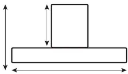
natural_image
Simple line drawing of a rectangular block with two vertical arrows indicating width, no text or symbols present.THERMEX SCANDINAVIA A/S

www.thermex.dk
THERMEX SCANDINAVIA AS

www.thermex.no
THERMEX SCANDINAVIA AB

www.thermex.se
THERMEX SCANDINAVIA S.L.U.

www.thermex.es
THERMEX SCANDINAVIA A/S

www.thermex.fi
THERMEX SCANDINAVIA A/S

www.thermexscandinavia.nl

3 THERMEX THERMEx Tx-SERIES M 900211012207112022
Indhold
| Dansk | 5 |
| Norsk | 17 |
| Svenska | 29 |
| Suomi | 41 |
| Espanol | 53 |
| English | 64 |
4 THERMEX Thermex TX-series M 900211012207112022
INDHOLD
Generel adversel 5
Montering
6
| Type | L(mm) | W(mm) | H(mm) | D(mm) | A(mm) | B(mm) | X(mm) |
| AI410 590 520 60 56 | 560 490 | 50 | |||||
A
D
| A(mm) | B(mm) | C(mm) | D | E |
| 600 min. | 50 min. | 20 min. | Air intake | Air exit 5mm |
4:
- max. 2100 W zone
- max. 1500 W zone
- max. 2100 W zone
- max. 1500 W zone
- max. 3000 W zone
Bridgefunktion
TEKNISKE SPECIFIKATIONER
Modelidentifikation TH1INB 60
Kogezoner 4 zoner
| Type | L(mm) | W(mm) | H(mm) | D(mm) | A(mm) | B(mm) | X(mm) |
| AI410 590 520 60 56 | 560 490 | 50 | |||||
A
D
| A(mm) | B(mm) | C(mm) | D | E |
| 600 min. | 50 min. | 20 min. | Air intake | Air exit 5mm |
IkonBeskrivelse


- max. 2100 W zone
- max. 1500 W zone
- max. 2100 W zone
- max. 1500 W zone
- max. 3000 W zone
Brofunksjon
TEKNISKE SPESIFIKASJONER
INNAN MONTERING/IDRIFTTAGNING
| Type | L(mm) | W(mm) | H(mm) | D(mm) | A(mm) | B(mm) | X(mm) |
| AI410 590 520 60 56 | 560 490 | 50 | |||||
A
D
| A(mm) | B(mm) | C(mm) | D | E |
| 600 min. | 50 min. | 20 min. | Air intake | Air exit 5mm |
- max. 2100 W zone
- max. 1500 W zone
- max. 2100 W zone
- max. 1500 W zone
- max. 3000 W zone
Brofunktion
TEKNISKA SPECIFIKATIONER
Modellidentifiering TH1INB 60
Kokzoner 4 zoner
Matningsspänning 220-240V\~50/60Hz
| Type | L(mm) | W(mm) | H(mm) | D(mm) | A(mm) | B(mm) | X(mm) |
| AI410 590 520 | 60 56 560 | 490 50 |
A
D
| A(mm) | B(mm) | C(mm) | D | E |
| 600 min. | 50 min. | 20 min. | Air intake | Air exit 5mm |
IkonBeskrivelse


- max. 2100 W zone
- max. 1500 W zone
- max. 2100 W zone
- max. 1500 W zone
- max. 3000 W zone
Siltatoiminto
TEKNISET TIEDOT
| Type | L(mm) | W(mm) | H(mm) | D(mm) | A(mm) | B(mm) | X(mm) |
| AI410 590 520 | 60 56 560 | 490 50 |
A
D
| A(mm) | B(mm) | C(mm) | D | E |
| 600 min. | 50 min. | 20 min. | Air intake | Air exit 5mm |
IkonBeskrivelse


- max. 2100 W zone
- max. 1500 W zone
- max. 2100 W zone
- max. 1500 W zone
- max. 3000 W zone
Función de puente
Electrical installation 67
Operation of the device 68
Technical specifications 71
Error codes 71
Cleaning and maintenance 72
Service
73
GENERAL WARNING
- The hob has been developed and produced in accordance with DS/EN 60335-1.
- This product is only intended for use in private homes, if it is used for other purposes, the right to complain is void.
- All installation must be carried out by a qualified technician in accordance with the instructions from Thermex Scandinavia A/S (Thermex) and applicable legislation.
- Thermex disclaims all liability for damage caused by incorrect installation, assembly, use or incorrect settings.
BEFORE ASSEMBLY/COMMISSIONING
- Check the unit for transport damage, errors and defects immediately upon receipt.
- Transport damage is reported immediately on receipt to the transport company and Thermex.
- Faults and defects must be reported to Thermex within 8 days of receipt, and at the latest before installation/commissioning.
- Do not store magnetizable objects, e.g. credit cards, calculators and diskettes close to a hot hob, as they may be damaged.
- People with pacemakers should bear in mind that in the immediate vicinity of a switched-on induction hob, a magnetic field arises, which may may affect the pacemaker. In case of doubt, you should contact your doctor.
- When scrapping a hob, you should make sure to cut all the cables right inside the hob so that it cannot be a danger to
- children. Be sure to take the product to an authorized recycling center to ensure environmentally correct disposal. Also consider that the product may contain parts that can be reused.
- NEVER try to put out a fire with water. Instead, switch off the hob and smother the fire, e.g. with a lid or a fire blanket.
- The plate must be extra protected (earthed) cf. the High Current Regulations. The manufacturer/importer cannot be held responsible for damage caused by a missing or damaged earth connection.
-
Never let children play with the hob or use it without adult supervision.
-
Don't forget that a cooking zone gets very hot in use and that it is also hot for some time after it is switched off. Therefore, never leave a pot or pan containing hot oil/hot fat on the cooking zone without keeping an eye on it.
- Never leave the hob unattended when working with fat or oil. Overheated fat or oil can self-ignite and set the hood on fire.
- Fire hazard! If fat or oil starts to burn, never try to extinguish the fire with water. The fire must be smothered with a cloth or with foam from a fire extinguisher.
- The upper plate on your new hob is made of glass ceramic. It is very strong, but can break if you e.g. drop pointed or sharp objects onto it.
- An induction hob must not be installed above an oven that does not have a cooling fan.
- If the plate is installed above a pyrolysis oven, it must not be used during the pyrolysis cleaning of the oven.
- A possibly the drawer directly below the hob must not contain flammable objects, such as spray bottles.
- The hob must not be installed above dishwashers, washing machines, tumble dryers or refrigerators, as the rather high radiant heat from the hob could damage said products.
INSTALLATION
Assembly and installation should only be carried out by qualified personnel who are familiar with applicable building regulations.
Ensure the following before installation begins:
- The surface / table top where the unit is to be mounted must be horizontal and have sufficient space.
- The surface / table top is sufficiently resistant to heat.
- If the unit is mounted above an oven, the oven must have a built-in cooling fan or be insulated.
- If there is any doubt about the applicable building element, it is recommended to consult the local authorities.
• Always use heat-resistant cleaning agents on and around the unit.
• The installation must comply with the applicable rules and standards for installation, as well as the space requirements around the unit.
Location of the device:
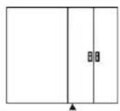
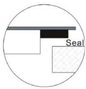
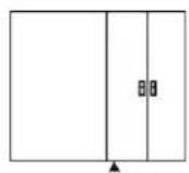
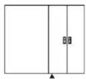
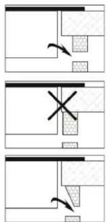
Cut out the hole in the table top according to the sizes shown in the drawing.
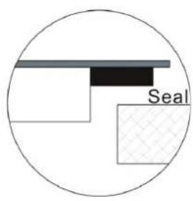
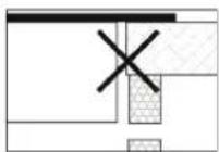
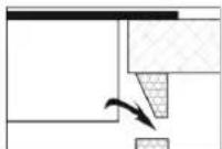
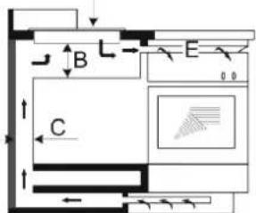
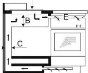
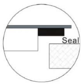
For installation and use of the hob, there should be at least 50 mm of space around the hole. This is to protect the table top material from the high heat of the unit.
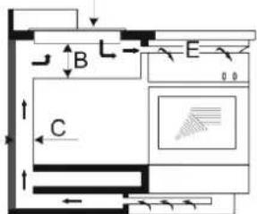
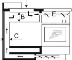
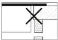
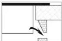
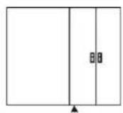
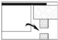
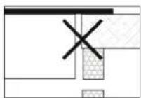
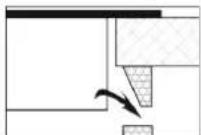
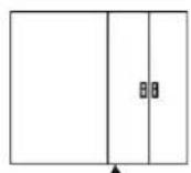
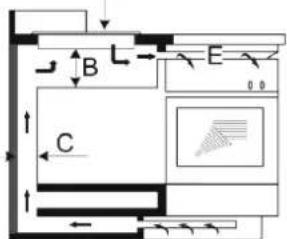
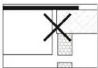
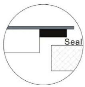
Make sure that the hob is well ventilated and that the air inlet and outlet are not blocked. Make sure the hob is in good working condition. As shown below.
If the hob is installed above an oven, the oven must have a built-in cooling fan.
The installation must comply with all clearance requirements and applicable standards and regulations.
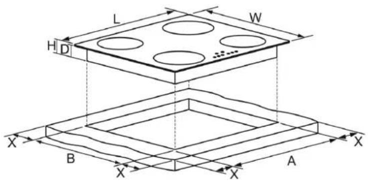
| Type | L(mm) | W(mm) | H(mm) | D(mm) | A(mm) | B(mm) | X(mm) |
| AI410 590 520 | 60 56 560 | 490 50 |
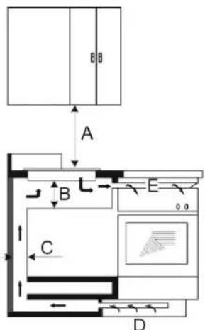
| A(mm) | B(mm) | C(mm) | D | E |
| 600 min. | 50 min. | 20 min. | Air intake | Air exit 5mm |
natural_image
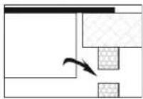
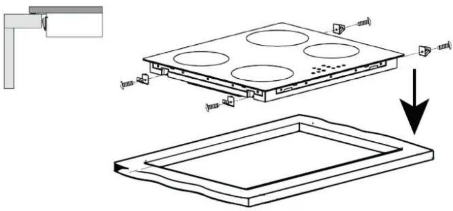
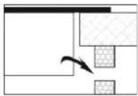
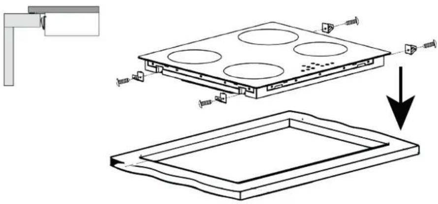
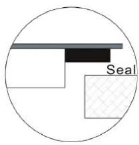
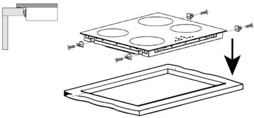
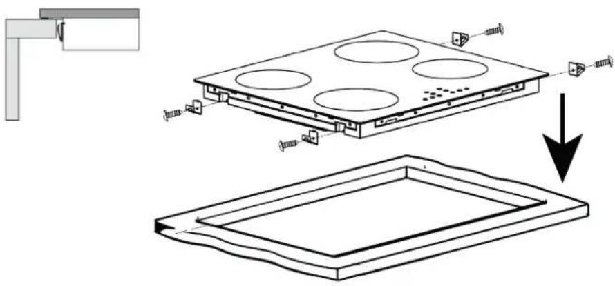
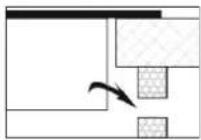
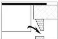
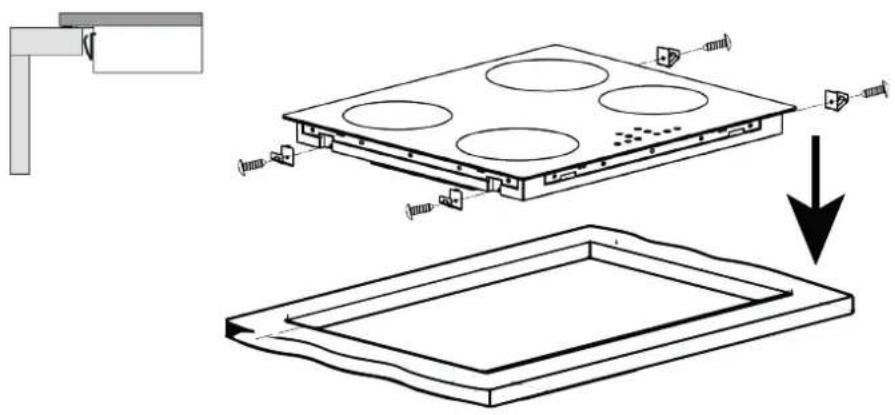
Technical diagram showing a component assembly with mounting bracket and internal structure, no text or symbols presentFit the brackets to the side of the unit as shown in the illustration. The fittings ensure a tight fitting, and the unit sits stably in the hole.
The unit is mounted in the hole in the table top and lightly pressed down so that a tight contact is ensured.
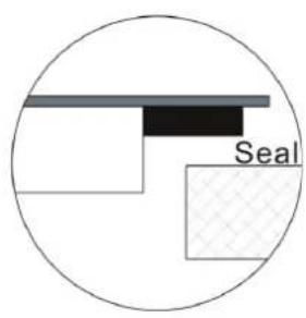
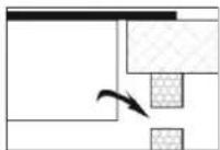
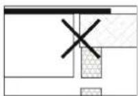
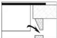
If the unit is mounted above cupboards or drawers, a heat-protective barrier should be fitted between the underside of the unit and the cupboard/drawer.
ELECTRICAL INSTALLATION
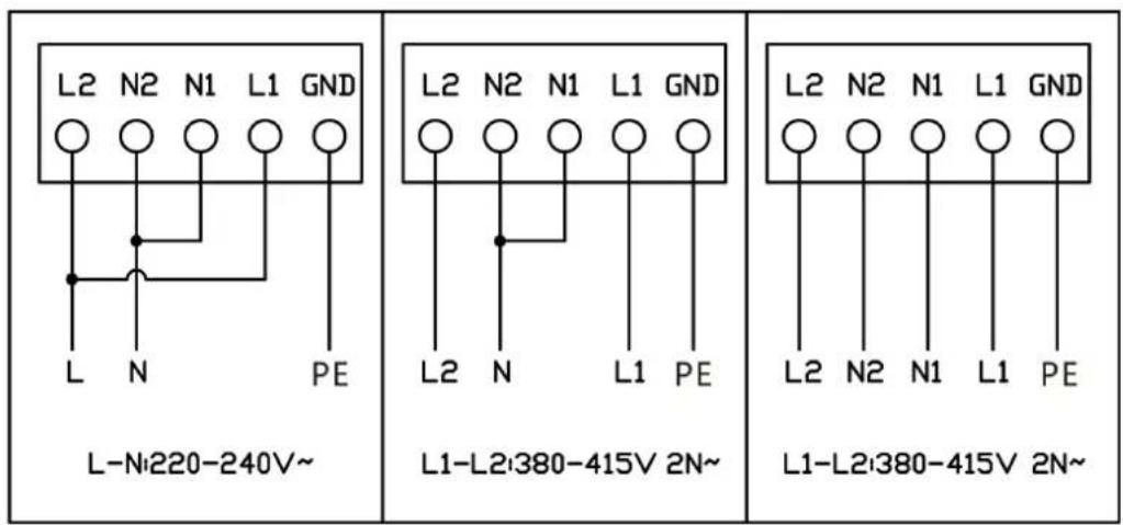
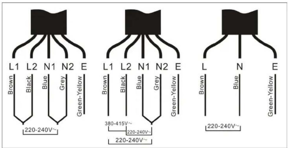
Connection should only be carried out by qualified personnel who are familiar with the applicable building element.
Before connection, it should be ensured that the mains to which the device is to be connected is suitable for the purpose and meets the requirements:
- Check that the mains is suitable for the device's power consumption.
- The mains voltage must match the values specified on the unit's nameplate.
- The power supply cable must be suitable for the load specified on the device nameplate.
- The power supply cable must be free of surrounding hot bodies.
IkonBeskrivelse
 | ON/OFF - Turn the device on/off |
 | CHD100CK Press the button once to lock. Then press the button 3 times. to unlock. |
 | + : Increase the effect on the cooking zone or increase the time on the timer. |
 | - : Reduce the power on the cooking zone or reduce the time on the timer. |
 | Boost function |
 | Timer function. |
 | Select the upper left cooking zone. |
 | Select the lower left cooking zone. |
 | Select the upper right cooking zone. |
 | Select the lower right cooking zone. |
 | Display, shows power level on the cooking zone, or possible error code. |
 | Display, shows hours. |
Using the hob:
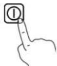
Press the ON/OFF button to activate the hob. All indicators now show "-"
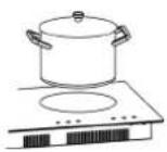
Place a pot/pan on the desired cooking zone. Make sure that the surface of the hob and the underside of the pot/pan are clean and dry.
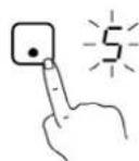
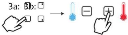
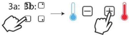
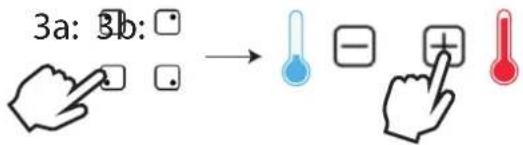
Press the cooking zone selector and the indicator next to it will start to flash.
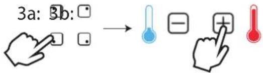
Select the desired heat setting using + and -.
If a heat setting is not selected within 1 minute, the hob switches off automatically.
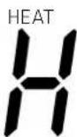
After the use of the hob is finished, there will be excess heat.
When the "H" icon is displayed, it means that the cooking zone is still hot. When the cooking zone has cooled down to a safe temperature, "H" switches off again.
BOOST
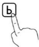
Activate the boost function by pressing "b". Boost provides a significant temporary increase in the heat efficiency of the cooking zone.
Boost can be canceled at any time by choosing a different speed.
LOCK
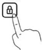
Using the lock function:
Press the lock icon to lock the control panel. The control panel can be unlocked again by pressing the lock icon for 3 seconds. ON/OFF is still active even when the lock function is active.
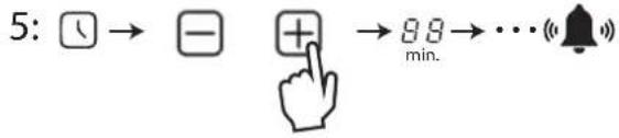
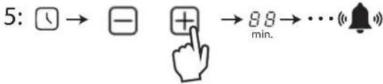
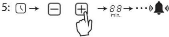
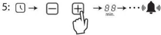
Timer function
| Press the hotplate selector for the hotplate for which the timer is desired. | 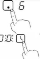 |
| “0” is now shown in the display. | |
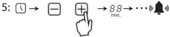
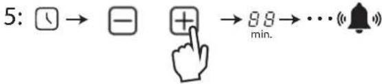
| Set the desired time in minutes using + and -. The two digits must be entered individually. When the first digit is selected, the timer is pressed again and the second digit can now be selected. | 03 |
| The timers can be canceled at any time by following the procedure for hob timers from scratch and setting the time to “0”.After the time is up, switch off the hob. |
Automatic switch off of the hob
The hob is equipped with automatic switching off of the hobs, in the event that a hob is not switched off after use. The following table indicates how long each hotplate is active before it switches off automatically:
| Power level 1 2 3 4 5 6 7 8 9 | |||||||
| Default working time (hour) 8 8 8 4 4 4 2 2 2 |
When the pot/pan is removed from the cooking zone, it switches off automatically after 1 min.
Overview of power level per cooking zone
The table below shows the maximum effect on each of the zones.
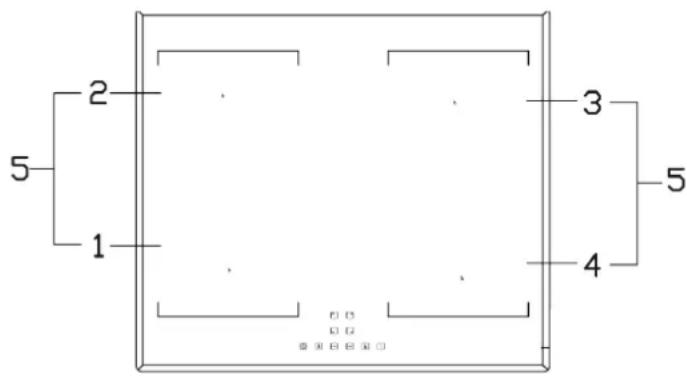
- max. 2100 W zone
- max. 1500 W zone
- max. 2100 W zone
- max. 1500 W zone
- max. 3000 W zone
TECHNICAL SPECIFICATIONS
Model identification TH1INB 60
Cooking zones 4 zones
Supply voltage 220-240V\~50/60Hz
Installed electrical power 7200W
Product size D x W x H (mm) 590×520×60
Built-in dimensions A x W (mm) 560×490
Energy consumption per cooking zone or area calculated per kg EC electric cooking (Wh/kg)
| Bottom | left: | 186.5 |
| Left | up: | 183.4 |
| Right | down: | 192.6 |
| Right | up: | 171.9 |
ERROR CODES
If an abnormality occurs, the induction hob will automatically go into protection mode and display corresponding protection codes:
Problem Possible cause What to do

No pan or pan is not suitable Replace the pan
E2/E3 Abnormal supply voltage
Please check whether the power supply is normal. Switch
on after the power supply is n
E4/E5 Temperature sensor for the IGBT fault
Please contact the supplier.
E7/E8 Temperature sensor error
Please contact the supplier.
E6/E9 Poor heat radiation from the induction hob
Please restart after the induction hob has cooled down.
Eb/EC PCBA communication error
Please contact the supplier.
CLEANING AND MAINTENANCE
DAILY CLEANING
- Surfaces and glass plate are cleaned with a damp cloth with washing-up liquid.
- Lacquered surfaces are cleaned with a damp cloth with sulfo/detergent. NEVER use abrasives.
| What? How Important! | ||
| Everyday dirt on glass (finger-prints, marks, food stains or non-sugary spill-overs on the glass) | 1. Turn off the power to the hob.2. Apply a hot plate while the glass is still warm (but not hot!)3. Rinse and dry with a clean cloth or paper towel.4. Switch on the power to the stove again. | ·When the power to the hob is switched off, there will be a 'no hot surface' indication, but the cooking zone may still be hot! ·Powerful scrubbers, some nylon scrubbers and harsh/abrasive cleaners can scratch the glass. Always read the label to check if your cleaning or scrubbing machine is suitable. ·Never leave cleaning residue on the hob: the glass may become stained. |
| Overboil, melted and hot sugary spill on the glass | Remove these immediately with a fish slicer, palette knife or razor blade scraper suitable for induction glass hobs, but beware of hot cooking zone surfaces:1. Turn off the power to the hob at the wall.2. Hold the blade or utensil at a 30° angle and scrape the dirt or spill onto a cool area of the hob.3. Clean the dirt or spill with a dish cloth or paper towel.4. Follow steps 2 to 4 for 'Everyday dirt on glass' above. | ·Remove stains left by melts and sugary foods or spills as soon as possible. If left to cool on the glass, they can be difficult to remove or even permanently damage the glass surface. ·Cutting hazard: When the safety cover is retracted, the blade of a scraper is razor sharp. Use with extreme caution and always keep safe and out of the reach of children. |
| Spill on the touch control | 1. Turn off the power to the hob.2. Absorb the spill.3. Wipe the touch control area with a clean damp sponge or cloth.4. Dry the area completely with a paper towel.5. Switch on the power to the hob again. | The hob may beep on and off by itself and the touch buttons may not work while there is liquid on them. Be sure to wipe the touch control area dry before switching the hob back on. |
SERVICE
Before reporting service on your Thermex produkt, it is important that you read the installation and/or user instructions carefully. It ensures that Thermex can provide you the best possible assistance.
Service department at Thermex can be contacted in preparation to:
• Technical support for installation and installation of your range product.
- Clarification of functionalities in your produkt.
• Service Request during the warranty on your product.
Before a service request during the warranty always try to disconnect the power to the product for about 5 min. Then plug the power back on to see if the problem is corrected.
If the problem is not corrected, disconnect the power supply to the product for one hour. If the product is still not functioning properly, and the troubleshooting charts are reviewed, contact the service department.
NOTE: For inquiries within the warranty, you will be asked for proof of your purchase in the form of a sales receipt. Therefore, always store your sales receipt
Before the request for service within the warranty, it is important to have all the necessary information ready:
- Error Description
- Product/Model
• The type and serial number of the product (on the chassis plate)
• Information of purchase
MILJ∅HENSYN
EMBALLAGE
SKROTNING AF PRODUKTET

The packaging must be disposed of in accordance with local regulations on waste management.
SCRAPPING OF THE PRODUCT

The symbol _1 on the product or accompanying documentation indicates that this product may not be disposed of as household waste but must be delivered to the nearest collection center for the recycling of electrical and electronic equipment.
THERMEX sCandinavia a/s
THERMEX sCandinavia as
Tel. +47 22 21 90 20
www.thermex.no
service@thermex.no
THERMEX sCandinavia aB
Tel. 031 340 82 00
www.thermex.se
info@thermex.se
THERMEX sCandinavia s.l.u.
Noi del Sucre 42 ■ 08840 Viladecans ■ España
Tel. +34 936 373 003
www.thermex.es
info@thermex.es
THERMEX sCandinavia a/s
Puhelin +358 942 454 000
www.thermex.fi
info@thermex.fi
THERMEX sCandinavia a/s
Tel. +31 208088777
www.thermexscandinavia.nl
info@thermex.eu
- THERMEX THERMEx Tx-SERIES M 900211012207112022
- INDHOLD
- Bridgefunktion
- TEKNISKE SPECIFIKATIONER
- Brofunksjon
- TEKNISKE SPESIFIKASJONER
- INNAN MONTERING/IDRIFTTAGNING
- Brofunktion
- TEKNISKA SPECIFIKATIONER
- Siltatoiminto
- Función de puente
- GENERAL WARNING
- BEFORE ASSEMBLY/COMMISSIONING
- INSTALLATION
- ELECTRICAL INSTALLATION
- Using the hob:
- TECHNICAL SPECIFICATIONS
- ERROR CODES
- CLEANING AND MAINTENANCE
- DAILY CLEANING
- SERVICE
- MILJ∅HENSYN
- THERMEX sCandinavia a/s
- THERMEX sCandinavia as
- THERMEX sCandinavia aB
- THERMEX sCandinavia s.l.u.
Brand : Thermex
Model : TH1INB 60
Category : Cooker