Faster 384 DMX - Joystick Sagitter - Free user manual and instructions
Find the device manual for free Faster 384 DMX Sagitter in PDF.


| Product Type | DMX Lighting Controller |
| Brand | Sagitter |
| Model | Faster 384 DMX |
| Category | Joystick |
| DMX Channels | 384 |
| Control Modes | Joystick, faders, buttons |
| Supply Voltage | 110-240V AC, 50/60Hz |
| Power Consumption | 30W |
| Dimensions (W x D x H) | 482 x 200 x 90 mm |
| Weight | 3.5 kg |
| Display | LCD screen |
| Joystick | 3-axis for pan/tilt control |
| Memory | 384 programmable scenes |
| Output | DMX512 via XLR connectors |
| MIDI | Optional |
| Safety Certifications | CE compliant |
| Maintenance | Clean with dry cloth, avoid liquids |
| Repairability | Refer to qualified service technician |
Frequently Asked Questions - Faster 384 DMX Sagitter
User questions about Faster 384 DMX Sagitter
0 question about this device. Answer the ones you know or ask your own.
Ask a new question about this device
Download the instructions for your Joystick in PDF format for free! Find your manual Faster 384 DMX - Sagitter and take your electronic device back in hand. On this page are published all the documents necessary for the use of your device. Faster 384 DMX by Sagitter.
USER MANUAL Faster 384 DMX Sagitter
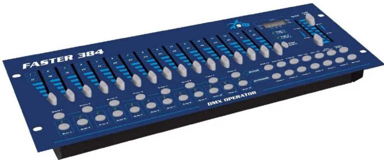
384 Channels DMX controller
SG FASTER384
MANUALE UTENTE USER MANUAL
INDICE:
4. – INSTALLAZIONE, ACCENSIONE ED USO
INSTALLAZIONE
Installare l'apparecchio su una superficie piana o un rack
BANK
EDITING
COPIA DI UNA SCENA
Thank You for choosing one of Our products!
Please refer to the instructions and warnings contained in this user manual, please retain it for future reference.
This manual contains information about the installation and use of the device.
The information contained in this publication has been carefully prepared and checked. However it is not assumed any responsibility for any inaccuracies. All rights are reserved and this document can not be copied, photocopied, reproduced in whole or in part without previous written permission of PROEL. PROEL reserves the right to make, without notice, any aesthetical, functional or design changes or modifications in everyone of its products. PROEL doesn't assume any responsibility for the use or application of the products here described.

The crossed bin symbol, shown on the product or on accompanying documents, indicates that the product should not be disposed with other household waste at the end of the lifecycle. To avoid any damage to the environment, the user is encouraged to separate this product from other kinds of wastes and recycle it responsibly to promote the sustainable reuse of material resources. Home users are encouraged to contact the retailer where they purchased this product or their local government office for details on separate collection and recycling this type of product. Business users are encouraged to contact their supplier and check the terms and conditions of the purchase contract. This product should not be mixed with other commercial waste.

The "F" inside an equilateral reversed triangle means that the product is suitable for mounting on normally flammable surfaces.

The product to which this manual refers comply with the European Directives pursuant to the safety of electrical equipment supplied at low voltage (LVD) and to the Electromagnetic Compatibility (EMC)
2. - SAFETY INSTRUCTIONS
Caution! This product is not suitable for household use.
Please read this manual before installing and applying power to the equipment, follow the safety precautions listed below and observe all warnings in this manual and printed on. Please contact a PROEL distributor for assistance with any questions about how to activate the equipment safely. Contact a qualified technician for any maintenance work not described in this manual.
Do not modify the fixture or install accessories and upgrade kits that are not the Proel original ones.
People involved in the installation and maintenance of the device must:
- Be qualified
- Follow the instructions of this manual in the theaters, in the halls, in the places where the events take place, etc.
MOUNTING SURFACES
The device is suitable for mounting on normally flammable surfaces.
REFERENCE TEMPERATURE
The ambient temperature range of use of the device varies between +5 °C (min) and +40 °C (max), outside of that range the device should not be used.
The maximum temperature of the housing Tb = 80 °C must never be exceeded. Do not block the exhaust fans, ensuring a minimum clearance of 0.5 meters around the ventilation holes.
IP20 PROTECTION RATING
The device is protected against the penetration of solid bodies larger than 12 mm (0,47") in diameter (first digit 2), but not against dripping water, rain, splashes or jets of water (second digit 0). Use only in dry areas. Inside use only. Do not expose the equipment to rain or moisture.
CONNECTION TO THE MAINS
The electrical connection must be carried out by a qualified electrician.
Ensure that the mains frequency and voltage correspond to those for which the equipment is designed, as shown in the electrical data label. This label also shows the power consumption that is necessary to refer to evaluate the maximum number of devices to be connected to the electricity line, in order to avoid power overloading.
If the external power cord of this light is damaged, it must be replaced with a special cord exclusively available from Your PROEL dealer.
Never operate the equipment with covers missing or damaged.
In case of non-use, it is recommended to unplug the equipment from the mains.
MAINTENANCE
Before starting any maintenance or cleaning the product, disconnect the power from the mains and disconnect the power cable from the device. Damaged parts, must be replaced with original spare parts.
IMPORTANT: damages caused by the disregard of this user manual are not subject to warranty.
Keep away from heaters and other heating sources.
Keep away children and amateurs from the device. Never leave the device running unattended. If the device has been exposed to drastic temperature fluctuation (e.g. after transportation), don not switch it on immediately. The arising condensation water might damage your device. Leave the device switched off until it has reached room temperature.
This device falls under PROTECTION CLASS III. It always has to be operated with an appropriate transformer. Check the device, the power cord and transformer from time to time. Make sure that the correct type as that stated on the rear panel.
Always disconnect from the mains, when the device is not in use, or before cleaning it. Maintenance and service operations are only to be carried out by authorized dealers.
Please note that damages caused by manual modifications on the device or unauthorized operation by unqualified persons, are not subject to warranty.
This device is a DMX controller for controlling DMX effects or spots in discotheques, on stages etc. It is allowed to be operated with a direct voltage of DC 12V, minimum 300mA and was designed for indoor use only.
Do not shake the device. Avoid brute force when installing or operating.
When choosing the installation point, please make sure that the device is not exposed to extreme heat, moisture or dust. There should not be any cables lying around. Your endanger your own and the safety of others.
Operate this device only after having familiarized with its functions. Do not permit operation by persons not qualified for operating the device. Most damages are the result of unprofessional operation.
Please use the original packaging if the device is to be transported.
Please consider that unauthorized modifications on the device are forbidden due to safety reasons.
If this device will be operated in any way different to the one described in this manual, it may suffer damages and the guarantee becomes void. Furthermore, any other operation may lead to dangers like short circuit, burns, electric shock, etc.
3. - OPENING AND CONTROL
Carefully open the package, check the content and make sure that all the parts are present and are in good condition. In cases where some parts are not present or are damaged, immediately contact Your supplier and retain the packaging for verification.
| WARNING!If the product has been exposed to drastic temperature changes, let the unit turned off until it reaches room temperature because the presence of condensation can damage the product if it is turned on. |
Verify that the box contains the following items:
N° 1 SG FASTER384
N° 1 Power supply unit
N° 1 User Manual
4. – INSTALLATION, SWITCH ON AND USE
INSTALLATION
Install the device on a plane surface or install it in a rack.
Rack installation: this device is built units rack. The rack you use should be a double door rack where you can open the front panel and the rear panel. The rack should be provided with a cooling fan. When mounting the device into the rack, please make sure that there is enough space around the device, so that the hot air can be passed on. Steady overheating will damage your device. You can fix the controller with four screws M6 in the rack.
Connect the connection cable of the power unit with the DC in socket. Plug the power unit into your outlet.
SOUND CONTROL
The sound control works via built-in microphone.
DMX-512 CONNECTION WITH THE PROJECTORS
The wires must not come into contact with each other, otherwise the fixtures will not work at all, or will not work properly.
Only use a stereo shielded cable and 3-pin XLR plugs and connectors, in order to connect the controller with the fixture or one fixture with another.
OCCUPATION OF THE XLR-CONNECTION:
DMX-output
XLR mounting socket
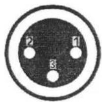
1: ground 2: signal (-) 3: signal (+)
DMX-input
XLR mounting socket
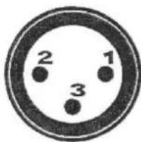
1: ground 2: signal (-) 3: signal (+)
You can adjust the XLR polarity via the DMX polarity selector.
BUILDING A SERIAL DMX CHAIN:
connect the DMX output of the device with the DMX input of the nearest projector. Always connect one output with the input of the next fixture until all fixtures are connected.
CAUTION:
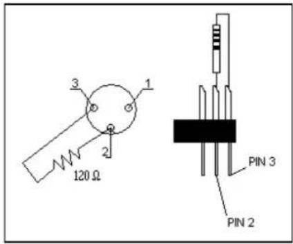
For all installation, having long signal cables or in the presence of electrical noise, for example a discotheque, it is recommended practice to use a DMX terminator: this assist in preventing corruption of the digital control signal by external noise. The DMX terminator is simply an XLR connector with a 120Ω (Ohm) resistor connected across pins 2 and 3, which is then plugged into the DIGITAL THRU socket on the last projector in the chain. The connection are illustrated on the right.
PROJECTOR ADDRESSING:
Please note that the DMX operator assigns the DMX starting addressed every 20 steps. You have to address every projector to the respective starting address. Otherwise the channel assignment. Will not be correct. All projectors with the same starting address work synchronically.
| Projector | Starting address | Projector | Starting address | Projector | Starting address | ||
| 1 | 1 | 5 | 129 | 9 | 257 | ||
| 2 | 33 | 6 | 161 | 10 | 289 | ||
| 3 | 65 | 7 | 193 | 11 | 321 | ||
| 4 | 97 | 8 | 225 | 12 | 353 |
CHANNEL SETTING
This device can control 12 scanners, each up to 32 channels.
BUTTONS DESCRIPTION
| SCANNERS 1-12 buttons | select 12 projectors1 = DMX 001 until 0322 = DMX 033 until 0643 = DMX 065 until 0964 = DMX 097 until 1285 = DMX 129 until 1606 = DMX 161 until 1927 = DMX 193 until 2248 = DMX 225 until 2569 = DMX 257 until 28810 = DMX 289 until 32011 = DMX 321 until 35212 = DMX 353 until 384 |
| SCENES buttons | 8 scenes can be stored in each BANK (1)total 30 BANKS |
| SLIDERS 1-8 / 9-16 | DMX output in combination with SCANNERS buttons 1-12PAGE A = output 1-16PAGE B = output 17-32 |
| PAGE SELECT button | Button to select between PAGE A and PAGE B |
| SPEED slider | stand time: between one scene and another scene |
| FADE slider | fade time: between one scene and another scene (*) |
| BANK UP/DOWN button | select the BANK number from 01 to 30 |
| PROGRAM button | enter or exit Program mode. Press and hold |
| MIDI / ADD button | to REC one scene in program mode (1)MIDI not active |
| AUTO / DEL button | AUTO (it works out from program mode) to play a sequence of scenes in automatic mode (3)DEL (it works under program mode) to delete one scene (4) |
| MUSIC / BANKCOPY button | MUSIC (it works out of program mode) to play a sequence of scenes in sound mode (audio trigger) (5)BANKCOPY (it works under program mode) to copy one bank (6) |
| TAPSYNC / DISPLAY button | TAPSYNC (it works out of program mode) to set the speed time to play a sequence of scenes in automatic mode. The time will be fixed by pressing 2 times this button. The time will follo the speed of these 2 pressing DISPLAY to see maually the steps inside a CHASE |
| CHASE 1 - 6 buttons | each chase is a container of scenes from different banks. Each chase max 240 scenes (2) |
| BLACKOUT button | general blackout |
(*)
| FADE SLIDER ASSIGN | |
| 1 | Switch OFF the controller |
| 2 | Press and hold BLACKOUT + TAPSYNC |
| 3 | Switch ON the controller |
| 4 | Press TAPSYNC in order to select A or P |
| 5 | Press at the same time the buttons BLACKOUT + TAPSYNC to save the settings |
| A: FADE slider active for all the channels | |
| P: FADE slider not active | |
OPERATION
| (1) | RECORD A SEQUENCES OF SCENES | BANK | RECORD | |
| 1 | Enter in program mode (press and hold - little led blinks in the display) | |||
| 2 | Select the desired Bank (1 - 30) (last 2 digits on the right on the display) | |||
| 3 | Select one by one the scanners used in the step and configure one by one (only ONE SCANNER BUTTON ON) | |||
| 4 | When the total configuration is finished, switch ON all the scanners used | |||
| 5 | press ADD and after press SCENE 1. All the leds in the controller will blink | |||
| 6 | repeat the points 3 - 4 - 5 maximum until SCENE 8 (8 scenes in each Bank) | |||
| 7 | Repeat the points 2 -3 - 4 - 5 - 6 maximum until Bank 30 | |||
| (2) | RECORD A SEQUENCES OF SCENES ONE CHASethis procedure ONLY AFTER PROCEDURE (1) | CHASE | ||
| 1 | Enter in program mode (press and hold - little led blinks in the display) | |||
| 2 | Select the chase where you want store the scenes (first digit on the left on the display) | |||
| 3 | All the scanners buttons OFF | |||
| 4 | select the bank where is the desired scene | |||
| 5 | press the desired scene (between 1 and 8) | |||
| 6 | press ADD | |||
| 7 | repeat points 4 - 5 - 6 until finished the sequence in the chase (max 240 scenes) | |||
| (3) | PLAY SCENES IN AUTOMATIC MODE | BANK | PLAY | |
| 1 | Press AUTO button (little led on the display) | |||
| 2 | Select Bank with UP / DOWN buttons | |||
| 3 | Set the desired Speed and Fade | |||
| (5) | PLAY SCENES IN MUSIC MODE | |||
| 1 | Press MUSIC button (little led on the display) | |||
| 2 | Select Bank | |||
| 3 | the sequence will be played with music trigger | |||
| (3) | PLAY SCENES IN AUTOMATIC MODE | CHASE | ||
| 1 | Press AUTO button (little led on the display) | |||
| 2 | Select CHASE with relative button | |||
| 3 | Set the desired Speed and Fade | |||
| (5) | PLAY SCENES IN MUSIC MODE | |||
| 1 | Press MUSIC button (little led on the display) | |||
| 2 | Select CHASE | |||
| 3 | the sequence will be played with music trigger | |||
| TEST PROGRAM | BANK | TEST PROGRAM | ||
| 1 | Enter in program mode (press and hold - little led blinks in the display) | |||
| 2 | Select Bank with UP / DOWN buttons | |||
| 3 | Push each scene in this bank | |||
| TEST PROGRAM | CHASE | |||
| 1 | Enter in program mode (press and hold - little led blinks in the display) | |||
| 2 | Select CHASE with relative button | |||
| 3 | Press Display button (led ON in the display) | |||
| 4 | See each step with UP / DOWN buttons | |||
MODIFY SCENE
| 1 | Enter in program mode (press and hold - little led blinks in the display) |
| 2 | Select Bank with UP / DOWN buttons |
| 3 | Select one by one the scanners used in the step and configure one by one (only ONE SCANNER BUTTON ON) |
| 4 | When the total configuration is finished, switch ON all the scanners used |
| 5 | press REC and after press the button of the scene to modify (overwrite). |
COPY SCENE
| 1 | Enter in program mode (press and hold - little led blinks in the display) |
| 2 | Select source Bank with UP / DOWN buttons |
| 3 | Select the scene to copy |
| 4 | Press ADD |
| 5 | Select destination Bank with UP / DOWN buttons |
| 6 | Select the scene destination (all leds blink) |
BANK
EDITING
(4)
| DELETE A SCENE | |
| 1 | Enter in program mode (press and hold - little led blinks in the display) |
| 2 | Select Bank with UP / DOWN buttons where the scene will be deleted |
| 3 | Press and hold DEL button + press scene to delete |
| 4 | Release Scene and release DEL |
(6)
| COPY BANK | |
| 1 | Enter in program mode (press and hold - little led blinks in the display) |
| 2 | Select source Bank with UP / DOWN buttons |
| 3 | Press ADD |
| 4 | Select destination Bank with UP / DOWN buttons |
| 5 | Press BANKCOPY (all leds blink) |
INSERT or COPY or DUPLICATE SCENE
| 1 | Enter in program mode (press and hold - little led blinks in the display) |
| 2 | Select CHASE where the scene will be inserted |
| 3 | Select Bank with UP / DOWN buttons |
| 4 | Press DISPLAY button |
| 5 | Press UP/DOWN buttons to select the scene AFTER the scene will be inserted |
| 6 | Press ADD |
| 7 | Select the bank where is the source scene |
| 8 | Press scene button (source) |
| 9 | Press ADD (all leds blink) |
(4)
DELETE A SCENE
| 1 | Enter in program mode (press and hold - little led blinks in the display) |
| 2 | Select CHASE where the scene will be deleted |
| 3 | Press DISPLAY button |
| 4 | Select the SCENE to delete with UP/DOWN buttons |
| 5 | Press DEL (all leds blink) |
(6)
COPY BANK
| 1 | Enter in program mode (press and hold - little led blinks in the display) |
| 2 | Select CHASE where the complete bank will be copied |
| 3 | Select Bank to copy with UP / DOWN buttons |
| 4 | Press BANKCOPY |
| 5 | Press ADD (all leds blink) |
(4)
DELETE ONE CHASE
| 1 | Enter in program mode (press and hold - little led blinks in the display) |
| 2 | Select CHASE to delete |
| 3 | Press and hold DEL button + press CHASE to delete |
| 4 | Release CHASE and release DEL |
(4)
DELETE ALL THE CHASES
| 1 | Switch OFF the controller |
| 2 | Press and hold BANK DOWN + DEL |
| 3 | Switch ON the controller (al leds blink) |
| 4 | ALL THE CHASES WILL BE REMOVED BUT NOT THE SCENES |
CHASE
EDITING
| DELETE ALL | |
| 1 | Switch OFF the controller |
| 2 | Press and hold BANK DOWN + PROGRAM |
| 3 | Switch ON the controller (al leds blink) |
| 4 | ALL WILL BE DELETED |
5. - MAINTENANCE
To ensure optimal performance, the unit must be frequently cleaned. Unplug the device from the mains. Use a vacuum cleaner or an air compressor and a soft brush to remove the dust deposited.
Any damaged part, must be replaced with original spare parts.
6. - TECHNICAL SPECIFICATIONS
- DMX controller
- 6 chase with up to 240 scenes can be programmed
• 30 banks each up to 8 scenes (240 scenes) - Copy function for the scenes, program and chase
- Black-out function
• Sound control via built-in microphone
• Power input: 12VDC - 1 A min.
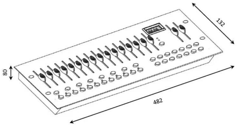
• Dimensions (W x H x D): mm. 482x80x175 - Weight kg 2.8
• 384 control channels for 12 projector each up to 16 channels

- Channels DMX controller
- SG FASTER384
- MANUALE UTENTE USER MANUAL
- INDICE:
- – INSTALLAZIONE, ACCENSIONE ED USO
- INSTALLAZIONE
- - SAFETY INSTRUCTIONS
- MOUNTING SURFACES
- REFERENCE TEMPERATURE
- IP20 PROTECTION RATING
- CONNECTION TO THE MAINS
- MAINTENANCE
- - OPENING AND CONTROL
- – INSTALLATION, SWITCH ON AND USE
- INSTALLATION
- SOUND CONTROL
- DMX-512 CONNECTION WITH THE PROJECTORS
- OCCUPATION OF THE XLR-CONNECTION:
- BUILDING A SERIAL DMX CHAIN:
- CAUTION:
- PROJECTOR ADDRESSING:
- CHANNEL SETTING
- OPERATION
- - MAINTENANCE
- - TECHNICAL SPECIFICATIONS
Brand : Sagitter
Model : Faster 384 DMX
Category : Joystick