FMI-4 - Intercom RTS - Free user manual and instructions
Find the device manual for free FMI-4 RTS in PDF.


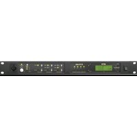
| Product Type | Intercom Master Station |
| Model | FMI-4 |
| Brand | RTS |
| Channels | 4 |
| Dimensions (H x W x D) | 1.75 x 19 x 8 inches (44 x 483 x 203 mm) |
| Weight | 3.5 kg (7.7 lbs) |
| Power Supply | 12V DC, 1A (via external adapter) |
| Power Consumption | 12W max |
| Audio Bandwidth | 300 Hz – 3.4 kHz |
| Audio Output Level | 0 dBm nominal |
| Call Signaling | Visual and audible call indication per channel |
| Intercom Protocol | RTS two-wire partyline compatible |
| Connectors | 4 x XLR-3 (channel), 1 x XLR-4 (program), 1 x RJ45 (external control) |
| Controls | Volume, call button, channel select, mic on/off |
| Indicators | LED per channel for call and active |
| Environmental Temperature | 0°C to 40°C (32°F to 104°F) |
| Humidity | 5% to 90% non-condensing |
| Mounting | 19-inch rack mount, 1U |
| Included Accessories | Power adapter, rack ears, user manual |
| Maintenance | Clean with dry cloth; avoid liquids |
| Safety | Use only supplied power adapter; keep away from moisture |
| Spare Parts & Repairability | Contact RTS authorized service center |
Frequently Asked Questions - FMI-4 RTS
User questions about FMI-4 RTS
0 question about this device. Answer the ones you know or ask your own.
Ask a new question about this device
Download the instructions for your Intercom in PDF format for free! Find your manual FMI-4 - RTS and take your electronic device back in hand. On this page are published all the documents necessary for the use of your device. FMI-4 by RTS.
USER MANUAL FMI-4 RTS
Control Software Technical Manual
PROPRIETARY NOTICE
The product information and design disclosed herein were originated by and are the property of Bosch Security Systems, Inc. Bosch reserves all patent, proprietary design, manufacturing, reproduction, use and sales rights thereto, and to any article disclosed therein, except to the extent rights are expressly granted to others.
COPYRIGHT NOTICE
Copyright 2017 by Bosch Security Systems, Inc. All rights reserved. Reproduction, in whole or in part, without prior written permission from Bosch is prohibited.
*All other trademarks are property of their respective owners.
WARRANTY AND SERVICE INFORMATION
For warranty and service information, refer to the appropriate web site below:
RTS Intercoms ...... www.rtsintercoms.com/warranty
RTS Digital
RTSTW
AudioCom
RadioCom
Intercom Headsets
CUSTOMER SUPPORT
Technical questions should be directed to:
Customer Service Department
Bosch Security Systems, Inc.
www.telex.com
TECHNICAL QUESTIONS EMEA
Bosch Security Systems Technical Support EMEA
http://www.rtsintercoms.com/contact_main.php
DISCLAIMER
The manufacturer of the equipment described herein makes no expressed or implied warranty with respect to anything contained in this manual and shall not be held liable for any implied warranties of fitness for a particular application or for any indirect, special, or consequential damages. The information contained herein is subject to change without prior notice and shall not be construed as an expressed or implied commitment on the part of the manufacturer.
| THE LIGHTNING FLASH AND ARROWHEAD WITHIN THE TRIANGLE IS A WARNING SIGN ALERTING YOU OF “DANGEROUS VOLTAGE” INSIDE THE PRODUCT. | CAUTION: TO REDUCE THE RISK OF ELECTRIC SHOCK, DO NOT REMOVE COVER. NO USER-SERVICEABLE PARTS INSIDE. REFER SERVICING TO QUALIFIED SERVICE PERSONNEL. | THE EXCLAMATION POINT WITHIN THE TRIANGLE IS A WARNING SIGN ALERTING YOU OF IMPORTANT INSTRUCTIONS ACCOMPANYING THE PRODUCT. |
| SEE MARKING ON BOTTOM/BACK OF PRODUCT. | ||
WARNING: APPARATUS SHALL NOT BE EXPOSED TO DRIPPING OR SPLASHING AND NO OBJECTS FILLED WITH LIQUIDS, SUCH AS VASES, SHALL BE PLACED ON THE APPARATUS.
WARNING: THE MAIN POWER PLUG MUST REMAIN READILY OPERABLE.
CAUTION: TO REDUCE THE RISK OF ELECTRIC SHOCK, GROUNDING OF THE CENTER PIN OF THIS PLUG MUST BE MAINTAINED.
WARNING: TO REDUCE THE RISK OF FIRE OR ELECTRIC SHOCK, DO NOT EXPOSE THIS APPARATUS TO RAIN OR MOISTURE.
WARNING: TO PREVENT INJURY, THIS APPARATUS MUST BE SECURELY ATTACHED TO THE FLOOR/WALL/RACK IN ACCORDANCE WITH THE INSTALLATION INSTRUCTIONS.
| ~ | This product is AC only. |
| CE |
Important Safety Instructions
- Please read this manual carefully.
- Please keep this operating manual in a safe place.
- Heed all warnings.
-
Follow all instructions.
-
This device may only be used in accordance to the information provided in this operating manual. Ensure that all recommendations, especially the safety recommendations as detailed in this operating manual, are followed before and during the usage of the device.
-
Do not use this device near water, for example, in humid or damp rooms.
-
Clean only with a dry cloth.
-
Do not block or cover any ventilation slits. Install the device in accordance with the operating manual.
-
Do not install or place the device near any heat source such as radiators, power-amplifiers, or any other heat producing equipment.
-
Protect the power cored from being stepped on, crushed, pinched, or damaged in any other way. Pay special attention to plugs and sockets of the device.
-
Never switch on power amplifiers before the complete system is stable and the level meters of the OPTOCORE CONTROL software indicate a normal level.
-
Do not place this device on an unstable table, tripod, cart, etc. The device may fall, causing serious damage to the device.
-
The device can be disconnected from the power supply by pulling the plug. These must be freely accessible at all times. The should be disconnected during lightning storms or when unused for long periods of time.
-
The device must be grounded; any disconnection of the grounding is not permitted.
-
The internal components of the switched-mode power supplies operate at very high voltages. Coming into contact with them can lead to considerable electric shock, which may result in death.
-
Only use attachments specified by the manufacturer.
-
This device contains no user serviceable parts: only refer to authorized, qualified service personnel for any servicing.
-
Your warranty will be voided if you tamper with the internal components.
Table
of
Contents
Control Software Technical Manual 1
Important Safety Instructions 3
Control Software Installation and Operation 3
Control Software Installation ....3
Workstation, Client And Server Installation Configurations 3
Software Installation 4
Configuration 5
Optocore Network Configuration 5
Device ID and Network Input Setup 7
Software Local Settings 8
Word Clock Setup 8
RS-485 Setup 9
Ethernet Setup 10
Port setup 10
MADI Setup: 10
Device Writing 11
Routing Audio 13
Routing Audio Using the Device's Input/Output Page 13
By Matrix ID 13
By Channel Name 14
Routing Audio Using The Matrix 15
Routing Audio - Set Multiple Channels 16
Send Routing to the Optocore Network 16
Going Online 16
Firmware Upgrade 17
Entering Upgrade Mode 18
Upgrade procedure 18
Troubleshooting 19
Notes 21
2 Control Software
Control Software
Installation and Operation
| IMPORTANT: | Do not connect Optocore devices before configuring device IDs and basic local settings (such as Sample Rate) using the Control software.Do not connect the Optocore network to other devices until its configuration, operation, levels and signal flow. |
Control Software Installation
Workstation, Client And Server Installation Configurations
The Control Software has three different installation setup options:
Workstation Recommended if only one computer is used to control the Optocore network.
Client - Server Recommended if multiple computers (clients) are used to control the Optocore network.
Client Recommended if the client is not physically connected to the Optocore network.

flowchart
graph TD
    A["LAN"] --> B["Server"]
    B --> C["Client 1"]
    B --> D["Client 2"]
    B --> E["Client 3"]
    B --> F["Client 4"]
    B --> G["Client 5"]
    A --> H["Optocore Network"]
FIGURE 1. Client Server System Diagram
4 Control Software
The server allows remote clients to communicate to the Optocore network. All remote clients can manage the Optocore network through the server as long as they are connected to the same LAN network.
User accounts and access control can be setup using the client/server software.
IMPORTANT: The computer acting as a Workstation or a Server must be physically connected to the Optocore Network using USB or Ethernet connection.
Software Installation
IMPORTANT: The versions of the firmware and Control software must match exactly or communications between the workstation and the FMI Series device will not work.
NOTE: The Control Software and the FMI Family firmware can be downloaded at www.optocore.com. The Control Software must be V2.21.027 or later.
To install the control software, do the following:
- Start the software installation program.
- Select the Workstation radio button, Client Only radio button, or Client and Server radio button which fits the installation you are performing.
Setup type
Click the Setup you prefer then click Next.

Workstation
Select this option when you want to run Optocore in Workstation Mode. This is the preferred installation if multiple Clients are not needed.

Client only
Install Client software. Select this option when this computer is a remote client and is not directly connected to Optocore devices.

Client and Server
Install Client and Server Software. Select this option when this computer is a local client and is directly connected to Optocore devices.
NOTE: Depending on the computer's operating system, the installation wizard may need to be completed in Run as Administrator mode. The software is installed to the C:\Program Files\Optocore folder by default.
If you want to keep the previous software version, change the name of the folder containing the earlier software version before running the installer.
Configuration
Once the software is installed, the connection (USB, etc) between the workstation (or server) to the Optocore network must be configured using the Server Options window.
Once an IP Address has been assigned to the unit, then the Ethernet port becomes available.
IMPORTANT: The configuration parameters should be set before you connect the system and begin using the application.
Optocore Network Configuration
Each Optocore device in the network must have a unique ID number.
To set up an ID, do the following:
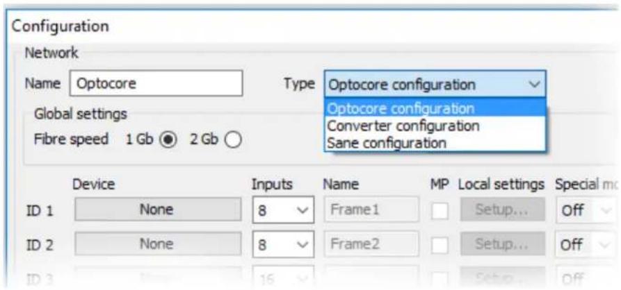
- From the Set drop down menu, select Configuration.
The Configuration window appears.

- In the Name field, enter the network name (i.e., Optocore).
- From the Type drop down menu, select Optocore configuration.
6 Control Software
IMPORTANT: The fiber speed should be consistent across all of the multiplexers in the system. The simplest way to do this is to set required values and then use Write command for each device.
- From the Global Settings group box, select either the 1Gb or 2Gb radio button depending on the devices used in the Optocore network.
IMPORTANT: When using non-bandwidth optimized fiber cables, operating the network at 2Gb/sec can result in a loss of half the maximum cable length between devices.
- From the Sample rate drop down menu, select the appropriate sample rate for the system.

- Select the System Ethernet check box to enable Ethernet transport on the Optocore network.

Device ID and Network Input Setup
Each Optocore device in the network must be assigned a unique ID number.
NOTE: The order of device ID does not need to relate to physical connections of the network. The lower the ID, the device has higher priority to act as the network's master.
To add an ID to your network, do the following:
- From the Device column, click the None button next to the ID you want to assign. The Select Device window appears.

-
Select the device from the list of devices. The Select Device window closes and the chosen device populates the Device column.
-
From the Inputs drop down menu, select the maximum number of audio inputs needed from the device to the Optocore network.

NOTE: The utilization of the total channel capacity of an Optocore network is determined by the number of inputs from the device to the network. The number of inputs configured for a particular device may differ from its number of available physical inputs in order to optimize the use of available channel capacity.
-
In the Name field, enter the name of your device.
-
Select the MP check box to set additional master priority.
Software Local Settings
The next step in configuring an Optocore network is to configure the software local settings of each device, local settings include a selection of word clock sources, RS485, Ethernet and Video transport as well as port configuration.
- In the Configuration window, click the Setup button... for the first device in the Optocore network. The Software Local Settings window appears.

- Configure local settings for each device in the system.
IMPORTANT: It is recommended to prepare a full Optocore configuration, including all Local Settings before proceeding to writing the initial configuration to the devices
Word Clock Setup
Select a Word Clock source for the device
Int Internal Word Clock
BNC External Word Clock, requires the Master Priority (MP) to be set in the Configuration window
Auto The device automatically switches to the external Word Clock when present
RS-485 Setup
There are 32 channels of RS-485 available in the network. Each device can input and output four channels. You can set the input channels in banks of four.
The setting and routing of RS-485 and Ethernet can be modified locally or via the network with the Control software. These settings can be adjusted in OFFLINE mode.
| Pinout Auxiliary Port - 4 x RS485 | ||||||||
| RS485 | GND | Please verify the correct polarity of adaptors.Software configurable for duplex (RS485)An adaptor must be constructed forconnectivity to MIDI, GPIO and CAN interfaces | ||||||
| 1 | 2 | 3 | 4 | |||||
| Pin | +1 | 2 | 3 | 4 | 5 | |||
| -6 | 7 | 8 | 9 | |||||
 | D-Sub-9-female Locking system 4-40 acc to 4-40 UNC | |||||||
To set up RS-485, do the following:
- From the Set menu, select Local Settings (when connected locally).
OR
From the Set menu, select Configuration (when offline).
The Local Settings window appears. The number of ports displayed depends on the device. Four RS-485 ports are shown
-
Click the Local Settings Setup button of the device you want to configure.
-
Select a 4-channel serial input block to transmit serial signals from the device to the Optocore network.
The signals are available to every device on the Optocore network.
- From the Port drop down menu, select a channel for Output.
IMPORTANT: You must make sure that no two devices are configured to the same output channels.
- Configure the output as RS485 (for bi-directional serial signal).
Ethernet Setup
To enable Ethernet, do the following:
- From the Set menu, select Configuration.
The Configuration window appears. - Click the Setup button of the device you want to configure Ethernet.
The Software Local Settings window appears.
Under Ethernet Transport Setup Group Box
- Select Local Ethernet to enable Ethernet on the Optocore device.
Under Ethernet Setup Group Box
- From the Setup mode drop down menu, select 24x8.
NOTE: 24x8 denotes that 24 FMI Series panels can be configured in a network, while each FMI panel can have up to eight devices attached to it.
- If Manual is selected, enter the IP Address and Netmask provided by your network administrator.
Port setup
MADI Setup:
If you are using a MADI device, an adapter may be required to convert the format from coax or fiber to RJ45 format. Adapters are available from third party suppliers. The MADI Products section of the Optocore web page (www.optocore.com) lists a number of such interface capable of doing the required conversion.
Device Writing
All devices in the system are configured in the Control Software.
To write the initial configuration to each device, do the following:
- Connect the FM1 Series unit to the network using the USB or Ethernet connectors.
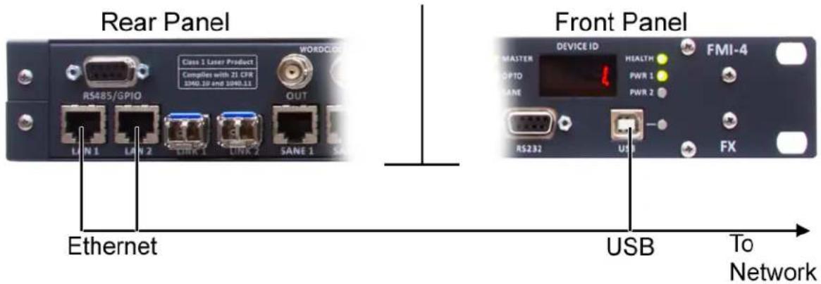
NOTE: The software needs to be configured to connect to devices using USB or Ethernet. From the Administration drop down menu, select Server Options to set the connection method.

12 Control Software
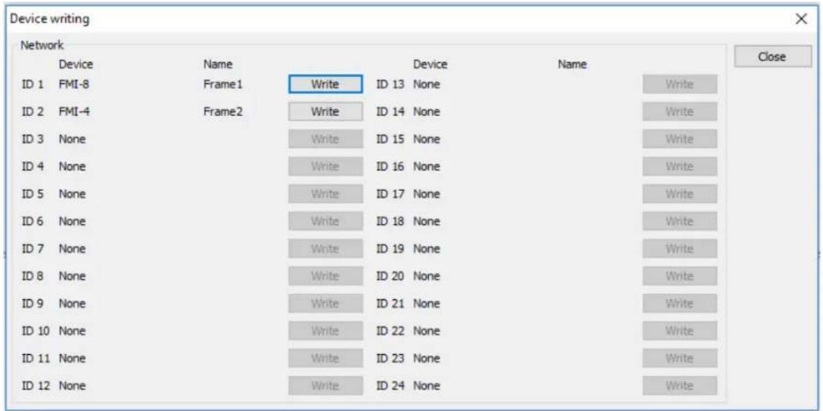
- In the Configuration window, click the OK & Write button. The Device Writing window appears.
-
Click the Write button next to the ID to which you want to send the configuration. This can take a few minutes.
-
Verify the device has the correct ID on the front panel.
IMPORTANT: It is important to ensure the correct ID is written to the correct device. The software will not warn the user if the same ID is being written to multiple devices. Verify the IDs on the physical devices before connecting the system.
- Continue to Write to devices until all devices have been configured. The system is now ready to be connected. The devices can be connected in any order.
Routing Audio
After completing the configuration, audio can be routed between Optocore devices on the network.
In the Control software, individual devices can be selected from the network tree on the left. Once a device is selected, audio can be routed to and from that device.
There are four methods available to route audio in the Optocore Control Software:
- From the device's input tab (by output name or by ID)
- From the device's output tab (by input name or by ID)
- Matrix crosspoints
- Set multiple channels
NOTE: It is recommended to name all devices, inputs and outputs before routing audio.
IMPORTANT: Any input can be routed to multiple outputs. Multiple inputs cannot be routed to one output.
Routing Audio Using the Device's Input/Output Page
By Matrix ID
To route the device using the Matrix ID, do the following
- Select a device from the device tree.
- Select an input (or output) tab in main window.
- Right-click the channel to be routed. A flyout menu appears.
- Select Matrix by ID. A flyout menu appears.
- Select the device to rout.
- Select the output (or input).

By Channel Name
When inputs and outputs are named, routing can be established using the channel names
To route the device using the channel name, do the following:
- Right-click the channel to be routed.
A flyout menu appears.
- From the flyout menu, select Matrix by Name.
A flyout menu appears.
- From the flyout menu, select the channel from the list or enter the name of the output (or input) to route.

Routing Audio Using The Matrix
To route audio using the matrix, do the following:
- From the device tree, select the device from which you want to output signal. The crosspoint window appears.
- Select the Matrix tab.
- Click single crosspoints to route crosspoints individually. OR
Click, hold, and drag your cursor over consecutive crosspoints to route multiple crosspoints at a time.
![OPTOCORE - [d_sample_test.ocs] File Macros View Set Action Administration Help 100% Optocore ID 1 - Frame1 - FMI-8 (2 links) Status 1 - 8Intercom 8/8 Standard ID 2 - Frame2 - FMI-4 (2 links) Inputs Outputs Matrix Port 1 ID 2 — Fr](/content/2026/05/1009267/images/05a5c17764a0e32135cdf516de9a3561d2d28a96b8f155c9b65968fcc1fcf55d.jpg)
NOTE:
- Inputs are in the vertical columns, while outputs of the selected device (from the device tree) are in the horizontal rows.
- The visibility of the matrix view can be adjusted for each device. Go to the Set drop down menu and select Matrix Visibility. Alternatively, set using the Matrix Visibility toolbar buttons (1–24) for the selected device.
Routing Audio - Set Multiple Channels
The Set Multiple Channels window is used to rout and set channel names for multiple channels.

FIGURE 2. Set Multiple Channels Window
- From the device tree, select a device.
- Select the Input or Output tab.
- Specify a range of channels (for example 1-24).
- Specify channel names, routing, gain, pad and phantom power.
- Click OK.
Send Routing to the Optocore Network
Once the audio routing has been set, it can be sent to the Optocore network.
To send the audio routing to the Optocore network, do the following:
From the Action menu, select Send.
NOTE: The Send command, sends all audio routing, gain and phantom power settings to the network. The Send All command sends all network configuration parameters (except for IDs) in addition to the audio routing, gain and phantom power settings to the network.
Going Online
To go online, do the following:
- From the Set menu, select Online Mode.
The current system settings display and load into the system and the Online/Offline indicator turns green. - Verify the operation of the system and all I/O meters indicate the expected levels.
The system is now ready to be used.
Equipment connected to the network can now be turned on and operated.
NOTE: Routing, gain, pad and phantom power control can be operated in real time and any changes are automatically stored in the network devices.
Control Software 17
Firmware Upgrade
IMPORTANT: The versions of the firmware and Control software must match exactly or communications between the workstation and the FMI Series device will not work.
Optocore firmware can be upgraded using a computer running Windows XP/Vista/7/8 with USB, Ethernet, RS232 serial port or an USB to RS232 adapter (COM ports 1 to 4 are supported in the upgrade utility).
FMI Series devices can be upgraded with USB, Ethernet or RS-232.
IMPORTANT: Download the most current firmware from www.optocore.com
The normal connection to upgrade the device is to use a USB cable. As a last resort, if you are unable to successfully upgrade using a USB cable, an RS-232 connection can be used.
To upgrade the firmware, do the following:
- Verify the device is connected via any of the COM1-COM4 ports of the PC.
- Power on the device.
- Double-click OptcrUpgrade.exe.
The Select Device dialog opens.
IMPORTANT: The OptcrUpgrade.exe file can be found at C:\Program Files (x86)\Optocore\V221.
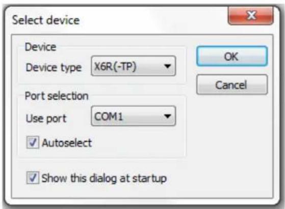
- From the Device Type drop down menu, select the device type to be upgraded.
- From the Use Port drop down menu, select the port the device is connected.
NOTE: Only FMI Series devices are displayed in the Device Type drop down menu when USB or Ethernet ports are selected.
Entering Upgrade Mode
When the device and software are in Upgrade Mode, the current firmware and hardware version are read from the device.

FIGURE 3. User Text 1 shows detailed information about firmware
Upgrade procedure
- From the Upgrade menu, select Erase all settings. All the settings are erased.
- From the Upgrade menu, select Upload Firmware. The firmware begins to upload. When finished, a Succeeded message appears.
- Select the Exit upgrade mode check box.

- Click the OK button. After the device has rebooted, write the Local Settings to the device from the system's configuration file.
Troubleshooting
| Issue Cause Possible Solutions | ||
| System doc not work (not all nodes are connected when software is Online mode), and it is not firmware, device ID, or sampling rates. | The fiber connection is broken or the fiber does not match the transceiver type. | • Visually verify the LEDs on the front panel. If both links on device are connected properly, the OL1 and OL2 LEDs should be lit. If one of the LEDs is not lit, check the fiber connection or check the type of transceiver is being used and if it matches the fiber type. |
| The transmit/receive of the fiber-pair you are using could be incorrect | • The transmit on one multiplexer must connect to the receive side of the other multiplexer and vice versa. If the transmit is talking to transmit, data cannot pass back and forth. Visually confirm this by inspecting the fiber pair you are using.Being careful not to use force to avoid breaking the fiber, carefully unplug the fiber connector from the multiplexer and switch the transmit/receive on one side. Reinsert the fiber connector into the multiplexer. | |
| Configuration software will not connect to the device. | The firmware version of the configuration software does not match the firmware version on the multiplexer | • Verify you are running the latest version of the configuration software. If not, download and install the latest version. For information on how to update the firmware, see “Firmware Upgrade” on page 17. |
| Configuration software will not connect to the device and the popup message “Failed to read device signature” appears. | The device ID on the units may be in conflict. One or more devices may have the same ID. | • Verify all devices have a unique ID. Multiple devices cannot share the same ID.• Reset the device ID as detailed in “Device ID and Network Input Setup” on page 7. |
| System docs not work (not all nodes are connected when the software is in Online mode). | The sampling rates or fiber speed may not correct. Sampling rates and fiber speed need to be the same on all multiplexers. | Using the Control software, verify the sampling rate and fiber speed (1G or 2G) is the same on all multiplexers in the system.Once the sampling rate is set correctly, the front LED that indicates the sampling rate should be indicating the same rate on all multiplexers.There is no LED indication for fiber speed.For more information, see “Device ID and Network Input Setup” on page 7. |
| Cannot connect to the multiplexers over Ethernet. | There is a broadcast storm somewhere on the network. | Verify no external switches are connected with 2 LAN or SANE ports to any of the devices.Verify there is no loopback on any LAN port. If the UP LED blinks there is a fiber fault between the devices. Visually check all the fiber connections. |
| Two devices have the same MAC ID.The FMI Series multiplexers allow you to set the MAC ID of the device. If two devices have the | The Control software can be used to change the MAC ID. Verify each unit has a unique ID.In addition, the Control software has an option for embedding the Ethernet data in the audio stream.From the Administration Menu, select Server Options. | |
| Keypanel does not connect correctly. The Keypanel may be plugged into the wrong connector on the rear of the multiplexer. | Keypanels must be plugged into one of the rear connectors labelled To Keypanel. The matrix must be connected to one of the rear connectors labelled To Matrix. Make sure each device is connected to the right connector.NOTE: Verify the Matrix is connected in the To Matrix section to a connector with an unused number in the To Keypanel section. | |
| Not all of my connections are working. | The matrix may not be correctly configured. | Carefully look over the settings in the input/output matrix, verify all the inputs and outputs are routed the correctly. If a dot is accidentally erased in the matrix, the connection is disabled. |
Notes
Bosch Security Systems, Inc.
12000 Portland Avenue South
Burnsville, MN 55337 U.S.A.
www.boschcommunications.com
- Control Software Technical Manual
- PROPRIETARY NOTICE
- COPYRIGHT NOTICE
- WARRANTY AND SERVICE INFORMATION
- CUSTOMER SUPPORT
- TECHNICAL QUESTIONS EMEA
- DISCLAIMER
- Important Safety Instructions
- Table
- of
- Contents
- Control Software Technical Manual 1
- Control Software Installation and Operation 3
- Troubleshooting 19
- Control Software
- Control Software
- Installation and Operation
- Control Software Installation
- Workstation, Client And Server Installation Configurations
- Control Software
- Software Installation
- Setup type
- Configuration
- Optocore Network Configuration
- Control Software
- Device ID and Network Input Setup
- Software Local Settings
- Word Clock Setup
- RS-485 Setup
- Ethernet Setup
- Under Ethernet Transport Setup Group Box
- Under Ethernet Setup Group Box
- Port setup
- MADI Setup:
- Device Writing
- Control Software
- Routing Audio
- Routing Audio Using the Device's Input/Output Page
- By Matrix ID
- By Channel Name
- Routing Audio Using The Matrix
- NOTE:
- Routing Audio - Set Multiple Channels
- Send Routing to the Optocore Network
- Going Online
- Control Software 17
- Firmware Upgrade
- Entering Upgrade Mode
- Upgrade procedure
- Troubleshooting
- Bosch Security Systems, Inc.
Brand : RTS
Model : FMI-4
Category : Intercom