VLink Virtual Matrix - Intercom RTS - Free user manual and instructions
Find the device manual for free VLink Virtual Matrix RTS in PDF.


| Product Type | Intercom System |
| Model | VLink Virtual Matrix |
| Brand | RTS |
| Form Factor | 19-inch rack mount, 1U |
| Dimensions (W x D x H) | 483 x 250 x 44 mm |
| Weight | 2.5 kg (5.5 lbs) |
| Power Supply | PoE (802.3af) or 12V DC, 15W max |
| Number of Ports | 4 RJ-45 (10/100 Mbps) |
| Protocols | AES67, Ravenna, RTS Matrix |
| Audio Channels | Up to 64 channels |
| Sample Rate | 48 kHz, 24-bit |
| Frequency Response | 20 Hz - 20 kHz |
| Operating Temperature | 0°C to 40°C (32°F to 104°F) |
| Mounting | Rack ears included |
| Key Functions | Virtual matrix routing, intercom integration, audio bridging |
| LED Indicators | Power, Link, Activity per port |
| Maintenance | Keep firmware updated; clean with dry cloth |
| Safety | CE, FCC compliant; use only with approved PoE injector |
| Spare Parts | Power supply, rack ears available as accessories |
| Repair Policy | Contact RTS support for RMA; no user-serviceable parts |
| Warranty | 2 years limited |
Frequently Asked Questions - VLink Virtual Matrix RTS
User questions about VLink Virtual Matrix RTS
0 question about this device. Answer the ones you know or ask your own.
Ask a new question about this device
Download the instructions for your Intercom in PDF format for free! Find your manual VLink Virtual Matrix - RTS and take your electronic device back in hand. On this page are published all the documents necessary for the use of your device. VLink Virtual Matrix by RTS.
USER MANUAL VLink Virtual Matrix RTS
Up to and including version 3.0.0.395

PROPRIETARY NOTICE
The product information and design disclosed herein were originated by and are the property of Bosch Security Systems, Inc. Bosch reserves all patent, proprietary design, manufacturing, reproduction, use and sales rights thereto, and to any article disclosed therein, except to the extent rights are expressly granted to others.
COPYRIGHT NOTICE
Copyright 2011 by Bosch Security Systems, Inc. All rights reserved. Reproduction, in whole or in part, without prior written permission from Bosch is prohibited.
WARRANTY AND SERVICE INFORMATION
For warranty and service information, refer to the appropriate web site below:
RTS ...... www.rtsintercoms.com/warranty
RTSTW ...... www.rtstw.com/warranty
AudioCom......www.telexaudiocom.com/warranty
RadioCom ...... www.telexradiocom.com/warranty
Headsets ...... www.intercomheadsets.com/warranty
CUSTOMER SUPPORT
Technical questions should be directed to:
Customer Service Department
Bosch Security Systems, Inc.
12000 Portland Avenue South
Burnsville, MN 55337 USA
Telephone: 877-863-4169
Fax: 800-323-0498
Info@rtsintercoms.com
Technical Questions EMEA
Bosch Security Systems Technical Support EMEA
http://www.rtsintercoms.com/contact_main.php
Disclaimer
The manufacturer of the equipment described herein makes no expressed or implied warranty with respect to anything contained in this manual and shall not be held liable for any implied warranties of fitness for a particular application or for any indirect, special, or consequential damages. The information contained herein is subject to change without prior notice and shall not be construed as an expressed or implied commitment on the part of the manufacturer.
Table
of
Contents
VLINK SOFTWARE INSTALLATION AND ACTIVATION ....3
Introduction ...... 3
System Requirements .... 3
Hardware 3
Software 3
Network 3
Firewall Requirements 3
Installation 4
Licensing 5
Obtain the System Identification Code 5
Obtain a Valid License Code 7
Activating the VLink Software 8
INTRODUCTION AND CONFIGURATION ...... 11
VLink System Administration ....11
System Requirements ....11
Hardware 11
Software 11
Network 11
System Administration Window 12
System Information Group Box 12
System Information Button 12
Licensee Field 13
Licensed Connections Field 13
License Expiration Field 13
System Status Group Box ....13
System Up Time Field 13
Processor Utilization Field 13
Failover Status 13
Active Connections Field 13
Active Audio Inputs Field 14
Active Audio Outputs Field 14
Trunking Status Group Box 14
Trunking Status Field 14
Active Trunks Window 14
System Configuration Group Box 14
System Settings Button 14
Client Configuration Button 14
Group Configuration Button 14
Remote Configuration Button 14
System Maintenance Group Box 15
Restart System Button 15
Force Failover Button 15
System Statistics Group Box 15
Client Statistics Button 15
SIP Registrations Button 15
Activity Log Button 15
Logout Button 15
Exit Button 15
Remote Configuration Window 16
System Name Column 16
# Column 16
Label Type Column 16
Talk/Listen Name Column 16
Description Column 16
Ext Alpha (8U) Column 16
Ext Alpha (4) Column 17
Restrict Column 17
Port Column 17
Edit Button 17
Remote Configuration Edit Window 17
Label Identification Group Box ....17
Label Type Drop Down Menu 17
Label Description Field 17
Selector Name Field 18
External Alpha (8U characters) Field 18
External Alpha (4 characters) Field 18
Options Group Box 18
Always Show Selector when Off-line Check Box 18
Latch Disable Talk Selector Check Box 18
Selector Assignment Restrictions Group Box 18
No Local Assignment By Administrator Check Box 18
No Local Assignment By User Check Box 18
OK Button 18
Cancel Button 18
System Identification Window 19
Information Group Box 19
System Identification Code Field 19
Upload License File Button 19
Close Button 19
System Settings Window 20
Master System Administrator Login Group Box 21
Login Name Field 21
Login Password Field 21
Primary Server Network Settings Group Box 21
Server IP Address Field 21
Server IP Ports for VLink Client Audio Field 22
Server IP Ports for SIP Data Field 22
Server IP Ports for RTP Audio Base Field 22
Server SIP Domain Name Field 22
Secondary (Failover) Server Network Settings Group Box 22
Server IP Address Field 22
Server IP Ports for VLink Client Audio Field 22
Server IP Port for Failover Data Field 23
Audio Settings Group Box 23
Audio Mix Sample Rate Drop Down Menu 23
Audio Output Level Gain (Post-Mix) Field and Slider 23
Voice Activity Indication Group Box 23
Voice Activity Indication Color Text Button 23
Voice Activity Indication Color Background Button 23
OK Button 23
Cancel Button 23
Client Configuration Window 24
Client List Group Box 24
Client Type Column 24
Talk/Listen Name Column 24
Listen Only Name Column 24
Login Name Column 25
Login Password Column 25
Description Column 25
Latchable Column 25
Ext Alpha (8U) Column 25
Port Column 25
Add Button 25
Edit Button 25
Delete Button 25
Selected Client Group Box 26
Selector Assignments... Button 26
Audio Settings... Button 26
Options... Button 26
All Clients Group Box 26
Default Selector Assignments... Button 26
Default Audio Settings... Button 26
Default Options... Button 26
Client Configuration Add/Edit Window 27
Client Type Drop Down Menu 27
Client Description Field 27
Login Name Field 28
Allow Anonymous Login Check Box 28
Login Password Field 28
Selector Talk/Listen Name: Field 28
Selector Listen Only Name Field 28
External Alpha (8U Characters) Field 28
External Alpha (4 Characters) Field 28
Options Group Box 28
Always Show Selector when Off-line Check Box 28
Latch Disable Talk Selector Check Box 29
Party Line Operation Check Box 29
IFB Destination Check Box 29
ISO Destination Check Box 29
Selector Assignment Restrictions Group Box 29
No Local Assignment By Administrator Check Box 29
No Local Assignment By User Check Box 29
No Remote Assignment By Administrator Check Box 29
No Remote Assignment By User Check Box 29
OK Button 29
Cancel Button 29
VLink Client Configuration Selector Assignments Window 30
Selected Client Group Box ......30
Non-Assigned Selectors Group Box 30
Label Type Column 30
Name Column 30
Description Column 31
Selector Configuration Buttons .... 31
--> Split Talk/Listen --> Button .... 31
----> Talk Only ----> Button ....31
---->Listen Only ----> Button ....31
Remove <---- Button 31
Clear ----> Button 31
Latchable --> Button 31
IFB ----> Button .... 31
ISO ----> Button ....31
Speaker Dim -> Button 31
Hot Key ----> Button 31
Assigned Selectors Group Box 32
Name Column 32
Selector Type Column 32
Selectors to Display per Row Field 32
Selector Activation Method Drop Down Menu 32
Selector Activation Detail Field 32
OK Button 32
Cancel Button 32
Selector Hot Key Window ....33
Hot Key Group Box 33
Alt Check Box 33
Control Check Box 33
Shift Check Box 33
Key Drop Down Menu .... 33
Clear Button 33
OK Button 33
Cancel Button 34
VLink Client Configuration Audio Settings Window 34
Selected Client Group Box 34
Audio Quality Group Box 35
Audio Encoder/Decoder Drop Down Menu 35
Audio Encoder Sample Rate Drop Down Menu 35
Audio Encode Quality Field and Slider 35
Audio Encode Complexity Field and Slider 36
Variable Bit Rate Check Box 36
Audio Transmission Group Box 36
Audio Capture Buffer Size Field and Slider 36
Audio Time Slice Per Packet Field and Slider 36
Jitter Buffer Size Field and Slider 37
Silence Suppression Time Field and Slider 37
Packet Resequencer Depth Field and Slider 37
Audio Levels Group Box 37
Automatic Gain Control Check Box 37
Automatic Gain Control Level Field and Slider 37
Audio Input Level Gain (Pre-Mix) Field and Slider 38
Audio Output Level Gain (Post-Mix) Field and Slider 38
Speakerphone Speaker Dim Reduction Field and Slider 38
Audio Processing Group Box 38
Echo Cancellation Check Box 38
Echo Cancellation Tail Length Field and Slider 38
OK Button 38
Cancel Button 38
VLink Client Configuration Options Window 39
Selected Client Group Box 39
Control Panel Options 39
Hide Disabled Selectors Check Box 39
Hide Selector Legends Check Box 40
Voice Activity Indication Check Box 40
Split Selector Center Zone Check Box 40
Client Options Group Box 40
Voice Activity Detection Time in Ms Field 40
Administration Privileges Check Box 40
Telephone Interface Options Group Box 41
Auto-Answer Check Box 41
SIP Options Group Box 41
Inbound Session Activation Drop Down Menu 41
Inbound Session Deactivation Drop Down Menu 41
Outbound Session Activation Drop Down Menu 41
Outbound Session Deactivation Drop Down Menu 42
Automatic Dial Sequence Field 42
Send SDP With Invite Request Check Box 42
Use SDP for RTP Destination Check Box 42
OK Button 42
Cancel Button 42
VLink Group Configuration Window 43
Group List Group Box 43
Group Type Column 43
Talk/Listen Name Column 43
Description Column 43
Latchable Column 43
Ext Alpha (8U) Column 43
Ext Alpha (4)Column 44
Restrict Column 44
Port Column 44
Add Button 44
Edit Button 44
Delete Button 44
Selected Group Group Box 44
Group Membership Button 44
VLink Group Configuration Add/Edit Window 45
Type Drop Down Menu 45
Description Field 45
Selector Talk Label Field 45
External Alpha (8U Characters) Field 45
External Alpha (4 Characters) Field 46
Options Group Box 46
Latch Disabled Check Box 46
Selector Assignment Restrictions Group Box 46
No Local Assignment By Administrator Check Box 46
No Local Assignment By User Check Box 46
No Remote Assignment By Administrator Check Box 46
No Remote Assignment By User Check Box 46
VLink Group Configuration Membership Window 47
Selected Group Group Box 47
Non-Group Members Group Box 47
Client Type Column 47
Name Column 47
Description Column 47
---> Talk and Listen ---> Button 48
----> Talk Only ----> Button 48
---->Listen Only ----> Button 48
Remove <---- Button 48
Clear ----> Button 48
Group Members Group Box 48
Name Column 48
Mode Column 48
OK Button 48
Cancel Button 48
VLink Client Statistics Window 49
Client Column 49
State Column 49
Duration Column 49
DEC Column 49
DSCD Column 49
SARAE Column 49
SAPLLS 50
SAPLLM Column 50
SAPLSL Column 50
RARBD Column 50
RAPLLS Column 50
RAPLLM Column 50
RAPLSL Column 50
CPU Column 50
IP Address Column 50
Version Column 50
Reset Statistics Button 50
Show Unused Clients Check Box 51
Column Legend... Button 51
Close Button 51
VLink SIP Registrations Window VLink 52
User Name Column 52
Address of Record Column 52
Contact Detail Column 52
Expiration Time Column 52
Close Button 52
Activity Log Window 53
Log Group Box 53
No Scroll Button 53
Close Button 53
VLINK DEVICE INTERFACE 55
VLink Device Interface 55
Installation 55
Configuration 56
Operation 58
BASIC FUNCTIONALITY AND FEATURES 58
All Devices Group Box 59
Login/Logout Button 59
Selected Device(s) Group Box 59
Login/Logout Button 59
Monitor Input Button 59
Monitor Output Button 59
Simulate GPI(s) Button 59
Toggle GPO(s) Button 59
Statistics Button 59
Configure Button 59
Add Button 59
Edit Button 59
Delete Button 59
TROUBLESHOOTING 60
TRUNKING 61
Configure for Trunking 61
Configuring VLink to Trunk 64
Overview 67
Configuring VLink for SIP Devices 68
Configuring SIP Devices for VLink 68
Softphones 68
Hardphones and ATAs 68
NETWORK BANDWIDTH REQUIREMENTS GUIDE 69
Glossary 71
Mobile Devices 73
Introduction 73
System Requirements 73
Hardware Requirements 73
Software Requirement 73
Network Requirements 73
Firewall Requirements 74
Installation 74
Configuration 74
Operation 76
Basic Functionality And Features 76
Talk/Listen Selectors 76
Control Panel Buttons 77
Mobile Device Options Screen 78
Done Button 78
Startup Options 78
Enable Autologin On/Off Slider 78
Display Options 78
Hide Selector Legends On/Off Slider 78
Split Selector Center On/Off Slider 78
Selectors Columns Display Field 79
Audio Options 79
Headset Only On/Off Slider 79
Narrowband (8kHz) Touch point 79
Wideband (16kHz) Touch point 79
Ultra Wideband (32kHz) Touch point 79
Statistics Screen 80
Send Audio Rates (Kbps) Display Field 80
Receive Audio Rates (Kbps) Display Field 80
Send Audio Packet Loss (%) Display Field 80
Receive Audio Packet Loss (%) Display Field 80
NOTES 81
List
of
Figures
FIGURE 1. VLink System Administration Window ......12
FIGURE 2. System Restart Confirmation Message ....15
FIGURE 3. VLink Remote Configuration Window ......16
FIGURE 4. Remote Configuration Edit Window ......17
FIGURE 5. System Identification Code Window .....19
FIGURE 6. System Settings Window ......20
FIGURE 7. VLink Client Data, Audio, SIP Data, RTP Audio Base fields .....21
FIGURE 8. Client Configuration Window ......24
FIGURE 9. Client Deletion Confirmation Message ....25
FIGURE 10. Client Configuration Add/Edit Window ......27
FIGURE 11. VLink Client Configuration Selector Assignments Window ......30
FIGURE 12. Selector Hot Key Window ......33
FIGURE 13. VLink Client Configuration Audio Settings ....34
FIGURE 14. VLink Client Configuration Options Window ......39
FIGURE 15. Selector Legends ......40
FIGURE 16. VLink Group Configuration Window ......43
FIGURE 17. Group Deletion Confirmation ....44
FIGURE 18. VLink Group Configuration Add/Edit Window ....45
FIGURE 19. VLink Group Configuration Membership Window ......47
FIGURE 20. VLink Client Statistics Window 49
FIGURE 21. Client Statistics Legend Window ....51
FIGURE 22. VLink SIP Registrations Window 52
FIGURE 23. Activity Log Window ....53
FIGURE 24. VLink Device Interface ....58
FIGURE 25. VLink LE System Diagram with Traditional Trunking Connection ......62
FIGURE 26. VLink LE System Diagram with MADI-16+ Matrix Connection (Trunking) ......63
FIGURE 27. Client Configuration Window ....64
FIGURE 28. VLink Mobile Device Assignments .....76
FIGURE 29. Mobile Device Options Screen 78
FIGURE 30. Statistics Screen 80
VLink Software Installation and Activation
Introduction
VLink is a non-blocking all software, multi-channel/multi-access intercom over internet protocol based on a dedicated server, multiple client architecture. It is engineered for professional, mission critical communications in broadcast, production, military, aerospace, and government application.
| IMPORTANT: | When you start the VLink Virtual Matrix software for the first time, you will need to get the System Identification of the computer you are running the software, see “Obtain the System Identification Code” on page 5. The System Identification Number is needed to license the software, see “Obtain the System Identification Code” on page 5. |
System Requirements
Hardware
Pentium 4, 2.4GHz or better with 4Gb memory (requirements may be greater depending on system size)
Software
Windows Server 2008 (preferred), Windows Server 2003, Windows XP, Windows Vista, Windows 7
Network
100BaseT connection
See "Network Bandwidth Requirements Guide" on page 69 for Network Bandwidth Requirements
Firewall Requirements
Outbound: Allow TCP connection for data on port 1000 and UDP connection for audio on port 1000
Inbound: Port forwarding TCP and UDP on port 1000 to IP Address server
Installation
NOTE:
- The VLink Virtual Matrix can be run before licensing, however you cannot connect to the control panel or device interfaces.
- If you are using multiple NIC (Network Interface Cards), verify you are using the correct card to run VLink.
To install the VLink Virtual Matrix software, do the following:
- Double-click VLink_Virtual_Matrix_Setup.exe.
The installation wizard begins.
- Accept all the defaults.
NOTE: You must accept the end user license agreement to finish the installation.
![graph TD A["Setup Status"] --> B["The InstallShield Wizard is installing VLink Virtual Matrix"] B --> C["Installing C:\VLink Virtual Matrix.m"] C --> D["1"] D --> E["2"] E --> F["3"] F --> G["4"] subgraph Setup Status H["1: Setup Wizard"] --> I["Cancel"] end subgraph Tools & Conditions J["1: Tools &…](/content/2026/05/1009266/images/7b3fb7709b13969ab876b5a8714829ac9ad4d11e697c0b82ac6ccdd6cebad232.jpg)
- Click Finish.
The VLink Matrix software is installed.
Licensing
To license your VLink System, you need to acquire a valid license file from Technical Service Support. To do so, you must provide your unique System Identification Code, generated automatically when you install the VLink Virtual Matrix, to the contact person listed in Table 1 on page 7.
IMPORTANT:
The System Identification Code is a unique value specific to the computer on which the Virtual Matrix is installed and is not transferable to any other computer. If the server you are running the VLink Virtual Matrix has dual network cards, verify the correct card is chosen before sending the system identification code.
Obtain the System Identification Code
There are two (2) ways to obtain the system identification code.
• From the Virtual Matrix first time logon window
• From the System Identification Code window in the System Administration window
To obtain the system identification code from the virtual matrix window, do the following:
- From the Start menu, select Programs|Intracom|VLink Virtual Matrix.
VLink Virtual Matrix starts.
System Identification Code
![04/01/11 12:51:20 - VLink Virtual Matrix version: 2.3.0.205 04/01/11 12:51:45 - [License] ERROR: No Valid License file ... System Identification Code: 5EFB-678B-92FB-5D57 04/01/11 12:51:45 - Server configuration file: "C:\Program Files\RTS\VCOM\SystemConfiguration.txt" ... # of Conf 04/01/11 12:51:4…](/content/2026/05/1009266/images/3fd7c24710ef4d9ed81285fba19fec6531a3ea7a8518ebe939b9489bf11bc144.jpg)
- Record the System Identification Code to submit for the license code.
To obtain the system identification code from the System Administration window, do the following:
NOTE: System Status fields are color-coded as follows:
• Red indicates a problem
• Yellow indicates a condition needs attention
• Green indicates normal operation
- From the Start menu, select Programs|Intracom|VLink System Administration.
The System Administration Login window appears.
- Click Login.
The System Administration window appears.
- Click the System Information button located in the upper-left hand corner. The System Identification Code window appears.


- Record the System Identification Code to submit for the license code.
Obtain a Valid License Code
To obtain a valid license code, do the following:
Using the licensing contact person information below, send an email to the appropriate contact requesting a license code.
TABLE 1. Licensing Contact Person
| Region Email Contact Name | ||
| Asia (APR Region) alice.onn | @sg.bosch.com Alice Onn | |
| Europe, Africa, Middle East (AMEA Region) | NSOOrderDeskExport.STSEC-LOG@de.bosch.com Susi | Betzenhauser Sabina Basic |
| Americas (AMEC Region) | buv.orders@us.bosch.com | Lisa Wenger Diane Dressel |
IMPORTANT:
When you receive your license code, save it to your desktop for later use.
Activating the VLink Software
To activate the VLink software application, do the following:
NOTE: System Status fields are color-coded as follows:
• Red indicates a problem
• Yellow indicates a condition needs attention
• Green indicates normal operation
- From the Start menu, select Programs|Intracom|VLink System Administration.
The System Administration Login window appears.
- Click Login.
The System Administration window appears.

- Click the System Information button located in the upper-left hand corner. The System Identification Code window appears.
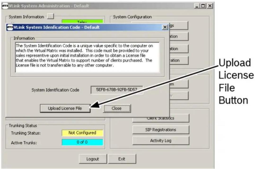
4. Click Upload License File.
A navigation window appears.

-
Navigate to where you saved the VirtualMatrix.key file.
-
Click Open.
The license code is uploaded into the application.
VLink System Administration
VLink is configured via the client-side System Administration application which allows for dynamic configuration from any workstation. This application can also be run on the server hosting the VLink Virtual Matrix and is installed automatically along with it.
System Requirements
Hardware
Dedicated: Pentium Celeron 1.0GHz or equivalent with 1Gb memory
Multipurpose: Pentium 4, 2.0GHz or equivalent with 1Gb memory
Software
Windows XP, Windows Vista, or Windows 7
Network
100BaseT connection
System Administration Window
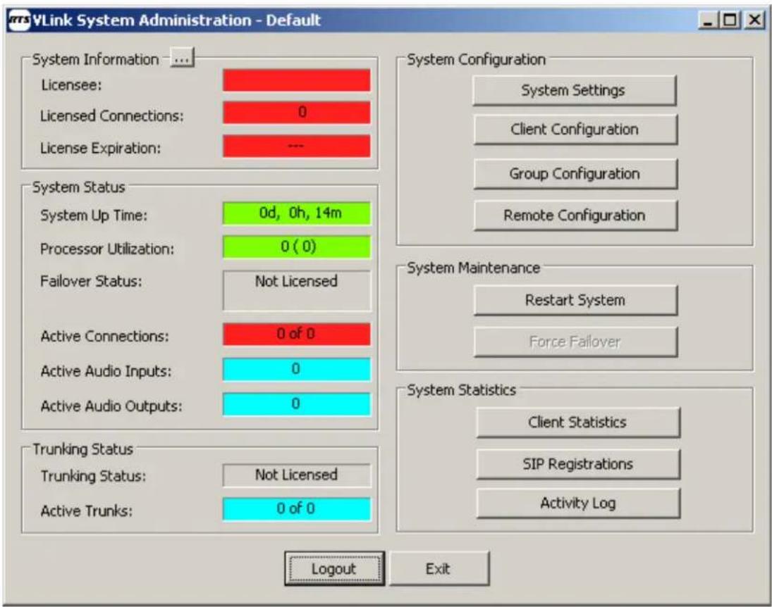
The System Administration window, shown in Figure 31, is the backbone of the VLink System Administrator application. From this window, you can configure system settings, client settings, and group settings, as well as display client statistics, SIP registrations, and activity logs. Also, this window is used to upload license information.
NOTE: System Status fields are color-coded as follows:
• Red indicates a problem
• Yellow indicates a condition needs attention
• Green indicates normal operation

FIGURE 31. VLink System Administration Window
System Information Group Box
The System Information group box displays important software and licensing information.
System Information Button
The System Information button opens the System Identification Code Window. For more information, see “The Remote Configuration Edit window, shown in Figure 31, is used to define the type of trunk being referenced, add a label description, and name the selector reference.” on page 17.
Licensee Field
The Licensee field displays the name of the person or company the software license is issued to.
This field cannot be modified.
Licensed Connections Field
The Licensed Connections field displays the number of licenses granted to the Licensee. The number of licenses dictates the number of simultaneous client connections allowed by the VLink Virtual Matrix.
This field cannot be modified.
License Expiration Field
The License Expiration field displays the date the license will expire. If the license is a permanent license with no expiration date, the field displays - - - (dashes)
NOTE: If you have a temporary licensed copy of the VLink software, you see an expiration date in this field.
This field cannot be modified.
System Status Group Box
The System Status group box is used to view system status variables such as System Up Time, Processor Utilization, Failover Status, Connection Status, Audio Inputs/Output Status.
System Up Time Field
The System Up Time field displays the amount of time in days, hours, and minutes, the VLink system has been running.
This field cannot be modified.
Processor Utilization Field
The Processor Utilization field displays the amount of processor power being used.
This field cannot be modified.
Failover Status
The Failover Status field displays the status of the primary and secondary servers, if applicable. If Failover is not licensed, this field displays Not Licensed. If a secondary server IP Address has not been configured, this field displays Not Configured.
This field cannot be modified.
Active Connections Field
The Active Connections field displays the number of connections currently being used.
This field cannot be modified.
14 Introduction and Configuration VLink/VLinkLE System Administration Guide
Active Audio Inputs Field
The Active Audio Inputs field displays the number of current active inputs.
This field cannot be modified.
Active Audio Outputs Field
The Active Audio Outputs field displays the number of current active inputs.
This field cannot be modified.
Trunking Status Group Box
Trunking Status Field
The Trunking Status field displays the status of the trunk line. If trunking is not licensed, Not Licensed displays in the field.
Active Trunks Window
The Active Trunks window displays the number of active trunks in the system.
System Configuration Group Box
The System Configuration group box contains four (4) buttons that take the you to four (4) configuration areas – system, client, group and remote configuration.
System Settings Button
The System Settings button opens the System Settings window. From this window, you can configure or modify system settings. For more information, see “System Settings Window” on page 20.
Client Configuration Button
The Client Configuration button opens the Client Configuration window. From this window, you can add, modify or delete clients from the system. For more information, see “Client Configuration Window” on page 24.
Group Configuration Button
The Group Configuration button opens the Group Configuration Window. From this window, you can add, edit, and delete groups (for example, Party Lines). For more information, see “VLink Group Configuration Window” on page 43.
Remote Configuration Button
The Remote Configuration button opens the Remote Configuration window. From this window, you can see all labels (alphas) imported from the remote, non-VLink, systems.
System Maintenance Group Box
The System Maintenance group box displays the Restart System button and the Force Failover button.
Restart System Button
The Restart System button restarts the system. When clicked, a warning message appears confirming that you want to restart the system, Figure 32. This feature is only available to the system administrator logged in with the master login name and password.

FIGURE 32. System Restart Confirmation Message
Force Failover Button
The Force Failover button is used to force a failover of the system to the secondary server. For example, you may want to force a failover to the secondary server if you need to do hardware maintenance on the primary server. If the server is currently running on the secondary server, the button displays Force Failback. The Force Failback button is used to force a failback of the system from the secondary system back to the primary system.
System Statistics Group Box
Client Statistics Button
The Client Statistics button is used to open the Client Statistics window. For more information, see "VLink Client Statistics Window" on page 49.
SIP Registrations Button
The SIP Registrations button is used to open the SIP Registrations window. For more information, see "VLink SIP Registrations Window VLink" on page 52.
Activity Log Button
The Activity Log button is used to open the activity log for the system. For more information, see “Activity Log Window” on page 53.
Logout Button
The Logout button is used to log out of the VLink system without closing the application.
Exit Button
The Exit button is used to close the VLink application.
Remote Configuration Window
The Remote Configuration window, shown in Figure 33, displays a list of active trunks and each trunk configuration information. The trunk information is obtained from the Trunk Master.
| System Name | # | Label Type | Tak/Listen Name | Description | Ext Alpha (8U) | Ext Alpha (4) | Restrict | Port | |
| ADAM | 8 | Telex Port | N025 | N025 | N025 | Yes | 25 | ||
| ADAM | 8 | Telex Port | N026 | N026 | N026 | Yes | 26 | ||
| ADAM | 0 | Telex Port | N027 | N027 | N027 | Yes | 27 | ||
| ADAM | 8 | Telex Port | N028 | N028 | N028 | Yes | 28 | ||
| ADAM | 8 | Telex Port | N029 | N029 | N029 | Yes | 29 | ||
| ADAM | 8 | Telex Port | N030 | N030 | N030 | Yes | 30 | ||
| ADAM | 8 | Telex Port | N031 | N031 | N031 | Yes | 31 | ||
| ADAM | 8 | Telex Port | N032 | N032 | N032 | Yes | 32 | ||
| ADAM | 8 | Telex Port | N033 | N033 | N033 | Yes | 33 | ||
| ADAM | 8 | Telex Port | N034 | N034 | N034 | Yes | 34 | ||
| ADAM | 8 | Telex Port | N035 | N035 | N035 | Yes | 35 | ||
| ADAM | 8 | Telex Port | N036 | N036 | N036 | Yes | 36 | ||
| ADAM | 8 | Telex Port | N037 | N037 | N037 | Yes | 37 | ||
| ADAM | 8 | Telex Port | N038 | N038 | N038 | Yes | 38 | ||
| ADAM | 8 | Telex Port | N039 | N039 | N039 | Yes | 39 | ||
| ADAM | 8 | Telex Port | N040 | N040 | N040 | Yes | 40 | ||
| ADAM | 8 | Telex Port | N041 | N041 | N041 | Yes | 41 | ||
| ADAM | 8 | Telex Port | N042 | N042 | N042 | Yes | 42 | ||
| ADAM | 8 | Telex Port | N043 | N043 | N043 | Yes | 43 | ||
| ADAM | 8 | Telex Port | N044 | N044 | N044 | Yes | 44 | ||
| ADAM | 8 | Telex Port | N045 | N045 | N045 | Yes | 45 | ||
| ADAM | 8 | Telex Port | N046 | N046 | N046 | Yes | 46 | ||
| ADAM | 8 | Telex Port | N047 | N047 | N047 | Yes | 47 | ||
| ADAM 8 ADAM 8 ADAM 8 ADAM 8 ADAM 8 ADAM 8 ADAM 8 ADAM 8 ADAM 8 ADAM 8 ADAM 8 ADAM 8 ADAM 8 ADAM 8 ADAM 8 ADAM 8 ADAM 8 ADAM 8 ADAM 8 ADAM 8 ADAM 8 ADAM 8 ADAM 8 ADAM 8 ADAM 8 ADAM 8 Adam 8 Adam 8 Adam 8 Adam 8 Adam 8 Adam 8 Adam 8 Adam 8 Adam 8 Adam 8 Adam 8 Adam 8 Adam 8 Adam 8 Adam 8 Adam 8 Adam 8 Adam 8 Adam 8 Adam 8 Adam 8 Adam 8 Adam 8 Adam 8 Adam 8 Adm 8 Adm 8 Adm 8 Adm 8 Adm 8 Adm 8 Adm 8 Adm 8 Adm 8 Adm 8 Adm 8 Adm 8 Adm 8 Adm 8 Adm 8 Adm 8 Adm 8 Adm 8 Adm 8 Adm 8 Adm 8 Adm 8 Adm 8 Adm 8 Adm 8 Adn m m m m m m m m m m m m m m m m m m m m m m m m m m m m m m m m m m m m m m m m m m m m m m m m m m m m m m m m m m m m m m m m m m m m m m m m m m m m m m m m m m m m m m m m m m m m m m m m m m m m n n n n n n n n n n n n n n n n n n n n n n n n n n n n n n n n n n n n n n n n n n n n n n n n n n n n n n n n n n n n n n n n n n n n n n n n n n n n n n n n n n n n n n n n n n n n n n n n n n n n o l l l l l l l l l l l l l l l l l l l l l l l l l l l l l l l l l l l l l l l l l l l l l l l l l l l l l l l l l l l l l l l l l l l l l l l l l l l l l l l l l l l l l l l l l l l l l l l l l l l l i a d i t e r y a c t {e x t} y a c t {e x t} y a c t {e x t} y a c t {e x t} y a c t {e x t} y a c t {e x t} y a c t {e x t} y a c t {e x t} y a c t {e x t} y a c t {e x t} y a c t {e x t} y a c t {e x t}y a c t{e x t}y a c t{e x t}y a c t{e x t}y a c t{e x t}y a c t{e x t}y a c t{e x t}y a c t{e x t}y a c t{e x t}y a c t{e x t}y a c t{e x t}y a c t{e x t}y a c t{a u f f f f f f f f f f f f f f f f f f f f f f f f f f f f f f f f f f f f f f f f f f f f f f f f f f f f f f f f f f f f f f f f f f f f f f f f f f f f f f f f f f f f f f f f f f f f f f f f f f f f e r e s e r e s e r e s e r e s e r e s e r e s e r e s e r e s e r e s e r e s e r e s e r e s e r e s e r e s e r e s e r e s e r e s e r e s e r e s e r e s e r e s e r e s e r e s e r e s e r e s e r e r e s e r e s e r e s e r e s e r e s e r e s e r e s e r e s e r e s e r e s e r e s e r e s e r e s e r e s e r e s e r e s e r e s e r e s e r e s e r e s e r e s e r e s e r e s e r e s e r e o u v v v v v v v v v v v v v v v v v v v v v v v v v v v v v v v v v v v v v v v v v v v v v v v v v v v v v v v v v v v v v v v v v v v v v v v v v v v v v v v v v v v v v v v v v v v v v v v v v v v v w i d i d i d i d i d i d i d i d i d i d i d i d i d i d i d i d i d i d i d i d i d i d i d i d i d i d i d i d i d i d i d i d i d i d i d i d i d i d i d i d i d i d i d i d i d i d i d i d i d i d i c h y a c t {e x t} y a c t {e x t} y a c t {e x t} y a c t {e x t} y a c t {e x t} y a c t {e x t} y a c t {e x t} y a c t {e x t} y a c t {e x t} y a c t {e x t} y a c t {e x t} & \{\textbf{##},\{\textbf{##},\{\textbf{##},\{\textbf{##},\{\textbf{##},\{\textbf{##},\{\textbf{##},\{\textbf{##},\{\textbf{##},\{\textbf{##},\{\textbf{##},\{\textbf{##},\{\textbf{##},\{\textbf{##},\{\textbf{##},\{\mathbf{##},\{\textbf{##},\{\textbf{##},\{\textbf{##},\{\textbf{##},\{\textbf{##},\{\textbf{##},\{\textbf{##},\{\textbf{##},\{\textbf{##},\{\textbf{##},\{\textbf{##},\{\textbf{##},\{\textbf{##},\{\textbf{x},\{\textbf{x}\}\}\}\}\}\}\}\}\}\}\}\} |
FIGURE 33. VLink Remote Configuration Window
System Name Column
The System Name column displays the name of the recently trunked RTS Intercoms.
# Column
The # column displays the intercom number in the trunking system.
Label Type Column
The Label Type column displays the user assigned label for the type of connection.
Talk/Listen Name Column
The Talk/Listen Name column displays the name assigned to the trunk for talk/listen operation.
Description Column
The Description column displays the description assigned to the trunk.
Ext Alpha (8U) Column
The Ext Alpha (8U) column displays the eight (8) character unicode external alpha, if applicable.
Ext Alpha (4) Column
The Ext Alpha (4) column displays the four (4) character external alpha, if applicable.
Restrict Column
The Restrict column displays if the client has any selector assignment restrictions.
Port Column
The Port column displays the port number of the client.
Edit Button
The Edit button is used to open the VLink Remote Configuration Edit window.
Remote Configuration Edit Window
The Remote Configuration Edit window, shown in Figure 34, is used to define the type of trunk being referenced, add a label description, and name the selector reference.
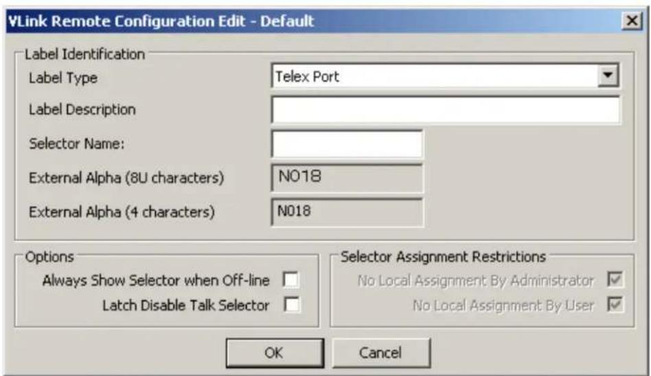
FIGURE 34. Remote Configuration Edit Window
Label Identification Group Box
Label Type Drop Down Menu
The Label Type drop down menu is used to select the type of remote connection. For example, Telex Port for the clients from Telex trunks.
Label Description Field
The Label Description field is used to create additional text to describe the remote connection, such as the city or origin of the remote system.
Selector Name Field
The Selector Name field is used to enter the name seen on the selector.
External Alpha (8U characters) Field
The External Alpha (8U characters) field is used to enter an eight (8) character unicode alpha which is displayed when connected remotely to VLink.
External Alpha (4 characters) Field
The External Alpha (4 characters) field is used to enter a four (4) character alpha which is displayed when connected remotely to VLink.
Options Group Box
Always Show Selector when Off-line Check Box
The Always Show Selector when Off-line check box specifies the selector for this client is visible even if off-line on a Vlink control panel configured to hide offline selectors. Generally, this is used for VLink device interface clients that should never go off-line.
Latch Disable Talk Selector Check Box
The Latch Disable Talk Selector check box indicates the latching state of the talk selector key. When selected, latching is turned off on the talk key.
Selector Assignment Restrictions Group Box
No Local Assignment By Administrator Check Box
The No Local Assignment By Administrator check box indicates this client cannot be assigned locally by the administrator.
No Local Assignment By User Check Box
The No local Assignment By User check box indicates this user cannot assign themselves locally to the system.
OK Button
The OK button accepts the modifications and closes the window.
Cancel Button
The Cancel button rejects the modifications made and closes the window.
System Identification Window
The System Identification window, shown in Figure 35, is used to retrieve the system identification code and to upload a new or modified license file.

FIGURE 35. System Identification Code Window
Information Group Box
The Information group box displays the definition of the system identification code.
System Identification Code Field
The System Identification Code field displays the system identification code given to you.
Upload License File Button
The Upload License File button is used to upload license files to the system.
To upload a license file, do the following:
- Click Upload License File.
The VLink folder, which stores the application information, appears. - Navigate to the folder that holds the license file.
- Select the license file you want to upload.
- Click Open.
The license file is uploaded to the system.
Close Button
The Close button is used to close the System Identification Code window.
System Settings Window
The System Settings window, shown in Figure 36, is used to configure the system administration logon information, server settings, and audio settings.

FIGURE 36. System Settings Window
Master System Administrator Login Group Box
Login Name Field
The Login Name field is used to enter the master administrator's login name.
This field can contain up to 20 characters.
Login Password Field
The Login Password field is used to enter the master administrator's password.
This field can contain up to 20 characters.
Primary Server Network Settings Group Box
The Primary Server Network Settings group box is used to configure the IP Address or SIP information for the primary server used to run the application.
Server IP Address Field
The Server IP Address field is used to enter the IP Address of the server where the application is run from.
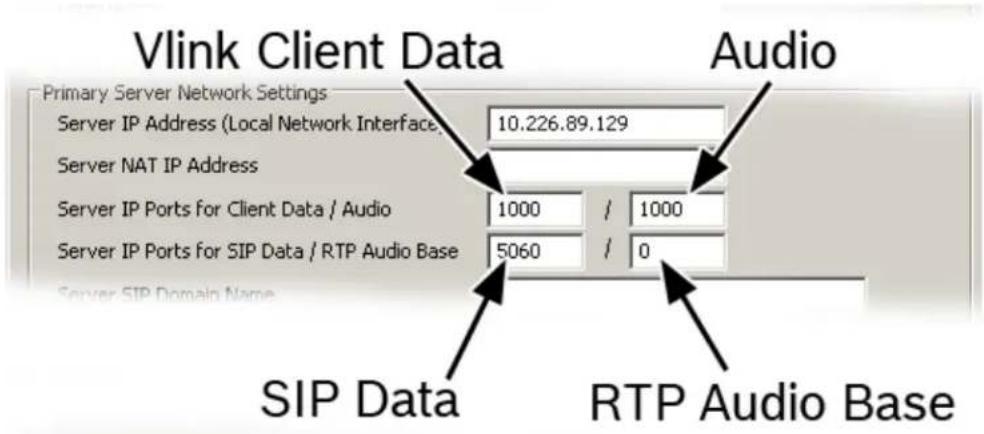
FIGURE 37. VLink Client Data, Audio, SIP Data, RTP Audio Base fields
Server IP Ports for VLink Client Data Field
The Server IP Ports for VLink Client Data field is used to control the TCP/IP port that all client side control panels and device interfaces use to transport data to the virtual matrix. If the virtual matrix is behind a firewall and external access is required, a port forwarding entry must be added to route all traffic on this port to the internal virtual matrix IP Address.
The default for this field is port 1000.
Server IP Ports for VLink Client Audio Field
The Server IP Ports for VLink Client Audio field is used to control the UDP port that all client side control panels and device interfaces use to transport audio to the virtual matrix. The system has no restriction other than reserved ports. If the virtual matrix is behind a firewall and external access is required, a port forwarding entry must be added to route all traffic on this port to the internal virtual matrix IP Address.
The default for this field is port 1000.
Server IP Ports for SIP Data Field
The Server IP Ports for SIP Data field is used to define the IP Port for the integrated SIP server. In general, this value never changes because it is an industry standard port number; however, the value must be changed if multiple VLink virtual matrix instances are to be run on the same physical computer.
The default for this field is 5060.
Server IP Ports for RTP Audio Base Field
The Server IP Ports for RTP Audio Base field is used to establish the IP port number. When set to zero (0), all SIP RTP session establish the IP Port randomly in the range of 10000–42767. In many situations this is adequate, however, if the audio must travel through a firewall, it is not practical or safe to open such a large range of addresses. By specifying an RTP audio base port, the system assigns IP ports sequentially upward from the assigned base port. Once an IP port is assigned to a SIP client, it never changes unless the base port changes.
Server SIP Domain Name Field
The Server SIP Domain Name field is used to define the optional SIP domain for the integrated SIP server. If the SIP domain is specified, it can be used as the SIP proxy name and the registrar name when configuring SIP clients. Whether or not the SIP domain is specified, the virtual matrix IP Address can always be used as the proxy name and the registrar name.
Secondary (Failover) Server Network Settings Group Box
The Secondary (Failover) Server Network Settings group box is used to configure the IP Address or SIP information for the secondary server used to run the application if the primary server has a failure.
Server IP Address Field
The Server IP Address field is used to enter the secondary server IP Address.
Server IP Ports for VLink Client Data Field
The Server IP Ports for VLink Client Data field is used to control the TCP/IP port that all client side control panels and device interfaces use to transport data to the virtual matrix. If the Virtual Matrix is behind a firewall and external access is required, a port forwarding entry must be added to route all traffic on this port to the internal virtual matrix IP Address.
The default for this field is port 1000.
Server IP Ports for VLink Client Audio Field
The Server IP Ports for VLink Client Audio field is used to control the UDP port that all client side control panels and device interfaces use to transport audio to the virtual matrix. The system has no restriction other than reserved ports. If the virtual matrix is behind a firewall and external access is required, a port forwarding entry must be added to route all traffic on this port to the internal virtual matrix IP Address.
The default for this field is port 1000.
Server IP Port for Failover Data Field
The Server IP Port for Failover Data field is used to configure the port used for the two (2) virtual matrix servers to communicate with each other.
Audio Settings Group Box
Audio Mix Sample Rate Drop Down Menu
The Audio Mix Sample Rate drop down menu is used to assign the sampling rate for the audio being passed. The higher the sample rate is, the better quality audio you have. However, higher sample rates equate to more network usage.
Available options for this field are:
Narrowband (8KHz)
Wideband (16KHz)
Ultra Wideband (32KHz)
The default for this field is Ultra Wideband (32KHz).
Audio Output Level Gain (Post-Mix) Field and Slider
The Output Level Gain (Post-Mix) field and slider is used to set the output level gain for the audio being sent in the system.
Available options for this field are:
0 dB
6dB
12dB
18dB
The default for this field is 6dB.
Voice Activity Indication Group Box
Voice Activity Indication Color Text Button
The Voice Activity Indication Color Text button is used to assign a color to the button text when audio is detected. When the button is clicked, a color palette window appears. From this window, choose the color you want to display when audio is detected.
Voice Activity Indication Color Background Button
The Voice Activity Indication Color Background button is used to assign a color to the button background when audio is detected. When the button is clicked, a color palette window appears. From this window, choose the color you want the background to display when audio is detected.
OK Button
The OK button accepts the modifications and closes the window.
Cancel Button
The Cancel button rejects the modifications made and closes the window.
Bosch Security Systems, Inc. System Administration Guide F.01U.217.816 Rev 03
Client Configuration Window
The Client Configuration window, shown in Figure 38, is used to add, edit, and delete VLink clients. The upper portion of the client configuration window displays all configured users and device, login names, passwords, selector labels, client types, and if the given channel is set to party line. There are three (3) types of clients available:
• Control panel clients
• Device interface clients
- SIP clients
To access the Client Configuration window, do the following:
On the System Administration window, click Client Configuration. The VLink Client Configuration window appears.

FIGURE 38. Client Configuration Window
Client List Group Box
The Client List group box displays a list of all the clients in the system.
Client Type Column
The Client Type column displays the client type. For more information, see “Client Configuration Add/Edit Window” on page 27.
Talk/Listen Name Column
The Talk/Listen Name column displays the name assigned to the client for talk/listen operation.
Listen Only Name Column
The Listen Only Name column displays the name assigned to the client for listen only operation.
Login Name Column
The Login Name column displays the login name for the client.
Login Password Column
The Login Password column displays the login password for the client.
Description Column
The Description column displays the description assigned to the client.
Latchable Column
The Latchable column displays the latching state of the client.
Ext Alpha (8U) Column
The Ext Alpha (8U) column displays the eight (8) character unicode external alpha, if applicable.
Ext Alpha (4) Column
The Ext Alpha (4) column displays the four (4) character external alpha, if applicable.
Restrict Column
The Restrict column displays if the client has any selector assignment restrictions.
Port Column
The Port column displays the port number of the client.
Add Button
The Add button is used to open the Add/Edit Client Window. For more information, see "VLink Group Configuration Add/Edit Window" on page 45.
Edit Button
The Edit button is used to open the Add/Edit Client Window. For more information, see "VLink Group Configuration Add/Edit Window" on page 45.
Delete Button
The Delete button is used to remove a client from the system. When clicked, a confirmation message appears.

FIGURE 39. Client Deletion Confirmation Message
Selected Client Group Box
The Selected Client group box becomes active only when a client from the client list is selected. Otherwise, these buttons stay inactive.
Selector Assignments... Button
The Selector Assignments... button is used to open the Client Configuration Selector Assignments window. For more information, see “VLink Client Configuration Selector Assignments Window” on page 30.
Audio Settings... Button
The Audio Settings... button is used to open the Configuration Audio Settings window. For more information, see “VLink Client Configuration Audio Settings Window” on page 34.
Options... Button
The Options button is used to open the Configuration Options window. For more information, see "VLink Client Configuration Options Window" on page 39.
All Clients Group Box
The All Client group box becomes inactive only when a client from the client list is selected. Otherwise, these buttons stay active.
Default Selector Assignments... Button
The Default Selector Assignments... button is used to open the Client Configuration Selector Assignments window.
Default Audio Settings... Button
The Default Audio Settings... button is used to open the Client Configuration Audio Settings window.
Default Options... Button
The Default Options... button is used to open the Client Configuration Options window.
Client Configuration Add/Edit Window
The VLink Client Configuration Add/Edit window, shown in Figure 40, is used to add and/or edit client types. From this window you can create a client type and configure some basic client operations.

FIGURE 40. Client Configuration Add/Edit Window
Client Type Drop Down Menu
The Client Type drop down menu is used to select the type of client you want to create.
Available options for this menu are:
• VLink Control Panel: Desktop
• VLink Device Interface: Four-Wire Interface
• VLink Device Interface: Telephone Interface
• VLink Device Interface: 2-Way Radio Interface
• VDI: Telex Trunk
- SIP Device: Analog Telephony Adapter (FXS)
• SIP Device: PSTN Telephone Interface (FXO)
- SIP Device: Softphone
• SIP Device: Hardphone/IP Phone
Client Description Field
The Client Description field is used to enter a description of the created client. For example the client type may be a hard phone, and the description may be Standard VOIP Hardphone.
This field can contain up to 50 characters.
Login Name Field
The Login Name field is used to enter the name of the client. For example, JackM.
This field can contain up to 20 characters.
Allow Anonymous Login Check Box
The Allow Anonymous Login check box allows a user to login a control panel by entering any login name they choose, followed by the designated password. The chosen login name appears on the selector.
Login Password Field
The Login Password field is used to enter a password for the client you are creating.
This field can contain up to 20 characters.
Selector Talk/Listen Name: Field
The Selector Talk/Listen Name: field is used to enter a display name that is seen above the talk/listen key in the display.
NOTE: Selector is the reference name for keypanel keys or buttons.
This field can contain up to 20 characters.
Selector Listen Only Name Field
The Selector Listen Only Name: field is generally only assigned when a client has a split functionality for the audio input and output as with a program feed input and IFB output.
NOTE: Selector is the reference name for keypanel keys or buttons.
This field can contain up to 20 characters.
External Alpha (8U Characters) Field
The External Alpha (8U Characters) field is used to enter an eight (8) character unicode alpha which is displayed when connected remotely to VLink.
External Alpha (4 Characters) Field
The External Alpha (4 Characters) field is used to enter an four (4) character alpha which is displayed when connected remotely to VLink.
Options Group Box
Always Show Selector when Off-line Check Box
The Always Show Selector when Off-line check box specifies the selector for this client is visible even if offline on a VLink control panel configured to hide off-line selectors. Generally, this is used for VLink device interface clients that should never go off-line.
Latch Disable Talk Selector Check Box
The Latch Disable Talk Selector check box indicates the latching state of the talk selector key. When selected, latching is turned off on the talk key.
Party Line Operation Check Box
The Party Line Operation check box indicates a given client operates as a party line. This means that anyone talking to the client also talks to anyone listening to that client; and anyone listening to that client hears everyone talking to that client.
IFB Destination Check Box
The IFB Destination check box designates a client as an IFB destination. This causes the system to interrupt any assigned listen or program feeds to the destination when a control panel initiates a talk path to the destination. Typically, this setting is used with on-air talent who need to be constantly monitoring the on-air program feed, but take cues from the director or producer.
ISO Destination Check Box
The ISO Destination check box designates a client as an ISO destination which causes the system to interrupt any assigned listen or program feeds to the destination when a control panel initiates a talk path to the destination and automatically activates a return talk path from the destination back to the control panel. Additionally, the talk paths in both directions are isolated so conversations are kept private. Typically, this setting is used with cameras when the director or producer needs to isolate a particular camera from the camera PL (Party Line) to provide private instruction.
Selector Assignment Restrictions Group Box
No Local Assignment By Administrator Check Box
The No Local Assignment By Administrator check box indicates this client cannot be assigned locally by the administrator.
No Local Assignment By User Check Box
The No Local Assignment By User check box indicates this user cannot assign themselves locally to the system.
No Remote Assignment By Administrator Check Box
The No Remote Assignment By Administrator check box indicates this client cannot be assigned remotely by the administrator.
No Remote Assignment By User Check Box
The No Remote Assignment By User check box indicates this user cannot assign themselves remotely to the system.
OK Button
The OK button accepts the modifications and closes the window.
Cancel Button
The Cancel button rejects the modifications made and closes the window.
VLink Client Configuration Selector Assignments Window
The VLink Client Configuration Selector Assignments window, shown in Figure 41, is used to assign users/clients to available selectors in the system and, once assigned, allows you to assign operations the client is permitted to use.
NOTE: Selector is the reference name for keypanel keys or buttons.

FIGURE 41. VLink Client Configuration Selector Assignments Window
Selected Client Group Box
The Selected Client group box displays the type of client being displayed. The information in this field is directly related to the selection or non-selection of a specific client.
Available options for this field are: Default Settings for all Clients or the Name of the selected client.
Non-Assigned Selectors Group Box
The Non-Assigned Selectors group box displays a list of selectors that have not yet been assigned in the system.
Label Type Column
The Label Type column displays the label type of the non-assigned selector.
Name Column
The Name column displays the name of the non-assigned selector.
Description Column
The Description column displays the description of the client.
Selector Configuration Buttons
--> Split Talk/Listen --> Button
The ---> Split Talk/Listen ---> button is used to move a non-assigned selector to the assigned selector column with a split talk/listen button assignment.
----> Talk Only ----> Button
The ---> Talk Only ---> button is used to move a non-assigned selector to the assigned selector column with a talk only button assignment.
---->Listen Only ---->Button
The ---> Listen Only ---> button is used to move a non-assigned selector to the assigned selector column with a listen only button assignment.
Remove <---- Button
The <---- Remove button is used to move an assigned selector to the non-assigned selector list.
Clear ----> Button
The Clear ----> button is used to remove any additional capabilities that were added to the selector.
Latchable ---> Button
The Latchable ---> button is used to add the ability to latch to the selected selector assignment.
IFB ----> Button
The IFB ----> button is used to add the ability to be an IFB destination to the selected selector assignment.
ISO---->Button
The ISO ----> button is used to add the ability to be an ISO to the selected selector assignment.
Speaker Dim -> Button
The Speaker Dim -> button is used to add the speaker dim setting to the client selector settings.
Hot Key ----> Button
The Hot Key ----> button is used to define a keyboard shortcut to activate or deactivate the selector on a control panel. When clicked, the Selector Hot Key window appears. From this window, you can define what keyboard actions are used for the shortcut (i.e., Ctrl+Alt+Space Bar). For more information, see “Selector Hot Key Window” on page 33.
Assigned Selectors Group Box
Name Column
The Name column displays the name of the selector.
Selector Type Column
The Selector Type column displays the selector type. There are three (3) selector types available.
Available options for this field are: Split Talk/Listen, Talk Only, and Listen Only.
Selectors to Display per Row Field
The Selectors to Display per Row field designates the number of selectors that can be displayed per row in the control panel.
Selector Activation Method Drop Down Menu
The Selector Activation Method drop down menu is used to select under what circumstances the assigned selectors become active.
Available options are:
| On This Client Connect - | This is the default option. This option results in the selectors be activated as long as the client is connected. |
| On Other Client Disconnect - | This option results in the selectors being activated only when a specific client as designated by the Selector Activation Detail is disconnected allowing for a redundant audio input of a critical feed. |
| On Voice Activity Detection - | This option results in the selectors being activated only when voice activity is detected allowing for a device like a 2-way radio to provide In-Use indication when the channel is active. |
| On Logic Input Activation - | This option results in the selectors being activated only when an external logic input signal is detected via the device interface application. This allows for a device like a 2-way radio to provide in-use indications when the channel is active. |
| On DTMF Tone Detection - | This option, available only for SIP clients, results in the selectors being activated only when the selector's corresponding DTMF code is detected. The corresponding DTMF codes are the order in which the selectors appear in the list from one (1) to the number of selectors. A DTMF code of zero (0) turns off any previously activated selector. |
Selector Activation Detail Field
The Selector Activation Detail field displays the activation method selected. This is applicable only to non-client devices (i.e., 4-wire input/output, SIP, etc).
OK Button
The OK button accepts the modifications and closes the window.
Cancel Button
The Cancel button rejects the modifications made and closes the window.
Selector Hot Key Window
The Selector Hot Key window, shown in Figure 42, is used to configure a hot key for the application. A hot key is also known as a keyboard shortcut and used similarly.

FIGURE 42. Selector Hot Key Window
Hot Key Group Box
Alt Check Box
The Alt check box is used to indicate the Alt key is used in the hot key operation.
Control Check Box
The Control check box is used to indicate the Ctrl key is used in the hot key operation.
Shift Check Box
The Shift check box is used to indicate the Shift key is used in the hot key operation.
Key Drop Down Menu
The Key drop down menu is used to define a key to be used in conjunction with the Alt, Ctrl, and/or Shift keys in the hot key operation.
Available options for this field are: Space, Page Up, Page Down, End, Home, Left, Up, Right, Down, Select, Print, Execute, Snap Shot, Insert, Delete, Help, 0-9 (top row numbers), A-Z, Sleep, 1-9, *,+,-, (comma), . (period), /, F1-F24, Browser Back, Browser Forward, Browser Refresh, Browser Stop, Browser Search, Browser Favorites, Browser Home, Volume Mute, Volume Up, Next Track, Prev Track, Stop Media, Play/Pause Media, Launch Mail, Launch Media, Launch App 1, and Launch App 2.
Clear Button
The Clear button is used to clear the hot key configurations made.
OK Button
The OK button accepts the modifications and closes the window.
Cancel Button
The Cancel button rejects the modifications made and closes the window.
VLink Client Configuration Audio Settings Window
The VLink Client Configuration Audio Settings window, shown in Figure 43, is used to configure the audio heard in the system.

FIGURE 43. VLink Client Configuration Audio Settings
Selected Client Group Box
The Selected Client group box displays the type of client being displayed. The information in this field is directly related to the selection or non-selection of a specific client.
Available options for this field are: Default Settings for all Clients or the Name of the selected client.
Audio Quality Group Box
Audio Encoder/Decoder Drop Down Menu
The Audio Encoder/Decoder drop down menu is used to select a different encoder/decoder
Available selections for VLink control panels and device interfaces:
High Compression/Low Bitrate Codec (Default, Used for Internet connectivity)
Low Compression/Hi Bitrate Codec (Used for local network connectivity to slightly reduce latency)
Available selections for SIP clients:
Preferential Codec used when negotiating which codec to use with the SIP device.
Audio Encoder Sample Rate Drop Down Menu
The Audio Encoder Sample Rate drop down menu is used to control the sampling rate supported by the clients and dictates the default fidelity for the client connections. This setting is typically the same as the system audio sampling rate, however it can be set at a lower rate but never at a higher rate.
NOTE: Higher audio sampling rates have more significant requirements both in computational speed and network bandwidth, so careful consideration must be made when choosing this setting with respect to client hardware and the client network connection.
Available selections for this field are:
Ultra Wideband (32KHz) Default
Wideband (16KHz)
Narrowband (8KHz)
TABLE 2. Bandwidth Utilization
| Audio Sample Rate | Data Rate (Kbps) [ATS a =20ms] | Data Rate (Kbps) [ATS a =40ms] | Data Rate (Kbps) [ATS a =60ms] | Data Rate (Kbps) [ATS a =80ms] | Data Rate (Kbps) [ATS a =100ms] | ||||
| 8KHz | 32 | 23.6 | 20.8 | 19.4 | 18.56 | ||||
| 16KHz | 44.8 | 36.4 | 33.6 | 32.2 | 31.36 | ||||
| 32KHz 46. | 8 | 38.4 | 35.6 | 34.2 | 33.36 | ||||
a. ATS (Audio Time Slice) per packet controls how many 20ms audio frames are transmitted within a single UDP packet. As each UDP packet requires a fixed amount of overhead, the more frames sent at the same time, the less the UDP overhead is used, which conserves network bandwidth. Conversely, the more audio frames sent per transmission, the greater the system latency and the potential audible consequence of a lost packet. The default is 20ms.
Audio Encode Quality Field and Slider
The Audio Encode Quality field and slider are used to set the compression rate for the audio. The higher the compression is, the lower the quality of the input speech signal. Unlike some other speech codecs, it is possible to control the trade-off made between quality and bit rate.
Available options for this field are: -8, -7, -6, -5, -4, -3, -2, -1, Standard, +1, and +2.
Audio Encode Complexity Field and Slider
The Audio Encode Complexity field and slider is used to elevate the audio complexity level to achieve superior results when encoding non-speech sounds, like DTMF tone.
Available options for this field are: 1, Standard, +1, +2, +3, +4, +5, +6, +7, and +8.
Variable Bit Rate Check Box
The Variable Bit Rate check box indicates the system's codec is allowed to dynamically change the bit rate at which audio is being encoded. Sounds, like vowels, require a higher bit rate to achieve good quality as compared to "s" and "f" sounds, this setting achieves the best sound quality within the given confines. The system can be set for variable rate or fixed rate. While this setting improves the quality of speech, it conversely degrades the quality of music and should therefore be disabled when using a program feed.
Audio Transmission Group Box
Audio Capture Buffer Size Field and Slider
The Audio Capture Buffer Size field and slider are used to control the size of the audio capture buffer used by the VLink control panel and VLink device interface when using the Microsoft WDM drivers. With some slower computers and/or handhelds, the audio capture buffer size may need to be increased in order to prevent audio overrun issues.
NOTE: Increasing this value also increases the audio latency.
Available options for this field are: 20ms, 40ms, 60ms, 80ms, 100ms, 120ms, 140ms, 160ms, 180ms, and 200ms. The default value for this field is 20ms.
Audio Time Slice Per Packet Field and Slider
The Audio Time Slice Per Packet field and slider is used to control how may 20ms audio frames are transmitted within a single UDP packet. As each UDP packet represents a fixed amount of overhead, the more frames sent at the same time the less UDP overhead which conserves network bandwidth. Conversely, the more frames sent per transmission, the greater the system latency and audible consequence of lost packets, e.g. 20ms of lost frames is hardly audible, where 40ms is.
Available options for this field are: 20ms, 40ms, 60ms, 80ms, and 100ms. The default for this field is 20ms.
Jitter Buffer Size Field and Slider
The Jitter Buffer Size field and slider is used to specify the depth of the jitter buffer in milliseconds. In network-based communications, the delivery time of audio packets across the network may not be uniform. This characteristic is known as jitter. As such, audio received from a network connection must be buffered to compensate for this such that a continuous time-relative stream of audio can be delivered to the user of the audio. Different network topologies have different jitter characteristics, for example, a public Internet connection, will have significantly more jitter than an internal local network. The effect of a jitter buffer that is set too small, results in audio gaps. The value is specified in milliseconds.
Available options for this field are: 20ms, 40ms, 60ms, 80ms, 100ms, 120ms, 140ms, 160ms, 180ms, and 200ms. The default for this field is 20ms.
Silence Suppression Time Field and Slider
The Silence Suppression Time field and slider are used to cease all transmission of audio data when no voice activity is detected from a control panel or device interface after the specified time lapse. This eliminates most background noise during multi-party conferences; however, it may be initially disconcerting to some individuals as the comfort noise typically associated with analog systems is suppressed. Additionally, this feature minimizes the overall required network bandwidth. The value is specified in milliseconds in the range of 100–1000ms, or can be turned off completely.
Available options for this field are: Off, 100ms, 200ms, 300ms, 400ms, 500ms, 600ms, 700ms, 800ms, 900ms, and 1000ms. The default for this field is 1000ms.
Packet Resequencer Depth Field and Slider
The Packet Resequencer Depth field and slider is used to specify the number of packets that are stored when waiting for an out of sequence audio packet. In some network topologies, UDP packets are sent in sequential order are received non-sequentially. As such, these packets must be re-sequenced before use. After the maximum re-sequencer depth has been reached, the packet being waited for is declared to be lost and the re-sequencing is restarted at the next earliest received packet.
Available options for this field are: 1 packet, 2, packets, 3 packets, 4 packets, 5 packets, 6 packets, 7 packets, 8 packets, 9 packets, and 10 packets.
The default for this field is 6 packets.
Audio Levels Group Box
Automatic Gain Control Check Box
The Automatic Gain Control check box enables or disables AGC (Automatic Gain Control) on the audio path from client to the server. AGC automatically increases or decreases the audio level that the client presents a uniform audio level to the virtual matrix. AGC is primarily appropriate for use with a control panel when used with a headset microphone. In some situations, where there is a high amount of background noise or some return audio leakage, the AGC may incorrectly amplify the noise to normal audio levels.
Automatic Gain Control Level Field and Slider
The Automatic Gain Control Level field and slider is used to increase or decrease the sensitivity of the AGC. Increasing or decreasing the sensitivity of the AGC, changes the behavior of the AGC that it adapts faster or slower to audio levels not considered to be at uniform level. Decreasing the sensitivity may be useful in cases where there is a high amount of background noise or some return audio leakage.
Available options for this field are: -8, -7, -6, -5, -4, -3, -2, -1, Standard, +1, +2, +3, +4, +5, +6, +7, +8, +9, +10, +11, +12, +13, +14, +15, +16, +17, +18, +19, +20, +21, +22, and +23.
The default for this field is Standard.
Audio Input Level Gain (Pre-Mix) Field and Slider
The Audio Input Level Gain (Pre-Mix) field and slider is used to control the audio input level sent from the client to the virtual matrix. This setting is typically used only when the client's audio input device does not provide a sufficiently audible level (as heard by all other clients) and does not have a local gain control to compensate. The value can be adjusted a maximum of ±18dB in 6dB increments.
Available options for this field are: -18dB, -12dB, -6dB, 0dB, +6dB, +12dB, and +18dB. The default for this field is 0dB.
Audio Output Level Gain (Post-Mix) Field and Slider
The Audio Output Level Gain (Post-Mix) field and slider is used to control the audio output level sent to the client from the virtual matrix. This setting is typically used only when the client's audio output device does not provide a sufficiently audible level and does not have a local gain control to compensate. The value can be adjusted a maximum ±18dB in 6dB increments.
Available options for this field are: -18dB, -12dB, -6dB, 0dB, +6dB, +12dB, and +18dB. The default for this field is 0dB.
Speakerphone Speaker Dim Reduction Field and Slider
The Speakerphone Speaker Dim Reduction field and slider are used to adjust the audio level of the speaker phone by lowering the Dim level.
Available options for this field are: None, -6dB, -12dB, -18dB, -24dB, -30dB, -36dB, and Mute. The default for this field is -12dB.
Audio Processing Group Box
Echo Cancellation Check Box
The Echo Cancellation check box is used to enable or disable the client's echo cancellation. Echo cancellation is useful if there is any return audio leakage from the client's speaker back to their microphone, as this may result in an audible echo heard by any other client that is talking and listening to the client with the return audio leakage.
Echo Cancellation Tail Length Field and Slider
The Echo Cancellation Tail Length field and slider is used to control the duration the echo canceller waits to received the echo before it begins the cancellation process. The recommended tail length is approximately a third of the room reverberation time. For example, in a small room, reverberation time is approximately 300ms. A tail length of 100ms is recommended.
Available options for this field are: 50ms, 100ms, 150ms, 200ms, 250ms, and 300ms. The default for this field is 100ms.
OK Button
The OK button accepts the modifications and closes the window.
Cancel Button
The Cancel button rejects the modifications made and closes the window.
VLink Client Configuration Options Window
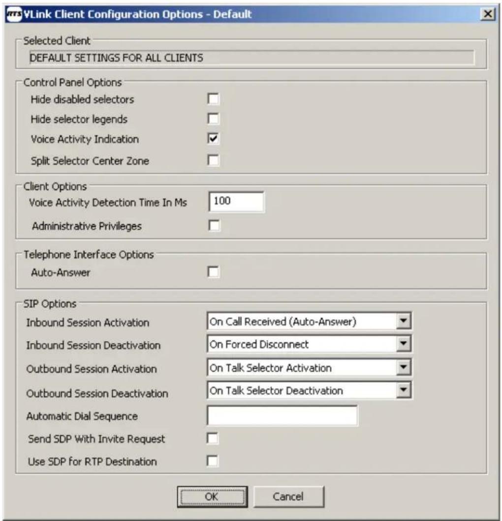
FIGURE 44. VLink Client Configuration Options Window
Selected Client Group Box
The Selected Client group box displays the type of client being displayed. The information in this field is directly related to the selection or non-selection of a specific client.
Available options for this field are: Default Settings for all Clients or the Name of the selected client.
Control Panel Options
Hide Disabled Selectors Check Box
The Hide Disabled Selectors check box is used to hide selectors assigned to other clients not logged into the system. When the clients come online, their selector dynamically becomes active.
Hide Selector Legends Check Box
The Hide Selector Legends check box is used to hide the overlaid selector legends displayed on the listen selectors (L) and talk selectors (T).

FIGURE 45. Selector Legends
Voice Activity Indication Check Box
The Voice Activity Indication check box is used to visually indicate voice activity on control panel selectors, represented by selector text and background color switching between base state (yellow text/navy background) and default activity indication colors (white text/light navy background) or selected activity indication colors (variable). Voice activity indication is only available if the control panel has the ability to listen to or is being talked to by the client indicating voice activity.
Split Selector Center Zone Check Box
The Split Selector Center Zone check box is used to configure a split talk/listen key. When selected, it allows the user to select the center of the key to turn on both functions at the same time.
Client Options Group Box
Voice Activity Detection Time in Ms Field
The Voice Activity Detection Time in Ms field is used to determine the duration in milliseconds after which a voice or sound is valid for indication.
Administration Privileges Check Box
The Administration Privileges check box is used to give administrative privileges to the selected users when logging in to the System Administration application with their assigned user name and password.
Telephone Interface Options Group Box
Auto-Answer Check Box
The Auto-Answer check box is used to enable the system to automatically answer an incoming telephone call.
SIP Options Group Box
Inbound Session Activation Drop Down Menu
The Inbound Session Activation drop down menu is used to select how the virtual matrix handles the activation of a call initiated by the SIP client.
Available options for this field are:
- If configured for disabled, the call initialized by the SIP client is ignored.
- If configured for On Call Received (Auto-Answer), the call initiated by the SIP client is automatically answered by the virtual matrix.
- If configured for On Talk Selector Activation, the call initiated by the SIP client is answered only if a control panel activates the talk selector associated with the SIP client.
Inbound Session Deactivation Drop Down Menu
The Inbound Session Deactivation drop down menu is used to select how the virtual matrix handles the deactivation of a call initiated by the SIP client.
Available options for this field are:
- If configured for Disabled, the call initiated by the SIP client can never be disconnected by the virtual matrix.
- If configured for On Forced Disconnect, the call initiated by the SIP client can only be disconnected by the control panel using the disable client login feature.
- If configured for On Talk Selector Deactivation, the call initiated by the SIP client disconnects when all control panels deactivate the talk selectors associated with the SIP client.
Outbound Session Activation Drop Down Menu
The Outbound Session Activation drop down menu is used to select how the virtual matrix handles the activation of a call initiated to the SIP client.
Available options for this field are:
- If configured for Disabled, the virtual matrix cannot initiate any call to the SIP client.
- If configured for On Registration, the virtual matrix initiates a call to the SIP client as soon as the SIP client makes its presence known through a process know as Registration.
- If configured for On Talk Selector Activation, the virtual matrix initiates a call to the SIP client when any control panel activates the talk selector associated with the SIP client.
Outbound Session Deactivation Drop Down Menu
The Outbound Session Deactivation drop down menu is used to select how the virtual matrix handles the deactivation of a call initiated to the SIP client.
Available options for this field are:
- If configured for Disabled, the call initiated to the SIP client can never be disconnected by the virtual matrix.
- If configured for On Forced Disconnect, the call initiated to the SIP client can only be disconnected by a control panel using the Disable Client Login feature.
- If configured for On Talk Selector Deactivation, the call initiated to the SIP client disconnects when all control panels deactivate the talk selectors associated with the DIP client.
Automatic Dial Sequence Field
The Automatic Dial Sequence field is used to specify a dial sequence to be dialed as soon as a call is established with a SIP client.
To insert a delay in the dial sequence, do the following:
In the Automatic Dial Sequence field, enter P to insert a five (5) second delay. OR
In the Automatic Dial Sequence field, enter p to insert a one (1) second delay.
Send SDP With Invite Request Check Box
The Send SDP With Invite Request check box is used to change the default behavior of call initiated by the virtual matrix to allow compatibility with devices that do not conform to proper SIP implementation. Normally when the virtual matrix initiates a call to the SIP client, it does so without sending a SDP (Session Description Protocol) so that it can subsequently control the codec selection.
Use SDP for RTP Destination Check Box
The Use SDP for RTP Destination check box is used to change the default behavior of the virtual matrix to allow strict conformance with the RTP (Real-Time Protocol) specification. Normally, the virtual matrix ignores the RTP IP Address specified in the SDP and uses the actual received RTP IP Address as the SIP specification as written does not account for SIP clients behind NAT firewalls.
OK Button
The OK button accepts the modifications and closes the window.
Cancel Button
The Cancel button rejects the modifications made and closes the window.
VLink Group Configuration Window
The Group Configuration window, shown in Figure 46, is used to add, edit, and delete party lines and fixed groups, change selector names, and change group memberships.

FIGURE 46. VLink Group Configuration Window
Group List Group Box
Group Type Column
The Group Type column displays the types of group types currently existing in the system.
Talk/Listen Name Column
The Talk/Listen Name column displays the name assigned to the talk/listen assignment.
Description Column
The Description column displays a description of the Group, if available.
Latchable Column
The Latchable column displays the status of latching for that group. No displays if latching is disabled, Yes displays if latching is enabled.
Ext Alpha (8U) Column
The Ext Alpha (8U) column displays the eight (8) character unicode external alpha, if applicable.
Ext Alpha (4)Column
The Ext Alpha (4) column displays the four (4) character external alpha, if applicable.
Restrict Column
The Restrict column displays if the client has any selector assignment restrictions.
Port Column
The Port column displays the port number the group is assigned.
Add Button
The Add button is used to open the VLink Group Configuration Add/Edit window. For more information, see “VLink Group Configuration Add/Edit Window” on page 45.
Edit Button
The Edit button is used to open the VLink Group Configuration Add/Edit window. For more information, see “VLink Group Configuration Add/Edit Window” on page 45.
Delete Button
The Delete button is used to remove a group from the group list. When the Delete button is clicked, a warning message appears confirming the deletion.

FIGURE 47. Group Deletion Confirmation
Selected Group Group Box
Group Membership Button
The Group Membership button is used to open the VLink Group Configuration Membership window. For more information, see “VLink Group Configuration Membership Window” on page 47.
VLink Group Configuration Add/Edit Window
The Group Configuration Add/Edit window, shown in Figure 48, is used to create or edit a group in the system.

FIGURE 48. VLink Group Configuration Add/Edit Window
Type Drop Down Menu
The Type drop down menu is used to select what type of group you want to create.
Available options for this field are:
Party Line - the group is configured for party line operation.
Fixed Line - the group is configured for fixed line or special list operation.
Description Field
The Description field is used to enter a description of the group you create.
This field can contain up to 50 characters.
Selector Talk Label Field
The Selector Talk Label field is used to assign a name that is seen on the selector in the software.
This field can contain up to 20 characters.
External Alpha (8U Characters) Field
The External Alpha (8U Characters) field is used to enter an eight (8) character unicode alpha which is displayed when connected remotely to VLink.
External Alpha (4 Characters) Field
The External Alpha (4 Characters) field is used to enter a four (4) character alpha which is displayed when connected remotely to VLink.
Options Group Box
Latch Disabled Check Box
The Latch Disabled check box is used to enable or disable latching for the group configuration. If selected, latching is not active.
Selector Assignment Restrictions Group Box
No Local Assignment By Administrator Check Box
The No Local Assignment By Administrator check box indicates this client cannot be assigned locally by the administrator.
No Local Assignment By User Check Box
The No Local Assignment By User check box indicates this user cannot assign themselves locally to the system.
No Remote Assignment By Administrator Check Box
The No Remote Assignment By Administrator check box indicates this client cannot be assigned remotely by the administrator.
No Remote Assignment By User Check Box
The No Remote Assignment By User check box indicates this user cannot assign themselves remotely to the system.
VLink Group Configuration Membership Window
![VLink Group Configuration Membership - Default Selected Group Studio to Truck TDIR PL Non-Group Members Client Type Name Description VDI: Four-Wire Interface [CBS-IO10] CBS Tie Line #10 VDI: Four-Wire Interface [CBS-IO11] CBS Tie Line #11 VDI: Four-Wire Interface [CBS-IO12] CBS Tie Line #12 VDI: Fou…](/content/2026/05/1009266/images/fb132c9f33f45452169f53f1436ddc1be3470cd7c8868cf4c9fe8e0437102d19.jpg)
FIGURE 49. VLink Group Configuration Membership Window
Selected Group Group Box
Non-Group Members Group Box
Client Type Column
The Client Type column displays the client type. For more information, see “Client Configuration Add/Edit Window” on page 27.
Name Column
The Name column displays the name assigned to the client.
Description Column
The Description column displays the description assigned to the client.
--> Talk and Listen --> Button
The Talk and Listen button is used to move a non-assigned selector to the assigned selector column with a talk and listen button.
----> Talk Only ----> Button
The Talk Only button is used to move a non-assigned selector to the assigned selector column with a talk only button.
---->Listen Only ----> Button
The Listen Only button is used to move a non-assigned selector to the assigned selector column with a listen only button.
Remove <---- Button
The Remove button is used to move any assigned select to the non-assigned selector list.
Clear ----> Button
The Clear button is used to remove any additional capabilities that were added to the selector.
Group Members Group Box
Name Column
The Name column displays the name of the group.
Mode Column
The Mode column displays the mode the group is configured for (for example, talk and listen).
OK Button
The OK button accepts the modifications and closes the window.
Cancel Button
The Cancel button rejects the modifications made and closes the window.
VLink Client Statistics Window
| Client | State | Duration | DEC | DSCD | SARAE | SAPLLS | SAPLLM | SAPLSL | RARED | RAPLLS | RAPLLM | RAPLSL | CPU | IP Address | Version |
| ATA #1 | Off-Line | 20m | - | - | - | - | - | - | - | - | - | - | - | ||
| Ext. 1000 | Off-Line | 20m | - | - | - | - | - | - | - | - | - | - | - | ||
| Ir/Out. #1 | Off-Line | 20m | - | - | - | - | - | - | - | - | - | - | - | ||
| Ir/Out. #2 | Off-Line | 20m | - | - | - | - | - | - | - | - | - | - | - | ||
| Ir/Out. #3 | Off-Line | 20m | - | - | - | - | - | - | - | - | - | - | - | ||
| Ir/Out. #4 | Off-Line | 20m | - | - | - | - | - | - | - | - | - | - | - | ||
| Ir/Out. #5 | Off-Line | 20m | - | - | - | - | - | - | - | - | - | - | - | ||
| Ir/Out. #6 | Off-Line | 20m | - | - | - | - | - | - | - | - | - | - | - | ||
| Ir/Out. #7 | Off-Line | 20m | - | - | - | - | - | - | - | - | - | - | - | ||
| Ir/Out. #8 | Off-Line | 20m | - | - | - | - | - | - | - | - | - | - | - | ||
| Ir/Out. #9 | Off-Line | 20m | - | - | - | - | - | - | - | - | - | - | |||
| Station #1 | Off-Line | 20m | |||||||||||||
FIGURE 50. VLink Client Statistics Window
Client Column
The Client column displays the name of the client.
State Column
The State column displays the state of the client. When a client is active, Online displays. When a client is not online, Off-Line displays.
Duration Column
The Duration column displays the amount of time the user has been active. Times are given in hours (h) and minutes (m)
DEC Column
The DEC (Disconnect Event Column) column displays the number of times the connection has gone down.
DSCD Column
DSCD (Disconnect State Cumulative Duration)
SARAE Column
The SARAE (Send Audio Rate After Encoding (Kbps)) displays the amount of audio data present on transmit.
SAPLLS
The SAPLLS column displays the percentage of send audio packets lost in the last second.
SAPLLS (Send Audio Packet Loss Last Second [%])
SAPLLM Column
The SAPLLM column displays the percentage of send audio packets have been lost in the last minute.
SAPLLM (Send Audio Packet Loss Last Minute [%])
SAPLSL Column
The SAPLSL column displays the percentage of send audio packets lost since logging into the system.
SAPLSL (Send Audio Packet Loss Since Login [%])
RARBD Column
RARBD (Receive Audio Rate Before Decoding (Kbps))
RAPLLS Column
The RAPLLS column displays the percentage of receive audio packets lost in the last second.
RAPLLS (Receive Audio Packet Loss Last Second [%])
RAPLLM Column
The RAPLLM column displays the percentage of receive audio packets lost in the last minute.
RAPLLM (Receive Audio Packet Loss Last Minute [%])
RAPLSL Column
The RAPLSL column displays the percentage of receive audio packets lost since logging into the system.
RAPLSL (Receive Audio Packet Loss Since Login [%])
CPU Column
The CPU column displays the percentage of the CPU (Centralized Processing Unit) the client is using.
IP Address Column
The IP Address column displays the IP Address of the client.
Version Column
The Version column displays the version of the client.
Reset Statistics Button
The Reset Statistics button is used to reset all the values collected for the displayed clients.
Show Unused Clients Check Box
The Show Unused Clients check box is used to display clients not currently active.
Column Legend... Button
The Column Legend... button is used to open a window displaying the full names of the acronyms used in the Client Statistics window.

FIGURE 51. Client Statistics Legend Window
Close Button
The Close button closes the window.
VLink SIP Registrations Window VLink

FIGURE 52. VLink SIP Registrations Window
User Name Column
The User Name column displays the name of the user currently using SIP.
Address of Record Column
The Address of Record column displays the IP Address of the SIP record currently being used.
Contact Detail Column
The Contact Detail column displays the contact information for the SIP registration.
Expiration Time Column
The Expiration Time column displays the time the SIP registration expires.
Close Button
The Close button closes the window.
Activity Log Window
The Activity Log window, shown in Figure 53, is used to see a line item view of all activity that has occurred on the system. Log entries display the date, time, and the event.
![Activity Log Log 05/05/11 14:07:24 - VLink Virtual Matrix version: 2.3.0.207 05/05/11 14:07:26 - [License] Licensed to Telex for 200 clients until 08/31/2011 05/05/11 14:07:26 - Server configuration file: "C:\Program Files\RTS\VLink\SystemConfiguration.txt" ... # of Configured Users: 21, System Audi…](/content/2026/05/1009266/images/8237137dbf7393bf3a3c469a04b2fb0c2c84fea57e60678f378824ca161e9987.jpg)
FIGURE 53. Activity Log Window
Log Group Box
The Log group box displays the events that have occurred on the system.
No Scroll Button
The No Scroll button is used to manually scroll through the activity log. Normally, the activity log dynamically updates, showing the most current activity logged. When the No Scroll button is selected, a right-hand slider appears allowing for you to look through the activity log history.
Close Button
The Close button closes the window.
VLink Device Interface
VLink Device Interface is a software application that bridges VLink with multiple external communications systems.
NOTE: A hardware audio/logic interface is required to convert 4-wire and 2-wire analog signals into digital to bridge with the IP world, typically via USB or Firewire 1 connection. To bridge a telephone system a hybrid is also required or a PC/server card which accepts analog phone lines or T-1(s) directly.
Installation
To install the VLink Device Interface software, do the following:
- Locate the VLink Device Interface setup application (provided either electronically or on the CD).
- Run the installer.
- Follow the prompts.
You must to accept VLink Systems' License Agreement to install the software. - Once installation is complete, select the Launch VLink Device Interface check box.
- Click Finish.
Configuration
When running the VLink Device Interface for the first time, the VLink Device Interface Configuration window automatically appears.
To configure the VLink Device Interface, do the following:
- On the VLink Device Interface window, click Configure.
The Device Interface Configuration Window appears.

- Under Network Settings, enter the Virtual Matrix IP Address and port number (after the colon) supplied by your system administrator. The Device Interface IP Address is your computer's IP address and should already be input; however, some PCs may have multiple connections. Verify the correct address is selected.
- Under Monitor Device, select the secondary audio output device. Typically, an external speaker allows monitoring the audio input and output of the configured devices.
- Under Logic Input/Output, select the GPIOs device (if any) you use to control your audio devices. Optional.
- Click Close to save the configured settings.
To add a device, do the following:
- On the Device List window, click Add.
The VLink Device Configuration Window appears.

- In the Login Name field, enter the login name for the device, as pre-configured in the VLink System Configuration application.
- In the Login Password field, enter the login password for the device, as pre-configured in the VLink System Configuration application.
NOTE: Under Analog to Digital Audio Device, select the audio input and output device.
Typically this a USB 4-wire to digital converter; however any audio input and output device can be used.
- From the Select Input Device drop down menu, locate the correct audio input device.
Often, but not always, the select input connector and the select output device drop down menus automatically populate with the correct setting.
- From the Select Input Connector drop down menu, select the input jack the audio input device is to use.
- From the Select Input Channel drop down menu, select either mono, stereo - left, or stereo - right.
- Using the Set Input Level slider, adjust the input audio level, if applicable.
-
From the Select Output Device drop down menu, locate the correct audio output device.
-
From the Select Output Connector drop down menu, select the output jack the audio output device is to use.
- From the Select Output Channel drop down menu, select either mono, stereo - left, or stereo - right.
- Under Logic Input/Output, select the logic protocol and input(s)/output(s) that you wish to use for the given audio device.
- Click Apply.
The device is added to device interface list.
To edit a device, do the following:
- In the Device list, select a device.
- Click Edit.
The VLink Device Configuration window appears for the specified device.
- Make the modifications you want.
- Click Apply.
To delete a device, do the following:
- In the Device list, select a device.
- Click Delete.
Operation
BASIC FUNCTIONALITY AND FEATURES

FIGURE 54. VLink Device Interface
All Devices Group Box
Login/Logout Button
The Login/Logout button is used to connect or disconnect all configured devices simultaneously.
Selected Device(s) Group Box
Buttons in the section operate only on the selected device in the Device List
Login/Logout Button
The Login/Logout button is used to connect or disconnect the selected device.
Monitor Input Button
The Monitor Input button allows monitoring of the audio being sent from the device to the virtual matrix.
Monitor Output Button
The Monitor Output button allows monitoring of the audio being sent from the virtual matrix to the device.
Simulate GPI(s) Button
The Simulate GPI(s) button is used to demonstrate the effect of activating the configured general purpose inputs and is for testing purposes only.
Toggle GPO(s) Button
The Toggle GPO(s) button forces activation of the configured general purpose outputs and is for testing purposes only.
Statistics Button
The Statistics button displays the send and receive audio rates and packet loss data.
Configure Button
The Configure button opens the VLink Device Interface Configuration window.
Add Button
The Add button opens the VLink Device Configuration window which is used to add a device.
Edit Button
The Edit button opens the VLink Device Configuration window corresponding to the device highlighted in the Device List.
Delete Button
The Delete button deletes the selected device.
TROUBLESHOOTING
Following are answers to the most commonly experienced issues of new users.
Question Answer
When attempting to login to the Virtual Matrix I get a “Cannot connect to Virtual Matrix” message?
The Device Interface is unable to establish a TCP/IP data connection with the Virtual Matrix. Check the Device Interface Configuration to ensure Device Interface IP Address is valid and represents a valid and active network connection. Ensure that the Virtual Matrix IP Address is entered exactly as provided with the designated port number. Check to ensure a corporate firewall is not intentionally blocking the designated TCP/IP data port.
When attempting to login to the Virtual Matrix I get a “Unable to establish return audio path” message?
The Device Interface is unable to establish a UDP audio connection with the Virtual Matrix. Check to ensure a corporate firewall is not intentionally blocking the designated UDP audio port which is typically the same as the TCP/IP data port.
When attempting to log in to the Virtual Matrix I get a Provided username and/or password is invalid! message?
The Device Interface is unable to validate the username and password. Check to ensure the name is typed exactly as provided as the username and password are both case sensitive. Check to ensure the correct TCP/IP data port is specified to ensure you are logging in to the correct system.
Configure for Trunking
There are two (2) ways to trunk a system, shown in Figure 55 on page 62 and Figure 56 on page 63, using a breakout panel connected to an Intracom Device Interface, or connecting the a Madi-16 Plus card to a MADI-16 Plus Interface Device which is connected to the network.
VLink System Diagram with Traditional Trunking Connection
![graph TD A["Virtual Matrix (active)"] --> B["VLink Control Panel"] C["Virtual Matrix (standby)"] --> D["VLink Control Panel"] E["PC with AZedit and TrunkEdit Software"] --> F["Ethernet Switches"] G["TM-2000 Trunk Master"] --> H["XCP-48 Breakout Panel"] I["ADAM-M RTS Matrix"] --> J["50-Pin MDR Cable"…](/content/2026/05/1009266/images/87f2861a70095347d9a4255bd29ba0f8844049a0883d5cb7147452bd01ffb0cf.jpg)
FIGURE 55. VLink LE System Diagram with Traditional Trunking Connection
To cable trunking using a MDR-50 cable, do the following:
- Using an MDR-50 cable, connect the ADAM-M frame to a XCP-48 Breakout Panel.
- Using an RJ-45 cable, connect the XCP-48 Breakout panel to the VLink Device Interface.
- Using Firewire cable, connect the VLink Device Interface to the VLink Server.
- Using an Ethernet cable, connect the VLink Server to the Ethernet Switch.
- Using an Ethernet cable, connect the ADAM-M to the Ethernet Switch.
- Using an Ethernet cable, connect the TM-2000 Trunk Master to the Ethernet Switch.
- Using an Ethernet cable connect the PC with the AZedit and Trunkedit software loaded.
VLink LE System Diagram with MADI 16+ Matrix Connection
![graph TD A["VLink LE Virtual Matrix (active)"] --> B["PC with AZedit and TrunkEdit Software"] C["VLink LE Control Panel"] --> D["TCM-2000 Trunk Master"] E["VLink LE SIP Phone"] --> F["ADAM-M RTS Matrix"] G["VLink LE SIP Phone"] --> H["MADI 16+ Card"] I["MADI Interface Device"] --> J["Coax or Fiber C…](/content/2026/05/1009266/images/92e408ae10226169f3ec67f3c610fe5a9b4ba7e620f1619050c67b9cb2c6b3a1.jpg)
FIGURE 56. VLink LE System Diagram with MADI-16+ Matrix Connection (Trunking)
To cable trunking using a fiber or coaxial cable (requires a MADI-16 Plus card), do the following:
- Using either coaxial or fiber cable, connect the MADI-16 Plus card to the PC with the MADI Interface Device installed on it.
- Using an Ethernet cable, connect the PC with the MADI Interface Device installed on it to the Ethernet Switch.
- Using an Ethernet cable, connect the ADAM-M to the Ethernet Switch.
- Using an Ethernet cable, connect the TM-2000 Trunk Master to the Ethernet Switch.
- Using an Ethernet cable connect the PC with the AZedit and Trunkedit software loaded.
Configuring VLink to Trunk
When trunking VLink with an ADAM, you must configure a client in the VLink LE System Administration software.
| Client List | |||||||||
| Client Type | Talk/Listen Name | Listen Only Name | Login Name | Login Password | Description | Latchable | Ext Alpha (SU) | Ext Alpha (4) | Restrict |
| VCP: Desktop Panel | BROWN | BROWN | brown | CHRIS BROWN | Yes | BROWN | N003 | No | |
| VCP: Desktop Panel | CBS | CBS | cbs | Yes | CBS | CBS | No | ||
| VCP: Desktop Panel | E220 | E220 | E220 | EDIT 220 | Yes | E220 | E220 | No | |
| VCP: Desktop Panel | E221 | E221 | E221 | EDIT 221 | Yes | E221 | E221 | No | |
| VCP: Desktop Panel | E222 | E222 | E222 | EDIT 222 | Yes | E222 | E222 | No | |
| VCP: Desktop Panel | E223 | E223 | E223 | EDIT 223 | Yes | E223 | E223 | No | |
| VCP: Desktop Panel | E224 | E224 | E224 | EDIT 224 | Yes | E224 | E224 | No | |
| VCP: Desktop Panel | E225 | E225 | E225 | EDIT 225 | Yes | E225 | E225 | No | |
| VCP: Desktop Panel | E226 | E226 | E226 | EDIT 226 | Yes | E226 | E226 | No | |
| VCP: Desktop Panel | E227 | E227 | E227 | EDIT 227 | Yes | E227 | E227 | No | |
| VCP: Desktop Panel | E228 | E228 | E228 | EDIT 228 | Yes | E228 | E228 | No | |
| VCP: Desktop Panel | E229 | E229 | E229 | EDIT 229 | Yes | E229 | E229 | No | |
| VCP: Desktop Panel | E234 | E234 | E234 | EDIT 234 | Yes | E234 | E234 | No | |
| VCP: Desktop Panel | E235 | E235 | E235 | EDIT 235 | Yes | E235 | E235 | No | |
| VCP: Desktop Panel | E236 | E236 | E236 | EDIT 236 | Yes | E236 | E236 | No | |
| VCP: Desktop Panel | E237 | E237 | E237 | EDIT 237 | Yes | E237 | E237 | No | |
| VCP: Desktop Panel | E238 | E238 | E238 | EDIT 238 | Yes | E238 | E238 | No | |
| VCP: Desktop Panel | E239 | E239 | E239 | EDIT 239 | Yes | E239 | E239 | No | |
| VCP: Desktop Panel | FZ40 | FZ40 | FZ40 | EDIT 240 | Yes | FZ40 | FZ40 | No | |
FIGURE 57. Client Configuration Window
To configure trunking using the VLink LE software, do the following:
- Open the VLink LE System Administration application.
- Click Client Configuration.
The Client Configuration window appears.
- Click Add.
The Client Configuration Add/Edit window appears.

-
From the Client Type drop down menu, select VLINK Device Interface: Telex Trunk.
-
In the Class Description field, enter a description of the trunk line.
- In the Login Name field, enter a login name.
- In the Login password, enter a login password.
NOTE: If the Login Password field is left blank, there is no password associated with the Login name.
- In the Selector Talk/Listen Name field, enter a Talk/Listener name you want to appear.
-
In the External Name (Long) field, enter a name. The External Name (Short) field truncates the External Name (Long) field to the first 8 characters.
-
Click OK.
The Trunk Client is created.
NOTE: When the Trunk Client is created, it is given the next sequential port number available. For example, if the last client port used was 39, then the trunk client would be port 40. This is the port to use when configuring the trunks in Trunkedit.
Overview
SIP (Session Initiation Protocol) is a widely adopted signaling protocol for Internet conferencing, telephony, presence, events notification and instant messaging.
The VLink Virtual Matrix includes an integrated SIP server which allows connection of SIP enabled VoIP (Voice over Internet Protocol) peripherals directly into the virtual matrix from any network connection without the need for a PC. You can seamlessly connect IP phones/phone systems, ATAs (Analog Telephone Adapters), or IP gateways into a network and using the VLink system administration application, map your SIP peripherals to point-to-points, group calls, and/or party lines in any complexity.
Typically, SIP devices are used with Telephone IP PBX (Private Branch Exchange) systems to implement a traditional telephone system whereby one (1) user dials the number of another user and waits for the recipient to answer. VLink, however, is an always on non-blocking intercom system and as such, the SIP implementation has been tailored to best compliment this functionality. As such, each configured SIP client becomes an extension of a VLink port by connecting the SIP device to a dedicated virtual SIP client associated with a VLink port.
There are many ways SIP devices can be utilized with VLink. Below are a number of common applications:
Interoperating ProComm and IP Phone Systems:
ProComm Administrators can seamlessly bridge intercom with widely deployed IP Phone Systems which are prevalent in the governmental and defense markets.
Interfacing Phone Lines:
Analog and digital phone lines can be bridged into VLink from any network connecting using SIP-ready VoIP gateways.
Party Line Systems:
Users with simple intercommunication requirements, such as only needing to monitor or talk on one (1) or two (2) channels have a wide array of user interface options that do not require a PC. Options include WiFi enabled IP phones, iPhones (running softphone clients), and desktop speaker phones.
Hoot n' Holler: VLink is widely deployed as a next generation Hoot n' Holler
system replacing private circuit leased lines from the phone companies which are expensive and can have a low quality of service. In this application most users have the simple requirement of monitoring and talking on a single party line and use an analog telephone attached to an ATA or IP phone, requiring no client-side PCs.
Configuring VLink for SIP Devices
A SIP Device is added or edited in the VLink System Administration application under Client Configuration, in the same fashion as a VLink control panel or VLink device interface. The SIP device connection that is established can be configured in different ways to suit the application and/or the device.
For SIP devices with a DTMF (Dual Tone Multi-Frequency) or touch-tone keypad, VLink talk/listen selectors can be assigned to activate with the DTMF access codes.
Configuring SIP Devices for VLink
Softphones
To configure a SIP phone, do the following:
- Configure the SIP phone with the following:
• IP Address or the Domain Name of the SIP Server
- Account Name
- Password
- In the SIP Default Port number field, enter 5060.
NOTE: Unless changed in the VLink System Administration, the standard SIP default port number is 5060.
- In the Display Name field, enter the display name desired.
- In the User Name field, enter the username.
- In the Password field, enter the password.
IMPORTANT: The Display Name, Username, and Password must match the settings configured under Client Configuration for any given softphone.
Hardphones and ATAs
SIP hardphones and ATAs are configured via a web interface. You need to begin by determining the device IP Address typically by using Internet Explorer to access your router's web interface and view the list of attached devices.
Once you determine your devices IP Address input it into a web browser to access the device's configuration page. Use your VLink Server IP Address as the Domain, Proxy, and the Registrar address. Unless changed in the VLink System Administration the standard SIP default port number is 5060. Set the Display Name, User Name, and Password to match the settings programmed in the 'Client Configuration' section of the VLink System Administration for any given hardphone or ATA.
Network Bandwidth Requirements Guide
The network bandwidth requirements must be carefully analyzed to ensure proper bandwidth is available at any point where multiple clients will share the same physical connection point. The most obvious connection point where this is critical is at the server where bandwidth requirements are the sum of the requirements of every possible client. The least obvious connection point where this is also important occurs when multiple remote in one (1 physical location need to access the server in another physical location as the bandwidth requirements for the connection between these two (2) points is the sum of the requirements for all remote clients.
To determine the bandwidth requirements, it is necessary to determine the network bandwidth utilization per client connection, which is indicated below for the various audio sample rates that can be configured.
TABLE 3. Network Bandwidth Utilization
| Audio Sample Rate | Data Rate (Kbps) (ATS=20msa) | Data Rate (Kbps) (ATS=20msa) | Data Rate (Kbps) (ATS=20msa) | Data Rate (Kbps) (ATS=20msa) | Data Rate (Kbps) (ATS=20msa) |
| 8KHz 32 23.6 20.8 | 19.4 18.56 | ||||
| 16KHz 44.8 36.4 33 | 3.6 32.2 31.36 | ||||
| 32KHz 46.8 38.4 35 | 5.6 34.2 33.36 |
a. ATS=Audio Time Slice per packet which controls how many 20ms audio frames are transmitted within a single UDP packet. As each UDP packet requires a fixed amount of overhead, the more frames went at the same time, the less the UDP overhead which conserves network bandwidth. Conversely, the more audio frames sent per transmission, the greater the system latency and the potential audible consequence of a lost packet. The default is 20ms.
To determine server bandwidth requirements, do the following:
- Determine maximum potential bandwidth utilization by multiplying the number of clients (users and devices interfaced) by the Data Rate associated with appropriate Audio Sample Rate for the configured Audio Time Slice per packet.
The product is the bandwidth required if every client were to receive audio simultaneously (maximum download bandwidth requirement) and also the bandwidth required if every client were to send audio simultaneously (maximum upload bandwidth requirement).
In a typical system, the maximum download bandwidth requirement must be allocated for, as several system functions can require simultaneous audio transmission to all clients. The maximum upload bandwidth requirement however can realistically never be achieved, as it is not feasible that all audio sources in a system would be active simultaneously since the result would be inaudible. As such, the upload bandwidth to be allocated must be made based on the estimation of the number of simultaneous active audio sources noting that inactive audio has no bandwidth requirements.
Audio Sampling Rate. The number of times per second an analog audio wave form is digitally sample, i.e. takes a “digital snapshot” to create a digital representation. The more samples taken, the higher the fidelity.
Automatic Gain Control (AGC). An adaptive system where the average signal level is used to adjust the gain to an appropriate level for a range of input signal levels. AGC reduces the volume if the signal is strong and raises it when it is weaker.
Client. A VLink specific term to refer collectively to either a Control Panel or Device Interface.
Control Panel. VLink's client-side GUI (Graphical User Interface) enabling users to conduct communications using color coded selectors which represent audio/voice channels.
Device Interface. VLink's client-side software application that bridges VLink with multiple external communications systems.
IFB. An abbreviation for Interrupt Foldback or Interrupt Feedback. It is sometimes referred to as PI (Program Interrupt). In radio and television broadcasting, IFB serves as a voice cuing mechanism for the on air talent. The talent listens to a program audio signal which can be interrupted by the voice of a production person, such as a director or producer, for the purpose of giving instructions to the talent regarding the show in progress. This is seen by a television viewer as the earpiece that a news announcer wears.
ISO. An abbreviation for Isolate. ISO is a high level intercom function by which a temporary and private communications link is established between an operator who is located at an intercom control panel and another operator. The function is valuable wherever a short term private exchange is required between two (2) operators who are normally sharing the conversation required to accomplish a group activity. When any two (2) people need to talk together without interfering with or being heard by anyone else, ISO is the function required. The most common application is that of a video control operator and television camera operator.
System Administration. VLink's client-side system administration application which allows for dynamic configuration from any workstation or the server hosting the Virtual Matrix.
SIP. An abbreviation for session initiation protocol. SIP is a widely adopted signalling protocol for Internet conferencing, telephony, presence, events notification, and instant messaging. By supporting SIP, VLink can readily interface with many commonly used IP phones, IP phone systems, and other SIP-compliant devices.
Introduction
System Requirements
Hardware Requirements
• 400MHz, 64MB Memory
NOTE: It is recommended that you have a minimum 10MB of free storage memory on your device to install the VLink Control Panel for Mobile.
Software Requirement
• Apple iOS version 4.2 or higher
Network Requirements
- Recommended configuration: WiFi - 802.11
• 3G Data Cellular Connection
NOTE: Data usage costs apply for using VLink over 3G mobile networks, so we recommend an unlimited data plan.
• Bandwidth utilization per client:
TABLE 4. Bandwidth Utilization Table
| Audio Sample Rate | Data Rate (Kbps) [ATS=20ms*] | Data Rate (Kbps) [ATS=40ms*] | Data Rate (Kbps) [ATS=60ms*] | Data Rate (Kbps) [ATS=80ms*] | Data Rate (Kbps) [ATS=100ms*] | ||||
| 8KHz | 32 | 23.6 | 20.8 | 19.4 | 18.56 | ||||
| 16KHz | 44.8 | 36.4 | 33.6 | 32.2 | 31.36 | ||||
* ATS (Audio Time Slice) per packet which controls how many 20ms audio frames are transmitted within a single UDP packet. As each UDP packet requires a fixed amount of overhead, the more frames sent at the same time, the less the UDP overhead which conserves network bandwidth. Conversely, the more audio frames sent per transmission, the greater the system latency and the potential audible consequence of a lost packet. The default is 20ms.
Firewall Requirements
- Allow TCP connection for data on port 1000 and UDP connection for audio on port 1000
Installation
To install the control panel mobile device software, do the following:
- From the App store, download and install the Vlink App.
- Once installation is complete, open the VLink Control Panel (found under the 'Start' menu or 'Programs' on your Windows Mobile device).
Configuration
When running the VLink Control Panel for the first time, the VLink Control Panel Configuration window automatically appears.
- Under Headset/Primary Audio Device, select the primary audio input/output device.
- From the Select Microphone drop down menu, locate the correct audio input device (typically, Audio Capture).
NOTE: Often, but not always, the Select Microphone and Select Earphone/Speaker drop down menus automatically default to the correct setting. - From the Select Microphone Connector drop down menu, select the input jack the audio input device is to use. Typically this is named WaveInputPin.
- From the Select Earphone/Speaker drop down menu, locate the correct audio output device if not already selected. Typically Audio Renderer.
NOTE: These settings are typical for using your device's internal speaker/mic, a headset/mic connected via mini-USB, 2.5 or 3.5mm jack, or a Bluetooth headset/mic.
-
From the Monitor/Secondary Audio Device drop down menu, select the secondary audio output device to allow monitoring the VLink System even when the headset is removed. This is typically set at ‘(None)’ when using the VLink Control Panel for Mobile on a PDA or Smart phone.
-
From the VLink Control Panel IP Address drop down menu, select the Control Panel IP Address.
-
In the Virtual Matrix IP Address fields, enter the virtual matrix IP Address and port number (after the colon) supplied by your system administrator.
NOTE: The Control Panel IP Address is your device's IP address and should already be populated, however some device's may have multiple connections so verify the correct address is selected.
- Click Done to save the configured settings and close the VLink Control Panel Configuration dialog box. The VLink Login window appears. The VLink Control Panel software installation is now complete and you are ready to communicate.
To log on to your mobile device for the first time, do the following:
- On your mobile device, launch the RTS VLink Application. The VLink Login screen appears.

- In the Username field, enter the username.
- In the Password field, enter the password supplied by your system administrator.
- In the IP Server field, enter the Matrix server address.
- Click Login.
The Control Panel appears.
Operation
Basic Functionality And Features

FIGURE 58. VLink Mobile Device Assignments
Talk/Listen Selectors
The main display provides a series of buttons referred to as Talk and Listen selectors. An available Talk selector is red and an available Listen selector is green. Some selector provide for dual Talk/Listen selector operation. The Talk and Listen selectors are optionally shown with a Selector Legend indicated as 'L' for Listen and 'T' for Talk for operators with color recognition disabilities. If a selector is grayed out, this indicates that the source or destination is not connected to the system and as such not available for selecting a talk or listen. To activate a Listen to a particular source click a dim green selector. When active the selector will be bright green. To deactivate a listen to a particular source click the bright green selector. To activate a Talk to a particular destination click a dim red selector. When active the selector will be bright red. To deactivate a talk to a particular source click the bright red selector. To use a selector in momentary mode click and hold the selector; it will deactivate when you release.
Selectors display channel state using the following patterns:
• Voice activity: color oscillation of selector name
- Incoming call: fast flash of talk selector (NOTE: click on the selector to establish a return voice path)
• Device active tally (e.g. telephone off-hook): slow flash of talk selector
• In-use tally: slow double flash of talk selector
A selector can refer to either an individual source or destination or to a Group Call or Party Line. A Group Call is a single selector that activates a Talk and Listen to multiple destinations. A Party Line is a dynamic conference whereby activation of the associated selector automatically makes you a participant of the selected conference. When talking to a Party Line you talk to everyone who is listening to that Party Line. When listening to a Party Line, you listen to everyone who is talking to that Party Line.
VLink Control Panels support virtually an unlimited number of channel selectors. If you have more selectors programmed for your Control Panel than fit on one (1) screen, you must scroll through additional selector screens. If another user calls you, the screen with that user's selector appears so you can easily click on the flashing tally to establish a return voice path.
Control Panel Buttons
The Control Panel buttons are located at the bottom of the Control Panel screen.
Button Description

Displays a message asking to log off of the VLink Application. When selected, answer Yes or No.

Opens the Mobile Device's Statistics screen. This screen displays send and receive audio rates and packet loss data. For more information, see "Statistics Screen" on page 80.

Opens the Mobile Device's Options screen. For more information, see "Mobile Device Options Screen" on page 78.

Allows you to switch between showing and not showing disabled (grey) selectors

Allows the user to switch between Speaker Mute, Speaker and Headset modes on their mobile device.


Allows the user to switch between Microphone Active and Microphone Mute.

Mobile Device Options Screen

FIGURE 59. Mobile Device Options Screen
Done Button
The Done button is used to close the Options screen.
NOTE: Any modifications you make to this screen are activated when the Done button is tapped.
Startup Options
Enable Autologin On/Off Slider
The Enable Autologin on/off slider is used to enable (ON) or disable (OFF) the auto login function for the VLink Mobile Device Control Panel.
Display Options
Hide Selector Legends On/Off Slider
The Hide Selector Legends on/off slider is used to turn on (hide) or turn off (display) the selector listen (L) and talk (T) identifiers.
Split Selector Center On/Off Slider
The Split Selector Center on/off slider is used to configure a split talk/listen key. When enabled (ON), it allows the user to select the center of the key to turn on both functions at the same time..
Selectors Columns Display Field
The Selectors Columns display field displays the number of columns shown on the mobile device control panel.
Audio Options
Headset Only On/Off Slider
The Headset Only on/off slider is used to allow only headset use with the mobile device. When enabled (ON), only headsets are allowed to be used.
Narrowband (8kHz) Touch point
The Narrowband (8kHz) touch point is used to assign a narrow band sampling rate for the audio being passed. The higher the sample rate is, the better quality audio you have. However, higher sample rates equate to more network usage.
Wideband (16kHz) Touch point
The Wideband (16kHz) touch point is used to assign a wide band sampling rate for the audio being passed. The higher the sample rate is, the better quality audio you have. However, higher sample rates equate to more network usage.
Ultra Wideband (32kHz) Touch point
The Ultra Wideband (32kHz) touch point is used to assign an ultra wide band sampling rate for the audio being passed. The higher the sample rate is, the better quality audio you have. However, higher sample rates equate to more network usage.
Statistics Screen

FIGURE 60. Statistics Screen
Send Audio Rates (Kbps) Display Field
The Send Audio Rates (Kbps) display field shows the speed audio is sent, in kilobytes per second, by the mobile device (for example, 256.000).
Receive Audio Rates (Kbps) Display Field
The Receive Audio Rates (Kbps) display field shows the speed audio is received, in kilobytes per second.
Send Audio Packet Loss (%) Display Field
The Send Audio Packet Loss (%) display field shows the percentage of audio packets lost being sent from the mobile device.
Receive Audio Packet Loss (%) Display Field
The Receive Audio Packet Loss (%) display field shows the percentage of audio packets lost being received.
NOTES
- PROPRIETARY NOTICE
- COPYRIGHT NOTICE
- WARRANTY AND SERVICE INFORMATION
- CUSTOMER SUPPORT
- DISCLAIMER
- TABLE
- OF
- CONTENTS
- VLINK SOFTWARE INSTALLATION AND ACTIVATION ....3
- INTRODUCTION AND CONFIGURATION ...... 11
- SECONDARY (FAILOVER) SERVER NETWORK SETTINGS GROUP BOX 22
- AUDIO SETTINGS GROUP BOX 23
- VOICE ACTIVITY INDICATION GROUP BOX 23
- CLIENT CONFIGURATION WINDOW 24
- CLIENT LIST GROUP BOX 24
- SELECTED CLIENT GROUP BOX 26
- ALL CLIENTS GROUP BOX 26
- CLIENT CONFIGURATION ADD/EDIT WINDOW 27
- OPTIONS GROUP BOX 28
- SELECTOR ASSIGNMENT RESTRICTIONS GROUP BOX 29
- VLINK GROUP CONFIGURATION ADD/EDIT WINDOW 45
- OPTIONS GROUP BOX 46
- SELECTOR ASSIGNMENT RESTRICTIONS GROUP BOX 46
- VLINK GROUP CONFIGURATION MEMBERSHIP WINDOW 47
- SELECTED GROUP GROUP BOX 47
- NON-GROUP MEMBERS GROUP BOX 47
- GROUP MEMBERS GROUP BOX 48
- VLINK CLIENT STATISTICS WINDOW 49
- VLINK SIP REGISTRATIONS WINDOW VLINK 52
- VLINK DEVICE INTERFACE 55
- TRUNKING 61
- NETWORK BANDWIDTH REQUIREMENTS GUIDE 69
- GLOSSARY 71
- LIST
- FIGURES
- VLINK SOFTWARE INSTALLATION AND ACTIVATION
- INTRODUCTION
- SYSTEM REQUIREMENTS
- HARDWARE
- SOFTWARE
- NETWORK
- FIREWALL REQUIREMENTS
- INSTALLATION
- NOTE
- LICENSING
- IMPORTANT
- OBTAIN THE SYSTEM IDENTIFICATION CODE
- SYSTEM IDENTIFICATION CODE
- OBTAIN A VALID LICENSE CODE
- ACTIVATING THE VLINK SOFTWARE
- CLICK UPLOAD LICENSE FILE
- VLINK SYSTEM ADMINISTRATION
- SYSTEM ADMINISTRATION WINDOW
- SYSTEM INFORMATION GROUP BOX
- SYSTEM INFORMATION BUTTON
- LICENSEE FIELD
- LICENSED CONNECTIONS FIELD
- LICENSE EXPIRATION FIELD
- SYSTEM STATUS GROUP BOX
- SYSTEM UP TIME FIELD
- PROCESSOR UTILIZATION FIELD
- FAILOVER STATUS
- ACTIVE CONNECTIONS FIELD
- 14 INTRODUCTION AND CONFIGURATION VLINK/VLINKLE SYSTEM ADMINISTRATION GUIDE
- ACTIVE AUDIO INPUTS FIELD
- ACTIVE AUDIO OUTPUTS FIELD
- TRUNKING STATUS GROUP BOX
- TRUNKING STATUS FIELD
- ACTIVE TRUNKS WINDOW
- SYSTEM CONFIGURATION GROUP BOX
- SYSTEM SETTINGS BUTTON
- CLIENT CONFIGURATION BUTTON
- GROUP CONFIGURATION BUTTON
- REMOTE CONFIGURATION BUTTON
- SYSTEM MAINTENANCE GROUP BOX
- RESTART SYSTEM BUTTON
- FORCE FAILOVER BUTTON
- SYSTEM STATISTICS GROUP BOX
- CLIENT STATISTICS BUTTON
- SIP REGISTRATIONS BUTTON
- ACTIVITY LOG BUTTON
- LOGOUT BUTTON
- EXIT BUTTON
- REMOTE CONFIGURATION WINDOW
- SYSTEM NAME COLUMN
- COLUMN
- LABEL TYPE COLUMN
- TALK/LISTEN NAME COLUMN
- DESCRIPTION COLUMN
- EXT ALPHA (8U) COLUMN
- EXT ALPHA (4) COLUMN
- RESTRICT COLUMN
- PORT COLUMN
- EDIT BUTTON
- REMOTE CONFIGURATION EDIT WINDOW
- LABEL IDENTIFICATION GROUP BOX
- LABEL TYPE DROP DOWN MENU
- LABEL DESCRIPTION FIELD
- SELECTOR NAME FIELD
- EXTERNAL ALPHA (8U CHARACTERS) FIELD
- EXTERNAL ALPHA (4 CHARACTERS) FIELD
- OPTIONS GROUP BOX
- ALWAYS SHOW SELECTOR WHEN OFF-LINE CHECK BOX
- LATCH DISABLE TALK SELECTOR CHECK BOX
- SELECTOR ASSIGNMENT RESTRICTIONS GROUP BOX
- NO LOCAL ASSIGNMENT BY ADMINISTRATOR CHECK BOX
- NO LOCAL ASSIGNMENT BY USER CHECK BOX
- OK BUTTON
- CANCEL BUTTON
- SYSTEM IDENTIFICATION WINDOW
- INFORMATION GROUP BOX
- SYSTEM IDENTIFICATION CODE FIELD
- UPLOAD LICENSE FILE BUTTON
- CLOSE BUTTON
- SYSTEM SETTINGS WINDOW
- MASTER SYSTEM ADMINISTRATOR LOGIN GROUP BOX
- PRIMARY SERVER NETWORK SETTINGS GROUP BOX
- SERVER IP PORTS FOR VLINK CLIENT AUDIO FIELD
- SERVER IP PORTS FOR SIP DATA FIELD
- SERVER IP PORTS FOR RTP AUDIO BASE FIELD
- SERVER SIP DOMAIN NAME FIELD
- SECONDARY (FAILOVER) SERVER NETWORK SETTINGS GROUP BOX
- SERVER IP ADDRESS FIELD
- SERVER IP PORTS FOR VLINK CLIENT DATA FIELD
- SERVER IP PORT FOR FAILOVER DATA FIELD
- AUDIO SETTINGS GROUP BOX
- AUDIO MIX SAMPLE RATE DROP DOWN MENU
- AUDIO OUTPUT LEVEL GAIN (POST-MIX) FIELD AND SLIDER
- VOICE ACTIVITY INDICATION GROUP BOX
- VOICE ACTIVITY INDICATION COLOR TEXT BUTTON
- VOICE ACTIVITY INDICATION COLOR BACKGROUND BUTTON
- CLIENT CONFIGURATION WINDOW
- CLIENT LIST GROUP BOX
- CLIENT TYPE COLUMN
- LISTEN ONLY NAME COLUMN
- LOGIN NAME COLUMN
- LOGIN PASSWORD COLUMN
- LATCHABLE COLUMN
- ADD BUTTON
- DELETE BUTTON
- SELECTED CLIENT GROUP BOX
- SELECTOR ASSIGNMENTS... BUTTON
- AUDIO SETTINGS... BUTTON
- OPTIONS... BUTTON
- ALL CLIENTS GROUP BOX
- DEFAULT SELECTOR ASSIGNMENTS... BUTTON
- DEFAULT AUDIO SETTINGS... BUTTON
- DEFAULT OPTIONS... BUTTON
- CLIENT CONFIGURATION ADD/EDIT WINDOW
- CLIENT TYPE DROP DOWN MENU
- CLIENT DESCRIPTION FIELD
- LOGIN NAME FIELD
- ALLOW ANONYMOUS LOGIN CHECK BOX
- LOGIN PASSWORD FIELD
- SELECTOR TALK/LISTEN NAME: FIELD
- SELECTOR LISTEN ONLY NAME FIELD
- PARTY LINE OPERATION CHECK BOX
- IFB DESTINATION CHECK BOX
- ISO DESTINATION CHECK BOX
- NO REMOTE ASSIGNMENT BY ADMINISTRATOR CHECK BOX
- NO REMOTE ASSIGNMENT BY USER CHECK BOX
- VLINK CLIENT CONFIGURATION SELECTOR ASSIGNMENTS WINDOW
- NON-ASSIGNED SELECTORS GROUP BOX
- NAME COLUMN
- SELECTOR CONFIGURATION BUTTONS
- REMOVE
- CLEAR ----> BUTTON
- LATCHABLE ---> BUTTON
- IFB ----> BUTTON
- ISO---->BUTTON
- SPEAKER DIM -> BUTTON
- HOT KEY ----> BUTTON
- ASSIGNED SELECTORS GROUP BOX
- SELECTOR TYPE COLUMN
- SELECTORS TO DISPLAY PER ROW FIELD
- SELECTOR ACTIVATION METHOD DROP DOWN MENU
- SELECTOR ACTIVATION DETAIL FIELD
- SELECTOR HOT KEY WINDOW
- HOT KEY GROUP BOX
- ALT CHECK BOX
- CONTROL CHECK BOX
- SHIFT CHECK BOX
- KEY DROP DOWN MENU
- CLEAR BUTTON
- VLINK CLIENT CONFIGURATION AUDIO SETTINGS WINDOW
- AUDIO QUALITY GROUP BOX
- AUDIO ENCODER/DECODER DROP DOWN MENU
- AUDIO ENCODER SAMPLE RATE DROP DOWN MENU
- AUDIO ENCODE QUALITY FIELD AND SLIDER
- AUDIO ENCODE COMPLEXITY FIELD AND SLIDER
- VARIABLE BIT RATE CHECK BOX
- AUDIO TRANSMISSION GROUP BOX
- AUDIO CAPTURE BUFFER SIZE FIELD AND SLIDER
- AUDIO TIME SLICE PER PACKET FIELD AND SLIDER
- JITTER BUFFER SIZE FIELD AND SLIDER
- SILENCE SUPPRESSION TIME FIELD AND SLIDER
- PACKET RESEQUENCER DEPTH FIELD AND SLIDER
- AUDIO LEVELS GROUP BOX
- AUTOMATIC GAIN CONTROL CHECK BOX
- AUTOMATIC GAIN CONTROL LEVEL FIELD AND SLIDER
- AUDIO INPUT LEVEL GAIN (PRE-MIX) FIELD AND SLIDER
- SPEAKERPHONE SPEAKER DIM REDUCTION FIELD AND SLIDER
- AUDIO PROCESSING GROUP BOX
- ECHO CANCELLATION CHECK BOX
- ECHO CANCELLATION TAIL LENGTH FIELD AND SLIDER
- VLINK CLIENT CONFIGURATION OPTIONS WINDOW
- CONTROL PANEL OPTIONS
- HIDE DISABLED SELECTORS CHECK BOX
- HIDE SELECTOR LEGENDS CHECK BOX
- VOICE ACTIVITY INDICATION CHECK BOX
- SPLIT SELECTOR CENTER ZONE CHECK BOX
- CLIENT OPTIONS GROUP BOX
- VOICE ACTIVITY DETECTION TIME IN MS FIELD
- ADMINISTRATION PRIVILEGES CHECK BOX
- TELEPHONE INTERFACE OPTIONS GROUP BOX
- AUTO-ANSWER CHECK BOX
- SIP OPTIONS GROUP BOX
- INBOUND SESSION ACTIVATION DROP DOWN MENU
- INBOUND SESSION DEACTIVATION DROP DOWN MENU
- OUTBOUND SESSION ACTIVATION DROP DOWN MENU
- OUTBOUND SESSION DEACTIVATION DROP DOWN MENU
- AUTOMATIC DIAL SEQUENCE FIELD
- SEND SDP WITH INVITE REQUEST CHECK BOX
- USE SDP FOR RTP DESTINATION CHECK BOX
- VLINK GROUP CONFIGURATION WINDOW
- GROUP LIST GROUP BOX
- GROUP TYPE COLUMN
- EXT ALPHA (4)COLUMN
- SELECTED GROUP GROUP BOX
- GROUP MEMBERSHIP BUTTON
- VLINK GROUP CONFIGURATION ADD/EDIT WINDOW
- TYPE DROP DOWN MENU
- DESCRIPTION FIELD
- SELECTOR TALK LABEL FIELD
- LATCH DISABLED CHECK BOX
- VLINK GROUP CONFIGURATION MEMBERSHIP WINDOW
- NON-GROUP MEMBERS GROUP BOX
- GROUP MEMBERS GROUP BOX
- VLINK CLIENT STATISTICS WINDOW
- CLIENT COLUMN
- STATE COLUMN
- DURATION COLUMN
- DEC COLUMN
- DSCD COLUMN
- SARAE COLUMN
- SAPLLS
- SAPLLM COLUMN
- SAPLSL COLUMN
- RARBD COLUMN
- RAPLLS COLUMN
- RAPLLM COLUMN
- RAPLSL COLUMN
- CPU COLUMN
- IP ADDRESS COLUMN
- VERSION COLUMN
- RESET STATISTICS BUTTON
- SHOW UNUSED CLIENTS CHECK BOX
- COLUMN LEGEND... BUTTON
- VLINK SIP REGISTRATIONS WINDOW VLINK
- USER NAME COLUMN
- ADDRESS OF RECORD COLUMN
- CONTACT DETAIL COLUMN
- EXPIRATION TIME COLUMN
- ACTIVITY LOG WINDOW
- LOG GROUP BOX
- NO SCROLL BUTTON
- VLINK DEVICE INTERFACE
- CONFIGURATION
- OPERATION
- BASIC FUNCTIONALITY AND FEATURES
- ALL DEVICES GROUP BOX
- LOGIN/LOGOUT BUTTON
- SELECTED DEVICE(S) GROUP BOX
- MONITOR INPUT BUTTON
- MONITOR OUTPUT BUTTON
- SIMULATE GPI(S) BUTTON
- TOGGLE GPO(S) BUTTON
- STATISTICS BUTTON
- CONFIGURE BUTTON
- TROUBLESHOOTING
- QUESTION ANSWER
- CONFIGURE FOR TRUNKING
- CONFIGURING VLINK TO TRUNK
- OVERVIEW
- CONFIGURING VLINK FOR SIP DEVICES
- CONFIGURING SIP DEVICES FOR VLINK
- SOFTPHONES
- HARDPHONES AND ATAS
- NETWORK BANDWIDTH REQUIREMENTS GUIDE
- TO DETERMINE SERVER BANDWIDTH REQUIREMENTS, DO THE FOLLOWING
- HARDWARE REQUIREMENTS
- SOFTWARE REQUIREMENT
- NETWORK REQUIREMENTS
- TALK/LISTEN SELECTORS
- CONTROL PANEL BUTTONS
- BUTTON DESCRIPTION
- MOBILE DEVICE OPTIONS SCREEN
- DONE BUTTON
- STARTUP OPTIONS
- ENABLE AUTOLOGIN ON/OFF SLIDER
- DISPLAY OPTIONS
- HIDE SELECTOR LEGENDS ON/OFF SLIDER
- SPLIT SELECTOR CENTER ON/OFF SLIDER
- SELECTORS COLUMNS DISPLAY FIELD
- AUDIO OPTIONS
- HEADSET ONLY ON/OFF SLIDER
- NARROWBAND (8KHZ) TOUCH POINT
- WIDEBAND (16KHZ) TOUCH POINT
- ULTRA WIDEBAND (32KHZ) TOUCH POINT
- STATISTICS SCREEN
- SEND AUDIO RATES (KBPS) DISPLAY FIELD
- RECEIVE AUDIO RATES (KBPS) DISPLAY FIELD
- SEND AUDIO PACKET LOSS (%) DISPLAY FIELD
- RECEIVE AUDIO PACKET LOSS (%) DISPLAY FIELD
Brand : RTS
Model : VLink Virtual Matrix
Category : Intercom