
BG-VPTZ-10HSU3 - Surveillance Camera BZBGear - Free user manual and instructions
Find the device manual for free BG-VPTZ-10HSU3 BZBGear in PDF.


| Product Type | PTZ Surveillance Camera |
| Model | BG-VPTZ-10HSU3 (also BG-ND-20XHSRP / BG-ND-30XHSRP) |
| Sensor | 1/2.8 inch CMOS, 2.07 MP |
| Resolution | 1920x1080 up to 60 fps |
| Optical Zoom | 20X (5.5~110mm) or 30X (4.3~129mm) |
| Digital Zoom | 20X or 30X |
| Video Outputs | HDMI, 3G-SDI, NDI|HX LAN |
| Pan Range | ±170° |
| Tilt Range | -30° to +90° |
| Pan Speed | 0.1° to 180°/sec |
| Tilt Speed | 0.1° to 80°/sec |
| Presets | 255 total (10 via remote) |
| Control Protocols | VISCA, Pelco-D, Pelco-P (auto-detect) |
| Network | 100M Ethernet (RJ-45), optional 5G WiFi |
| Audio Input | 3.5mm stereo line-in |
| Audio Compression | AAC, MP3, PCM |
| Power Supply | DC12V±10%, 1A (max 2A adapter included) |
| Power Consumption | 12W max |
| Dimensions | 150 x 150 x 167.5 mm |
| Weight | 1.4 kg |
| Operating Temperature | -10°C to +50°C |
| Storage Temperature | -10°C to +60°C |
| Warranty | 3-year stress-free warranty |
| Accessories Included | Power adapter, RS232 cable, manual, warranty card, IR remote (optional) |
Frequently Asked Questions - BG-VPTZ-10HSU3 BZBGear
User questions about BG-VPTZ-10HSU3 BZBGear
0 question about this device. Answer the ones you know or ask your own.
Ask a new question about this device
Download the instructions for your Surveillance Camera in PDF format for free! Find your manual BG-VPTZ-10HSU3 - BZBGear and take your electronic device back in hand. On this page are published all the documents necessary for the use of your device. BG-VPTZ-10HSU3 by BZBGear.
USER MANUAL BG-VPTZ-10HSU3 BZBGear
BG-ND-20XHSRP / BG-ND-30XHSRP
HD Color Video Camera
User Manual
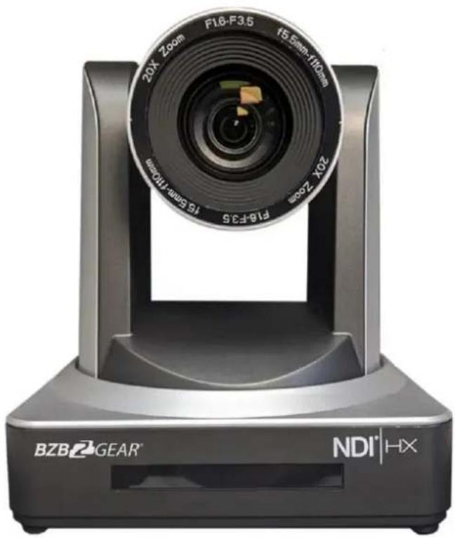
Electrical Safety
Installation and operation must conform with local electric safety standards.
Use care when moving
Avoid stress, vibration and moisture in transportation, storage and installation.
Polarity of power supply
The power supply of the product is ±12V, the max electrical current is 2A. Polarity of the power supply drawing.

Use Caution During Installation
Never move the camera by seizing the camera head. Never rotate the camera head by hand as mechanical damage may occur. Damage due to mishandling will void your warranty.
This unit must be installed on a smooth and level surface. Unit will not display level image if installed in a non-level position.
Ensure the base is solidly secured to the mounting surface.
Avoid using corrosive or abrasive materials to clean the camera as these may damage the finish.
Ensure that the camera is free of obstacles throughout its range of rotation.
Never power on before installation is completed.
Do not disassemble or open the housing. This will void your warranty!
To prevent the risk of electric shock, do not open the case. Installation and maintenance should only be carried out by qualified technicians. There are no serviceable parts inside the camera. BZB Gear is not responsible for any damage due to unauthorized disassembly.
Content
1. Quick Installation .... 4
1.1 Camera Overview 4
1.2 Power on initial configuration....0
1.3 Video Output....0
2. Product overview 2
2.1 Product Introduction ...... 2
2.1.1 Dimensions....3
2.1.2 Accessories .... 3
2.2 Main Features 4
2.2.1 Camera Performance .... 4
2.2.2 Network performance....4
2.3 Technical Specification....4
2.4 Connections Overview....5
2.4.1 External Connections 5
2.4.2 Bottom Dial Switch....6
2.4.3 RS-232 Interface....6
3. Operating Instructions....8
3.1 Video Output....8
3.1.1 Power-On Initial Configuration 8
3.1.2 Video Output 8
3.2 Remote Control 9
3.2.1 Key Description 9
3.2.2 Remote Control Operation 9
3.3 MENU SETTINGS....11
3.3.1 Main Menu....11
3.3.2 System Setting 12
3.3.3 Camera Setting 12
3.3.4 P/T/Z 15
3.3.5 Video Format 15
3.3.6 Version....16
3.3.7 Restore Defaults.... 16
- Network Connection .... 17
4.1 Connection Mode 17
4.2 Web Browser Login....18
4.2.1 Web client 18
2)Download/Install Plug in.... 18
4.2.2 Preview....19
4.2.4 Configuration....19
4.2.5 Audio Configuration....19
4.2.6 Video configuration.... 19
4.2.7 Network configuration 20
4.2.8 System configuration 21
4.2.9 Logout 22
4.2.10 Wireless network 22
- Serial Communication Control.... 22
5.1 VISCA protocol list 23
5.1.1 Camera return command 23
5.1.2 Camera control command 23
5.1.3, Inquiry command.... 26
5.2, Pelco-D protocol command list 27
5.3 Pelco-P protocol command list.... 28
- Camera Maintenance and Troubleshooting 28
6.1 Camera Maintenance 28
6.2 Troubleshooting 28
- Warranty....29
- Mission Statement 29
- Copyright Notice 30

NDI (Network Device Interface) technology provides the ability for multiple video systems to communicate via the Local Area Network by eliminating the requirement for Video cables like HDMI, DVI and SDI for streaming providing convenience and versatility. The technology was developed by NewTek to simplify remote connections and streaming, capture/playback, replay and production.
NDI cameras support bi-directional communication featuring ultra-low latency and ultra-high video streams on shared connections. Network requirements include 1GB Network using CAT5/6 cables for connectivity. Software programs offering NDI capturing will typically require NDI plugging be installed.
Note – NDI streaming uses more bandwidth than most streaming devices using standard video cables and capture devices. For this reason, it is recommended when using more than (2) NDI camera simultaneously it is a good idea to implement VLAN's. VLANS provide the ability to divide and segment Network bandwidth to optimize streaming without sacrificing quality of the stream or possible streaming interruptions from other devices connecting to the network. If you are having issues with streaming smoothly, this may be caused by Network traffic and a lack of bandwidth on the LAN.
EXAMPLES of standard NDI Versus NDI | HX Streaming Bandwidth Usage:
• 1920×1080@30 fps NDI stream requires minimum of 125 Mbps of dedicated bandwidth.
• 1920×1080@30 fps NDI|HX stream requires minimum of 8 to 20 Mbps of dedicated bandwidth.
Common Software Programs supporting NDI Plugins: (These plugins will need to be download for your program) vMix / OBS Studio's / VLC / Wirecast / Epiphan / ProPresenter
1. Quick Installation
1.1 Camera Overview
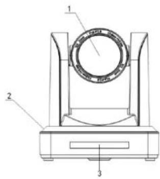

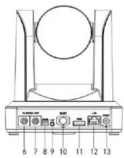
Figure 1.1 Interface
- Camera Lens
- Camera Base
- Remote Controller Receiver Light
- Bottom Dial Switch
- Tripod Screw Hole
- RS232 Control Interface (input)
- RS232 Control Interface (output)
- RS485 Input (left +, right-)
- Audio Input Interface
- 3G-SDI interface
- HDMI Interface
- 10/100M NDI/LAN Network Interface
- DC12V Input Power Supply Socket
1.2 Power on initial configuration
1) Power on: Connect DC12V power supply adapter with power supply socket.
2) Initial configuration: Power on with power indicator light on and remote control receiver light blinking, camera head moves from bottom left to the bottom, and then goes to the HOME position (intermediate position of both horizontal and vertical), while the camera module stretches. When remote control receiver light stops blinking, the self-checking is finished
Note: If you set preset 0, when Power on self-test is completed, the camera automatically moves to the preset 0 position.
1.3 Video Output
This model has video outputs from NDI-LAN, HDMI and 3G-SDI.
1) Video Output from NDI | HX LAN
a. Network Cable Connection Port: No.12 in Figure1.1
b. Webpage Login: Open your browser and enter 192.168.5.163 in the address bar (factory default); press Enter to reach the login page; click on "player is not installed, please download and install!" and follow the steps to install the plugin. When complete enter the username admin and password admin (factory default) and press Enter to reach the preview page. From here users can carry out PTZ control, system configuration and other operations.
2) HDMI Video Output
a. HDMI Video Cable Connection: refer to No.11 in Figure1.1.
b. Connect the camera and the monitor via HDMI video cable; video output is available after camera self-test.
3) 3G-SDI Video Output
a. 3G-SDI video cable connection: refer to No.10 in Figure1.1
b. Connect the camera and the monitor via 3G-SDI video cable; video output is available after camera self-test.
1.4 Bracket mount
Note: Bracket can be wall or ceiling mounted. Ensure bracket is securely fastened to a solid surface such as wood or concrete. Do not fasten to drywall or bracket may come loose and damage or destroy the camera.
1) Wall mount guide

M6 nut and shim
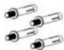
M6 swelling bolt

Wall mount bracket
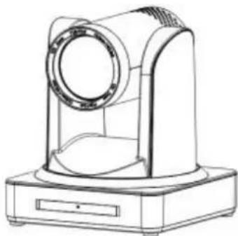
Camera

- Ceiling mount guide


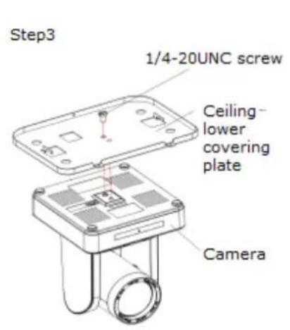

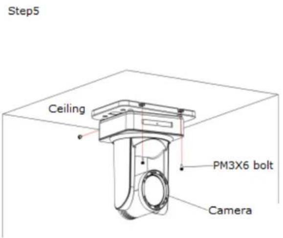
2. Product overview
2.1 Product Introduction
2.1.1 Dimensions
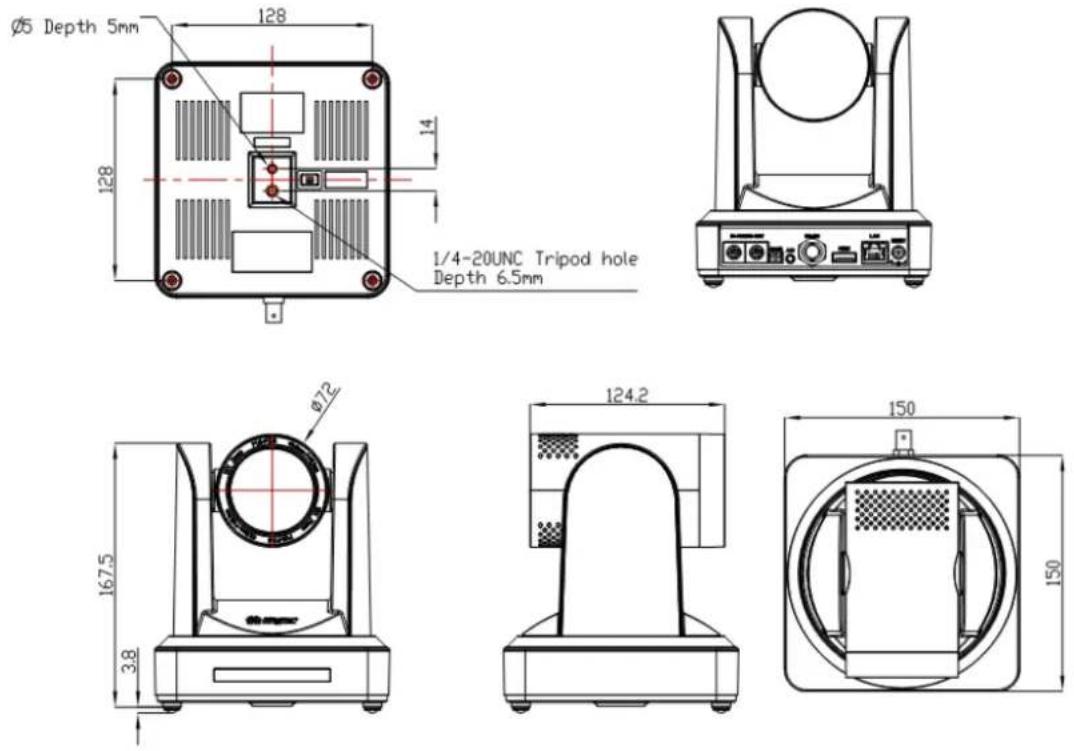
Figure 2.2 Camera Dimensions
2.1.2 Accessories
When you unpack, check that all the supplied accessories are included:
| Model NO. | Configuration | Accessories |
| BG-ND-20XHSRPBG-ND-30XHSRP | Standard | Power adapter 1 piece |
| RS232 cable 1 piece | ||
| User manual 1 | ||
| Double-side glue shim 4pcs | ||
| Warranty card 1 piece | ||
| Optional | IR Remote controller 1 piece | |
| Wireless controller 1 piece | ||
| Wall mounting bracket | ||
| Upside-down mounting bracket(optional) | ||
| Cascade cable |
USB2.0 Video cable: If need USB2.0 cable to provide power but not a power adapter, USB2.0 Video cable with two ports is needed, among which red port is for power supply and black port for transmitting USB video signals. If using a power adapter, the general USB2.0 video cable without power supply function is ok.
2.2 Main Features
2.2.1 Camera Performance
This camera offers superior performance and rich interfaces. Featuring NDI technology for Local Area Network broadcasting along with advanced ISP processing algorithms to provide vivid images with a strong sense of depth, high resolution and accurate color rendition. It supports H.265/H.264 encoding which makes motion video fluent and clear even with less than ideal bandwidth conditions.
- Superb High-definition Image: It employs a 1/2.8 inch high quality CMOS sensor. Resolution is up to 1920x1080 with frame rate up to 60 fps.
- Variable Optical Zoom Lens: It has 20X/30X optical zoom lens for options.
- Auto Focus Technology: Auto focus algorithm makes allows for fast, accurate, and stable auto-focusing.
- Low Noise and High SNR: Low Noise CMOS effectively ensures high SNR of camera video.
Advanced 2D/3D noise reduction technology is also used to further reduce the noise, while ensuring image sharpness. - Quiet PTZ: By adopting a high accuracy step driving motor mechanism, it works extremely quietly while moving smoothly and quickly to the designated position.
6.Multi-Format Video Outputs: Supports HDMI, 3G-SDI, wired NDI | HX LAN, and wireless LAN interfaces. 3G-SDI provides a 1080p60 signal up to 100m. - Multiple Remote Controls: Included IR and optional 2.4G wireless remote controls. The 2.4G wireless remote controller will not be affected by angle, distance or IR interference. Supports transparent transmission function.
- Low-power Sleep Function: Supports low-power sleep/wake up, consumption is lower than 500mW under sleep mode
- Support Multiple Control Protocol: Supports VISCA, PELCO-D, and PELCO-P protocols which can be automatically recognized. Supports VISCA control protocol through IP port.
10.RS-232 Cascade Function: supports RS-232 cascade function which is convenient for installing.
11.255 Presets Positions: Up to 255 presets (10 presets by remoter).
2.2.2 Network performance
- Audio Input Interface: Supports 16000, 32000, 44100, 48000 sampling frequency and AAC, MP3, PCM audio coding.
- Multiple Audio/Video Compression: Support H.264/H.265 video compression; AAC, MP3 and PCM audio compression; Support compression of resolution up to 1920x1080 with frame rates up to 60 fps and 2 channel 1920x1080p with 30 fps compression.
- Multiple network protocol: Supports ONVIF, RTSP, and RTMP protocols as well as RTMP push mode making it easy to link streaming media servers. (Wowza, FMS)
- 5G WIFI function: If the product contains the 5G module, you can connect and transmit via WiFi.
2.3 Technical Specification
| Model | 20X | 30X |
| Camera Parameter | ||
| Sensor | 1/2.8 inch high quality HD CMOS sensor | |
| Effective Pixels | 16: 9 2.07 megapixel | |
| Video Format | HDMI/SDI/NDI video format1080P60/50/30/25/59.94/29.97;1080I60/50/59.94;720P60/50/30/25/59.94/29.97 | |
| Optical Zoom | 20Xf=5.5~110mm | 30Xf=4.3~129mm |
| View Angle | 3.3° (tele)54.7° (wide) | 2.34° (tele)65.1° (wide) |
| AV | F1.6 – F3.5 | F1.6– F4.7 |
| Digital Zoom | 20X/30X | |
| Minimum Illumination | 0.5Lux (F1.8, AGC ON) | |
| DNR | 2D & 3D DNR | |
| White Balance | Auto / Manual/ One Push/ 3000K/ 4000K/5000K/6500K | |
| Focus | Auto/Manual | |
| Aperture | Auto/Manual | |
| Electronic Shutter | Auto/Manual | |
| BLC | ON/OFF | |
| WDR | OFF/ Dynamic level adjustment | |
| Video adjustment | Brightness, Color, Saturation, Contrast, Sharpness, B/W mode, Gamma curve | |
| SNR | >55dB | |
| Input/Output Interface | |
| Video Interfaces | BG-ND-20XHSRP / BG-ND-30XHSRP: HDMI, 3G-SDI, NDI-LAN. |
| Image code stream | Double streams outputs simultaneously |
| Video Compression format | H.264, H.265 |
| Control Signal Interface | RS-232 Ring through RS232 output, RS-485 |
| Control Protocol | VISCA/Pelco-D/Pelco-P; Baud Rate: 115200/9600/4800/2400bps |
| Audio input Interface | Double track 3.5mm linear input; |
| Audio Compression Format | AAC/MP3/PMC Audio compression |
| HD IP Interface | 100M IP port(100BASE-TX); 5G WiFi (optional), support NDI & IP Visca control protocol |
| Network Protocol | NDI, RTSP/RTMP, ONVIF |
| Power Interface | HEC3800 outlet (DC12V) |
| PTZ Parameter | |
| Pan Rotation | ±170° |
| Tilt Rotation | -30°~+90° |
| Pan Control Speed | 0.1 -180°/sec |
| Tilt Control Speed | 0.1-80°/sec |
| Preset Speed | Pan: 60°/sec, Tilt: 30°/sec |
| Preset Number | 255 presets (10 presets by remote controller) |
| Other Parameters | |
| Supply Adapter | AC110V-AC220V to DC12V/2A |
| Input Voltage | DC12V±10% |
| Input Current | 1A(Max) |
| Consumption | 12W (Max) |
| Store Temperature | -10°C to +60°C |
| Store Humidity | 20% - 95% |
| Working Temperature | -10°C to +50°C |
| Working Humidity | 20%--80% |
| Dimension | 150mmX150mmX167.5mm |
| Weight | 1.4KG |
| Working Environment | Indoor |
| Remote Operation (IP) | Remote Upgrade, Reboot and Reset |
| Accessory | Power Supply, RS232 Control Cable, Remoter, Manual, Warranty card |
| Optional Accessory | Bracket |
2.4 Connections Overview
2.4.1 External Connections
1) External interface: RS232 Input /Output, RS485 Input, Audio Input, 3G-SDI Output, HDMI Output, NDI|HX LAN, DC12V Power Interface.
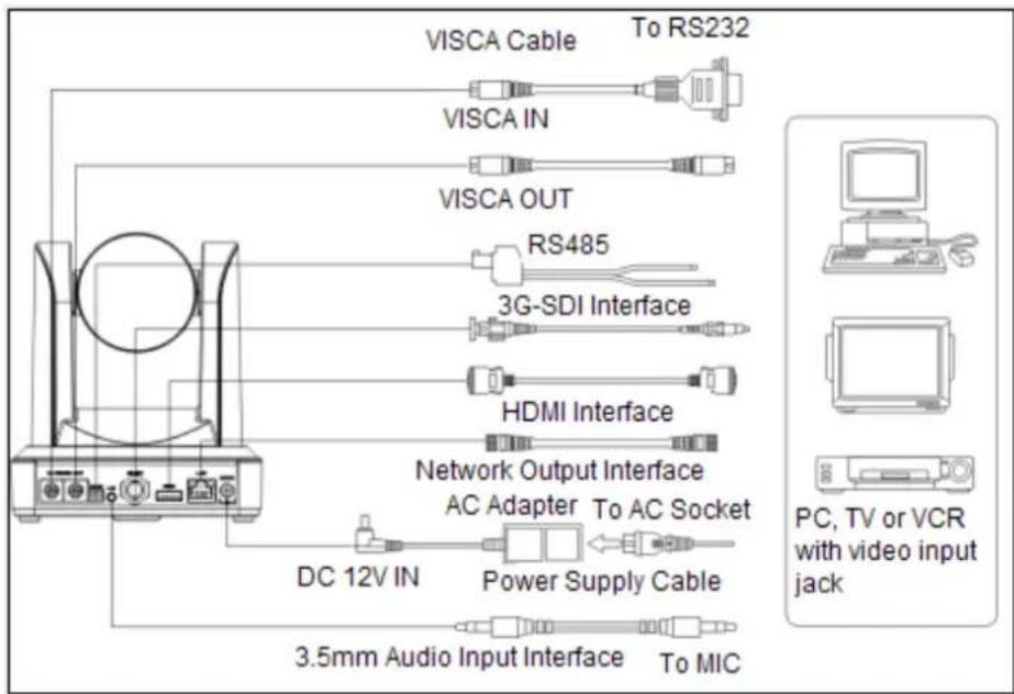
Figure 2.3 external interface diagram
2.4.2 Bottom Dial Switch
Bottom Dial Switch diagram shown in Figure 2.6 and 2.7:

Figure 2.6 Bottom Dial Switch Diagram
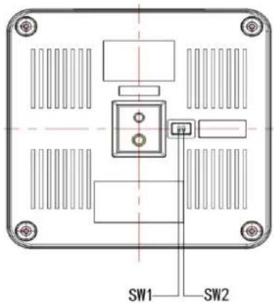
Figure 2.7 Bottom Dial Switch diagram
Two DIP switches are set to ON or OFF to select different modes of operation as shown in Table 2.2
Table 2.2 Dial Switch setting
| No. | SW1 | SW2 | Explanation |
| 1 | OFF | ON | Working mode |
| 2 | ON | OFF | Updating mode |
2.4.3 RS-232 Interface
1) RS-232C interface specification as shown below
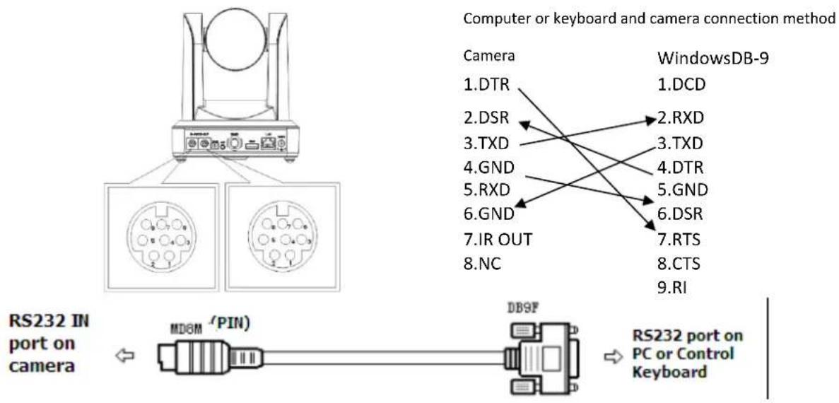
2) RS-232 Mini-DIN 8-pin Port Definition
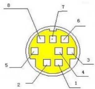
| NO. | Port | Definition |
| 1 | DTR | Data Terminal Ready |
| 2 | DSR | Data Set Ready |
| 3 | TXD | Transmit Data |
| 4 | GND | System Ground |
| 5 | RXD | Receive Data |
| 6 | GND | System Ground |
| 7 | IR OUT | IR Commander Signal |
| 8 | NC | No Connection |
3) RS232 (DB9) Port Definition
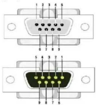
| NO. | Port | Definition |
| 1 | DCD | Data Carrier Detect |
| 2 | RXD | Receive Data |
| 3 | TXD | Transmit Data |
| 4 | DTR | Data Terminal Ready |
| 5 | GND | System Ground |
| 6 | DSR | Data Set Ready |
| 7 | RTS | Request to Send |
| 8 | CTS | Clear to Send |
| 9 | RI | Ring Indicator |
2) VISCA networking as shown below:
![graph TD A["VISCA Controller"] --> B["VISCA Equipment"] B --> C["IN OUT"] B --> D["IN OUT"] B --> E["IN OUT"] C --> F["Output"] D --> G["Output"] E --> H["Output"]](/content/2026/05/1009238/images/9622fa983f245d61882cad45237880716a3df088324db12386a27ba9d61c2569.jpg)
Camera cascade connection method
![graph TD A["1.DTR"] --> B["2.DSR"] B --> C["3.TXD"] C --> D["4.GND"] D --> E["5.RXD"] E --> F["6.GND"] F --> G["7.IR OUT"] G --> H["8.NC"] I["1.DTR"] --> J["2.DSR"] J --> K["3.TXD"] K --> L["4.GND"] L --> M["5.RXD"] M --> N["6.GND"] N --> O["7.OPEN"] O --> P["8.OPEN"]](/content/2026/05/1009238/images/5f18ef5671dd599d9584847cc786658412605ebb9f481228c4d561508575a6c3.jpg)
Note: Has RS232 input and output interface allowing for cascading inputs.
3. Operating Instructions
3.1 Video Output
3.1.1 Power-On Initial Configuration
After connecting the power, the camera will initiate self-test mode. The IR indicator light will start flashing. When the camera returns to the HOME position (middle position for P/T) and lens finishes zoom in/out, the self-testing is finished. The IR led will stop flashing. If the preset 0 is set, the camera will rotate to the (0) preset position after initial configuration.
3.1.2 Video Output
Connect the video output cable; this may vary based on camera model and application.
Figure 1.4.1 is for your reference (output interface introduction for each product)
1) NDI Network Output: Connect this product and your computer via network cable. Open the browser and enter the camera IP address (factory default 192.168.5.163) in the address bar. On the login page enter username and password - factory default is "admin" for both. Once logged in you will be prompted to download and/or enable manage the plugin, click allow and video will be displayed.
(Note: If you forget your username, password, IP address, you can manually restore the default by the remote controller key combination * #)
2) 3G-SDI output or DVI (HDMI) output: Connect the monitor with the corresponding video output interface and the image will be displayed after initial power-on.
3.2 Remote Control

3.2.1 Key Description
1. Power/Standby Key
Press and hold for 3 seconds to place the camera into standby mode. Press and hold for 3 seconds a second time and the camera will self-test again and return to the HOME position. Note: Camera will default to preset 0 if no command is sent within 12 seconds of power on.
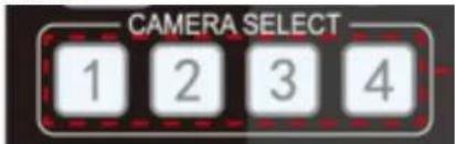
2. Camera Select
Select the ID of the camera you wish to control.
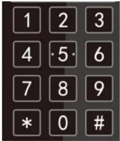
3. Number Key
Set or run preset 0-9.
4.* # Key
Used for command modifiers – See tables in sections 11 and 12 below.
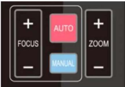
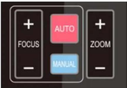
5. Focus Control Key
Auto: Activate auto focus mode.
Manual: Activate manual focus mode.
+/-: Adjust focus in manual focus mode.
6. Zoom Control Key
Zoom+: Zoom In
Zoom—: Zoom Out
7. Set or Clear Preset key:
Set Preset: Press and hold while selecting desired number key to record a preset.
Clear Preset key: Press and hold while selecting desired number key to clear a preset.
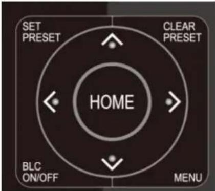
8. Pan/Tilt Control Key
▲ Tilt camera up
▼ Tilt camera down
Pan camera left
Pan camera right
HOME: Return to the middle position/ confirm on-screen menu selection.
9. BLC ON/OFF
Turn on or off remote control button backlighting.
10. MENU
Enter or exit on-screen menu/previous menu.
11. Camera IR Remote Control Address Setting
【*】+【#】+【F1】:Camera Address No.1
【*】+【#】+【F2】:Camera Address No. 2
【*】+【#】+【F3】:Camera Address No. 3
3.2.2 Remote Control Operation
Following initialization, the camera can receive and execute the IR commands. The indicator will flash when the camera receives a command. Users can control the pan/tilt/zoom, settings, and run preset positions via the IR remote controller.
Key Instruction:
- In this instruction, "press the key" means a click rather than a long-press, and a special note will be given if a long-press for more
than one second is required.
- When a key-combination is required, do it in sequence. For example, “【*】+【#】+【F1】” means press “【*】” first, then press “【#】” and last press “【F1】”.
1) Camera Selection
2) Pan/Tilt Control
3) Zoom Control
4) Focus Control
5) BLC Setting

6) Presets - Setting, Running, Clearing
Select the camera address to control.
Up: press ▶ Down: press ▶ Left: press ▼ Right: press ▶ Back to middle position: press "【HOME】"
Press and hold the up/down/left/right key, the pan/tilt will keep running, from slow to fast, until it runs to the endpoint; the pan/tilt running stops as soon as the key is released.
ZOOM IN: press "ZOOM" key
ZOOM OUT: press "ZOOM key
Press and hold the key, the camera will keep zooming in or zooming out and stop as soon as the key is released.
Focus (near): Press “【focus+】” key (Valid only in manual focus mode)
Focus (far): Press "【focus-】"key (Valid only in manual focus mode)
Auto Focus: Support
Manual Focus: Support
Press and hold the key, the action of focus will keep continue and stops as soon as the key is released.
BLC ON / OFF: support

7) Camera Remote Controller Address Setting

- Preset setting: to set a preset position, the users should press the "【SET PRESET】" key first and then press the number key 0-9 to record a preset.
Note: 10 preset positions in total are available by remote controller.
-
Preset Running: Press a number key 0-9 to run a preset.
-
Preset Clearing: To clear a preset position, the user can press the "【CLEAR PRESET】" key first and then press the number key 0-9 to clear the preset.
Note: press the “【#】” key three times to erase all presets.
【*】+【#】+【F1】:Camera Address No.1
【*】+【#】+【F2】:Camera Address No. 2
【*】+【#】+【F3】:Camera Address No. 3
In normal working mode, press 【MENU】key to display the menu and use the arrow keys to navigate the options.
![MENU ==================== Language English (Setup) (Camera) (P/T/Z) (Video Format) (Version) (Restore Default) [↑↓]Select [←→]Change Value [Menu]Back |Home|OK](/content/2026/05/1009238/images/c7b78a74b9dc906a4bf00571b8ef1a400e691c3a5c1e58d4b45b3fd25237559f.jpg)
LANGUAGE: Language setting, Chinese / English
SETUP: System setting
CAMERA OPTION: Camera setting
PTZ OPTION: Pan tilt setting
VERSON: camera version setting
Restore Default: Reset setting
[↑↓] Select: for selecting menu
[←→] Change Value: for modify parameters
[MENU] Back: Press [MENU] to return
[Home] OK: Press [Home] to confirm
3.3.2 System Setting
Move the pointer to the (Setup) in the Main Menu, click the 【HOME】 key and enter the (System Setting) as shown below.

PROTOCOL: VISCA/Pelco-P/Pelco-D/Auto
Visca ADDR: VISCA=1\~7 Pelco-P=1\~255 Pelco-D = 1\~255
Baud rate: 2400/4800/9600/115200
Visca Address Fix: On/Off
3.3.3 Camera Setting
Highlight (CAMERA) in the Main Menu, click the 【HOME】 key to enter camera settings.
![CAMERA ------------------------ (Exposure) (Color) (Image) (Focus) (Noise Reduction) [↑↓]Select [←→]Change Value](/content/2026/05/1009238/images/77aed982e09f7fdd5e93d352473663c9da5c3c639b6db6cdf0cec978f172470e.jpg)
EXPOSURE: Enter Exposure setting
COLOR: Enter color setting
Image: Enter into image setting
Focus: Enter into focus setting
Noise Reduction: Enter noise reduction
1) EXPOSURE SETTING
Highlight (EXPOSURE) in the Main Menu, click the 【HOME】 key to enter exposure settings.
![EXPOSURE Mode Auto EV OFF BLC OFF Anti-Flicker 50Hz Gain Limit 3 WDR 5 [↑↓]Select [←→]Change Value](/content/2026/05/1009238/images/fdc3beee67dd83e2c9f33f2fa2516008e1665844154f498680e1960c54d25984.jpg)
Mode: Auto, Manual, Shutter priority, Iris priority and Brightness priority.
EV: On/Off (only available in auto mode)
Compensation Level: -7\~7 (only available in auto mode when EV is ON)
BLC: ON/OFF for options (only available in auto mode)
Anti-Flicker: OFF/50Hz/60Hz for options (only available in Auto/Iris priority/Brightness priority modes)
Gain Limit: 0\~15 (only available in Auto/ Iris priority /Brightness priority mode)
WDR: Off,1\~8
Shutter Priority: 1/25,1/30,1/50,1/60,1/90,1/100,1/120,1/180,1/250,1/350,1/500,1/1000,1/2000,1/3000,1/4000,1/6000,1/10000
(only available in Manual and Shutter priority mode)
IRIS Priority: OFF,F11.0,F9.6,F8.0,F6.8,F5.6,F4.8,F4.0,F3.4,F2.8,F2.4,F2.0,F1.8 (only available in Manual and Iris priority mode)
Brightness: 0\~23 (only available in Brightness priority mode)
2) COLOR SETTING
Highlight (COLOR) in the Main Menu and click the 【HOME】 key to enter Color Settings.

WB Mode: Auto, Manual, One Push
Red Gain: 0\~255(only available in Manual mode)
Blue Gain: 0\~255(only available in Manual mode)
Saturation: 60%, 70%, 80%, 90%, 100%, 110%, 120%, 130%
Hue: 0\~14
AWB Sensitivity: high/middle/low
Color Style: Default, style1\~4.
Color Temp: high/middle/low
3) IMAGE
Highlight (IMAGE) in the Menu and click the 【HOME】 key to enter Image Settings.
| IMAGE | |
| Brightness | 6 |
| Contrast | 8 |
| Sharpness | 7 |
| Flip-H | OFF |
| Flip-V | OFF |
| B&W-Mode | |
| Color | |
| Gamma | |
| Default | |
| DZoom | |
| OFF | |
| DCI | Close |
Brightness: 0\~14
Contrast: 0\~14
Sharpness: 0\~15
Flip-H: On/Off
Flip-V: On/Off
B&W Mode: color, black/white
Gamma: default, 0.47, 0.50, 0.52, 0.55
DZoom: digital zoom options: On/Off
DCI: Dynamic Contrast: Off,1\~8
4) FOCUS
Highlight (FOCUS) in the Menu and click the 【HOME】 key to enter Focus Settings.
| FOCUS |
| ---- |
| Focus Mode |
| Auto |
| AF-Zone |
| Center |
| AF-Sensitivity Low |
Focus Mode: Auto, manual
AF-Zone: Up, middle, down
AF-Sensitivity: High, middle, low
5) NOISE REDUCTION
Highlight (NOISE REDUCTION) in the Menu and click the 【HOME】 key to enter Noise Reduction Settings.

2D Noise Reduction: Auto, close, 1\~7
3D Noise Reduction: Close, 1\~8
Dynamic Hot Pixel: Close, 1\~5
3.3.4 P/T/Z
Highlight (P/T/Z) in the Main Menu and click the 【HOME】 key to enter P/T/Z Settings.
![P/T/Z --------= Depth of field ON Zoom speed 8 Image Freezing OFF Acc Curve Slow [↑↓]Select [←→]Change](/content/2026/05/1009238/images/f79073769401fed1b5b5b2a00801da46a8bccc843dc5b98043cb9a235f1ba858.jpg)
Depth of Field: Only effective for remote controller, On/ Off
*When zoomed in the PT control speed by remote will slow down.
Zoom Speed: Set the zoom speed for remote controller,1\~8
Image Freezing: On/Off
Accelerating Curve: Fast/slow
3.3.5 Video Format
Highlight (Video Format) in the Menu and click the 【HOME】 key to enter Video Format Settings

Note: 1. S: 1080P60 Downward Compatibility; M: 1080P30 Downward Compatibility
2. Exit menu after modifying parameter to save it after powered off
3.3.6 Version
Highlight (VERSION) in the Main Menu and click the 【HOME】 key to enter Version Information.
![VERSION MCU Version 2.0.0.15 2015-12-18 Camera Version 2.0.0.13 2015-12-18 AF Version 2.0.0.6 2015-12-11 Lens 12X(20X) [Menu]Back](/content/2026/05/1009238/images/6811b1192b3ffa5dfe64e29021cafe82439e81f0f13d6b2b3add8b347d74b1cd.jpg)
MCU Version: Display MCU version information
Camera Version: Display camera version information
AF Version: Display the focus version information
Lens: Display the lens zoom
Highlight (RESTORE DEFAULT) in the Main Menu and click the 【HOME】 key to enter Restore Default Settings.
![graph TD A["RESTORE DEFAULT"] --> B["Restore Default?"] B --> C["NO"] C --> D["[↑↓"]Select] C --> E["[←→"]Change] D --> F["Value"]](/content/2026/05/1009238/images/9d9a3c3449544fd8a93e80455845e4b2603773c41217b7a9e5079fc07d2d02fa.jpg)
Restore default: options: yes/no; after restoring default, the video format will not be restored.
4. Network Connection
4.1 Connection Mode
Direct connection: Connect the camera directly to the computer by using an ethernet cable.
Internet connection mode: Connect the camera and computer to a router or switch and access via the local area network (LAN).
Note: Ensure power and network connections are secured to prevent video issues caused by poor connection quality.
The computer must be on the same subnet as the camera to connect successfully. The device will not be accessible otherwise. The camera default IP address is 192.168.5.163, therefore the computer must be connected to the 192.168.5.x subnet.
To connect to the camera, open the Local Area Connection Properties on the computer.
For Windows users right-click on the internet connection in the lower right corner of the desktop.
Select "Open Network & Internet Settings".
Select "Change Adapter Options".
Right-click on your connection (Wi-Fi or Ethernet) and select "Properties".
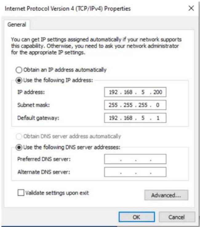
Select "Internet protocol version 4 (TCP/IPv4)" as shown below and click "Properties".

For the following steps refer to the diagram below.
Click on the bubble for "Use the following IP address"
In the IP address field enter a non-conflicting IP address on the same subnet as the camera. If there is another device with the same IP address you will not be able to connect. In the example below we are using 192.168.5.200
In the Subnet mask field enter 255.255.255.0
In the Default gateway field type 192.168.5.1
You can leave the DNS fields blank.
Click OK to apply your settings.
NOTE: When you are finished configuring the camera you will need to return to this screen and click the bubbles for "Obtain an IP address automatically" and "Obtain DNS server automatically" to restore internet connectivity to your computer. Also make sure to reconnect any ethernet cables you may have unplugged.
4.2 Web Browser Login
4.2.1 Web client
1) Web client Log In
Enter 192.168.5.163 in the address bar of your internet browser and click Enter. If logged in as administrator (Default Username/Password: admin), users can preview and configure in the Web Client. If logged in as a normal user (Default Username/Password:user1 or user2), users can only preview with no options for configuration.
2) Download/Install Plug in
The first time you connect to the camera you will receive a prompt to allow the Flash player to run. This is required to display the image in your web browser.
4.2.2 Preview
After successful login into the web UI you will see the video preview interface. From the preview screen users can control PTZ, zoom, focus, sound and screen size. Additionally, run and delete preset positions and perform other operations.
4.2.4 Configuration
Click Configuration access the following settings.
| Menu | Explanation |
| Audio configure | Including audio compressing format,sampling frequency,sampling precision,compressing code rate settings etc. |
| Video configure | Including video encoding,video parameters,character-overlapping,character size,video output setting etc. |
| Network configure | Including basic parameters,Ethernet,DNS,wireless network setting, GB28181 etc. |
| System configure | Including equipment property,system time,user management,version update,Reset,Reboot device settings etc. |
4.2.5 Audio Configuration
Checkbox: Select to enable audio.
Encode Type: Set audio compression format
Sample Rate: Set sampling rate
Sample Bits: Set sampling precision
Bit rate: Set audio compression bit rate
Note: After clicking "SAVE" you will be prompted to reboot the camera. This is required to apply changes.
4.2.6 Video configuration
1) Video encoding
Stream: Designates which stream the settings apply to.
Compression Format: Set the video compression format; reboot required to apply changes.
Profile: Profile Mode Setting
Image Size: Set video image resolution; reboot required to apply changes.
Stream Rate control: Set rate control mode; reboot required to apply changes.
Image Quality: Set image quality - Can be changed only when rate control is set to variable bit rate (VBR)
Bit Rate (Kb / s): Set the video bit rate
Frame rate (F / S): Set the video frame rate
I frame interval: Set the key frame interval
Stream Name: When streaming via RTSP or RTMP, user can modify stream name.
Click SAVE to apply changes.
2) Stream Publish
Checkbox: To turn enable/disable main or secondary stream.
Protocol Type: Primary and secondary streams use RTMP protocol.
Host Port : Server port number.
Host Address: Server IP addresses
Stream Key: Copy Paste a Stream Key
Username: Set the username
Password: Set the password
Click SAVE to apply changes.
*To use RTSP use the following string in "Stream Name": rtsp: // device IP address: 554 / live / av0 (av0 main stream; av1 secondary stream)
3) RTP Multicast
Checkbox: Click to enable/disable main or secondary stream.
Protocol Type: Select protocol type
Multicast Address: Server IP address
Multicast Port: Server port number
4) Video Parameters
Focus: Focus mode, focus range, focus sensitivity can be set.
Focus Mode: set the focus mode
Focus Range: set the focus range
Focus Sensitivity: Set the focus sensitivity
Exposure: Mode, compensation, back light compensation, anti-flicker, gain limit, and dynamic range compression can be set.
Exposure Mode: Set the exposure mode
Exposure compensation: Enable exposure compensation
BLC: Enable back light compensation
Anti-flicker: Set anti-flicker mode
Gain limit: Set the gain
DRC: Set the dynamic range compression
Color: White balance, saturation, color, sensitivity, color temperature, red and blue gain can be set.
White balance mode: Set the white balance
Red Gain: Set the red gain
Blue Gain: Set the blue gain
Saturation: Set the saturation
Auto white balance sensitivity: Auto white balance settings
Image: Brightness, contrast, sharpness, gamma curve, black and white mode, horizontal/vertical flip can be set.
Brightness: Set the brightness
Contrast: Set the contrast
Sharpness: Set the sharpness
Gamma: Gamma value setting
DCI: Set the DCI level
Black and white mode: Set black and white mode
Flip Horizontal: Set Flip Horizontal
Flip Vertical: Set vertical flip
Noise Reduction: 2D noise reduction, 3D noise reduction and dynamic dead pixel correction available.
2D Noise Reduction: Set 2D noise reduction level
3D Noise Reduction: Set 3D noise reduction level
Dynamic hot pixel correction: Set Dynamic hot pixel correction
Style: Image style preset can be selected
Video OSD: Video overlay information can be set
Display date and time: Set whether to display the time and date
Display Title: Set whether to display the title
Time Font Color: Set font color of time and date
Title Font Color: Set font color of
Moving characters: Set the display position of date, time, and title
Title Content: Set title content
Time Content: Set time content
OSD Font Size
Main stream OSD font size: Set the character size of the display
Secondary stream character size: Set the character size of the display
Click "Save" to apply changes.
Video output
Video Out Format: Set the video output
Click "Save" to apply changes.
4.2.7 Network configuration
1) Network port
Port Data: Set the data port
Port Web: Set the web port
Port Onvif: Set Onvif port
Port Soap: Set Soap port
Port RTMP: Set RTMP port
Port Rtsp: Set RTSP port
Port Visca: Set Visca
Click "Save" to apply changes.
RTMP access: RTMP: // equipment IP address: 1935 / live/av0 (av0 main stream; av1 second stream)
2) Ethernet
DHCP: Enable or disable obtain IP automatically
IP Address: Set the camera IP address
Subnet Mask: Set the subnet mask
Default Gateway: Set the default gateway
MAC Address: Displays the camera's MAC address.
Click "Save" to apply changes.
3) DNS parameters
Preferred DNS server: set the preferred DNS server
Alternate DNS server: Alternate DNS server settings
Click "Save" to apply changes.
4) GB28181
Checkbox: Enable/Disable GB28181
Clock Sync: Enable/Disable clock synchronization
Video Type: Stream type setting
Registration Valid Time (seconds): 3600 Range 5-65535
Heartbeat time (seconds): 60 Range 1-65535
Register ID: 34020000001320000001
Register Name: IPC
Register Password: 12345678
Equipment ownership: Users can add their own
Administrative regions: Users can add their own
Alarm Areas: Users can add their own
Device Address: Users can add their own
Local SIP Port: 5060 Range 0-65535
GB28181 Server Address: IP address of the computer
Server SIP Port: 5060 Range 0-65535
Server ID: 34020000002000000001
Click "Save" to apply changes.
4.2.8 System configuration
1) System Attributes
Device Name: Set the device name
Device ID: Shows the device ID
System Language: Set the system language
Click "Save" to apply changes.
2) System Time
Date Format: Set the date format
Date separator: Set the date separator
Time Zone: Set the time zone
Hour Type: Set the clock type
NTP Enable: Enable automatic time sync
Update interval: Set the NTP server automatic time update interval
Host URL: Set NTP server address or domain name
Host Port: Sets the NTP server
Click "Save" to apply changes.
3) User Management
Authority: Set the user type (Administrator, Common User 1, Common User 2)
Username: Set the username
Password: Set a password
Password confirmation: Confirm the password
Click "Save" to apply changes.
4) Update
MCU version: Displays current firmware version
Camera version: Displays current firmware version
Focus version: Displays current firmware
Update file: Click choose file to browse for firmware update file. Click Upgrade when file is selected.
* Make sure power and network remain connected during process or the upgrade will fail!
5) Default
Click on "Restore Factory Defaults" button and choose "yes" or "no"
6) Reboot
Click on the pop-up "Reboot" button and choose "yes" or "no"
4.2.9 Logout
Click "Logout" button; select "Yes" or "No"
4.2.10 Wireless network
If the user's equipment has a wireless network module, the specific configuration is as follows:
1) Network settings
Wireless network configuration:
Network interface enable: Select to enable wireless interface
DHCP: Select to enable DHCP (default is disabled with a static address of 192.168.1.250)
*Note: Wireless IP address cannot be in the same subnet as wired IP address!
Subnet Mask: Set the wireless IP subnet mask (default255.255.255.0)
Default Gateway: Set the wireless IP default gateway (default 192.168.1.1)
SSID: The user can modify their own (the default test)
Encryption: Select to enable password entry
Password: Enter Wifi password
Click "Save" to apply changes.
2) WiFi hot link
Click on the "search" button to scan for WIFI hotspots.
Double-click the dialog box after selecting Wifi hotspot, then input password to connect to Wifi.
3) Wireless WiFi login page
Enter IP address of camera to login via browser. Default is 192.168.1.250. Use a network scanning tool to locate your IP address if DHCP was enabled in setup.
5. Serial Communication Control
Under common working conditions the camera can be controlled through RS232/RS485 interface (VISCA), RS232C serial parameter are as follows:
Baud rate: 2400/4800/9600/115200 bits / sec; Start bit: 1; data bits: 8; Stop bit: 1; Parity: None.
After powering on, the camera will perform a self-test. Self-test is finished after the zoom moves to the farthest and then back to the nearest position. If the camera has a "0" preset stored it will return to that position after initialization. At this point, the user can control the camera by the serial commands.
5.1 VISCA protocol list
5.1.1 Camera return command
| Ack/Completion Message | ||
| Command packet | Note | |
| ACK | z0 41 FF | Returned when the command is accepted. |
| Completion | z0 51 FF | Returned when the command has been executed. |
z = camera address + 8
| Error Messages | ||
| Command packet | Note | |
| Syntax Error | z0 60 02 FF | Returned when the command format is different or when a command with illegal command parameters is accepted |
| Command Not Executable | z0 61 41 FF | Returned when a command cannot be executed due to current conditions. For example, when commands controlling the focus manually are received during auto focus. |
5.1.2 Camera control command
| Command | Function | Command packet | Note |
| AddressSet | Broadcast | 88 30 0p FF | p: Address setting |
| IF_Clear | Broadcast | 88 01 00 01 FF | I/F Clear |
| CommandCancel | 8x 21 FF | ||
| CAM_Power | On | 8x 01 04 00 02 FF | Power ON/OFF |
| Off | 8x 01 04 00 03 FF | ||
| CAM_Zoom | Stop | 8x 01 04 07 00 FF | |
| Tele(Standard) | 8x 01 04 07 02 FF | ||
| Wide(Standard) | 8x 01 04 07 03 FF | ||
| Tele(Variable) | 8x 01 04 07 2p FF | p = 0(low) - F(high) | |
| Wide(Variable) | 8x 01 04 07 3p FF | ||
| Direct | 8x 01 04 47 0p 0q 0r 0s FF | pqrs: Zoom Position | |
| CAM_Focus | Stop | 8x 01 04 08 00 FF | |
| Far(Standard) | 8x 01 04 08 02 FF | ||
| Near(Standard) | 8x 01 04 08 03 FF | ||
| Far(Variable) | 8x 01 04 08 2p FF | p = 0(low) - F(high) | |
| Near (Variable) | 8x 01 04 08 3p FF | ||
| Direct | 8x 01 04 48 0p 0q 0r 0s FF | pqrs: Focus Position | |
| Auto Focus | 8x 01 04 38 02 FF | ||
| Manual Focus | 8x 01 04 38 03 FF | ||
| CAM_Zoom Focus | Direct | 8x 01 04 47 0p 0q 0r 0s 0t 0u 0v 0w FF | pqrs: Zoom Position tuvw: Focus Position |
| CAM_WB | Auto | 8x 01 04 35 00 FF | |
| 3000K | 8x 01 04 35 01 FF | ||
| 4000k | 8x 01 04 35 02 FF | ||
| One Push mode | 8x 01 04 35 03 FF | ||
| 5000k | 8x 01 04 35 04 FF | ||
| Manual | 8x 01 04 35 05 FF | ||
| 6500k | 8x 01 04 35 06 FF | ||
| CAM_RGain | Reset | 8x 01 04 03 00 FF | Manual Control of R Gain |
| Up | 8x 01 04 03 02 FF | ||
| Down | 8x 01 04 03 03 FF | ||
| Direct | 8x 01 04 43 00 00 0p 0q FF | pq: R Gain | |
| CAM_Bgain | Reset | 8x 01 04 04 00 FF | Manual Control of B Gain |
| Up | 8x 01 04 04 02 FF | ||
| Down | 8x 01 04 04 03 FF | ||
| Direct | 8x 01 04 44 00 00 0p 0q FF | pq: B Gain | |
| CAM_AE | Full Auto | 8x 01 04 39 00 FF | Automatic Exposure mode |
| Manual | 8x 01 04 39 03 FF | Manual Control mode | |
| Shutter priority | 8x 01 04 39 0A FF | Shutter Priority Automatic Exposure mode | |
| Iris priority | 8x 01 04 39 0B FF | Iris Priority Automatic Exposure mode | |
| Bright | 8x 01 04 39 0D FF | Bright mode | |
| CAM_Shutter | Reset | 8x 01 04 0A 00 FF | Shutter Setting |
| Up | 8x 01 04 0A 02 FF | ||
| Down | 8x 01 04 0A 03 FF | ||
| Direct | 8x 01 04 4A 00 00 0p 0q FF | pq: Shutter Position | |
| CAM_Iris | Reset | 8x 01 04 0B 00 FF | Iris Setting |
| Up | 8x 01 04 0B 02 FF | ||
| Down | 8x 01 04 0B 03 FF | ||
| Direct | 8x 01 04 4B 00 00 0p 0q FF | pq: Iris Position | |
| CAM_Gain Limit | Gain Limit | 8x 01 04 2C 0p FF | p: Gain Position |
| CAM_Bright | Reset | 8x 01 04 0D 00 FF | Bright Setting |
| Up | 8x 01 04 0D 02 FF | ||
| Down | 8x 01 04 0D 03 FF | ||
| Direct | 8x 01 04 4D 00 00 0p 0q FF | pq: Bright Position | |
| CAM_ExpComp | On | 8x 01 04 3E 02 FF | Exposure Compensation ON/OFF |
| Off | 8x 01 04 3E 03 FF | ||
| Reset | 8x 01 04 0E 00 FF | Exposure Compensation Amount Setting | |
| Up | 8x 01 04 0E 02 FF | ||
| Down | 8x 01 04 0E 03 FF | ||
| Direct | 8x 01 04 4E 00 00 0p 0q FF | pq: ExpComp Position | |
| CAM_Back Light | On | 8x 01 04 33 02 FF | Back Light Compensation |
| Off | 8x 01 04 33 03 FF | ||
| CAM_WDR Strength | Reset | 8x 01 04 21 00 FF | WDR Level Setting |
| Up | 8x 01 04 21 02 FF | ||
| Down | 8x 01 04 21 03 FF | ||
| Direct | 8x 01 04 51 00 00 00 0p FF | p: WDR Level Position | |
| CAM_NR (2D) | 8x 01 04 53 0p FF | P=0-7 0:OFF | |
| CAM_NR (3D) | 8x 01 04 54 0p FF | P=0-8 0:OFF | |
| CAM_Gamma | 8x 01 04 5B 0p FF | p = 0 - 4 0: Default 1: 0.47 2: 0.50 3: 0.52 4: 0.55 | |
| CAM_Flicker | OFF | 8x 01 04 23 00 FF | OFF |
| 50HZ | 8x 01 04 23 01 FF | 50HZ | |
| 60HZ | 8x 01 04 23 02 FF | 60HZ | |
| CAM_Aperture | Reset | 8x 01 04 02 00 FF | Aperture Control |
| Up | 8x 01 04 02 02 FF | ||
| Down | 8x 01 04 02 03 FF | ||
| Direct | 8x 01 04 42 00 00 0p 0q FF | pq: Aperture Gain | |
| CAM_Memory | Reset | 8x 01 04 3F 00 pq FF | pq: Memory Number (=0 to 254)Corresponds to 0 to 9 on the Remote Commander |
| Set | 8x 01 04 3F 01 pq FF | ||
| Recall | 8x 01 04 3F 02 pq FF | ||
| CAM_LR_Reverse | On | 8x 01 04 61 02 FF | Image Flip Horizontal ON/OFF |
| Off | 8x 01 04 61 03 FF | ||
| CAM_PictureFlip | On | 8x 01 04 66 02 FF | Image Flip Vertical ON/OFF |
| Off | 8x 01 04 66 03 FF | ||
| CAM_ColorSaturation | Direct | 8x 01 04 49 00 00 00 0p FF | P=0-70:60% 1:70% 2:80% 3:90% 4:100%5:110% 6:120% 7:130% |
| CAM_IDWrite | 8x 01 04 22 0p 0q 0r 0s FF | pqrs: Camera ID (=0000 to FFFF) | |
| SYS_Menu | ON | 8x 01 04 06 06 02 FF | Turn on the menu screen |
| OFF | 8x 01 04 06 06 03 FF | Turn off the menu screen | |
| IR_Receive | ON | 8x 01 06 08 02 FF | IR (remote commander) receive On/Off |
| OFF | 8x 01 06 08 03 FF | ||
| IR_ReceiveReturn | On | 8x 01 7D 01 03 00 00 FF | IR (remote commander) receive message via the VISCA communication ON/OFF |
| Off | 8x 01 7D 01 13 00 00 FF | ||
| CAM_SettingReset | Reset | 8x 01 04 A0 10 FF | Reset Factory Setting |
| CAM_Brightness | Direct | 8x 01 04 A1 00 00 0p 0q FF | pq: Brightness Position |
| CAM_Contrast | Direct | 8x 01 04 A2 00 00 0p 0q FF | pq: Contrast Position |
| CAM_Flip | OFF | 8x 01 04 A4 00 FF | Single Command For Video Flip |
| Flip-H | 8x 01 04 A4 01 FF | ||
| Flip-V | 8x 01 04 A4 02 FF | ||
| Flip-HV | 8x 01 04 A4 03 FF | ||
| CAM_VideoSystem | Set camera video system | 8x 01 06 35 00 0p FF | P: 0~E Video format0:1080P60 8:720P301:1080P50 9:720P252:1080i60 A: 1080P59.943:1080i50 B: 1080i59.944:720P60 C: 720P59.945:720P50 D: 1080P29.976:1080P30 E: 720P29.977:1080P25 |
| Pan_tiltDrive | Up | 8x 01 06 01 VV WW 03 01 FF | VV: Pan speed 0x01 (low speed) to 0x18 (high speed)WW: Tilt speed 0x01 (low speed) to 0x14 (high speed)YYYY: Pan PositionZZZZ: Tilt Position |
| Down | 8x 01 06 01 VV WW 03 02 FF | ||
| Left | 8x 01 06 01 VV WW 01 03 FF | ||
| Right | 8x 01 06 01 VV WW 02 03 FF | ||
| Upleft | 8x 01 06 01 VV WW 01 01 FF | ||
| Upright | 8x 01 06 01 VV WW 02 01 FF | ||
| DownLeft | 8x 01 06 01 VV WW 01 02 FF | ||
| DownRight | 8x 01 06 01 VV WW 02 02 FF | ||
| Stop | 8x 01 06 01 VV WW 03 03 FF | ||
| AbsolutePosition | 8x 01 06 02 VV WW0Y 0Y 0Y 0Z 0Z 0Z FF | ||
| RelativePosition | 8x 01 06 03 VV WW0Y 0Y 0Y 0Z 0Z 0Z FF | ||
| Home | 8x 01 06 04 FF | ||
| Reset | 8x 01 06 05 FF | ||
| Pan-tiltLimitSet | Set | 8x 01 06 07 00 0W0Y 0Y 0Y 0Z 0Z 0Z FF | W:1 UpRight 0:DownLeftYYYY: Pan Limit Position (TBD)ZZZZ: Tilt Limit Position (TBD) |
| Clear | 8x 01 06 07 01 0W07 0F 0F 0F 0F 0F FF |
5.1.3, Inquiry command
| Command | Function | Command packet | Note |
| CAM_PowerInq | 8x 09 04 00 FF | y0 50 02 FF | On |
| y0 50 03 FF | Off(Standby) | ||
| CAM_ZoomPosInq | 8x 09 04 47 FF | y0 50 0p 0q 0r 0s FF | pqrs: Zoom Position |
| CAM_FocusAFModelInq | 8x 09 04 38 FF | y0 50 02 FF | Auto Focus |
| y0 50 03 FF | Manual Focus | ||
| y0 50 04 FF | One Push Mode | ||
| CAM_FocusPosInq | 8x 09 04 48 FF | y0 50 0p 0q 0r 0s FF | pqrs: Focus Position |
| CAM_WBModelInq | 8x 09 04 35 FF | y0 50 00 FF | Auto |
| y0 50 01 FF | 3000K | ||
| y0 50 02 FF | 4000K | ||
| y0 50 03 FF | One Push Mode | ||
| y0 50 04 FF | 5000K | ||
| y0 50 05 FF | Manual | ||
| y0 50 00 FF | 6500K | ||
| 6500K | |||
| CAM_RGainInq | 8x 09 04 43 FF | y0 50 00 00 0p 0q FF | pq: R Gain |
| CAM_BGainInq | 8x 09 04 44 FF | y0 50 00 00 0p 0q FF | pq: B Gain |
| CAM_AEModelInq | 8x 09 04 39 FF | y0 50 00 FF | Full Auto |
| y0 50 03 FF | Manual | ||
| y0 50 0A FF | Shutter priority | ||
| y0 50 0B FF | Iris priority | ||
| y0 50 0D FF | Bright | ||
| CAM_ShutterPosInq | 8x 09 04 4A FF | y0 50 00 00 0p 0q FF | pq: Shutter Position |
| CAM_IrisPosInq | 8x 09 04 4B FF | y0 50 00 00 0p 0q FF | pq: Iris Position |
| CAM_Gain LimitInq | 8x 09 04 2C FF | y0 50 0p FF | p: Gain Positon |
| CAM_BrightPosInq | 8x 09 04 4D FF | y0 50 00 00 0p 0q FF | pq: Bright Position |
| CAM_ExpCompModelInq | 8x 09 04 3E FF | y0 50 02 FF | On |
| y0 50 03 FF | Off | ||
| CAM_ExpCompPosInq | 8x 09 04 4E FF | y0 50 00 00 0p 0q FF | pq: ExpComp Position |
| CAM_BacklightModelInq | 8x 09 04 33 FF | y0 50 02 FF | On |
| y0 50 03 FF | Off | ||
| CAM_WDRStrengthInq | 8x 09 04 51 FF | y0 50 00 00 00 0p FF | p: WDR Strength |
| CAM_NRLevel(2D) Inq | 8x 09 04 53 FF | y0 50 0p FF | P: 2DNRLevel |
| CAM_NRLevel(3D) Inq | 8x 09 04 54 FF | y0 50 0p FF | P:3D NRLevel |
| CAM_FlickerModelInq | 8x 09 04 55 FF | y0 50 0p FF | p: Flicker Settings(0: OFF,1: 50Hz,2:60Hz) |
| CAM_ApertureInq | 8x 09 04 42 FF | y0 50 00 00 0p 0q FF | pq: Aperture Gain |
| CAM_PictureEffectModelInq | 8x 09 04 63 FF | y0 50 00 FF | Off |
| y0 50 04 FF | B&W | ||
| CAM_MemoryInq | 8x 09 04 3F FF | y0 50 0p FF | p: Memory number last operated. |
| SYS_MenuModelInq | 8x 09 06 06 FF | y0 50 02 FF | On |
| y0 50 03 FF | Off | ||
| CAM_LR_ReverseInq | 8x 09 04 61 FF | y0 50 02 FF | On |
| y0 50 03 FF | Off | ||
| CAM_PictureFlipInq | 8x 09 04 66 FF | y0 50 02 FF | On |
| y0 50 03 FF | Off | ||
| CAM_ColorSaturationInq | 8x 09 04 49 FF | y0 50 00 00 00 0p FF | p: Color Gain setting 0h (60%) to Eh (130%) |
| CAM_IDInq | 8x 09 04 22 FF | y0 50 0p FF | p: Gamma ID |
| IR_ReceiveInq | 8x 09 06 08 FF | y0 50 02 FF | On |
| y0 50 03 FF | Off | ||
| IR_ReceiveReturn | y0 07 7D 01 04 00 FF | Power ON/OFF | |
| y0 07 7D 01 04 07 FF | Zoom tele/wide | ||
| y0 07 7D 01 04 38 FF | AF ON/OFF | ||
| y0 07 7D 01 04 33 FF | Camera_Backlight | ||
| y0 07 7D 01 04 3F FF | Camera_Memory | ||
| y0 07 7D 01 06 01 FF | Pan_titleDriver | ||
| CAM_BrightnessInq | 8x 09 04 A1 FF | y0 50 00 00 0p 0q FF | pq: Brightness Position |
| CAM_ContrastInq | 8x 09 04 A2 FF | y0 50 00 00 0p 0q FF | pq: Contrast Position |
| CAM_FlipInq | 8x 09 04 A4 FF | y0 50 00 FF | Off |
| y0 50 01 FF | Flip-H | ||
| y0 50 02 FF | Flip-V | ||
| y0 50 03 FF | Flip-HV | ||
| CAM_GammaInq | 8x 09 04 5B FF | y0 50 0p FF | p: Gamma setting |
| CAM_VersionInq | 8x 09 00 02 FF | y0 50 ab cdmn pq rs tu vw FF | ab cd : vender ID ( 0220 )mn pq : 0950rs tu : ARM Versionvw : reserve |
| VideoSystemInq | 8x 09 06 23 FF | y0 50 0p FF | P: 0~E Video format0:1080P60 8:720P301:1080P50 9:720P252:1080i60 A:1080P59.943:1080i50 B: 1080i59.944:720P60 C: 720P59.945:720P50 D: 1080P29.976:1080P30 E: 720P29.977:1080P25 |
| Pan-tiltMaxSpeedInq | 8x 09 06 11 FF | y0 50 ww zz FF | ww: Pan Max Speed zz: Tilt Max Speed |
| Pan-tiltPosInq | 8x 09 06 12 FF | y0 50 0w 0w 0w 0w0z 0z 0z 0z FF | www: Pan Position zzzz: Tilt Position |
Note: [X] in the above table indicates the camera address to be operated, 【y】 = 【x + 8】.
5.2, Pelco-D protocol command list
| Function | Byte1 | Byte2 | Byte3 | Byte4 | Byte5 | Byte6 | Byte7 |
| Up | 0xFF | Address | 0x00 | 0x08 | Pan Speed | Tilt Speed | SUM |
| Down | 0xFF | Address | 0x00 | 0x10 | Pan Speed | Tilt Speed | SUM |
| Left | 0xFF | Address | 0x00 | 0x04 | Pan Speed | Tilt Speed | SUM |
| Right | 0xFF | Address | 0x00 | 0x02 | Pan Speed | Tilt Speed | SUM |
| Upleft | 0xFF | Address | 0x00 | 0x0C | Pan Speed | Tilt Speed | SUM |
| Upright | 0xFF | Address | 0x00 | 0x0A | Pan Speed | Tilt Speed | SUM |
| DownLeft | 0xFF | Address | 0x00 | 0x14 | Pan Speed | Tilt Speed | SUM |
| DownRight | 0xFF | Address | 0x00 | 0x12 | Pan Speed | Tilt Speed | SUM |
| Zoom In | 0xFF | Address | 0x00 | 0x20 | 0x00 | 0x00 | SUM |
| Zoom Out | 0xFF | Address | 0x00 | 0x40 | 0x00 | 0x00 | SUM |
| Focus Far | 0xFF | Address | 0x00 | 0x80 | 0x00 | 0x00 | SUM |
| Focus Near | 0xFF | Address | 0x01 | 0x00 | 0x00 | 0x00 | SUM |
| Set Preset | 0xFF | Address | 0x00 | 0x03 | 0x00 | Preset ID | SUM |
| Clear Preset | 0xFF | Address | 0x00 | 0x05 | 0x00 | Preset ID | SUM |
| Call Preset | 0xFF | Address | 0x00 | 0x07 | 0x00 | Preset ID | SUM |
| Query Pan Position | 0xFF | Address | 0x00 | 0x51 | 0x00 | 0x00 | SUM |
| Query Pan Position Response | 0xFF | Address | 0x00 | 0x59 | Value High Byte | Value Low Byte | SUM |
| Query Tilt Position | 0xFF | Address | 0x00 | 0x53 | 0x00 | 0x00 | SUM |
| Query Tilt Position Response | 0xFF | Address | 0x00 | 0x5B | Value High Byte | Value Low Byte | SUM |
| Query Zoom Position | 0xFF | Address | 0x00 | 0x55 | 0x00 | 0x00 | SUM |
| Query Zoom Position Response | 0xFF | Address | 0x00 | 0x5D | Value High Byte | Value Low Byte | SUM |
5.3 Pelco-P protocol command list
| Function | Byte1 | Byte2 | Byte3 | Byte4 | Byte5 | Byte6 | Byte7 | Byte8 |
| Up | 0xA0 | Address | 0x00 | 0x08 | Pan Speed | Tilt Speed | 0xAF | XOR |
| Down | 0xA0 | Address | 0x00 | 0x10 | Pan Speed | Tilt Speed | 0xAF | XOR |
| Left | 0xA0 | Address | 0x00 | 0x04 | Pan Speed | Tilt Speed | 0xAF | XOR |
| Right | 0xA0 | Address | 0x00 | 0x02 | Pan Speed | Tilt Speed | 0xAF | XOR |
| Upleft | 0xA0 | Address | 0x00 | 0x0C | Pan Speed | Tilt Speed | 0xAF | XOR |
| Upright | 0xA0 | Address | 0x00 | 0x0A | Pan Speed | Tilt Speed | 0xAF | XOR |
| DownLeft | 0xA0 | Address | 0x00 | 0x14 | Pan Speed | Tilt Speed | 0xAF | XOR |
| DownRight | 0xA0 | Address | 0x00 | 0x12 | Pan Speed | Tilt Speed | 0xAF | XOR |
| Zoom In | 0xA0 | Address | 0x00 | 0x20 | 0x00 | 0x00 | 0xAF | XOR |
| Zoom Out | 0xA0 | Address | 0x00 | 0x40 | 0x00 | 0x00 | 0xAF | XOR |
| Focus Far | 0xA0 | Address | 0x01 | 0x00 | 0x00 | 0x00 | 0xAF | XOR |
| Focus Near | 0xA0 | Address | 0x02 | 0x00 | 0x00 | 0x00 | 0xAF | XOR |
| Set Preset | 0xA0 | Address | 0x00 | 0x03 | 0x00 | Preset ID | 0xAF | XOR |
| Clear Preset | 0xA0 | Address | 0x00 | 0x05 | 0x00 | Preset ID | 0xAF | XOR |
| Call Preset | 0xA0 | Address | 0x00 | 0x07 | 0x00 | Preset ID | 0xAF | XOR |
| Query Pan Position | 0xA0 | Address | 0x00 | 0x51 | 0x00 | 0x00 | 0xAF | XOR |
| Query Pan Position Response | 0xA0 | Address | 0x00 | 0x59 | Value High Byte | Value Low Byte | 0xAF | XOR |
| Query Tilt Position | 0xA0 | Address | 0x00 | 0x53 | 0x00 | 0x00 | 0xAF | XOR |
| Query Tilt Position Response | 0xA0 | Address | 0x00 | 0x5B | Value High Byte | Value Low Byte | 0xAF | XOR |
| Query Zoom Position | 0xA0 | Address | 0x00 | 0x55 | 0x00 | 0x00 | 0xAF | XOR |
| Query Zoom Position Response | 0xA0 | Address | 0x00 | 0x5D | Value High Byte | Value Low Byte | 0xAF | XOR |
6. Camera Maintenance and Troubleshooting
6.1 Camera Maintenance
1) If camera is not used for long time, please turn off power adapter switch and AC plug.
2) Use soft cloth or tissue to clean the camera cover.
3) Use soft cloth to clean the lens; Use neuter cleanser if bad smeared. No use strong or corrosive cleanser or corrosive cleanser avoiding scuffing.
6.2 Troubleshooting
1) No video output-
Check whether the camera power supply is connected, the voltage is normal, and the power indicator is lit.
Check whether the camera performed a self-test after restart.
Check whether the bottom of the DIP switch is the normal operating mode.
Verify that output cable and display monitor are working properly.
2) Image cuts out-
Verify that output cable and video display are working properly.
3) Image distorts when camera is moving-
Check whether the camera installation position is solid.
Check whether there is machinery or objects nearby that could be transmitting vibration to the camera.
4) Remote control does not work-
Verify remote control address is set to 1.
Check remote control batteries.
Verify the camera is in the normal operating mode.
Verify the OSD has been exited. Camera cannot be controlled while the menu is being displayed.
5) Serial port not working-
Verify that camera serial device protocol, baud rate, address is correct.
Check whether the control cable is connected properly.
Check whether the camera working mode is the normal operating mode.
6) Cannot connect to Web UI
Check whether the camera output is being displayed normally.
Check whether the network cable is connected properly (Ethernet port yellow light flashes to indicate normal network cable connection).
Verify your computer is connected to the same subnet as the camera.
7. Warranty
BZBGEAR wants to assure you peace of mind. All BZBGEAR cameras and camera-related products include our Stress-Free Three-Year Warranty.
For complete warranty information, please visit BZBGEAR.com/warranty.
For questions, please call 1.888.499.9906 or email support@bzbgear.com.
8. Mission Statement
BZBGEAR manifests from the competitive nature of the audiovisual industry to innovate while keeping the customer in mind. AV solutions can cost a pretty penny, and new technology only adds to it. We believe everyone deserves to see, hear, and feel the advancements made in today's AV world without having to break the bank. BZBGEAR is the solution for small to medium-sized applications requiring the latest professional products in AV.
We live in a DIY era where resources are abundant on the internet. With that in mind, our team offers system design consultation and expert tech support seven days a week for the products in our BZBGEAR catalog. You will notice comparably lower prices with BZBGEAR solutions, but the quality of the products is on par with the top brands in the industry. The unparalleled support from our team is our way of showing we care for every one of our customers. Whether you are an integrator, home theater enthusiast, or a do-it-yourselfer, BZBGEAR offers the solutions to allow you to focus on your project and not your budget.
9. Copyright Notice
All the contents in this manual and its copyright are owned by BZBGEAR. No one is permitted to imitate, copy, or translate this manual without BZBGEAR's permission. This manual contains no guarantee, standpoint expression or other implies in any form. Product specification and information in this manual is for reference only and subject to change without notice.
All rights reserved. No reproducing is allowed without acknowledgement.


- BG-ND-20XHSRP / BG-ND-30XHSRP
- ELECTRICAL SAFETY
- USE CARE WHEN MOVING
- POLARITY OF POWER SUPPLY
- USE CAUTION DURING INSTALLATION
- DO NOT DISASSEMBLE OR OPEN THE HOUSING. THIS WILL VOID YOUR WARRANTY
- CONTENT
- QUICK INSTALLATION .... 4
- PRODUCT OVERVIEW 2
- OPERATING INSTRUCTIONS....8
- 3.2.1 KEY DESCRIPTION 9
- QUICK INSTALLATION
- 1.1 CAMERA OVERVIEW
- 1.2 POWER ON INITIAL CONFIGURATION
- 1.3 VIDEO OUTPUT
- 1.4 BRACKET MOUNT
- PRODUCT OVERVIEW
- 2.1 PRODUCT INTRODUCTION
- 2.1.2 ACCESSORIES
- 2.2 MAIN FEATURES
- 2.2.1 CAMERA PERFORMANCE
- 2.2.2 NETWORK PERFORMANCE
- 2.3 TECHNICAL SPECIFICATION
- 2.4 CONNECTIONS OVERVIEW
- 2.4.1 EXTERNAL CONNECTIONS
- 2.4.2 BOTTOM DIAL SWITCH
- 2.4.3 RS-232 INTERFACE
- OPERATING INSTRUCTIONS
- 3.1 VIDEO OUTPUT
- 3.1.1 POWER-ON INITIAL CONFIGURATION
- 3.1.2 VIDEO OUTPUT
- 3.2 REMOTE CONTROL
- 3.2.1 KEY DESCRIPTION
- POWER/STANDBY KEY
- CAMERA SELECT
- NUMBER KEY
- 4.* # KEY
- FOCUS CONTROL KEY
- ZOOM CONTROL KEY
- SET OR CLEAR PRESET KEY
- PAN/TILT CONTROL KEY
- BLC ON/OFF
- MENU
- CAMERA IR REMOTE CONTROL ADDRESS SETTING
- 3.2.2 REMOTE CONTROL OPERATION
- 3.3.2 SYSTEM SETTING
- 3.3.3 CAMERA SETTING
- EXPOSURE SETTING
- COLOR SETTING
- IMAGE
- FOCUS
- NOISE REDUCTION
- 3.3.4 P/T/Z
- 3.3.5 VIDEO FORMAT
- 3.3.6 VERSION
- NETWORK CONNECTION
- 4.1 CONNECTION MODE
- 4.2 WEB BROWSER LOGIN
- 4.2.1 WEB CLIENT
- DOWNLOAD/INSTALL PLUG IN
- 4.2.2 PREVIEW
- 4.2.4 CONFIGURATION
- 4.2.5 AUDIO CONFIGURATION
- 4.2.6 VIDEO CONFIGURATION
- VIDEO ENCODING
- STREAM PUBLISH
- RTP MULTICAST
- VIDEO PARAMETERS
- 4.2.7 NETWORK CONFIGURATION
- NETWORK PORT
- ETHERNET
- DNS PARAMETERS
- GB28181
- 4.2.8 SYSTEM CONFIGURATION
- SYSTEM ATTRIBUTES
- SYSTEM TIME
- USER MANAGEMENT
- UPDATE
- DEFAULT
- REBOOT
- 4.2.9 LOGOUT
- 4.2.10 WIRELESS NETWORK
- NETWORK SETTINGS
- WIFI HOT LINK
- WIRELESS WIFI LOGIN PAGE
- SERIAL COMMUNICATION CONTROL
- 5.1 VISCA PROTOCOL LIST
- CAMERA MAINTENANCE AND TROUBLESHOOTING
- 6.1 CAMERA MAINTENANCE
- 6.2 TROUBLESHOOTING
- NO VIDEO OUTPUT
- IMAGE CUTS OUT
- IMAGE DISTORTS WHEN CAMERA IS MOVING
- REMOTE CONTROL DOES NOT WORK
- SERIAL PORT NOT WORKING
- CANNOT CONNECT TO WEB UI
- WARRANTY
- MISSION STATEMENT
- COPYRIGHT NOTICE
Brand : BZBGear
Model : BG-VPTZ-10HSU3
Category : Surveillance Camera