
Firenze 60 W EM ECO - Range hood EICO - Free user manual and instructions
Find the device manual for free Firenze 60 W EM ECO EICO in PDF.


| Product Type | Range Hood |
| Brand | EICO |
| Model | Firenze 60 W EM ECO |
| Width | 60 cm |
| Depth | 47 cm |
| Height | 91 - 137 cm (adjustable) |
| Power Supply | AC 230V ~ 50Hz |
| Number of Motors | 1 |
| Lighting | LED (replaceable) |
| Number of Metal Grease Filters | 1 |
| Suction Speeds | 3 + Intensive (i) |
| Maximum Capacity (Exhaust) | 599 m³/h |
| Energy Class | A+ |
| Noise Level | 48 - 58 dBA |
| Operation Modes | Extraction (ducted) or Recirculation (with charcoal filter) |
| Finish | Stainless Steel / Glass |
| Control Panel | Electronic with Timer function |
| Minimum Distance to Electric Hob | 400 - 450 mm |
| Minimum Distance to Gas Hob | 550 mm |
| Filter Cleaning Interval | Every 14 days (metal grease filter) |
| Charcoal Filter Replacement | Every 3 years |
| Exhaust Outlet Diameter | 150 mm |
| Weight (approx.) | Not specified in manual (estimated 15-20 kg) |
Frequently Asked Questions - Firenze 60 W EM ECO EICO
User questions about Firenze 60 W EM ECO EICO
0 question about this device. Answer the ones you know or ask your own.
Ask a new question about this device
Download the instructions for your Range hood in PDF format for free! Find your manual Firenze 60 W EM ECO - EICO and take your electronic device back in hand. On this page are published all the documents necessary for the use of your device. Firenze 60 W EM ECO by EICO.
USER MANUAL Firenze 60 W EM ECO EICO
GB MOUNTING- AND INSTRUCTION BOOKLET
FI ASENNUS- JA KÄYTTÖOHJE

natural_image
Line drawing of a 3D printer with a stack of paper and cover, no text or symbols presenteico
DANSK
INDHOLD
Installation and operating instructions 43
I. Advice and instructions 44
II. Components 46
III. Technical data 47
IV. Installation 47
V. Operation and maintenance 51
Disposal 55
SUOMI
SISÄLTÖ
| III Tekniske data | ||
| Model | ||
| FIRENZE P 60 ECO | FIRENZE P 80 ECO | |
| Spænding AC 230V 50Hz | ||
| Motorer | 1 | |
| Belysning | LED | |
| Antal fedtfiltre 1 | ||
| Sugestyrker 3 + i | ||
| Bredde [cm] 60 80 | ||
| Dybde [cm] 47 | ||
| Højde [cm] 91-137 | ||
| Luftudtag [ø mm] 150 | ||
| Kapacitet [m 3/h] 308-512 (599) 341-551 (638) | ||
| Energiklasse | A+ | |
| Lydniveau [dBA] 48-58 49-59 | ||
| Version Aftræk eller recirkulerende | ||
| Finish Rustfrit stål / glas | ||
IV. Installation
2. Montering (ekstern motor)

3. Elektrisk tilslutning
1.2 Funktioner
Timer
natural_image
Diagram showing a 3D grid-patterned surface with labeled point A and a 2D cross-section with a container, marked with number 6 (no text or symbols on the diagram itself)2.2. Kulfilter/recirkulation
natural_image
Three technical line drawings of a grid-patterned panel or panel assembly, showing structural deformation (no text or symbols)2.3. Lys
natural_image
Line drawing of a mechanical device with handle and mounting holes (no text or symbols)2.4. Rengøring
natural_image
Symbol of a trash bin with crossed lines indicating no waste, and a solid black rectangle below (no text or labels)2. Montering (ekstern motor)
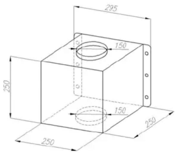
IKKE ALLE MODELLER – Dersom kjøkkenventilatoren som skal monteres er av typen med en eksternt plassert motor, må denne veiledning følges:
3. Elektrisk tilkobling
natural_image
Diagram showing a 3D mesh structure and its cross-section with a labeled circle (6), no text or symbols present.2.2. Kullfilter/resirkulering
natural_image
Technical line drawing of a mechanical device with circular components and a handle (no text or symbols)2.4. Rengjøring
natural_image
Symbol of a recycling bin with crossed lines and a blank rectangular base (no text or symbols)| III Tekniska data | ||
| Modell | ||
| FIRENZE P 60 ECO | FIRENZE P 80 ECO | |
| Spänning AC 230V 50Hz | ||
| Motorer | 1 | |
| Belysning | LED | |
| Antal fettfilter 1 | ||
| Sugstyrkor 3 + i | ||
| Bredd [cm] 60 80 | ||
| Djup [cm] 47 | ||
| Höjd [cm] 91-137 | ||
| Luftuttag [ø mm] 150 | ||
| Kapacitet [m 3/h] 308-512 (599) 341-551 (638) | ||
| Energiklass | A+ | |
| Ljudnivå [dBA] 48-58 49-59 | ||
| Version Extraktion eller recirkulerande | ||
| Finish | Rostfrit stål / glas | |
IV. Installation
2. Montering (extern motor)

3. Elektrisk anslutning
natural_image
Technical line drawing of a mechanical device with circular ports and a handle (no text or symbols)2.4. Rengöring
Waste Electrical and Electronic Equipment (WEEE).
| CONTENTS | |
| I. Advice and instructions | |
| II. Components | |
| III. Technical data | |
| IV. Installation | |
| 1. Mounting (built-in motor) | |
| 2. Mounting (external motor) | |
| 3. Electrical wiring | |
| 4. Use | |
| 4.1. Connecting to vent duct | |
| 4.2. Connecting the filtering version | |
| 4.3 Levels | |
| V. Operation and maintenance | |
| 1.Operation | |
| 1.1. Control panel | |
| 1.2. features | |
| 2. maintenance | |
| 2.1. Metal grease filter | |
| 2.2. Charcoal filter / recirculation | |
| 2.3. Lighting | |
| 2.4. Cleaning | |
Closely follow the instructions set out in this manual.
All responsibility, for any eventual inconveniences, damages or fires caused by not complying with the instructions in this manual, is declined.
The hood can look different to that illustrated in the drawings in this booklet. The instructions for use, maintenance and installation, however, remain the same.
I. Advice and instructions
- All responsibility, for any eventual inconveniences, damages or fires caused by not complying with the instructions in this manual, is declined.
- The mains power supply must correspond to the rating indicated on the plate situated inside the hood. If provided with a plug connect the hood to a socket in compliance with current regulations and positioned in an accessible area, after installation. If it not fitted with a plug (direct mains connection) or if the plug is not located in an accessible area, after installation, apply a double pole switch in accordance with standards which assures the complete disconnection of the mains under conditions relating to over-current category III, in accordance with installation instructions.
- Warning! Before re-connecting the hood circuit to the mains supply and checking the efficient function, always check that the mains cable is correctly assembled. The hood is provided with a special power cable; if the cable is damaged, request a new one from Technical Service.
- The premises where the appliance is installed must be sufficiently ventilated, when the kitchen hood is used together with other gas combustion devices or other fuels.
- With regards to the technical and safety measures to be adopted for fume discharging it is important to closely follow the regulations provided by the local authorities. The air must not be discharged into a flue that is used for exhausting fumes from appliance burning gas or other fuels.
-
This appliance is intended to be used in household and similar application
-
In this case the fumes are conveyed outside of the building by means of a special pipe connected with the connection ring located on top of the hood.
-
The minimum distance between the supporting surface for the cooking equipment on the hob and the lowest part of the range hood must be not less than 400-450 mm from electric cookers and 550 mm from gas or mixed cookers. If the instructions for installation for the gas hob specify a greater distance, this must be adhered to.

-
Attention! The exhausting pipe is not supplied and must be purchased apart.
-
Diameter of the exhausting pipe must be equal to that of the connection ring.
-
The aspirated air will be degreased and deodorised before being fed back into the room.
-
In order to use the hood in this version, you have to install a system of additional filtering based on activated charcoal.
II. Components
The Cooker hood consists of the following components (figur 1)
- The hood A,
- Upper C, and lower chimney B,
- Wallbracket F for upper chimney C
- Circulation plate E for the airflow in recirculation mode

| III Technical data | ||
| Model | ||
| FIRENZE P 60 ECO | FIRENZE P 80 ECO | |
| Voltage AC 230V 50Hz | ||
| Motors | 1 | |
| Lighting | LED | |
| Number of metal filters 1 | ||
| Suction 3 + i | ||
| Width [cm] 60 80 | ||
| Depth [cm] 47 | ||
| Hight [cm] 91-137 | ||
| Outlet [ø mm] 150 | ||
| Capacity [m 3/h] 308-512 (599) 341-551 (638) | ||
| Energyklass | A+ | |
| Noise [dBA] 48-58 49-59 | ||
| Version | Ventilation | |
| Finish | Stainless steel / glass | |
IV. Installation
It is recommended that the hood installation is done by authorized personnel and that are 2 to do the job.
For mounting the cooker hood the following steps will guide you:
- Mark drill holes on the wall
- Mark the minimum distance between hob and cooker hood
- Drill holes in the wall and insert dowels, G og H (fig. 3)
- Now mount the hood, A (fig. 1)
- Now connect the hood to the exhaust pipe
- Connect the cooker hood to the main supply
- Install wall brackets F (fig. 1) in the right position
- Mount the chimney parts B og C (fig. 1)
The cooker hood is opened by lifting the lower plate with two hands where the lights are placed. The extraction hood has a gas arm, which carries the weight of the glass front after opening. It is necessary to open the front glass to clean the grease filter and replacing coal / recirculation filter (in recirculation mode).
Before use, it is normal to close the front again. However, it can be left open during operation.
1. Mounting (built-in motor)
- Mark a vertical line on the wall, showing the center of the hob.
- The distance between the holes and the hob must be calculated so that the lower part of the assembled hood is placed at least 400-450 mm above electric hob and 550 mm above gas burner. Mark the location of mounting screws. Located 370 mm from the lower part of the hood.
- Drill the marked holes with a drill having a diameter corresponding to the fitting plugs. (Fig. 3) G and H. Set the wall plugs in the holes and screw the screws to the wall.
- Place the cooker hood on the screws.
- If the cooker hood is used in the version with ducted to the outside, mounted exhaust pipe now.
- (NB: For filter version) now mount the plate for regulation of air F together with the wall bracket. The module F are intended to guide the air through the recirculation air outlets in the upper portion of the upper stack module. Use the same mounting screws.
- Mark the appropriate height for the bracket for the chimney portion F (fig. 1).
- Now push the chimneyparts (B og C) into place in the appropriate height (fig. 1)
- Attach the upper chimney to the bracket F, fig. 1
- Connect to the main supply

2. Mounting (external motor)
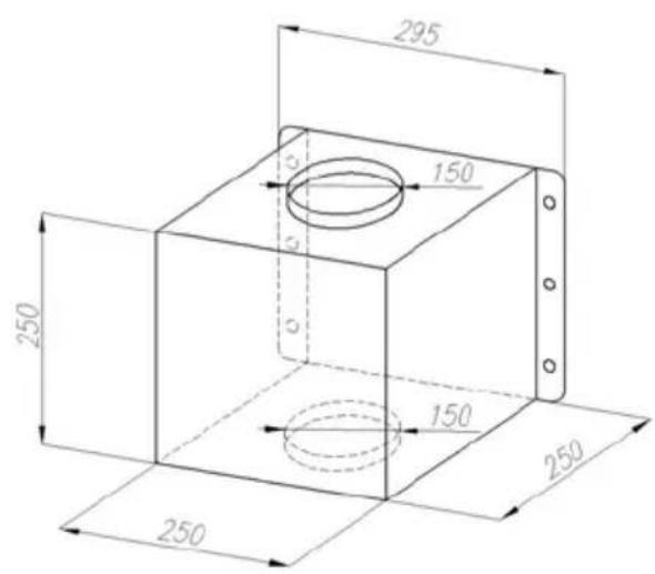
NOT ALL MODELS - Is the hood for external located motor, perform the following:
- Mark a vertical line on the wall, showing the center of the hob.
- The distance between the holes and the hob must be calculated so that the lower part of the assembled hood is placed at least 400-450 mm above electric hob and 550 mm above gas burner. Mark the location of mounting screws. Located 370 mm from the lower part of the hood.
- Drill the marked holes with a drill having a diameter corresponding to the fitting plugs. (Fig. 3) G and H. Set the wall plugs in the holes and screw the screws to the wall.
- Place the cooker hood on the screws.
- If the cooker hood is used in the version with ducted to the outside, mounted exhaust pipe now.
- Place the motor box S, where it is desired, for example. in the attic above the kitchen. Mount the motor box.
- Connect the hood to the motorbox with ∅ 150 ventilation duct R.
- Set the motor power cable and power cable together.
- Connect the motor box S for ventilation duct.
- Mark the appropriate height for the bracket for the chimney portion F (fig. 1).
- Now push the chimneyparts (B og C) into place in the appropriate height (fig. 1)
- Attach the upper chimney to the bracket F, fig. 1
- Connect to the main supply

3. Electric wiring
The electric wiring must be performed by a specialised electrician fully respecting current standards and legislation in force. Check that the power supply corresponds to the voltage requested by the hood, which is given on the silver label stuck inside the hood.
4. Use
4.1 Connecting to vent duct
The air is lead to the outside via. a vent pipe attached to the connection flange.
The cooker hood is connected to a vent pipe and the vent hole in the wall, which must have a diameter that fits the air suction.
If the pipe and the hole has a smaller diameter, exhaust capacity will be impaired and the noise increases significantly. The manufacturer disclaims any liability in connection.
a) Use a tube as short as possible.
b) Use a tube that has as few curves as possible (max. Angle of the curve: 90°).
c) Avoid drastic changes in pipe cross-section.
d) Use of a pipe as smooth an inner surface as possible.
e) The tube materials must be approved according to the rules.
4.2 Connecting to filtering version
When the hood is installed to operate with recirculation, the air is degreased and the odor is removed before air being returned back to the room through the openings in the chimney. To use the hood in this mode, install an additional filtration system based on active carbon.
In addition, it is recommended to mount the plate E (fig. 1) for guiding the air flow.
4.3 Powerlevels
The cooker hood has 4 fan speeds. Use the highest speed at high vapor concentration in the kitchen. It is recommended that you turn on the exhaust 5-
10 minutes before the start of cooking, and the exhaust is left on for at least about 15 minutes after cooking.
V Operation and maintenance
1. Betjening
1.1 Betjeningspanel
NOTE: TIMER - Setting must be completed within 20 seconds, otherwise the hood will automatically return to normal operation.
In case of power failure or crash, it may happen that the hood no longer perceives commands from the keyboard. In that case you have to disconnect the unit from the power supply and then reconnected to a cold start.
2. Maintenance
The hood must be regularly cleaned on both the inside and outside. At least once a month.
2.1 Metal-greace filters
The metal-greace filters retains grease particles generated during cooking of food.
Clean the grease filter(s) when necessary to maintain a good grease filter efficiency – at least once every 14 days (or when the filter saturation indication system indicates this necessity).
Use non aggressive detergents, either by hand or in the dishwasher, which must be set to a low temperature and a short cycle. When washed in a dishwasher, the grease filter may discolour slightly, but this does not affect its filtering capacity.
To remove the grease filter, pull the spring release handle.

natural_image
Diagram showing two geometric shapes: a shaded parallelogram labeled 'A' and a cross-sectional view with a container labeled 'W', both without any text or symbols.2.2. Charcoal filter / recirculation
It absorbs unpleasant odours caused by cooking.
The charcoal filter can be washed once every two months (or when the filter saturation indication system – if envisaged on the model in possession – indicates this necessity) using hot water and a suitable detergent, or in a dishwasher at 65°C
If the dishwasher is used, select the full cycle function and leave dishes out.
Eliminate excess water without damaging the filter, then put it in the oven for 10 minutes at 100irc C to dry completely.
Replace the mattress every 3 years and when the cloth is damaged.
Montering
a) Open the front panel.
b) Remove the metal filters.
c) Replace the carbon filter fixed inside the grease filter.
d) Attach the metal filters again.
2.3. Lighting
LED bulb replacement
- Switch off the power to the canopy hood and allow the bulb to cool.
- Use a small bladed screwdriver to pop out the light assembly, taking care not to damage the surrounding material.
- Unplug the Assembly from the wiring.
- Plug in the new assembly.
- Push the light assembly back into place.

natural_image
Line drawing of a mechanical switch or bracket with mounting holes and a handle (no text or symbols)2.4. Cleaning
The hood must be regularly cleaned on both the inside and outside (at least once a month). Clean using ONLY the cloth dampened with neutral liquid detergent.
DO NOT CLEAN WITH TOOLS OR INSTRUMENTS.
Do not use abrasive products. DO NOT USE ALCOHOL!
Failure to follow the instructions provided regarding the cleaning of the hood and filters will lead to the risk of fires.
Before any cleaning or maintenance operation, disconnect hood from the mains by removing the plug or disconnecting the mains electrical supply.
- Clean the filters when necessary – at least once a month
- Clean the cooker hood using a cloth dampened with neutral liquid detergent.
By regularly cleaned DO NOT USE:
a) wet cloth or sponge and running water
b) solvents or alcohol, which can make lacquered surfaces matt
c) caustics, especially when cleaning stainless steel elements
d) hard, coarse material
DISPOSAL
This appliance is marked according to the European directive 2012/19/EC on Waste Electrical and Electronic Equipment (WEEE). By ensuring this product is disposed of correctly, you will help prevent potential negative consequences for the environment and human health, which could otherwise be caused by inappropriate waste handling of this product.

The symbol on the product, or on the documents accompanying the product, indicates that this appliance may not be treated as household waste. Instead it should be taken to the appropriate collection point for the recycling of electrical and electronic equipment. Disposal must be carried out in accordance with local environmental regulations for waste disposal.
For further detailed information regarding the process, collection and recycling of this product, please contact the appropriate department of your local authorities or the local department for household waste or the shop where you purchased this product.
Made in EU



natural_image
Symbol of a trash bin with crossed lines indicating no waste or discharge, and a solid black rectangle below (no text or labels)
3. Sähkökytkennät
natural_image
Line drawing of a door handle with circular and rectangular components (no text or symbols)2.4. Puhdistus
Failure to follow the instructions provided regarding the cleaning of the hood and filters will lead to the risk of fires.
Tärkeää:
natural_image
Symbol of a waste bin with crossed lines and a blank rectangular block below (no text or labels)



- DANSK
- INDHOLD
- SUOMI
- SISÄLTÖ
- Installation
- Montering (ekstern motor)
- Elektrisk tilslutning
- Funktioner
- Timer
- Kulfilter/recirkulation
- Lys
- Rengøring
- Elektrisk tilkobling
- Kullfilter/resirkulering
- Rengjøring
- Montering (extern motor)
- Elektrisk anslutning
- Rengöring
- Closely follow the instructions set out in this manual.
- Advice and instructions
- Components
- Mounting (built-in motor)
- Mounting (external motor)
- Electric wiring
- Use
- Connecting to vent duct
- Connecting to filtering version
- Powerlevels
- V Operation and maintenance
- Betjening
- Betjeningspanel
- NOTE: TIMER - Setting must be completed within 20 seconds, otherwise the hood will automatically return to normal operation.
- Maintenance
- Metal-greace filters
- The metal-greace filters retains grease particles generated during cooking of food.
- Charcoal filter / recirculation
- It absorbs unpleasant odours caused by cooking.
- Montering
- Lighting
- LED bulb replacement
- Cleaning
- DO NOT CLEAN WITH TOOLS OR INSTRUMENTS.
- DISPOSAL
- Sähkökytkennät
- Puhdistus
- Tärkeää:
Brand : EICO
Model : Firenze 60 W EM ECO
Category : Range hood