
Phantom Shift 80 N F - Range hood EICO - Free user manual and instructions
Find the device manual for free Phantom Shift 80 N F EICO in PDF.

| Product Type | Range hood with integrated induction cooktop (cooktop extractor) |
| Dimensions (with frame) | 206 x 786 x 520 mm (H x W x D) |
| Power Supply | 220-240 V (single phase) or 380-415 V (two phases), 50/60 Hz |
| Max Power Consumption | 7.4 kW |
| Fuse Protection | 1 x 32 A (single phase) / 2 x 16 A (two phases) |
| Cooking Zones | 2 induction zones (210 x 190 mm each), 2100 W (standard), 3000 W (booster), 3700 W (bridge) |
| Fan Modes | Automatic (speed adjusts to cooking zone power), manual (9 levels), after-run (5 min at level 1), timer |
| Filter Types | Grease filters (metal, dishwasher safe), activated carbon filters (only for recirculation mode) |
| Filter Indicators | Grease filter and carbon filter state indicators with reset function |
| Safety Features | Child lock, key lock, automatic switch-off, overheating protection, pan detection, residual heat indicator |
| Additional Functions | Bridge, warming, pause, recall, fast cooking (booster), heat-up automatic, timer (up to 9h59min), alarm, power management |
| Cooktop Material | Glass ceramic |
| Cleaning | Glass ceramic with standard cleaners; grease filters in dishwasher; carbon filters regenerate in oven at 180°C for 1 hour |
| Installation Modes | Exhaust air or recirculation (requires carbon filters) |
| Energy Consumption (cooktop) | 187 Wh/kg (average) |
| Minimum Pan Diameter | 110 mm (single zone), 230 mm (bridge) |
Frequently Asked Questions - Phantom Shift 80 N F EICO
User questions about Phantom Shift 80 N F EICO
0 question about this device. Answer the ones you know or ask your own.
Ask a new question about this device
Download the instructions for your Range hood in PDF format for free! Find your manual Phantom Shift 80 N F - EICO and take your electronic device back in hand. On this page are published all the documents necessary for the use of your device. Phantom Shift 80 N F by EICO.
USER MANUAL Phantom Shift 80 N F EICO
INSTRUCTIONS ON MOUNTING AND USE
DK
MONTERINGS- OG BRUGSVEJLEDNING

natural_image
Illustration of two gloves with textured soles (no text or symbols)EN Always wear work gloves for all installation and maintenance operations
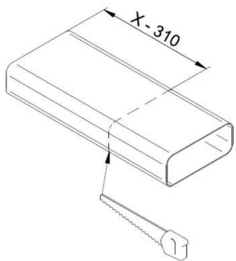
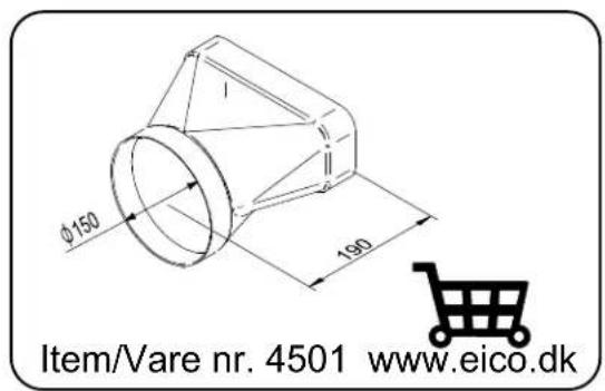
The following special tools are required to correctly install the cooktop:
natural_image
Technical line drawing of a mechanical assembly with no visible text or symbols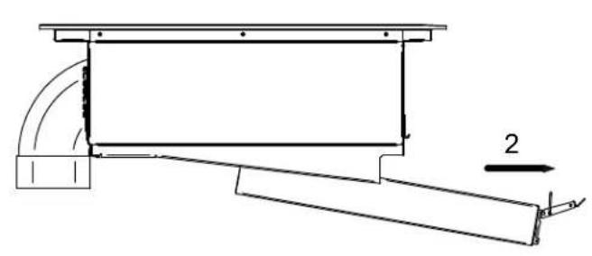
natural_image
Technical line drawing of a mechanical assembly with curved components and a labeled dimension (no text or symbols)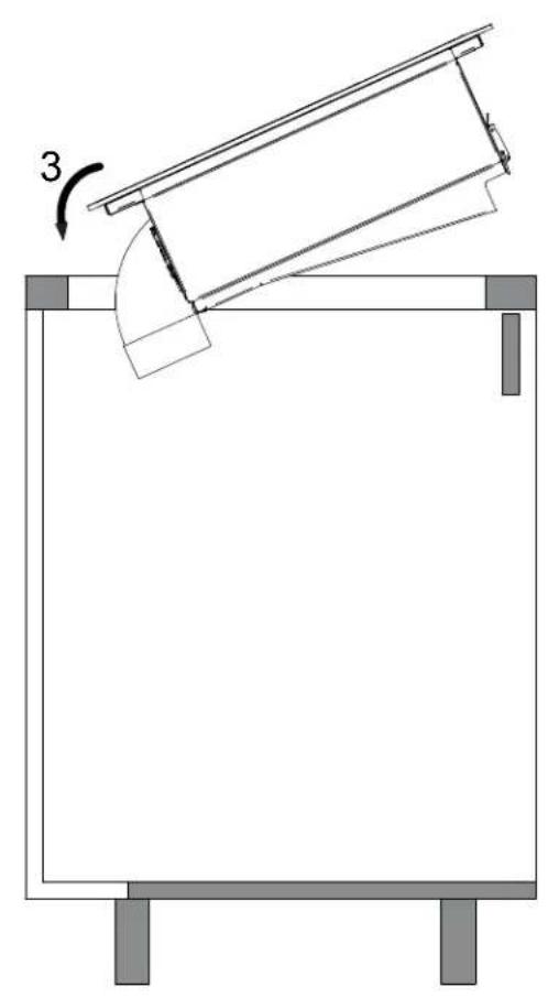
natural_image
Diagram of a mechanical setup with a tilted rectangular frame and a curved component, labeled with number 3 (no text or symbols present)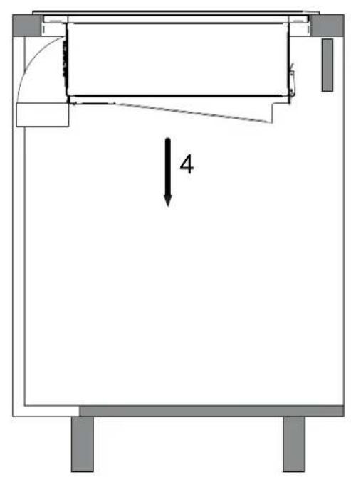
Installation A

A1

A3
natural_image
Pure technical line drawing of a mechanical assembly or frame structure without any text, numbers, or symbolsA1 8
A2 9
A3 11
natural_image
Technical line drawing of a mechanical or architectural component with dimension lines and no visible text or symbols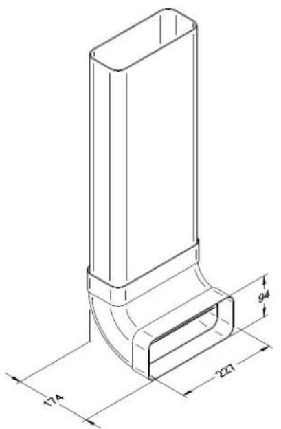
natural_image
Technical line drawing of a mechanical component with a cylindrical end and flange (no text or symbols)Installation A1
natural_image
Technical line drawing of a mechanical device with a curved pipe and rotation arrow (no text or symbols)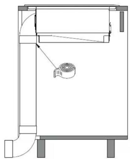
natural_image
Technical line drawing of a mechanical device with no visible text or symbolsInstallation A2

natural_image
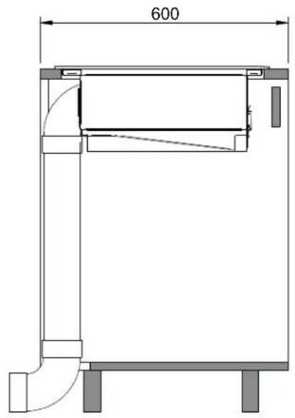
Technical line drawing of a mechanical assembly with exploded view and internal components (no text or symbols)


natural_image
Technical line drawing of a mechanical assembly with exploded view and internal components (no text or symbols)Installation A3

natural_image
Technical line drawing of a mechanical assembly with exploded view and internal components (no text or symbols)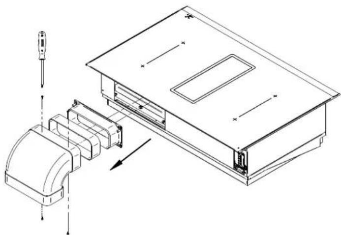
natural_image
Technical line drawing of a device assembly with exploded view and internal components (no text or symbols)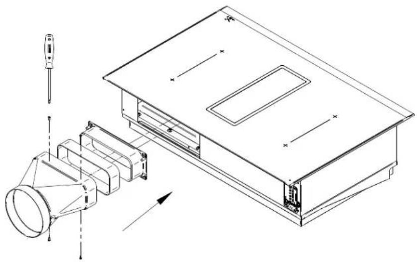
natural_image
Technical line drawing of an electronic device with exploded view and internal components (no text or symbols)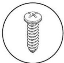
natural_image
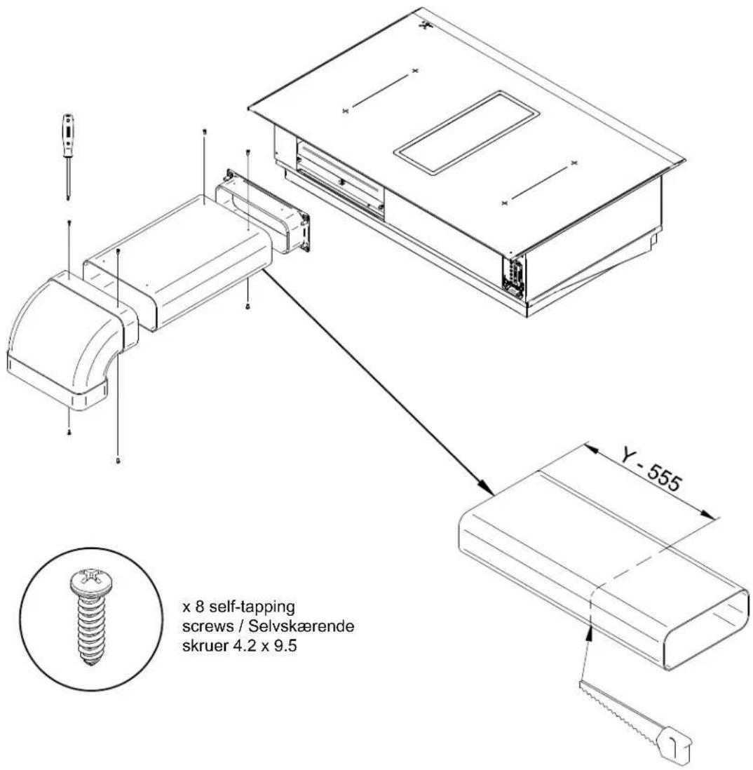
Simple line drawing of a screw inside a circle (no text or symbols)x 4 self-tapping
natural_image
Technical line drawing of a device rear panel with internal components and a close-up view of the front panel (no text or symbols)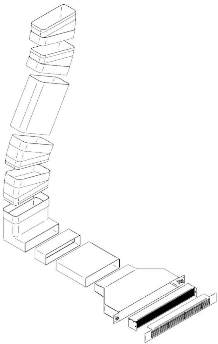
natural_image
Exploded view diagram of a multi-layered storage unit structure (no text or symbols)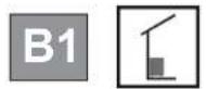
natural_image
Isometric technical line drawing of a mechanical or architectural component inside a transparent enclosure (no text or symbols)

natural_image
Isometric line drawing of a building interior with stairs and structural elements (no text or symbols)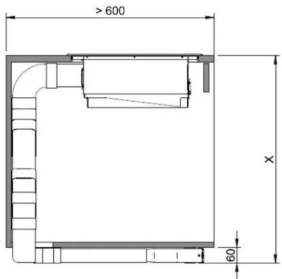
natural_image
Isometric line drawing of a mechanical assembly inside a transparent cube, showing internal components and alignment lines (no text or symbols)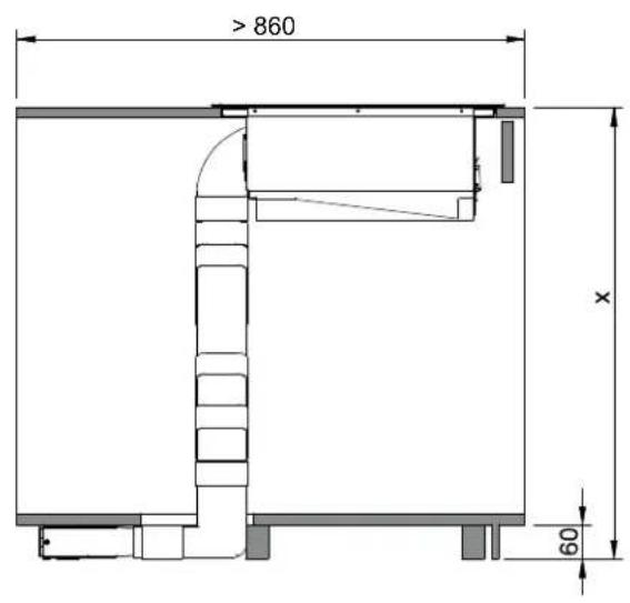

natural_image
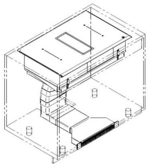
Isometric technical line drawing of a mechanical assembly with no visible text or symbols| B1 | 19 |
| B2 | 20 |
| B3 | 22 |
| B4 | 23 |
natural_image
Diagram of a mechanical or structural assembly with layered components and directional arrows, no text or symbols present.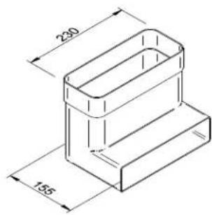
natural_image
Technical line drawing of a mechanical assembly with a curved component and rotational motion indicator (no text or symbols)
natural_image
Architectural floor plan showing room layouts and a central mechanical component (no text or labels)
natural_image
Technical drawing of a mechanical component with dimension标注 (450), showing internal curved structure and mounting brackets (no text or symbols beyond measurement)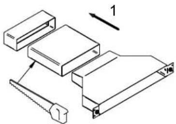
natural_image
Technical line drawing of a mechanical assembly with a labeled component (no text or symbols present)
natural_image
Architectural floor plan showing room layout and stairwell placement (no text or labels)
natural_image
Architectural floor plan diagram showing room layout and a numbered component (no text or labels)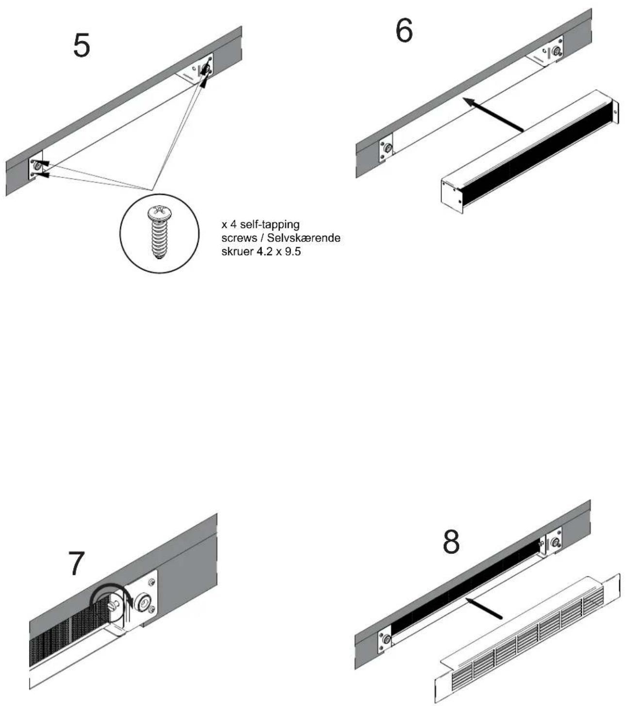
x 4 self-tapping
screws / Selvskærende
skruer 4.2 x 9.5
Installation B1
Installation B2
natural_image
Technical line drawing of a mechanical assembly with exploded view and close-up detail (no text or symbols)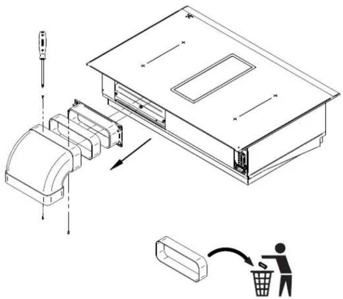
natural_image
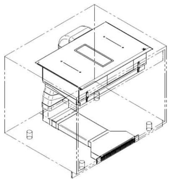
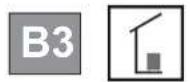
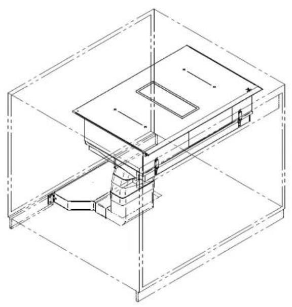
Technical line drawing of a mechanical assembly with exploded view and internal components (no text or symbols)Installation B3
Installation B4
natural_image
Isometric technical line drawing of a mechanical assembly inside a rectangular housing (no text or symbols)2.1 For your information p. 25
2.2 Intended use p. 25
2.3 Explanation for symbols and indications p. 25
3 Safety instructions and warnings
3.1 For connection and operations p. 26
3.2 General information about the hob p. 26
3.3 For persons p. 27
4 Appliance description
4.1 System description p. 28
4.2 Operating panel p. 29
4.3 How the cooktop extractor works p. 30
4.4 How the induction cooktop works p. 30
4.5 The induction hob p. 31
4.6 Technical informations p. 31
5 Operation
5.1 Appropriate cookware p. 32
5.2 Power regulation p. 33
5.3 Energy saving tips p. 33
5.4 Hob control p. 33
5.5 Slide control p. 33
5.6 Turn the hob on p. 33
5.7 Turn cooking zones on p. 34
5.8 Turn cooking zones off p. 34
5.9 Turn the hob off p. 34
5.10 Key-lock p. 34
5.11 Child-lock p. 34
5.12 Pause p. 35
5.13 Recall p. 35
5.14 Remaining heat indicator p. 35
5.15 Fast cooking p. 35
5.16 Power management system p. 36
5.17 Heat-up automatic p. 36
5.18 Bridge p. 36
5.19 Warming p. 37
5.20 Safety switch-off p. 37
5.21 Protection from overheating p. 37
5.22 Timer p. 37
5.23 Alarm p. 39
5.24 Manual / Automatic fan p. 39
5.25 Fan after-run p. 39
5.26 Fan timer p. 39
5.27 Fan pause and recall p. 39
5.28 Grease filter state indication p. 39
5.29 Carbon filter state indication (recirculation mode only) p. 40
5.30 Power limitation setting p. 40
6 Cleaning and care
6.1 Glass ceramic hob p. 41
6.2 Specific soiling p. 41
6.3 Air inlet flap and grease filters p. 42
6.4 Remove liquids from the appliance p. 42
6.5 Regenerating and replacing the activated carbon filters (only in recirculation mode) p. 43
7 Troubleshooting
8 Decommissioning and disposal
8.1 Decommissioning p. 46
8.2 Disassembly p. 46
8.3 Disposing of the packaging p. 46
8.4 Disposing of old appliance p. 46
General
2.1 For your information...
Please read this manual carefully before using your appliance. It contains important safety advice; it explains how to use and look after your appliance so that it will provide you with many years of reliable service.
Should a fault arise, please first consult the section on "Troubleshooting". You can often rectify minor problems yourself, thus saving unnecessary service costs.
Please keep this manual in a safe place and pass it on to new owners for their information and safety.
Assembly and installation may only be carried out by trained specialists and taking into account the applicable laws, regulations and standards. All safety and warning information as well as the handling instructions in the enclosed documents must be observed.
2.2 Intended use
The appliance is to be used solely for preparing food in the home or in other environments. Similar environments:
- Use in shops, offices and other similar working environments.
- Use in agricultural enterprises.
- Use by customers in hotels, motels and other typical living environments.
- Use in breakfast buffets.
- It may not be used for any other purpose and may only be used under supervision.
2.3 Explanation for symbols and indications
The following appliance was produced according to state of the art technology. Machines nevertheless give rise to risks which cannot be constructively avoided.
In order to guarantee sufficient safety for the use, safety instructions are also given. These instructions are marked by way of the highlighted texts which follow.
Sufficient safety in operation will only be guaranteed when these instructions are observed.
The designated text passages have different meanings:

DANGER
Note indicating an imminent threat which may result in death or very serious injuries.
CAUTION
Note that indicating a potentially dangerous situation which may result in death or very serious injuries
IMPORTANT
Note indicating a dangerous situation which may result in minor injuries or damage to the appliance.
NOTE
Note to be observed in order to make handling the appliance easier.
WARNING OF ELECTRICAL ENERGY! RISK OF FATAL INJURY!
Live components have been installed near this symbol. Covers bearing this sign may only be removed by a certified skilled electrician.
CAUTION! HOT SURFACES!
This symbol has been applied to surfaces which get hot. There is a risk of serious burning or scalding. The surfaces may also be hot after the appliance has been switched off.
OBSERVE REGULATIONS FOR HANDLING ELECTROSTATICALLY SENSITIVE COMPONENTS AND MODULES (ESDS)
Electrostatically endangered components and modules are located behind covers bearing the adjacent symbol. Never touch plug connections, strip conductors or component pins. Only qualified staff members who are familiar with ESDs are authorised to carry out technical intervention work.
3 Safety Instructions and Warnings
3.1 For connection and operation

- The appliances are constructed in accordance with the relevant safety regulations.
- Connecting the appliances to the mains and repairing and servicing the appliances may only be carried out by a qualified electrician according to currently-valid safety regulations. For your own safety, do not allow anyone other than a qualified service technician to install service or repair the product.
- If the mains supply cable of this appliance is damaged, it must be replaced by the manufacturer, the Customer Service of the manufacturer or by another qualified person to avoid danger.
- The appliance may not be operated with an external timer or an external tele control system.
3.2 General information about the hob


- Never allow the induction hob to operate unattended, as the high power setting results in extremely fast reactions.
- When cooking, pay attention to the heat-up speed of the cooking zones. Avoid boiling the pots dry as there is a risk of the pots overheating!
- Do not place empty pots and pans on cooking zones which have been switched on.
• Take care when using simmering pans as simmering water may dry up unnoticed, resulting in damage to the pot and to the hob for which no liability will be assumed. - It is essential that after using a cooking zone you switch it off with the respective minus key and not just with the pan recognition device.
• Overheated fats and oils may spontaneously ignite. Always supervise the preparation of food with fats and oils. Never extinguish ignited fats and oils with water! Switch the appliance off and then carefully cover the flame, for example with a lid or an extinguisher blanket.
• The glass ceramic surface of the hob is extremely robust. You should, however, avoid dropping hard objects onto the glass ceramic hob. Sharp objects which fall onto your hob might break it. - There is a risk of electric shocks if the glass ceramic hob develops fractures, cracks, tears or damage of any other kind. Immediately switch off the appliance. Disconnect the fuse immediately and call Customer Service.
- If the hob cannot be switched off due to a defect in the sensor control immediately disconnect your appliance and call Customer Service.
- Take care when working with home appliances! Connection cables must not come into contact with hot cooking zones.
- Risk of fire: never store items on the hob.
- The glass ceramic hob should not be used as a storage area.
- Do not put aluminium foil or plastic onto the cooking zones. Keep everything which could melt, such as plastics, foil and in particular sugar and sugary foods away from hot cooking zones. Use a special glass scraper to immediately remove any sugar from the ceramic hob (when it is still hot) in order to avoid damaging the hob.
- Metal items (pots and pans, cutlery, etc.) must never be put down on the induction hob since they may become hot. Risk of burning!
- Do not place combustible, inflammable or heat deformable objects directly underneath the hob.
- Metal items worn on your body may become hot in the immediate vicinity of the induction hob. Caution! Risk of burns! Non-magnetisable objects (e.g. gold or silver rings) are not affected.
- Never use the cooking zones to heat up unopened tins of food or packaging made of material compounds. The power supply may cause them to burst!
- Keep the sensor keys clean since the appliance may consider dirt to be finger contact. Never put anything (pans, tea towels etc.) onto the sensor keys!
- If food boils over onto the sensor keys, we advise you to activate the OFF key.
- Hot pans and pots should not cover resp. be moved too close to the sensor keys, since this will cause the appliance to switch off automatically.


- Place the pan as close to the centre of the cooking zone as possible.
- Whenever possible, use the back cooking zones for large pans so that the sensor keys are not heated up too much (touch control overheating; error message E2, touch control cut off).
- Activate the childproof lock if there are any pets in the home, which could make contact with the hob.
- The induction hob may not be used when pyrolysis operation is taking place in a built-in oven.
- Do not place pots on the air inlet flap.
- Never clean the glass ceramic hob with a steam cleaner or similar appliance!
- Make sure there are no items (e.g. cleaning cloths) right next to the hob extractor. They could be sucked in by the air current. Liquids and small items must always be kept away from the appliance.
- Do not operate the appliance without grease filters.
- Filters with too much fat deposit cause fire hazard!
- Constant supervision is essential when deep-frying; flambéing is not permitted.
- A sufficient supply of inlet air must be provided when operating wood, coal, gas or oil heaters requiring a chimney. The permissible negative pressure which results from the hood in the location of the heaters requiring a chimney may not exceed 4 Pa (0.04 mbar) as this results in a risk of poisoning.
3.3 For persons

• These appliances may be used by children aged 8 years and over and by persons with physical, sensory or mental impairments or by persons who lack experience and/or knowhow, provided they are supervised or have been instructed in the safe use of the appliance and have understood the risks relating to the appliance. Children may not play with the appliance. Cleaning and maintenance by the user may only be carried out by children when they are supervised.
- The surfaces of the heating and cooking zones become hot during use. Keep small children away at all times.
- Only hob protective grids and hob covers produced by the hob manufacturer or someone authorised by the manufacturer in the instructions for use may be used. The use of unsuitable hob protective grids and hob covers may result in accidents.
- Persons with cardiac pacemakers or implanted insulin pumps must make sure that their implants are not affected by the induction hob (the frequency range of the induction hob is 20-50 kHz).
• To move the pots from a cooking zone to another do not drag them on the glass surface: risk of scratching the glass or hitting the air inlet flap!

4 Appliance description
Observe all safety and warning information during operation (see Safety chapter).
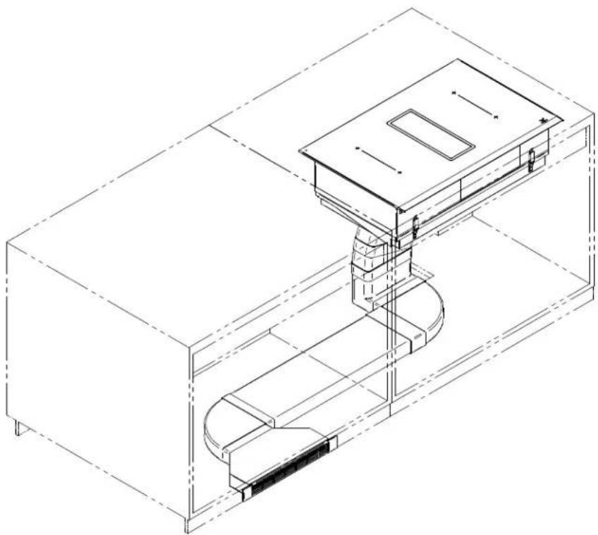
4.1 System description
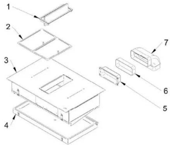
Aspiration system
Recirculation system
- Inlet opening – air inlet turnable flap
- Grease filters
- Cooktop
- Water collector
- Canalization entrance
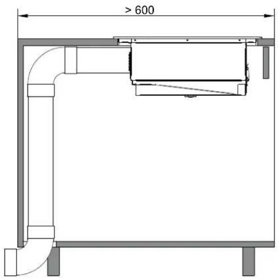
- Horizontal ducting
-
90° bend duct
-
Vertical ducting
- Vertical canalization for recirculation
- Plastic adapter
- Horizontal ducting
- Filters box
- Activated carbon filters
- Recirculation grid
4.2 Operating panel
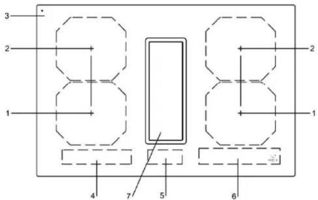

- Front induction cooking zone
- Rear induction cooking zone
- Glass ceramic hob
- Left cooking zones touch control
- Fan touch control
- Right cooking zones touch control
- Fan
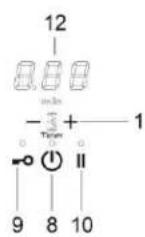
- ON/OFF key
- Lock key
- Pause key
- Minus key / Plus key timer
- Timer display
-
Cooking zone power level display
-
Cooking zone timer
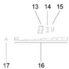
- Bridge function display
- Cooking zone slider control display
- Warming function display
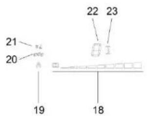
- Fan slider control display
- Fan automatic mode indication
- Grease filter state indication
- Carbon filter state indication (only active in recirculation mode)
- Fan power level display
- Fan timer

NOTE
Most of the keys shown here will only become visible when the hob has been switched on.
4.3 How the cooktop extractor works
Depending on the model you purchased, the cooktop extractor can be operated as an exhaust air or a recirculating air version.

Exhaust air mode
The air suctioned away is purified by the grease filter and expelled into the open air via a duct system. The exhaust air must not be expelled into:
- a smoke or exhaust gas flue that is in operation
- a shaft used for the aeration of rooms where fireplaces are installed.
If the exhaust air is to be directed into a smoke or exhaust gas flue that is not in use, the installation must be checked and approved by the responsible heating engineer.

Recirculation mode
The air suctioned away is purified by the grease filter and an activated charcoal filter and fed back into the room in which the appliance is installed. To prevent odours in recirculation mode, an odour filter must be used. For hygiene and health reasons, the activated charcoal filter must be replaced at the recommended intervals (see the Cleaning and maintenance chapter).
4.4 How the induction cooktop works
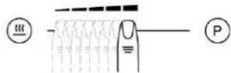
4.4.1 Slide control
The glass ceramic hob is operated with touch control sensor keys. The sensor keys are operated as follows: lightly touch a symbol on the surface of the ceramic glass plate. A buzzer will indicate when the controls have been operated correctly.
The touch control sensor key will then be indicated as "key".
What must be observed when operating sensor fields?
Your finger should not be placed flat onto the glass ceramic surface in order to avoid adjacent keys/sensor fields from reacting by mistake.
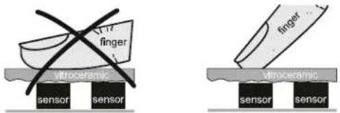
unsuitable right
Press the sensor field lightly or move your finger around
You can press the sensor field very lightly with your finger; when this is done the setting on the display (power level) will gradually change.
When you put your finger on the sensor field and then move it to the left or right, the display setting will change progressively.
The faster the movement, the faster the change in the display.
4.5 The induction hob
The hob is equipped with an induction cooking mode. Induction coils underneath the glass ceramic hob generate an electromagnetic alternating field which penetrates the glass ceramic and induces the heat-generating current in the pot base.
With an induction cooking zone the heat is no longer transferred from a heating element through the cooking pot into the food being cooked; instead the necessary heat is generated directly in the container by means of induction currents.
Advantages of the induction hob
- Energy-saving cooking through the direct transfer of energy to the pot (suitable pots/pans made of magnetisable material are required).
- Increased safety as the energy is only transferred when a pot is placed on the hob.
- Highly effective energy transfer between an induction cooking zone and the base of a pot.
- Rapid heat-up.
- The risk of burns is low as the cooking area is only heated through the pan base; food which boils over does not stick to the surface.
- Rapid, sensitive control of the energy supply.
4.6 Technical informations
| Two phases connection 380 - 415 V | |
| One phase connection 220 - 240 V | |
| Frequency 50 / 60 Hz | |
| Maximum power consumption 7.4 kW | |
| Fuse protection / One phase 1 x 32 A | |
| Fuse protection / Two phases 2 x 16 A | |
| Cooktop | |
| Material surface Glass ceramic | |
| Power levels 1 – 9, P | |
| Cooking zone size 210 x 190 mm | |
| Cooking zones power output | 2100 WP = 3000 WBridge = 3700 W |
| Cooktop energy consumption | |
| Cooking zone 210x190 | 187 Wh/kg |
| Total (average) | 187 Wh/kg |
| Hob dimensions | |
| Height / width / depth | 206 x 780 x 520 mm (without frame)206 x 786 x 520 mm (with frame) |
OPERATION EN
5 Operation
5.1 Appropriate cookware
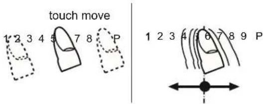
natural_image
Four identical line drawings of a cooking pot with handles and crossed handles, no text or symbols present.Induction hotplate will function perfectly only if appropriate pot is used.
- The pot should be in the middle of the hotplate during cooking.
- The appropriate pot is the one which enables induction, for example steel, enamel or steel alloy. Pots made from steel alloy with copper or aluminium bottom, or glass pots are inappropriate.
- If you use the pressure pot, keep it under close surveillance until proper pressure is obtained. Hotplate should first operate on maximum power, then follow the manufacturer's instructions.
When buying cookware, check if it bears the label "allows induction".
| COOKING ZONES ∅ MIN. PAN BOTTOM | |
| 210x190 mm (SINGLE) ∅ 110 mm | |
| 210x190 mm(BRIDGE) | ∅ 230 mm |

Note:
When Bridge function is selected, you can use the created zone in different ways, with one or two pots. If you use larger pots than the recommended maximum size, the heating time will be longer, because the heating will propagate from center to edges of the pot by conduction, in this case also the temperature will be very inhomogeneous.
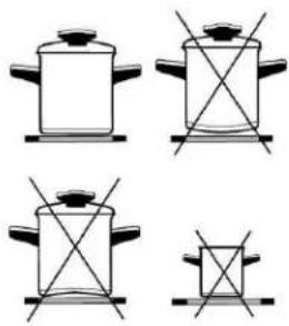
Magnet test
Use small magnet A to test if the dish bottom is magnetic. Only dishes where magnet sticks to the bottom are suitable.
Dish recognition
One of great advantages of the induction hotplate is dish recognition.
When the hotplate is on, the power indicator displays If you place the dish over that hotplate within the following 10 minutes, the hotplate recognizes the dish and turns on to the pre-set power value.
At the moment you remove the dish from the hotplate, power is suspended. If you place smaller dish upon the hotplate and it is recognized, the hotplate will only use the amount of energy required to heat the dish according to its size.
Hotplate may be damaged if:
• empty hop are heated up.
- you don't use the appropriate pots.
- you use clay dishes which leave scratches on the glass surface.
- you don't wipe the pot bottom.

The use of bad quality cookware or any adapter for non-magnetic cookware invalidates product warranty. In this case, the manufacturer cannot be held responsible for any damage caused to the appliance and / or objects closed to the same.
EN OPERATION
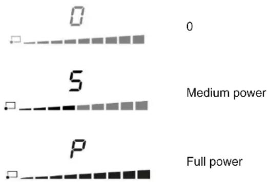
5.2 Power regulation
Heating power of the hotplates may be set at ten different levels.
The chart indicates illustrative use of each power setting.
| Power setting | Purpose |
| 0 | Off, using remaing heat |
| 1-2 | Maintaining warm food, slow simmer of smaller quantities |
| 3 | Slow simmer (continuation of cooking after a powerful start-up) |
| 4-5 | Slow cooking (continuation of larger quantities, roasting larger chunks) |
| 6 | Roasting, Browning |
| 7-8 | Roasting |
| 9 | Start of cooking, roasting |
| A | Automatic heat up |
| P | Especially powerful setting for extremely large quantities of food |
5.3 Energy saving tips
- When buying pots, be careful in selecting size: pot diameter usually refers to the top edge of the pot, which is often larger than the bottom;
- Steam-pressure pots, which use pressure in tightly sealed interior, are especially economic, and save both time and energy. Shorter cooking time leaves more vitamins in food;
- Always leave enough water in steam-pressure pots, otherwise it may result in overheating which may damage both the pot and the appliance;
• Always cover pots with lids of appropriate size; - Use such pot size to accommodate the quantity of food to be prepared.
5.4 Hob Control
- After turning the ceramic glass hob on all displays come on for a moment. The hob is ready for operation.
- The hob is fitted with electronic sensors which are switched on if you touch the relevant circle for at least one second.
• Each sensor activation is followed by a sound signal. - Avoid placing any objects on sensor surface (possible error signalization).
• Always keep the sensor surface clean.
5.5 Slide Control
5.6 Turn the hob on

- Press for at least one second.
• The hob is now active, and all cooking zone displays indicate - Now you need to select the next setting within 10 seconds, otherwise the hob switches off.
5.7 Turn cooking zones on
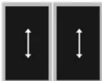
After turning the hob, within the next 10 seconds start one of the cooking zones. Set the power level 1 - P by touching below the slider LED display.
- At the first touch, the level is set according to the part of the slider that you touch. Upon the slider control, the LEDs light up, according to the level set.
- By sliding along the slider, the power level setting is changed. By sliding to the right, the level increasing, while sliding to the left decreases the level.
- When you move your finger away from the slider control, the cooking field starts to operate at the level set.
5.8 Turn cooking zones off
If a specific point of the slider control is pressed for at least 3 seconds, the automatic cooking is activated (see Automatic fast heating).
- Selected hotplate must be activated.
- By touching the slider sensor at the start, bring the power setting to Short beep confirms the OFF position.
5.9 Turn the hob off
• The hob is switched off by pressing
- The sound signal beeps and all indicators go off, except for those hotplates which are still hot and display the warning sign as an indication of the remaining heat.
5.10 Key-lock
By activating the key lock protection, you can stop the operation of the appliance and the use of hotplates.
Activation
• The cooktop must be turned on.
- Press =0 for approximately 1 second, the corresponding LED turns on above the key, the block is active.
. Safety lock prevents the activation of all sensors, except for and =0
- If the hob is switched off when the lock function is activated, it remains in memory until a new switch on of the hob.
- When set timers end their time, alarms can be switched off pressing or without need for unlocking the control.
Deactivation
The cooktop must be turned on
Press =0 for 1 second; after that, the unlocking is confirmed by a beep.
5.11 Child-Lock
This function can only be activated/deactivated after turning on the hob with and with all cooking zone at zero level.

Activation
- Press = and simultaneously for 3 seconds.
• Function is active and all displays show
- Hob control remains locked and switches automatically off after 10 sec.
The Child-Lock deactivates all keys except ⏻ Once activated electronic stays locked even if the control is switched off and on again.
Deactivation
- Within 10 sec. press =0 and simultaneously for 3 seconds.
EN OPERATION
5.12 Pause
The execution of the function is possible only if at least one cooking zone is on. In pause mode, the cooking process is suspended and the hob does not deliver power.
Activation
- Press || for at least 1 second, the corresponding LED turns on above the key and all displays show ||
While the Pause function is active
- Any Timer (also Alarm Timer) set before the pause will be stopped during the pause and continue when pause mode is quitted.
• Cooking zones are turned off. - A selected booster or heat up time automatic function is terminated.
- Residual heat calculation and maximum operation time limitations will not be interrupted and keep on working in the background.
- Functional LED's such as Timer, multi-zone, keep on glowing according to their status.
The pause mode can only be active for maximum 10 min.
Throughout the pause time, (1) can be used to switch the control off. In this case the pause mode is also deactivated.
Deactivation
- Press ||, the LEDs light up above the cursor of one of cooking zones.
- Within 10 seconds press and scroll from the left to the right on the slider cursor of the illuminated area. The LED above the pause key turns off and the condition before the pause mode is restored.
5.13 Recall
If the control was accidentally switched off through the main all settings can be restored using the recall function.
After switching the control off from the main switch the user has 6 seconds to switch the control on again and then another 6 seconds to press in order to recall the settings.
The recall function can only be used if at least one cooking zone was active (cooking level >0) independent from key lock.
5.14 Remaining heat indicator
Appliances also features remaining heat indicator. Hotplates are not heated directly, but through return heat radiating from the dish. As long as is on after the hotplate was switched off, the remaining heat may be used for warming up food or for melting.
Even when H disappears, the hotplate may still be hot.
5.15 Fast cooking
Be careful of burns!
Extra powerful setting may be additionally switched on for fast cooking. This extra power is used for heating large quantities of food.
After switching on, the extra power is activated for 5 minutes then automatically switches back on to the maximum normal level 9.
During the time extra power is activated, the power of other hotplates is limited. This is indicated on the power display by intermittently flashing the selected cooking level and limited power for a few seconds.
Activation
- Select the desired cooking zones and move the slider control to the extreme rights to activate the extra power P
• The extra power is active.
. The display shows P.
Premature deactivation
Press and scroll on the slider control of the desired zone, until you get to want to turn off the zone, or until the wanted cooking level.

5.16 Power management system
The Power Management system distributes power between the available cooking zones arranged in pairs (such as figures on the side), providing maximum power at a cooking zone and automatically reducing the power available to the other one. The display of the second cooking zone alternates, for a few seconds, the power of cooking chosen and the limited power.

In certain circumstances, the Extra powerful setting function may turn off automatically to protect the electronic components inside the hob.
5.17 Heat-up time automatic
This function preheats the burner on maximum power in order to bring it rapidly up to the required temperature. After a given time interval, the power level returns spontaneously to the established setting.
It may be switched on in any of the hotplates for all power settings except for setting "9" where power is set at maximum all the time.
Activation
• Automatic cooking mode is activated on any idle hotplate.
- Choose the required continuous cooking level and hold it for 3 seconds.
- The activated heat up time automatic will be d isplayed through alternating between A and the selected continuous cooking level on the display. As soon as the parboiling time is over, the preselected continuous cooking level is valid again.
- Once the time in the chart below expires, the function is switched off and R disappears. You can also switch the automatic cooking mode off anytime by modifying power level.
| Power setting | 1 | 2 | 3 | 4 | 5 | 6 | 7 | 8 |
| Max. power cooking time (seconds) | 40 | 72 | 120 | 176 | 256 | 432 | 120 | 192 |
5.18 Bridge
With the bridge function two separate cooking zones with the same diameter and equal power. The bridge function is available for cooking zones showing symbols:

Two cooking zones can be turned on at the same time and controlled with only one operation
Activation
- Whether the two zones are working at a different level, whether they are at level 0, simultaneously press anywhere on the slider controls of the zones.
- Now the two areas work together, the LEDs to the right of the corresponding displays turn on. The level is shown on the display of the control zone, in the meanwhile the controlled zone's display turns off.
- When this function is active, you can set the timer, the LED lights on near both displays of the zones.
- If in 10 uninterrupted minutes no cookware is detected on one of the two elements, the bridge function is automatically deactivated.
Deactivation
The end of the Function can be done by repeating the simultaneous selection of both cooking elements (the same as activation).
- If the function is deactivated while in operation, than both cooking elements go to level and can then be set again.
EN
OPERATION
5.19 Warming
The warming function is used to keep cooked food warm. Hence this function can also be used as melting or simmer function.
Activation
- Press of a cooking zone activates the "warming";
If is pressed a second time "warming" function ends.
5.20 Safety switch-off
Maximum continuous operation of a particular hotplate is limited, and the duration is displayed in the above chart. When the hotplate is switched off by the safety mechanism, the indicator displays symbols for H case there is any remaining heat left.
| Power setting Minutes lapse prior safety switch off | |
| Warming 120 | |
| 1 516 | |
| 2 402 | |
| 3 318 | |
| 4 258 | |
| 5 210 | |
| 6 138 | |
| 7 138 | |
| 8 108 | |
| 9 90 | |
| P 5 | |
Example:
Set the hotplate to power level 5 and leave it operate for some time. If you do not change the above setting, the safety mechanism will switch the hotplate off after 210 minutes.
5.21 Protection from overheating
Induction hotplate is also fitted with safety device against overheating which protects electronic parts from damages. This device operates on several levels. When temperature of the hotplate excessively rises, it switches on two-stage fan. If this is not enough, extra powerful heating is deactivated, and finally the safety device either reduces the heating power of certain hotplates or turns them off completely. When the hotplate cools off, the full power of hotplate is again available.
5.22 Timer
Using a timer facilitates cooking by setting the time of hotplate operation. For each zone it's possible to set an independent timer.
Activation
The cooktop must be turned on and the zone where you want to set the timer must be working.
- Simultaneously press and , the timer's display shows 0.00 and 4 , of the first active cooking zone from the left, lights on
- Simultaneously press ⏻ and ╗ as many times as necessary, to select the zone where you want to set the timer . 📄 lights on only for active cooking zones.
. Within 10 seconds since pressing ⏻ and ╗ set the timer value by pressing ⏻ or ╙.
- The value of the timer can be displayed:
- in minutes and seconds up to 9min59sec;
- in hours and minutes up to 9h59min, in this case the word "min" is shown under the timer's display.
Operation time can be set for each hotplate separately.
Changing pre-set cooking time
- Cooking time can be changed anytime during the operation.
· Simultaneously press (and . (+) - Simultaneously press and as many times as necessary, to select the zone where you want to set the timer. Light on only for the active cooking zones.
- Within 10 seconds press and to modify the time.
Checking remaining cooking time
- Last set timer is always displayed (has a lighting stronger than the others);
. Simultaneously press and ; - Simultaneously press and as many times as necessary, to select the zone of which you want to see the remaining time. The zone is identified by the lighting on
- The timer's display will display the remaining time of the selected cooking zone.
Deactivation
When pre-set time elapses, a beep signals the end, and the hotplate is switched off. Switch off the alarm by pressing the sensor or it switches off automatically after 2 minutes.
If you want to deactivate the timer prior the end of pre-set time:
- Simultaneously press Ⓗ and ; ⊕
- Simultaneously press and as many times as necessary, to select the zone where you want to set the timer. The zone is identified by the lighting on of
. Press Ⓣ to the value . 0
. is turned off and the timer is deactivated.
5.23 Alarm
Timer can be used as alarm also if it is already employed in timer control of one of the hotplates.
Timer setting
With the hob off:
. Press to activate the cooking hob;
. Simultaneously press and to activate the alarm. The timer's display shows 0.00. If some cooking zone is active, of the first active cooking zone from the left, lights on;
- Simultaneously press and as many times as necessary to select the alarm. The respective is located between or;
. The timer value is set by pressing or;
It's possible setting the time in minutes and seconds or, in hours and minutes also for the alarm.
Switching the alarm off
When the pre-set time expires a beep is heard which you can either turn off by pressing ☐ or ☑ for leave it to turn off automatically after 2 minutes.
f you want to switch the timer off prior expiry of pre-set time:
· Simultaneously press and ; +
- Simultaneously press and as many times as necessary to select the alarm, light on;
. Press Ⓞ until the value . The alarm is deactivated.
EN OPERATION
By default the fan is set in automatic mode, so the fan speed is regulated automatically following the cooking zone with the highest power currently active.
Switching on the manual mode
With the hob switched on, select a power level on the hood slider to switch from automatic to manual mode. The symbol is now dimmed.
Notes
- An increasing of cooking zones power will cause an automatic increase of fan speed.
- A decreasing of cooking zones power will cause an automatic decrease of fan speed.
- The actual steam generation is delayed. When changing the cooking level, the automatic fan level follows generally after 20 sec delay
Switching back to automatic mode
Press below the symbol to return to automatic mode. The symbol is now fully brightened.
5.25 Fan after-run
The system has a follow-up / after-run function, which should ensure that any existing odours and steam can be extracted.
After completing the cooking process and switching off the hob, the fan continues to run.
There is an automatic after-run of 5 minutes on level 1.
Notes
- The fan speed can also be changed in the after-run. After-run ends immediately if 0 is selected.
5.26 Fan timer
There is the possibility to set a fan timer analogue to the cooking zone timer. The timer's displayed on the timer display. The fan timer does not start to run until the cooking process has finished.
The following situations can occur:
- Manual mode - situation 1
• Fan level set, timer set, all cooking zones switched off.
• Cooktop remains on; fan level remains active for timer time.
• The cooktop switches off completely.
- Manual mode – situation 2
• Fan level set, timer set; cooktop switched off via power button.
• After-run level 1 is set and remains active for the timer setting time.
• The cooktop switches off completely.
- Automatic mode
Timer can be set as soon as the fan is running and starts to run as soon as all cooking zones are off. A timer alarm after expiry of the after-run time does not occur.
5.27 Fan pause and recall
||
The pause symbol II also appears on the fan display when the pause is active. The 'an level (if greater than 0) is reduced to level 1. After the pause the previously set evel returns. For recall applies the same rule as for cooking zones. The fan level is maintained and restored on recall.
5.28 Grease filter state indication
The hood touch control includes a filter timer that reminds that is important to clean the hood's grease filter on a regular basis.
The filter run time is always counted when the fan is running, even during after -run.
After the time has elapsed the symbol 🐎 on the hood touch control lights up.
Reset
Press below the symbol ⚠ and hold for 3 seconds
5.29 Carbon filter state indication (recirculation mode only)
The hood touch control includes a filter timer that reminds that is important to clean the hood's carbon filter on a regular basis.
The filter run time is always counted when the fan is running, even during after -run.
After the time has elapsed the symbol ≈ on the hood touch control lights up.
Reset
Press below the symbol Ⓐ and hold for 3 seconds
5.30 Power limitation setting
The appliance is generally configured to the maximum available power, shown in the technical data table.
However, an operating mode with power limitation can be set. In this way, the maximum power supplied by the hob is limited to a fixed value.

The power limitation setting must ONLY be performed by a specialized technician.
To set the power limitation, do the following:
- .Connect the hob to the power supply.
- Within two minutes, access the Service Menu by simultaneously pressing the and keys until you hear an acoustic signal.
- Press below the two illuminated slider cursors on the right side of the hob until you hear a second beep. The "Timer" display shows [CF6].
- Press button. The "Timer" display shows [PHA].
- Use slider control (left end →, right end +) to select desired power level. Selected level is shown on display of a cooking zone. The correspondence between the power levels and limitation values are shown in table below.

- To confirm selection and exit the Service Menu, press and keys simultaneously.

- To exit the Service Menu without making changes, press.

WARNING! The power level selected must be according to the fuses installed.
Power level chart
| Value Max. power | level consumption [kW] |
| 0 (default) | 7.4 (max power) |
| 1 | 1 |
| 2 1.5 | |
| 3 2.8 | |
| 4 3.5 | |
| 5 3.7 | |
| 6 4.5 | |
| 7 | 6 |

6 Cleaning and care
- Switch the hob off and let it cool down before you clean it.
- Never clean the glass ceramic hob with a steam cleaner or similar appliance!
- When cleaning make sure that you only wipe lightly over the ON/OFF key. The hob may otherwise be accidentally switched on.
- Observe all safety and warning information.
- Regular cleaning and maintenance ensures long service life of the appliance and optimal function.
| Component Cleaning cycle | |
| Operating panel Immediately after every soiling | |
| Glass ceramic hob | Clean with conventional glass ceramic detergents immediately after soiling and on a weekly basis |
| Air inlet flap | After cooking very greasy dishes; at least once a week. Clean by hand (Do not put this part in the dishwasher!) |
| Grease filters | Clean when the fan touch control shows . (You can wash them in the dishwasher at a low temperature, but the color may vary) |
| Air guiding housing Every time you clean the grease filters. | |
| Water collector When some water overflows and flows in the air inlet opening. | |
| Carbon filters (with recirculation only) | Regenerate if odours have built up, extraction power is dwindling or the fan touch control shows . Every 5 years the carbon filters must be replaced. |
6.1 Glass ceramic hob
Important! Never use aggressive cleaning agents such as rough scouring agent, abrasive saucepan cleaners, rust and stain removers etc.
Cleaning after use
- Always clean the entire hob when it has become soiled. It is recommended that you do so every time the hob is used. Use a damp cloth and a little washing up liquid for cleaning. Then dry the hob with a clean dry cloth to ensure that there is no detergent left on the surface of the hob.
Weekly cleaning
- Clean the entire hob thoroughly once a week with commercial glass ceramic cleaning agents. Please follow the manufacturer's instructions carefully. When applied, the cleaning agent will coat the hob in a protective film which is resistant to water and dirt. All the dirt will remain on the film and can then easily be removed. Then rub the hob dry with a clean cloth. Make sure that no cleaning agent remains on the surface of the hob since this will react aggressively when the hob is heated up and will change the surface.
6.2 Specific soiling
Heavy soiling and stains (lime scaling and shiny, mother-of-pearl-type stains) can best be removed when the hob is still slightly warm. Use commercial cleaning agents to clean the hob. Proceed as outlined under Item 2.
First soak food which has boiled over with a wet cloth and then remove remaining soiling with a special glass scraper for glass ceramic hobs. Then clean the hob again as described under chapter 5.1.
Burnt sugar and melted plastic must be removed immediately, when they are still hot, with a glass scraper. Then clean the hob again as described under Item 2.
Grains of sand which may get onto the hob when you peel potatoes or clean lettuce may scratch the surface of the hob when you move pots around. Make sure that no grains of sand are left on the hob.
Changes to the colour of the ceramic surface have no effect on the function and stability of the glass ceramic. These colour changes are not changes in the material but food residues which were not removed and which have burnt into the surface.
Shining areas are caused by wear from pan bottoms or unsuitable cleaning agents, especially when using cookware with aluminium bases or by unsuitable cleaning agents. They are difficult to remove with standard cleaning agents.
You may need to repeat the cleaning process several times. In time, the decoration will wear off and dark stains will appear as a result of using aggressive cleaning agents and faulty pan bases.
6.3 Air inlet flap and grease filters
The air inlet nozzle and grease filters absorb the greasy particles from cooking vapours.
- Make sure that the cooktop and cooktop extractor are switched off (see the Operation chapter).
- Wait until the fan indicator shows 0.
- Remove the air inlet flap and the grease filters
- Use a cleaner and degreaser in one.
- Rinse the air inlet flap and grease filters with hot water.
- Use a soft brush to clean the air inlet flap and grease filters.
• After cleaning, rinse the air inlet flap and grease filters well. - Dry the air inlet flap and grease filters with a tea towel.
- Press below the symbol and hold for 3 seconds to reset the filter timer.
- Do not put the air inlet flap in the dishwasher.
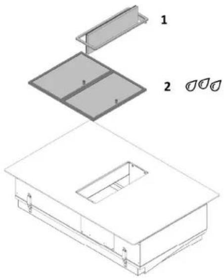
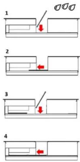
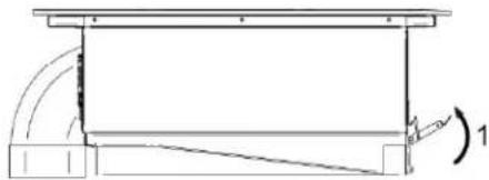
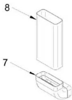
Remove the air inlet flap, by rotating the turnable part of 90 degrees. Then remove the air inlet flap by hand. Air inlet flap [1] and grease filters [2] can be easily inserted/removed by hands. See pictures below.
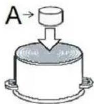
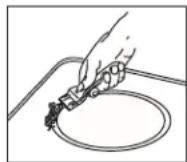
6.4 Remove liquids from the appliance
The water collector catches any liquids that flow into the appliance through the inlet opening. Do the following:
- Switch off the fan and deactivate the after-run function (see Operation chapter).
- Remove the air inlet nozzle and the grease filters.
EN CLEANING AND CARE
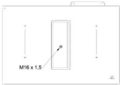
- Unscrew the cap on the bottom of the water collector with the help of a screwdriver.
- Place a bucket beneath the water collector to catch the pouring liquid.
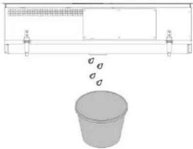
natural_image
Diagram showing a container with a lid and two side supports, with a separate 3D bucket below (no text or symbols)For a more thoroughful cleaning
- Switch off the fan and deactivate the after-run function (see Operation chapter).
- Remove the water collector which is positioned in the bottom part of the appliance using both hands and being cautious to not let it fall. There are two lever latches which have to be opened. See picture below.
Be careful! Hold the water collector with one hand before opening the lever latches!
natural_image
Pure technical line drawing of a mechanical assembly without any text, numbers, or symbols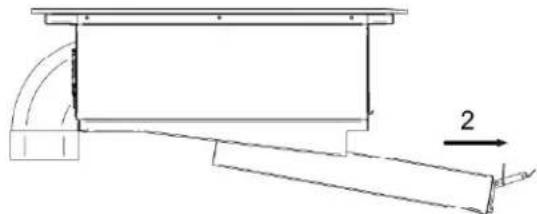
natural_image
Technical line drawing of a mechanical assembly with no visible text or symbols- Remove the water and clean the water collector by using a soft brush and a cleaner and degreaser in one.
- Rinse the water collector with hot water
• Dry the water collector with a tea towel - Fit the water collector to the appliance and close the lever latches.
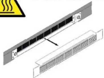
6.5 Regenerating and replacing the activated carbon filters (only in recirculation version)
After a prolonged use the activated carbon filters saturate and it is necessary to regenerate them with a heating process.
Do the following:
- Make sure that the cooktop and cooktop extractor are switched off (see the Operation chapter).
- Wait until the fan indicator shows 0.
- Remove the grid.
- Unscrew the filters box put it in an oven pre-heated to 180^ for one hour.
- Press below the symbol and hold for 3 seconds to reset the filter timer.
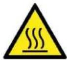
Be careful when handling the filters after the regeneration process: risk of burns!
natural_image
Technical diagram showing a panel with heat dissipation warning symbol (no text or labels)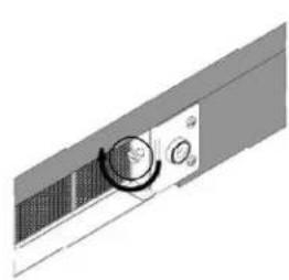
natural_image
3D rendering of a mechanical component with a circular knob and side panel (no text or symbols visible)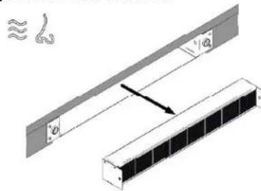
natural_image
Diagram showing two mechanical components with a spring-like inset and a directional arrow (no text or symbols)7 Troubleshooting
Interference with and repairs to the appliance by unqualified persons are dangerous as they can result in an electric shock or a short circuit. Do not interfere with or try to repair the appliance; this could cause injury to persons and damage to the appliance. Always have such work done by an expert, e.g. a Customer Service technician.
Please note
If your appliance is faulty, please check whether you can rectify the problem yourself by consulting these instructions for use.
You may be able to rectify some problems yourself. They are described below.
The fuses blow regularly?
Contact a technical customer service or an electrician!
Does the hob have tears or cracks?
There is a risk of electric shocks if the glass ceramic hob develops fractures, cracks, tears or damage of any other kind. Immediately switch off the appliance. Disconnect the fuse immediately and call Customer Service.
You can't switch your induction hob on?
- Has the wiring system (fuse box) in the house blown a fuse?
- Has the hob been connected to the mains?
- Is the childproof lock activated, i.e. does the display show an "L"?
- Are the sensor keys partly covered by a damp cloth, fluid or a metallic object? Please rectify.
- Are you using unsuitable cookware? See the section on Cookware for induction hobs.
- Verify if the water collector is absent or wrongly fixed.
The hob or a cooking zone has suddenly switched off
• Did you accidentally press the ON/OFF key?
- Are the sensor keys partly covered by a damp cloth, fluid or a metallic object? A buzzer will sound briefly. After a few seconds the appliance will switch off. Please remove the item located in front of the sensor keys.
- Has the safety cut-off device been activated, i.e. was a power level operated unchanged beyond a specific period of time? See the section on operation time limit.
The pot sign appears?
- A cooking zone has been switched on and the hob is expecting a suitable pot or pan to be placed on the cooking zone (pan recognition). Only when a pot has been placed on the cooking zone will power be supplied.
The pot sign still appears, even though a pot or pan was placed on the hob?
- The cookware is unsuitable for induction cooking or the pot or pan is too small.
LED display for cooking settings and residual heat display H does not come on or only partially.
- Display defective. Call Customer Service. Risk of burning, as the temperature warning is not guaranteed.
The symbol will blink and a time-limited continuous signal will sound.
- Food which has boiled over, cookware or other items are causing the touch control sensor keys to be consistently operated. Remedy: clean the surface or remove the item. To delete the symbol press the same key or switch the hob off and on.
Error code E2 is indicated?
The electronic unit is too hot. Check the installation of the hob. Make sure that there is sufficient ventilation. See the section on "Protection against overheating".
Do not heat-up empty pots and use appropriate cookware.
Error code E8 is indicated?
- Fault on the left or right hob fan. The suction opening is blocked or covered or the fan is defect.
- Check the installation of the hob. Make sure that there is sufficient ventilation.
No indication, no function?
The hob has been incorrectly connected. Connect the appliance to the appropriate power supply.
EN TROUBLESHOOTING
An error code (ERxx or Ex) is indicated?
- The appliance has developed a technical defect. Please call Customer Service.
Does the hob make noises (clicking or cracking noises) or can a buzzing sound be heard when the hob is switched on?
- This is design-specific and has no influence on quality and operation.
Does the cooling fan still operate after it has been switched off?
- This is normal since the electronic unit is being cooled down.
Is the cookware you are using making noises?
This is due to technical reasons; the induction hob and the pot are not at risk. Consider the hints in case some disturbing noises appear:
- Put the cookware centrically on to the respective cooking zone.
- Try to shift the cookware a little bit onto the cooking zone.
- When using 2 cooking zones in bridge mode, put the cookware centrically on both cooking
- Zones (i.e. the coverage of both cooking zones should be equal).
- Ensure that there are no foreign bodies between the glass ceramic and the cookware's bottom (e. g. salt grains).
- Ensure that a lid on top of the cookware is not able to vibrate.
- Try other cookware. Especially pots made of a compound material may cause noises.
- Avoid that 2 or more pots are touching each other.
Use cookware with flat bottom to avoid movement of the cookware.
8 Decommissioning and disposal
- Observe all safety and warning information (see the Safety section).
- Follow the enclosed manufacturer's information.
8.1 Decommissioning
Decommissioning is understood as final shutdown and disassembly. Following decommissioning, the device can either be installed into other units, sold on privately or disposed of.
Electricity connections may only be disconnected by qualified specialists.
- To decommission, switch the device off (see Operation section).
- Disconnect the device from the power supply.
8.2 Disassembly
For removal, the device must be accessible for disassembly and disconnected from the power supply.
- Undo the appliance fixture.
- Remove the silicone joints.
- Remove the device from the worktop by lifting it upwards.
- Remove any other accessories.
- Dispose of the old device and any contaminated accessories.
8.3 Disposing of the packaging
Please ensure the environmentally-friendly disposal of the packaging that came with your appliance. Recycling the packaging material saves on resources and cuts down on waste.
8.4 Disposing of old appliance
This symbol on the product or on its packaging indicates that this product may not be treated as household waste. Instead it must be handed over to the applicable collection point for the recycling of electrical and electronic equipment. By ensuring that this product is disposed of correctly you will help to protect the environment and human health, which could otherwise be harmed through the
inappropriate disposal of this product. For more detailed information about recycling this product, please contact your local city office, your household waste disposal service or the shop where you purchased the product.
2 Generel
2.1 Til din information p. 49
2.2 Tilsigtet brug p. 49
FARE
Aspirationssystem
natural_image
Four identical line drawings of cooking pots with crossed handles, no text or symbols presentnatural_image
Technical line drawing of a structural frame with curved supports and a horizontal beam (no text or symbols)
natural_image
Technical line drawing of a mechanical assembly with no visible text or symbolsnatural_image
Technical diagram showing a rack-mounted panel with a ventilation grille and an arrow pointing to it (no text or symbols present)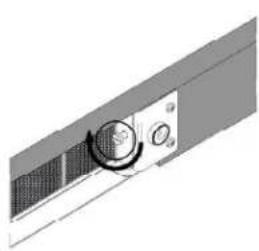
natural_image
Pure mechanical component diagram without any text, numbers, or symbols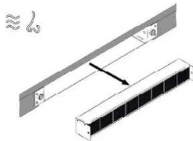
natural_image
Technical diagram showing a structural assembly with two components and a directional arrow (no text or symbols)7 Fejlfinding


- Installation A
- Installation A1
- Installation A2
- Installation A3
- Installation B1
- Installation B2
- Installation B3
- Installation B4
- Safety instructions and warnings
- Appliance description
- Operation
- Cleaning and care
- Troubleshooting
- Decommissioning and disposal
- General
- For your information...
- Intended use
- Explanation for symbols and indications
- DANGER
- CAUTION
- IMPORTANT
- NOTE
- WARNING OF ELECTRICAL ENERGY! RISK OF FATAL INJURY!
- CAUTION! HOT SURFACES!
- OBSERVE REGULATIONS FOR HANDLING ELECTROSTATICALLY SENSITIVE COMPONENTS AND MODULES (ESDS)
- For connection and operation
- General information about the hob
- For persons
- System description
- Operating panel
- How the cooktop extractor works
- Exhaust air mode
- Recirculation mode
- How the induction cooktop works
- Slide control
- What must be observed when operating sensor fields?
- Press the sensor field lightly or move your finger around
- The induction hob
- Advantages of the induction hob
- Technical informations
- OPERATION EN
- Appropriate cookware
- Note:
- Magnet test
- Dish recognition
- Hotplate may be damaged if:
- EN OPERATION
- Power regulation
- Energy saving tips
- Hob Control
- Slide Control
- Turn the hob on
- Turn cooking zones on
- Turn cooking zones off
- Turn the hob off
- Key-lock
- Activation
- Deactivation
- Child-Lock
- Pause
- While the Pause function is active
- Recall
- Remaining heat indicator
- Fast cooking
- Premature deactivation
- Power management system
- Heat-up time automatic
- Bridge
- EN
- OPERATION
- Warming
- Safety switch-off
- Example:
- Protection from overheating
- Timer
- Changing pre-set cooking time
- Checking remaining cooking time
- If you want to deactivate the timer prior the end of pre-set time:
- Alarm
- Timer setting
- Switching the alarm off
- Switching on the manual mode
- Notes
- Switching back to automatic mode
- Fan after-run
- Fan timer
- - Manual mode - situation 1
- - Manual mode – situation 2
- - Automatic mode
- Fan pause and recall
- Grease filter state indication
- Reset
- Carbon filter state indication (recirculation mode only)
- Power limitation setting
- The power limitation setting must ONLY be performed by a specialized technician.
- WARNING! The power level selected must be according to the fuses installed.
- Glass ceramic hob
- Cleaning after use
- Weekly cleaning
- Specific soiling
- Air inlet flap and grease filters
- Remove liquids from the appliance
- EN CLEANING AND CARE
- For a more thoroughful cleaning
- Be careful! Hold the water collector with one hand before opening the lever latches!
- Regenerating and replacing the activated carbon filters (only in recirculation version)
- Please note
- The fuses blow regularly?
- Does the hob have tears or cracks?
- You can't switch your induction hob on?
- The hob or a cooking zone has suddenly switched off
- The pot sign U appears?
- The pot sign U still appears, even though a pot or pan was placed on the hob?
- LED display for cooking settings and residual heat display H does not come on or only partially.
- The symbol will blink and a time-limited continuous signal will sound.
- Error code E2 is indicated?
- Error code E8 is indicated?
- No indication, no function?
- EN TROUBLESHOOTING
- An error code (ERxx or Ex) is indicated?
- Is the cookware you are using making noises?
- Decommissioning
- Electricity connections may only be disconnected by qualified specialists.
- Disassembly
- Disposing of the packaging
- Disposing of old appliance
- Generel
- FARE
- Fejlfinding
Brand : EICO
Model : Phantom Shift 80 N F
Category : Range hood