
SLC TWIN RT2 - Inverter Salicru - Free user manual and instructions
Find the device manual for free SLC TWIN RT2 Salicru in PDF.


| Product Type | Uninterruptible Power Supply (UPS) |
| Brand | Salicru |
| Model | SLC TWIN RT2 |
| Technology | Online Double Conversion |
| Power Rating | 2000 VA / 1800 W |
| Input Voltage | 230 VAC |
| Output Voltage | 230 VAC (Pure Sine Wave) |
| Input Frequency | 50/60 Hz (Auto Sensing) |
| Output Frequency | 50/60 Hz (Synchronized with Mains) |
| Battery Type | Sealed Lead-Acid, Maintenance-Free |
| Typical Backup Time (Full Load) | Approx. 10 minutes |
| Recharge Time | 4 to 6 hours (90% capacity) |
| Dimensions (W x D x H) | 482 x 445 x 88 mm (19" Rack-Mount) |
| Net Weight | 25 kg |
| Communication Ports | USB, RS-232, Dry Contacts |
| Display | LCD with Status Indicators |
| Protection Features | Overload, Short Circuit, Surge Protection, AVR |
| Cold Start Capability | Yes |
| Maintenance | Clean with dry cloth; periodic battery check |
| Repairability | User-replaceable batteries; spare parts available |
Frequently Asked Questions - SLC TWIN RT2 Salicru
User questions about SLC TWIN RT2 Salicru
0 question about this device. Answer the ones you know or ask your own.
Ask a new question about this device
Download the instructions for your Inverter in PDF format for free! Find your manual SLC TWIN RT2 - Salicru and take your electronic device back in hand. On this page are published all the documents necessary for the use of your device. SLC TWIN RT2 by Salicru.
USER MANUAL SLC TWIN RT2 Salicru
natural_image
Front view of a black server rack with 'SALICU' branding and digital display (no readable text beyond branding)UNINTERRUPTIBLE POWER SUPPLY SYSTEMS (UPS)
SLC TWIN RT2
0,7.. 10 kVA
General index
1. INTRODUCTION.
1.1. THANK YOU LETTER.
2. SAFETY INFORMATION.
2.1. USING THIS MANUAL.
2.1.1. Conventions and symbols used.
3. QUALITY ASSURANCE AND STANDARDS.
3.1. STATEMENT BY THE MANAGEMENT.
3.2. STANDARDS.
3.2.1. First and second environment.
3.2.1.1. First environment.
3.2.1.2. Second environment.
3.3. ENVIRONMENT.
4. PRESENTATION.
4.1. VIEWS.
4.1.1. Views of the device.
4.2. DEFINITION OF THE PRODUCT.
4.2.1. Nomenclature.
4.3. OPERATING PRINCIPLE.
4.4. UPS OPERATING MODES.
4.4.1. Notable features.
4.5. OPTIONAL EXTRAS.
4.5.1. Isolation transformer:
4.5.2. Exterior manual maintenance bypass.
4.5.3. Communication card.
4.5.3.1. Integration into computer networks using an SNMP adapter.
4.5.3.2. Modbus RS485.
4.5.3.3. Interface to relays.
4.5.4. Extendable guide kits for mounting in a rack cabinet.
5. INSTALLATION.
5.1. RECEPTION OF THE DEVICE.
5.1.1. Reception, unpacking and contents.
5.1.2. Storage.
5.1.3. Unpacking.
5.1.4. Transport to the site.
5.1.5. Siting, immobilising and considerations.
5.1.5.1. Rotation of the control panel with LCD display.
5.1.5.2. Vertical tower-type mounting.
5.1.5.3. Vertical tower-type mounting with backup extension (battery module).
5.1.5.4. Mounting as a rack in a 19" cabinet.
5.1.5.5. Rack mounting in a 19" cabinet with backup extension (battery module).
5.1.5.6. Vertical tower-type mounting with PDU.
5.1.5.7. Rack mounting in 19" cabinet with PDU.
5.1.5.8. Preliminary considerations before connection.
5.1.5.9. Preliminary considerations before connection, regarding the batteries and their protections.
5.1.5.10. Connection elements.
5.2. CONNECTIONS.
5.2.1. Connection of the input.
5.2.2. Connection to IEC connectors or output terminals.
5.2.2.1. Connection of loads in models up to 3 kVA.
5.2.2.2. Connection of loads in 4 to 10 kVA 10 kVA.
5.2.3. Connection to external batteries (backup extension).
5.2.4. Connection of the input earth terminal (⊥) and the earth connection terminal (⊥).
5.2.5. Terminals for EPO (emergency power off).
5.2.6. Terminals for digital input and output to relay. Only in models with power ratings > 3 kVA.
5.2.7. Manual bypass auxiliary contact terminals. Only in models with power ratings > 3 kVA.
5.2.8. Connection in parallel, only in models with power ratings > 3 kVA
5.2.8.1. Introduction in redundancy.
5.2.8.2. Installation and operation in parallel.
5.2.9. Communication port.
5.2.9.1. RS232 and USB port.
5.2.10. Smart slot for the integration of an electronic communication unit.
5.2.11. Protection against voltage spikes for the modem / ADSL / fax, etc., line..
5.2.12. Software.
5.2.13. Considerations before start-up with connected loads.
6. OPERATION.
6.1. STAR T-UP.
6.1.1. Checks before start-up.
6.2. UPS START-UP AND SHUTDOWN.
6.2.1. UPS start-up with mains voltage.
6.2.2. UPS start-up without mains voltage.
6.2.3. UPS shutdown with mains voltage.
6.2.4. UPS shutdown without mains voltage.
6.3. OPERATING PROCEDURE FOR A PARALLEL SYSTEM (ONLY IN 4 TO 10 KVA MODELS).
6.4. HOW TO ADD A UPS TO A SYSTEM IN PARALLEL OPERATION OR TO A FUNCTIONING SINGLE UPS (ONLY IN 4 TO 10 KVA MODELS).
6.5. HOW TO REPLACE A FAULTY UPS IN AN OPERATIONAL PARALLEL SYSTEM.
7. CONTROL PANEL WITH LCD DISPLAY.
7.1. GENERAL INFORMATION FOR THE SERIES.
7.1.1. Information represented by the display.
7.1.2. Common messages shown on the LCD display.
7.1.3. Common abbreviations shown on the display.
7.2. CONTROL PANEL FOR MODELS UP TO 3 KVA.
7.2.1. Composition of the control panel with LCD display.
7.2.2. Audible alarms.
7.2.3. Location of the adjustment parameters on the display.
7.2.4. Settings.
7.2.4.1. Ah configuration of parameter '12'.
7.2.4.2. Operating mode / Description of state.
7.2.4.3. Warning or alert codes.
7.2.4.4. Error or fault codes.
7.2.4.5. Warning or alert indicators.
7.3. CONTROL PANEL FOR 4 KVA TO 10 KVA MODELS.
7.3.1. Audible alarms.
7.3.2. Optical indications.
7.3.3. Location of the adjustment parameters on the display.
7.3.4. Settings.
7.3.4.1. Operating mode / Description of state.
7.3.4.2. Operating mode / Description of state.
7.3.4.3. Warning or alert codes.
7.3.4.4. Error or fault codes.
7.3.4.5. Warning or alert indicators.
8. MAINTENANCE, WARRANTY AND SERVICE.
8.1. BATTERY MAINTENANCE.
8.1.1. Notes for the installation and replacement of the battery.
8.2. UPS TROUBLESHOOTING GUIDE.
8.2.1. Troubleshooting guide for devices up to 3 kVA.
8.2.2. Troubleshooting guide for 4 kVA to 10kVA devices.
8.3. WARRANTY CONDITIONS.
8.3.1. Terms of the warranty.
8.3.2. Exclusions.
8.4. TECHNICAL SERVICES NETWORK.
9. ANNEXES.
9.1. GENERAL TECHNICAL SPECIFICATIONS.
9.2. GLOSSARY.
1. INTRODUCTION.
1.1. THANK YOU LETTER.
We thank you in advance for the trust placed in us in the purchasing of this product. Read this instruction manual carefully in order to familiarize yourself with its content, since the more you know and understand the equipment the greater your satisfaction, level of safety and optimization of its functionalities will be.
We remain at your disposal for any additional information or queries that you may wish to make.
Yours sincerely.
SALICRU
- The equipment described herein is capable of causing significant physical damage in the event of improper handling. For this reason its installation, maintenance and/or repair must be carried out exclusively by our personnel or by qualified personnel.
- Although no effort has been spared to ensure that the information in this user manual is complete and accurate, we are not responsible for any errors or omissions that may exist. The images included in this document are for illustrative purposes and may not represent exactly the parts of the equipment shown, therefore they are not contractual. However, any divergence that may arise will be remedied or solved with the correct labelling on the unit.
- Following our policy of constant evolution, we reserve the right to modify the characteristics, operations or actions described in this document without prior notice.
- Reproduction, copying, assignment to third parties, modification or total or partial translation of this manual or document, in any form or by any means, without previous written authorization by our firm is prohibited, with the full and exclusive property rights over the same being reserved by our firm.
2. SAFETY INFORMATION.
2.1. USING THIS MANUAL.
The documentation of any standard equipment is available to the customer on our website for download (www.salicru.com).
- For devices "powered by socket", this is the website for obtaining the user manual and "Safety Instructions" EK266*08.
- For devices with "permanent connection" via terminals, a CD-ROM or pen drive containing all necessary information for connection and start-up, including "Safety Instructions" EK266*08, may be supplied with it.
Before carrying out any action on the device relating to its installation or start-up, change of location, configuration or handling of any kind, carefully read the safety instructions.
The purpose of the user manual is to provide information regarding safety and explanations of the procedures for installation and operation of the equipment. Read them carefully and follow the steps indicated in the order established.

Compliance with the "Safety Instructions" is mandatory and the user is legally responsible for compliance and enforcement.
The equipment is delivered properly labelled for the correct identification of each of the parts, which together with the instructions described in this user manual allows the operations of installation and commissioning to be performed in a simple and orderly manner without having any doubts whatsoever. Finally, once the equipment is installed and operating, it is recommended to save the documentation downloaded from the website, CD-ROM or Pen Drive in a safe and easy-to-access place, for any future queries or doubts that may arise.
The following terms are used interchangeably in the document to refer to:
- 'SLC TWIN RT2', 'TWIN RT2', 'TWIN', 'RT2', 'device', 'unit' and 'UPS' - Uninterruptible power supply.
Depending on the context of the phrase, it can refer either to the actual UPS itself or to the UPS and the batteries, regardless of whether it is all assembled in the same metal casing - box - or not.
- "Batteries or accumulators". - Group or set of elements that stores the flow of electrons by electrochemical means.
• 'T.S.S.' - Technical Service and Support. - 'Client, installer, operator or user' - These are used interchangeably and by extension to refer to the installer and/or operator who will carry out the corresponding actions, and the same person may be responsible for carrying out the respective actions when acting on behalf of, or in representation of, same.
2.1.1. Conventions and symbols used.
Some symbols may be used and appear on the equipment, batteries and/or in the context of the user manual.
For more information, see section 1.1.1 of document EK266*08 on "Safety instructions".
3. QUALITY ASSURANCE AND STANDARDS.
3.1. STATEMENT BY THE MANAGEMENT.
Our goal is customer satisfaction, therefore this Management has decided to establish a Quality and Environment Policy, through the implementation of a Quality and Environmental Management System that will enable us to comply with the requirements demanded in the ISO 9001 and ISO 14001 and also by our Customers and Stakeholders.
Likewise, the management of the company is committed to the development and improvement of the Quality and Environmental Management System, through:
- Communication to the entire company of the importance of satisfying both the client's requirements as well as legal and regulatory requirements.
- The dissemination of the Quality and Environment Policy and the setting of the Quality and Environment objectives.
• Conducting reviews by the Management.
• Providing the necessary resources.
3.2. STANDARDS.
The SLC TWIN RT2 is designed, manufactured and sold in accordance with Quality Management Standard EN ISO 9001.
The marking indicates conformity with EC Directives through the application of the following standards:
• 2014/35/EU. - Low voltage safety.
• 2014/30/EU. - Electromagnetic Compatibility - EMC-
- 2011/65/EU. - Restriction of the use of hazardous substances in electrical and electronic equipment (RoHS).
According to the specifications of the harmonized standards. Reference standards:
- EN-IEC 62040-1. Uninterruptible Power Supplies -UPS-. Part 1-1: General and safety requirements for UPS used in user access areas.
- EN-IEC 60950-1. Information technology equipment. Safety. Part 1: General requirements.
- EN-IEC 62040-2. Uninterruptible Power Supplies -UPS-. Part 2: EMC requirements.

The manufacturer accepts no liability in the event of modification of or intervention on the device by the user.

WARNING!:
SLC TWIN RT2 0.7.. 3 kVA. This is a category C2 UPS. In a residential environment, this product may cause radio interference, in which case the user must take additional measures.
SLC TWIN RT2 4.. 10 kVA. This is a category C3 UPS. This
is a product for commercial and industrial application in the second environment; Installation restrictions or additional measures may be necessary to avoid disturbances.
It is not appropriate to use this equipment in basic life support applications (BLS), where a failure of the former can render vital equipment out of service or significantly affect its safety or effectiveness. It is also
not recommended in medical applications, commercial transport, nuclear installations, or other applications or loads, where a failure of the product can lead to personal or material damages.

The EC declaration of conformity of the product is available to the customer upon express request to our headquarters.
3.2.1. First and second environment.
The environment examples that follow cover most UPS installations.
3.2.1.1. First environment.
Environment including residential, commercial and light industry installations, directly connected, without intermediate transformers, to a low voltage public power grid.
3.2.1.2. Second environment.
An environment that includes all commercial, light industrial and industrial establishments that are not directly connected to a low voltage power grid supplying buildings used for residential purposes.
3.3. ENVIRONMENT.
This product has been designed to respect the environment and manufactured according to ISO 14001.
Recycling of the equipment at the end of its useful life:
Our company undertakes to use the services of authorized and regulatory companies to treat the set of products recovered at the end of their useful life (contact your distributor).
Packaging:
For the recycling of the packaging there must be compliance with the legal requirements in force, according to the specific regulations of the country where the equipment is installed.
Batteries:
Batteries pose a serious danger to health and the environment. The disposal of them shall be carried out in accordance with the laws in force.
4. PRESENTATION.
4.1. VIEWS.
4.1.1. Views of the device.
In Fig. 1 to Fig. 4, illustrations of the device are shown according to box size in relation to the power rating of the model. However, because the product is constantly evolving, discrepancies or slight contradictions may arise. If in any doubt, the labelling on the equipment itself will always prevail.

The nameplate of the device shows all of the values relating to its main properties and characteristics. Act accordingly for its installation.

Fig. 1. Front view of 0.7 to 10 kVA models and their battery modules for extended backups.
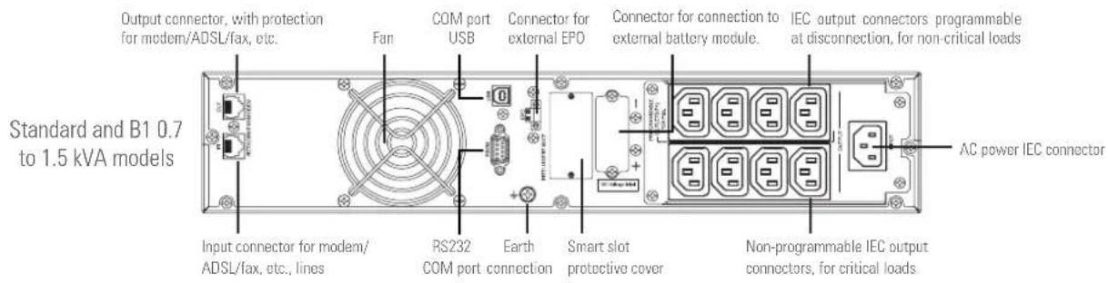

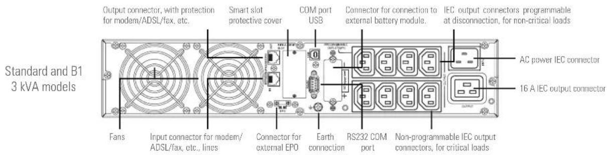


Fig. 2. Rear view of 4 to 10 kVA models.
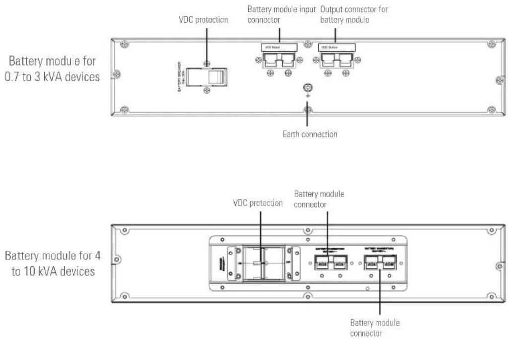
Fig. 3. Rear view of battery modules for extended backups.
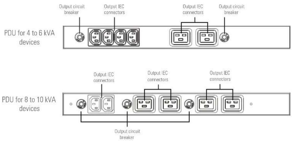
Fig. 4. Front view of PDU (power distribution unit).
4.2. DEFINITION OF THE PRODUCT.
4.2.1. Nomenclature.
SLC-8000-TWIN RT2 B1 WCO EE29503

flowchart
graph TD
    A["CF Frequency converter (device without batteries)."] --> B["SLC Brand acronym (for UPS)."]
    B --> C["8000 Power in VA."]
    C --> D["TWIN RT2 Device series."]
    D --> E["B1 Device with extra charger and without batteries."]
    E --> F["B0 Without batteries."]
    F --> G["W Private-label device."]
    G --> H["C0 'Made in Spain' marking on UPS and packaging (for customs purposes)."]
    H --> I["EE* Special customer specifications."]
MOD BAT TWIN RT2 2x6AB003 40A WCO EE29503
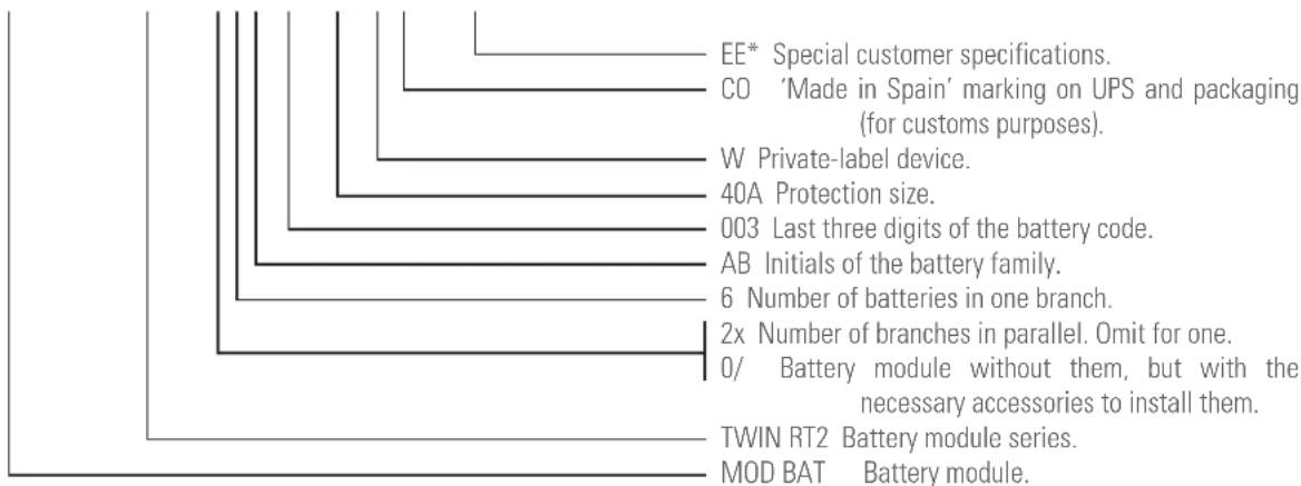

Note related to B0 and B1 batteries:
(B0) The device is supplied without batteries, but with a space reserved for installation in the same box for models whose standard version specifies this. For other models, the battery pack will be installed in the manner considered most appropriate (box, cabinet, rack, etc.).
For BO devices ordered, the cost of acquisition, installation and connection of the batteries shall always be borne by the customer or distributor and under their responsibility.
Accessories such as screws, cables and battery connection plates are considered optional and can be supplied upon request.
(B1) Device with a more powerful charger, which does not have a battery pack, nor the possibility of installing them in the same box.
If an accumulator module is required, it will need to be ordered as a separate item, which will be connected to the UPS using the supplied cable.
Before connecting a module or group of batteries to the device or another available module, it is necessary to check that the voltage value printed on the back of the device next to the battery connector is appropriate and that the polarity between the means of connection corresponds.
For more information, see Chapter 9 of this document.
4.3. OPERATING PRINCIPLE.
This manual describes the installation and operation of SLC TWIN RT2 series UPSs as devices that can be independently operated or connected in parallel (for models > 3 kVA). SLC TWIN RT2 series UPSs ensure optimum protection of any critical load, maintaining the supply voltage of the loads between the specified parameters without interruption during failure, deterioration or fluctuation of mains power, and come in a wide range of models (from 0.7 kVA to 10 kVA), enabling the end user to select the model that best suits his needs.
Thanks to their PWM (pulse width modulation) and double-conversion technology, SLC TWIN RT2 series UPSs are compact, cool, silent and high performance.
The double converter principle eliminates all mains power disturbances. A rectifier converts the AC current of the mains into DC current, thereby maintaining optimum battery charge level and powering the inverter, which, in turn, generates a suitable AC sine-wave voltage for continuously powering the loads. In the event of failure of the UPS's mains power, the batteries supply clean power to the inverter.
The design and construction of the SLC TWIN RT2 series UPS has been carried out in accordance with international standards. In addition, models with power ratings greater than 3 kVA can be expanded with the connection of additional modules with the same power in parallel to obtain N+X redundancy or an increase in the system's power.
Thus, this series has been designed to maximise the availability of critical loads and to ensure that your business is protected from variations in power distribution line voltage, frequency, electrical noise, cuts and micro-cuts. This is the primary goal of SLC TWIN RT2 series UPSs.
This manual applies to the standardised models shown in Tab. 1.
4.4. UPS OPERATING MODES.
- Normal mode
Device running supplying output voltage from the inverter. Mains power present with correct input voltage and frequency. - Battery mode.
Device running with mains voltage or frequency out of range or without AC input power, either due to mains failure or absence of cable connection, supplying output voltage from the batteries.
- Bypass mode.
Device running or not, supplying output voltage directly from the AC mains.
☐ With the inverter running, this operating mode may be due to an overload, blockage or inverter fault.
The actions for each incident will be as follows: Reduce the load connected to the output, unblock the device by resetting it – stop it and start it up again – and, if the blockage or fault remains, contact T.S.S.
With the inverter shut down, the output supplies mains power directly through the static bypass of the device provided that it has AC input power.
• Frequency converter (CF) mode.
Operating mode of the UPS as a frequency converter. In this mode, the static bypass is disabled by the condition of disparate input and output frequencies.

Even if the LCD display on the backlit control panel shows messages, it does not mean that the inverter is operational. It is switched on by pressing the 'ON' button on the control panel, see Chapter 6.
4.4.1. Notable features.
- True on-line with double-conversion technology and output frequency separate from the mains.
- Output power factor 1, except for B1 models where it is 0.8. Pure sine waveform, suitable for almost all kinds of loads.
- Input power factor > 0.99 and high overall performance (between 0.89 and 0.91 for 0.7 to 3 kVA models and > 0.93 for higher power ratings). Greater energy savings and lower user installation costs (wiring), as well as low distortion of the input current, which reduces pollution in the power supply network.
- Great adaptability to the worst conditions of the mains. Wide input voltage, frequency and waveform ranges, thus avoiding excessive dependence on limited battery power.
- Possibility of fast and easy backup extension by adding modules in rack format. Each battery module has two connectors for easy connection to the device and other identical modules.
- Availability of battery chargers of up to 6 A to reduce battery recharge times.
- N+X redundant parallel connection to increase reliability and flexibility in power models > 3 kVA, with a maximum of 3 devices in parallel.
- Selectable high-performance mode (ECO MODE) > 0.95 to 0.99 depending on model. Energy savings, economically beneficial for the user.
- Possibility of starting the device without mains power supply or discharged battery. Be careful with this aspect because the greater the batteries are discharged, the more the backup will be reduced.
- Intelligent battery management technology is very useful for extending the life of accumulators and optimising recharge times.
- Standard communication options via the RS232 serial port or USB port.
- Digital input for device Start/Stop and 'Error or fault' digital output in models with power ratings > 3 kVA.
• Remote emergency power off control (EPO). - Control panel with LCD display available on all models and LED indicators on devices with power ratings > 3 kVA.
- Availability of optional connectability cards to improve communication capabilities.
- Device that can be installed as a tower or rack using the accessories supplied. The control panel can be rotated to adapt to either format.
| Model Type Input/output type | ||
| SLC-700-TWIN RT2 | Standard | Single-phase / Single-phase. |
| SLC-1000-TWIN RT2 | ||
| SLC-1500-TWIN RT2 | ||
| SLC-2000-TWIN RT2 | ||
| SLC-3000-TWIN RT2 | ||
| SLC-4000-TWIN RT2 | ||
| SLC-5000-TWIN RT2 | ||
| SLC-6000-TWIN RT2 | ||
| SLC-8000-TWIN RT2 | ||
| SLC-10000-TWIN RT2 | ||
| SLC-700-TWIN RT2 (B0) | Without batteries | |
| SLC-1000-TWIN RT2 (B0) | ||
| SLC-1500-TWIN RT2 (B0) | ||
| SLC-2000-TWIN RT2 (B0) | ||
| SLC-3000-TWIN RT2 (B0) | ||
| SLC-4000-TWIN RT2 (B0) | ||
| SLC-5000-TWIN RT2 (B0) | ||
| SLC-6000-TWIN RT2 (B0) | ||
| SLC-8000-TWIN RT2 (B0) | ||
| SLC-10000-TWIN RT2 (B0) | ||
| SLC-700-TWIN RT2 (B1) | Long backup with additional charger | |
| SLC-1000-TWIN RT2 (B1) | ||
| SLC-1500-TWIN RT2 (B1) | ||
| SLC-2000-TWIN RT2 (B1) | ||
| SLC-3000-TWIN RT2 (B1) | ||
| SLC-4000-TWIN RT2 (B1) | ||
| SLC-6000-TWIN RT2 (B1) | ||
| SLC-8000-TWIN RT2 (B1) | ||
| SLC-10000-TWIN RT2 (B1) | ||
Tab. 1. Standardised models.
4.5. OPTIONAL EXTRAS.
Depending on the configuration chosen, the device may include any of the following options:
4.5.1. Isolation transformer:
The isolation transformer provides galvanic isolation in order to completely isolate the output from the input and/or change neutral mode.
The placement of an electrostatic screen between the primary and secondary windings of the transformer provides a high level of electrical noise attenuation.
The isolation transformer can be physically placed at the input or output of the UPS depending on the technical conditions of the whole system (device supply voltage and/or load voltage, characteristics or their type, etc.).
In parallel systems, it is not possible to operate with independent transformers for each UPS; on the contrary, it is necessary to have a single common element for the total adequate power. In any event, it will always be supplied as a peripheral component external to the device itself in a separate box.
4.5.2. Exterior manual maintenance bypass.
The purpose of this option is to electrically isolate the device from the mains and the critical loads without cutting the power to the latter. In this way, maintenance or repair operations on the device can be carried out without interruptions to the power supply of the protected system, while preventing unnecessary hazards for the technical personnel.
4.5.3. Communication card.
The UPS features a slot at the rear for inserting one of the following communication cards.
4.5.3.1. Integration into computer networks using an SNMP adapter.
Large computer systems based on LANs and WANs that integrate servers in different operating systems must provide the system manager with ease of control and administration. This facility is obtained through an SNMP adapter, which is universally supported by the main software and hardware manufacturers.
Connection of the UPS to the SNMP is internal while that of the SNMP to the computer network is made through a RJ45 10 base connector.
4.5.3.2. Modbus RS485.
Large computer systems based on LANs and WANs often require that communication with any element that is integrated into the computer network be made through a standard industrial protocol.
One of the most used standard industrial protocols on the market is the MODBUS protocol.
4.5.3.3. Interface to relays.
- The UPS has, as an option, an interface to relays card that provides digital signals in the form of potential-free contacts, with a maximum applicable voltage and current of 240 V AC or 30 V DC and 1A.
- This communication port enables dialogue between the device and other machines or devices through the relays supplied in the terminal block arranged on the same card, with a single common terminal for all of them.
From the factory, all contacts are normally open and can be changed one by one, as indicated in the information supplied with the optional extra.
- The most common use of these types of ports is to provide the necessary information to the file-closing software.
- For more information, contact our T.S.S. or our nearest distributor.
4.5.4. Extendable guide kits for mounting in a rack cabinet.
An extendable and unique guide kit is available for all device models, valid for any kind of rack-type cabinet.
These guides allow the installation of any TWIN RT2 device unit and possible battery modules in the case of extended backups, as if it were a rack in its respective cabinet.
5. INSTALLATION.
- Read and respect the Safety Information, described in chapter 2 of this document. Failure to obey some of the instructions described in this manual can result in a serious or very serious accident to persons in direct contact or in the vicinity, as well as faults in the equipment and/or loads connected to it.
- In addition to the device's own user manual, other documents are supplied on the CD-ROM or documentation pen drive. Consult them and strictly follow the indicated procedure.
- Unless otherwise indicated, all actions, instructions, guidelines and notes are applicable to the devices, whether or not they form part of a parallel system.
5.1. RECEPTION OF THE DEVICE.
- Pay attention to section 1.2.1. of the safety instructions -EK266 * 08- in all matters relating to the handling, movement and location of the unit.
- Use the most suitable means to move the UPS while it is packed, with a transpalet or forklift.
- Any handling of the device must be carried out in accordance with the weights shown in the technical specifications according to the model, indicated in chapter '9. Annexes'.
5.1.1. Reception, unpacking and contents.
• Reception. Check that:
☐ The data on the label affixed to the packaging correspond to those specified in the order. Once the UPS is unpacked, check the previous data with those of the equipment nameplate.
If there are discrepancies, file the disagreement as soon as possible, citing the equipment manufacture number and the delivery note references.
☐ It has not suffered any mishaps during transportation (packaging and impact indicator in perfect condition). Otherwise, follow the protocol indicated on the label attached to the impact indicator, located on the packaging.
- Unpacking.
☐ To check the contents, it will be necessary to remove the packaging.

Complete the unpacking according to the procedure of section 5.1.3. Content.
- Content
☐ 0.7 to 3 kVA device:
-1 UPS.
-Quick guide on paper.
-Information for warranty registration.
-1 USB cable.
-3 cables with IEC connectors for loads.
-1 cable for the device's AC power supply.
-2 metal pieces for use as handles and screws for installing the unit in a rack cabinet.
-4 plastic pieces for use as a base to facilitate the arrangement of the UPS as a tower (vertical position).
☐ Optional battery module for 0.7 to 3 kVA UPS:
-1 battery module.
-Information for warranty registration.
-2 metal pieces for use as handles and screws for installing the unit in a rack cabinet.
-2 plastic pieces to extend the base of the UPS and enable the arrangement of the attached battery module in its mounting as a tower.
-1 cable for interconnecting the battery module and UPS or other module.
☐ 4 to 10 kVA device:
-1 UPS.
-1 PDU module (power distribution unit).
-Information for warranty registration.
-2 metal pieces for use as handles and screws for installing the UPS in a rack cabinet.
-2 metal pieces for use as handles and screws for installing the PDU in a rack cabinet.
-1 metal piece and screws for mounting the PDU attached to the UPS arranged as a tower.
-1 USB cable.
-4 plastic pieces for use as a base to facilitate the arrangement of the UPS as a tower (vertical position).
-1 cable for connecting the communication bus. Useful only for connection to a parallel device.
-1 cable for connecting the current bus. Useful only for connection to a parallel device.
-1 cable for interconnecting the battery module and UPS.
☐ 4 to 10 kVA battery module:
-1 battery module.
-Information for warranty registration.
-2 metal pieces for use as handles and screws for installing the unit in a rack cabinet.
-2 plastic pieces to extend the base of the UPS and enable the arrangement of the attached battery module in its mounting as a tower.
-1 cable for interconnecting the battery module and another module.
- Once the reception is completed, it is advisable to re-pack the UPS until it is put into service in order to protect it against mechanical shock, dust, dirt, etc.
- The packaging of the device consists of a wooden pallet, cardboard or wooden box, depending on the item, expanded polystyrene corners, polyethylene cover and strapping, all of which are recyclable materials. When the packaging requires disposal, it must be carried out in accordance with current laws.
We recommend keeping it for at least 1 year.
5.1.2. Storage.
- The device should be stored in a dry, ventilated room and protected from rain, dust, and water or chemical splashes. It is advisable to keep each device and battery unit in its original packaging, as it has been specifically designed to ensure maximum protection during transportation and storage.
- For devices that contain Pb-Ca batteries, the charging times indicated in Tab. 2 of document EK266*08, determined by the temperature to which they
are exposed, must be respected, otherwise the warranty may be invalidated.
- After this period, connect the device to the mains together with the battery unit if applicable, start it according to the instructions described in this manual and charge for 12 hours.
In parallel systems, it is not necessary to interconnect devices before battery charging. Each of them can be treated independently to charge them.
- Then shut down the device, disconnect it and store the UPS and batteries in their original packaging, noting the new date for recharging the batteries on a document as a record or even on the packaging itself.
- Do not store the devices where the ambient temperature exceeds 50^ C or drops below -15^ C, as this may cause degradation of the electrical characteristics of the batteries.
5.1.3. Unpacking.
- The packaging of the device consists of a cardboard box, expanded polystyrene (EPS) or polyethylene foam (EPE) corners, polyethylene cover and strapping, all of which are recyclable materials; consequently, if it requires disposal, it must be carried out in accordance with current laws. We recommend keeping the packaging in case it needs to be used in the future.
• Proceed as follows:
☐ Cut the straps around the cardboard box.
☐ Remove the accessories (cables, brackets, etc.)
☐ Remove the device or battery module from the box with the help, if necessary, of a second person depending on the weight of the model or using appropriate mechanical means.
☐ Remove the protective corners from the device and the plastic bag.

Do not leave the plastic bag within the reach of children to avoid danger of suffocation.
☐ Inspect the device before proceeding and, in the event of finding damage, contact the supplier or, failing that, our firm.
5.1.4. Transport to the site.
It is recommended to transport the UPS by means of a pallet jack or the most appropriate method considering the distance between the two points.
If the distance is considerable, it is recommended to transport the device in its packaging to the installation site and then unpack it.
5.1.5. Siting, immobilising and considerations.
- All TWIN RT2 series UPSs are designed to be mounted as a tower model -vertical arrangement of the device- or rack -horizontal arrangement- for installation in 19" cabinets, regardless of whether they operate independently or as parallel systems, whether or not they have a battery module or whether the available backup is standard or extended (greater number of battery modules).
Follow the instructions indicated in the sections relating to
either of the two possibilities, according to the particular configuration of your device.
- Figs. 5 to 11 show, by way of example, illustrations of a device with or without battery module. These illustrations provide help and guidance in the steps to follow, but the instructions are not intended to refer to a single model, although, in practice, the actions to be carried out are always the same for all of them.
• For all instructions regarding connections, refer to section 5.2.
5.1.5.1. Rotation of the control panel with LCD display.
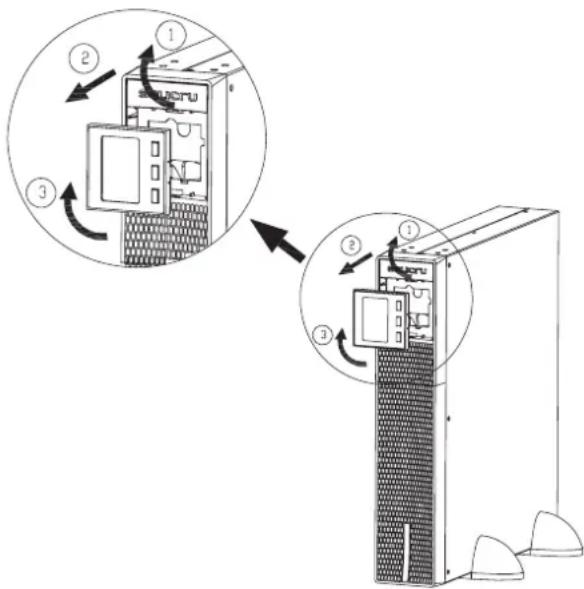
Fig. 5. Rotation of the control panel with LCD display on the plastic front trim.
- To facilitate the reading of messages on the display when the device is installed vertically, it is possible to rotate the control panel clockwise by 90° (see Fig. 5).
- Likewise, reverse the rotation of the control panel if a device arranged as a tower needs to be installed as a rack. In this case, the rotation of the control panel will be anticlockwise.
• Proceed as follows:
☐ Insert fingertips into the recesses of the plastic trim around the display and pull outwards.
☐ Rotate the control panel with LCD display 90^ to the right with respect to its initial position and insert it back into the front.
5.1.5.2. Vertical tower-type mounting.
- Rotate the control panel according to section 5.1.5.1.
- Take the 4 pieces of plastic supplied with the device and join them together in twos to obtain two bases.
- Place the UPS upright between the two bases at a distance of 70 mm from each end (see Fig. 6).

5.1.5.3. Vertical tower-type mounting with backup extension (battery module).
- The description in this section refers to a device with a single battery module. For a greater number, proceed in a similar way.
- Rotate the control panel according to section 5.1.5.1
• Take the 4 plastic pieces in the form of an angle supplied with the UPS and the two supplied with the battery module,
and install them to obtain two bases to hold the device and the battery module.
- Place the UPS and battery module upright between the two bases (see Fig. 7) and at a distance of 70 mm from each end, similar to as shown in Fig. 7.

natural_image
Line drawing of a server unit with two side panels showing internal components and a circular arrow indicating rotation (no text or symbols)Fig. 7. Vertically mounted tower-type model with backup extension (battery module).
5.1.5.4. Mounting as a rack in a 19" cabinet.
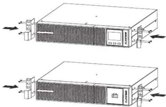
- To mount a device in a 19" rack cabinet, proceed as follows (see Fig. 8):
☐ Using the supplied screws, fix the two adapter angles for use as handles on each side of the UPS, respecting your hand.
☐ To install the device in a rack cabinet, it is necessary to have internal lateral guides for use as supports. Alternatively, and upon request, we can supply universal slides for use as guides, for installation by the user.
Mount the guides at the required height, ensuring correct tightening of the fixing screws and appropriate fitting in the machining, according to each case.
Place the device onto the guides and insert it all the way to the back.
Depending on the device model and weight, and/or whether it is installed in the upper or lower part of the cabinet, it is recommended that two people carry out the installation operations.
☐ Fix the UPS to the cabinet frame using the screws supplied with the handles. Fig. 6. Vertical tower-type mounting.

natural_image
Line drawing of a server rack with control panel and drive unit (no text or symbols)
natural_image
Technical line drawing of a server rack unit with mounting hardware (no text or symbols)Fig. 8. Rack-type mounting in a 19" cabinet.
5.1.5.5. Rack mounting in a 19" cabinet with backup extension (battery module).
- This section describes a device with one battery module. For more battery modules, repeat the same procedure for each of them.
- To install a device and its battery module in a 19" rack cabinet, proceed as follows (see Fig. 9):
☐ Using the supplied screws, fix the two adapter angles for use as handles on each side of the UPS, respecting your hand. Repeat the same procedure for the battery module.
☐ To install each unit, UPS and battery module in a rack cabinet, it is necessary to have internal lateral guides for use as supports. Alternatively, and upon request, we can supply universal slides for use as guides, for installation by the user.
Mount the guides at the required height, ensuring correct tightening of the fixing screws and appropriate fitting in the machining, according to each case.
Place the device onto the guides and insert it all the way to the back. Proceed in the same way for the battery module.
Depending on the weight of each unit according to the type of device and battery module, and/or whether it is installed in the upper or lower part of the cabinet, it is recommended that two people carry out the installation operations.
☐ Fix the UPS and the battery module to the cabinet frame by means of the screws supplied with the respective handles.
natural_image
Technical line drawing of two server units with ventilation ducts and control panel (no text or symbols)
natural_image
Technical line drawing of a server rack unit with cooling fans and ventilation ducts (no text or symbols)Fig. 9. Rack-mounted model in a 19" cabinet with backup extension (battery module).
5.1.5.6. Vertical tower-type mounting with PDU.
4 to 10 kVA models are supplied as standard with a PDU module, designed to be attached to the side of the device. Fix it to the UPS using the plate supplied as a support as shown in Fig. 10.

natural_image
Line drawing of a server rack unit with control panel and drive buttons (no text or symbols)Fig. 10. Vertically mounted tower-type model with PDU.
5.1.5.7. Rack mounting in 19" cabinet with PDU.
Similar to the UPS, the PDU module has angles for use as handles for mounting in a rack cabinet.
• Proceed as follows (see Fig. 11):
☐ Using the supplied screws, fix the two adapter angles for use as handles on each side of the PDU, respecting your hand.
According to each case, perform the steps indicated in section 5.1.5.4 or 5.1.5.5.
☐ To install the PDU in a rack cabinet, it is necessary to have internal lateral guides for use as supports, just like for the UPS and/or battery module. Follow the guidelines described in section 5.1.5.4 or 5.1.5.5 for everything related to the guides.
Place the PDU onto the guides and insert it all the way to the back.
☐ Fix it to the cabinet frame using the screws supplied with the handles.

natural_image
Line drawing of a server rack unit with multiple ports and ventilation grilles (no text or symbols)Fig. 11. Rack-type mounting in a 19" cabinet with PDU.
5.1.5.8. Preliminary considerations before connection.
- In the description of this manual, reference is made to the connection of terminals and switch operations that are only available in some versions or devices with extended backup. Ignore the related operations if your unit does not feature them.
- Thermal control of these devices is carried out with the passage of forced air from the front to the rear.
The front surface and about 15 cm on the rear side should be left free of obstructions to facilitate the free circulation of air for ventilation. - Follow and respect the instructions described in this section referring to the installation of a single device or a system in parallel.
• Protection or external manual bypass board:
☐ The system will have at least one short-circuit protection on the UPS's power supply line.
☐ It is advisable to have an external manual bypass board fitted with input, output and manual bypass protections in single systems.
For parallel systems, it is essential to have a distribution or manual bypass board. The board's circuit breakers must be able to isolate a UPS from the system in the event of a fault and power the loads with the others, either during periods of preventative maintenance or during breakdown and repair.
- Upon request, we can supply an external manual bypass board for a single device or parallel system.
You can also choose to manufacture it, taking into account the version and configuration of the device or system available and the documentation contained in the CD-ROM or pen drive relating to 'Recommended installation'.
- on the documentation supplied with this user manual and/or on the CD-ROM or pen drive, information is available on 'Recommended installation' for each input and output configuration. This documentation includes wiring diagrams and information about the sizes of the protections and the minimum cross sections of cables connected to the device according to their rated working voltage. All values are calculated for a maximum total cable length of 30 m between the distribution board, equipment and loads.
☐ For longer lengths correct the cross sections to avoid voltage drops, respecting the regulations or standards corresponding to the country.
☐ In the same documentation and for each configuration, information for 'N' units in parallel, as well as backfeed protection characteristics, is available.
- In parallel systems, the length and cross section of the cables that run from the distribution or manual bypass board to each UPS and from these to the board will be the same for all of them without exception.
- The cross section of the cables must always be considered in relation to the size of the terminals of the switches, so that they are correctly fastened across their entire cross section for optimum contact between the two elements.
- Only rated currents are printed on the nameplate of the equipment as indicated by the EN-IEC 62040-1 safety standard. For the calculation of the input current, the power factor and the equipment's own performance have been considered.
Overload conditions are considered a non-permanent and exceptional working mode, and will not be taken into account in the application of the protections. Do not connect appliances or devices which may overload the UPS to the terminals and/or outlets, such as motors.
- If peripheral input, output or bypass elements such as transformers or autotransformers are added to the UPS or parallel system, the currents indicated on the nameplates of these elements must be taken into consideration in order to use the appropriate cross sections, in compliance with local and/or national Low Voltage Electrotechnical Regulations.
- When a galvanic isolation transformer is added to a UPS or parallel system as an optional extra, as standard or independently, either on the input line, at the output or both, it must be fitted with protection against indirect contact (differential circuit breaker) at the output of each transformer, since, due to its own insulation properties, it will prevent the tripping of the protections placed on the primary of the isolation transformer in case of electric shock on the secondary (output of the isolation transformer).
- We remind you that all the isolation transformers installed or factory supplied, have the output neutral grounded through a bridge between the neutral terminal and ground. If the isolated output neutral is required, this bridge must be removed, taking the precautions indicated in the respective local and/or national low voltage regulations.
- This device is suitable for installation in networks with TT, TN-S, TN-C or IT power distribution systems, taking into account at the time of installation the particularities of the system used and the national electrical regulations of the destination country.
- The SLC TWIN RT2 features terminals for the installation of an external emergency power off button (EPO) or, failing that, a single device must be installed to cut the power supply to the loads in any operating mode.
5.1.5.9. Preliminary considerations before connection, regarding the batteries and their protections.
- SLC TWIN RT2 devices from 0.7 to 3 kVA incorporate the batteries in the same box as the device, except for B0, B1 and higher power models.
-
The battery protection of the device and of any accumulator module is always by means of internal fuses that are not accessible to the user.
-
IMPORTANT FOR SAFETY: If batteries are installed independently, the accumulator group must be fitted with a bipolar circuit breaker or disconnect fuse of the size indicated in Tab. 2.
- Inside the battery module, there are HAZARDOUS VOLTAGES with risk of electric shock, so it is classified as a RESTRICTED ACCESS AREA.
- Do not handle the fuse holder or battery circuit breaker when the device is running.
- In the mains power of the device or parallel system is cut for longer than a simple intervention and it is expected that it will be out of service for a prolonged period time, the system must be shut down completely.
- The battery circuit is not isolated from the input voltage. Dangerous voltages can occur between the terminals of the battery group and the earth. Check that there is no input voltage before intervening on the terminals.
5.1.5.10. Connection elements.
- All of the device's electrical connections are made from the back of each unit:
☐ Input and output connection.
-For models up to 3 kVA.
Input by means of a cable with plug, connectable to the UPS through an IEC connector.
Outputs through IEC connectors.
-For models with power ratings greater than 3 kVA. Terminals for powering the device and loads. It is necessary to remove the transparent protective cover to access the terminals.

Replace the cover after making the connections to prevent possible accidents direct contact, especially in tower mountings e is a greater risk.
☐ Connection to batteries.
- The device and battery module have a polarised connector.
Remove the screws and protective cover of the connector before interconnecting it.
-All battery modules have two connectors that enable backup extension.
☐ Communication connectors available:
-DB9 for RS232. In models up to 3 kVA, the interface to relays signals are supplied with the same connector.
-USB to operate the UPS as a PC peripheral.
-Digital input and output (only in models > 3 kVA).
-For connection to external EPO button.
-Auxiliary contact for the manual bypass switch (only in models > 3 kVA).
☐ DB15 communication bus connectors and analogue current signal block for connecting systems in parallel (only in models > 3 kVA).
To access the signal block, it is necessary to remove its protective cover.
☐ Slot for the integration of one of the optional electronic communication units. Remove the fixing screws and plastic cover to enable it to be inserted.
- It is recommended to use terminals on all of the ends of the cables connected to power terminals (input and output).
- Check that the terminal screws are correctly tightened.
5.2. CONNECTIONS.
5.2.1. Connection of the input.
• 0.7 to 3 kVA models:
☐ Take the power cable with plug and IEC connector on the end and insert the latter into the input connector of the UPS.
☐ Plug the power cable into an AC power socket.
• 4 to 10 kVA models:
As the device has Class I protection against electric shock, it is essential to install a protective earth conductor (connect earth (Connect this conductor before supplying voltage to the input terminals.
☐ Connect the power cables to the input terminals respecting the order of the phase (R) and the neutral (N) indicated on the labelling of the device and in this manual. Pay particular attention when connecting the power cables to the input terminals and do not reverse the connection to the output terminals or vice versa. Failure to respect the order will result in faults. Where there are discrepancies between the labelling and the instructions in this manual, labelling shall always prevail.
☐ In accordance with safety standard EN-IEC 62040-1, the facility must be equipped with an automatic backfeed protection system, such as a contactor, which prevents the appearance of hazardous voltage or power on the UPS input line during a mains failure (see Fig. 12). The standard applies to both individual units and all UPSs in parallel systems.
There can be no derivation of the line that goes from the backfeed protection to the UPS, as this would breach the safety standard.
☐ Warning labels shall be affixed to all primary power switches installed in areas remote from the equipment to alert electrical maintenance personnel of the presence of a UPS in the circuit.
The label shall bear the following text or an equivalent:
Before working on the circuit.
- Isolate the uninterruptible power supply system (UPS).
- Check the voltage between all terminals, including the protective earth.

Return voltage risk of the UPS.
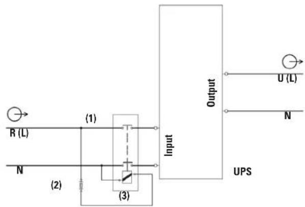
(1) Automatic backfeed protection system external to the UPS (EN-IEC 62040-1).
(2) Fuse holder and general purpose fuse 250V AC / 3A type F.
(3) 230V AC bipolar contactor with minimum contact spacing of 1.4 mm and coil with same voltage and the minimum current indicated on the nameplate of the UPS (input or bypass as appropriate).
For parallel systems, each device must have its own separate backfeed protection.
Fig. 12. Backfeed protection wiring diagrams.
5.2.2. Connection to IEC connectors or output terminals.
-
SLC TWIN RT2 devices feature female IEC output connectors or terminals depending on the power of the model:
Models up to 2 kVA: 2 groups of 4 x 10A IEC connectors identified as «OUTPUT» and «OUTPUT PROGRAMMABLE (P1)», configurable through the control panel and/or ViewPower.
☐ 3 kVA models: same connectors as models up to 2 kVA and an additional 16A IEC connector.
☐ 4 to 10 kVA models: 1 group of output terminals. In these models, a PDU (power distribution unit) is supplied to connect to the output terminals of the UPS. Through it, loads can be powered directly through the two or three groups of 10 or 16 A IEC connectors protected by a selective circuit breaker. -
Do not connect loads that in their entirety exceed the specifications of the device, as this would cause inconvenient cuts in the power supply of the loads connected to the output.
- If, in addition to the more sensitive 'critical loads', it is necessary to connect high-consumption inductive loads, such as for laser printers or CRT monitors, the starting up of these peripherals will need to be taken into account to prevent the device from crashing.
We do not recommend connecting loads of this type due to the amount of power they absorb from the UPS.
5.2.2.1. Connection of loads in models up to 3 kVA.
- Connect the loads to the 10 A IEC connectors.
It is important to consider the two groups of IEC connectors available, those for 'critical loads' and those for 'non-critical loads'.
By definition, 'critical loads' are considered to be those that can cause economic damage if they stop functioning or function incorrectly.
The IEC connectors indicated in Fig. 2 as 'non-critical loads' can be programmed as such through the control panel. In this case, the backup of the batteries for the loads connected to the IEC connectors indicated in Fig. 2 as 'critical loads' will be reserved. Take into account that they are set by default as 'critical loads'.
- The 3 kVA models also have a 16A IEC connector that enables the connection of a load of the total power of the device.
5.2.2.2. Connection of loads in 4 to 10 kVA 10 kVA.
- In the device has Class I protection against electric shock, it is essential to install a protective earth conductor (connect earth (Connect this conductor before supplying voltage to the input terminals.
- Connect the loads to output terminals U (L) and N, respecting the order of the phase and the neutral indicated on the labelling of the device and in this manual (see Fig. 2). Where there are discrepancies between the labelling and the instructions in this manual, labelling shall always prevail.
- Together with the device, a PDU with several 10 and 16A IEC output connectors with their respective circuit breaker is supplied.
When the utility of the PDU is required to power the loads, it will be necessary to connect its input cables to the output of the UPS, respecting the following assignment:
☐ Black or brown cable to phase U (L).
☐ Red or blue cable to neutral (N).
□ Green-yellow cable to earth terminal
- With regard to the protection that must be placed at the output of the UPS when the PDU is not used, we recommend distributing the output power over at least four lines. Each of them will have a circuit breaker with a value of one quarter of the rated power. This type of output power distribution will allow that in the event of a fault in any of the machines connected to the equipment, which provokes a short circuit, does not affect more than the line that is broken.
The remaining connected loads will have continuity assured due to the tripping of the protection, only in the line affected by the short circuit.
5.2.3. Connection to external batteries (backup extension).
- Failure to comply with the instructions in this section and Safety Instructions EK266*08 carries a high risk of electric shock and even death.
- SLC TWIN RT2 devices from 0.7 to 3 kVA incorporate the batteries in the same box as the device, except for B0, B1 and higher power models.
- The battery protection of the device and of any accumulator module is always by means of internal fuses that are not accessible to the user.
- IMPORTANT FOR SAFETY: If batteries are installed independently, the accumulator group must be fitted with a bipolar circuit breaker or disconnect fuse of the size indicated in Tab. 2.
| Model | Rated voltage of batteries | Minimum values, fast type fusesDC voltage (V) current (A) | |
| SLC-700-TWIN RT2 | (12 V x 3) = 36 V | 125 | 20 |
| SLC-1000-TWIN RT2 32 | |||
| SLC-1500-TWIN RT2 | |||
| SLC-2000-TWIN RT2 (1 V x 4) = 48 V | 50 | ||
| SLC-3000-TWIN RT2 (1 V x 6) = 72 V | |||
| SLC-4000-TWIN RT2 | (12 V x 16) = 192V 300 | 20 | |
| SLC-5000-TWIN RT2 | 32 | ||
| SLC-6000-TWIN RT2 | |||
| SLC-8000-TWIN RT2 40 | |||
| SLC-10000-TWIN RT2 50 | |||
Tab. 2. Protection features between device and battery module.
- Before starting the connection process between battery module or modules and device, check that the device and loads are 'Off'.
Also, when the batteries are installed by the user independently, the protection fuse or isolator must be deactivated. - Connection of the battery module to the device is made by means of a cable featuring polarised connectors at both ends, which is supplied with the first one. Two connectors are available for this purpose on the device and battery module.
Similarly, the battery modules feature two connectors that allow the linking of modules in parallel.
• Each battery module is independent for each device.
Likewise, in parallel systems (4 to 10 kVA models), with each device connected to its battery module or modules, they should be considered as single devices that are independent of each other. - Fig. 13 shows the connection of a 10 kVA device in a rack arrangement with two battery modules. For a larger number, proceed in a manner similar to those shown in the illustration.
Two devices must not be connected to the same battery module.

Fig. 13. Connection to battery modules.
5.2.4. Connection of the input earth terminal (⊥) and the earth connection terminal (⊥)
- In the device has Class I protection against electric shock, it is essential to install a protective earth conductor (connect earth (Connect this conductor before supplying voltage to the input terminals.
- Make sure that all of the loads connected to the UPS are only connected to its earth connection terminal (Failure to limit the earthing of the load or loads and battery module or modules to this single point will create earth return loops that will degrade the quality of the power supplied.
- All terminals identified as an earth connection ⏻ are connected to each other, to the earth terminal (and to the device's earth.
5.2.5. Terminals for EPO (emergency power off).
- The UPSs have two terminals for the installation of an external emergency power off (EPO) output button.
- The device is dispatched from the factory with its EPO circuit set to closed (NC) by default. In other words, the UPS will cut the output power supply, emergency power off, when the circuit is opened:
☐ Either by removing the female connector from the socket where it is inserted. This connector has a cable connected as a jumper that closes the circuit (see Fig. 14-A).
☐ Or by pressing the button external to the device belonging to the user installed between the terminals of the connector (see Fig. 14-B). The connection on the button must be in the normally closed contact (NC), so it will open the circuit when activated.
The reverse functionality can be selected through the communications software and control panel.
Except for specific cases, we advise against this type of connection in view of the purpose of the EPO button, since it will not act upon an emergency request if either of the two cables that run from the button to the UPS is accidentally cut.
By contrast, this anomaly would immediately be detected in a closed EPO circuit, with the inconvenience of an unexpected cut in the powering of the loads, but a guarantee of effective emergency functionality.
- To recover the normal operating state of the UPS, it is necessary to insert the connector with the jumper in its receptacle or deactivate the EPO button. The device will be operational.
A

B

Fig. 14. Connector for external EPO.
5.2.6. Terminals for digital input and output to relay. Only in models with power ratings > 3 kVA.
- The device has a four-terminal connector for a digital input and output to relay (see Fig. 15).
☐ 'Start/Stop' digital input. With the device running, apply a sequential voltage of between 5 and 12 V DC to reverse its state.
The static bypass function of the UPS is enabled by default. In this condition, when the inverter shuts down, the output terminals will supply voltage through the internal static bypass.
Disable the bypass function through the control panel if the output supply needs to be cut when giving the shut down command.
☐ Error or fault dry contact. Any error or fault will modify the state of the normally open (NO) 24V DC 1A contact. (PAY ATTENTION to the voltage and current applied).

Fig. 15. Digital input/output to relay connector.
5.2.7. Manual bypass auxiliary contact terminals. Only in models with power ratings > 3 kVA.
- The SLC TWIN has a signal block through which it is possible to activate the shut down command for the UPS's inverter when closing the circuit. This normally open contact is intended for connection to an external manual bypass switch or disconnector. (see Fig. 16).
- On the distribution boards with manual bypass that we supply upon request, there is a two-terminal block connected in parallel to the normally open auxiliary contact of the board's manual bypass switch or disconnector. The manual bypass auxiliary contacts are of the advanced type when closing.
- The connection between the auxiliary contact of the board and the UPS or UPSs is in parallel. This way, any of the auxiliary contacts that close the circuit will activate the shut down command of the inverter, transferring the powering of the loads to the internal static bypass, unless this is disabled through the control panel, in which it will cut the powering of the loads.
- Parallel systems, the distribution board's manual bypass switch or disconnector will have an auxiliary contact block for each device. Under no circumstances should the different contacts be joined together as this would connect the different earths of the control of each UPS.
- In the event of acquiring a manual bypass board through another conduit, check that it has this auxiliary contact and connect it to the terminal block of the UPS or each device in parallel systems. The type of auxiliary contact has to necessarily be advanced when closing.
- It is ESSENTIAL, as a safety measure for the assembly, including the loads, to connect the UPS's
auxiliary bypass contact to the block of the same functionality on the manual bypass board. This will prevent any incorrect action on the manual bypass disconnector when the UPS is running from causing total or partial failure of the system.
This is also applicable for systems in parallel.
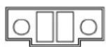
Fig. 16. Terminal block for connection to the inverter shutdown auxiliary contact of the manual bypass board.
5.2.8. Connection in parallel, only in models with power ratings > 3 kVA.
5.2.8.1. Introduction in redundancy.
N+X is usually the most reliable power structure. N represents the minimum number of devices that the total load needs; X represents the number of redundant devices, that is, the number of faulty UPSs that the system can simultaneously allow. The higher X is, the greater the reliability of the system. For occasions where reliability is essential, N+X will be the optimum mode.
Up to 3 devices can be connected in parallel to configure a shared output or power redundancy.
5.2.8.2. Installation and operation in parallel.
- The communications line -COM- constitutes a very low voltage safety circuit. To preserve the quality must be installed separately from other lines carrying dangerous voltages (power distribution line).
• Parallel connections and current signal bus.
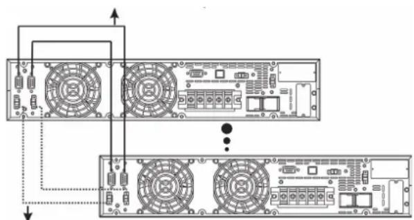
Use the 15-wire signal cable with mesh and DB15 connectors at the ends to connect a maximum of 3 devices. Each cable has a male and a female connector at the ends which must be connected to link two devices. It is essential to close the communications loop of the parallel bus and the current signal bus through the cable with connectors (see Fig. 17).
The length of the cables related to the parallel bus is approx. 1.5 metres and must not be prolonged under any circumstances due to the risk of interference and communication failures that this would entail.
Communication bus.
natural_image
Diagram of a dual-chamber electronic device showing front and rear views with fan and circuit components (no text or labels)Current signal bus
Fig. 17. Communication and current signal connections for system in parallel.
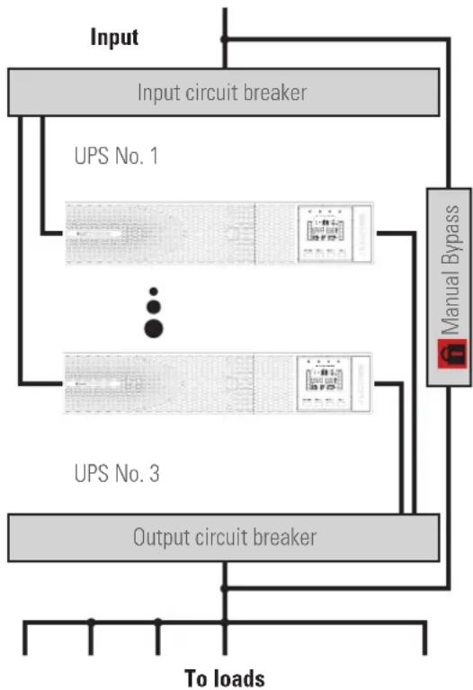
- When installing systems in parallel, it is necessary to provide them with a board equipped with individual input and output protections, as well as a manual bypass with mechanical locking, see Fig. 18.
This protections board will enable a single device in the system to be isolated in the event of a fault and the loads to be powered with the rest during preventive maintenance or repair. It also allows the removal of a device in parallel and its replacement or reintegration once repaired without interrupting the powering of the loads at any time, provided that the power of the operational device permits it. Upon request, we can supply a manual bypass board for a two-device system in parallel.
- Follow the connection procedure for the input described in section 5.2.1.
- Follow the connection procedure for the output (loads) described in section 5.2.2.
- Follow the procedure established for the connection of the battery module or devices with backup extension described in section 5.2.3.
flowchart
graph TD
    A["Input"] --> B["Input circuit breaker"]
    B --> C["UPS No. 1"]
    B --> D["UPS No. 3"]
    C --> E["Manual Bypass"]
    D --> E
    E --> F["Output circuit breaker"]
    F --> G["To loads"]
    style A fill:#f9f,stroke:#333
    style B fill:#ccf,stroke:#333
    style C fill:#cfc,stroke:#333
    style D fill:#cfc,stroke:#333
    style E fill:#fcc,stroke:#333
    style F fill:#cff,stroke:#333
    style G fill:#ffc,stroke:#333
Fig. 18. Parallel installation of two 4 to 10 kVA UPSs with protections panel and manual bypass.
- In parallel systems, the length and cross section of the cables that run from the protections board to each UPS and from the UPSs to the board will be the same for all of them without exception. In the worst case, the following deviations must be strictly observed:
☐ When the distance between the UPSs in parallel and the circuit breaker board is less than 20 metres, the difference in length between the input and output cables of the device must be less than 20%.
☐ When the distance between the UPSs in parallel and
the circuit breaker board is more than 20 metres, the difference in length between the input and output cables of the device must be less than 10%.
5.2.9. Communication port.
5.2.9.1. RS232 and USB port.
- The communications line -COM- constitutes a very low voltage safety circuit. To preserve the quality must be installed separately from other lines carrying dangerous voltages (power distribution line).
- The RS232 and USB interfaces are useful for the monitoring software and updating the firmware.
- It is not possible to use both the RS232 and USB ports at the same time.
- The DB9 connector supplies the RS232 signals and, in models up to 3 kVA, the normally open (NO) potential-free contacts using optocouplers.
The maximum voltage and current applicable to these contacts is 30V DC and 1A.
Also, there is a «Shutdown» input that allows turning off the inverter, when a voltage between 10 a 12 V is applied for 1 second at this input.
- The RS232 port consists of the transmission of serial data in such a way that a large amount of information can be sent through a communication cable with only 3 wires.
- The USB port is compatible with the USB 1.1 protocol for communication software.
| Pin # Description / Input / Output | ||
| 1 End of backup Output | ||
| 2 | TXD for RS232 | Output |
| 3 | RXD for RS232 | Input |
| 4 | GND for shutdown | Earth |
| 5 | GND for RS232 | Earth |
| 6 | Common relays | - |
| 7 | Shutdown order | Input |
| 8 | Low battery Output | |
| 9 | Mains fault | Output |
Tab. 3. Pinout of DB9 connector, RS232.
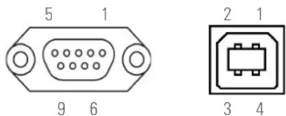
Fig. 19. DB9 connectors for RS232 and USB.
5.2.10. Smart slot for the integration of an electronic communication unit.
- Optional electronic communication units include:
☐ Interface to relays to terminals, not programmable.
SNMP adapter.
Modbus RS485 adapter.
- The corresponding documentation is supplied with each option. Read it before starting installation.
Installation.
- Remove the protective cover from the device's slot.
- Take the corresponding electronic unit and insert it into the reserved slot. Make sure that it is properly connected, for which it is necessary to overcome the resistance caused in the connector located in the slot.
- Make the necessary connections in the terminal block or connectors available according to each case.
- Fit the new protective cover supplied with the interface to relays card and secure it with the screws from the old cover.
- For more information, contact our T.S.S. or our nearest distributor.
5.2.11. Protection against voltage spikes for the modem / ADSL / fax, etc., line.
- The communications line -COM- constitutes a very low voltage safety circuit. To preserve the quality must be installed separately from other lines carrying dangerous voltages (power distribution line).
- Connect the main line for the modem / ADSL / fax, etc., to the RJ45 connector of the device, identified as 'Input'.
- Connect the modem / ADSL / fax, etc., to the RJ45 connector of the device, identified as 'Output'.
5.2.12. Software.
• Download of free ViewPower software.
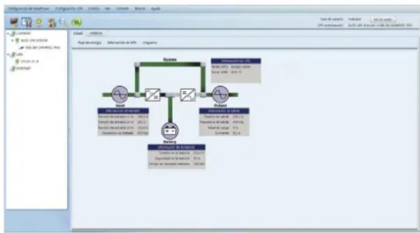
ViewPower is a UPS monitoring software which provides a user-friendly interface for monitoring and control. It features an auto shutdown function for systems consisting of several PCs in case of power failure. The software enables users to monitor and control any UPS in the same LAN through an RS232 or USB communications port, regardless of how far away they are from each other.
flowchart
graph TD
    A["User"] --> B["Database"]
    B --> C["Database Node 1"]
    B --> D["Database Node 2"]
    B --> E["Database Node 3"]
    C --> F["Data Source: Data"]
    D --> G["Data Source: Data"]
    E --> H["Data Source: Data"]
    F --> I["Data Source: Data"]
    G --> J["Data Source: Data"]
    H --> K["Data Source: Data"]
    I --> L["Data Source: Data"]
    J --> M["Data Source: Data"]
    K --> N["Data Source: Data"]
    L --> O["Data Source: Data"]
    M --> P["Data Source: Data"]
    N --> Q["Data Source: Data"]
    O --> R["Data Source: Data"]
Fig. 20. View of ViewPower's main screen.
• Installation procedure:
☐ Go to the web page:
http://support.salicru.com
☐ Select the required operating system and follow the instructions described on the web page to download the software.
5.2.13. Considerations before start-up with connected loads.
- In is recommended to charge the batteries for at least 12 hours before using the UPS for the first time.
☐ For this, it will be necessary to supply voltage to the device and turn the circuit breaker at the back to 'On'. The battery charger will work automatically.
☐ For the battery modules.
For the models with batteries external to the device or backup extension modules, it will also be necessary to turn the fuse or circuit breaker of the batteries arranged between each one to 'On'.
- Although the device can operate correctly without charging the batteries for the specified 12 hours, the risk of a prolonged power cut during the first hours of operation and the UPS's available backup time should be assessed.
- Do not start up the device and loads completely until indicated in Chapter 6.
When it is done, however, it should be carried out gradually to avoid possible difficulties, if not at the first start-up.
- If, in addition to the more sensitive loads, it is necessary to connect high-consumption inductive loads, such as for laser printers or CRT monitors, the starting up of these peripherals will need to be taken into account to prevent the device from crashing.
For this type of load considered NON-PRIORITY, a group of programmable terminals is available depending on the model. Depending on the programming of these, the power supply may or may not be affected in the event of mains failure.
6. OPERATION.
6.1. START-UP.
6.1.1. Checks before start-up.
- Make sure that all of the connections have been made correctly and with sufficient tightening torque, following the instructions on the labelling of the device and in Chapter 5.
- Check that the UPS and battery module or modules switches are 'Off'.
• Make sure that all loads are 'Off'.
Shut down the connected loads before starting the UPS and start the loads, one by one, only when the UPS is running. Before shutting down the UPS, check that all of the loads are 'Off'.
• It is very important to proceed in the established order.
• For views of the UPS, see Fig. 1 to Fig. 3.
- In Fig. 18, a distribution board with manual bypass is represented conceptually for a parallel system, representative for a single device, with the number of switches adapted.
6.2. UPS START-UP AND SHUTDOWN.
6.2.1. UPS start-up with mains voltage.
- Check that the power connection is correct.
- Supply voltage to the device (turn the input protection on the distribution board or manual bypass to 'On'. If the board has an output switch, turn it to 'On'.
- Turn the battery switch to 'On' (models B0 and B1).
- In 4 to 10 kVA models, turn the UPS's input circuit breaker located at the back of the device to 'On'.
The output terminals will have voltage through the device's internal static bypass block.
The fan or fans, depending on the model, will start to function.
Then the main start screen will be displayed after a test of the device.
- Press the 'ON' button for more than 2 seconds, the audible alarm will sound for 1 second and the UPS will start up.
- The UPS is set to 'Normal mode' after a few seconds. If the mains voltage is incorrect, the UPS will switch to 'Battery mode', without interrupting the power supply at the output terminals.
- Start the load or loads, making sure that the rated power of the device is not exceeded.
6.2.2. UPS start-up without mains voltage.
- If it has a distribution board, turn the input and output protections to 'On'.
- Turn the battery switch to 'On' (models B0 and B1).
- Turn the device's input circuit breaker to 'On'.
- Press the 'ON' button for more than 2 seconds, the audible alarm will sound for 1 second and the UPS will start up. The fan or fans, depending on the model, will start to function.
Then the main start screen will be displayed after a test of the device.
On the 4 to 10 kVA models, it is necessary to press the 'ON' button for a second time, about 5 to 7 seconds after the first press, for longer than 2 seconds.
- The UPS is set to 'Battery mode' after a few seconds.
Depending on the level of charge of the batteries, the residual backup available may be very limited. Consider the risk involved in operating without mains and discharged batteries.
If the mains voltage returns, the UPS will transfer to 'Normal mode' without interrupting the power supply at the output terminals.
- Start the load or loads, making sure that the rated power of the device is not exceeded.
6.2.3. UPS shutdown with mains voltage.
- Shut down the load or loads.
- Press the 'OFF' button for more than 2 seconds to shut down the inverter. The audible alarm will sound for 1 second. The device will be set to 'Bypass mode'.
The output terminals will have voltage through the device's internal static bypass block.
• To cut the UPS's output voltage:
☐ Disconnect the input plug of the power socket on models up to 3 kVA and from 4 to 10 kVA and turn the input circuit breaker located at the back of the device to 'Off'.
Or simply turn the input and output protections of the UPS's distribution board on any model to 'Off'.
A few seconds later, the LCD screen turns off and the entire device will be out of service.
6.2.4. UPS shutdown without mains voltage.
- Shut down the load or loads.
- Press the 'OFF' button for more than 2 seconds to shut down the inverter. The audible alarm will sound for 1 second. The device will leave the output terminals without voltage. A few seconds later, the LCD screen turns off and the entire device will be out of service.
- To leave the assembly completely isolated, turn the input and output switches of the board to 'Off'.
6.3. OPERATING PROCEDURE FOR A PARALLEL SYSTEM (ONLY IN 4 TO 10 KVA MODELS).
- In parallel systems, check that the programming of Output 2 is the same on all of them to avoid conflicts.
- The operating procedure established here is for devices with a configuration determined by factory default.
- Check that the load or loads and/or the output circuit breakers on the distribution board are 'Off'.
- Turn "On" the input circuit breakers on the distribution or manual bypass board and those on each UPS in 4 to 10 kVA. The UPSs supply output voltage from the internal static bypass of each unit. Observe the LCD screen of the control panel for any warnings or error information. Measure the output voltage at the terminals of each UPS separately to check that the voltage difference between them is less than 1 V. If the difference is greater than 1 V, check the connection and the associated instructions.
- If everything is correct, proceed. Press the 'ON' button on all of the UPSs for more than 2 seconds and each of them will start up. All of the UPSs will transfer to 'Normal mode'. Measure the output voltage at the terminals of each UPS separately to check that the voltage difference between them is less than 0.5 V. If the difference is greater than 1 V, the UPSs will need to be adjusted (contact T.S.S.).
- If everything is correct, proceed. Press the 'OFF' button for more than 2 seconds on all of the UPSs and each of them will begin to shut down the device.
Turn the input circuit breakers on the distribution or manual bypass board to 'On'. The output terminals on the distribution board will be under potential through the static bypass of the device.
- Press the 'ON' button for more than 0.5 seconds on all of the UPSs and each one of them will begin to start up in order to finally leave the system in parallel operation in 'Normal mode'.
- Start the load or loads.
- Do not leave a floating UPS with respect to the others. There must always be a connection between the neutrals, either input or output. Do not open the input and output circuit breakers of a UPS at the same time on the distribution board while the UPS running. Otherwise, a fault in the UPS may occur and the connected loads may shut down
6.4. HOW TO ADD A UPS TO A SYSTEM IN PARALLEL OPERATION OR TO A FUNCTIONING SINGLE UPS (ONLY IN 4 TO 10 KVA MODELS).
- To operate the parallel system, it is necessary to have a manual bypass board for the parallel system. In the event of not having one, the shutdown of the entire system and the loads powered by it must be anticipated.
- The steps to follow are for the addition of a device to a system with two units. To incorporate a device into a system with only one UPS, proceed in the same way.
- The distribution board must have input and output switches for each UPS, in addition to the one for the manual bypass. Otherwise, it will be necessary to adapt the board or acquire a new one if it has not been previously anticipated.
- Since it is necessary to change the parallel bus connection to incorporate the new device into the system (cable with DB15 connectors), it will be necessary to switch the powering of the loads to the manual bypass.
Proceed as follows:
☐ Press the 'OFF' button on all of the UPSs for more than 2 seconds to shut down the inverter in all of them. The audible alarm will sound for 1 second. The devices that make up the current parallel system will switch to 'Bypass mode'.
☐ Switch the devices to manual bypass using the following procedure:
-
Remove the mechanical lock on the distribution board's manual bypass switch or disconnector and turn it to 'On'.
-
Remove the protective cover of the manual bypass switch, which is located at the back of each unit, and turn all of the switches to 'BYPASS'.
Take into consideration that in 'Bypass mode' or with the switch turned to 'BYPASS', the loads will be exposed to voltage and frequency variations and cuts or micro-cuts in mains power, so, if possible, it is recommended to choose a day with lower probability of failure (days without fluctuations, days without storms, etc.) and a certain speed in the process.
☐ Turn the input circuit breakers of each device to 'Off'.
☐ Turn the input and output circuit breakers of the board to 'Off'.
- Before incorporating the new TWIN RT2 into the system, carry out the appropriate steps to leave it in the same condition as the others (input switch turned to 'Off' and manual bypass switch without protective cover turned to 'BYPASS').
- Incorporate the new UPS to the system following the procedure established in section 5.2.8.2 for connection in parallel.
- Disconnect the communication bus between the first and last device, and reconnect it including the new UPS. The bus must be closed for proper operation.
- Turn the input circuit breakers of each UPS on the distribution board to 'On'.
- Turn the input circuit breakers of each UPS to 'On'. Turn the internal manual bypass switch of each UPS to UPS. The output switches of each UPS on the distribution board must be open.
Fit the switch lock cover of each UPS
The UPSs supply output voltage from the internal static bypass of each unit. Observe the LCD screen of the control panel for any warnings or error information. Measure the output voltage at the terminals of each UPS separately to check that the voltage difference between them is less than 1 V. If the difference is greater than 1 V, check the connection and the associated instructions.
- If everything is correct, proceed. Press the 'ON' button on all of the UPSs for more than 2 seconds and each of them will start up. All of the UPSs will transfer to 'Normal mode'. Measure the output voltage at the terminals of each UPS separately to check that the voltage difference between them is less than 0.5 V. If the difference is greater than 1 V, the UPSs will need to be adjusted (contact T.S.S.).
- If everything is correct, proceed. Press the 'OFF' button on all of the UPSs for more than 2 seconds and each of them will begin to shut down the device.
Turn the output circuit breakers on the distribution board to 'On'. The output terminals on the board will be under potential through the static bypass of the devices, the same potential as the manual bypass line. - Turn the manual bypass switch or disconnector on the distribution board to 'Off' and reposition the mechanical lock to prevent possible accidents
- To prevent incorrect operations, it is necessary to fit the mechanical lock and the covers of the manual bypass mechanisms and their fixing screws.
- Press the 'ON' button on all of the UPSs for more than 2 seconds and each of them will start up, in order to finally leave the system in parallel operation in 'Normal mode'.
- The load or loads are again protected by the parallel system.
6.5. HOW TO REPLACE A FAULTY UPS IN AN OPERATIONAL PARALLEL SYSTEM.
- The steps to follow to replace a UPS in a system consisting of two or three units are the same as those for incorporating a device, except for the difference in the type of action to be carried out. Proceed therefore as described in section 6.4.
7. CONTROL PANEL WITH LCD DISPLAY.
7.1. GENERAL INFORMATION FOR THE SERIES.
7.1.1. Information represented by the display.
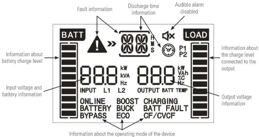
Fig. 21. Graphic and textual information shown on the display.
7.1.2. Common messages shown on the LCD display.
| Display Meaning | |
| Backup time information. | |
 | Indicates the backup time in analogue clock mode. |
 | Indicates the backup time in digital clock mode.H - Hours, M - Minutes, S - Seconds. |
| Fault information. | |
 | Indicates as a warning that a fault has occurred. |
 | Indicates a numerical code from the settings menu shown in Table 9 of Section 7.5. |
| Audible alarm information. | |
 | Indicates that the audible alarm is disabled. |
| Output voltage information. | |
 | Indicates the output voltage or frequency. V AC - Output voltage, Hz - Output frequency. |
| Information about the charge level connected to the output. | |
 | Indicates the charge level connected to the output as a %, by displaying four equivalent segments respectively in the following proportion: 0-25 %, 26-50 %, 51-75 % and 76-100 %. |
| Information about programmable outputs | |
| P1 | Indicates that the programmable outputs are activated. |
| Information about the operating mode of the device. | |
| BATTERY | Indicates that the device is supplying output voltage from the battery (battery mode). |
| BYPASS | Indicates that the device is activated in BYPASS mode. |
| ECO | Indicates that the device is supplying output voltage from the bypass (ECO mode). |
| CHARGING | Indicates that the device is in charging mode. |
| CF/CVCF | Indicates that the device is in converter mode. |
| ONLINE | Indicates that the inverter is working. |
| P1 | Indicates that the output is activated. |
| Information about battery charge level. | |
| [28CX] | Indicates the battery charge level as a %, by displaying four equivalent segments respectively in the following proportion: 0-25 %, 26-50 %, 51-75 % and 76-100 %. |
 FAU FAU | Indicates that the battery is not connected. |
| Indicates low battery voltage level. | |
Inf  | Indicates the input and battery voltage. |
| INPUT L1 L2 | Indicates the input voltage, frequency or battery voltage. V AC - Input voltage, V DC - Battery voltage, Hz - Input frequency. |
Tab. 4. Information shown on the LCD panel of the control panel and its meaning.
7.1.3. Common abbreviations shown on the display.
| Code Or | display Meaning | |
| ENA |  | Enabled. |
| DIS |  | Disabled. |
| ATO |  | Automatic. |
| BAT |  | Battery. |
| NCF |  | Normal mode, working mode as UPS. |
| CF |  | Working mode as frequency converter. |
| SUB |  | Subtract. |
| ADD |  | Add. |
| ON |  | Start-up. |
| OFF |  | Shutdown. |
| FBD |  | Not permitted. |
| OPN |  | Permitted. |
| RES |  | Reserved. |
| N.L |  | Neutral lost. |
| CHE |  | Check. |
| OP.V |  | Output voltage |
| PAR |  | Parallel, 001 refers to the first. |
| EPO |  | Emergency power off. |
| FR |  | Frequency. |
| OPL |  | Load percentage. |
| ESC |  | Escape. |
| HLS |  | Upper voltage limit for transfer to battery mode. |
| LLS |  | Lower voltage limit for transfer to battery mode. |
| AO |  | EPO normally open. |
| AC |  | EPO normally closed. |
| EAT |  | Estimated backup time. |
| Code Or | display Meaning | |
| RAT | tA t | Current time in backup mode. |
| Ok | OK | Ok. |
| SD | Sd | Shutdown. |
| BL | bL | Low battery. |
| OL | OL | Overload. |
| OI | OI | Input overcurrent |
| NC | NC | Battery not connected |
| OC | OC | Battery overcharge |
| SF | SF | Connection error. Rotate the connection of the input, phase and neutral cables. |
| TP | TP | Overtemperature. |
| CH | CH | Charger |
| BF | bF | Battery failure, low voltage. |
| BV | bV | Bypass voltage out of range. |
| FU | FU | Bypass frequency out of range. |
| BR | BR | Replace batteries. |
| EE | EE | Internal EEPROM error. |
Tab. 5. Abbreviations shown on the LCD display.
7.2. CONTROL PANEL FOR MODELS UP TO 3 KVA.
7.2.1. Composition of the control panel with LCD display.
• The control panel consists of:
☐ Three buttons with the functions described in Tab. 6.
☐ An LCD display with backlighting.
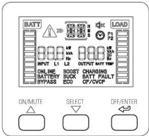
Fig. 22. View of the control panel.
| Button Description | |
| ON/MUTE | - Starting up the UPS.Press the button for at least 2 seconds.- Muting the alarm.Press the button for at least 3 seconds to mute or unmute the audible alarm.It is only possible to mute the battery discharge alarm, which necessarily means that the device is running and operating in battery mode. Any other warning or error alarm cannot be muted.- Button to navigate upwards.When this button is pressed in UPS settings mode, it will move upwards through the menu structure in relation to the point where it is located, accessing the previous variable with each press.- Activating the battery test.Press this button for 3 seconds while in normal or frequency converter (CF) mode. At the end of the test, it returns to the respective mode. |
| SELECT | - Settings or configuration mode.Press this button for at least 3 seconds to access this mode when the inverter of the UPS is shut down (bypass mode).- Button to navigate downwards.When this button is pressed in UPS settings mode, it will move downwards through the menu structure in relation to the point where it is located, accessing the following variable with each press. |
| OFF/ENTER | - UPS shutdown.Press this button for at least 2 seconds.- Confirmation of selection.Press this button to confirm selection in the device's settings mode. |
Tab. 6. Functionality of the control panel buttons.
7.2.2. Audible alarms.
| Description Alarm | modulation or tone | Possibility of muting |
| State of the UPS | ||
| Bypass mode Beep every 10 seconds. | YesBattery mode Beep ever | |
| Fault Continuous. | ||
| Warning | ||
| Overload Beep every second. | Yes | |
| Other Beep every 1 seconds. | ||
| Faults | ||
| All Continuous | Yes | |
Tab. 7. Audible alarms.
7.2.3. Location of the adjustment parameters on the display.

Fig. 23. Arrangement of the parameters on the LCD display.
- Parameter 1:
Code of the settings menu. For more information consult Tab. 8.
- Parameters 2 and 3 are the configuration or value options for each settings menu.

Select with buttons '▽' or '△' to modify the menus or parameters.

All of the parameter settings are saved when the UPS is completely shut down and provided that it connected batteries, whether internal or external.
If a complete shutdown is not carried out, the setting will not be saved to the memory.
7.2.4. Settings.
Tab. 8 shows a summary of parameter 1's adjustable codes for each operating mode and Fig. 24 shows the structure of the menu tree with the operating mode for the settings.
| Code Description | Bypass mode/No output mode | AC mode ECO mode CF mode | Battery mode | Battery test | |||
| 01 Output voltage. YES ---- | |||||||
| 02 Frequency converter state. YES ---- | |||||||
| 03 Output frequency. YES ---- | |||||||
| 04 ECO enable/disable mode. YES ---- | |||||||
| 06 | Bypass state (UPS 'Off'). | YES | YES | - | - | - | - |
| 09 | Programmable output state. | YES | YES | YES | YES | YES | YES |
| 10 | Programmable output configuration. | YES | YES | YES | YES | YES | YES |
| 11 | Backup limitation configuration. | YES | YES | YES | YES | YES | YES |
| 12 | Total battery pack Ah configuration. | YES | YES | YES | YES | YES | YES |
| 15 | EPO logical configuration. | YES | YES | - | YES | YES | - |
| 17 | Viewable backup time configuration. | YES | |||||
Tab. 8. Parameter 1 codes list. Description and settings
7.2.4.1. Ah configuration of parameter '12'.
- Standard models are configured with factory default settings, so it is not necessary to perform any actions to adjust this parameter.
For extended backup and B1 models, however, it is necessary to adjust the value to the total capacity of the battery pack. Any alteration of the battery pack will entail a readjustment, so it will be necessary to adapt the value in the event of future expansions.
- There are basically two reasons to perform the adjustment without it affecting the correct functioning of the device if it is not done, although it is more than recommended:
a. The charging current of the batteries is directly related to the capacity of the battery pack.
The charger will adapt the charging factor automatically according to the value of the total capacity entered, up to the maximum of the current that is possible.
This results in faster charging and therefore greater availability and more immediate backup in the event of frequent mains failures.
b. Entering the value in Ah is vital for the control to be able to calculate and show the backup available on the LCD display, without further alterations.
The settings values are determined as follows:
- Devices with backup extension.
They are configured by a standard model plus the battery module or modules. The capacity of the batteries of both are indicated in the following Tab. 9 and Tab. 10.
Example for an SLC 1500 TWIN RT2 and backup extension module 698BU000003:
9 Ah + 18 Ah = 27 Ah (value for parameter 12).
| UPS model | Internal batteries | |
| Voltage (V) | Capacity (Ah) | |
| SLC 700 TWIN RT2 | 36 | 7 |
| SLC 1000 TWIN RT2 | ||
| SLC 1500 TWIN RT2 | 48 | 9 |
| SLC 2000 TWIN RT2 | ||
| SLC 3000 TWIN RT2 | 72 | |
Tab. 9. Characteristics of batteries in standard devices.
| Battery module | ||
| Code | Voltage (V) | Capacity (Ah) |
| 698BU000001 | 36 | 14 (2 x 7) |
| 698BU000002 | 36 | 18 (2 x 9) |
| 698BU000003 | 48 | |
| 698BU000004 | 72 | |
Tab. 10. Characteristics of batteries in modules.
- Device B1.
B1 models do not have batteries in the same box, so a battery module will always be necessary or the user will have them.
Example for an SLC 1500 TWIN RT2 B1 and three backup extension modules 698BU000003:
(3 x 18 Ah) = 54 Ah (value for parameter 12).
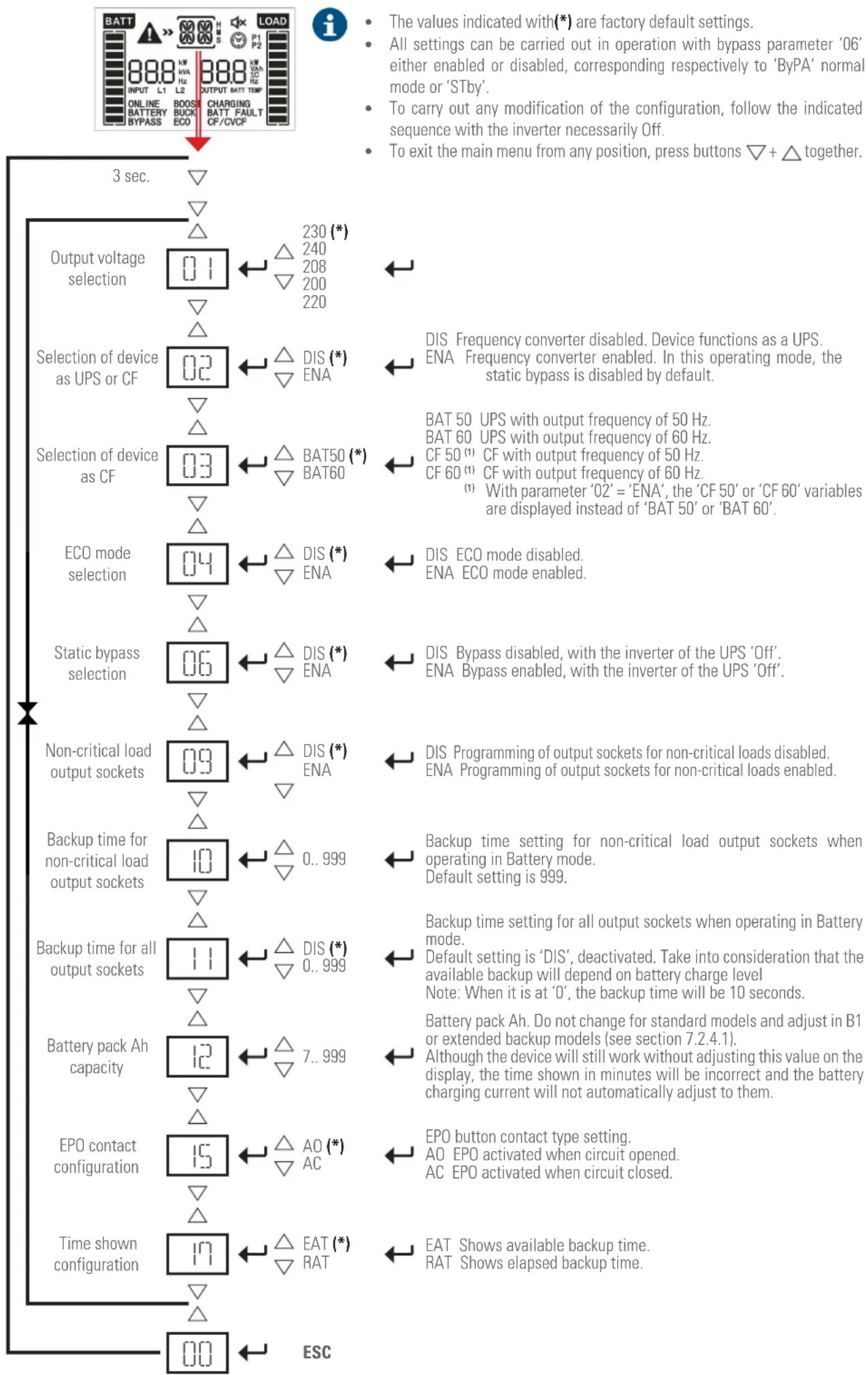
flowchart
graph TD
    A["3 sec."] --> B["Output voltage selection"]
    B --> C["01"]
    C --> D["230 (*)"]
    D --> E["240"]
    E --> F["208"]
    F --> G["200"]
    G --> H["220"]
    H --> I["Selection of device as UPS or CF"]
    I --> J["02"]
    J --> K["DIS (*)"]
    K --> L["ENA"]
    L --> M["DIS Frequency converter disabled. Device functions as a UPS. ENA Frequency converter enabled. In this operating mode, the static bypass is disabled by default."]
    I --> N["Selection of device as CF"]
    N --> O["03"]
    O --> P["BAT50 (*)"]
    P --> Q["BAT60"]
    Q --> R["DIS UPS with output frequency of 50 Hz. BAT 60 UPS with output frequency of 60 Hz. CF 50 (1) CF with output frequency of 50 Hz. CF 60 (1) CF with output frequency of 60 Hz. (1) With parameter '02' = 'ENA', the 'CF 50' or 'CF 60' variables are displayed instead of 'BAT 50' or 'BAT 60'."]
    I --> S["ECO mode selection"]
    S --> T["04"]
    T --> U["DIS (*)"]
    U --> V["ENA"]
    V --> W["DIS ECO mode disabled. ENA ECO mode enabled."]
    I --> X["Static bypass selection"]
    X --> Y["06"]
    Y --> Z["DIS (*)"]
    Z --> AA["ENA"]
    AA --> AB["DIS Bypass disabled, with the inverter of the UPS 'Off'. ENA Bypass enabled, with the inverter of the UPS 'Off'."]
    I --> AC["Non-critical load output sockets"]
    AC --> AD["09"]
    AD --> AE["DIS (*)"]
    AE --> AF["ENA"]
    AF --> AG["DIS Programming of output sockets for non-critical loads disabled. ENA Programming of output sockets for non-critical loads enabled."]
    I --> AH["Backup time for non-critical load output sockets"]
    AH --> AI["10"]
    AI --> AJ["0..999"]
    AJ --> AK["Backup time setting for non-critical load output sockets when operating in Battery mode. Default setting is 999."]
    I --> AL["Backup time for all output sockets"]
    AL --> AM["11"]
    AM --> AN["DIS (*)"]
    AN --> AO["0..999"]
    AO --> AP["Backup time setting for all output sockets when operating in Battery mode. Default setting is 'DIS', deactivated. Take into consideration that the available backup will depend on battery charge level Note: When it is at '0', the backup time will be 10 seconds."]
    I --> AQ["Battery pack Ah capacity"]
    AQ --> AR["12"]
    AR --> AS["7..999"]
    AS --> AT["Battery pack Ah. Do not change for standard models and adjust in B1 or extended backup models (see section 7.2.4.1). Although the device will still work without adjusting this value on the display, the time shown in minutes will be incorrect and the battery charging current will not automatically adjust to them."]
    I --> AU["EPO contact configuration"]
    AU --> AV["15"]
    AV --> AW["AO (*)"]
    AW --> AX["AC"]
    AX --> AY["EPO button contact type setting. AO EPO activated when circuit opened. AC EPO activated when circuit closed."]
    I --> AZ["Time shown configuration"]
    AZ --> BA["17"]
    BA --> BB["EAT (*)"]
    BB --> BC["RAT Shows available backup time."]
    I --> BD["ESC"]
Fig. 24. Settings menu.
7.2.4.2. Operating mode / Description of state.
| Operating mode / state | |||
| UPS start-up | Description. | When the UPS is started, the display screen of this mode is displayed for a few seconds to initialise the CPU and system. | |
| LCD display. | 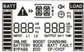 | ||
| No output mode | Description. | The UPS is off and no output voltage is available, but it is charging the batteries. | |
| LCD display. | 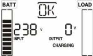 | ||
| AC mode | Description. | If the input voltage is within the range of the device, the UPS will supply stable AC sine-wave voltage to the load or loads, and charge the batteries. | |
| LCD display. |  | ||
| ECO mode | Description. | If the input voltage is within the regulation ranges and ECO mode is activated, the UPS supplies the output voltage from the bypass in ECO mode (energy saving). | |
| LCD display. |  | ||
| CF mode | Description. | When the input frequency is between 46 and 64 Hz, the UPS can be set to a constant output frequency of 50 or 60 Hz. The device will still charge the batteries in this mode. | |
| LCD display. |  | ||
| Battery mode | Description. | Description: When the input / frequency voltage is not within the predefined range of the device or there is an AC mains failure, the UPS powers the loads from the batteries for a limited time due to their own capacity and activates the audible alarm modulated every 5 seconds. | |
| LCD display. |  | ||
| Bypass mode | Description. | When the input voltage is within the range but the UPS is overloaded, the system will automatically transfer to bypass mode or the transfer to this mode can be forced through the front panel. The audible alarm beeps every 10 seconds. | |
| LCD display. |  | ||
| Error or fault state | Description. When an error occurs, the ERROR icon and the fault code are displayed. | ||
| LCD display. | 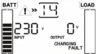 | ||
Tab. 11. Operating modes.
7.2.4.3. Warning or alert codes.
| Code Warning or alert description | |
| b1 | Low battery |
| O1 | Overload |
| O1 | Input overcurrent |
| NC | Battery not connected |
| OC | Battery overcharge |
| SF | Input socket connection fault |
| EP | EPO enabled |
| YP | Overtemperature |
| CH | Charger fault |
| bF | Battery fault |
| bV | Static bypass voltage out of range |
| FU | Unstable static bypass frequency |
| bR | Replace batteries |
| EE | EEPROM error |
Tab. 12. Warning or alert code.
7.2.4.4. Error or fault codes.
| Code Error or fault description | |
| 01 DC bus start-up fault. | |
| 02 DC bus overvoltage. | |
| 03 DC bus undervoltage. | |
| 11 Inverter soft start fault | |
| 12 High voltage in the inverter | |
| 13 Low voltage in the inverter | |
| 14 Inverter output short-circuited | |
| 27 Battery voltage too high | |
| 28 Battery voltage too low | |
| 2A Battery charger short-circuited at its output | |
| 41 | Overtemperature |
| 43 | Output overload |
| 45 | Charger fault |
| 49 | Input overcurrent |
Tab. 13. Error or fault code.
7.2.4.5. Warning or alert indicators.
| Code | Icon (flashing) | Audible alarm |
| Battery voltage low. |  | Modulated every 2 seconds |
| Overload. |  | Modulated every 1 seconds |
| Input overcurrent |  | Modulated twice every 10 seconds |
| Disconnected battery |  | Modulated every 2 seconds |
| Battery overcharge |  | Modulated every 2 seconds |
| Input socket connection fault |  | Modulated every 2 seconds |
| EPO enabled |  | Modulated every 2 seconds |
| Overtemperature |  | Modulated every 2 seconds |
| Charger fault |  | Modulated every 2 seconds |
| Battery fault |  BATT FAULT BATT FAULT | Modulated every 2 seconds (The UPS disconnects to warn the user that the batteries are incorrect). |
| Static bypass voltage out of range |  BYPASS BYPASS | Modulated every 2 seconds |
| Unstable static bypass frequency |  BYPASS BYPASS | Modulated every 2 seconds |
| Replace batteries | [TDBK] | Modulated every 2 seconds |
| EEPROM error |  | Modulated every 2 seconds |
Tab. 14. Warning or alert indicators.
7.3. CONTROL PANEL FOR 4 KVA TO 10 KVA MODELS.
• The control panel consists of:
☐ Four buttons with the functions described in Tab. 15.
A backlit LCD display.
☐ Four optical LEDS (see Tab. 17).
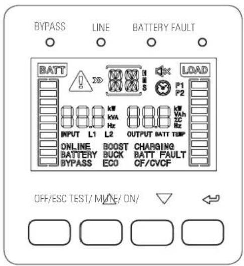
Fig. 25. View of the control panel.
| Button Description | |
| OFF/ESC | - UPS shutdown.Press this button for at least 2 seconds.- ESC functionality.Press this button to return to the last parameter of the settings or configuration menu. |
| TEST/△ | - Activating the battery test.Press this button for 3 seconds while in normal or frequency converter (CF) mode. At the end of the test, it returns to the respective mode.- Button to navigate upwards.When this button is pressed in UPS settings mode, it will move through the menu structure to the following variable in relation to the point where it is located. |
| MUTE/▽ | - Muting the alarm.Press the button for at least 3 seconds to mute or unmute the audible alarm.It is only possible to mute the battery discharge and bypass alarm.- Button to navigate downwards.When this button is pressed in UPS settings mode, it will move through the menu structure to the previous variable in relation to the point where it is located. |
| ON/ ⇌ | - Starting up the UPS.Press the button for at least 2 seconds.- Confirmation of selection.Press this button to confirm selection in the device's settings mode. |
| TEST/△MUTE/▽ | Press and hold the two buttons simultaneously for more than 1 second to enter / exit the settings or configuration menu. |

(CF) Working mode of the UPS as a frequency converter, in the static bypass it is disabled.
Tab. 15. Functionality of the control panel buttons.
7.3.1. Audible alarms.
| Description Alarm | modulation or tone | Possibility of muting |
| State of the UPS | ||
| Bypass mode Beep every 2 minutes. | Yes | |
| Battery mode | Beep every 4 seconds. | |
| Fault | Continuous. | |
| Warning | ||
| Overload | 2 beeps every second. | Yes |
| Other | Beep every 1 seconds. | |
| Faults | ||
| All | Continuous. | Yes |
Tab. 16. Audible alarms.
7.3.2. Optical indications.
| State of the UPS | LEDs | |||
| Bypass (yellow) | Line (green) | Battery (yellow) | Fault (red) | |
| UPS start-up | ● ● | ● | ● | |
| No output mode | ○ | ○ | ○ | ○ |
| Bypass mode | ● | ○ | ○ | ○ |
| AC mode | ○ | ● | ○ | ○ |
| Battery mode | ○ | ○ | ● | ○ |
| CF mode | ○ | ● | ○ | ○ |
| ECO mode | ● ● | ● | ○ | |
| Battery test | ● ● | ○ | ○ | |
| Fault | ○ | ○ | ○ | ● |
●: LED illuminated permanently. ○: LED off.
Tab. 17. Interaction between optical LEDs for the different modes or states of the UPS.
7.3.3. Location of the adjustment parameters on the display.

Fig. 26. Arrangement of the parameters on the LCD display.
- Parameter 1: Code of the settings menu. For more information consult Tab. 18.
- Parameters 2 and 3 are the configuration or value options for each settings menu.

Select with buttons "or" to modify the menus or parameters.

All of the parameter settings are saved when the UPS is completely shut down and provided that it connected batteries, whether internal or external.
If a complete shutdown is not carried out, the setting will not be saved to the memory.
7.3.4. Settings.
Tab. 18 shows a summary of parameter 1's adjustable codes for each operating mode.


DEPENDING ON THE DEVICE'S FIRMWARE VERSION, IT IS POSSIBLE TO SHOW SOME SCREENS IN ADDITION TO THOSE INDICATED IN THIS SECTION.
DO NOT CHANGE THE ORIGINAL FACTORY SETTINGS OF THESE, AS THIS COULD CAUSE FAULTS IN THE UPS, LOADS OR BOTH DEPENDING ON EACH SETTING.
• Code 02 - Output frequency.

Fig. 28.
☐ Parameter 2 setting: Output frequency. It is possible to choose one of the following values: -50 Hz, 60 Hz or ATO.
With ATO selected, the output frequency is auto-detected according to the normal input at the time of connection of the device to the mains.
If it is between 46 and 54 Hz, it will be set at 50 Hz, and, if it is between 56 and 64 Hz, at 60 Hz. The factory default setting is ATO.
☐ Parameter 3 setting: Frequency mode.
Output frequency in CF mode or not CF mode setting. It is possible to choose between two options:
- CF. Sets the UPS to CF mode. With this option activated, the output frequency is set to 50 or 60 Hz
| Code Description | Bypass mode/No output mode | AC mode ECO mode CF mode | Battery mode Battery test | ||||
| 01 Output voltage. YES ---- | |||||||
| 02 | Output frequency. | YES | - | - | - | - | - |
| 05 | ECO enable/disable mode. | YES | - | - | - | - | - |
| 08 | Bypass mode setting. | YES | YES | - | - | - | - |
| 09 | Maximum battery discharge time setting. | YES | YES | YES | YES | YES | YES |
| 10 | Reserved. | Reserved for future options. | |||||
| 11 | Reserved. | Reserved for future options. | |||||
| 12 | Hot standby function | YES | YES | YES | YES | YES | YES |
| 17 | Reserved. | Reserved for future options. | |||||
Tab. 18. Parameter 1 codes list. Description and settings
• Code 01 - Output voltage.
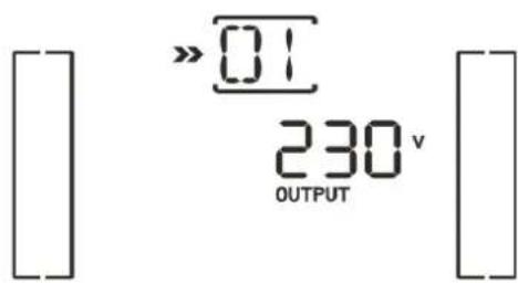
Fig. 27.
☐ Parameter 3 setting: Output voltage. It is possible to choose one of the following values for the output voltage between phase and neutral: -208, 220, 230 or 240 V.
based on the parameter 2 selection. The input frequency can be 46 to 64 Hz.
- NCF. Sets the UPS to normal mode (not CF mode). With this option activated, the output frequency is set at 50 or 60 Hz synchronised with the input frequency based on the parameter 2 selection and its range.
If the parameter 2 selection is 50 or 60 Hz, it will be transferred to battery mode (powering loads) when the frequency is not respectively between 46 and 54 Hz or 56 and 64 Hz.
(*) If ATO is selected in parameter 2, parameter 3 will display the current frequency.

Fig. 29.
• Code 05 - ECO mode selection.

Fig. 30.
☐ Parameter 3 setting: Activates or deactivates the ECO function.
-DIS. ECO function disabled.
-ENA. ECO function enabled.
If the ECO function is disabled, the voltage and frequency range for ECO mode can be adjusted, but there is no point unless the function itself is enabled.
• Code 08 - Bypass mode setting.

Fig. 31.
□ Parameter 2 setting.
-OPN. Bypass permitted. When selecting this option, the UPS will operate in bypass mode, provided that selection in bypass settings (parameter 3) has been enabled/disabled.
-FBD. When selecting this option, operation in bypass mode is not permitted in any condition.
☐ Parameter 3 setting:
-ENA. Bypass enabled. When selected, bypass mode is enabled.
-DIS. Bypass disabled. If selected, automatic bypass is permitted but not manual switch to bypass.
At this point, manual switch to bypass is understood as being that which users perform on the UPS. For example, pressing the OFF button on the front of the device when it is in AC mode transfers the load to the static bypass.
• Code 09 - Maximum battery discharge time setting.

Fig. 32.
☐ Parameter 3 setting:
-000 \~ 999. Sets maximum backup time. The UPS will turn off automatically once it has elapsed to protect the batteries. The default value is 990 minutes (16.5 h).
-DIS. Disables the battery discharge time protection and the backup time will depend on the capacity of the batteries.
• Code 10 - Reserved.

Fig. 33.
Reserved for future options.
• Code 11 - Reserved.

Fig. 34.
☐ Reserved for future options.
• Code 12 - Hot standby function.

Fig. 35.
☐ Parameter 2 setting. HS.H
-Enabling or disabling the Hot standby function.
☐ Parameter 3 setting:
-YES: The Hot standby function is enabled after the mains are restored even without the batteries being connected to the UPS.
- NO: The Hot standby function is disabled. The UPS operates in normal mode. It will not restart if the batteries are not connected to the UPS.
• Code 17 -Battery module number setting.

Fig. 36.
☐ In standard devices with internal batteries or B1 devices, it sets the value to the total number of battery modules including the one belonging to the standard device, unless it is a B1 which does not have accumulators.
- Sets parameter 3 to the number of battery modules. The setting allows values from 0 to 7 and the default setting is 0.
☐ When external batteries are installed independently, equivalence must be found in order to determine the value to be entered in this variable. Proceed as follows to define the value:
- Divide the Ahs of the installed batteries between 7 Ah for the 4 to 6 kVA models and between 9 Ah for the 8 and 10 kVA models. If the value obtained is not exact, round down.
Example:
SLC 5000 TWIN RT2 device with an external battery pack of 45 Ah belonging to it.
45 Ah / 7 Ah = 6.4
When rounding down, value '6' must be entered in parameter 3.
- The basic reason for adjusting the setting is as follows, without it affecting the correct functioning of the device if it is not done, although it is more than recommended:
The charging current of the batteries is directly related to the capacity of the battery pack.
The charger will adapt the charging factor automatically according to the value of the total capacity entered, up to the maximum of the current that is possible.
This results in faster charging and therefore greater availability and more immediate backup in the event of frequent mains failures.
Any alteration of the battery pack will entail a readjustment, so it will be necessary to adapt the value in the event of future expansions.
7.3.4.1. Operating mode / Description of state.
- In correctly configured parallel UPS systems, the acronym 'PAR' will be displayed in the place of the parameter 2 variable and the number corresponding to the device of the system in parallel in parameter 3. The 'MASTER' UPSs will be assigned as '001' by default and the slaves '002' and '003' respectively. The assigned numbers can be modified dynamically during operation.

Fig. 37. Parallel system screen.
7.3.4.2. Operating mode / Description of state.
| Operating mode / state | ||||
| UPS start-up | Description. | When the UPS is started, the display screen of this mode is displayed for a few seconds to initialise the CPU and system. | ||
| LCD display. |  | |||
| No output mode | Description. | If the bypass voltage / frequency is out of range or the bypass is disabled (or prohibited), the UPS will enter no output mode with the inverter running or shut down. The UPS does not supply output voltage. The audible alarm modulated every two minutes is audible. | ||
| LCD display. | 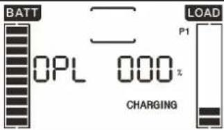 | 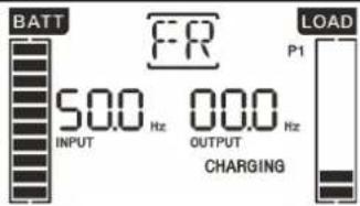 |  | |
| AC mode | Description. | If the input voltage is within the range of the device, the UPS will supply stable AC sine-wave voltage to the load or loads, and charge the batteries. | ||
| LCD display. | 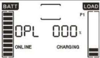 | 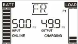 |  | |
| ECO mode | Description. | If the input voltage is within the regulation ranges and ECO mode is activated, the UPS supplies the output voltage from the bypass in ECO mode (energy saving). | ||
| LCD display. |  |  | 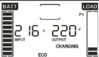 | |
| CF mode | Description. | When the output frequency is selected as CF in parameter 3 of the settings menu code 02, the inverter supplies a constant output frequency (50 or 60 Hz). In this way, the UPS will not supply bypass output voltage, but will charge the batteries. | ||
| LCD display. |  | 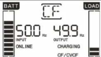 |  | |
| Battery mode | Description. | When the input / frequency voltage is not within the predefined range of the device or there is an AC mains failure, the UPS powers the loads from the batteries for a limited time due to their own capacity and activates the audible alarm modulated every 4 seconds. | ||
| LCD display. | 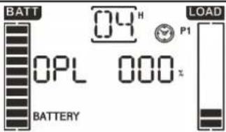 | 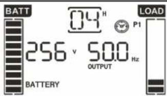 | 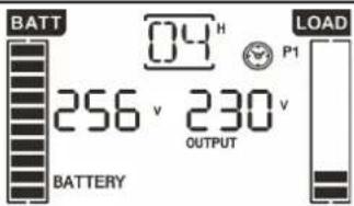 | |
| Bypass mode | Description. | When the input voltage is within the predefined range of the device and the bypass is enabled, when the UPS is switched off, the device enters bypass mode. The audible alarm modulated every two minutes is activated. | ||
| LCD display. | 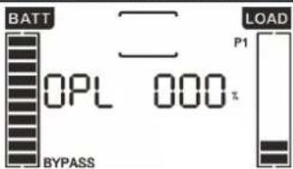 |  | 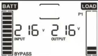 | |
| Battery test | Description. |  | ||
| LCD display. |  |  |  | |
| Error or fault state | TWIN RT2 4-10kVA | When an error or fault is detected in the UPS, the inverter will lock. The fault code will be displayed on the screen and the icon will illuminate. Table 13 shows the error or fault codes and the correlation with the description. | ||
 |  |  | ||
Tab. 19. Operating modes.
7.3.4.3. Warning or alert codes.
| Code Warning or alert description | |
| 01 | Disconnected battery. |
| 07 | Overcharge in the battery. |
| 08 | Low battery. |
| 09 | Output overload. |
| 0A | Fan fault. |
| 0B | EPO activated. |
| 0D | Overtemperature. |
| 0E | Charger fault. |
| 10 | L1 input fuse open. |
| 21 | Line voltages of UPSs connected in parallel are different |
| 22 | Bypass voltages of UPSs connected in parallel are different |
| 33 | UPS locked in bypass after 3 successive overloads in 30 minutes |
| 3A | Maintenance switch cover open |
| 3D | Bypass not available |
| 3E | Start-up fault |
Tab. 20. Warning or alert code.
7.3.4.4. Error or fault codes.
| Code Error or fault description |
| 01 DC bus start-up fault. |
| 02 DC bus overvoltage. |
| 03 DC bus undervoltage. |
| 04 DC bus imbalance. |
| 11 Inverter soft start fault |
| 12 High voltage in the inverter |
| 13 Low voltage in the inverter |
| 14 Inverter output short-circuited |
| 1A Negative power fault at the output. |
| 21 Battery thyristor short-circuited. |
| 24 Inverter relay short-circuited. |
| 2A | Battery charger short-circuited at its output |
| 31 | CAN communication fault |
| 35 Parallel cable fault | |
| 36 Parallel communication fault | |
| 41 | Overtemperature |
| 42 | CPU communication fault |
| 43 | Output overload |
| 6A Battery start-up fault | |
| 6B | PFC current fault in battery mode |
| 6C DC Bus voltage change too fast | |
Tab. 21. Error or fault code.
7.3.4.5. Warning or alert indicators.
| Code | Icon (flashing) | Audible alarm |
| Battery voltage low. |  | Modulated every 1 seconds |
| Overload. |  | Modulated twice every 1 seconds |
| Disconnected battery. |  BATT FAULT BATT FAULT | Modulated every 1 seconds |
| Battery overcharge |  | Modulated every 1 seconds |
| EPO activated. |  | Modulated every 1 seconds |
| Fan fault / Overtemperature |  | Modulated every 1 seconds |
| Charger fault |  CHARGING BATTERY CHARGING BATTERY | Modulated every 1 seconds |
Tab. 22. Warning or alert indicators.
8. MAINTENANCE, WARRANTY AND SERVICE.
8.1. BATTERY MAINTENANCE.
- Pay attention to all of the safety instructions concerning batteries indicated in section 1.2.3. of manual EK266*08. - The service life of the batteries greatly depends on the ambient temperature and other factors such as the number of charges and discharges, as well as their depth.
The service life is designed to be between 3 and 5 years if the ambient temperature to which they are exposed is between 10 and 20°C. Different types of battery with different service lives are available upon request.
- SLC TWIN RT2 series UPSs require minimum upkeep. The batteries used in the standard models are lead acid, sealed, valve regulated and maintenance free. The only requirement is to charge the batteries regularly to extend their life expectancy.
While the UPS is connected to the mains supply, whether or not it is running, it will keep the batteries charged and also offer protection from overcharging and deep discharge.
8.1.1. Notes for the installation and replacement of the battery.
- If it is necessary to replace any connection cables, original materials can be purchased through our T.S.S. or authorised distributors. Using inappropriate cables can lead to overheating in connections, which is a fire hazard.
- Inside the device, there are permanent dangerous voltages even without mains supply present through its connection with the batteries and especially in UPSs where the electronics and batteries share a box.
It is therefore irrelevant if the input circuit breaker of the distribution board and/or that of the input of the device in models with power ratings >3 kVA is turned to 'Off'.
Also take into consideration that the battery circuit is not isolated from the input voltage, so there is a risk of discharge with dangerous voltages between the battery terminals and the earth terminal, which is in turn connected to earth (any metal part of the device).
- Repair and/or maintenance work must be carried out by our T.S.S., except for the replacement of batteries, which can be performed by qualified personnel familiar with them. No other person should handle them.
Depending on the configuration of the UPS, certain actions need to be carried out before handling the batteries:
☐ Devices with batteries and electronics sharing the same box.
-Shut down the loads and device completely.
-Disconnect the SLC TWIN RT2 from the mains.
-Open the device to access the interior.
-Remove the fuse or internal battery fuses.
-Release the battery holders and replace the batteries.
-Perform the above steps in reverse to return the device to how it was at the start, including start-up.
☐ UPS with batteries and electronics in separate boxes.
-Shut down the loads and device completely.
-Disconnect the SLC TWIN RT2 from the mains.
-Disconnect the battery module from the UPS.
-Open the battery module to access the interior.
-Remove the fuse or internal battery fuses.
-Release the battery holders and replace the batteries.
-Perform the above steps in reverse to return the device to how it was at the start, including start-up
8.2. UPS TROUBLESHOOTING GUIDE.
If the UPS does not work properly, check the information shown on the LCD screen of the control panel and act accordingly depending on the device model.
Using the Tab. 23 and Tab. 24 troubleshooting guides, try to resolve the issue and, if it persists, consult our Technical Service and Support T.S.S.
If it is necessary to contact our Technical Service and Support T.S.S., provide the following information:
• UPS model and serial number.
• Date on which the issue occurred.
- Full description of the issue, including information provided by the LCD display or LEDs and state of the alarm.
- Power supply conditions, type of load and level of load applied to the UPS, ambient temperature, ventilation conditions.
- Battery information (capacity and number of batteries), whether the device is a (B0) or (B1).
• Any other information considered relevant.
8.2.1. Troubleshooting guide for devices up to 3 kVA.
| Symptom Possible cause Solution | ||
| No alarms or indications on the LCD display and mains voltage normal. | The power cable is not connected correctly. | Check that the power cables are firmly connected to the mains. |
| The power cable is connected to an IEC output connector on the UPS. | Correctly connect the power cable to the respective IEC connector. | |
Icon  arning code flash on the LCD display and the audible alarm modulated every second is active. arning code flash on the LCD display and the audible alarm modulated every second is active. | The EPO function is activated. Close the EPO signal circuit to deactivate it. | |
| Icon [X3X2]arning code flash on the LCD display and the audible alarm modulated every two seconds is active. | Neutral earth fault detection. Inverted phase and neutral input cables. | Disconnect the input plug from the AC power socket and invert the connection of the phase and the supply neutral (rotate the plug 180°). |
Icon  arning code flash on the LCD display and the audible alarm modulated every two seconds is active. arning code flash on the LCD display and the audible alarm modulated every two seconds is active. | The internal or external batteries are badly connected Check that all batteries are properly connected. | |
| Fault code 27 and theBATT FAULTmessage are shown on the LCD display. The alarm sounds continuously. | The voltage of the batteries is too high or the charger is faulty. | Contact the distributor or seller or, failing that, our T.S.S. |
| Fault code 28 and theBATT FAULTmessage are shown on the LCD display. The audible alarm sounds continuously. | The voltage of the batteries is too low or the charger is faulty. | Contact the distributor or seller or, failing that, our T.S.S. |
| Icon [2K57]warming code flashon the LCD display and the audible alarm modulated every second is active. | The UPS is overloaded. Disconnect the excess loads from the output sockets. | |
| The UPS is overloaded. The connected loads are powered directly from the mains through the Bypass. | Disconnect the excess loads from the output sockets. | |
| After repeated overloads, the UPS is locked in Bypass mode. The connected loads are powered directly from the mains. | Disconnect the excess loads from the output sockets, shut down the device and restart it. | |
| Fault code 49 is shown on the LCD display. The audible alarm sounds continuously. | UPS input overcurrent. Disconnect the excess loads from the output sockets. | |
| Fault code 43 is shown on the LCD display. The audible alarm sounds continuously. | The UPS shuts down automatically as a result of an overload in the output of the device. | Disconnect the excess loads from the output sockets and restart it. |
| Fault code 14 is shown on the LCD display. The audible alarm sounds continuously. | The UPS shuts down automatically as a result of a short circuit in the output. | Check the output wiring and that the connected loads are not short-circuited |
| Fault codes 01, 02, 03, 11, 12, 13 and 41 are shown on the LCD display. The audible alarm sounds continuously. | An internal fault has occurred in the UPS. This is due to one of two possibilities:1. The load is still powered, but directly from the mains through the bypass.2. The load is no longer powered. | Contact the distributor or seller or, failing that, our T.S.S. |
| The backup time is shorter than expected. | The batteries do not charge completely. | Charge the batteries for at least 5 h and then check their charge state. If the problem persists, contact the distributor or seller or, failing that, our T.S.S. |
| Faulty batteries. | Contact the distributor or seller or, failing that, our T.S.S. for battery replacement. | |
| Fault code 2A is shown on the LCD display. The audible alarm sounds continuously. | Charger short-circuited at its output. | Check whether the connection of the external battery pack connected to the UPS is short-circuited. |
| Fault code 45 is shown on the LCD display. At the same time, the audible alarm sounds continuously. | The charger does not provide output and the battery voltage is less than 10 V per element. | Contact the distributor or seller or, failing that, our T.S.S. |
Tab. 23. Troubleshooting guide.
8.2.2. Troubleshooting guide for 4 kVA to 10kVA devices.
| Symptom Possible cause Solution | ||
| No alarms or indications on the LCD display and mains voltage normal. | The power cables are not connected correctly. | Check that the power cables are firmly connected to the mains. |
Icon  Learning code flash Learning code flash  LCD display and the audible alarm sounds every second. LCD display and the audible alarm sounds every second. | The EPO function is activated. Close the EPO signal circuit to deactivate it. | |
Icon  BATT FAULT message flash on the LCD display and the audible alarm sounds every second. BATT FAULT message flash on the LCD display and the audible alarm sounds every second. | The internal or external battery is not correctly connected. Check whether all batteries are correctly connected. | |
[1882]  Icon Learning code flash on LCD display and the audible alarm sounds twice a second. Icon Learning code flash on LCD display and the audible alarm sounds twice a second. | The UPS is overloaded. | Disconnect or shut down the excess loads connected to the UPS output. |
| The UPS is overloaded. The loads connected to the UPS are directly powered by the mains through the bypass. | Disconnect or shut down the excess loads connected to the UPS output. | |
| After repeated overloads, the UPS will transfer to bypass mode. The loads connected to the device will be powered from the input through the bypass. | Disconnect or shut down the excess loads connected to the UPS output, shut down the device and restart it. | |
| Display of fault code 43. Icon up on the LCD display and the audible alarm sounds continuously. | The UPS is overloaded for a long time and the device is locked. The UPS shuts down automatically. | Disconnect or shut down the excess loads connected to the UPS output and restart it. |
| Display of fault code 14, the audible alarm sounds continuously. | The UPS shuts down automatically due to a short circuit at the UPS output. | Check that the output connection and/or the loads connected to it are not short-circuited. |
| One of the following fault codes, 01, 02, 03, 04, 11, 12, 13, 14, 1A, 21, 24, 35, 36, 41, 42 or 43, are displayed on the LCD display and the audible alarm sounds continuously. | An internal fault has occurred in the UPS. This is due to one of two possibilities:1. The load is still powered, but directly from the mains through the bypass.2. The load is no longer powered. | Contact the distributor or seller or, failing that, our T.S.S. |
| The backup time is shorter than expected. | The batteries do not charge completely. | Charge the batteries for at least 7 h and then check their charge state. If the problem persists, contact the distributor or seller or, failing that, our T.S.S. |
| Faulty batteries. | Contact the distributor or seller or, failing that, our T.S.S. for battery replacement. | |
Icon  e TEMP message flash on the LCD display and the audible alarm sounds every second. e TEMP message flash on the LCD display and the audible alarm sounds every second. | The fan is locked or does not work; or the temperature of the UPS is very high. | Check the fans and contact the distributor or seller or, failing that, our T.S.S. |
Tab. 24. Troubleshooting guide.
8.3. WARRANTY CONDITIONS.
8.3.1. Terms of the warranty.
On our website you will find the warranty conditions for the product you have purchased where you can also register it. It is recommended to do so as soon as possible to include it in the database of our Technical Service and Support (T.S.S.). Among other advantages, it will streamline any regulatory procedures for the intervention of T.S.S. in the event of a fault.
8.3.2. Exclusions.
Our company will not be bound by the warranty if it notices that the defect in the product does not exist or was caused by improper use, negligence, improper installation and/or verification, attempts at unauthorized repair or modification, or any other cause beyond the intended use, or by accident, fire,
lightning or other hazards. Nor shall it cover any compensation for damages.
8.4. TECHNICAL SERVICES NETWORK.
Information about our national and international Technical Service and Support (T.S.S.) centres can be found on our website.
9. ANNEXES.
9.1. GENERAL TECHNICAL SPECIFICATIONS.
| Models. TWIN RT2 | ||||||||||
| Available power ratings (kVA / kW). | 0.7 | 1 | 1.5 | 2 | 3 | 4 | 5 | 6 | 8 | 10 |
| Technology. On-line double-conversion, PFC, double DC bus. | ||||||||||
| Rectifier. | ||||||||||
| Input type. Single-phase. | ||||||||||
| Number of cables. | 3 cables - Phase R (L) + Neutral (N) and earth. | |||||||||
| Rated voltage. | 200 / 208 / 220 / 230 / 240 V AC (1) | 208 / 220 / 230 / 240 V AC (2) | ||||||||
| Input voltage range. | 176.. 276 V AC with 100 % load. | |||||||||
| 110.. 300 V AC up to 60 % load. | 110.. 300 V AC up to 50 % load. | |||||||||
| Frequency. | 50 / 60 Hz (auto-detectable) | |||||||||
| Input frequency range. | ±4 Hz (46.. 54 / 56.. 64 Hz) | |||||||||
| Total harmonic distortion (THDi), at full load. | ≤5 % | ≤4 % | ||||||||
| Power factor. | >0.99 (at full load). | |||||||||
| Inverter. | ||||||||||
| Technology. PWM | ||||||||||
| Waveform. | Pure sine wave. | |||||||||
| Power factor. | 1 (3) | |||||||||
| Rated voltage. | 200 / 208 / 220 / 230 / 240 V AC (1) | 208 / 220 / 230 / 240 V AC (2) | ||||||||
| Output voltage accuracy (battery mode). | ±1 % | |||||||||
| Total harmonic distortion (THDv), with linear load. | <1 % | <2 % | ||||||||
| Frequency. | With mains present, synchronised to rated input (46.. 54 / 56.. 64 Hz). | |||||||||
| With mains absent-backup mode- 50 / 60 ±0.1 Hz. | ||||||||||
| Frequency synchronous speed. | <1 Hz/sec. | |||||||||
| Transfer time, inverter to battery. | 0 ms. | |||||||||
| Performance at full load, in line mode with battery 100% charged. | >89 % | >90 % | >91 % | >93 % | ||||||
| Performance at full load, in ECO mode. | >95 % | >96 % | >97 % | >99 % | ||||||
| Overload in line mode. | 110.. 130 %, 5 min. | 100.. 110 %, 2 min. | ||||||||
| >130.. 140 %, 30 sec. | >110.. 130 %, 1 min. | |||||||||
| >140.. 150 %, 1.5 sec. | >130 %, 1 sec. | |||||||||
| >150 %, 100 ms. | - | |||||||||
| Overload in battery mode. | 110.. 130 %, 2 min. | 100.. 110 %, 30 sec. | ||||||||
| >130.. 140 %, 10 sec. | >110.. 130 %, 10 sec. | |||||||||
| >140.. 150 %, 1.5 sec. | >130 %, 1 sec. | |||||||||
| >150 %, 100 ms. | - | |||||||||
| Crest factor. | 3:1 | |||||||||
| Possibility of parallel connection / No. of devices. | Function not available. | Yes / up to 3 UPSs. (4) | ||||||||
| Static Bypass. | ||||||||||
| Type. | Common line with mains. Mixed (thyristors in antiparallel + relay). | |||||||||
| Rated voltage. | That of the mains. | |||||||||
| Rated frequency. | That of the mains. | |||||||||
| Batteries. | ||||||||||
| Element voltage. | 12 V DC | |||||||||
| Capacity. | 7 Ah | 9 Ah | 7 Ah | 9 Ah | ||||||
| Number of batteries in series / group voltage. | 3 / 36 V DC | 4 / 48 V DC | 6 / 72 V DC | 16 / 192 V DC | ||||||
| Blocking voltage for group end of backup. | 31.5 V DC | 42 V DC | 63 V DC | 168 V DC | ||||||
| Internal battery charger. | ||||||||||
| Group fast charge voltage. | 42.5 V DC | 56.6 V DC | 85 V DC | 224 V DC | ||||||
| Group floating voltage. | 41.0 V DC | 54.7 V DC | 81.9 V DC | 218.4 V DC | ||||||
| Maximum charge current. | 4 A | 1 A | ||||||||
| Recharge time. | <3 hours to 90%. | |||||||||
| Voltage / temperature compensation. | 5 mV per battery / °C for temperature >30 °C. | 20 mV per battery / °C for temperature >25 °C. | ||||||||
| Optional internal battery charger (B1). | ||||||||||
| Maximum charge current. | 12 A | 4 A | ||||||||
| Other functions. | ||||||||||
| Cold start. | Yes | |||||||||
| Emergency power off. | Yes | |||||||||
| Frequency converter. | Yes (5) | Yes (6) | ||||||||
| Models. TWIN RT2 | |||||||||||
| Available power ratings (kVA / kW). | 0.7 | 1 | 1.5 | 2 | 3 | 4 | 5 | 6 | 8 | 10 | |
| General. | |||||||||||
| IEC connectors or input terminals. 10 A IEC connector. | 16 A IEC connector, 3 (Phase, neutral and earth terminal). | ||||||||||
| IEC connectors or output terminals. | 8 x 10A IEC (4 + 4) + 1 x 16A IEC (only in 3 kVA UPS) | 3 (Phase, neutral and earth terminal). | |||||||||
| PDU power supply delivered with the device. | - | With 3-wire cable to connect to UPS output terminals. | |||||||||
| IEC output connectors on PDU. | - | 4 x 10A IEC + 2 x 16 A IEC | 2 x 10A IEC + 4 x 16 A IEC | ||||||||
| Communication ports. | 2 (RS232 -DB9- and USB, mutually exclusive). | ||||||||||
| Potential-free contacts, interface to relays. | 3 relays supplied with the same connector as the RS232. | - | |||||||||
| Digital input and output. | - | 1 + 1 | |||||||||
| ADSL/fax/modem transient protector. | Yes (RJ45 connectors) | No | |||||||||
| Monitoring software. | ViewPower (free download). | ||||||||||
| Optional cards (to insert in slot). | Interface to relays, SNMP, remote Internet or intranet management. | ||||||||||
| Noise level at 1 m. | <50 dB | <55 dB | <58 dB | <60 dB | |||||||
| Working temperature. | 0..+40 °C | ||||||||||
| Storage temperature. | -15..+50 °C | ||||||||||
| Working altitude. | 2,400 masl | ||||||||||
| Relative humidity. | 0-95 % non-condensing. | ||||||||||
| Protection rating. | IP20 | ||||||||||
| Dimensions (mm)-Depth × Width × Height- | UPS modules. | 410 x 438 x 88 | 510 x 438 x 88 | 630 x 438 x 88 | 600 x 438 x 88 | ||||||
| Standard battery module. | - | - | - | 688 x 438 x 88 | |||||||
| Optional battery module. | 410 x 438 x 88 | 510 x 438 x 88 | 630 x 438 x 88 | 600 x 438 x 88 | |||||||
| Module height in number of U. | 2 | 2 + 2 | |||||||||
| Weight (kg). | UPS modules. | 14.1 | 14.1 | 15.5 | 19.5 | 27.5 | 17 | 20 | |||
| Battery module. | - | 52 | 54 | ||||||||
| Optional battery module. | 19.1 | 21.5 | 29 | 41.2 | 52 | 54 | |||||
| Safety. EN-IEC 62040-1 | |||||||||||
| Electromagnetic compatibility (EMC). | EN-IEC 62040-2 (C2) | EN-IEC 62040-2 (C3) | |||||||||
| Operation. | EN-IEC 62040-3 | ||||||||||
| Marking. | CE | ||||||||||
| Quality system. | ISO 9001 and ISO 140001 | ||||||||||
(1) 80% power reduction for 200 or 208 V devices.
(2) 90% power reduction for 208 V devices.
(3) For B1 4 to 10 kVA devices, power factor: 0.8.
(4) 90% power reduction for parallel devices.
(5) As a frequency converter, the power supplied will be 78% of the rated.
(6) As a frequency converter, the power supplied will be 60 % of the rated.
Tab. 25. General technical specifications.
9.2. GLOSSARY.
- AC.- Alternating current is electric current in which the magnitude and direction vary cyclically. The waveform of the most commonly used alternating current is that of a sine wave, since this achieves a more efficient transmission of energy. In certain applications, however, other periodic waveforms are used, such as triangular or square.
- Bypass.- Manual or automatic, this is the physical connection between the input of an electrical device and its output.
-
DC.- Direct current is the continuous flow of electrons through a conductor between two points with different potential. Unlike AC, in DC, electrical loads always circulate in the same direction from the point of greatest potential to the lowest. Although DC is commonly identified as a continuous current (for example, that supplied by a battery), any current that always maintains the same polarity is continuous.
-
DSP.- Digital signal processor. A DSP is a processor or microprocessor-based system that has a set of instructions, hardware and optimised software for applications that require numerical operations at very high speed. Because of this, it is especially useful for the processing and representation of analogue signals in real time: in a system that works in this way (real time) samples are usually received from an analogue/digital converter (ADC).
- Power factor.- The power factor, PF, of an AC circuit is defined as the ratio between active power, P, and apparent power, S, or as the cosine of the angle formed by the current and voltage factors, designated in this case as cos I, where t is the value of the angle.
- GND.- This stands for GROUND or EARTH and, as the name indicates, refers to the potential of the surface of the Earth.
- EMI filter.- Filter capable of significantly reducing electromagnetic interference (EMI), which is the disturbance that occurs in a radio receiver or in any other electrical circuit caused by electromagnetic radiation coming from an
external source. Electromagnetic interference is also known as radio frequency interference (RFI). This disturbance can interrupt, degrade or limit the performance of the circuit.
- IGBT.- An insulated gate bipolar transistor is a semiconductor device that is generally used as a controlled switch in power electronics circuits. This device possesses the characteristics of the gate signals of field effect transistors with the capacity for high current and low saturation voltage of the bipolar transistor, combining an isolated FET gate for input and control and a bipolar transistor as a single switch in a single device. The IGBT's excitation circuit is similar to that of the MOSFET, while the conducting characteristics are similar to those of the BJT.
- Interface.- In electronics, telecommunications and hardware, an interface (electronics) is the port (physical circuit) through which signals are sent or received from one system or subsystem to another
- kVA.- A volt-ampere is the unit used for apparent power in electrical current. In DC, it is practically equal to real power but, in AC, it can differ from this depending on the power factor.
- LCD.-Liquid crystal display, a device invented by Jack Janning, who was an employee of NCR. It is an electrical system for data presentation formed by 2 transparent conductive layers and a special crystalline material in the middle (liquid crystal) which have the ability to orientate light as it passes through.
- LED.- Light-emitting diode, a semiconductor device (diode) that emits light that is almost monochromatic, that is to say, it has a very narrow spectrum when it is polarised directly and is penetrated by an electric current. The colour (wavelength) depends on the semiconductor material used in the construction of the diode, and can vary from ultraviolet, passing through the visible light spectrum, to infrared, the latter called IRED (infra-red emitting diode).
- Circuit breaker.- A circuit breaker is a device capable of interrupting the electrical current of a circuit when it exceeds certain maximum values.
- On-line mode.- A device is said to be on-line when it is connected to a system, is operative, and normally has its power supply connected.
- Inverter.- An inverter is a circuit used to convert DC into AC. The function of an inverter is to change a DC input voltage to a symmetrical AC output voltage, with the magnitude and frequency desired by the user or designer.
- Rectifier.- In electronics, a rectifier is the element or circuit that converts AC into DC. This is done by using rectifier diodes, whether solid state semiconductors, vacuum valves or gaseous valves, such as those containing mercury vapour. Depending on the characteristics of the AC power that they use, they are classified as single-phase when they are powered by a mains phase or three-phase when they are powered by three phases. Depending on the type of rectification, they can be half wave when only one of the half cycles of the current is used or full wave when both half cycles are used.
- Relay.- A relay is an electromechanical device that functions as a switch controlled by an electrical circuit in which, by means of an electromagnet, a set of one or several contacts is activated to enable other independent electrical circuits to be opened or closed.
- SCR.- Silicon controlled rectifier, commonly known as a thyristor, a 4-layer semiconductor device that works as an almost ideal switch.
- THD.- Total harmonic distortion. Harmonic distortion occurs when the output signal of a system does not equal the signal that entered it. This lack of linearity affects the waveform because the device has introduced harmonics that were not in the input signal. Since they are harmonic, that is to say, multiples of the input signal, this distortion is not so dissonant and is less easy to detect.


salicru
The Technical Service and Support (T.S.S.) network, Commercial network and warranty information are available in website:
www.salicru.com
Product Range
Uninterruptible Power Supplies (UPS)
Lighting Flow Dimmer-Stabilisers
DC Power Systems
Static Inverters
Photovoltaic Inverters
Voltage stabilisers

@salicru_SA
www.linkedin.com/company/salicru


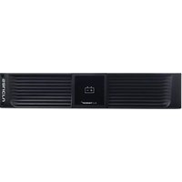
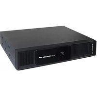
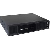
- SLC TWIN RT2
- 0,7.. 10 kVA
- General index
- INTRODUCTION.
- SAFETY INFORMATION.
- QUALITY ASSURANCE AND STANDARDS.
- PRESENTATION.
- INSTALLATION.
- OPERATION.
- CONTROL PANEL WITH LCD DISPLAY.
- MAINTENANCE, WARRANTY AND SERVICE.
- ANNEXES.
- THANK YOU LETTER.
- SALICRU
- USING THIS MANUAL.
- Compliance with the "Safety Instructions" is mandatory and the user is legally responsible for compliance and enforcement.
- Conventions and symbols used.
- STATEMENT BY THE MANAGEMENT.
- STANDARDS.
- WARNING!:
- First and second environment.
- First environment.
- Second environment.
- ENVIRONMENT.
- Recycling of the equipment at the end of its useful life:
- Packaging:
- Batteries:
- VIEWS.
- Views of the device.
- DEFINITION OF THE PRODUCT.
- Nomenclature.
- Note related to B0 and B1 batteries:
- OPERATING PRINCIPLE.
- UPS OPERATING MODES.
- Notable features.
- OPTIONAL EXTRAS.
- Isolation transformer:
- Exterior manual maintenance bypass.
- Communication card.
- Integration into computer networks using an SNMP adapter.
- Modbus RS485.
- Interface to relays.
- Extendable guide kits for mounting in a rack cabinet.
- RECEPTION OF THE DEVICE.
- Reception, unpacking and contents.
- Storage.
- Unpacking.
- Transport to the site.
- Siting, immobilising and considerations.
- Rotation of the control panel with LCD display.
- Vertical tower-type mounting.
- Vertical tower-type mounting with backup extension (battery module).
- Mounting as a rack in a 19" cabinet.
- Preliminary considerations before connection.
- Preliminary considerations before connection, regarding the batteries and their protections.
- Connection elements.
- CONNECTIONS.
- Connection of the input.
- Before working on the circuit.
- Connection to IEC connectors or output terminals.
- Connection of loads in models up to 3 kVA.
- Connection of loads in 4 to 10 kVA 10 kVA.
- Connection to external batteries (backup extension).
- Two devices must not be connected to the same battery module.
- Connection of the input earth terminal (⊥) and the earth connection terminal (⊥)
- Terminals for EPO (emergency power off).
- Terminals for digital input and output to relay. Only in models with power ratings > 3 kVA.
- Manual bypass auxiliary contact terminals. Only in models with power ratings > 3 kVA.
- Connection in parallel, only in models with power ratings > 3 kVA.
- Introduction in redundancy.
- Installation and operation in parallel.
- Communication port.
- RS232 and USB port.
- Smart slot for the integration of an electronic communication unit.
- Installation.
- Protection against voltage spikes for the modem / ADSL / fax, etc., line.
- Software.
- • Download of free ViewPower software.
- • Installation procedure:
- Considerations before start-up with connected loads.
- START-UP.
- Checks before start-up.
- UPS START-UP AND SHUTDOWN.
- UPS start-up with mains voltage.
- UPS start-up without mains voltage.
- UPS shutdown with mains voltage.
- UPS shutdown without mains voltage.
- OPERATING PROCEDURE FOR A PARALLEL SYSTEM (ONLY IN 4 TO 10 KVA MODELS).
- HOW TO ADD A UPS TO A SYSTEM IN PARALLEL OPERATION OR TO A FUNCTIONING SINGLE UPS (ONLY IN 4 TO 10 KVA MODELS).
- HOW TO REPLACE A FAULTY UPS IN AN OPERATIONAL PARALLEL SYSTEM.
- GENERAL INFORMATION FOR THE SERIES.
- Information represented by the display.
- Common messages shown on the LCD display.
- CONTROL PANEL FOR MODELS UP TO 3 KVA.
- Composition of the control panel with LCD display.
- Audible alarms.
- Location of the adjustment parameters on the display.
- Settings.
- Ah configuration of parameter '12'.
- Operating mode / Description of state.
- CONTROL PANEL FOR 4 KVA TO 10 KVA MODELS.
- Audible alarms.
- Optical indications.
- Location of the adjustment parameters on the display.
- Settings.
- Operating mode / Description of state.
- Operating mode / Description of state.
- BATTERY MAINTENANCE.
- Notes for the installation and replacement of the battery.
- UPS TROUBLESHOOTING GUIDE.
- Troubleshooting guide for devices up to 3 kVA.
- Troubleshooting guide for 4 kVA to 10kVA devices.
- WARRANTY CONDITIONS.
- Terms of the warranty.
- Exclusions.
- TECHNICAL SERVICES NETWORK.
- GLOSSARY.
Brand : Salicru
Model : SLC TWIN RT2
Category : Inverter