
NV-777 - VCR PANASONIC - Free user manual and instructions
Find the device manual for free NV-777 PANASONIC in PDF.
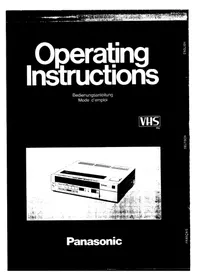


| Product Type | VHS Video Cassette Player/Recorder |
| Brand | Panasonic |
| Model | NV-777 |
| Video System | PAL, 625 lines, 50 fields |
| Recording/Playback Time | Up to 240 minutes with NV-E240 tape |
| Tape Format | VHS, 12.7 mm width, high density |
| Tape Speed | 23.39 mm/s |
| Inputs | Video IN (BNC), Audio IN (RCA), Microphone IN (6.3 mm), Camera Remote |
| Outputs | Video OUT (BNC), Audio OUT (RCA), RF Modulated (UHF channel 36, 75 ohm) |
| Audio | Monaural with Dolby Noise Reduction, Frequency response 80 Hz - 10 kHz |
| Power Supply | 220-240 V AC, 50-60 Hz |
| Power Consumption | Approx. 38 W |
| Dimensions (W x H x D) | 430 x 115 x 372 mm |
| Weight | 10.4 kg |
| Timer Programming | 14-day, 4 programmes; includes daily recording option |
| Special Playback Modes | Super Still, Super Fine Slow, Cue/Review, Still Advance, Reverse Play, Variable Slow |
| One-Touch Timer Recording (OTR) | 30/60/90/120 minutes selectable |
| Insert Editing | Allows inserting new video onto pre-recorded tape |
| Noise Reduction | Dolby NR (switchable) |
| Remote Control | Infrared with full function control including multi-motion playback |
| Maintenance | Wipe with dry cloth; do not use chemicals; avoid dew formation |
| Safety Features | Dew indicator; auto stop after 5 min in pause/slow; protection against magnet and moisture |
| Accessories Included | DIN-DIN coaxial cable, Infrared remote controller |
| Reparability / Spare Parts | No user-serviceable parts; refer to qualified service personnel |
Frequently Asked Questions - NV-777 PANASONIC
User questions about NV-777 PANASONIC
0 question about this device. Answer the ones you know or ask your own.
Ask a new question about this device
Download the instructions for your VCR in PDF format for free! Find your manual NV-777 - PANASONIC and take your electronic device back in hand. On this page are published all the documents necessary for the use of your device. NV-777 by PANASONIC.
USER MANUAL NV-777 PANASONIC
Operating Instructions
Operating Instructions
Operating Instructions

PAL

Panasonic
TABLE OF CONTENTS
Page
2 FOR YOUR SAFETY 3 FEATURES 4 ABOUT THE CASSETTE 5 CONTROLS AND COMPONENTS 8 INSTALLATION 9 ADJUSTING TV TO THE RF OUTPUT CHANNEL OF VTR 10 VTR TUNER SETTING 11 CLOCK TIME ADJUSTMENT 12 BASIC OPERATION 14 RECORDING OF TV PROGRAMMES 15 PLAYBACK 17 INFRA-RED REMOTE CONTROL 19 PROGRAMMING THE TIMER FOR TIMER RECORDING 22 AFTER PROGRAMMING A TIMER RECORDING OR CHECKING PROGRAMMES 23 ONE-TOUCH TIMER RECORDING (OTR) 25 INSERT EDITING (Insert Recording) 27 CAMERA RECORDING 28 AUDIO DUBBING 29 DUBBING 30 PRECAUTIONS 32 DEW CONDENSATION 33 BEFORE REQUESTING SERVICE 34 SPECIFICATIONS
IMPORTANT
"Unauthorized recording of copyrighted television programmes, films, video tapes and other materials may infringe on the rights of copyright owners and be contrary to copyright laws."
WARNING
TO PREVENT FIRE OR SHOCK HAZARD, DO NOT EXPOSE THIS EQUIPMENT TO RAIN OR MOISTURE.
REMARKS (NV-777 West Germany model only)
This set can be used for special recording/playback of SECAM colour signal.
SECAM tapes which have been recorded on specified SECAM-VHS recorder can be played back in Black-White on this set.
This apparatus was produced to BS 800:1977.
FOR YOUR SAFETY
■ DO NOT REMOVE PANEL COVER BY UNSCREWING.
To prevent electric shock, do not remove cover. No user serviceable parts inside. Refer servicing to qualified service personnel.
■ AC POWER CORD CONNECTION NV-777-B only.
The wires in the mains lead of this apparatus are coloured in accordance with the following code.

As the colours of the wires in the mains lead may not correspond with the coloured markings identifying the terminals in your plug proceed as follows:
The wire which is coloured BLUE must be connected to the terminal which is marked with the letter N or coloured black. The wire which is coloured BROWN must be connected to the terminal which is marked with the letter L or coloured red.
FEATURES
4 hours recording and playback
The unit can record and play back up to 4 hours on the VHS format in an excellent picture quality when used NV-E240 tape.
Super still, Super fine slow
For clearer, less blurred still picture and slow motion.
Multi-motion playback
In addition to regular playback, Super still and Super slow, you can operate multi-motion playback as follows: CUE (forward at 9 times normal speed), REVIEW (at 9 times normal speed in reverse), STILL ADVANCE (to advance a still picture), VARIABLE SLOW (at 1/5–1/30 normal speed), REVERSE PLAY (at normal speed in reverse).
Front loading system
This new design enables you to insert a video cassette in front without taking up space. The Cassette-In Indicator "OTO" appears when the video cassette is in the VTR.
Infra-red remote control
The remote control allows the following VTR functions.
●VTR ON/OFF ●RECORD ●PLAY ●CUE ●REVIEW ●PAUSE/STILL ●STILL ADVANCE ●VARIABLE SLOW ●FAST FORWARD ●REWIND ●CHANNEL CHANGE ●STOP
One-Touch Timer Record Button
One-Touch Timer Record (OTR) Button enables you to do impromptu timer recordings at any time. Just select the channel to be recorded and push the OTR Button for 30, 60, 90, or 120 minutes of recording.
Insert Editing
The Insert Editing allows you to insert new pictures onto a pre-recorded tape. To complete tape editing you can add the sound with the audio dubbing function.
14-day 4 programmable timer
The built-in timer allows you to record TV programmes up to two weeks ahead. 4 different programmes can be recorded (including "Everyday" Recording).
Recording one programme while watching another
The built-in tuner allows you to record a programme that you don't want to miss while watching another programme.
Remaining Tape Indicator
During recording and regular playback, the remaining tape time is indicated on the Electronic Counter.
Fine Editing Function
When the Pause/Still Button is pressed during recording, the tape will automatically rewind slightly to reduce noise.
Dolby Noise-Reduction System*
This VTR can be operated with Dolby NR. Dolby NR is a noise reduction system.
"Dolby" and the double-D symbol are trademarks of Dolby Laboratories Licensing Corporation.
Auto rewind (except timer recording)
When the tape reaches its end, the tape will automatically rewind to this beginning or to the "0000" counter position if the Memory Switch is ON.
ABOUT THE CASSETTE

Insert the video cassette with the window side up, the arrow pointing away from you and slide the cassette into the VTR until the mechanism draws it in automatically.
- The cassette can be loaded only when the VTR is powered ON. Do not force the cassette into the cassette holder with the power off.
Types of Video Cassette
Use types of video cassette with the VHS mark in this VTR.
NV-E240: for 240 minutes of recording and playback
NV-E180: for 180 minutes of recording and playback
NV-E120: for 120 minutes of recording and playback
NV-E90: for 90 minutes of recording and playback
NV-E60: for 60 minutes of recording and playback
NV-E30: for 30 minutes of recording and playback
CONTROLS AND COMPONENTS
TOP and FRONT
① Eject Button
For ejecting the cassette.
② VTR ON/OFF Switch
With indicator lamp for turning the VTR on and off.
③ Camera Input Indicator Lamp
Lights up when the Input Signal Selector is set to "CAMERA".
4 Rewind/Review Button
Press this button to rewind tapes. During the play mode pressing this button will allow you to view the picture in reverse at about 9 times the recorded tape speed.
⑤ Stop Button
For stopping the tape.
⑥ Play Button
With indicator lamp for playback.
7 Fast Forward/Cue ▶▶ Button
Press this button to move the tape forward rapidly. During the play mode pressing this button will allow you to view the picture in the forward direction at about 9 times the recorded tape speed.
8 Record Button
With indicator lamp for recording. Press this button together with PLAY button.
9 Pause/Still Button
With indicator lamp for a temporary halt of recording and for obtaining still-picture playback.
10 Cassette Holder
For insertion of a video cassette.

⑪ Reverse Play Button
For playback at normal speed in reverse.
12 Slow Button
⑬ Tape Select Switch
Set this switch to the "~E180" position. When using NV-E240 video cassette, set this switch to "E240" so that the Remaining Tape Time Readout can function properly.
14 Slow-motion Slide Controller
For controlling slow-motion from 1/30 to 1/5 speed with the Slow Button depressed.
15 Audio Dub Button
With indicator lamp for Audio Dubbing.
16 Still Advance Button
For advancing a still-picture frame by frame with the Pause/Still Button depressed.
17 Electronic Counter

When the dew forms:

18 Reset Button
For setting the counter to "0000".
19 Memory ON/OFF Switch
For automatic tape stop when the counter reaches "0000" in the rewind mode. "M" is indicated on the Electronic Counter when the Memory Switch is ON.
20 Dolby NR Switch
With indicator lamp for turning on and off the noise reduction system Dolby NR during recording and playback.
21 One-Touch Timer Rec (OTR) Button See page 23.
22 Time Display
Indicates either the time and day or recording start/stop times for the timer recording.
23 Channel Indicator/Up and Down Buttons
24 Timer Controls
See pages 11 and 19–21.
25 Tuner Set-up Controls See page 10.
26 Infra-red Remote Control Receiver
Receives the signal from the infra-red Remote Control.
27 Dim/Bright Switch
Changes the brightness of the time display.
28 Timer Record Switch
For turning the VTR on or off for timer recording.
29 Audio Input Socket
For connecting an audio cable of a video camera, a component audio system or another VTR.
30 Camera Remote Control Socket
For connecting a remote control cable of a video camera (optional).
31 Video Input Socket
For connecting a video cable of a video camera or an output video signal of another VTR.
32 Microphone Input Socket
For connecting a microphone.
33 Picture Sharpness Control
For making the picture's outline sharper or softer. It has no effect when recording.
34 Tracking Control
Use this control during playback if the image is partially obscured by bands of noise.
35 Input Signal Selector
For selecting the input signal to be recorded.
CAMERA: To make a recording using a video camera which is connected to the Video Input Jack and the Audio Input Jack.
TUNER: To record a TV programme with the built-in tuner of the VTR.
36 Slow Tracking Control
To reduce noise during Slow and Still playback modes.
REAR

37 Video Output Socket
For connecting a video cable to a TV monitor etc.
38 Audio Output Socket
For connecting an audio cable of a TV monitor, a component audio system, or another VTR.
39 Colour Mode/Test Signal Switch
This switch has the following two functions:
(1) to tune the TV to the RF output channel and (2) to stabilize the colour image during recording or playback. Normally, the switch should be set to the "AUTO" position.
To tune the television to the RF output channel:
Set this switch to "TEST" to turn the TV channel to VTR RF Output.
To stabilize the colour image:
Set this switch to "COLOUR" to make a stable colour recording where the supplied corrent is extremely low. For playback, this switch must be in "COLOUR".
40 RF Converter Channel Selector
41 AC Mains Cord
42 RF Signal Level Switch
Used to attenuate the reception of the VHF and/or UHF antenna signals.
If the reception is normal, set to "HIGH". If the signal is strong (the stripped pattern appears at the top of the picture on TV), set to "LOW".
43 VTR RF Output Terminal
For connection to the antenna terminal (COAXIAL type) of TV with the DIN-DIN Coaxial Cable supplied with the unit.
44 RF Input Terminal
For connection with the external aerial.

① Connect the external aerial to the RF Input Connector. ② Connect your TV to the VTR RF Output Connector with the supplied DIN-DIN Coaxial Cable. ③ Plug into the mains. ● Refer to "PRECAUTIONS" page 30 before installation.
ADJUSTING TV TO THE RF OUTPUT CHANNEL OF VTR


① Turn TV on and select a spare channel that will be used for playback, in some cases this may be marked A/V. ② Turn the VTR on. ③ Set Colour Mode/Test Signal Switch to "TEST" position and tune the TV until the pattern shown below is received.

④ Set Colour Mode/Test Signal Switch to "AUTO".
Your TV is now ready to receive the RF output signal from the VTR.
Note:
When Colour Mode/Test Signal Switch is in "TEST", the black and white pattern will be seen on TV. When it is in "AUTO", you can use the VTR normally. If, during recording or playback, the colour is not satisfactory, it can be stabilized by setting this switch to "COLOUR".
VTR TUNER SETTING
| VHF | UHF | ||
| I | III | U | |
| NV-777-B | — | — | 21-69 |
| NV-777-E, EG | Band I 2-4 | Band III 5-12 | Band IV/V 21-69 |
| NV-777-EO | E2-S3 | M1-U9 | 21-69 |
① Turn on the VTR. Select VTR RF Output.

① Turn TV ON and select the pretuned VTR RF output channel. ② Turn the VTR ON. ③ Select Input Signal Selector to "TUNER". ④ Set the PRESET Switch to the "PRESET" position.

5 Press Channel Up or Down Button to select your desired channel.

⑥ Set Band Switch to be matched "I", "III" or "U" position. ●For model NV-777-B, this step is not necessary. (There is no switch.)

7 Turn the tuning control until the picture on your TV is satisfactory.

A white indicator in the window shows the approximate position of the tuning range. It moves right for high and left for low channel range.
8 Press the Memory Button after the adjustment for the channel is completed (the corresponding lamp lights up). AFC Indicator appears on the Channel Indicator.

⑨ Repeat steps ⑤~⑧ for each channel you desire to tune. ⑩ Set the PRESET Switch to the "NORMAL" position.

If you need Fine Tuning (This function does not come with NV-777-B.)
① Set PRESET Switch to "NORMAL". ② Press Tuning Up or Down Button.
To return the channel to its former state, press the MEMORY/AFC Button.

CLOCK TIME ADJUSTMENT
The clock is based on a 24 hour cycle.
When the Power Switch of the unit is turned on for the first time or if there is a power failure for more than 3 days, the digit clock display flashes "SUN 0:00" to warn that the Timer has lost the preset time memory.

For example set the clock for "SUN 10:15"
1 Set MODE SELECTOR Switch to "CLOCK".
② Press DAY, HOUR, MIN Buttons (+ or -) to set the clock.
- For example, if the present time is 10:14 on Sunday, first set the clock for "SUN 10:15".
③ When the time becomes 10:15, set MODE SELECTOR Switch to "NORMAL". - The clock will start on 00 seconds.
(The seconds, however, are not displayed).
- The battery back-up system retains the present time memory for about 3 days in case of a power failure after plugging the VTR into uninterrupted for two days.
Dim/Bright Switch
BASIC OPERATION


To prepare for recording and playback
① Press VTR ON/OFF Switch ON. ② Make sure if Timer Record Switch is OFF. ③ Reset COUNTER to "0000" by pressing RESET Button. ④ Set INPUT SIGNAL Selector to "TUNER". ⑤ Push in the video cassette into the Holder until it is pulled inside by VTR.
●The cassette can be loaded only when the VTR is powered. Do not force the cassette into the cassette holder with the power off.
- When the cassette is loaded, the Cassette-In Indicator " [O] " is displayed on the Electronic Counter.
6 Turn TV on and select the VTR RF output channel.
Input Signal Selector
To select recording source.
TUNER: For regular TV recording.
CAMERA: Camera Recording. Audio Dubbing. Dubbing.
Tape Select Switch
For working the Remaining Tape Time Readout properly, set this switch.
"~E180"—for NV-E30, 60, 90, 120, 180.
"E240"—for NV-E240.
After finishing recording or playback:
- Press EJECT Button, remove VIDEO CASSETTE.
- Make a habit of fully rewinding the tape by pressing the REWIND Button before "Eject". This will prevent the tape damage.
- Turn VTR and TV OFF.
To watch TV programme
① Turn VTR OFF. ② Select a desired channel on TV.
Don't remove the AC power cord from the mains to watch TV programmes.
Basic Functions
Dolby Noise Reduction System

Dolby NR is a special noise reduction circuit which reduces tape hiss noise.
- If a cassette has been recorded with the Dolby NR it should be played back with the Dolby NR Switch is ON.
Memory ON/OFF Switch

To find the beginning of the recorded portion easily, set the Memory ON/OFF Switch to ON. During Rewind or Fast Forward, the tape will stop at the portion of the Tape Counter "0000" automatically.
Picture Sharpness Control

You can set the picture image to either sharp and detailed or soft and subtle to suit your taste.
Remaining Tape Time

During recording and playback, the remaining tape time is indicated at 5-minute intervals on the Electronic Counter. When you start a recording or a playback, the "[" indicator appears for several seconds on the Counter, which means the remaining tape time is counted. The remaining tape readout will flash on and off when there are less than 5 minutes of tape remaining.
- Remaining Tape Time Readout is cancelled if Fast Forward, Rewind, Cue/Review, or Reverse playback are performed. - Remaining Tape Time Readout is an approximate estimate.
Tape Select Switch

The Remaining Tape Time Readout does not function with tapes not made for this type of VTR or tapes wound to non-standard length (e.g., NV-E240). When you use the E240 video cassette tape, set this switch to the "E240" position in order to function the Remaining Tape Time Readout properly. - Set this switch to the "~E180" position when using NV-E30, 60, 90, 120, 180 video cassette tapes.
RECORDING OF TV PROGRAMMES
Prepare for recording as follows:
- Turn the VTR ON. ●Make sure that the Timer Record Switch is OFF.
- Reset the Counter to "0000".
- Set Input Signal Selector to "TUNER".
- Insert a cassette. Make sure that the tab is in place.
- Set the Tape Select Switch to "~E180" or "E240" according to types of the tapes.
- Turn TV ON and select channel for VTR RF Output.
① Select CHANNEL to be recorded and confirm proper reception on the TV.

2 Press RECORD Button and PLAY Button at the same time.

- Your TV does not have to be on to make a recording because the VTR will record a TV programme without the aid of your TV. Its use is only for monitoring. -CH LOCK Indicator appears on the Channel Indicator.
If you wish to avoid recording unwanted material
3 Press PAUSE/ STILL Button to stop the tape temporarily.

●Always use PAUSE Button to obtain proper recording continuity, but don't pause for more than 5 minutes. If the pause mode continues for more than 5 minutes, the VTR will be automatically stop to protect the tape and the video heads. ●To obtain proper continuity from the stop mode:
- Play back the last part of the pre-recorded material to confirm its ending point, and then press PAUSE Button.
- Press RECORD Button and PLAY Button at the same time. (The VTR is still in the pause mode.)
- Press PAUSE Button to start recording.
After finishing recording
4 Press STOP Button.

RECORDING ONE TV PROGRAMME WHILE WATCHING ANOTHER
You can watch one channel on TV while recording another by VTR.
PLAYBACK
Prepare for playback as follows:
●Turn the VTR ON. ●Make sure that the Timer Record Switch is OFF. - Reset the Counter to "0000". - Set the Input Signal Selector to "TUNER". - Insert a cassette. - Set the Tape Select Switch to "~E180" or "E240" according to types of the tapes. - Turn TV ON and select channel for VTR RF Output.
① Press PLAY Button.

- Adjust Tracking Control on the VTR or fine tune your TV if necessary.
- Set the Dolby NR Switch for the same position that the tape was recorded. ●Control the picture as you like with the Picture Sharpness Control. (sharp or soft)
(No audio is reproduced.)
SUPER STILL playback
2 While playback mode, press PAUSE/STILL Button to view a still-picture.

- If you should leave the unit in pause for more than 5 minutes, the unit will stop automatically to protect the tape and the video heads.
STILL ADVANCE playback
3 During pause mode, press STILL ADVANCE Button. Each time you press this button, the still-picture will advance one single field.

CUE playback
4 When CUE Button is held down during playback, pictures at 9 times normal speed will be played.

- Noise which takes the form of horizontal bars appears on the TV during CUE/REVIEW. This is not an indication of trouble.
- Also, the top of the picture may become distorted during CUE/REVIEW. This is not an indication of trouble.
- When the picture slips vertically during CUE/REVIEW, adjust the TV set's vertical hold control. •CUE/REVIEW playback can be operated even during Super Still or Super Slow playback.
REVIEW playback
⑤ When the REVIEW Button is held down during playback, pictures at 9 times normal speed will be played in reverse.

SUPER FINE SLOW playback
⑥ When the SLOW Button is pressed during normal playback, slow-motion pictures at 1/5–1/30 normal speed can be obtained with the Slow-motion Slide Controller.

- If Super Slow playback continues for more than 10 minutes, it is automatically stopped.
If noise appears during Super Still, Still Advance or Super Slow playback, first set the VTR to the slow-motion playback mode and adjust the Slow Tracking Control.
- This noise may still remain even if the Slow Tracking Control is adjusted, if you play back the tape which recorded on other VTR.
REVERSE playback
⑦ When the REV PLAY Button is pressed during playback, pictures in reverse at normal speed can be obtained.

- When reverse playback continues for more than about 10 minutes, the function is automatically released and the unit is set to the stop mode.
After finishing playback
8 Press STOP Button to stop playback.

- While playing back a tape in the Super Still or Super Slow mode on a TV set equipped with an automatic vertical hold, the picture may shake vertically. In this case, set the TV set's vertical hold AUTO/MANUAL selector to the MANUAL position, and adjust vertical hold.
INFRA-RED REMOTE CONTROL


- The remote sensor light sensing angle is about 60 degrees. - The unit should be used within a range of about 7 meters from the front of the VTF.
Bouncing wave may reach the sensor, but transient waves directly to sensor for best results.
① ON INDICATOR:
For indicating remote control operations.
② VTR ON/OFF:
For turning the VTR on and off.
③ REMOTE CONTROL SWITCH:
Set this switch to ON when using the unit.
④ CH UP Button:
For advancing to the next channel.
⑤ CHANNEL SELECTION BUTTONS:
⑥ RECORD (Two Buttons Entry):
To start recording, press the two buttons simultaneously.
⑦ REWIND
⑧ PLAY
9 FF
10 STOP
11 PAUSE/STILL
12 STILL ADV
13 SLOW, "+", "-":
Press the SLOW button for field-slow at 1/15 of normal speed. Speed can be varied from 1/5 to 1/30 of normal speed by using the "+" and "-" buttons.
Note:
- If you leave Super-Slow mode for more than 10 minutes, the VTR will stop automatically to protect the tape and the video heads.
- Adjust the Slow Tracking Control if necessary.
14 REVIEW, CUE
Note:
Infra-red beam will bounce off the walls and eventually reach the remote sensor, but for best results transmit the beam directly to the remote sensor.
Sunlight may interfere with the beam.
Power Source of Wireless Remote Control
The Wireless Remote Control is powered by two "AA" size batteries. The life of the batteries is about a year, although it depends on the number of times the unit is used. Replace or inspect the batteries once a year.
BATTERY REPLACEMENT CAUTION
- Load the new batteries with their polarities (⊕ and ⊖) aligned properly.
- Do not heat, disassemble or short-circuit the old batteries.
- If you do not intend to use the remote control for a long period of time, remove the batteries and store them in a cool, dry place.
- Remove spent batteries immediately and dispose of them.
- Do not mix old and new batteries. (Also never mix alkaline batteries with manganese batteries.)
Load the batteries as follows:


① Remove the Battery Compartment lid. ② Place two batteries in the Battery Compartment as indicated inside the Battery Compartment. ③ Replace the lid.
Direct Access of the Multi-motion playback
The VTR and the Infra-red Remote Controller allow you to operate directly any multi-motion playback during playback.
![graph TD A["Super Still Mode"] --> B["Press and hold Cue Button"] A --> C["Press and hold Rev Button"] A --> D["Press REV PLAY Button"] A --> E["Press and hold Cue Button"] A --> F["Press REV PLAY Button"] A --> G["Press PAUSE/STILL Button"] H["Super Slow Mode"] --> I["Cue Playback"] H --> J["Review…](/content/2026/05/1006388/images/7f643968df5cbce2494a9081a3a47431180550ad725c5c3f31366884b4396641.jpg)
*NOTE:
When you press the SLOW Button on the VTR, you can control the slow-motion speed (1/5–1/30) by the Slow-motion Slide Controller on the VTR. Pressing the SLOW Button on the Infra-red Remote Control you can control the slow-motion speed by the “+” and the “-” Buttons on the Infra-red Remote Control. (Then, the Slow-motion Slide Controller is not operative.)
PROGRAMMING THE TIMER FOR TIMER RECORDING
The timer can be programmed for unattended recording of up to 4 programmes a maximum of two weeks in advance. It can also be programmed to record automatically the same programme every day (e.g. the noon news broadcast) until the cassette is full. For timer recording, the following data have to be input: ① the number of the programme (1-4), ② the day, when the recording is to be made, ③ the start time of the recording, ④ the stop time of the recording, and ⑤ the TV channel to record from.
Example: The present time is Monday, 11:30 AM, and you want to programme the timer as follows: ① programme number, ② Tuesday (tomorrow), ③ the TV programme starts at 8:00 PM, and ④ it ends at 9:00 PM and, ⑤ it is broadcast on TV channel 3.
Before starting the programming, make sure that:
—the clock shows the present time correctly; —the VTR ON/OFF Switch is ON; —the Timer Record Switch is OFF.
① Set the Mode Selector to PROGRAMME. (To find out which programme numbers are not occupied.)

- The DAY, HOUR and MIN indications will disappear, and the programme number indications 1, 2, 3, 4 will flash.
- The number indications of previously set, but not yet recorded programmes will appear without flashing.
② Press the PROGRAMME Button. (to select the programme number to be programmed.)

- One second after the programme number has been selected, the "ON" indication will start to flash.
③ Press the ON Button.

CH" Indication
- The "ON" indication will remain displayed.
- The symbol “I” means the first week, “II” means the second week.
- The "CH" indication will flash to show that the TV channel can now be selected.
4 Press the Channel UP or Channel Down Buttons to select the desired channel.

5 Press the "+" or "-" Buttons for DAY, HOUR and MIN. (to set the day and start time of the TV programme to be recorded.)

- The "ON" indication appears to show that the start time can now be programmed. About 4 seconds after releasing the MIN Button, the "OFF" indication starts to flash, however, it is still possible to change the day and time setting.
- If you don't press the MIN Button during the setting of the start time, the "OFF" indication will not flash, but the OFF Button can be operated.
- For "Everyday" Recording, push the DAY "+" Button repeatedly until the indications for all days of the week are on, or push the DAY "-" Button once.
- The "Everyday" Recording will continue until the cassette is full.
6 Push the OFF Button, and then press the "+" or "-" Buttons for DAY, HOUR and MIN. (to set the day and stop time of the TV programme to be recorded.)

- To preset the next programme (number 1 in the example), push the PROGRAMME Button once to advance to the next programme number, and repeat steps 2-6.
7 After finishing the programming, return the Mode Selector to NORMAL.

- Even if the VTR ON/OFF Switch is turned off, the programmed start and stop times for Timer Recording will be retained.
- The flashing channel indication (the number of the TV channel selected in the programme for Timer Recording) will disappear.
8 Set the Timer Record Switch to ON. (if you don't want to check the Timer Recording programme.)
●This switches the VTR over to the stand-by condition and it will function as you have programmed it to.
Checking a Timer Recording Programme
Check that: ●the Mode Selector is set to NORMAL; ●the VTR ON/OFF Switch is ON.
① Set the Timer Record Switch to OFF. ② Press the PROGRAMME Button to select the number of the programme you want to check.

③ Set the Timer Record Switch to ON again.
- During the checking of a timer programme, the programmed channel number will flash.
- If the broadcasting time of one programmed TV programme overlaps that of another, the programme number of the overlapped programme will flash.
- If the PROGRAMME Button is pressed again within 6 seconds, the next timer programme can be checked.
Cancelling a Timer Recording Programme
Check that: ● the VTR ON/OFF Switch is ON; ● the Timer Record Switch is OFF.
① Switch the Mode Selector to "PROGRAMME".

② Press the PROGRAMME Button repeatedly until the number of the programme that you want to cancel is displayed.

③ Press the ON Button.
The present time will be displayed, and the recording start and stop times of the selected programme are cancelled.

④ Return the Mode Selector to "NORMAL".

AFTER PROGRAMMING A TIMER RECORDING OR CHECKING PROGRAMMES
① Set the Timer Record Switch to ON.

- When the Timer Record Switch is set to ON, the Timer Record Mark "☐" will be displayed, the VTR is set to the stand-by condition, and only the timer is left operating.
- If the erasure prevention tab of the cassette is missing, the Timer Record Mark "☐" will flash to warn you that the timer recording cannot be made.
② The timer will automatically function and cause the VTR to record as you have programmed it to. The TV programmes will be recorded in chronological order, regardless of the programme number.
③ After all programmed Timer Recordings have been made, set the Timer Record Switch to OFF.
(As long as the Timer Record Switch is ON, no other functions can be operated.)
- This VTR has a built-in battery power back-up system to protect the programming in the timer as well as the functioning of the clock for up to 3 days in case of a power failure. However, it takes two days to fully charge the back-up circuit, after the VTR has been connected to the mains.
- If the power is interrupted for more than 3 days, the timer recording(s) will not be performed, or not continued in case of "Everyday" recording.
- If a power failure occurs during a timer recording, the recording will be interrupted until the power supply is restored.
- The "Everyday" recording will continue over the full length of a cassette for as long as the Timer Record Switch is ON.
① Select the TV channel to be recorded. ② Press the OTR Button repeatedly (as shown in the table below) to select the desired recording duration.
| OTR Button | Timer Indication (OTR Time) |
| 1st push | 0:00 (standby) |
| 2nd push | 0:30 |
| 3rd push | 1:00 |
| 4th push | 1:30 |
| 5th push | 2:00 |
| 6th push (=1st push) | 0:00 |
●The "OTR" Indication and "CH LOCK" Indication will be displayed. - The Timer Display Readout will change from the present time to "0:00". ●Each time the OTR Button is pressed, the Timer Display Readout will change as shown in the table on the left. - The Timer Display Readout shows the recording duration. During recording, it will count down and show the remaining time until "0:01". When the recording ends, the Timer Display will again show the present time. - If you want to stop the One-Touch Timer Recording, press the VTR ON/OFF switch to OFF or press the OTR Button again so that the Timer Display will again show "0:00". 8 seconds later, the Timer Display will again show the present time and the recording will then stop.
③ The VTR is automatically switched off, when the completed. To turn the VTR on again, press the ON/OFF Switch to the "ON" position.
Example of a One-Touch Timer Recording![graph TD A["To stop OTR during a recording."] --> B["1 push 0:30"] B --> C["push repeatedly"] C --> D["8 seconds later"] D --> E["The OTR will stop"] E --> F["1 minute later OTR will stop 11:32. (The present time will be shown again)."] F --> G["3 pushes 1:00"] G --> H["35 minutes later 0:25"] H -->…](/content/2026/05/1006388/images/4913dc0440cc33070f32e63f82f9e41595663b26430bd9087bc468ac04776107.jpg)
Caution:
- If a One-Touch Timer Recording overlaps a programmed Timer Recording, the One-Touch Timer Recording will have priority.
- The recording time can be made longer by pushing the OTR Button during a One-Touch Timer Recording.
If you want to know the present time during a One-Touch Timer Recording
- Press the PROGRAMME Button. The present time will be shown on the Timer Display for 4 seconds.


INSERT EDITING (Insert Recording)
![graph TD A["Already recorded tape"] --> B["(Tape after insert editing)"] B --> C["PICNIC"]](/content/2026/05/1006388/images/e0402121eb6a1325df4bf626071684fc7f82ca16bf0bd3775b8a7b2b485d127a.jpg)

Insert Editing is a handy function for editing tapes by inserting new scenes from a camera or another video recorder into an already recorded video tape. You can put together your own edited programmes. In Insert Editing, only the new video signals are recorded, but the original sound remains on the tape. If you want to replace the original sound after the Insert Recording, follow the instructions given in "AUDIO DUBBING" on page 28.
VIDEO IN
For the connection between this video recorder and a second VTR or a video camera for Insert Editing, refer to "CAMERA RECORDING" on page 27 or "DUBBING" on page 29.
① Press the Play Button.

② Check the playback picture and use the Tracking Control, if necessary, to obtain perfect picture quality.

Adjust the Tracking Control as shown below, when inserting a new recording on a tape that was recorded on another video recorder.
- Rotate the Tracking Control slowly clockwise until a noise bar appears on the screen, and make a note that this is position A.

- Then rotate the Control slowly counterclockwise until another noise bar appears, and make a note that this is position B.

- Set the index mark of the Tracking Control to a point halfway between positions A and B.

Optimum tracking adjustment position
3 Find the exact point where the Insert Recording is to finish by using the Review, Cue or Slow Buttons.

4 Press the Reset Button at the point where the Insert Recording is to finish, to set the Tape Counter to "00" and set the Memory ON/OFF Switch to ON.

- Do not set the Memory ON/OFF Switch to OFF during Insert Recording.
- Ensure that the Tracking Control is adjusted properly before starting Insert Recording.
⑤ Press the Review, Cue, Play or Slow Buttons to find the point where the Insert Recording is to start.

6 Press the Pause/Still Button at the point where the Insert Recording is to start.

7 Press the Audio Dub Button together with the Record Button.
![graph TD A["Start"] --> B{Condition} B -->|Yes| C["Process Step 1"] B -->|No| D["Process Step 2"] C --> E["End"] D --> F["End"]](/content/2026/05/1006388/images/4d94beacfc06da602b7ed6f4e23a3b825a23d75fc5bb044cab34523e1b88cca2.jpg)
- The VTR uses the Audio Dub Button in the Insert Recording mode.
8 Start operating the camera or playback of the second video recorder, which you record from.
- During Insert Recording, pause operations cannot be performed using the camera's start/stop switch.
9 The Insert Recording will start as soon as the Pause/Still Button is pressed again.

10 The Insert Recording will finish at the point where the Tape Counter was reset to "0000", and the VTR will be switched over to the Still mode. However, you can press the Pause/Still Button to suspend the Insert Recording at any time, before this point is reached.
- If the inserted part is recorded from another VTR, the picture quality may be slightly inferior, as it is a second generation recording.
- The sound will not be recorded during Insert Recording, as explained in "AUDIO DUBBING" on page 28 and "CAMERA RECORDING" on page 27.
- The picture in the inserted part may be affected by some beat noise and colour blotching, but this is not an indication of trouble.


Prepare for camera recording as follows:
- Set Input Signal Selector to "CAMERA". Turn TV on and select the VTR RF output channel. Turn the VTR ON.
- Insert a cassette.
1 Turn the Camera AC Adaptor ON and make necessary adjustments on the camera. Refer to the operating instructions of the camera you are using.
2 Press RECORD Button together with PLAY Button, and the VTR will go into the standby mode.

4 Press STOP Button to stop recording •The antenna connection may remain connected using a camera.
③ Press the camera's start/stop switch to start recording.
To avoid recording unwanted material:
Depress the start/stop switch of the camera, and the tape will stop temporarily.
To resume recording, depress the camera's start/stop switch again. (To resume recording from the pause mode that is caused by the unit's pause button, release the pause button or depress the camera's start/stop switch twice.) However, if the pause mode continues for more than 5 minutes the VTR will release automatically and stop in order to protect the tape and the video heads.
AUDIO DUBBING
Note that the original soundtrack will be completely erased during audio dubbing.

Prepare for audio dubbing as follows:
- Set Input Signal Selector to "CAMERA".
- Turn the VTR on.
- Insert a cassette. Make sure that the tab is in place.
- Reset Tape Counter to "0000". ●Turn the TV on and select the VTR RF output channel.
1 Press PLAY Button to reach the point where you want to start audio dubbing.

② Press PAUSE/ STILL Button where you want to start Audio Dubbing.

③ Press AUDIO DUB Button together with PLAY Button.
![graph TD A["Block 1"] --> B["Block 2"] B --> C["Block 3"] C --> D["Block 4"] D --> E["Block 5"] E --> F["Block 6"] F --> G["Block 7"] G --> H["Block 8"] H --> I["Block 9"] I --> J["Block 10"] style A fill:#f9f,stroke:#333 style B fill:#f9f,stroke:#333 style C fill:#f9f,stroke:#333 style D fill:#f9f,…](/content/2026/05/1006388/images/5f75318bf1b85c4c63545c4ab3d04855375a96eeddc6b48e399456ed80b1a0c6.jpg)
4 Press PAUSE/STILL Button once again to release the tape from pause. Audio dubbing will start. 5 Press STOP Button to stop audio dubbing.
- When a microphone is used for dubbing, do not place it near the speaker of your TV while audio dubbing. A howling noise (feedback) may occur.
- If the cassette's tab is missing, no audio dubbing can be made.
DUBBING

Connect "VIDEO OUT" on the playback VTR to "VIDEO IN" on the recording VTR with a video cable.
- Video cable should be 75 ohm type (COAX) antenna cable for best results.
Connect "AUDIO OUT" on the playback VTR to "AUDIO IN" on the recording VTR with an audio cable.
● Audio cable can be ordinary audio shielded type.
1 Place the recorded cassette in the playback VTR and a blank cassette in the recording VTR. 2 Press PLAY Button on the playback VTR.

3 Press RECORD Button together with PLAY Button to set the recording VTR to dubbing.

4 Press STOP Button to stop the dubbing.

Re-recorded tape has poorer picture quality than the original.
PRECAUTIONS
Avoid sudden changes in temperature
If the VTR is suddenly moved from a cold place to a warm place, moisture may form on the tape and inside the VTR. In this case, the Dew Indicator will flash on and off and the VTR will not operate.

Humidity and dust
Avoid places where there is high humidity or dust, which may cause damage to internal parts.

Don't obstruct the ventilation holes
The ventilation holes prevent abnormal increase of temperature. Do not block or cover these holes. Especially avoid soft materials such as cloth or paper.

Keep away from high temperature
Keep the VTR away from extreme direct heat such as direct sunlight, heat radiators, or closed automobiles.

Keep magnets away
Never bring a magnet or magnetized object near the VTR because it will adversely affect the performance of the VTR.

No fingers or other objects inside
It is dangerous, and may cause damage to the VTR, to touch the internal parts of this VTR. Do not attempt to disassemble the VTR. There are no user serviceable parts inside.

Keep water away
Keep the VTR away from flower vases, tubs, sinks, etc. CAUTION: If liquids spilled into the VTR, serious damage could occur. If you spill any liquid into the VTR consult qualified service personnel.

Cleaning the VTR
Wipe the VTR with a clean, dry cloth. Never use cleaning fluid, or other chemicals. Do not spray any cleaner or wax directly on the VTR or do not use forced air to remove dust.

Stacking
Place the VTR in a horizontal position, and do not place anything heavy on it.

Video Head Clogging

Good Picture

Snowy Picture
The video heads are the means by which the recorder places pictures on the tape during recording, and reads pictures from the tape during playback. In the unlikely event that they become dirty enough to be clogged, no picture will be recorded or played back. This can easily be determined if, during playback of a known good tape, there is good sound, but no picture (or picture extremely snowy).
If this is the case, have the recorder checked by qualified service personnel.

Like dew, drops of moisture forming on the window pane of a heated room during winter, the same occurs on video recorder parts when:
—The VTR is in a room where the heater has just been turned on. —The VTR is in a room with steam or high humidity. —The VTR is brought from cold surroundings into a well-heated room. —When the VTR is suddenly brought from air-conditioned surroundings, such as a room or vehicle, to a place which is hot and humid.
When dew forms:
The Dew Indicator " ∅" will flash on and off on the Electronic Tape Counter and all the function buttons except the EJECT Button are made non-operational to protect the tape and the video heads.
When the Dew Indicator appears:
Take out the video cassette and leave the VTR ON and let it remain at room temperature until this indicator goes off. Although it depends on the surrounding conditions, the indicator will go off in several hours at most.
BEFORE REQUESTING SERVICE
No power...
- Check if the power plug is reliably connected to mains. ●Make sure that TIMER RECORD Switch is OFF.
The video cassette can't be inserted...
- Insert the cassette with the window side up and the safety tab facing you.
- Check if the VTR ON/OFF Switch is ON.
No operation starts when operation buttons are pressed...
- Check the Dew Indicator. If it is on, refer to page 32. ●Make sure that the TIMER RECORD Switch is OFF.
TV programmes can't be recorded...
- Check the connection of the VTR and TV. ●Make sure that the receiving channel of the VTR is properly tuned.
- Make sure that the erasure prevention tab of the cassette is not missing.
- Set Input Signal Selector to "TUNER".
Timer recording can't be performed...
- Set the recording start/stop time correctly. ●Make sure that VTR ON/OFF and TIMER RECORD Switches are ON.
- If there is a power interruption for more than 3 days before or during timer recording, the timer will lose its preset time memory and timer recording will not be performed.
There is no playback picture...
●Tune your TV to the VTR RF output channel. The playback picture is noisy or contains streaks... - Adjust by slowly turning Tracking Control.
If the top of your playback picture waves back and forth excessively...
- Adjust the horizontal hold control on your TV. Turn it slowly to correct for the wavy picture.
NV-777-EG, -B, -E, -EO
Power Source:
NV-777-EG, -E, -EO: 220 V AC 50-60 Hz
NV-777-B: 240 V AC 50-60 Hz
Power Consumption:
Approx. 38 watts
Video Recording System:
2 rotary heads, helical scanning system
Tape Speed:
23.39 mm/sec.
Tape Format:
Tape width 12.7 mm high density tape
Record/Playback Time:
240 min. with NV-E240
FF/REW Time:
Less than 5.5 min. with NV-E180
VIDEO
Television System:
CCIR: 625 lines, 50 fields, PAL colour signal
Modulation System:
Luminance: FM azimuth recording
Colour signal: converted subcarrier phase shift recording
Input Level:
VIDEO IN (BNC): 1.0 Vp-p,
Output Level:
VIDEO OUT (BNC); 1.0 Vp-p,
RF Modulated: UHF channel 36 (±4),
75 ohm, unbalanced
75 ohm, unbalanced
75 ohm, unbalanced
AUDIO
Input Level:
MIC IN jack (M6); -70 dB, Input Imp.,
LINE IN jack (RCA); -20 dB,
3.9 kohm, unbalanced
50 kohm, unbalanced
Output Level:
LINE OUT jack (RCA); -6 dB, Output Imp.,
1 kohm, unbalanced
Audio Track:
Video Horizontal Resolution:
1 track
Signal-to-Noise Ratio:
Colour: more than 240 lines
Video: more than 43 dB
Audio: more than 50 dB (Dolby NR IN)
Audio Frequency Response:
80 Hz-10 kHz
Operating Temperature:
5°C-40°C
Operating Humidity:
35%-80%
Weight:
10.4 kg
Dimensions:
430 (W) x 115 (H) x 372 (D) mm
Standard Accessories:
1 pc. DIN-DIN coaxial cable
1 pc. Infrared remote controller
Optional Accessories:
Video cassette tape
●NV-E240, Approx. 344 m, 240 min.
●NV-E180, Approx. 258 m, 180 min.
●NV-E120, Approx. 174 m, 120 min.
●NV-E90, Approx. 130 m, 90 min.
●NV-E60, Approx. 88 m, 60 min.
●NV-E30, Approx. 45 m, 30 min.
Video Camera
Microphone
Weight and dimensions shown are approximate.
Specifications are subject to change without notice.
Noise reduction system manufactured under license from Dolby Laboratories Licensing Corporation.
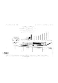
- OPERATING INSTRUCTIONS
- TABLE OF CONTENTS
- PAGE
- IMPORTANT
- WARNING
- FOR YOUR SAFETY
- FEATURES
- HOURS RECORDING AND PLAYBACK
- SUPER STILL, SUPER FINE SLOW
- MULTI-MOTION PLAYBACK
- FRONT LOADING SYSTEM
- INFRA-RED REMOTE CONTROL
- ONE-TOUCH TIMER RECORD BUTTON
- INSERT EDITING
- DAY 4 PROGRAMMABLE TIMER
- RECORDING ONE PROGRAMME WHILE WATCHING ANOTHER
- REMAINING TAPE INDICATOR
- FINE EDITING FUNCTION
- DOLBY NOISE-REDUCTION SYSTEM
- AUTO REWIND (EXCEPT TIMER RECORDING)
- ABOUT THE CASSETTE
- TYPES OF VIDEO CASSETTE
- CONTROLS AND COMPONENTS
- REAR
- ADJUSTING TV TO THE RF OUTPUT CHANNEL OF VTR
- NOTE
- VTR TUNER SETTING
- CLOCK TIME ADJUSTMENT
- BASIC OPERATION
- TO PREPARE FOR RECORDING AND PLAYBACK
- INPUT SIGNAL SELECTOR
- TAPE SELECT SWITCH
- AFTER FINISHING RECORDING OR PLAYBACK
- TO WATCH TV PROGRAMME
- BASIC FUNCTIONS
- DOLBY NOISE REDUCTION SYSTEM
- MEMORY ON/OFF SWITCH
- PICTURE SHARPNESS CONTROL
- REMAINING TAPE TIME
- RECORDING OF TV PROGRAMMES
- AFTER FINISHING RECORDING
- PLAYBACK
- PREPARE FOR PLAYBACK AS FOLLOWS
- ① PRESS PLAY BUTTON
- SUPER STILL PLAYBACK
- STILL ADVANCE PLAYBACK
- CUE PLAYBACK
- REVIEW PLAYBACK
- SUPER FINE SLOW PLAYBACK
- REVERSE PLAYBACK
- AFTER FINISHING PLAYBACK
- REVIEW, CUE
- POWER SOURCE OF WIRELESS REMOTE CONTROL
- BATTERY REPLACEMENT CAUTION
- DIRECT ACCESS OF THE MULTI-MOTION PLAYBACK
- PROGRAMMING THE TIMER FOR TIMER RECORDING
- BEFORE STARTING THE PROGRAMMING, MAKE SURE THAT
- CHECKING A TIMER RECORDING PROGRAMME
- CANCELLING A TIMER RECORDING PROGRAMME
- AFTER PROGRAMMING A TIMER RECORDING OR CHECKING PROGRAMMES
- ① SET THE TIMER RECORD SWITCH TO ON
- CAUTION
- INSERT EDITING (INSERT RECORDING)
- PREPARE FOR CAMERA RECORDING AS FOLLOWS
- TO AVOID RECORDING UNWANTED MATERIAL
- AUDIO DUBBING
- PREPARE FOR AUDIO DUBBING AS FOLLOWS
- DUBBING
- PRECAUTIONS
- AVOID SUDDEN CHANGES IN TEMPERATURE
- HUMIDITY AND DUST
- DON'T OBSTRUCT THE VENTILATION HOLES
- KEEP AWAY FROM HIGH TEMPERATURE
- KEEP MAGNETS AWAY
- NO FINGERS OR OTHER OBJECTS INSIDE
- KEEP WATER AWAY
- CLEANING THE VTR
- STACKING
- VIDEO HEAD CLOGGING
- BEFORE REQUESTING SERVICE
Brand : PANASONIC
Model : NV-777
Category : VCR