
SCC-C4339P - Soundbar Accessories SAMSUNG - Free user manual and instructions
Find the device manual for free SCC-C4339P SAMSUNG in PDF.


| Product Type | Soundbar Wall Mount Bracket |
| Compatible Soundbar Models | Samsung HW-Q600A, HW-Q700A, HW-Q800A, HW-Q900A, HW-B550, HW-B650 |
| Dimensions (W x H x D) | 950 x 50 x 40 mm |
| Weight | 1.5 kg |
| Maximum Load Capacity | 12 kg |
| Material | Steel with black corrosion-resistant coating |
| Mounting Type | Wall mount (horizontal orientation) |
| Installation Type | DIY with included hardware (wall anchors, screws) |
| Package Contents | Mounting bracket, screw pack, wall anchors, rubber spacers, user manual |
| Color | Black |
| VESA Compatibility | Not applicable (soundbar-specific) |
| Recommended TV Size | Up to 75 inches (for alignment) |
| Adjustability | Fixed angle; tilt optional via shims |
| Safety Features | Anti-slip rubber pads, secure locking mechanism |
| Maintenance | Wipe with dry cloth; avoid abrasive cleaners |
| Repairability | Spare screws available; bracket not user-serviceable |
| Warranty | 1 year (manufacturer's defect) |
Frequently Asked Questions - SCC-C4339P SAMSUNG
User questions about SCC-C4339P SAMSUNG
0 question about this device. Answer the ones you know or ask your own.
Ask a new question about this device
Download the instructions for your Soundbar Accessories in PDF format for free! Find your manual SCC-C4339P - SAMSUNG and take your electronic device back in hand. On this page are published all the documents necessary for the use of your device. SCC-C4339P by SAMSUNG.
USER MANUAL SCC-C4339P SAMSUNG
Power Zoom Camera User Manual
imagine the possibilities
Thank you for purchasing this Samsung product.
To receive more complete service, please visit our website
www.samsungsecurity.com
CAUTION
RISK OF ELECTRIC SHOCK. DO NOT OPEN

CAUTION: TO REDUCE THE RISK OF ELECTRIC SHOCK, DO NOT REMOVE COVER (OR BACK). NO USER SERVICEABLE PARTS INSIDE. REFER SERVICING TO QUALIFIED SERVICE PERSONNEL.
This symbol indicates that dangerous voltage constituting a risk of electric shock is present within this unit.

This symbol indicates that there are important operating and maintenance instructions in the literature accompanying this unit.
WARNING
- To reduce the risk of fire or electric shock, do not expose this appliance to rain or moisture.
- To prevent injury, this apparatus must be securely attached to the floor/wall in accordance with the installation instructions.
WARNING
- Be sure to use only the standard adapter that is specified in the specification sheet. Using any other adapter could cause fire, electrical shock, or damage to the product.
- Incorrectly connecting the power supply or replacing the battery may cause explosion, fire, electric shock, or damage to the product.
- Do not connect multiple cameras to a single adapter. Exceeding the capacity may cause abnormal heat generation or fire.
- Securely plug the power cord into the power receptacle. Insecure connection may cause fire.
- When installing the camera, fasten it securely and firmly. The fall of the camera may cause personal injury.
- Do not place conductive objects (e.g., screwdrivers, coins, metal parts, etc.) or containers filled with water on top of the camera. Doing so may cause personal injury due to fire, electric shock, or falling objects.
- Do not install the unit in humid, dusty, or sooty locations. Doing so may cause
2_Overview
fire or electric shock.
- If any unusual smells or smoke come from the unit, stop using the product. In such case, immediately disconnect the power source and contact the service center. Continued use in such a condition may cause fire or electric shock.
- If this product fails to operate normally, contact the nearest service center. Never disassemble or modify this product in any way. (SAMSUNG is not liable for problems caused by unauthorized modifications or attempted repair.)
- When cleaning, do not spray water directly onto parts of the product. Doing so may cause fire or electric shock.
CAUTION
- Do not drop objects on the product or apply strong blows to it. Keep away from a location subject to excessive vibration or magnetic interference.
- Do not install in a location subject to high temperature (over 50°C), low temperature (below -10°C), or high humidity. Doing so may cause fire or electric shock.
- If you want to relocate the already installed product, be sure to turn off the power and then move or reinstall it.
- Remove the power plug from the outlet when there is a lightning storm. Neglecting to do so may cause fire or damage to the product.
- Keep out of direct sunlight and heat radiation sources. It may cause fire.
- Install it in a place with good ventilation.
- Avoid aiming the camera directly towards extremely bright objects such as the sun, as this may damage the CCD image sensor.
- The apparatus shall not be exposed to dripping or splashing, and no objects filled with liquids, such as vases, shall be placed on the apparatus.
- The mains plug is used as a disconnect device and shall stay readily operable at any time.
- When using the camera outdoors, moisture may occur inside the camera due to temperature differences between indoors and outdoors. For this reason, it is recommended to install the camera indoors. For outdoor use, use the camera with built-in fan and heater.
IMPORTANT SAFETY INSTRUCTIONS
- Read these instructions.
- Keep these instructions.
- Heed all warnings.
- Follow all instructions.
- Do not use this apparatus near water.
- Clean only with dry cloth.
- Do not block any ventilation openings. Install in accordance with the manufacturer's instructions.
- Do not install near any heat sources such as radiators, heat registers, or other apparatus (including amplifiers) that produce heat.
- Do not defeat the safety purpose of the polarized or grounding-type plug. A polarized plug has two blades with one wider than the other. A grounding type plug has two blades and a third grounding prong. The wide blade or the third prong is provided for your safety. If the provided plug does not fit into your outlet, consult an electrician for replacement of the obsolete outlet.
- Protect the power cord from being walked on or pinched particularly at plugs, convenience receptacles, and the point where they exit from the apparatus.
- Only use attachments/accessories specified by the manufacturer.
- Use only with the cart, stand, tripod, bracket, or table specified by the manufacturer, or sold with the apparatus. When a cart is used, use caution when moving the cart/apparatus combination to avoid injury from tip-over.
- Unplug this apparatus during lightning storms or when unused for long periods of time.
- Refer all servicing to qualified service personnel. Servicing is required when the apparatus has been damaged in any way, such as power-supply cord or plug is damaged, liquid has been spilled or objects have fallen into the apparatus, the apparatus has been exposed to rain or moisture, does not operate normally, or has been dropped.


Apparatus shall not be exposed to dripping or splashing and no objects filled with liquids, such as vases, shall be placed on the apparatus.
4 Overview
Overview
2
4 Important Safety Instructions 5 Contents 6 Features 7 What's Included 7 Part Names and Functions
Installation & Connection
11
11 Preparing Installation 11 Connecting the Cables
Setup
14
14 Main Menu 15 Profile 17 Camera Set 26 Intelligent Video 28 Privacy Zone 29 Preset 30 Other Set 31 Communication 31 System Info 32 Language
APPENDIX
33
33 Shortcut Keys 34 Specifications
FEATURES
- With the state-of-the-art digital signal processing technology, full digital image processing and special algorithm of 600-line high resolution implemented.
- High Sensitivity: It implements images of high sensitivity using the up-to-date Super-HAD IT CCD (SCC-C4237P/C4337P) / ExView-HAD PS CCD (SCC-C4239P/C4339P).
- VPS (Virtual Progressive Scan): This is an advanced technology that reproduces a sharp progressive image. This is appropriate to high quality recording and file transfer via the Internet. (SCC-C4239P/C4339P only)
- High performance surveillance camera, equipped with x34 zoom lens and digital zoom IC, enabling monitoring up to 544 times.
- WDR extends the contrast range as it takes a picture of each of dark and bright areas before compositing the two, which is useful if you take a picture of windows inside a building. Namely, it improves the picture quality of the outdoor scenery as well as indoor. (SCC-C4239P/C4339P only)
- Low Illumination: It uses the digital signal technologies such as low illumination and Day/Night functions that make your camera identify objects even in the worst environment.
- XDR (eXtended Dynamic Range): Actively controls the gamma compensation in the way it operates the ambient luminance contrast in a certain pixel unit to determine the optimal visibility.
- Digital Power Synchronization: The full digital Line Lock function directly adjusts the vertical camera synchronization to enhance the operationability and reliability of this camera. (SCC-C4337P/C4339P only)
- DAY/NIGHT: This function can make the IR Cut filtering function inactive under the illumination below the normal value.
- White Balance to control the brightness to the illumination.
- Superior Backlight Adjustment: When an object has a bright illumination or sunlight behind it, this camera automatically improves the shaded object picture quality.
- Auto Focus to automatically adjust the focus to the subject movement
- Privacy zone to hide a specific area for personal privacy.
WHAT'S INCLUDED
Please check if your camera and accessories are all included in the product package.
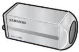
Camera
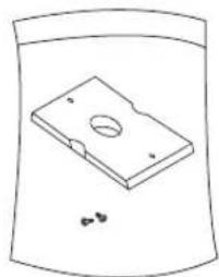
Camera Holder (Mount Adaptor) 2 Screws
User's Manual
PART NAMES AND FUNCTIONS
SIDE VIEW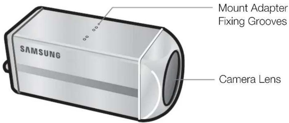

- Wipe out a dirty surface of the lens softly with a lens tissue or cloth to which you have applied ethanol.
Rear Panel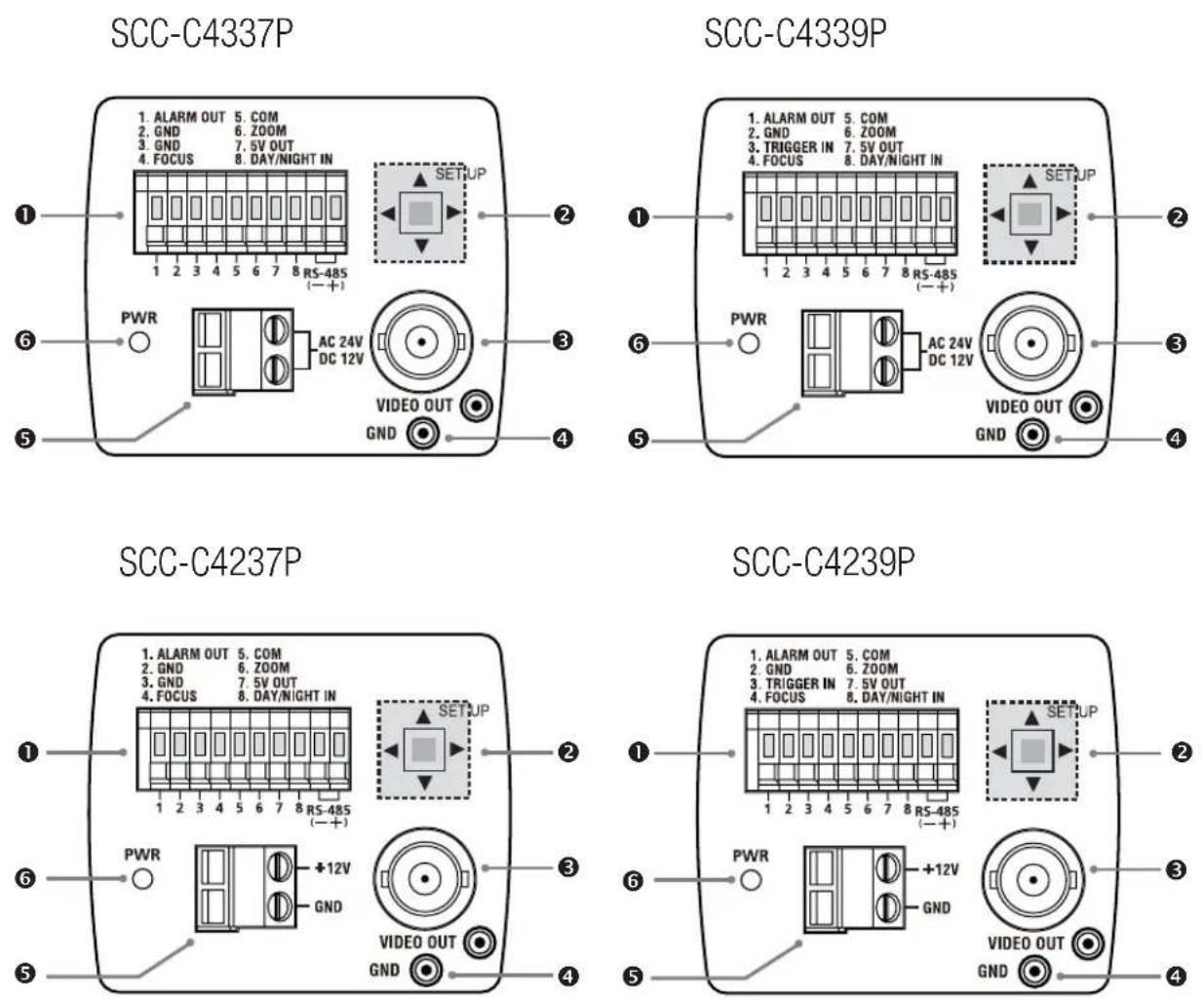
① Input/Output Connector
This connector has input and output ports for RS-485 control signals, DAY/NIGHT switching, and alarm output signals.
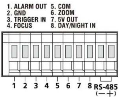
SCC-C4239P/C4339P
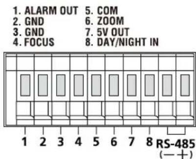
SCC-C4237P/C4337P
1. ALARM OUT
Alarm out jack for motion detection. (Open Collector, On Gnd)
2. GND
Grounding jack.
3. TRIGGER IN (SCC-C4239P/C4339P)
Displays the current still image when it receives the Trigger signal. (Normal Open Type)
4.5.6 FOCUS, COM, ZOOM
This port is used for ZOOM/FOCUS, MENU CONTROL, HOME RETURN, and ONEAF by using an external controller.
Depending on the input condition, 4 modes, A, B, C, and D are available. (SPECIAL - CTRL TYPE)
(Operation Voltage Range : +3V\~+13V, -3V\~-13V)
1) When the voltage is supplied to either ZOOM or FOCUS port
| Function *1 Code | Tele(Up) | Wide(Down) | Near(Left) | Far(Right) |
| ZOOM Port FOCUS Port | ||||
| A -6V +6V -6V +6V | ||||
| B -6V +6V +6V -6V | ||||
| C +6V -6V -6V +6V | ||||
| D | +6V -6V +6V -6V | |||
*1: During MENU OFF, controls ZOOM/FOCUS and during MENU ON, changes the direction, Up/Down/Left/Right SETUP switch. 2) When the voltage is supplied to both ports
| Function Code | ENTER/AF *2 HOME RETURN *3 | |||
| ZOOM Port | FOCUS Port | ZOOM Port | FOCUS Port | |
| A -6V -6V +6V +6V | ||||
| B -6V +6V +6V -6V | ||||
| C +6V -6V -6V +6V | ||||
| D | +6V +6V -6V -6V | |||
* 2 : For short voltage supply during MENU OFF, executes ONEAF and for more than 2 second * 3 : For more than 2 second long voltage supply, moves to the PRESET 0(HOME) position.
7.5V OUT
Power supply jack for RS-485 JIG. Use within typical DC +5V 100mA.
8. DAY/NIGHT IN
This function receives the external DAY/NIGHT signal from the sensor (optional) and converts it into a black-and-white signal.
9. RS-485 DATA-
Jack for connecting to the RS-485 DATA- signal line.
10. RS-485 DATA+
Jack for connecting to the RS-485 DATA+ signal line.
② SETUP Switch
This switch is used to set functions or properties. When pressed for at least 2 seconds, the MAIN MENU appears.
◀▶ (Left/Right): Pressing this switch left or right allows you to navigate left or right on the menu or change the displayed value.
▲▼ (Up/Down): Pressing this switch up or down allows you to navigate up or down on the menu.
☐ : Pressing this switch in the menu confirms the selected function. To enter a submenu, press this button.
③ Video OUT Port
This connects to the Video Input Port of the monitor and outputs video signals.
④ GND
This is a grounding port.
⑤ Power Connection Port
This is connected to the Power cable.
⑥ Power Display LED
When the power is normally connected, the red LED lights.
PREPARING INSTALLATION
- To install and use the camera, first prepare the following cables.
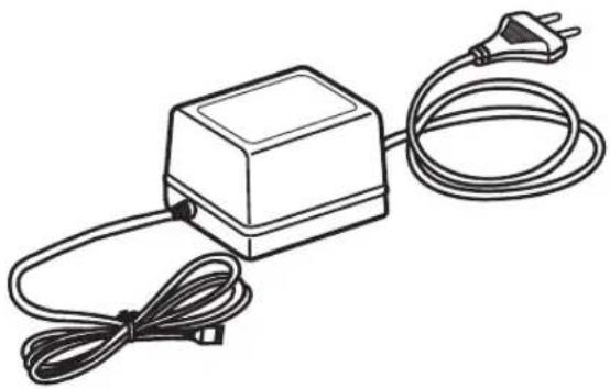
① POWER ADAPTER CABLE (SOLD SEPARATELY)
The requirements for the power adapter, which connects to the camera's POWER IN terminal, are as follows:
- SCC-C4237P/C4239P : DC 12V 600mA
- SCC-C4337P/C4339P: AC 24V 300mA
DC 12V 600mA
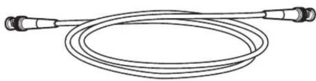
② VIDEO CABLE(SOLD SEPARATELY)
Use a BNC cable, such as the one shown below, to connect the camera's VIDEO OUT to the monitor.
INSTALLATION
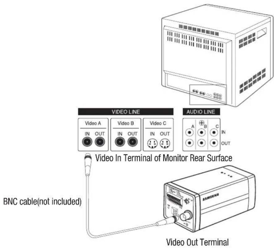
- Connect one end of the BNC cable(not included) to the VIDEO OUT.
- Connect the other end of the BNC cable (not included) to the VIDEO IN of the monitor.
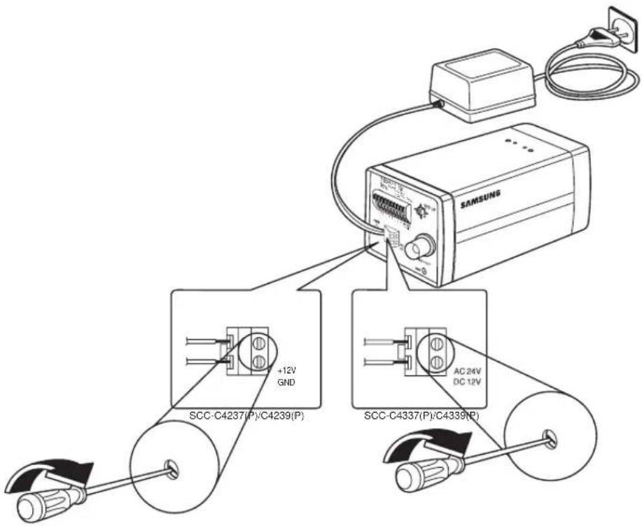
- Plug in the power adapter (not included). Use a "minus" screwdriver to connect one part of the power adapter, which consists of two lines, to the POWER terminal of the camera as follows:
12_ installation & connection
- Determine the type of power supply and set the POWER SELECTION switch accordingly. Next, plug the power adapter into a wall outlet.
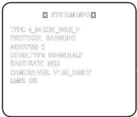
- If the camera operates normally, the following screen will be displayed for 5 seconds and then disappears.
- The requirements for RS485 control are as follows:
- Signaling Speed: 9600 bps
- Data Bit: 8 bits
- Stop Bit: 1 bit
- Parity Bit: none
Using OSD icons
- ◀▶: If these icons appear in the left and right corner of a menu item, you can use them to move to the previous or next menu.
- (EXIT): Exits the menu setup screen. Before exiting the setup screen, select to save your settings to the whole menus, or to cancel them.
- (RET): Saves your settings and returns to the previous screen. • (HOME): Returns to the main menu.
- (SAVE): Use this icon if you want to save your settings after you specified the mask area and privacy area, etc.
Once you saved your settings, the changes remain intact even if you select on exit.
- (DEL): Use this icon if you want to delete a mask, or privacy area, etc. Once you deleted your settings, the deletions remain valid even if you select on exit.
- ←: This icon appears in the right of a menu containing sub menu items.
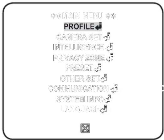
MAIN MENU
This is the first screen you ever see when you turn on the camera where you can set the camera environment to your needs.
- PROFILE
Select a mode appropriate to the camera installation environment.
- CAMERA SET
You can configure the camera settings.
• INTELLIGENCE
Offers motion detection and tracking functions.
- PRIVACY ZONE
You can configure the privacy settings.
- PRESET
You can set the PRESET POSITION.
- OTHER SET
You can reset the camera, or adjust the OSD color to your preference.
• COMMUNICATION
Configures the settings pertaining to RS-485 communication.
- SYSTEM INFO
Shows the system information such as the camera version or communication settings.
- LANGUAGE
Select a preferred one from the supported languages.
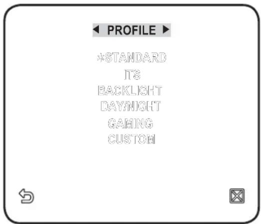
PROFILE
You can select one from the pre-determined configurations as appropriate to your specific camera installation environment.
Your selection on each item in PROFILE will affect all other settings of the camera.
- STANDARD
Automatically optimizes the camera settings to the normal environment.
• ITS
This setting enables you to analyze the traffic situation and take the traffic information at a glance.
- BACKLIGHT
This setting enables you to view a sharp background and object even in a severe backlight scene.
- DAY/NIGHT
Automatically optimizes the camera settings to the day and night scene.
• GAMING
This automatically configures the settings so that you can work in a stable illumination condition as indoors.
- CUSTOM
Your change to any of the PROFILE settings will switch the display to CUSTOM.
| CAMERA SETUP MENU | STANDARD ITS BACKLIGHT DAY/NIGHT GAMING | |||||
| Parent Menu | Sub-menus | |||||
| VPS OFF | ON OFF OFF OFF | |||||
| IRIS | ALC ALC ALC ALC ALC | |||||
| ALC - | - | - | - | - | ||
| LEVEL 0 | 0 | 0 | 0 | 0 | ||
| BACKLIGHT OFF OFF WDR OFF OFF | ||||||
| WDR - | - | - | - | - | ||
| WEIGHT | Custom Setting | Custom Setting | MEDIUM | Custom Setting | Custom Setting | |
| WDR LEVEL | Custom Setting | Custom Setting | 0 | Custom Setting | Custom Setting | |
| WHITE BAL | Custom Setting Custom Setting Custom Setting Custom Setting Custom Setting | Setting | ||||
| MOTION | (F.FAST)--- | (F.FAST)--- | NORM | (F.FAST)--- | SLOW | |
| DNR | MEDIUM | MEDIUM | MEDIUM | MEDIUM | MEDIUM | |
| SHUTTER | OFF OFF OFF OFF | |||||
| SENSE UP | AUTO X4 | AUTO X2 | AUTO X4 | AUTO X4 | AUTO X4 | |
| XDR | MEDIUM | MEDIUM | MEDIUM | MEDIUM | MEDIUM | |
| DAY/NIGHT | AUTO | AUTO | DAY | AUTO | DAY | |
| NIGHT | - | - | - | - | - | |
| BURST OFF ON OFF OFF OFF | ||||||
| EXT | - | - | - | - | - | |
| BURST | - | - | - | - | - | |
| WHITE BAL | DAY DAY/NIGHT DAY DAY/NIGHT DAY | |||||
| DAY | - | - | - | - | - | |
| MODE | ATW2 | ATW1 | ATW1 | ATW1 | ATW1 | |
| RED 0 | 0 | 0 | 0 | 0 | ||
| BLUE 0 | 0 | 0 | 0 | 0 | ||
| NIGHT | - | - | - | - | - | |
| BRIGHTNESS | - | MEDIUM | - | MEDIUM | - | |
| MODE | OFF | ATW2 | OFF | ATW2 | OFF | |
| RED | - | 0 | - | 0 | - | |
| BLUE | - | 0 | - | 0 | - | |
| DETAIL | 2 | 2 | 2 | 2 | 2 | |
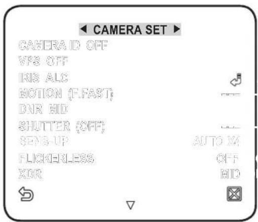
You can configure the general settings of the camera module.
- Select - . The Camera Setup menu appears.
- Change the settings as necessary, or select an item to check.
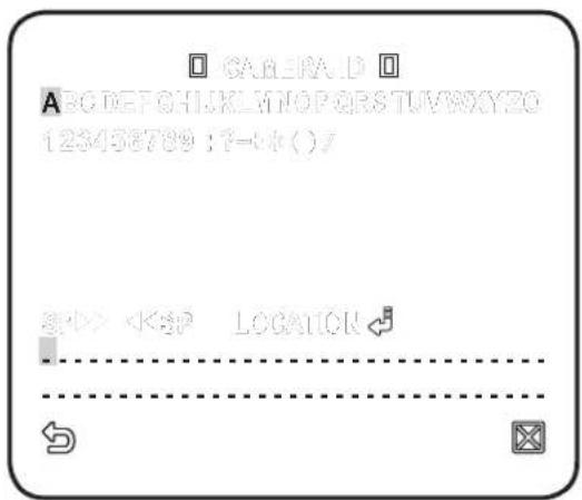
CAMERA ID
Provide the ID and location for a camera that displays on the screen.
- Select - .
- Use ▲▼◀▶ to select a desired character, then press [ENTER].
In the lower input box of the screen, the selected character will be entered.
■ You can enter up to 54 characters including alphabets, numbers and special characters. - LOCATION : Specify the display position of the camera ID.
AGC
With this, you can adjust the AGC level of a camera. With AGC active, if the signal strength falls below the standard level, AGC will amplify the video signal to automatically improve the sensitivity. IfMOTION
You can specify a level of AGC for controlling the camera motion. This is available only of the SENSE UP menu is set to AUTO. Select F.FAST if you want to monitor a very fast moving object in a low contrast scene, and S.SLOW if monitoring a very slow moving, inanimate object in the same condition. As long as DAY/NIGHT is set toDNR
Reduces the noise on the camera image. The higher the level is, the greater the effect is. Set it toSHUTTER
You can select a fixed fast electronic shutter speed in 7 options ranging from 1/120 to 1/10k, which is mostly used to take a picture of a fast moving object. As long as SENSE UP is set to AUTO, FIXED / FLICKERLESS to ON / BACKLIGHT to WDR, the SHUTTER menu is not available.SENS-UP
 Automatically senses the darkness level at night or in a low contrast scene, and extends the accumulation time accordingly; you can selectFLICKERLESS
This will prevent possible screen distortion due to a mismatch between the vertical sync frequency and the blinking frequency of the lighting; if set toXDR
This will correct a brightness difference between different scenes for the optimal visibility by calculating the ambient luminance contrast in a certain unit of pixels. The higher the value is, the higher the correction level is.DAY/NIGHT
You can specify a recording mode according to the scene. 1. SelectWHITE BAL
If you need to adjust the color according to the ambient illumination, you can use theFOCUS MODE
You can select a focus mode according to the angle that you adjusted for camera recording. \- AF : This will monitor the screen continuously to focus automatically. If you adjust the focus manually, that will operate the same as inZOOM SPEED
You can adjust the zoom operation speed.DISPLAY ZOOM
You can set to display the zoom status on the screen. It will disappear in about 3 seconds if the zoom factor has no further change.DIGITAL ZOOM
You can set the maximum allowable digital zoom ratio. Digital Zoom will start operation after it is zoomed in to the maximum optical ratio of x34. If you set DIGITAL ZOOM to x16, you can take a shot at up to x544 (34x16). When you set DISPLAY ZOOM as on, you may see zoom value on the screen.DETAIL
Used to adjust the vertical and horizontal distinction, respectively.V-SYNC
You can set the V-SYNC mode. - If you selectAGC COLOR SUP
You can adjust the color reproduction range according to AGC.REVERSE
You can reverse the video signal from left to right, upside down, or vice versa to your convenience. POSI/NEGA
You can set the video brightness signal to normal or reverse.PIP
You can view a main image with a sub image on the same screen.  If more than one PRIVACY ZONE is specified, and PRIVACY SET toDIS
If you set it toINTELLIGENT VIDEO
You can enable the motion detection and tracking functions. 1. SelectMOTION
You can enable the motion detection and tracking functions.   If you set it toADVANCED
You can detect motions and mark the video that contains such motion, and enables tracking of the movement. Selecting theMASK AREA
1. Select the number of the area to be masked that will be excluded from motion detection. 2. Select the mask number and set the mask size and its coverage.  DISPLAY
When selectedSENSITIVITY
Sets the sensitivity of motion sensor.RESOLUTION
The bigger the resolution setting, the smaller the object that can be detected.ALARM OUT
When selectedPRIVACY ZONE
You can set up to 12 privacy zones that will be hided for privacy of the subject when recording.Zone Setup
1. Select

- POWER ZOOM CAMERA USER MANUAL
- CAUTION
- WARNING
- OVERVIEW
- IMPORTANT SAFETY INSTRUCTIONS
- INSTALLATION & CONNECTION
- SETUP
- APPENDIX
- FEATURES
- WHAT'S INCLUDED
- PART NAMES AND FUNCTIONS
- ① INPUT/OUTPUT CONNECTOR
- ALARM OUT
- GND
- TRIGGER IN (SCC-C4239P/C4339P)
- FOCUS, COM, ZOOM
- V OUT
- DAY/NIGHT IN
- RS-485 DATA
- ② SETUP SWITCH
- ③ VIDEO OUT PORT
- ④ GND
- ⑤ POWER CONNECTION PORT
- ⑥ POWER DISPLAY LED
- PREPARING INSTALLATION
- INSTALLATION
- USING OSD ICONS
- MAIN MENU
- PROFILE
- CAMERA SET
- INTELLIGENCE
- PRIVACY ZONE
- PRESET
- OTHER SET
- CAMERA ID
- VPS
- IRIS
- AGC
- MOTION
- DNR
- SHUTTER
- SENS-UP
- FLICKERLESS
- XDR
- DAY/NIGHT
- WHITE BAL
- FOCUS MODE
- ZOOM SPEED
- DISPLAY ZOOM
- DIGITAL ZOOM
- DETAIL
- V-SYNC
- AGC COLOR SUP
- REVERSE
- POSI/NEGA
- PIP
- DIS
- INTELLIGENT VIDEO
- ADVANCED
- MASK AREA
- DISPLAY
- SENSITIVITY
- RESOLUTION
- ZONE SETUP
- EXTERNAL TRG
- FACTORY DEFAULTS
- OSD COLOR
- CTRL TYPE
- COMMUNICATION
- SYSTEM INFO
- LANGUAGE
- SHORTCUT KEYS
- SAMSUNG
- CORRECT DISPOSAL OF THIS PRODUCT (WASTE ELECTRICAL & ELECTRONIC EQUIPMENT)
- МОЩНАЯ КАМЕРА С ТРАНСФОКАТОРОМ
- ВНИМАНИЕ
- ПРЕДУПРЕЖДЕНИЕ
- ВАЖНЫЕ ПРАВИЛА ТЕХНИКИ БЕЗОПАСНОСТИ
- ОБЗОР
- УСТАНОВКА И ПОДКЛЮЧЕНИЕ
- НАСТРОЙКА
- ПРИЛОЖЕНИЕ
- ФУНКЦИИ
- КОМПОНЕНТЫ ВИДЕОКАМЕРЫ И ИХ НАЗНАЧЕНИЕ
- ① РАЗЪЕМ ВХОДОВ/ВЫХОДОВ
- TRIGGER IN (ТОЛЬКО SCC-C4239P/C4339P)
- ② ПЕРЕКЛЮЧАТЕЛЬ SETUP (НАСТРОЙКА)
- ПОДГОТОВКА К УСТАНОВКЕ
- ПОДСОЕДИНЕНИЕ КАБЕЛЕЙ
- ИСПОЛЬЗОВАНИЕ ЭКРАННЫХ ЗНАЧКОВ
- ОСНОВНОЕ МЕНЮ
- ПРОФИЛЬ
- НАСТР. КАМЕРЫ
- С-МА ОТСЛЕЖ-Я
- ЧАСТНАЯ ЗОНА
- ПРЕДУСТ
- ДР. НАСТРОЙКИ
- СВЯЗЬ
- ИНФ. О СИСТЕМЕ
- ЯЗЫК
- СТАНДАРТНЫЙ
- ITS
- ФОНОВ.CBET
- ДЕНЬ/НОЧЬ
- ИГРА
- ПОЛЬЗОВ
- ID КАМЕРЫ
- ДИАФРАГМА
- APY
- ДВИЖЕНИЕ
- ATBOP
- НАКОПЛЕНИЕ
- НЕМЕРЦАЮЩЕЕ
- БАЛАНС БЕЛОГО
- РЕЖИМ ФОКУС
- СКОР. ТРАНСФОК
- ИНД.ЗУМА
- ЦИФР УВЕЛИЧЕНИЕ
- ЧЕТКОСТЬ
- КАДР СИНХР
- АРУ ЦВЕТА
- ИНВЕНТИР
- ПОЗ/НЕГАТИВ
- ИНТЕЛЛЕКТУАЛЬНОЕ ВИДЕО
- УЛУЧШЕННЫЙ
- ЗОНА МАСКИР
- ДИСПЛЕЙ
- ЧУВСТВИТЕЛЬН
- РАЗРЕШЕНИЕ
- ВЫХОД ТРЕВОГИ
- НАСТРОЙКА ЧАСТНОЙ ЗОНЫ
- BHEWH.TRG
- ЗАВОД.УСТАН
- ЦВЕТНОЕ
- ТИП УПРАВ
- КЛАВИШИ БЫСТРОГО ДОСТУПА
- ПРАВИЛЬНАЯ УТИЛИЗАЦИЯ ДАННОГО УСТРОЙСТВА (УТИЛИЗАЦИЯ ЭЛЕКТРИЧЕСКОГО И ЭЛЕКТРОННОГО ОБОРУДОВАНИЯ)
- KAMERA POWER ZOOM INSTRUKCJA OBSŁUGI
- UWAGA
- OSTRZEŻENIE
- INFORMACJE OGÓLNE
- WAŻNE ZALECENIA DOTYCZĄCE BEZPIECZEŃSTWA
- INSTALACJA I PODŁĄCZENIE
- USTAWIENIA
- DODATEK
- FUNKCJE
- CO ZOSTAŁO DOSTARCZONE
- NAZWY CZEŚCI I FUNKCJE
- WIDOK Z BOKU
- ① ZŁĄCZA WEJŚCIA/WYJŚCIA
- ② PRZEŁĄCZNIK KONFI GURACJI
- ③ GNIAZDO VIDEO OUT
- ⑤ GNIAZDO ZASILANIA
- ⑥ WSKAŹNIK LED ZASILANIA
- PRZYGOTOWANIE INSTALACJI
- PODŁĄCZENIE KABLI
- KORZYSTANIE Z IKON MENU EKRANOWEGO
- MENU GŁÓWNE
- PROFIL
- UST. KAMERY
- ID KAMERY
- PRZYSLONA
- RUCH
- MIGAWKA
- CZULOSC
- KOMP. MIGOTANIA
- DZIEN/NOC
- BALANS BIELI
- TRYB FOCUS
- PREDKOSC ZOOMU
- WYSWIETL.ZOOM
- ZOOM CYFROWY
- DETAL
- SYN.-PION
- AGC KOLOR SUP
- ODWROC
- INTELIGENTNE WIDEO
- DET. RUCH
- OBSZAR MASKI
- WYŚWIETL
- ROZDZIELCZOSC
- WYJ. ALARMOWE
- STREFA PRYWATNOŚCI
- KONFIGUROWANIE STREFY
- UST. WST
- INNE USTAWIENIA
- DOMYSLNE UST. FAB
- KOLOR
- RODZAJ STER
- KOMUNIKACJA
- INFO O SYSTEMIE
- JEZYK
- KLAWISZE SKRÓTÓW
- PRAWIDŁOWE USUWANIE PRODUKTU (ZUŻYTY SPRZĘT ELEKTRYCZNY I ELEKTRONICZNY)
- KAMERA S MOTOROVÝM ZOOMEM
- UŽIVATELSKÁ PŘÍRUČKA
- UPOZORNĚNÍ
- PŘEHLED
- DŮLEŽITÉ BEZPEČNOSTNÍ POKYNY
- INSTALACE A ZAPOJENÍ
- NASTAVENÍ
- PŘÍLOHA
- FUNKCE
- SOUČÁSTI BALENÍ
- NÁZVY SOUČÁSTÍ A FUNKCE
- POHLED ZE STRANY
- ① VSTUPNÍ/VÝSTUPNÍ KONEKTOR
- TRIGGER IN (POUZE SCC-C4239P/C4339P)
- ② SPÍNAČ SETUP
- PŘÍPRAVA INSTALACE
- PŘIPOJENÍ KABELŮ
- POUŽITÍ IKON OSD
- HLAVNÍ NABÍDKA
- NASTAVENÍ KAMERY
- CLONA
- POHYB
- ZÁVĚRKA
- ZVÝŠ. CITL
- BEZ BLIKÁNÍ
- DEN/NOC
- VYVÁŽENÍ BÍLÉ
- REŽIM OSTŘENÍ
- RYCHL. ZVĚTŠ
- ZOBRAZIT ZOOM
- DIGITÁLNÍ ZOOM
- POTL. BARVA AGC
- OPAČNÝ
- POZI/NEGA
- POUŽITÍ KAMERY KE SLEDOVÁNÍ
- POKROČILÝ
- MASKA OBLASTI
- ZOBRAZENÍ
- CITLIVOST
- ROZLIŠENÍ
- POPLACH. VÝSTUP
- PRIVÁTNÍ ZÓNA
- NASTAVENÍ ZÓNY
- PREPOZICE
- DALŠÍ NASTAVENÍ
- EXTERNÍ TRG
- TOVÁRNÍ NAS
- BARVA OSD
- TYP OVLÁDÁNÍ
- KOMUNIKACE
- SYST. INFORMACE
- JAZYK
- KLÁVESOVÉ ZKRATKY
- SPRÁVNÁ LIKVIDACE VÝROBKU (ELEKTRICKÝ A ELEKTRONICKÝ ODPAD)
- ELEKTRIKLI ZOOM KAMERA KULLANICI KILAVUZU
- DİKKAT
- UYARI
- ÖNEMLI GÜVENLIK YÖNERGELERI
- GENEL BILGILER
- KURULUM VE BAĞLANTI
- AYARLAR
- EK
- ÖZELLIKLER
- DAHIL OLANLAR
- PARÇA ADLARI VE İŞLEVLERİ
- ① GIRIŞ/ÇIKIŞ KONEKTÖRÜR
- TRIGGER IN (SADECE SCC-C4239P/C4339P)
- KURULUMA HAZIRLIK
- KABLOLARIN BAĞLANMASI
- OSD SIMGELERININ KULLANILMASI
- ANA MENÜ
- PROFİL
- KAMERA TANIM
- HAREKET
- ÖRTÜCÜ
- ALGILAMA
- FREK. DÜZELT
- GÜNDÜZ/GECE
- BEYAZ DENGESİ
- FOKUS MODU
- ZOOM HIZI
- ZOOM GÖRÜNTÜLE
- DİJİTAL ZOOM
- DETAY
- AGC RENK BAS
- ÇEVİR
- AKILLI VIDEO
- GELİŞMİŞ
- ALAN MASKESİ
- EKRAN
- HASSASİYET
- ÇÖZÜNÜRLÜK
- ALARM ÇIKİŞ
- GIZLİ BÖLGE
- BÖLGE AYARI
- ÖNAYAR
- DİĞER AYARLAR
- HARİCİ TETİK
- FABRİKA AYARLARI
- CTRL TIPI
- İLETİŞİM
- SİSTEM BİLGİSİ
- DIL
- KISAYOL TUŞLARI
Brand : SAMSUNG
Model : SCC-C4339P
Category : Soundbar Accessories