
Altos T110 F4 - Server ACER - Free user manual and instructions
Find the device manual for free Altos T110 F4 ACER in PDF.
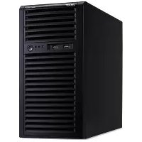


| Product Type | Tower Server |
| Brand | Acer |
| Model | Altos T110 F4 |
| Processor | Intel Xeon E3-1200 v6 or Intel Core i3 (7th Gen) |
| Chipset | Intel C236 |
| Memory | Up to 64 GB DDR4 ECC, 4 slots |
| Storage | Up to 4 x 3.5" SATA/SAS hot-swap bays |
| RAID Support | Onboard SATA RAID 0/1/10/5 (Intel RSTe); optional hardware RAID |
| Network | Dual Intel Gigabit Ethernet |
| Expansion Slots | 1 x PCIe 3.0 x16, 1 x PCIe 3.0 x4, 1 x PCIe 3.0 x1, 1 x PCI |
| Power Supply | 300 W single (non-hot-plug) |
| Form Factor | Tower (5U) |
| Dimensions (H x W x D) | 381 x 175 x 429 mm (15.0 x 6.9 x 16.9 in) |
| Weight | Approximately 12.5 kg (27.6 lb) |
| Operating Temperature | 5°C to 35°C (41°F to 95°F) |
| Non-Operating Temperature | -40°C to 70°C (-40°F to 158°F) |
| Cooling | 1 x System fan (non-hot-plug) |
| Management | Acer Smart Setup, IPMI 2.0 (optional) |
| Operating System Support | Windows Server, Linux, VMware ESXi |
| Maintenance | Tool-less access to internal components; easy to replace HDDs, RAM, and fan |
| Cleaning | Use compressed air to remove dust from vents and fans; avoid liquids |
| Safety | Complies with FCC, CE, UL, etc.; operate in well-ventilated area |
| Spare Parts and Repairability | Spare parts available (PSU, fan, HDD caddy, etc.); user-serviceable with basic tools |
Frequently Asked Questions - Altos T110 F4 ACER
User questions about Altos T110 F4 ACER
0 question about this device. Answer the ones you know or ask your own.
Ask a new question about this device
Download the instructions for your Server in PDF format for free! Find your manual Altos T110 F4 - ACER and take your electronic device back in hand. On this page are published all the documents necessary for the use of your device. Altos T110 F4 by ACER.
USER MANUAL Altos T110 F4 ACER
Workstation Altos T110 F4

USER'S MANUAL
Revision 1.0
Preface
About this Manual
This manual is written for professional system integrators and PC technicians. It provides information for the installation and use of the Workstation. Installation and maintenance should be performed by experienced technicians only.
Notes
For your system to work properly, please follow the links below to download all necessary drivers/utilities and the user's manual for your workstation.
- product manuals:
Warnings
Special attention should be given to the following symbols used in this manual.

Warning! Indicates important information given to prevent equipment/property damage or personal injury.

Warning! Indicates high voltage may be encountered when performing a procedure.
Table of Contents
Chapter 1 Introduction
1.1 Overview......8 1.2 Unpacking the System 8 1.3 System Specifications....9 1.4 Server Chassis Features....10
Control Panel....10 Front Features.... 11 Rear Features 12
1.5 Motherboard Layout....13
Quick Reference Table....14
Chapter 2 Workstation Setup
2.1 Overview....17 2.2 Preparing for Setup 17
Choosing a Setup Location 17
Server Precautions....17
Chapter 3 Maintenance and Component Installation
3.1 Removing Power 19 3.2 Accessing the System 19 3.3 Motherboard Components 20
Processor and Heatsink Installation 20 Memory Installation 25 Memory Support 25 DIMM Module Population Sequence 26 PCI Expansion Card Installation....27 Motherboard Battery 27
3.4 Chassis Components....28
Hard Drives 28 Optional Drive Bays....30 System Cooling 31
Replacing the System Fan....31
Power Supply 32
Chapter 4 Motherboard Connections
4.1 Power Connections....33
4.2 Headers and Connectors....34
Control Panel 39
Data Cables 42
Power Cables 42
4.3 Ports 43
Rear I/O Ports....43
4.4 Jumpers....45
Explanation of Jumpers....45
4.5 LED Indicators 49
Chapter 5 Software
5.1 OS Installation....51
Installing the Windows OS for a RAID System....51
Installing Windows to a Non-RAID System....51
5.2 Driver Installation 52
5.3 SuperDoctor® 5....53
5.4 IPMI 54
Chapter 6 BIOS
6.1 Introduction 55
Starting the Setup Utility....55
6.2 Main Setup 56
6.3 Advanced Setup Configurations....58
6.4 Event Logs....83
6.5 IPMI 85
6.6 Security......88
6.7 Boot 91
6.8 Save & Exit....93
Appendix A BIOS Error Codes
Appendix B Standardized Warning Statements for AC Systems
Appendix C System Specifications
Chapter 1
Introduction
1.1 Overview
This chapter provides a brief outline of the functions and features of the T110 F4.
In addition to the motherboard and chassis, several important parts that are included with the system are listed below.
| Main Parts List | ||
| Description | Part Number | Quantity |
| Fans (4-cm, PWM) | FAN-0108L4 | 1 |
| Internal 3.5" HDD Drive Trays | MCP-220-73101-0B | 4 |
1.2 Unpacking the System
Inspect the box the Workstation T110 F4 was shipped in and note if it was damaged in any way. If any equipment appears damaged, please file a damage claim with the carrier who delivered it.
The system should be situated in a clean, dust-free area that is well ventilated. Avoid areas where heat, electrical noise and electromagnetic fields are generated. It will also require a grounded AC power outlet nearby. Be sure to read the precautions and considerations noted in Appendix B.
1.3 System Specifications
The following table provides you with an overview of the main features and specifications of the T110 F4. Please refer to Appendix C for additional specifications.
| System Specifications |
| Motherboard |
| X11SSL-F |
| Chassis |
| SC731-3008 |
| CPU |
| Intel® E3-1200 v6 and 6th Gen CoreTM i3, Pentium and Celeron processors |
| Socket Type |
| LGA 1151 (H4) |
| Memory |
| Four 268-pin DIMM slots to support up to 64 GB of 72-bit, unbuffered ECC DDR4-2133/1866/1600/1333 SDRAM |
| Chipset |
| C232 chipset |
| Expansion Slots |
| One PCI Express 3.0 x4 in x8 slots (PCH slot 5)One PCI Express 3.0 x8 in x16 slot (CPU slot 6)One PCI Express 3.0 x8 slot (CPU slot 7) |
| Hard Drives |
| Up to four 3.5" internal drives |
| Power |
| Single 300W low-noise power supply with PFC |
| Form Factor |
| Mini tower |
| Dimensions |
| (WxHxD) 7.25 x 14.25 x 16.75 in. (184 x 362 x 425 mm) |
1.4 System Chassis Features
Control Panel
The switches and LEDs located on the control panel are described below. See Chapter 4 for more details on the control panel.
Figure 1-1. Control Panel View
| Control Panel Features | ||
| Item | Feature | Description |
| 1 | USB Port | Front access USB port |
| 2 | Information LED | See table below |
| 3 | HDD LED | Indicates activity on the hard drive when flashing |
| 4 | NIC1 LED | Indicates network activity on the LAN port when flashing |
| 5 | Power Button | The main power button is used to apply or remove power from the power supply to the server. Turning all system power with this button removes the main power but maintains standby power. To perform many maintenance tasks, you must also unplug system before servicing |
| Information LED | |
| Status | Description |
| Continuously on and red | An overall condition has occurred.(This may be caused by cable, tangestion.) |
| Blinking red (1Hz) | Fan failure, check for an inoperative fan. |
| Solid blue | Local UID has been activated. Use this function to locate the server in a rackmount environment. |
| Blinking blue | Remote UID is on. Use this function to identify the server from a remote location. |
Front Features
The T110 F4 is a mini-tower chassis. See the illustration below for the features included on the front of the chassis.

Figure 1-2. Chassis Front View
| Front Chassis Features | ||
| Item | Feature | Description |
| 1 | Fixed Drive Area | Supports two fixed 5.25" drives (such as a DVD-ROM or Blu-ray drive) |
| 2 | Control Panel | Front control panel with LEDs and buttons (see preceding page) |
| 3 | Internal HDD Cage (behind level) | Supports four 3.5" hard drives in a rotatable cage |
Rear Features
The illustration below shows the features included on the rear of the chassis.

Figure 1-3. Chassis Rear View
| Rear Chassis Features | ||
| Item | Feature | Description |
| 1 | Power Supply | 300W 80Plus Bronze Level power supply (pV: PWS-305-PQ) |
| 2 | I/O Backpanel | Rear I/O ports (see Section 4.3) |
| 3 | PCI Slots | Supports four full height, full-length PCI expansions, cards |
1.5 Motherboard Layout
Below is a layout with jumper, connector and LED locations shown. See the table on the following page for descriptions. For detailed descriptions, pinout information and jumper settings, refer to Chapter 5.

Figure 1-4. Motherboard Layout
Notes:
indicates the location of pin 1.
Jumpers/LED indicators not indicated are used for test purposes only.
The COM2, PCI-E Slot 4, I-SATA6 and I-SATA 7 ports shown above are not included on the X11SSL-F.
Quick Reference Table
| Jumper | Description | Default Setting |
| JPC1/JPC2 | SMD to PCI Slots Enable/Disable | Pins 1-2 (Enabled) |
| JSR1 | BIOS Recovery | Pins 1-2 (Normal) |
| JGT1 | Clear CMOS | Open (Normal) |
| JPBI | BMC Enable/Disable | Pins 1-2 (Enabled) |
| JPGI | VGA Enable/Disable | Pins 1-2 (Enabled) |
| JPL1/NPL2 | LAN1/LAN2 Enable/Disable | Pins 1-2 (Enabled) |
| JPME2 | Manufacturing Mode Select | Pins 1-2 (Normal) |
| JWD1 | Watch Dog | Pins 1-2 (Reset) |
| LED | Description | Status |
| LE1 | Roar UID LED | Blue: On; Unit Identified |
| LEDRMC | BMC Haarmast LED | Green: Blinking; BMC Normal |
| LEDPWR | Onboard Power LED | Green: Solid On; Power On |
| Connector | Description | |
| BT1 | Onboard Battery | |
| COM1 | COM1 (Serial Port) Header | |
| Fan1-Fan4, FanA | System/CPU Fan Headers | |
| (JPM) LAN | Dedicated IPMI (RJ45) Port | |
| I-SATA0-I-SATA5 | Intel PCH SATA (Serial ATA) 3.0 Ports | |
| I-SSPIO 1/2 | Serial Link General Purpose I/O Headers | |
| JO1 | Speaker/Power LED Indicator | |
| JF1 | Front Panel Control Header | |
| JIPMB1 | 4-pin External BMC 12C Header (for an IPMI Card) | |
| JL1 | Chassis Infusion Header | |
| JPPC1 | Power System Management Bus (Power, SMB) | |
| JON1 | Overheat LED Indicator | |
| JPWR1 | 24-pin ATX Main Power Connector (Required Connection) | |
| JPWR2 | +12V 8-pin Power Connector | |
| JSD1/JS02 | SATA DOM (Device Or Module) Power Connectors | |
| JSTDY1 | Inject External PSV Standby Power | |
| JTPM1 | Trusted Platform Module/Port 80 Connector | |
| JUID81 | Unit Identifier Switch | |
| LAN1/LAN2 | Gigabit (RJ45) Ports | |
| PCI-E (CPU) Slot 7 | PCI-Express 3.0 x8 Slot | |
| PCI-E (CPU) Slot 8 | PCI Express 2.0 x8 in x16 Slot |
Table continued on next page.
| Connector | Description |
| PCI-E (PCI-1) Slot 5 | PCI-Express 3.0 x4 in x6 Slot |
| SP1 | Internal Speaker/Buzzer |
| USB 0/1 | Back Panel USB 2.0 Ports |
| USB 2/3, USR 4/5 | Front Accessible USB 2.0 Headers |
| USB 6/7 | Back Panel USB 3.0 Ports |
| USB 8/9 | Front Accessible USB 3.0 Header |
| USB 10 | USB 3.0 Type-A Header |
| VGA | VGA Port |
Connector Description: VGA Part
![graph TD A["MCV8 & 3 PHASE for Voicing (WTV)"] --> B["PGC10.5 x8 (in x8)"] A --> C["PGC10.5 x8 (in x8)"] B --> D["PCI-E X3 Gen3"] C --> E["PCI-E X3 Gen3"] D --> F["SLC-H4 LGA1101"] E --> G["SLC-H4 LGA1101"] F --> H["DM3"] G --> I["DM3 x4"] H --> J["DM3 x4"] I --> K["PCH"] J --> K K --> L["PCI-E x4 G…](/content/2026/05/1002718/images/2524ceb2cfa34a52c01424cda4df1bc1a2c0b12e12bbfd719b42026fbcfb5e31.jpg)
Figure 1-5. C232 Chipset Block Diagram
Note: This is a general block diagram and may not exactly represent the features on your motherboard. Note the differences marked between the X11SSL-F (included in the T110 F4) and the X11SSM. See Appendix C for the actual specifications of your motherboard.
Chapter 2
Workstation Setup
2.1 Overview
This chapter provides advice on setting up your system. If your system is not already fully integrated with processors, system memory, etc., refer to Chapter 4 for details on installing those specific components.
Caution: Electrostatic Discharge (ESD) can damage electronic components. To prevent such damage to PCBs (printed circuit boards), it is important to use a grounded wrist strap, handle all PCBs by their edges, and keep them in anti-static bags when not in use.
2.2 Preparing for Setup
Precautions
• Review the electrical and general safety precautions in Appendix B. - Use a regulating uninterruptible power supply (UPS) to protect the workstation from power surges and voltage spikes and to keep your system operating in case of a power failure. - Allow any drives and power supply modules to cool before touching them. - When not servicing, always keep all covers/panels on the system closed to maintain proper cooling.
Chapter 3
Maintenance and Component Installation
This chapter provides instructions on installing and replacing main system components. To prevent compatibility issues, only use components that match the specifications and/or part numbers given.
Installation or replacement of most components requires that power first be removed from the system. Please follow the procedures given in each section.
3.1 Removing Power
Use the following procedure to ensure that power has been removed from the system. This step is necessary when removing or installing non-hot-swap components or when replacing a non-redundant power supply.
- Use the operating system to power down the system.
- After the system has completely shut down, disconnect the AC power cord from the power strip or outlet.
- Disconnect the power cord from the power supply module.
3.2 Accessing the System
The left side cover of the SC731i-300B must be removed before replacing the system fan or installing and removing hard drives.
Removing the Top Cover
- Begin by removing power from the system as described in Section 3.1.
- Slide the release tab (A) towards the cover handle (B).
- Grasp the cover handle with your fingers and slide it toward the rear of the chassis.
- Remove the cover from the chassis. See Figure 3-1.
Warning: Except for short periods of time, do not operate the system without the cover in place. The chassis cover must be in place to allow for proper airflow and to prevent overheating.

Figure 3-1. Accessing the System
3.3 Motherboard Components
Processor and Heatsink Installation
Follow the procedures in this section to install a processor (CPU) and heatsink to the motherboard.
Notes:
- The motherboard should be installed into the chassis first and the processor should be installed into the CPU socket before you install a CPU heatsink.
- If you bought a CPU separately, make sure that you use an Intel-certified multi-directional heatsink only.
- When receiving a motherboard without a processor pre-installed, make sure that the plastic CPU socket cap is in place and none of the socket pins are bent; otherwise, contact your retailer immediately.
• Refer to the Supermicro website for updates on CPU support.
Installing the Processor(s)
Begin by removing power from the system as described in Section 3.1.
- Remove the cover plate that protects the CPU#1 socket. Lift the lever on the socket until it points straight up. With the lever raised, lift open the processor retention plate.

Figure 3-2. Removing the Processor Cover Plate
- Gently lift the load lever to open the load plate. Remove the plastic cover plate.

Figure 3-3. Placing the Processor into the Socket
- Use your thumb and your index finger to hold the edges of the processor. Align the CPU key (the semi-circle cutouts) with the socket keys.
- Once aligned, carefully place the processor into the socket. Do not drop the processor on the socket, move or rub the processor against the socket or against any socket pins, which may damage the components.

Figure 3-4. Inspecting the Processor Installation
- With the processor inserted into the socket, inspect the four corners of the CPU to make sure that it is properly installed and flush with the socket.
Figure 3-5. Installing/Removing the Heatsink
- Carefully press the processor load lever down until it locks into its retention tab.
Installing a Heatsink (Example)
- Place the heat sink on top of the CPU so that the four mounting holes are aligned with those on the heatsink retention mechanism.
- Screw in two diagonal screws (i.e. the #1 and the #2 screws) until they are just snug. Do not fully tighten the screws or you may damage the CPU.
- Add the two remaining screws then finish the installation by fully tightening all four screws (be careful not to overtighten).

Figure 3-6. Installing the Heatsink
Note: The figure above is for illustrative purposes only. A different heatsink may be used in the 5039D-I
Removing a Heat sink
We do not recommend removing the heatsink. If necessary, please follow the instructions below to prevent damage to the CPU or the CPU socket.
- Unscrew and remove the heatsink screws from the motherboard in the sequence as show in the figure above.
- Hold and gently pivot the heatsink back and forth to loosen it from the CPU. (Do not use excessive force when dislodging the heatsink.).
- Once the heatsink is loose, remove it from the CPU.

Figure 3-7. Removing the Heatsink
Note: The figure above is for illustrative purposes only. A different heatsink may be used in the 5039D-1
- Clean the surface of the CPU and the heatsink to get rid of the old thermal grease. Reapply the proper amount of thermal grease to the surface before you re-install the heatsink.
Note: Wait for the heatsink to cool down before removing it.
Memory Installation
Memory Support
The X11SSL-F supports up to 64GB of ECC DDR4-2133/1866/1600/1333 unbuffered (UDIMM) memory in four memory slots. Populating these DIMM slots with memory modules of the same type and size will result in interleaved memory, which will improve memory performance.
Installing Memory
Begin by removing power from the system as described in Section 3.1.
- Starting with DIMMB2 (blue slot), push the release tabs outwards on both ends of the DIMM slot to unlock it.
- Align the key of the DIMM with the receptive point on the memory slot and the notches on both ends of the module with the receptive points on the slot.
- With your thumbs on both ends of the module, press it straight down into the slot until the module snaps into place.
- Press the release tabs to the locked positions to secure the DIMM module into the slot. Repeat for other DIMM slots as needed. See next page for population sequence.
- To remove a DIMM, unlock the release tabs then pull the DIMM from the memory slot.
Caution: Exercise extreme caution when installing or removing memory modules to prevent any possible damage to the DIMMs or slots.

Figure 3-8. Installing DIMMs
DIMM Module Population Sequence
When installing memory modules, the DIMM slots should be populated in the following order: DIMMB2, DIMMA2, DIMMB1, DIMMA1.
• Always use DDR4 DIMM modules of the same type, size, and speed. - Mixed DIMM speeds can be installed. However, all DIMMs will run at the speed of the slowest DIMM.
- The motherboard will support odd-numbered modules (1 or 3 modules installed). However, for best memory performance, install DIMM modules in pairs to activate memory interleaving.

Figure 3-9. Populating DIMMs
| Memory Module Population | ||||||
| DIMM Slots per Channel | DIMM Type | POR Speeds | Ranks per DIMM | Layer Count | FW Base | Supported Voltage |
| 2 | Unbuffered DDR4 ECC | 2133,1856, 1800, 1333 | 88, DR | 6 | SPS | 1.2V |
| Memory Module Population | ||
| Max Memory Possible | 4GB DRAM Technology | 8GB DRAM Technology |
| Single Rank UDIMM | 16GB(4x 4GB DIMMs) | 32GB(4x 8GB DIMMs) |
| Dual Rank UDIMMs | 325B(4x 8GB DIMMs) | 645B(4x 16GB DIMMs) |
PCI Expansion Card Installation
Three standard size PCI expansion (add-on) cards may be installed in the system. Installing PCI Expansion Cards
Before installing a PCI add-on card, make sure it is supported by the card slot on the motherboard.
Begin by removing power from the system as described in section 3.1.
- Remove the chassis cover to access the inside of the system.
- Remove the PCI slot shield on the chassis by releasing the locking tab.
- Insert the expansion (add-on) card into the appropriate PCI slot on the motherboard.
- Secure the card with the locking tab.
Motherboard Battery
The motherboard uses non-volatile memory to retain system information when system power is removed. This memory is powered by a lithium battery residing on the motherboard. Replacing the Battery
Begin by removing power from the system as described in section 3.1.
- Push aside the small clamp that covers the edge of the battery. When the battery is released, lift it out of the holder.
- To insert a new battery, slide one edge under the lip of the holder with the positive (+) side facing up. Then push the other side down until the clamp snaps over it.
Note: Handle used batteries carefully. Do not damage the battery in any way; a damaged battery may release hazardous materials into the environment. Do not discard a used battery in the garbage or a public landfill. Please comply with the regulations set up by your local hazardous waste management agency to dispose of your used battery properly.
Figure 3-10. Installing the Onboard Battery
Warning: There is a danger of explosion if the onboard battery is installed upside down (which reverses its polarities). This battery must be replaced only with the same or an equivalent type recommended by the manufacturer (CR2032).
3.4 Chassis Components
Hard Drives
Four fixed 3.5" SATA drives may be installed into the chassis. In order to access and install components in the chassis, it is necessary to rotate the hard drive cage. Note that the 5039D-I must be powered down before hard drives can be installed or removed Installing a Hard Drive
Begin by removing power from the system as described in section 3.1 and remove the chassis cover as described in section 3.2.
- To rotate the hard drive cage, lift the release tab (A) as shown in Figure 3-11.
- Rotate the hard disk drive cage (B) outward.
- Press the release tab on the side of the hard drive carrier that is to be removed from the hard drive cage as shown in Figure 3-12.
- Gently slide the hard drive carrier out of the hard drive cage.
- Insert a new hard drive into a hard drive tray by sliding it towards the back of the hard drive cage until it clicks into a locked position.
- Connect the power and data cables to the hard drive.
- Rotate the hard drive cage 90 degrees inward, returning it to the closed, operational position in the chassis.
- If desired, each hard drive may be further secured to the drive cage with an additional (optional) screw at the middle of the drive.

Figure 3-11. Rotating the Hard Drive Cage

Figure 3-12. Installing Drives in the Chassis
Optional Drive Bays
The SC731i-300B chassis has two empty 5.25" drive bays that support optional devices such as a DVD-ROM.
Installing an Optional Device
Begin by removing power from the system as described in section 3.1.
- Remove the front bezel from the chassis by lifting it upwards from the bottom and pulling off the front of the chassis.
- Remove the cover plate from the optical device slot on the front of the chassis.
- Install the bracket rail (A) onto one side of the device by inserting the pins of the bracket into the mounting holes on the side of the device.
- Slide the device into the chassis.
- If desired, screws may be used to secure the device into the chassis.
- Attach the power and data cables to the drive.
- Replace the chassis cover before restoring power to the system.

Figure 3-13. Installing an Optional Device
System Cooling
The SC731i-300B includes a super quiet rear system fan that provides cooling for the chassis. No tools or screws are required to install the system fan.
Under normal operation, the chassis fan and the power supply fan both run continuously. If the chassis fan fails, the system must be powered down before replacing it. If the power supply fan fails, the power supply itself must be replaced.
Replacing the System Fan
Begin by removing power from the system as described in section 3.1.
- Remove the left chassis cover as described in section 3-2.
- Insert the four rubber pins into the four mounting holes surrounding the fan grill on the rear of the chassis.
- Place the system fan on top of the fan grill, aligning the mounting holes of the fan grill with the mounting holes of the system fan.
- Pull the rubber pins through the mounting holes of the system fan to secure the fan to the chassis.

Figure 3-14. Replacing the System Fan
Power Supply
The T110 F4 chassis includes a 300-watt power supply. The power supply has the capability to automatically sense and operate with an input voltage of 100 or 240V AC.
If it becomes necessary to replace the power supply, follow the instructions below.
Replacing the Power Supply
Begin by removing power from the system as described in section 3.1 and access the inside of the system as described in section 3.2.
- Remove the screws securing the power supply to the chassis. These are located on the rear of the chassis. Set these screws aside for later use.
- Gently lift the power supply out of the chassis.
- Replace the failed power supply with an identical power supply model.
- Secure the new power supply using the screws previously set aside.
- Reconnect the power cables to the motherboard.
- Plug the AC power cord back into the power module.
- Finish by replacing the chassis left cover and then restoring power to the system.
Chapter 4
Motherboard Connections
This section describes the connections on the motherboard and provides pinout definitions. Note that depending on how the system is configured, not all connections are required. The LEDs on the motherboard are also described here. A serverboard layout indicating component locations may be found in Chapter 1.
Please review the Safety Precautions in Chapter 3 before installing or removing components.
4.1 Power Connections
One power connection on the X11SSL-F must be connected to the power supply.
• 24-pin Primary ATX Power (JPWR1)
Main ATX Power Connector
The primary power connector (JPWR1) meets the ATX SSI EPS 12V specification.
| ATX Power 24-pin Connector Pin Definitions | |||
| Pin# | Definition | Pin# | Definition |
| 13 | +3.3V | 1 | +3.3V |
| 14 | 12V | 2 | +3.3V |
| 15 | Ground | 3 | Ground |
| 16 | PS_ON | 4 | +5V |
| 17 | Ground | 5 | Ground |
| 18 | Ground | 6 | +5V |
| 19 | Ground | 7 | Ground |
| 20 | Res (NC) | 8 | PWM_DK |
| 21 | +5V | 9 | 5VSB |
| 22 | +5V | 10 | +12V |
| 23 | +5V | 11 | +12V |
| 24 | Ground | 12 | +3.3V |
Required Connection
4.2 Headers and Connectors
Fan Headers
There are five fan headers on the motherboard. These are 4-pin fan headers; pins 1-3 are backward compatible with traditional 3-pin fans. The onboard fan speeds are controlled by Thermal Management via IPMI. When using Thermal Management setting, please use all 3-pin fans or all 4-pin fans.
| Fan HeaderPin Definitions | |
| Pint | Definition |
| 1 | Ground (Black) |
| 2 | 2.5A+12V (Red) |
| 3 | Tachometer |
| 4 | PWM Control |
Standby Power
The +5V Standby Power Header On-LAN header is located at JSTBY1 on the motherboard. You must have a card with a Standby Power connector and a cable to use this feature.
| Wake-On-LANPin Definitions | |
| Pint | Definition |
| 1 | +5V Standby |
| 2 | Ground |
| 3 | Wake-up |
Power LED/Speaker
Pins 1-3 of JD1 are used for power LED indication and pins 4-7 are for the speaker. Please note that the speaker connector pins (4-7) are used with an external speaker. If you wish to use the onboard speaker, you should close pins 6-7 with a jumper.
| PWR LED ConnectorPin Definitions | |
| Pin# | Definition |
| 1 | JDT_PIN1 |
| 2 | FP_PWR_LED |
| 3 | FP_PWR_LED |
| Speaker Connector Pin Definitions | |
| Pin# | Definition |
| 4 | PSV |
| 5 | Key |
| 6 | R_SPKPIN_N |
| 7 | R_SPKPIN |
SGPIO Headers
The SGPIO (Serial General Purpose Input/Output) headers are used to communicate with the enclosure management chip on the backplane and support the SATA ports.
| I-SGPIO 1/2 | |
| I-SGPIO1 | SATA Ports 0-3 |
| I-SGPIO2 | SATA Ports 4-7 |
| SGPIO HeaderPin Definitions | |||
| Pinst | Definition | Pinst | Definition |
| 1 | NC | 2 | NC |
| 3 | CND | 4 | Data |
| 5 | Load | 6 | GND |
| 7 | Clock | 8 | NC |
NC = No Connection
Disk-On-Module Power Connector
Two power connectors for SATA DOM (Disk_On_Module) devices are located at JSD1/JSD2. Connect appropriate cables here to provide power support for your Serial Link DOM devices.
| DOM Power Pin Definitions | |
| Pin# | Definition |
| 1 | 5V |
| 2 | Ground |
| 3 | Ground |
TPM/Port 80 Header
A Trusted Platform Module (TPM)/Port 80 header is located at JTPM1 to provide TPM support and Port 80 connection. Use this header to enhance system performance and data security.
| Trusted Platform Module Header Pin Definitions | |||
| Pin# | Definition | Pin# | Definition |
| 1 | LCLK | 2 | GND |
| 3 | LTRAMEA | 4 | |
| 5 | LRESET# | 6 | <5V |
| 7 | LAD3 | 8 | LAD2 |
| 9 | I3.3V | 10 | LAD1 |
| 11 | LAD0 | 12 | GND |
| 13 | SMS_CLK | 14 | SMB_DAT |
| 15 | I3V Stoby | 15 | SERPIQ |
| 17 | GND | 18 | CLKRUN# |
| 19 | LPCPD# | 20 | LORCK# |
Internal Speaker/Buzzer
The Internal Speaker (SP1) can be used to provide audible notifications using various beep codes.
| Internal BuzzerPin Definitions | ||
| Pin# | Polarity | Definition |
| 1 | Pos (+) | Boop In |
| 2 | Neg (-) | Norm Speaker |
Power SMB (I²C) Header
The Power System Management Bus (I²C) connector (JPI²C1) monitors the power supply, fan, and system temperatures.
| Power SMB HeaderPin Definitions | |
| Pint | Definition |
| 1 | Clock |
| 2 | Data |
| 3 | PMBUS Alan |
| 4 | Ground |
| 5 | +3.5V |
4-pin BMC External PC Header
A System Management Bus header for IPMI 2.0 is located at JIPMB1. Connect the appropriate cable here to use the IPMB I²C connection on your system.
| External I2C Header Pin Definitions | |
| Pin# | Definition |
| 1 | Data |
| 2 | GND |
| 3 | Clock |
| 4 | NC |
Overheat/Fan Fail LED Header
The JOH1 header is used to connect an LED indicator to provide warnings of chassis overheating and fan failure. This LED will blink when a fan failure occurs.
| Overheat LED Header Status | |
| State | Definition |
| Solid | Overheat |
| Blinking | Fan Fall |
| Overheat LEDPin Definitions | |
| Pin# | Definition |
| 1 | 5vDC |
| 2 | OH Active |
Chassis Intrusion
A Chassis Intrusion header is located at JL1 on the motherboard. Attach the appropriate cable from the chassis to inform you of a chassis intrusion when the chassis is opened.
| Chassis Intrusion Pin Definitions | |
| Pin# | Definition |
| 1 | Intrusion Input |
| 2 | Ground |
Unit Identifier Switch/UID LED Indicator
A rear Unit Identifier (UID) switch and a rear UID LED (LED1) are located next to the VGA port on the motherboard. The front UID switch and the front UID LED are both located on the Front Panel Control (JF1) (with the front UID switch on pin 13, and the front LED on pin 7 of JF1). When you press the front or the rear UID switch, both front and rear UID LEDs will be turned on. Press the UID switch again to turn off the LED indicators. The UID Indicators provide easy identification of a system unit that may be in need of service.
Note: UID can also be triggered via IPMI on the motherboard. For more information on IPMI, please refer to the IPMI User's Guide posted on our website at http://www.supermicro.com.
| UID Switch Pin Definitions | |
| Pin# | Definition |
| 1 | Ground |
| 2 | Ground |
| 3 | Button In |
| 4 | Ground |
| UID LEDPin Definitions | |
| Color | Status |
| Blue On | Unit Identified |
Control Panel
JF1 contains header pins for various control panel connections. See the figure below for the pin locations and definitions of the control panel buttons and LED indicators.
All JF1 wires have been bundled into a single cable to simplify this connection. Make sure the red wire plugs into pin 1 as marked on the motherboard. The other end connects to the control panel PCB board.

Figure 4-1. JF1: Control Panel Pins
Power Button
The Power Button connection is located on pins 1 and 2 of JF1. Momentarily contacting both pins will power on/off the system. This button can also be configured to function as a suspend button (with a setting in the BIOS - see Chapter 7). To turn off the power when the system is in suspend mode, press the button for 4 seconds or longer.
| Power ButtonPin Definitions (JF1) | |
| Pin# | Definition |
| 1 | Signal |
| 2 | Ground |
Reset Button
The Reset Button connection is located on pins 3 and 4 of JF1. Attach it to a hardware reset switch on the computer case.

Power Fail LED
The Power Fail LED connection is located on pins 5 and 6 of JF1.

Overheat (OH)/Fan Fail
Connect an LED cable to pins 7 and 8 of JF1 to use the Overheat/Fan Fail LED connections. The LED on pin 8 provides warnings of overheat or fan failure.
| Off-Fan Fail Indicator Status | |
| Status | Definition |
| On | Normal |
| On | Overheat |
| Flashing | Fan Fail |
| OH-Fan Fail LEDPin Definitions (JF1) | |
| Pin# | Definition |
| 7 | Blue LED |
| 8 | DH-Fan Fail LED |
The NIC (Network Interface Controller) LED connection for LAN port 1 is located on pins 11 and 12 of JF1, and the LED connection for LAN Port 2 is on Pins 9 and 10. Attach the NIC LED cables here to display network activity.
| LAN1/LAN2 LEDPin Definitions (JF1) | |
| Pink | Definition |
| 9 | NIC2 Activity LED |
| 10 | NIC2 Link LED |
| 11 | NIC1 Activity LED |
| 12 | NIC1 Link LED |
HDD LED/UID Switch
The HDD LED/UID Switch connection is located on pins 13 and 14 of JF1. Attach a cable to Pin 14 to show hard drive activity status. Attach a cable to Pin 13 to use UID switch. Refer to the table below for pin definitions.
| HDD LEDPin Definitions (JF1) | |
| Pind | Definition |
| 13 | 3.3V Standby/UID Switch |
| 14 | HDD Active |
Power LED
The Power LED connection is located on pins 15 and 16 of JF1.
| Power LEDPin Definitions (JF1) | |
| Pin# | Definition |
| 15 | 3.3V |
| 16 | Power LED |
NMI Button
The non-maskable interrupt button header is located on pins 19 and 20 of JF1.
| NMI ButtonPin Definitions (JF1) | |
| Pin# | Definition |
| 10 | Control |
| 20 | Ground |
Data Cables
The data cables in the system have been carefully routed to maintain airflow efficiency. If you disconnect any of these cables, take care to re-route them as they were originally when reconnecting them.
Important! Make sure the cables do not come into contact with the fans.
4.3 Ports
Serial Ports
One COM port (COM1) is located on the rear I/O panel.
SATA Ports
The X11SSL-F includes a total of six SATA ports, supported by the Intel C232 PCH chip. These SATA ports support RAID 0, 1, 5, and 10.
Notes: I-SATA0 and I-SATA1 are Supermicro SuperDOMs. These are yellow SATADOM ports with power pins built in and do not require separate external power cables. These ports are backward-compatible with non-Supermicro SATADOMs that do require external power.
Rear I/O Ports
See the figure below for the locations and descriptions of the various I/O ports on the rear of the motherboard.

Figure 4-2. Rear I/O Ports
| Rear I/O Ports | |||
| # | Description | # | Description |
| 1. | COM1 Port | 6. | USB6 (3.0) |
| 2. | IPMI LAN | 7. | LAN1 |
| 3. | USB1 | 8 | LAN2 |
| 4. | USB0 | 9 | VGA Port |
| 5. | USB7 (3.0) | 10 | UID Switch |
Universal Serial Bus (USB) Ports
There are two USB 2.0 ports (USB 0/1) and two USB 3.0 ports (USB 6/7) located on the rear I/O panel. The X11SSL-F also has two front access USB 2.0 headers (USB2/3 and USB4/5) and one front access USB 3.0 header (USB8/9). USB10 is a Type A 3.0 header. The onboard headers can be used to provide front side USB access with a cable (not included).
| Back Panel USB 0/1 (USB 2.0) Pin Definitions | |||
| Pin# | Definition | Pin# | Definition |
| 1 | +5V | 5 | +5V |
| 2 | USB N | 6 | USB N |
| 3 | USB P | 7 | USB P |
| 4 | Ground | 8 | Ground |
| Front Panel USB 2:3.4:5 (USB 2.0) Pin Definitions | |||
| Pin# | Definition | Pin# | Definition |
| 1 | +5V | 2 | +5V |
| 3 | USB_N | 4 | USB_N |
| 5 | USB_P | 6 | USB_P |
| 7 | Ground | 9 | Ground |
| 9 | Key | 10 | NC |
| Back Panel USB 6/7 (USB 3.0) Pin Definitions | |||
| Pin# | Definition | Pin# | Definition |
| 1 | VRUS | 19 | Power |
| 2 | Subs_SSTX- | 18 | USB3_RN |
| 3 | Subs_SSRX+ | 17 | USB3_RP |
| 4 | GND | 16 | GND |
| 5 | Subs_SSTX- | 15 | USB3_TN |
| 6 | Subs_SSTX+ | 14 | USB3_TP |
| 7 | GND | 13 | GND |
| 8 | D- | 12 | USB_N |
| 9 | D+ | 11 | USB_P |
| 10 | |||
| Front Panel USB 8/9 (USB 3.0)Pin Definitions | |||
| Pin# | Definition | Pin# | Definition |
| A1 | VBUS | B1 | Power |
| A2 | C- | B2 | USB_N |
| A3 | C- | B3 | USB_P |
| A4 | GND | B4 | GND |
| A5 | Stda_SSPX- | B5 | USB3_RN |
| A6 | Stda_SSPX+ | B6 | USB3_RP |
| A7 | GND | B7 | GND |
| A8 | Stda_SSTX- | B8 | USB3_TN |
| A9 | Stda_SSTX+ | B9 | USB3_TP |
| Type A USB 10 (USB 3.0) Pin Definitions | |||
| Pink Definition | Pink Definition | ||
| 1 | VHUS | 5 | SSRX- |
| 2 | USB N | 6 | SSRX+ |
| 3 | USB P | 7 | GND |
| 4 | Ground | 8 | SSTX- |
| 9 | SSTX+ | ||
VGA Port
A video (VGA) port is located next to LAN2 on the I/O back panel.
LAN Ports
Two Gigabit Ethernet ports (LAN1 and LAN2) are located on the rear I/O panel of the motherboard. In addition, a dedicated IPMI LAN port is located above the USB 0/1 ports. All of these ports accept RJ45 cables. Please refer to the LED Indicator section for LAN LED information.
4.4 Jumpers
Explanation of Jumpers
To modify the operation of the motherboard, jumpers are used to choose between optional settings. Jumpers create shorts between two pins to change the function associated with it. Pin 1 is identified with a square solder pad on the printed circuit board. See the motherboard layout page for jumper locations.
Note: On a two-pin jumper, "Closed" means the jumper is on both pins and "Open" indicates the jumper is either on only one pin or has been completely removed.

CMOS Clear
JBT1 is used to clear CMOS, which will also clear any passwords. Instead of pins, this jumper consists of contact pads to prevent accidentally clearing the contents of CMOS.
To Clear CMOS
- First power down the system and unplug the power cord(s).
- Remove the cover of the chassis to access the motherboard.
- Remove the onboard battery from the motherboard.
- Short the CMOS pads with a metal object such as a small screwdriver for at least four seconds.
- Remove the screwdriver (or shorting device).
- Replace the cover, reconnect the power cord(s) and power on the system.
Notes: Clearing CMOS will also clear all passwords.
Do not use the PW ON connector to clear CMOS

VGA Enable/Disable
JPG1 allows you to enable or disable the VGA port. The default setting is Enabled.
| VGA Enable/Disable Jumper Settings | |
| Jumper Setting | Definition |
| Pins 1-2 | Enabled |
| Pins 2-3 | Disabled |
LAN1/2 Enable/Disable
Change the setting of jumper JPL1 and JPL2 to enable or disable the LAN1 and LAN2 Ethernet ports, respectively. The default setting is Enabled.
| LAN1/2 Enable:DisableJumper Settings | |
| Jumper Setting | Definition |
| Pins 1-2 | Enabled |
| Pins 2-3 | Disabled |
Watch Dog
JWD controls the Watch Dog function. Watch Dog is a monitor that can reboot the system when a software application hangs. Jumping pins 1-2 will cause Watch Dog to reset the system if an application hangs. Jumping pins 2-3 will generate a non-maskable interrupt signal for the application that hangs. Watch Dog must also be enabled in BIOS. The default setting is Reset.
Note: When Watch Dog is enabled, the user needs to write their own application software to disable it.
| Watch DogJumper Settings | |
| Jumper Setting | Definition |
| Pins 1-2 | Reset |
| Pins 2-3 | NMI |
| Open | Disabled |
Manufacturer Mode Select
Close pins 2 and 3 of jumper JPME2 to bypass SPI flash security and force the system to operate in the manufacturer mode, which will allow the user to flash the system firmware from a host server for system setting modifications. The default setting is Normal.
| Manufacturer ModeJumper Settings | |
| Jumper Setting | Definition |
| Prc 1 2 | Normal |
| Prc 2 3 | Manufacturer Mode |
BIOS Recovery
Use jumper JBR1 to recover the BIOS settings on the motherboard. The default setting is Normal.
| BIOS RecoveryJumper Settings | |
| Jumper Setting | Definition |
| Pins 1-2 | Normal |
| Pins 2-3 | BIOS Recovery |
SMBus to PCI Slots Enable/Disable
Use jumpers JIC1 and JIC2 to connect the System Management Bus (SMBus) to the PCI-Express slots to improve PCI performance. These two jumpers should be set to the same setting. The default setting is Enabled.
| FC for PCI-E SlotsJumper Settings | |
| Jumper Setting | Definition |
| Pins 1-2 | Enabled |
| Pins 2-3 | Disabled |
BMC Enable/Disable
Jumper JPB1 allows you to enable the embedded ASpeed AST2400 Baseboard Management Controller (BMC) to provide IPMI 2.0/KVM support on the motherboard. The default setting is Enabled.
| BMC EnableJumper Settings | |
| Jumper Setting | Definition |
| Pins 1-2 | Enabled |
| Pins 2-3 | Disabled |
4.5 LED Indicators
LAN LEDs
Two LAN ports are located on the rear I/O panel of the motherboard. Each Ethernet LAN port has two LEDs. The green LED indicates activity, while the other Link LED may be green, amber, or off to indicate the speed of the connection.
| LAN1-4 Activity LED (Right)LED State | ||
| Color | Status | Definition |
| Green | Flashing | Active |
| LAN1-4 Link LED (Left)LED State | |
| LED Color | Definition |
| OH | No Connection/10 Mbps |
| Amber | 1 Gbps |
| Green | 100 Mbps |
Dedicated IPMI LAN LEDs
An IPMI LAN is also located on the rear I/O panel. The LED on the right indicates activity, while the LED on the left indicates the speed of the connection.
| IPMI LAN LEDs | ||
| LED | Color-State | Definition |
| Link (Left) | Green: Solid | 100 Mbps |
| Amber: Solid | 1Gbps | |
| Activity (Right) | Amber: Blinking | Active |
BMC Heartbeat LED
A BMC Heartbeat LED is located at LEDBMC on the motherboard. When LEDBMC is blinking, the BMC is functioning normally.
| Onboard Power LED Indicator | |
| LED Color | Definition |
| Green: Binking | BMC: Namal |
Onboard Power LED
The Onboard Power LED is located at LEDPWR. When this LED is on, the system is on. Be sure to turn off the system and unplug the power cord before removing or installing components.
| Onboard Power LED Indicator | |
| LED Color | Definition |
| Off | System Off(power cable not connected) |
| Green | System On |
Chapter 5
Software
After the hardware has been installed, you should install the Operating System (OS), configure RAID settings and install the drivers. Necessary drivers and utilities may be found at resource CD
5.1 OS Installation
You must first configure RAID settings (if using RAID) before you install the Windows OS and the software drivers. To configure RAID settings, please refer to the installation guide.
Installing the Windows OS for a RAID System
- Insert Microsoft's Windows Setup DVD in the DVD drive and the system will start booting up from the DVD.
- Insert the USB stick containing Windows drivers to a USB port on the system. Note: for older legacy OS's, please use a method to slipstream the drivers.
- Select the partition on the drive in which to install Windows.
- Browse the USB folder for the proper driver files.
- Choose the RAID driver indicated in the Windows OS Setup screen, then choose the hard drive in which you want to install it.
- Once all devices are specified, continue with the installation.
- After the Windows OS installation is completed, the system will automatically reboot.
Installing Windows to a Non-RAID System
- Insert Microsoft's Windows OS Setup DVD in the DVD-ROM drive and the system will start booting up from the DVD.
- Continue with the installation. The Windows OS Setup screen will display.
- From the Windows OS Setup screen, press the key. The OS Setup will automatically load all device files and then continue with the Windows installation.
- After the installation has completed, the system will automatically reboot.
5.2 Driver Installation
The Supermicro FTP site contains drivers and utilities for your system at ftp://ftp.supermicro.com. Some of these must be installed, such as the chipset driver.
After accessing the FTP site, go into the CDR_Images directory and locate the ISO file for your motherboard. Download this file to create a DVD of the drivers and utilities it contains. (You may also use a utility to extract the ISO file if preferred.)
After creating a DVD with the ISO files, insert the disk into the DVD drive on your system and the display shown in Figure 5-1 should appear.
Another option is to go to the Supermicro website at http://www.supermicro.com/products/. Find the product page for your motherboard here, where you may download individual drivers and utilities to your hard drive or a USB flash drive and install from there.
Note: To install the Windows OS, please refer to the instructions posted on our website at http://www.supermicro.com/support/manuals/.

Figure 5-1. Driver & Tool Installation Screen
Note: Click the icons showing a hand writing on paper to view the readme files for each item. Click the computer icons to the right of these items to install each item (from top to the bottom) one at a time. After installing each item, you must re-boot the system before moving on to the next item on the list. The bottom icon with a CD on it allows you to view the entire contents.
5.3 IPMI
The X11SSL-F supports the Intelligent Platform Management Interface (IPMI). IPMI is used to provide remote access, monitoring and management. There are several BIOS settings that are related to IPMI.
Chapter 6
BIOS
6.1 Introduction
This chapter describes the AMIBIOS™ Setup utility for the X11SSL-F motherboard. The BIOS is stored on a chip and can be easily upgraded using a flash program.
Note: Due to periodic changes to the BIOS, some settings may have been added or deleted and might not yet be recorded in this manual. Please refer to the Manual Download area of our website for any changes to BIOS that may not be reflected in this manual.
Starting the Setup Utility
To enter the BIOS Setup Utility, hit the key while the system is booting-up. (In most cases, the key is used to invoke the BIOS setup screen. There are a few cases when other keys are used, such as , , etc.) Each main BIOS menu option is described in this manual.
The Main BIOS screen has two main frames. The left frame displays all the options that can be configured. "Grayed-out" options cannot be configured. The right frame displays the key legend. Above the key legend is an area reserved for a text message. When an option is selected in the left frame, it is highlighted in white. Often a text message will accompany it. (Note that BIOS has default text messages built in. We retain the option to include, omit, or change any of these text messages.) Settings printed in Bold are the default values.
A "▶" indicates a submenu. Highlighting such an item and pressing the key will open the list of settings within that submenu.
The BIOS setup utility uses a key-based navigation system called hot keys. Most of these hot keys ( , , , , , keys, etc.) can be used at any time during the setup navigation process.
6.2 Main Setup
When you first enter the AMI BIOS setup utility, you will enter the Main setup screen. You can always return to the Main setup screen by selecting the Main tab on the top of the screen. The Main BIOS setup screen is shown below. The following Main menu items will be displayed:
![File10000 Utility - Copyright ID: 2015 American Express, Inc. System Name [76.01.00/2015] Get the Data, can be to switch between Data elements System Type (Denec) Supervisory C11000 V 1.3 RTS Version 49-05/2015 Build Date Memory Information Total Memory 10004 MS Memory Speed 2133 MS Select System Th…](/content/2026/05/1002718/images/00a911a0dfb1a28cc2184873704eb7b0d339709e0108b15c75903d276ce2f31d.jpg)
System Date/System Time
Use this option to change the system date and time. Highlight System Date or System Time using the arrow keys. Enter new values using the keyboard. Press the key or the arrow keys to move between fields. The date must be entered in Day MM/DD/YYYY format. The time is entered in HH:MM:SS format.
Note: The time is in the 24-hour format. For example, 5:30 P.M. appears as 17:30:00. The date's default value is 01/01/2014 after RTC reset.
Supermicro X11SSL-F
BIOS Version
This item displays the version of the BIOS ROM used in the system.
Build Date
This item displays the date when the version of the BIOS ROM used in the system was built.
SuperWorkstation 5039D-I User's Manual
Chapter 6: BIOS
Memory Information
Total Memory
This item displays the total size of memory available in the system.
Memory Speed
This item displays the memory speed.
6.3 Advanced Setup Configurations
Use the arrow keys to select Boot Setup and press to access the submenu items.

Warning: Take caution when changing the Advanced settings. An incorrect value, a very high DRAM frequency, or an incorrect DRAM timing setting may make the system unstable. When this occurs, revert to the default to the manufacture default settings.
▶Boot Feature
Quiet Boot
Use this feature to select the screen display between the POST messages and the OEM logo upon bootup. Select Disabled to display the POST messages. Select Enabled to display the OEM logo instead of the normal POST messages. The options are Enabled and Disabled.
AddOn ROM Display Mode
Use this feature to set the display mode for the Option ROM. Select Keep Current to display the current AddOn ROM setting. Select Force BIOS to use the Option ROM display set by the system BIOS. The options are Force BIOS and Keep Current.
Bootup NumLock State
Use this feature to set the Power-on state for the key. The options are Off and On.
Wait For 'F1' If Error
Use this feature to force the system to wait until the 'F1' key is pressed if an error occurs.
The options are Disabled and Enabled.
INT19 (Interrupt 19) Trap Response
Interrupt 19 is the software interrupt that handles the boot disk function. When this item is set to Immediate, the ROM BIOS of the host adaptors will "capture" Interrupt 19 at bootup immediately and allow the drives that are attached to these host adaptors to function as bootable disks. If this item is set to Postponed, the ROM BIOS of the host adaptors will not capture Interrupt 19 immediately and allow the drives attached to these adaptors to function as bootable devices at bootup. The options are Immediate and Postponed.
Re-try Boot
If this item is enabled, the BIOS will automatically reboot the system from a specified boot device after its initial boot failure. The options are Disabled, Legacy Boot, and EFI Boot.
▶Power Configuration
Watch Dog Function
If enabled, the Watch Dog Timer will allow the system to reset or generate NMI based on jumper settings when it is expired for more than 5 minutes. The options are Enabled and Disabled.
Power Button Function
This feature controls how the system shuts down when the power button is pressed. Select 4_Seconds_Override for the user to power off the system after pressing and holding the power button for 4 seconds or longer. Select Instant Off to instantly power off the system as soon as the user presses the power button. The options are 4 Seconds Override and Instant Off.
Restore on AC Power Loss
Use this feature to set the power state after a power outage. Select Stay-Off for the system power to remain off after a power loss. Select Power-On for the system power to be turned on after a power loss. Select Last State to allow the system to resume its last power state before a power loss. The options are Power-On, Stay-
Off, and Last State.
▶CPU Configuration
The following CPU information will display:
- CPU Signature
- Microcode Patch
- Max CPU Speed
- Min CPU Speed
- CPU Speed
- Processor Cores • Hyper Threading Technology
- Intel VT-x Technology
- Intel SMX Technology • 64-bit • EIST Technology
- CPU C3 State
- CPU C6 State
- CPU C7 State • L1 Data Cache • L1 Code Cache • L2 Cache • L3 Cache • L4 Cache
Hyper-threading (Available when supported by the CPU)
Select Enabled to support Intel Hyper-threading Technology to enhance CPU performance.
The options are Enabled and Disabled.
Active Processor Cores
This feature determines how many CPU cores will be activated for each CPU. When all is selected, all cores in the CPU will be activated. (Please refer to Intel's website for more information.) The options are All and 1, 2, and 3.
Intel® Virtualization Technology
Select Enable to use Intel Virtualization Technology so that I/O device assignments will be reported directly to the VMM (Virtual Machine Monitor) through the DMAR ACPI Tables. This feature offers fully-protected I/O resource-sharing across the Intel platforms, providing the user with greater reliability, security and availability in networking and data-sharing. The options are Enabled and Disabled.
Hardware Prefetcher (Available when supported by the CPU)
If set to Enabled, the hardware prefetcher will prefetch streams of data and instructions from the main memory to the L2 cache to improve CPU performance. The options are Disabled and Enabled.
Adjacent Cache Line Prefetch (Available when supported by the CPU)
The CPU prefetches the cache line for 64 bytes if this feature is set to Disabled. The CPU prefetches both cache lines for 128 bytes as comprised if this feature is set to Enabled.
CPU AES
Select Enabled to enable Intel CPU Advanced Encryption Standard (AES) Instructions for CPU to enhance data integrity. The options are Enabled and Disabled.
Boot Performance Mode
This feature allows the user to select the performance state that the BIOS will set before the operating system handoff. The options are Power Saving, Max Non-Turbo Performance and Turbo Performance.
Hardware P-States (HWP)
Use this feature to enable or disable hardware P-States support. The options are Disabled and Enabled.
Intel® SpeedStep™
Intel SpeedStep Technology allows the system to automatically adjust processor voltage and core frequency to reduce power consumption and heat dissipation. The options are Disabled and Enabled.
Turbo Mode
Select Enabled for processor cores to run faster than the frequency specified by the manufacturer. The options are Disabled and Enabled.
Package Power Limit MSR Lock
Select Enabled to lock the package power limit for the model specific registers. The options are Disabled and Enabled.
Power Limit 1 Override
Select Enabled to support average power limit (PL1) override. The default setting is Disabled.
Power Limit 2 Override
Select Enabled to support rapid power limit (PL2) override. The default setting is Enabled.
Power Limit 2
Use this item to configure the value for Power Limit 2. The value is in milli watts and the step size is 125mW. Use the number keys on your keyboard to enter the value. Enter 0 to use the manufacture default setting if the value is 0, the BIOS will set PL2 as 1.25° TDP.
1- Core Ratio Limit Override
This increases (multiples) 1 clock speed in the CPU core in relation to the bus speed when one CPU core is active. Press "+" or "-" on your keyboard to change the value. Enter 0 to use the manufacture default setting.
2- Core Ratio Limit Override
This increases (multiplies) 2 clock speeds in the CPU core in relation to the bus speed when two CPU cores are active. Press "+" or "-" on your keyboard to change the value. Enter 0 to use the manufacture default setting.
3- Core Ratio Limit Override
This increases (multiples) 3 clock speeds in the CPU core in relation to the bus speed when three CPU cores are active. Press "+" or "-" on your keyboard to change the value. Enter 0 to use the manufacture default setting.
4- Core Ratio Limit Override
This increases (multiplies) 4 clock speeds in the CPU core in relation to the bus speed when three CPU cores are active. Press "+" or "-" on your keyboard to change the value. Enter 0 to use the manufacture default setting.
CPU C-States
Use this feature to enable the C-State of the CPU. The options are Disabled and Enabled.
Enhanced C-States
Use this feature to enable the enhanced C-State of the CPU. The options are Disabled and Enabled.
C-State Auto Demotion
Use this feature to prevent unnecessary excursions into the C-states to improve latency. The options are Disabled, C1, C3, and C1 and C3.
C-State Un-Demotion
This feature allows the user to enable or disable the un demotion of C-State. The options are Disabled, C1, C3, and C1 and C3
Package C-State Demotion
Use this feature to enable or disable the Package C-State demotion. The options are Disabled and Enabled.
Package C-State Un-Demotion
Use this feature to enable or disable the Package C-State un-demotion. The options are Disabled and Enabled.
C-State Pre-Wake
This feature allows the user to enable or disable the C-State Pre-Wake. The options are Disabled and Enabled.
Package C-State Limit
Use this feature to set the Package C-State limit. The options are C0/C1, C2, C3, C6, C7, C7s, C8, and AUTO.
▶CPU Thermal Configuration
CPU DTS
Select Enabled for the ACPI thermal management to use the DTS SMM mechanism to obtain CPU temperature values. Select Disabled for EC to report the CPU temperature values. The options are Disabled and Enabled.
ACPI 3.0 T-States
Select Enabled to support CPU throttling by the operating system to reduce power consumption. The options are Enabled and Disabled.
▶Chipset Configuration
Warning: Setting the wrong values in the following features may cause the system to malfunction.
▶System Agent (SA) Configuration
The following System Agent information will display:
• System Agent Bridge Name • SA PCIe Code Version • VT-d
VT-d
Select Enabled to enable Intel Virtualization Technology support for Direct I/O VT-d by reporting the I/O device assignments to VMM through the DMAR ACPI Tables. This feature offers fully-protected I/O resource-sharing across the Intel platforms, providing the user with greater reliability, security and availability in networking and data-sharing. The options are Enabled and Disabled.
Gaussian Mixture Model
This feature is to enable or disable the System Agent Gaussian Mixture Model device. The options are Enabled and Disabled.
▶ Graphics Configuration
Primary Display
Use this feature to select the graphics device to be used as the primary display. The options are Auto, PEG, and PCIE.
Primary PEG
This feature allows the user to select the primary PCI Express Graphics (PEG) slot. The options are CPU SLOT6 PCI-E 3.0 X8 (IN X16) and CPU SLOT7 PCI-E 3.0 X8.
Primary PCIE (PCI-Express Graphics)
This feature allows the user to specify which graphics card to be used as the primary graphics card. The options are Onboard, PCH SLOT4 PCI-E 3.0 X4 (IN X8), and PCH SLOT5 PCI-E 3.0 X4 (IN X8).
▶ DMI/OPI Configuration
The following DMI information will display:
• DMI
DMI VC1 Control
Use this feature to enable or disable DMI Virtual Channel 1. The options are Enabled and Disabled.
DMI VCm Control
Use this feature to enable or disable the DMI Virtual Channel map. The options are Enabled and Disabled.
DMI Link ASPM Control
Use this feature to set the ASPM (Active State Power Management) state on the SA (System Agent) side of the DMI Link. The options are Disabled and L1.
DMI Extended Sync Control
Use this feature to enable or disable the DMI extended synchronization. The options are Enabled and Disabled.
DMI De-Emphasis Control
Use this feature to configure the De-emphasis control on DMI. The options are -6dB and -3.5dB.
PEG Port Configuration
CPU SLOT6 PCI-E 3.0 X8 (IN X16)
SLOT6 Max Link Speed
Use this item to configure the link speed of a PCI-E port specified by the user. The options are Auto, Gen1, Gen2, and Gen3.
SLOT6 Max Payload Size
Select Auto for the system BIOS to automatically set the maximum payload value for a PCI-E device to enhance system performance. The options are Auto, 128 TLP, and 256 TLP.
SLOT6 Slot Power Limit Value
Use this feature to set the upper limit on the power supplied by the PCIE slot. Press "+" or "-" on your keyboard to change this value. The default setting is 75.
SLOT6 Slot Power Limit Scale
Use this feature to select the scale used for the slot power limit value. The options are 1.0x, 0.1x, 0.01x, and 0.001x.
CPU SLOT7 PCI-E 3.0 X8
SLOT7 Max Link Speed
Use this item to configure the link speed of a PCI-E port specified by the user. The options are Auto, Gen1, Gen2, and Gen3.
SLOT7 Max Payload Size
Select Auto for the system BIOS to automatically set the maximum payload value for a PCI-E device to enhance system performance. The options are Auto, 128 TLP, and 256 TLP.
SLOT7 Slot Power Limit Value
Use this feature to set the upper limit on the power supplied by the PCIE slot. Press "+" or "-" on your keyboard to change this value. The default setting is 75.
SLOT7 Slot Power Limit Scale
Use this feature to select the scale used for the slot power limit value. The options are 1.0x, 0.1x, 0.01x, and 0.001x.
Program PCIe ASPM After OPROM
PCIe ASPM, the Active State Power Management for PCI-Express slots, is a power management protocol used to manage power consumption of serial-link devices installed on PCI-Exp slots during a prolonged off-peak time. If this item is set to Enabled, PCI-E ASMP will be programmed after OPROM. If this item is set to Disabled, the PCI-E ASPM will be programmed before OPROM. The options are Disabled and Enabled.
▶Memory Configuration
The following memory information will display:
- Memory RC Version
- Memory Frequency
• Total Memory
• VDD
• DIMMA1
• DIMMA2
• DIMMB1
• DIMMB2
• Memory Timings (tCL-tRCD-tRP-tRAS)
Maximum Memory Frequency
Use this feature to set the maximum memory frequency for onboard memory modules. The options are Auto, 1067, 1200, 1333, 1400, 1600, 1800, 1867, 2000, 2133, 2200, and 2400.
Max TOLUD
This feature sets the maximum TOLUD value, which specifies the "Top of Low Usable DRAM" memory space to be used by internal graphics devices, GTT Stolen Memory, and TSEG, respectively, if these devices are enabled. The options are Dynamic, 1 GB, 1.25 GB, 1.5 GB, 1.75 GB, 2 GB, 2.25 GB, 2.5 GB, 2.75 GB, 3 GB, 3.25 GB, and 3.5 GB.
Energy Performance Gain
Use this feature to enable or disable the energy performance gain. The options are Disabled and Enabled.
Memory Scrambler
Select Enabled to enable memory scrambler support. The options are Disabled and Enabled.
Fast Boot
Use this feature to enable or disable fast path through the memory reference code. The options are Enabled and Disabled.
REFRESH_2X_MODE
Use this feature to select the refresh mode. The options are Disabled, 1-Enabled for WARM or HOT, and 2-Enabled HOT only.
Closed Loop Thermal Management
Use this feature to monitor the power consumption and temperature of the system to predict a thermal trend. The options are Disabled and Enabled.
▶PCH-IO Configuration
The following PCH-IO information will display:
- Intel PCH RC Version
- Intel PCH SKU Name
- Intel PCH Rev ID
▶PCI Express Configuration
DMI Link ASPM Control
Use this feature to set the ASPM (Active State Power Management) state on the SA (System Agent) side of the DMI Link. The options are Disabled and Enabled.
Peer Memory Write Enable
Use this feature to enable or disable peer memory write. The options are Disabled or Enabled.
▶PCH SLOT4 PCI-E 3.0 X4 (IN X8)
SLOT4 ASPM
Use this item to set the Active State Power Management (ASPM) level for a PCI-E device. Select Auto for the system BIOS to automatically set the ASPM level based on the system configuration. Select Disabled to disable ASPM support. The options are Disabled, L0s, L1, L0s & L1, and Auto.
SLOT4 L1 Substates
Use this feature to configure the PCI Express L1 Substates. The options are Disabled, L1.1, L1.2, and L1.1 & L1.2
SLOT4 PCIe Speed
Use this feature to select the PCI Express port speed. The options are Auto, Gen1, Gen2, and Gen3.
SLOT4 Detect Non-Compliance Device
Select Enabled for the AMI BIOS to automatically detect a PCI-E device that is not compliant with the PCI-E standards. The options are Disabled and Enabled.
▶PCH SLOT5 PCI-E 3.0 X4 (IN X8)
SLOT5 ASPM
Use this item to set the Active State Power Management (ASPM) level for a PCI-E device. Select Auto for the system BIOS to automatically set the ASPM level based on the system configuration. Select Disabled to disable ASPM support. The options are Disabled, L0s, L1, L0s & L1, and Auto.
SLOT5 L1 Substates
Use this feature to configure the PCI Express L1 Substates. The options are Disabled, L1.1, L1.2, and L1.1 & L1.2
SLOT5 PCIe Speed
Use this feature to select the PCI Express port speed. The options are Auto, Gen1, Gen2, and Gen3.
SLOT5 Detect Non-Compliance Device
Select Enabled for the AMI BIOS to automatically detect a PCI-E device that is not compliant with the PCI-E standards. The options are Disabled and Enabled.
Port 61h bit-4 Emulation
Select Enabled to enable the emulation of Port 61h bit-4 toggling in SMM (System Management Mode). The options are Disabled and Enabled.
PCIe PLL SSC
Enable this feature to reduce EMI interference by down spreading clock 0.5%. Disable this feature to centralize the clock without spreading. The options are Disabled and Enabled.
▶SATA Configuration
When this submenu is selected, the AMI BIOS automatically detects the presence of the SATA devices that are supported by the Intel PCH chip and displays the following items:
SATA Controller(s)
This item enables or disables the onboard SATA controller supported by the Intel PCH chip. The options are Enabled and Disabled.
SATA Mode Selection
Use this item to select the mode for the installed SATA drives. The options are AHCI and RAID.
SATA Frozen
Use this item to enable the HDD Security Frozen Mode. The options are Enabled and Disabled.
If the item above "SATA Mode Selection" is set to RAID, the following items will display:
SATA RAID Option ROM/UEFI Driver
Select UEFI to load the EFI driver for system boot. Select Legacy to load a legacy driver for system boot. The options are Legacy ROM and UEFI Driver.
SATA Port 0 \~ Port 7 (Port 6 and Port 7 on X11SSM-F only)
This item displays the information detected on the installed SATA drive on the particular SATA port.
• Model number of drive and capacity • Software Preserve Support
Port 0 \~ Port 7 Spin Up Device (Port 6 and Port 7 on X11SSM-F only)
On an edge detect from 0 to 1, set this item to allow the PCH to initialize the device. The options are Enabled and Disabled.
Port 0 \~ Port 7 SATA Device Type (Port 6 and Port 7 on X11SSM-F only)
Use this item to specify if the SATA port specified by the user should be connected to a Solid State drive or a Hard Disk Drive. The options are Hard Disk Drive and Solid State Drive.
▶ PCIe/PCI/PnP Configuration
The following information will display:
• PCI Bus Driver Version • PCI Devices Common Settings:
PCI Latency Timer
Use this feature to set the latency timer of each PCI device installed on a PCI bus. Select 32 to set the PCI latency to 32 PCI clock cycles. The options are 32 PCI Bus Clocks, 64 PCI Bus Clocks, 96 PCI Bus Clocks, 128 PCI Bus Clocks, 160 PCI Bus Clocks, 192 PCI Bus Clocks, 224 PCI Bus Clocks, and 248 PCI Bus Clocks.
PCI PERR/SERR Support
Select Enabled to allow a PCI device to generate a PERR/SERR number for a PCI Bus Signal Error Event. The options are Enabled and Disabled.
Above 4G Decoding (Available if the system supports 64-bit PCI decoding)
Select Enabled to decode a PCI device that supports 64-bit in the space above 4G Address. The options are Enabled and Disabled.
PCH SLOT4 PCI-E 3.0 X4 (IN X8) OPROM (X11SSM-F only)
Use this feature to select which firmware type to be loaded for the add-on card in this slot. The options are Disabled, Legacy, and EFI.
PCH SLOT5 PCI-E 3.0 X4 (IN X8) OPROM
Use this feature to select which firmware type to be loaded for the add-on card in this slot. The options are Disabled, Legacy, and EFI.
CPU SLOT6 PCI-E 3.0 X8 (IN X16) OPROM
Use this feature to select which firmware type to be loaded for the add-on card in this slot. The options are Disabled, Legacy, and EFI.
CPU SLOT 7 PCI-E 3.0 X8 OPROM
Use this feature to select which firmware type to be loaded for the add-on card in this slot. The options are Disabled, Legacy, and EFI.
Onboard LAN Option ROM Type
Select Enabled to enable Option ROM support to boot the computer using a network device specified by the user. The options are Legacy and EFI.
Onboard LAN1 Option ROM
Use this option to select the type of device installed in LAN Port1 used for system boot. The default setting for LAN1 Option ROM is PXE.
Onboard LAN2 Option ROM
Use this option to select the type of device installed in LAN Port2 used for system boot. The default setting for LAN2 Option ROM is Disabled.
Onboard Video Option ROM
Use this item to select the Onboard Video Option ROM type. The options are Disabled, Legacy, and EFI.
VGA Priority
This feature allows the user to select the graphics adapter to be used as the primary boot device. The options are Onboard and Offboard.
Network Stack
Select Enabled to enable PXE (Preboot Execution Environment) or UEFI (Unified Extensible Firmware Interface) for network stack support. The options are Enabled and Disabled.
IPv4 PXE Support
Select Enabled to enable IPv4 PXE boot support. The options are Enabled and Disabled.
IPv6 PXE Support
Select Enabled to enable IPv6 PXE boot support. The options are Enabled and Disabled.
PXE boot wait time
Use this option to specify the wait time to press the ESC key to abort the PXE boot. Press "+" or "-" on your keyboard to change the value. The default setting is 0.
Media detect count
Use this option to specify the number of times media will be checked. Press "+" or "-" on your keyboard to change the value. The default setting is 1.
▶Super IO Configuration
The following Super IO information will display:
• AMI SIO Driver Version
Super IO Chip Logical Device(s) Configuration
▶ Serial Port 1
Serial Port 1 Configuration
This submenu allows the user the configure settings of Serial Port 1.
Serial Port 1
Select Enabled to enable the selected onboard serial port. The options are Enabled and Disabled.
Logical Device Settings
This item displays the status of a serial port specified by the user.
Serial Port 1 Change Settings
This feature specifies the base I/O port address and the Interrupt Request address of a serial port specified by the user. Select Auto to allow the BIOS to automatically assign the base I/O and IRQ address.
The options for Serial Port 1 are Use Automatic Settings, (IO-3F8h; IRQ=4; DMA), (IO-3F8h; IRQ-3, 4, 5, 6, 7, 9, 10, 11, 12; DMA), (IO-2F8h; IRQ-3, 4, 5, 6, 7, 9, 10, 11, 12; DMA), (IO-3E8h; IRQ-3, 4, 5, 6, 7, 9, 10, 11, 12; DMA), and (IO-2E8h; IRQ-3, 4, 5, 6, 7, 9, 10, 11, 12; DMA).
▶ Serial Port 2
Serial Port 2 Configuration
This submenu allows the user to configure settings of Serial Port 2.
Serial Port 2
Select Enabled to enable the selected onboard serial port. The options are Enabled and Disabled.
Logical Device Settings
This item displays the status of a serial port specified by the user.
Serial Port 2 Change Settings
This feature specifies the base I/O port address and the Interrupt Request address of a serial port specified by the user. Select Auto to allow the BIOS to automatically assign the base I/O and IRQ address. The options for Serial Port 2 are Use Automatic Settings, {IO=2F8h; IRQ=3; DMA}, {IO=3F8h; IRQ=3, 4, 5, 6, 7, 9, 10, 11, 12; DMA}, {IO=2F8h; IRQ=3, 4, 5, 6, 7, 9, 10, 11, 12; DMA}, {IO=3E8h; IRQ=3, 4, 5, 6, 7, 9, 10, 11, 12; DMA}, and {IO=2E8h; IRQ=3, 4, 5, 6, 7, 9, 10, 11, 12; DMA}.
Serial Port 2 Attribute (Available for Serial Port 2 only)
Select SOL to use COM Port 2 as a Serial_Over_LAN (SOL) port for console redirection. The options are SOL and COM.
▶ Intel Server Platform Services
The following Intel Server Platform Services information will display:
• ME BIOS Interface Version - SPS Version • ME FW Status Value • ME FW State • ME FW Operation State - ME FW Error Code • ME NM FW Status Value - BIOS Booting Mode - Cores Disabled • ME FW SKU Information • End-of-Post Status
▶ Serial Port Console Redirection
COM1 Console Redirection
Select Enabled to enable console redirection support for a serial port specified by the user. The options are Enabled and Disabled.
*If the item above is set to Enabled, the following items will become available for user's configuration:
▶ COM1 Console Redirection Settings
This feature allows the user to specify how the host computer will exchange data with the client computer, which is the remote computer used by the user.
COM1 Terminal Type
This feature allows the user to select the target terminal emulation type for Console Redirection. Select VT100 to use the ASCII Character set. Select VT100+ to add color and function key support. Select ANSI to use the Extended ASCII Character Set. Select VT-UTF8 to use UTF8 encoding to map Unicode characters into one or more bytes. The options are VT100, VT100+, VT-UTF8, and ANSI.
COM1 Bits Per Second
Use this feature to set the transmission speed for a serial port used in Console Redirection. Make sure that the same speed is used in the host computer and the client computer. A lower transmission speed may be required for long and busy lines. The options are 9600, 19200, 38400, 57600 and 115200 (bits per second).
COM1 Data Bits
Use this feature to set the data transmission size for Console Redirection. The options are 7 Bits and 8 Bits.
COM1 Parity
A parity bit can be sent along with regular data bits to detect data transmission errors. Select Even if the parity bit is set to 0, and the number of 1's in data bits is even. Select Odd if the parity bit is set to 0, and the number of 1's in data bits is odd. Select None if you do not want to send a parity bit with your data bits in transmission. Select Mark to add a mark as a parity bit to be sent along with the data bits. Select Space to add a Space as a parity bit to be sent with your data bits. The options are None, Even, Odd, Mark, and Space.
COM1 Stop Bits
A stop bit indicates the end of a serial data packet. Select 1 Stop Bit for standard serial data communication. Select 2 Stop Bits if slower devices are used. The options are 1 and 2.
COM1 Flow Control
Use this feature to set the flow control for Console Redirection to prevent data loss caused by buffer overflow. Send a "Stop" signal to stop sending data when the receiving buffer is full. Send a "Start" signal to start sending data when the receiving buffer is empty. The options are None and Hardware RTS/CTS.
COM1 VT-UTF8 Combo Key Support
Select Enabled to enable VT-UTF8 Combination Key support for ANSI/VT100 terminals. The options are Disabled and Enabled.
COM1 Recorder Mode
Select Enabled to capture the data displayed on a terminal and send it as text messages to a remote server. The options are Disabled and Enabled.
COM1 Resolution 100x31
Select Enabled for extended-terminal resolution support. The options are Disabled and Enabled.
COM1 Legacy OS Redirection Resolution
Use this feature to select the number of rows and columns used in Console Redirection for legacy OS support. The options are 80x24 and 80x25.
COM1 Putty KeyPad
This feature selects the settings for Function Keys and KeyPad used for Putty, which is a terminal emulator designed for the Windows OS. The options are VT100, LINUX, XTERMR6, SC0, ESCN, and VT400.
COM1 Redirection After BIOS Post
Use this feature to enable or disable legacy console redirection after BIOS POST. When set to Bootloader, legacy console redirection is disabled before booting the OS. When set to Always Enable, legacy console redirection remains enabled when booting the OS. The options are Always Enable and Bootloader.
SOL/COM2
SOL/COM2 Console Redirection
Select Enabled to use the SOL port for Console Redirection. The options are Disabled and Enabled.
If the item above is set to Enabled, the following items will become available for user's configuration:
SOL/COM2 Console Redirection Settings
Use this feature to specify how the host computer will exchange data with the client computer, which is the remote computer used by the user.
COM2 Terminal Type
Use this feature to select the target terminal emulation type for Console Redirection. Select VT100 to use the ASCII Character set. Select VT100+ to add color and function key support. Select ANSI to use the Extended ASCII Character Set. Select VT-UTF8 to use UTF8 encoding to map Unicode characters into one or more bytes. The options are ANSI, VT100, VT100+, and VT-UTF8.
COM2 Bits Per Second
Use this feature to set the transmission speed for a serial port used in Console Redirection. Make sure that the same speed is used in the host computer and the client computer. A lower transmission speed may be required for long and busy lines. The options are 9600, 19200, 38400, 57600 and 115200 (bits per second).
COM2 Data Bits
Use this feature to set the data transmission size for Console Redirection. The options are 7 Bits and 8 Bits.
COM2 Parity
A parity bit can be sent along with regular data bits to detect data transmission errors. Select Even if the parity bit is set to 0, and the number of 1's in data bits is even. Select Odd if the parity bit is set to 0, and the number of 1's in data bits is odd. Select None if you do not want to send a parity bit with your data bits in transmission. Select Mark to add a mark as a parity bit to be sent along with the data bits. Select Space to add a Space as a parity bit to be sent with your data bits. The options are None, Even, Odd, Mark and Space.
COM2 Stop Bits
A stop bit indicates the end of a serial data packet. Select 1 Stop Bit for standard serial data communication. Select 2 Stop Bits if slower devices are used. The options are 1 and 2.
COM2 Flow Control
Use this feature to set the flow control for Console Redirection to prevent data loss caused by buffer overflow. Send a "Stop" signal to stop sending data when the receiving buffer is full. Send a "Start" signal to start sending data when the receiving buffer is empty. The options are None and Hardware RTS/CTS.
COM2 VT-UTF8 Combo Key Support
Select Enabled to enable VT-UTF8 Combination Key support for ANSI/VT100 terminals. The options are Disabled and Enabled.
COM2 Recorder Mode
Select Enabled to capture the data displayed on a terminal and send it as text messages to a remote server. The options are Disabled and Enabled.
COM2 Resolution 100x31
Select Enabled for extended-terminal resolution support. The options are Disabled and Enabled.
COM2 Legacy OS Redirection Resolution
Use this feature to select the number of rows and columns used in Console Redirection for legacy OS support. The options are 80x24 and 80x25.
COM2 Putty KeyPad
This feature selects Function Keys and KeyPad settings for Putty, which is a terminal emulator designed for the Windows OS. The options are VT100, LINUX, XTERMR6, SCO, ESCN, and VT400.
COM2 Redirection After BIOS Post
Use this feature to enable or disable legacy Console Redirection after BIOS POST. When set to Bootloader, legacy Console Redirection is disabled before booting the OS. When set to Always Enable, legacy Console Redirection remains enabled when booting the OS. The options are Always Enable and Bootloader.
EMS (Emergency Management Services) Console Redirection
Select Enabled to use a COM port selected by the user for EMS Console Redirection. The options are Enabled and Disabled.
*If the item above set to Enabled, the following items will become available for user's configuration:
▶EMS Console Redirection Settings
This feature allows the user to specify how the host computer will exchange data with the client computer, which is the remote computer used by the user.
Out-of-Band Management Port
The feature selects a serial port in a client server to be used by the Microsoft Windows Emergency Management Services (EMS) to communicate with a remote host server. The options are COM1 and SOL/COM2.
Terminal Type
Use this feature to select the target terminal emulation type for Console Redirection. Select VT100 to use the ASCII character set. Select VT100+ to add color and function key support. Select ANSI to use the extended ASCII character set. Select VT-UTF8 to use UTF8 encoding to map Unicode characters into one or more bytes. The options are VT100, VT100+, VT-UTF8, and ANSI.
Bits Per Second
This item sets the transmission speed for a serial port used in Console Redirection. Make sure that the same speed is used in the host computer and the client computer. A lower transmission speed may be required for long and busy lines. The options are 9600, 19200, 57600, and 115200 (bits per second).
Flow Control
Use this item to set the flow control for Console Redirection to prevent data loss caused by buffer overflow. Send a "Stop" signal to stop sending data when the receiving buffer is full. Send a "Start" signal to start sending data when the receiving buffer is empty. The options are None, Hardware RTS/CTS, and Software Xon/Xoff.
Data Bits
Use this feature to set the data transmission size for Console Redirection. The options are 7 Bits and 8 Bits.
Parity
A parity bit can be sent along with regular data bits to detect data transmission errors. Select Even if the parity bit is set to 0, and the number of 1's in data bits is even. Select Odd if the parity bit is set to 0, and the number of 1's in data bits is odd. Select None if you do not want to send a parity bit with your data bits in transmission. Select Mark to add a mark as a parity bit to be sent along with the data bits. Select Space to add a Space as a parity bit to be sent with your data bits. The options are None, Even, Odd, Mark and Space.
Stop Bits
A stop bit indicates the end of a serial data packet. Select 1 Stop Bit for standard serial data communication. Select 2 Stop Bits if slower devices are used. The options are 1 and 2.
ACPI Settings
High Precision Event Timer
Select Enabled to activate the High Performance Event Timer (HPET) that produces periodic interrupts at a much higher frequency than a Real-time Clock (RTC) does in synchronizing multimedia streams, providing smooth playback and reducing the dependency on other timestamp calculation devices, such as an x86 RDTSC Instruction embedded in the CPU. The High Performance Event Timer is used to replace the 8254 Programmable Interval Timer. The options are Disabled and Enabled.
WHEA Support
Select Enabled to support the Windows Hardware Error Architecture (WHEA) platform and provide a common infrastructure for the system to handle hardware errors within the Windows OS environment to reduce system crashes and to enhance system recovery and health monitoring. The options are Disabled and Enabled.
Trusted Computing Configuration
Security Device Support
If this feature and the TPM jumper on the motherboard are both set to Enabled, onboard security devices will be enabled for TPM (Trusted Platform Module) support to enhance data integrity and network security. Please reboot the system for a change on this setting to take effect. The options are Disabled and Enabled.
TPM State
This feature changes the TPM State. The options are Disabled and Enabled. Note: The system will restart to change the TPM State.
Pending TPM operation
Use this item to schedule a TPM-related operation to be performed by a security device for system data integrity. Your system will reboot to carry out a pending TPM operation. The options are None and TPM Clear.
Device Select
Use this feature to select the TPM version. TPM 1.2 will restrict support to TPM 1.2 devices. TPM 2.0 will restrict support for TPM 2.0 devices. Select Auto to enable support for both versions. The default setting is Auto.
The following are informational status messages that indicate the current TPM State:
TPM Enabled Status
TPM Active Status
TPM Owner Status
TXT Support
Intel TXT (Trusted Execution Technology) helps protect against software-based attacks and ensures protection, confidentiality and integrity of data stored or created on the system. Use this feature to enable or disable TXT Support. The options are Disabled and Enabled.
▶iSCSI Configuration
iSCSI Initiator Name
This feature allows the user to enter the unique name of the iSCSI Initiator in IQN format. Once the name of the iSCSI Initiator is entered into the system, configure the proper settings for the following items.
Add an Attempt
Delete Attempts
Change Attempt order
Intel I210 Gigabit Network Connection - OC:C4:7A:1A:44:CE
NIC Configuration
Link Speed
This feature allows the user to specify the port speed used for the selected boot protocol. The options are Auto Negotiated, 10 Mbps Half, 10 Mbps Full, 100 Mbps Half, and 100 Mbps Full.
Wake On LAN
Select Enabled for Wake On LAN support, which will allow the system to "wake up" when an onboard device receives an incoming signal. The options are Disabled and Enabled.
Blink LEDs
Use this feature to identify the physical network port by blinking the associated LED. Use the keyboard to select a value.
UEFI Driver
This item displays the UEFI driver version.
Adapter PBA
This item displays the Processor Bus Adapter (PBA) model number. The PBA number is a nine digit number (i.e., 010B00-000) located near the serial number.
Device Name
This item displays the adapter device name.
Chip Type
This item displays the network adapter chipset name.
PCI Device ID
This item displays the device ID number.
PCI Address
This item displays the PCI address for this computer. PCI addresses are 3 two-digit hexadecimal numbers.
Link Status
This item displays the connection status.
MAC Address
This item displays the MAC address for this computer. MAC addresses are 6 two-digit hexadecimal numbers.
Virtual MAC Address
This item displays the Virtual MAC address for this computer. MAC addresses are 6 two-digit hexadecimal numbers.
▶Intel I210 Gigabit Network Connection - OC:C4:7A:1A:44:CF
NIC Configuration
Link Speed
This feature allows the user to specify the port speed used for the selected boot protocol. The options are Auto Negotiated, 10 Mbps Half, 10 Mbps Full, 100 Mbps Half, and 100 Mbps Full.
Wake On LAN
Select Enabled for Wake_On_LAN support, which will allow the system to "wake up" when an onboard device receives an incoming signal. The options are Disabled and Enabled.
Blink LEDs
Use this feature to identify the physical network port by blinking the associated LED. Use the keyboard to select a value.
UEFI Driver
This item displays the UEFI driver version.
Adapter PBA
This item displays the Processor Bus Adapter (PBA) model number. The PBA number is a nine digit number (i.e., 010B00-000) located near the serial number.
Device Name
This item displays the adapter device name.
Chip Type
This item displays the network adapter chipset name.
PCI Device ID
This item displays the device ID number.
PCI Address
This item displays the PCI address for this computer. PCI addresses are 3 two-digit hexadecimal numbers.
Link Status
This item displays the connection status.
MAC Address
This item displays the MAC address for this computer. MAC addresses are 6 two-digit hexadecimal numbers.
Virtual MAC Address
This item displays the Virtual MAC address for this computer. MAC addresses are 6 two-digit hexadecimal numbers.
6.4 Event Logs
Use this feature to configure Event Log settings.

▶ Change SMBIOS Event Log Settings
Enabling/Disabling Options
SMBIOS Event Log
Change this item to enable or disable all features of the SMBIOS Event Logging during system boot. The options are Enabled and Disabled.
Erasing Settings
Erase Event Log
If No is selected, data stored in the event log will not be erased. Select Yes, Next Reset, data in the event log will be erased upon next system reboot. Select Yes, Every Reset, data in the event log will be erased upon every system reboot. The options are No, Yes, Next reset, and Yes, Every reset.
When Log is Full
Select Erase Immediately for all messages to be automatically erased from the event log when the event log memory is full. The options are Do Nothing and Erase Immediately.
SMBIOS Event Long Standard Settings
Log System Boot Event
This option toggles the System Boot Event logging to enabled or disabled. The options are Disabled and Enabled.
MECI
The Multiple Event Count Increment (MECI) counter counts the number of occurrences that a duplicate event must happen before the MECI counter is incremented. This is a numeric value. The default value is 1.
METW
The Multiple Event Time Window (METW) defines number of minutes must pass between duplicate log events before MECI is incremented. This is in minutes, from 0 to 99. The default value is 60.
Note: After making changes on a setting, be sure to reboot the system for the changes to take effect.
▶View SMBIOS Event Log
This section displays the contents of the SMBIOS Event Log.
6.5 IPMI
Use this feature to configure Intelligent Platform Management Interface (IPMI) settings.

BMC Firmware Revision
This item indicates the IPMI firmware revision used in your system.
IPMI Status (Baseboard Management Controller)
This item indicates the status of the IPMI firmware installed in your system.
▶System Event Log
Enabling/Disabling Options
SEL Components
Select Enabled for all system event logging at bootup. The options are Enabled and Disabled.
Erasing Settings
Erase SEL
Select Yes, On next reset to erase all system event logs upon next system reboot. Select Yes, On every reset to erase all system event logs upon each system reboot. Select No to keep all system event logs after each system reboot. The options are No, Yes, On next reset, and Yes, On every reset.
When SEL is Full
This feature allows the user to decide what the BIOS should do when the system event log is full. Select Erase Immediately to erase all events in the log when the system event log is full. The options are Do Nothing and Erase Immediately.
Note: After making changes on a setting, be sure to reboot the system for the changes to take effect.
BMC Network Configuration
BMC Network Configuration
IPMI LAN Selection
This item displays the IPMI LAN setting. The default setting is Failover.
IPMI Network Link Status
This item displays the IPMI Network Link status. The default setting is Dedicated LAN.
Update IPMI LAN Configuration
Select Yes for the BIOS to implement all IP/MAC address changes at the next system boot. The options are No and Yes.
*If the item above is set to Yes, the following item will become available for user's configuration:
Configuration Address Source
This feature allows the user to select the source of the IP address for this computer. If Static is selected, you will need to know the IP address of this computer and enter it to the system manually in the field. If DHCP is selected, the BIOS will search for a DHCP (Dynamic Host Configuration Protocol) server in the network that is attached to and request the next available IP address for this computer. The options are DHCP and Static.
Configuration Address Source
This item displays the current configuration address for this computer.
Station IP Address
This item displays the Station IP address for this computer. This should be in decimal and in dotted quad form (i.e., 192.168.10.253).
Subnet Mask
This item displays the sub-network that this computer belongs to. The value of each three-digit number separated by dots should not exceed 255.
Station MAC Address
This item displays the Station MAC address for this computer. Mac addresses are 6 two-digit hexadecimal numbers.
Gateway IP Address
This item displays the Gateway IP address for this computer. This should be in decimal and in dotted quad form (i.e., 172.31.0.1).
6.6 Security
This menu allows the user to configure the following security settings for the system.

Password Check
Select Setup for the system to check for a password at Setup. Select Always for the system to check for a password at bootup or upon entering the BIOS Setup utility. The options are Setup and Always.
Administrator Password
Press Enter to create a new, or change an existing Administrator password.
▶Secure Boot Menu
This section displays the contents of the following secure boot features:
- System Mode
- Secure Boot
- Vendor Keys
Secure Boot
Use this item to enable secure boot. The options are Disabled and Enabled.
Secure Boot Mode
Use this item to select the secure boot mode. The options are Standard and Custom.
CSM Support
Select Enabled to support the EFI Compatibility Support Module (CSM), which provides compatibility support for traditional legacy BIOS for system boot. The options are Enabled and Disabled.
▶ Key Management
This submenu allows the user to configure the following Key Management settings.
Provision Factory Default Keys
Select Enabled to install the default Secure-Boot keys set by the manufacturer. The options are Disabled and Enabled.
▶ Enroll All Factory Default Keys
Select Yes to install all default secure keys set by the manufacturer. The options are Yes and No.
Save All Secure Boot Variables
This feature allows the user to decide if all secure boot variables should be saved.
▶ Platform Key (PK)
This feature allows the user to configure the settings of the platform keys.
Set New Key
Select Yes to load the new platform keys (PK) from the manufacturer's defaults. Select No to load the platform keys from a file. The options are Yes and No.
▶ Key Exchange Key
Set New Key
Select Yes to load the KEK from the manufacturer's defaults. Select No to load the KEK from a file. The options are Yes and No.
Append Key
Select Yes to add the KEK from the manufacturer's defaults list to the existing KEK. Select No to load the KEK from a file. The options are Yes and No.
▶ Authorized Signatures
Set New Key
Select Yes to load the database from the manufacturer's defaults. Select No to load the DB from a file. The options are Yes and No.
Append Key
Select Yes to add the database from the manufacturer's defaults to the existing DB. Select No to load the DB from a file. The options are Yes and No.
Forbidden Signatures
Set New Key
Select Yes to load the DBX from the manufacturer's defaults. Select No to load the DBX from a file. The options are Yes and No.
Append Key
Select Yes to add the DBX from the manufacturer's defaults to the existing DBX. Select No to load the DBX from a file. The options are Yes and No.
Authorized TimeStamps
Set New Key
Select Yes to load the DBT from the manufacturer's defaults. Select No to load the DBT from a file. The options are Yes and No.
Append Key
Select Yes to add the DBT from the manufacturer's defaults list to the existing DBT. Select No to load the DBT from a file. The options are Yes and No.
6.7 Boot
Use this feature to configure Boot Settings:

Boot Mode Select
Use this item to select the type of device that the system is going to boot from. The options are Legacy, UEFI, and Dual. The default setting is Dual.
Fixed Boot Order Priorities
This option prioritizes the order of bootable devices that the system will boot from. Press on each entry from top to bottom to select devices.
*If the item above is set to Legacy, UEFI, or Dual, the following items will be displayed:
• Legacy/UEFI/Dual Boot Order #1 • Legacy/UEFI/Dual Boot Order #2 • Legacy/UEFI/Dual Boot Order #3 • Legacy/UEFI/Dual Boot Order #4 • Legacy/UEFI/Dual Boot Order #5 • Legacy/UEFI/Dual Boot Order #6 • Legacy/UEFI/Dual Boot Order #7
• Legacy/UEFI/Dual Boot Order #8 • Legacy/UEFI/Dual Boot Order #9 • Legacy/UEFI/Dual Boot Order #10 • Legacy/UEFI/Dual Boot Order #11 • Legacy/UEFI/Dual Boot Order #12 • Legacy/UEFI/Dual Boot Order #13 • Legacy/UEFI/Dual Boot Order #14 • Legacy/UEFI/Dual Boot Order #15
▶ Delete Boot Option
Use this feature to remove a pre-defined boot device from which the system will boot during startup.
The settings are [any pre-defined boot device].
▶ Hard Disk Drive BBS Priorities (Available when SATA HDD is connected onboard)
This feature allows the user to specify which hard disk drives are boot devices.
• Legacy Boot Order #1
▶ NETWORK Drive BBS Priorities
This feature allows the user to specify which UEFI network drive devices are boot devices.
• Legacy Boot Order #1
• Legacy Boot Order #2
▶UEFI Application Boot Priorities
This feature allows the user to specify which UEFI devices are boot devices. - UEFI Boot Order #1
6.8 Save & Exit
Select the Exit tab from the BIOS setup utility screen to enter the Exit BIOS Setup screen.

Discard Changes and Exit
Select this option to quit the BIOS Setup without making any permanent changes to the system configuration, and reboot the computer. Select Discard Changes and Exit from the Exit menu and press .
Save Changes and Reset
When you have completed the system configuration changes, select this option to leave the BIOS setup utility and reboot the computer, so the new system configuration parameters can take effect. Select Save Changes and Exit from the Exit menu and press .
Save Changes
After completing the system configuration changes, select this option to save the changes you have made. This will not reset (reboot) the system.
Discard Changes
Select this option and press to discard all the changes and return to the AMI BIOS utility Program.
Default Options
Restore Optimized Defaults
To set this feature, select Restore Optimized Defaults from the Save & Exit menu and press Enter. These are factory settings designed for maximum system stability, but not for maximum performance.
Save As User Defaults
To set this feature, select Save as User Defaults from the Exit menu and press Enter. This enables the user to save any changes to the BIOS setup for future use.
To set this feature, select Restore User Defaults from the Exit menu and press Enter. Use this feature to retrieve user-defined settings that were saved previously.
Boot Override
Listed on this section are other boot options for the system (i.e., Built-in EFI shell). Select an option and press Enter. Your system will boot to the selected boot option.
Appendix A
BIOS Error Codes
A-1 BIOS Error Beep (POST) Codes
During the POST (Power-On Self-Test) routines, which are performed each time the system is powered on, errors may occur.
Non-fatal errors are those which, in most cases, allow the system to continue the boot-up process. The error messages normally appear on the screen.
Fatal errors are those which will not allow the system to continue the boot-up procedure. If a fatal error occurs, you should consult with your system manufacturer for possible repairs.
These fatal errors are usually communicated through a series of audible beeps. The numbers on the fatal error list (on the following page) correspond to the number of beeps for the corresponding error. All errors listed, with the exception of Beep Code 8, are fatal errors.
| BIOS Error Beep (POST) Codes | ||
| Beep Code | Error Message | Description |
| 1 beep | Refresh | Circuits have been reset (Ready to power up) |
| 5 short, 1 long | Memory error | No memory detected in system |
| 5 beeps | No con-in or con-out devices | Con-in includes USB or PS/2 keyboard, PCI or serial console redirection, and IPMI KVM or SOLCon-out includes the video controller, PCI or serial console redirection, and IPMI SOL |
| 1 or more beeps | Refresh | 1 beep for each USB device detected |
| IPMI Error Codes | ||
| Beep Code | Error Message | Description |
| 1 long continuous | System OH | System overheat condition |
A-2 Additional BIOS POST Codes
The AMI BIOS supplies additional checkpoint codes, which are documented online at http://www.supermicro.com/support/manuals/ ("AMI BIOS POST Codes User's Guide").
When BIOS performs the Power On Self Test, it writes checkpoint codes to I/O port 0080h. If the computer cannot complete the boot process, a diagnostic card can be attached to the computer to read I/O port 0080h (Supermicro p/n AOC-LPC80-20).
For information on AMI updates, please refer to http://www.ami.com/products/.
Appendix B
Standardized Warning Statements for AC Systems
B.1 About Standardized Warning Statements
The following statements are industry standard warnings, provided to warn the user of situations which have the potential for bodily injury. Should you have questions or experience difficulty, contact Supermicro's Technical Support department for assistance. Only certified technicians should attempt to install or configure components.
Read this appendix in its entirety before installing or configuring components in the Supermicro chassis.
Warning Definition

Warning! This warning symbol means danger. You are in a situation that could cause bodily injury. Before you work on any equipment, be aware of the hazards involved with electrical circuitry and be familiar with standard practices for preventing accidents.
Warning Definition: This warning symbol means danger.
It indicates a situation that could cause bodily injury.
Installation Instructions

Warning! Read the installation instructions before connecting the system to the power source.
Warning! This product relies on the building's installation for short-circuit (overcurrent) protection. Ensure that the protective device is rated not greater than: 250 V, 20 A.
Power Disconnection Warning

Warning! The system must be disconnected from all sources of power and the power cord removed from the power supply module(s) before accessing the chassis interior to install or remove system components.
Equipment Installation

Warning! Only trained and qualified personnel should be allowed to install, replace, or service this equipment.
Equipment Installation
Warning
Warning! This unit is intended for installation in restricted access areas. A restricted access area can be accessed only through the use of a special tool, lock and key, or other means of security. (This warning does not apply to workstations).
Warning! There is the danger of explosion if the battery is replaced incorrectly. Replace the battery only with the same or equivalent type recommended by the manufacturer. Dispose of used batteries according to the manufacturer's instructions
Redundant Power Supplies

Warning! This unit might have more than one power supply connection. All connections must be removed to de-energize the unit.
Warning! Hazardous voltage or energy is present on the backplane when the system is operating. Use caution when servicing.
Comply with Local and National Electrical Codes

Warning! Installation of the equipment must comply with local and national electrical codes.
Warning! Ultimate disposal of this product should be handled according to all national laws and regulations.
Warning! The fans might still be turning when you remove the fan assembly from the chassis. Keep fingers, screwdrivers, and other objects away from the openings in the fan assembly's housing.
Power Cable and AC Adapter

Warning! When installing the product, use the provided or designated connection cables, power cables and AC adaptors. Using any other cables and adaptors could cause a malfunction or a fire. Electrical Appliance and Material Safety Law prohibits the use of UL or CSA-certified cables (that have UL/CSA shown on the code) for any other electrical devices than products designated by Supermicro-only.
System Specifications
Processors
Single Intel® E3-1200 v5 and 6th Gen Core™ i3, Pentium and Celeron processors in LGA 1151 (HH) type socket. Note: Please refer to the motherboard specifications pages on our website for updates to supported processors.
Chipset
Intel C232 chipset
BIOS
128 MB AMR Flash ROM
Memory
Four 288-pin DIMM slots that can support up to 64 GB of unbuffered ECC DDR4-2133/1866/1600/1333MHz SDRAM. Note: See the memory section in Chapter 3 for details and our website for updates to supported memory.
SATA Controller
On-chip (C232) controller
Drive Bays
Up to four 3.5" or 2.5" internal drives
PCI Expansion Slots
One PCI Express 3.0 x4 in x8 slots (PCH slot 5)
One PCI Express 3.0 x8 in x16 slot (CPU slot 6)
One PCI Express 3.0 x8 slot (CPU slot 7)
Motherboard
X11SSL-F; Micro ATX form factor (9.6 x 9.6 in. / 244 x 244 mm.)
Chassis
SC731:300B; 1U Rackmount, 17.2 x 1.7 x 20 in. / 437 x 43 x 508 mm. (W x H x D)
System Cooling
Two 4-cm high-performance fans
Power Supply
Model: PWS-305-PQ
AC Input Voltages: 100-240 VAC
Rated Input Current: 5A maximum
Rated Input Frequency: 50-60 Hz
Rated Output Power: 300W
Rated Output Voltages: +5V (19A), +3.3V (16A), +12V (11A), -12V (0.15A), +5Vsb (2A)
Operating Environment
Operating Temperature: 5° to 35° C (41° to 95° F)
Non-operating Temperature: -40° to 60° C (-40° to 140° F)
Operating Relative Humidity: 8% to 90% (non-condensing)
Non-operating Relative Humidity: 5% to 95% (non-condensing)
Regulatory Compliance
Electromagnetic Emissions: FCC Class A, EN 55022 Class A, EN 81000-3-2/3-3, CISPR 22 Class A Electromagnetic Immunity: EN 55024/CISPR 24, EN 61000-4-2, EN 61000-4-3, EN 61000-4-4, EN 61000-4-5, EN 61000-4-6, EN 61000-4-8, EN 61000-4-11)
Safety: CSA/EN/E/C/DL 80950.1 Compliant, UL or CSA Listed (USA and Canada), CE Marking (Europe) Perchlorate Warning
California Best Management Practices Regulations for Perchlorate Materials: This Perchlorate warning applies only to products containing CR (Manganese Dioxide) Lithium coin cells. "Perchlorate Material special handling may apply. See www.dsc.ca.gov/hazardouswaste/perchlorate"



- WORKSTATION ALTOS T110 F
- PREFACE
- ABOUT THIS MANUAL
- NOTES
- WARNINGS
- TABLE OF CONTENTS
- CHAPTER 1 INTRODUCTION
- CHAPTER 2 WORKSTATION SETUP
- CHAPTER 3 MAINTENANCE AND COMPONENT INSTALLATION
- CHAPTER 4 MOTHERBOARD CONNECTIONS
- CHAPTER 5 SOFTWARE
- CHAPTER 6 BIOS
- APPENDIX A BIOS ERROR CODES
- CHAPTER
- INTRODUCTION
- OVERVIEW
- UNPACKING THE SYSTEM
- SYSTEM SPECIFICATIONS
- SYSTEM CHASSIS FEATURES
- CONTROL PANEL
- FRONT FEATURES
- REAR FEATURES
- MOTHERBOARD LAYOUT
- WORKSTATION SETUP
- PREPARING FOR SETUP
- PRECAUTIONS
- MAINTENANCE AND COMPONENT INSTALLATION
- REMOVING POWER
- ACCESSING THE SYSTEM
- REMOVING THE TOP COVER
- MOTHERBOARD COMPONENTS
- PROCESSOR AND HEATSINK INSTALLATION
- INSTALLING THE PROCESSOR(S)
- INSTALLING A HEATSINK (EXAMPLE)
- REMOVING A HEAT SINK
- MEMORY INSTALLATION
- MEMORY SUPPORT
- INSTALLING MEMORY
- DIMM MODULE POPULATION SEQUENCE
- PCI EXPANSION CARD INSTALLATION
- MOTHERBOARD BATTERY
- CHASSIS COMPONENTS
- HARD DRIVES
- OPTIONAL DRIVE BAYS
- INSTALLING AN OPTIONAL DEVICE
- SYSTEM COOLING
- REPLACING THE SYSTEM FAN
- POWER SUPPLY
- REPLACING THE POWER SUPPLY
- MOTHERBOARD CONNECTIONS
- POWER CONNECTIONS
- MAIN ATX POWER CONNECTOR
- HEADERS AND CONNECTORS
- FAN HEADERS
- STANDBY POWER
- POWER LED/SPEAKER
- SGPIO HEADERS
- DISK-ON-MODULE POWER CONNECTOR
- TPM/PORT 80 HEADER
- INTERNAL SPEAKER/BUZZER
- POWER SMB (I²C) HEADER
- PIN BMC EXTERNAL PC HEADER
- OVERHEAT/FAN FAIL LED HEADER
- CHASSIS INTRUSION
- UNIT IDENTIFIER SWITCH/UID LED INDICATOR
- POWER BUTTON
- RESET BUTTON
- POWER FAIL LED
- OVERHEAT (OH)/FAN FAIL
- HDD LED/UID SWITCH
- POWER LED
- NMI BUTTON
- DATA CABLES
- PORTS
- SERIAL PORTS
- SATA PORTS
- REAR I/O PORTS
- UNIVERSAL SERIAL BUS (USB) PORTS
- VGA PORT
- LAN PORTS
- JUMPERS
- EXPLANATION OF JUMPERS
- CMOS CLEAR
- TO CLEAR CMOS
- VGA ENABLE/DISABLE
- LAN1/2 ENABLE/DISABLE
- WATCH DOG
- MANUFACTURER MODE SELECT
- BIOS RECOVERY
- SMBUS TO PCI SLOTS ENABLE/DISABLE
- BMC ENABLE/DISABLE
- LED INDICATORS
- LAN LEDS
- DEDICATED IPMI LAN LEDS
- BMC HEARTBEAT LED
- ONBOARD POWER LED
- SOFTWARE
- OS INSTALLATION
- INSTALLING THE WINDOWS OS FOR A RAID SYSTEM
- INSTALLING WINDOWS TO A NON-RAID SYSTEM
- DRIVER INSTALLATION
- IPMI
- BIOS
- STARTING THE SETUP UTILITY
- MAIN SETUP
- SYSTEM DATE/SYSTEM TIME
- SUPERMICRO X11SSL-F
- BIOS VERSION
- BUILD DATE
- MEMORY INFORMATION
- TOTAL MEMORY
- MEMORY SPEED
- ADVANCED SETUP CONFIGURATIONS
- BOOT FEATURE
- QUIET BOOT
- ADDON ROM DISPLAY MODE
- BOOTUP NUMLOCK STATE
- WAIT FOR 'F1' IF ERROR
- INT19 (INTERRUPT 19) TRAP RESPONSE
- RE-TRY BOOT
- POWER CONFIGURATION
- WATCH DOG FUNCTION
- POWER BUTTON FUNCTION
- RESTORE ON AC POWER LOSS
- CPU CONFIGURATION
- ACTIVE PROCESSOR CORES
- INTEL® VIRTUALIZATION TECHNOLOGY
- HARDWARE PREFETCHER (AVAILABLE WHEN SUPPORTED BY THE CPU)
- ADJACENT CACHE LINE PREFETCH (AVAILABLE WHEN SUPPORTED BY THE CPU)
- CPU AES
- BOOT PERFORMANCE MODE
- HARDWARE P-STATES (HWP)
- INTEL® SPEEDSTEP™
- TURBO MODE
- PACKAGE POWER LIMIT MSR LOCK
- POWER LIMIT 1 OVERRIDE
- POWER LIMIT 2 OVERRIDE
- POWER LIMIT
- CORE RATIO LIMIT OVERRIDE
- CPU C-STATES
- ENHANCED C-STATES
- C-STATE AUTO DEMOTION
- C-STATE UN-DEMOTION
- PACKAGE C-STATE DEMOTION
- PACKAGE C-STATE UN-DEMOTION
- C-STATE PRE-WAKE
- PACKAGE C-STATE LIMIT
- CPU THERMAL CONFIGURATION
- CPU DTS
- ACPI 3.0 T-STATES
- CHIPSET CONFIGURATION
- SYSTEM AGENT (SA) CONFIGURATION
- VT-D
- GAUSSIAN MIXTURE MODEL
- GRAPHICS CONFIGURATION
- PRIMARY DISPLAY
- PRIMARY PEG
- PRIMARY PCIE (PCI-EXPRESS GRAPHICS)
- DMI/OPI CONFIGURATION
- DMI VC1 CONTROL
- DMI VCM CONTROL
- DMI LINK ASPM CONTROL
- DMI EXTENDED SYNC CONTROL
- DMI DE-EMPHASIS CONTROL
- PEG PORT CONFIGURATION
- CPU SLOT6 PCI-E 3.0 X8 (IN X16)
- SLOT6 MAX LINK SPEED
- SLOT6 MAX PAYLOAD SIZE
- SLOT6 SLOT POWER LIMIT VALUE
- SLOT6 SLOT POWER LIMIT SCALE
- CPU SLOT7 PCI-E 3.0 X
- SLOT7 MAX LINK SPEED
- SLOT7 MAX PAYLOAD SIZE
- SLOT7 SLOT POWER LIMIT VALUE
- SLOT7 SLOT POWER LIMIT SCALE
- PROGRAM PCIE ASPM AFTER OPROM
- MEMORY CONFIGURATION
- MAXIMUM MEMORY FREQUENCY
- MAX TOLUD
- ENERGY PERFORMANCE GAIN
- MEMORY SCRAMBLER
- FAST BOOT
- REFRESH_2X_MODE
- CLOSED LOOP THERMAL MANAGEMENT
- PCH-IO CONFIGURATION
- PCI EXPRESS CONFIGURATION
- PEER MEMORY WRITE ENABLE
- PCH SLOT4 PCI-E 3.0 X4 (IN X8)
- SLOT4 ASPM
- SLOT4 L1 SUBSTATES
- SLOT4 PCIE SPEED
- SLOT4 DETECT NON-COMPLIANCE DEVICE
- PCH SLOT5 PCI-E 3.0 X4 (IN X8)
- SLOT5 ASPM
- SLOT5 L1 SUBSTATES
- SLOT5 PCIE SPEED
- SLOT5 DETECT NON-COMPLIANCE DEVICE
- PORT 61H BIT-4 EMULATION
- PCIE PLL SSC
- SATA CONFIGURATION
- SATA CONTROLLER(S)
- SATA MODE SELECTION
- SATA FROZEN
- SATA RAID OPTION ROM/UEFI DRIVER
- SATA PORT 0 \~ PORT 7 (PORT 6 AND PORT 7 ON X11SSM-F ONLY)
- PORT 0 \~ PORT 7 SPIN UP DEVICE (PORT 6 AND PORT 7 ON X11SSM-F ONLY)
- PORT 0 \~ PORT 7 SATA DEVICE TYPE (PORT 6 AND PORT 7 ON X11SSM-F ONLY)
- PCIE/PCI/PNP CONFIGURATION
- PCI LATENCY TIMER
- PCI PERR/SERR SUPPORT
- ABOVE 4G DECODING (AVAILABLE IF THE SYSTEM SUPPORTS 64-BIT PCI DECODING)
- PCH SLOT4 PCI-E 3.0 X4 (IN X8) OPROM (X11SSM-F ONLY)
- PCH SLOT5 PCI-E 3.0 X4 (IN X8) OPROM
- CPU SLOT6 PCI-E 3.0 X8 (IN X16) OPROM
- CPU SLOT 7 PCI-E 3.0 X8 OPROM
- ONBOARD LAN OPTION ROM TYPE
- ONBOARD LAN1 OPTION ROM
- ONBOARD LAN2 OPTION ROM
- ONBOARD VIDEO OPTION ROM
- VGA PRIORITY
- NETWORK STACK
- IPV4 PXE SUPPORT
- IPV6 PXE SUPPORT
- PXE BOOT WAIT TIME
- MEDIA DETECT COUNT
- SUPER IO CONFIGURATION
- SUPER IO CHIP LOGICAL DEVICE(S) CONFIGURATION
- SERIAL PORT
- SERIAL PORT 1 CONFIGURATION
- LOGICAL DEVICE SETTINGS
- SERIAL PORT 1 CHANGE SETTINGS
- SERIAL PORT 2 CONFIGURATION
- SERIAL PORT 2 CHANGE SETTINGS
- SERIAL PORT 2 ATTRIBUTE (AVAILABLE FOR SERIAL PORT 2 ONLY)
- INTEL SERVER PLATFORM SERVICES
- SERIAL PORT CONSOLE REDIRECTION
- COM1 CONSOLE REDIRECTION
- COM1 CONSOLE REDIRECTION SETTINGS
- COM1 TERMINAL TYPE
- COM1 BITS PER SECOND
- COM1 DATA BITS
- COM1 PARITY
- COM1 STOP BITS
- COM1 FLOW CONTROL
- COM1 VT-UTF8 COMBO KEY SUPPORT
- COM1 RECORDER MODE
- COM1 RESOLUTION 100X
- COM1 LEGACY OS REDIRECTION RESOLUTION
- COM1 PUTTY KEYPAD
- COM1 REDIRECTION AFTER BIOS POST
- SOL/COM
- SOL/COM2 CONSOLE REDIRECTION
- SOL/COM2 CONSOLE REDIRECTION SETTINGS
- COM2 TERMINAL TYPE
- COM2 BITS PER SECOND
- COM2 DATA BITS
- COM2 PARITY
- COM2 STOP BITS
- COM2 FLOW CONTROL
- COM2 VT-UTF8 COMBO KEY SUPPORT
- COM2 RECORDER MODE
- COM2 RESOLUTION 100X
- COM2 LEGACY OS REDIRECTION RESOLUTION
- COM2 PUTTY KEYPAD
- COM2 REDIRECTION AFTER BIOS POST
- EMS (EMERGENCY MANAGEMENT SERVICES) CONSOLE REDIRECTION
- EMS CONSOLE REDIRECTION SETTINGS
- OUT-OF-BAND MANAGEMENT PORT
- TERMINAL TYPE
- BITS PER SECOND
- FLOW CONTROL
- DATA BITS
- PARITY
- STOP BITS
- ACPI SETTINGS
- HIGH PRECISION EVENT TIMER
- WHEA SUPPORT
- TRUSTED COMPUTING CONFIGURATION
- SECURITY DEVICE SUPPORT
- TPM STATE
- PENDING TPM OPERATION
- DEVICE SELECT
- TPM ENABLED STATUS
- TPM ACTIVE STATUS
- TPM OWNER STATUS
- TXT SUPPORT
- ISCSI CONFIGURATION
- ISCSI INITIATOR NAME
- ADD AN ATTEMPT
- DELETE ATTEMPTS
- CHANGE ATTEMPT ORDER
- INTEL I210 GIGABIT NETWORK CONNECTION - OC:C4:7A:1A:44:CE
- NIC CONFIGURATION
- LINK SPEED
- WAKE ON LAN
- BLINK LEDS
- UEFI DRIVER
- ADAPTER PBA
- DEVICE NAME
- CHIP TYPE
- PCI DEVICE ID
- PCI ADDRESS
- LINK STATUS
- MAC ADDRESS
- VIRTUAL MAC ADDRESS
- INTEL I210 GIGABIT NETWORK CONNECTION - OC:C4:7A:1A:44:CF
- EVENT LOGS
- CHANGE SMBIOS EVENT LOG SETTINGS
- ENABLING/DISABLING OPTIONS
- SMBIOS EVENT LOG
- ERASING SETTINGS
- ERASE EVENT LOG
- WHEN LOG IS FULL
- SMBIOS EVENT LONG STANDARD SETTINGS
- LOG SYSTEM BOOT EVENT
- MECI
- METW
- VIEW SMBIOS EVENT LOG
- BMC FIRMWARE REVISION
- IPMI STATUS (BASEBOARD MANAGEMENT CONTROLLER)
- SYSTEM EVENT LOG
- SEL COMPONENTS
- ERASE SEL
- WHEN SEL IS FULL
- BMC NETWORK CONFIGURATION
- IPMI LAN SELECTION
- IPMI NETWORK LINK STATUS
- UPDATE IPMI LAN CONFIGURATION
- CONFIGURATION ADDRESS SOURCE
- STATION IP ADDRESS
- SUBNET MASK
- STATION MAC ADDRESS
- GATEWAY IP ADDRESS
- SECURITY
- PASSWORD CHECK
- ADMINISTRATOR PASSWORD
- SECURE BOOT MENU
- SECURE BOOT
- SECURE BOOT MODE
- CSM SUPPORT
- KEY MANAGEMENT
- PROVISION FACTORY DEFAULT KEYS
- ENROLL ALL FACTORY DEFAULT KEYS
- SAVE ALL SECURE BOOT VARIABLES
- PLATFORM KEY (PK)
- SET NEW KEY
- KEY EXCHANGE KEY
- APPEND KEY
- AUTHORIZED SIGNATURES
- FORBIDDEN SIGNATURES
- AUTHORIZED TIMESTAMPS
- BOOT
- BOOT MODE SELECT
- FIXED BOOT ORDER PRIORITIES
- DELETE BOOT OPTION
- HARD DISK DRIVE BBS PRIORITIES (AVAILABLE WHEN SATA HDD IS CONNECTED ONBOARD)
- NETWORK DRIVE BBS PRIORITIES
- UEFI APPLICATION BOOT PRIORITIES
- SAVE & EXIT
- DISCARD CHANGES AND EXIT
- SAVE CHANGES AND RESET
- SAVE CHANGES
- DISCARD CHANGES
- DEFAULT OPTIONS
- RESTORE OPTIMIZED DEFAULTS
- SAVE AS USER DEFAULTS
- BOOT OVERRIDE
- APPENDIX A
- BIOS ERROR CODES
- A-1 BIOS ERROR BEEP (POST) CODES
- A-2 ADDITIONAL BIOS POST CODES
- APPENDIX B
- STANDARDIZED WARNING STATEMENTS FOR AC SYSTEMS
- B.1 ABOUT STANDARDIZED WARNING STATEMENTS
- WARNING DEFINITION
- INSTALLATION INSTRUCTIONS
- POWER DISCONNECTION WARNING
- EQUIPMENT INSTALLATION
- WARNING
- REDUNDANT POWER SUPPLIES
- COMPLY WITH LOCAL AND NATIONAL ELECTRICAL CODES
- POWER CABLE AND AC ADAPTER
- PROCESSORS
- CHIPSET
- MEMORY
- SATA CONTROLLER
- DRIVE BAYS
- PCI EXPANSION SLOTS
- MOTHERBOARD
- CHASSIS
- OPERATING ENVIRONMENT
- REGULATORY COMPLIANCE
Brand : ACER
Model : Altos T110 F4
Category : Server