
Altos G540 M2 - Server ACER - Free user manual and instructions
Find the device manual for free Altos G540 M2 ACER in PDF.
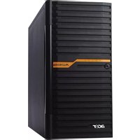


| Product Type | Server |
| Form Factor | Tower |
| Dimensions (H x W x D) | 430 x 200 x 550 mm |
| Weight | Approximately 18 kg |
| Processor | Intel Xeon series (socket LGA 1366) |
| Memory Type | DDR3 ECC Registered |
| Maximum Memory | 192 GB (12 x 16 GB DIMMs) |
| Drive Bays | 8 x 3.5" SATA/SAS hot-swappable |
| RAID Support | Hardware RAID 0/1/5/10 |
| Network Interface | 2 x Gigabit Ethernet (RJ-45) |
| Power Supply | 1 x 500W (redundant optional) |
| Cooling | 4 x hot-swappable system fans |
| Management | Acer Smart Console (IPMI 2.0) |
| Operating Temperature | 10°C to 35°C |
| Operating Humidity | 8% to 80% (non-condensing) |
| Safety Features | Overheat alarm, chassis intrusion detection |
| Maintenance | Clean with soft dry cloth; avoid liquids |
| Repairability | User-replaceable: memory, drives, fans, PSU |
| Included Accessories | Power cable, quick start guide, driver DVD |
Frequently Asked Questions - Altos G540 M2 ACER
User questions about Altos G540 M2 ACER
0 question about this device. Answer the ones you know or ask your own.
Ask a new question about this device
Download the instructions for your Server in PDF format for free! Find your manual Altos G540 M2 - ACER and take your electronic device back in hand. On this page are published all the documents necessary for the use of your device. Altos G540 M2 by ACER.
USER MANUAL Altos G540 M2 ACER
Acer Altos G540 M2 Series
User's Guide
Copyright © 2009 Acer Incorporated All Rights Reserved.
Acer Altos G540 M2 Series User's Guide
Changes may be made periodically to the information in this publication without obligation to notify any person of such revision or changes. Such changes will be incorporated in new editions of this manual or supplementary documents and publications. This company makes no representations or warranties, either expressed or implied, with respect to the contents hereof and specifically disclaims the implied warranties of merchantability or fitness for a particular purpose.
Record the model number, serial number, purchase date, and place of purchase information in the space provided below. The serial number and model number are recorded on the label affixed to the unit. All correspondence concerning the unit should include these information.
No part of this publication may be reproduced, stored in a retrieval system, or transmitted, in any form or by any means, electronic, mechanical, photocopy, recording, or otherwise, without the prior written permission of Acer Incorporated.
Acer Altos G540 M2 Series
Model Name : G540 M2
Part Number: MU.R3500.001
Purchase Date:
Place of Purchase:
Acer and the Acer logo are registered trademarks of Acer Inc. Other company's product names or trademarks are used herein for identification purposes only and belong to their respective companies.
Notices
FCC notice
Class A devices do not have an FCC logo or FCC IDE on the label. Class B devices have an FCC logo or FCC IDE on the label. Once the class of the device is determined, refer to the following corresponding statement.
Class A equipment
This device has been tested and found to comply with the limits for a Class A digital device pursuant to Part 15 of the FCC Rules. These limits are designed to provide reasonable protection against harmful interference when the equipment is operated in a commercial environment. This equipment generates, uses, and can radiate radio frequency energy, and if not installed and used in accordance with the instructions, may cause harmful interference to radio communications. Operation of this equipment in a residential area is likely to cause harmful interference, in which case the user will be required to correct the interference at personal expense.
Notice: Shielded cables
All connections to other computing devices must be made using shielded cables to maintain compliance with FCC regulations.
Notice: Peripheral devices
Only peripherals (input/output devices, terminals, printers, etc.) certified to comply with the Class A limits may be attached to this equipment. Operation with noncertified peripherals is likely to result in interference to radio and TV reception.

Caution: Changes or modifications not expressly approved by the manufacturer could void the user's authority, which is granted by the Federal Communications Commission, to operate this server.
Use conditions
This part complies with Part 15 of the FCC Rules. Operation is subject to the following two conditions: (1) this device may not cause harmful interference, and (2) this device must accept any interference received, including interference that may cause undesired operation.
Notice: Canadian users
This Class A digital apparatus meets all requirements of the Canadian interference-Causing Equipment Regulations.
Laser compliance statement
The CD-ROM drive in this server is a laser product. The CD-ROM drive's classification label (shown below) is located on the drive.
CLASS 1 LASER PRODUCT
CAUTION: INVISIBLE LASER RADIATION WHEN OPEN. AVOID EXPOSURE TO BEAM.
Important safety instructions
Read these instructions carefully. Save these instructions for future reference.
1 Follow all warnings and instructions marked on the product.
2 Unplug this product from the wall outlet before cleaning. Do not use liquid cleaners or aerosol cleaners. Use a damp cloth for cleaning.
3 Do not use this product near water.
4 Do not place this product on an unstable cart, stand, or table. The product may fall, causing serious damage to the product.
5 Slots and openings on the front and rear side of the chassis are provided for ventilation; to ensure reliable operation of the product and to protect it from overheating, these openings must not be blocked or covered. The openings should never be blocked by placing the product on a bed, sofa, rug, or other similar surface. This product should never be placed near or over a radiator or heat register, or in a built-in installation unless proper ventilation is provided.
6 This product should be operated from the type of power indicated on the marking label. If you are not sure of the type of power available, consult your dealer or local power company.
7 Do not allow anything to rest on the power cord. Do not locate this product where persons will walk on the cord.
8 If an extension cord is used with this product, make sure that the total ampere rating of the equipment plugged into the extension cord does not exceed the extension cord ampere rating. Also, make sure that the total rating of all products plugged into the wall outlet does not exceed the fuse rating.
9 Never push objects of any kind into this product through chassis slots as they may touch dangerous voltage points or short out parts that could result in a fire or electric shock. Never spill liquid of any kind on the product.
10 Do not attempt to service this product yourself, as opening or removing covers may expose you to dangerous voltage points or other risks. Refer all servicing to qualified service personnel.
11 Unplug this product from the wall outlet and refer servicing to qualified service personnel under the following conditions:
a When the power cord or plug is damaged or frayed.
b If liquid has been spilled on the product.
c If the product has been exposed to rain or water.
d If the product does not operate normally when the operating instructions are followed. Adjust only those controls that are covered by the operating instructions since improper adjustment of other controls may result in damage and will often require extensive work by a qualified technician to restore the product to normal condition.
e If the product has been dropped or the chassis has been damaged.
f If the product exhibits a distinct change in performance, indicating a need for service.
12 Replace the battery with the same type as the product's battery we recommend. Use of another battery may present a risk of fire or explosion. Refer battery replacement to a qualified service technician.
13 Warning! Batteries may explode if not handled properly. Do not disassemble or dispose of them in fire. Keep batteries away from children. Promptly dispose used batteries according to regulations applicable to your area.
14 Use only the proper type of power supply cord set (provided in your accessories box) for this unit. It should be a detachable type: UL listed/CSA certified, type SPT-2, rated 7A 125V minimum, VDE approved or its equivalent. Maximum length is 15 feet (4.6 meters).
1 System tour 1
System specifications 3
Performance 3
Mechanical 6
Environmental 6
Hardware options 7
External and internal structure 9
Front bezel 9
Front panel 10
Rear panel 13
Internal components 15
System boards 16
Mainboard 16
Backplane board 21
System LED indicators 24
Front panel LED indicators 24
Hot-plug HDD LED indicator 26
Gigabit LAN port LED indicators 27
2 System setup 29
Setting up the system 31
Pre-installation requirements 31
Connecting peripherals 32
Turning on the system 33
Power-on problems 34
Configuring the system OS 36
Rack mount configuration 37
Turning off the system 38
3 System upgrade 39
Installation precautions 41
ESD precautions 41
Pre-installation instructions 42
Post-installation instructions 42
Opening the server 43
Removing the side panel 43
Removing the front bezel 44
Configuring the hard drive 45
Installing a 3.5"HDD cage 45
Removing a HDD cage 48
Installing a 2.5"HDD cage 50
Removing a HDD cage 53
viii
Installing an additional hard drive 55
Configuring a 5-25 inch storage device 64
Upgrading the processor 70
Upgrading the system memory 78
Installing an expansion card 88
Installing the TPM module 91
Installing the System Fan module 92
Installing a redundant power supply module 94
4 System BIOS 97
BIOS overview 99
Entering BIOS setup 100
BIOS setup primary menus 100
BIOS setup navigation keys 101
Main menu 102
Advanced menu 103
Processor Configuration 104
Advanced Memory Configuration 110
Advanced Chipset Control 112
PCI Configuration 116
SATA Configuration 118
I/O Device Configuration 119
Boot Configuration 120
Thermal and Acoustic Configuration 121
Power 123
Security menu 125
Setting a system password 126
Changing a system password 127
Removing a system password 127
Server menu 128
System Management 129
Console Redirection 130
Event Log Configuration 131
Boot menu 133
Exit menu 134
5 System
troubleshooting 135
Resetting the system 137
Initial system startup problems 138
Initial troubleshooting checklist 139
Hardware diagnostic testing 140
Checking the boot-up status 140
Verifying the condition of the storage devices 141
Confirming loading of the operating system 141
Specific problems and corrective actions 142
Appendix A: Server
management tools 147
Server management overview 149
RAID configuration utilities 150
Onboard SATA RAID Configuration Utility 150
LSI MegaRAID SAS 8708EM2 RAID Configuration Utility153
LSI MegaRAID SAS 8204ELP RAID Configuration Utility154
Appendix B: Rack mount configuration 157
Rack installation information 159
Rack installation precautions 159
System rack installation 161
Vertical mounting hole pattern 162
Installing the system into the rack 163
Appendix C: Altos eXpress Console 171
Using Your Altos eXpress Console 173
Software Installation 175
Prerequisites on remote management PC 175
Installing the Java Tool 175
Installing the UPnP tool 176
Using the UPnP tool to search for an Altos server 177
Altos eXpress Console 179
Accessing the Altos eXpress Console 179
Altos eXpress Console User Interface 181
System Status 182
System Information 183
Server Health 185
Configuration 187
Remote Control 200
Maintenance 203
KVM Remote Console Utility 205
Menu bar 207
Index 211
x
1 System tour
The Acer Altos G540 M2 server is a fully modular dual-processor system featuring the latest in computing technology. It host a range of powerful and flexible features designed to meet the needs of various network environments. From simple networking functions to computing intensive applications, the Altos G540 M2 delivers.
System specifications
This section lists down the impressive computing features of the Altos G540 M2 system.
Performance
Processor
- One or two Intel Xeon TM processor 5500 series
- Up to 2.93 GHz
• 4.80/5.86/6.40 GT/s QPI - 4/8 MB shared cache
• 800/1066/1333 DDR3 memory
- Support for the following Intel technologies: 1
- Turbo Boost Technology
• Hyper-Threading (HT) Technology
• Virtualization Technology - QuickPath Technology up to 6.4 GT/s
- 64 Technology
Chipset
- I n 5520 chipset
Memory
- Twelve DDR3 1333 MHz ECC unbuffered/registered DIMMs (six DIMMs per processor), supporting:
- Six-channel memory bus (three channels per processor)
- 1 to 8 GB (subject to availability) registered DIMMs for up to 96 GB of total system memory, or 1 to 4 GB unbuffered DIMMs for up to 48 GB of total system memory
• Memory mirroring, Lockstep mode, x4/x8 SDDC
PCI interface
- Five PCI Express® and PCI expansion slots
- One PCI Express® 2.0 x16 slot
- Two PCI Express® 2.0 x8 slots (with eight PCI Express® 2.0 lanes)
- One PCI Express® x8 slot (with four PCI Express® lanes)
• One PCI (32-bit / 3.3 V) slot
Video controller
- Embedded graphics controller with 32 MB video memory
Networking
- Integrated dual-port Gigabit Ethernet supporting Intel® I/O Acceleration Technology (IOAT)
- Integrated single-port 10/100 Fast Ethernet for server management and KVM over IP remote management
• Supports boot from iSCSI
Media storage
Two front 5.25" drive bays:
- Up to eight 3.5" or sixteen 2.5" SAS/SATA HDDs in two cages
- Easy-swappable
- Supports hot-swap with optional backplane

Note: 3.5" and 2.5" drives cannot be combined together, either you have to all use the 3.5" drive or all 2.5" drive. Combination of the two different sized drive is not supported.
• DVD-ROM or DVD Writer
- 5.25" tape drive (optional)
I/O ports
- Two PS/2 ports
- Serial port
-
VGA port
-
Six USB 2.0 ports
- Two Gigabit LAN ports (RJ-45)
- Fast Ethernet (RJ-45) port dedicated for BMC for management
Power supply and system fan
- 600 W (85% power efficiency) or 610 W power supply, 110-127 / 200-240V (can be upgraded with second power module for hot-swap and redundancy)
- One system fan (can be upgraded with second system fan for redundancy)
Hardware monitoring and server management
- Power status LED
- HDD access LED
• LAN activity LED - System Status LED
- System ID LED/Button
- Chassis intrusion alert
- Lockable door
- IPMI 2.0
- TPM v1.2
- Acer EasyBUILD™v9.0
- Acer Server Manager (ASM)
• Built-in Altos eXpress Console for server management and KVM over IP remote management
Operating system
- Microsoft® Windows® Server 2008 Standard and Enterprise Edition (x86)
-
Microsoft® Windows® Server 2008 Standard and Enterprise Edition (EM64T)
-
Microsoft® Windows® Server 2003 Standard and Enterprise Edition (x86)
- Microsoft® Windows® Server 2003 Standard and Enterprise Edition (EM64T)
- Red Hat® Enterprise Linux 5.0 (x86)
- Red Hat® Enterprise Linux 5.0 (EM64T)
- Novell® SuSE® Linux Enterprise Server 10 (x86)
- Novell® SuSE® Linux Enterprise Server 10 (EM64T)
- VMware ESX4i and VMware ESX4.0
- Novell® NetWare® 6.5
Mechanical
- Chassis
- Tower
- 5U rack-mountable
- Dimensions
- Tower - 5U rack-mountable - Dimensions
- Height: 432 mm (17 in)
- Width: 210 mm (8.27 in)
- Depth: 650 mm (25.6 in)
- Height: 432 mm (17 in) - Width: 210 mm (8.27 in) - Depth: 650 mm (25.6 in)
Environmental
- Temperature
- Operating: +0° to +35°C with the maximum rate of change not to exceed 10° per hour.
Hardware options

Note: To purchase the any of the following hardware options, contact your local Acer representative.
- Intel® Xeon® processor 5500 series:
- 2.66 – 2.93 GHz with 8 MB shared cache, 6.40 GT/s QPI
- 2.26 – 2.53 GHz with 8 MB shared cache, 5.86 GT/s QPI
- 1.86 – 2.13 GHz with 4 MB shared cache, 4.80 GT/s QPI
• 1.86 GHz with 4 MB shared cache, 4.80 GT/s QPI
• Memory
- Registered DDR3 1333 MHz ECC DIMMs: 1/2/4/8 GB
- Unbuffered DDR3 1333 MHz ECC DIMMs: 1/2/4 GB
- HDD:
• 2.5" SAS (10,000 RPM) HDD: 73/146/300 GB
• 2.5" SAS (15,000 RPM) HDD: 36/73/146 GB
• 2.5" SATA 3 Gb/s HDD: 250/320/500 GB
• 3.5" SAS (15,000 RPM) HDD: 147/300/450 GB
• 3.5" SATA 3 Gb/s HDD: 320/500/640 GB, 1/1.5 TB
- Daughter cards/modules:
- TPM module
- Add-on cards:
- ASC/3S single-channel U320 SCSI HBA (for backup device)
• ASSC/3D dual-port SAS HBA (for backup device)
• ASSC/3Q four-port 3 Gb SAS HBA
• ASSRC/3O eight-port 3 Gb SAS RAID HBA - AFC/4S single-port 4 Gb FC HBA
- AFC/4D dual-port 4 Gb FC HBA
• Gigabit Ethernet server adapter - PCI Express® x16 graphics card
- Storage drives:
• Quantum GoVault Tabletop Dock USB drive
• Quantum GoVault Tabletop Dock external USB drive
- Acer DAT160 80/160 GB USB tape drive
- Acer DAT72 36/72 GB USB tape drive
- Acer LTO-3 SAS tape drive
• DVD-RW or DVD Writer
- Hot-swappable, redundant power supply module
- 610 W redundant power supply module
- 600 W redundant power supply module (85% power efficiency)
- Altos rack mount kit
External and internal structure
Front bezel

No. Component
1 Security keylock
This lock secures the bezel door to protect the server unit from unauthorized access.
2 LED indicator panel
For more information on the LED indicators description, go to page 24.
3 Bezel door
Front panel

No. Icon Component Description
| 1 DVD-ROM drive Eject button | Press this button to open the DVD drive tray. |
| 2 DVD-ROM drive mechanical eject hole | When the DVD drive tray get stucked, insert a paperclip to this hole to manually eject the tray. |
| 3 DVD-ROM drive Disk drive for reading | CD, VCD, and DVD contents. |
| 4 DVD-ROM drive activity indicator | When the LED indicator is lit, there is an ongoing DVD drive activity. |
| 5 5.25-inch drive bay Allows installation of additional storage devices. Go to page 4 for a list of supported devices. | |
No. Icon Component Description
| 6 Power indicator Indicates the system power status(green). | |
| 7 HDD activityindicator | Indicates the status of a system hard drive (green/amber). |
| 8 Status/fault indicator Indicates the status of the system operations (green/amber). | |
| 9 LAN port 1 statusindicators | Indicate the system network 1 connection status. |
| 10 LAN port 2 statusindicators | Indicate the system network 2 connection status. |
| 11 Hot-plug HDDactivity indicator | Indicates the activity of a hot-plug HDD installed in the system (green /amber). |
| 12 Hot-plug HDDstatus indicator | Indicates the status of the hot-plug HDD installed in the system (green/amber). |
| 13 Hot-plug HDDlocking mechanism | Locking mechanism to secure the Hot-plug HDD. |
| 14 HDD carrier Supports four hot-plug oreasy-swap SAS or SATA2 HDDs. | |
| 15 HDD cage bay Supports an optional HDD cage(hot-plug or easy-swap). | |
| 16 HDD bay covers Covers for the HDD bays. | |
| 17 Lock Lock for preventing the systemfrom unauthorized access. | |
| 18 USB 2.0 ports Connects to USB devices. | |
| 19 Power button Press to turn the server on/off, or toput it in standby mode. | |
No. Icon Component Description
20 NMI switch If the system crashes or stops
normal operation, press the NMI switch to mechanically force the server to issue a non-maskable interrupt. This will perform a memory dump-writing the contents of the server's CPU registers and RAM to a network server or to diskettes. This memory dump can later be analyzed to determine the cause of the problem.
21 Unit identification
(UID) switch/indicator
Press the ID button to turn on the ID LED indicator. This identifies a particular unit within a server group during servicing or maintenance procedures.
Rear panel

No. Icon Component Description
| 1 Power supply | module release latch | Push down the latch to disengage the module from the chassis. |
| 2 Power supply | module cord socket | Connect the system power cord here. |
3 Power supply  | module fault indicator | Indicates the occurrence of a fault condition in the power supply module. (green/amber) |
4 Power supply  | module status indicator | Indicates the status of the power supply module. (green) |
| 5 | M supply module | Provides the system's main power supply. |
No. Icon Component Description
| 6 PS/2 mouse port | Connects to a PS/2 mouse. | |
7 PS/2 ke  board port board port | Connects to a PS/2 keyboard. | |
8 Monit  port Connects to monitors. port Connects to monitors. | ||
| 9 Serial port Connects to serial devices. | ||
| 10 USB 2.0 ports Connects to USB devices. | ||
11 Unit  | identification (UID) switch/ indicator | Press to mark a particular server unit within a server group (when rack-mounted) for purpose of identification during servicing or maintenance procedures. (blue) |
12 Management  | LAN port | Fast Ethernet (RJ-45) port dedicated for BMC management. |
13 Giga  AM ports 1/2 AM ports 1/2 | Connects to an Internet or intranet network. | |
| 14 PCI slot covers Protects the vacant expansion slots. | ||
| 15 System fan Regulates the system airflow. | ||
| 16 Lid switch Sent out warning alerts when the lid is opened or compromised. | ||
| 17 Redundant | power supply module bay | Accommodates an optional hot-swap redundant power supply module. |
Internal components

No. Component
1 Redundant power supply module bay
2 Air duct
3 Heat sink fan (HSF) assemblies
4 Sliders for the 5.25-inch devices
5 Release sliders for the HDD cages
6 Mainboard
7 P C I s I o t I o c k
8 System fan
Users have the option to purchase a redundant system fan unit.
System boards
Mainboard

No. Code Description
1 KB PS/2 Keyboard port
2 MS PS/2 Mouse port
3 VGA VGA D-sub port
No. Code Description
| 4 COM COM A serial port | ||
| 5 USB USB ports | ||
| 6 ID_SW ID switch | ||
| 7 MNGT_NIC Management LAN port | ||
| 8 GBE1 Gigabit LAN port 1 | ||
| 9 GBE2 Gigabit LAN port 2 | ||
| 10 FAN_SYS5 Redundant fan 1 connector (default) | ||
| 11 FAN_SYS6 Redundant fan 2 connector | ||
| 12 12V_AUX2 8-pin Power connector for Processor 2 | ||
| 13 DIMMF1/ DIMMF2 | DDR3 memory slot 1/2 (Channel F) for Processor 2 | |
| 14 DIMME1/ DIMME2 | DDR3 memory slot 1/2 (Channel E) for Processor 2 | |
| 15 DIMMD1/ DIMMD2 | DDR3 memory slot 1/2 (Channel D) for Processor 2 | |
| 16 ATX 24-pin ATX Power connector | ||
| 17 CPU1 Processor 1 Socket | ||
| 18 FAN_CPU1 FAN connector for Processor 1 | ||
| 19 12V_AUX1 8-pin Power connector for Processor 1 | ||
| 20 DIMMA1/ DIMMA2 | DDR3 memory slot 1/2 (Channel A) for Processor 1 | |
| 21 DIMMB1/ DIMMB2 | DDR3 memory slot 1/2 (Channel B) for Processor 1 | |
| 22 DIMMC1/ DIMMC2 | DDR3 memory slot 1/2 (Channel C) for Processor 1 | |
| 23 USB_A USB Type A connector | ||
No. Code Description
| 24 U82 Intel® 5520 (North Bridge) |
| 25 USB1 USB connector for internal USB (Tape Device) |
| 26 U60 Intel ICH 10R (South Bridge) |
| 27 TPM TPM connector |
| 28 J3 SMBus connector for backplane board 2 |
| 29 J2 SMBus connector for backplane board 1 |
| 30 USB_3 USB connector for SSD |
| 31 PSMI1 PSMI connector |
| 32 SATA0 SATA connector 0 |
| 33 SATA1 SATA connector 1 |
| 34 SGPIO_JP2 SGPIO connector for backplane board 2 |
| 35 SATA2 SATA connector 2 |
| 36 SGPIO_JP1 SGPIO connector for backplane board 1 |
| 37 SATA3 SATA connector 3 |
| 38 SATA4 SATA connector 4 |
| 39 CLR_CMOS Clear CMOS jumper |
You may clear the CMOS data to its default values by this jumper.
Default value doesn't include the "Shunter" to prevent from improper use of this jumper. To clear CMOS, temporarily short 2-3 pin.
1

1-2 close: Normal operation (Default setting)
1

2-3 close: Clear CMOS
No. Code Description
40 SATA5 SATA connector 5 for SATA ODD
41 F_PANEL Front panel connector
42 J1 BMC firmware upgrade connector
43 IPMB1 3-pin IPMB connector
44 BAT CMOS Battery
45 IPMB2 4-pin IPMB connector
46 USB2 USB connector for front USB ports
47 CASE_OPEN Chassis Intrusion connector
48 COMB COM B serial port connector
49 PCI5 PCI slot 5 (32bit/33MHz/3.3V)
50 BIOS_RVCR BIOS Recovery Jumper
1
1-2 close: Normal operation. (Default setting)
1
2-3 close: Enable BIOS Recovery function
51 PCI-E4 PCI-E x8 slot 4 (Gen1, x4 throughput)
52 PCI-E3 PCI-E x8 slot 3 (Gen2)
53 U5 BMC
54 PCI-E2 PCI-E x8 slot 2 (Gen2)
55 U188 Hardware monitor controller
56 U6 Gigabit Ethernet Network Controller
57 PCI-E1 PCI-E x16 slot 1 (Gen2)
58 FAN_CPU2 FAN connector for Processor 2
59 U24 10/100 Fast Ethernet PHY
No. Code Description
60 CPU2 Processor 2 Socket
Backplane board
The backplane board attached to rear of the hot-plug HDD cage is what differentiate it from the easy-swap HDD cage model.
3.5" Backplane Board

No. Code Description
1 J14 Close 1-2: Two LED indication (default)
Close 2-3: Single LED indication (backward support)
2 J16 Backplane address setting:
3 J15
| Jumper | Backplane 1 | Backplane 2 |
| J15 | Close 2-3 | Close 2-3 |
| J16 | Close 1-2 | Close 2-3 |
4 J3 SMBUS connector for backplane cascade
5 J2 SMBUS connector to main board (J2)
No. Code Description
6 J1 SMBUS connector to RAID card
7 SAS/CON SAS 8484 32-pin connector
8 J17 Close 1-2: default
Close 2-3: backward support
9 CN1/X1 Power connector (4-pin)
10 CN1/X2 Power connector (4-pin)
2.5" Backplane Board

No. Code Description
1 J27 Close 1-2: Two LED indication (default)
Close 2-3: Single LED indication (backward support)
2 J2 SMBUS connector to main board (J2)
No. Code Description
| 3 J28 Backplane address setting: | ||||
| Jumper | Backplane 1 | Backplane 2 | ||
| 4 | J29 | J28 | Close 2-3 | Close 1-2 |
| 5 | J30 | J29 | Close 1-2 | Close 2-3 |
| J30 | Close 2-3 | Close 1-2 | ||
| 6 | J31 | J31 | Close 2-3 | Close 1-2 |
| 7 CN2/X1 Power connector (4-pin) | ||||
| 8 J3 SMBUS connector for backplane cascade | ||||
| 9 CN1/X1 Power connector (4-pin) | ||||
| 10 J1 SMBUS connector to RAID card | ||||
| 11 SAS/CON1 SAS 8484 32-pin connector (port 0 ~ 3) | ||||
| 12 SAS/CON2 SAS 8484 32-pin connector (port 4 ~ 7) | ||||
System LED indicators
This section discusses the different LED indicators located on the:
- Front panel
• Hot-plug HDD carrier
• LAN port
Knowing what each LED indicator signifies can aid in problem diagnosis and troubleshooting.
Front panel LED indicators
The six LED indicators mounted on the front bezel. These indicators remain visible even when the bezel door is closed.
| Indicator | Color | State | Representative Status |
| Power Green ON | S0: Power ON | ||
| Green Blink | (1Hz with at 50% duty cycle) | S1: Sleep | |
| N/A OFF S4 | |||
| N/A OFF S5 | |||
| HDD activity Green | Blink HDD | Access | |
| N/A OFF No | access and No HDD | fault | |
| System Status Green ON System Ready / No | Alarm | ||
Hot-plug HDD LED indicator
A drive activity LED indicator is mounted on the hot-plug HDD carrier. The table below lists the possible drive states.
| Status | i | |
| HDD Present Steady ON OFF | ||
| HDD Access Blink OFF | ||
| HDD Failure OFF Steady ON | ||
| HDD Removed OFF Steady ON | ||
| HDD Insert and rebuilding | Steady ON Blink | |
| HDD Locate Blink Blink | ||
Gigabit LAN port LED indicators

| LED Indicator | LED # | LED Color | LED State | NIC State |
| Network speed (left) | 1, 3, 5 Amber On 1000 Mbps link network access | |||
| Green On 100 Mbps link network access | ||||
| Off 10 Mbps link network access | ||||
| Network connection (right) | 2, 4, 6 Green On Active network link | |||
| Green Blinking Transmit/Receive activity | ||||
2 System setup
This chapter gives you instructions on how to prepare the system for operation. Procedures for connecting peripherals are also explained.
Setting up the system
Pre-installation requirements
Selecting a site
Before unpacking and installing the system, select a suitable site for the system for maximum efficiency. Consider the following factors when choosing a site for the system:
- Near a grounded power outlet
- Clean and dust-free
- Stable surface free from vibration
- Well-ventilated and away from sources of heat
- Secluded from electromagnetic fields produced by electrical devices such as air conditioners, radio and TV transmitters, etc.
Checking the package contents
Check the following items from the package:
- Acer Altos G540 M2 system
• A c e r TM DVDaPack y B U I L D - Acer Altos G540 M2 accessory box
- System key s
If any of the above items are damaged or missing, contact your dealer immediately.
Save the boxes and packing materials for future use.
Connecting peripherals
The color-coded I/O port panel on the system rear accepts a variety of compatible peripherals. Refer to the figure below for specific connection instructions for each port.


Note: Consult the operating system manual for information on how to configure the network setup.

Caution: Do not route the power cord where it will walked on or pinched by items placed against it. The server is designed to be electrically grounded (earthed). To ensure proper operation, plug the power cord into a properly grounded AC outlet only.
Turning on the system
After making sure that you have properly set up the system, applied power, and connected all the necessary peripherals, you can now power on the system. Follow the procedure below.
1 Unlock and open the bezel door.

2 Press the power button.

The system starts up and displays a welcome message on the monitor. After that, a series of power-on self-test (POST) messages appears. The POST messages indicate if the system is running well or not.

Note: If the system does not turn on or boot after pressing the power button, go to the next section for the possible causes of the boot failure.
Aside from the POST messages, you can determine if the system is in good condition by checking if the following occurred.
- The power status indicator on the front panel lights up green.
- The Num Lock, Caps Lock, and Scroll Lock indicators on the keyboard light up.
Power-on problems
If the system fails to boot after you have applied power, check the following factors that might have caused the boot failure.
- The external power cord may be loosely connected.
Check the power cord connection from the power outlet to the power cord socket on the rear panel. Make sure that the cord is
properly connected to the power outlet and to the power cord socket.
- No power comes from the grounded power outlet.
Have an electrician check your power outlet.
- Loose or improperly connected internal power cables.
Check the internal cable connections. If you are not confident to perform this step, ask a qualified technician to assist you.

Warning! Make sure all power cords are disconnected from the electrical outlet before performing this task.

Note: If you have gone through the preceding actions and the system still fails to boot, ask your dealer or a qualified technician for assistance.
Configuring the system OS
The Altos G540 M2 comes with Acer EasyBUILD that allows users to conveniently install the preferred operating system. To start using EasyBUILD, follow the steps below.
1 Locate the EasyBUILD DVD included in the system package.
2 With the system turned on, press the DVD-ROM drive Eject button.
3 When the disc tray slides open, insert the EasyBUILD DVD with the label side of the disc facing upward.

Note: When handling the disc, hold it by the edges to avoid smudges or fingerprints.
4 Gently press the disc down to make sure that it is properly inserted.

Caution: While pressing the disc, be careful not to bend the disc tray. Make sure that the disc is properly inserted before closing the disc tray. Improper insertion may damage both the disc and the DVD-ROM drive.
5 Press the drive Eject button again to close the disc tray.
6 The Acer EasyBUILD sequence begins. Follow all onscreen instructions.
For more information, refer to the EasyBUILD Installation guide.

Note: EasyBUILD only supports the Microsoft and Red Hat Linux operating systems. The Windows or Red Hat installation disc(s) is required to install the OS.
Rack mount configuration
The Altos G540 M2 server is a dual-platform system that can be set up in both tower and rack-mount configurations. A rack mount kit is available for customers who prefer to mount the server in a system rack. To purchase a rack mount kit, contact your local Acer representative or order directly from http://www.acer.com/.
The figure below shows the Altos G540 M2 server in a rack-mount position.

For instructions on tower-to-rack configuration, refer to "Appendix B: Rack mount configuration" on page 157.
Turning off the system
There are two ways to turn off the server—via software or via hardware. The software procedure below applies to a system running on a Windows OS. For other NOS shutdown procedures, refer to the related user documentation.
To turn off the system via software:
1 Press Ctrl+Alt+Delete on the attached keyboard or click the Start on the Windows taskbar.
2 Select Shut Down.
3 Select Shut down from the drop-down menu, then click OK.
To turn off the system via hardware:
If you cannot shut down the server via software, press the power button for at least four seconds. Quickly pressing the button may put the server in a Suspend mode only.
3 System upgrade
This chapter discusses the precautionary measures and installation procedures you need to know when upgrading the system.
Installation precautions
Before you install any server component, it is recommended that you read the following sections first. These sections contain important ESD precautions along with pre-installation and post-installation procedures.
ESD precautions
Electrostatic discharge (ESD) can damage static-sensitive hardware components, such as the processor, disk drives, and the system boards. Always observe the following precautions before you install a server component:
- Do not remove a component from its protective packaging until you are ready to install it.
- Do not touch the component pins, leads, or circuitry.
- Components with a Printed Circuit Board (PCB) assembly should always be laid with the assembly-side down.
- Wear a wrist grounding strap and attach it to a metal part of the server before handling components. If a wrist strap is not available, maintain contact with the server throughout any procedure requiring ESD protection.
- Keep the work area free of nonconductive materials, such as ordinary plastic assembly aids and foam packing.
Pre-installation instructions
Perform the steps below before you open the server or before your remove or replace any component.

Warning! Failure to properly turn off the server before you start perform any hardware configuration may cause serious damage and bodily harm. Do not attempt the procedures described in the following sections unless you are a qualified service technician.
1 Turn off the server and all connected peripherals.
2 Unplug all power cables from their outlets.
3 Disconnect all telecommunication cables from their ports.
4 Place the server on a flat, stable surface.
5 Open the server according to the instructions on page 43.
6 Follow the ESD precautions described in the previous section when handling a server component.
Post-installation instructions
Perform the steps below after installing a server component.
1 See to it that all components are installed according to the described step-by-step instructions.
2 Reinstall any expansion board(s), peripheral(s), bracket (s) and system cable(s) that have previously been removed.
3 Reinstall the side panel.
4 Reconnect the power, peripheral, and telecommunication cables.
5 Turn on the system.
Opening the server

Caution: Before you proceed, make sure that you have turned off the system and all peripherals connected to it. Read the "Pre-installation instructions" section on page 42.
You need to open the server before you can install upgrade components. The front bezel and (left) side panel are removable to allow access to the server's internal components. Refer to the following sections for instructions.
Removing the side panel
1 Perform the pre-installation instructions described on page 41.
2 Unlock the security keylock.
3 Remove the two thumb screws on the back panel.
4 Slide the side panel toward the rear of the chassis to disengage it.

Removing the front bezel
1 Remove the side panel.
Refer to the previous section for instructions.
2 Remove the front bezel.
(1) Release the bezel door retention tabs from the chassis interior.
(2) Firmly bump the bezel as shown to loosen it.
(3) Pull the bezel away from the chassis.

Configuring the hard drive
The two HDD cage bays of the Altos G540 M2 accommodates both hot-plug and easy-swap HDD cage models. The main difference between these two cage models is the presence of a backplane board on the rear side of the hot-plug HDD cage. Both cage models support up to four SATA2 or SAS hard disk drives.
The system ships out with only a single HDD cage occupying the top cage bay. You have the option to purchase an extra HDD cage to provide the system with additional storage capacity and scalability. Contact your local Acer representative for more information.
The system supports 3.5" or 2.5" HDDs. It cannot support both at once. If the systems ships with the 3.5" HDDs, then any additional HDDs should also be the same size. That goes the same for the 2.5" HDDs.

Caution: You cannot mix 3.5" HDDs with 2.5" HDDs on the same system.

Note: The HDD cage comes with HDD dummy covers. You need to purchase a blank HDD carrier to install a hard drive.
Installing a 3.5" HDD cage
1 Perform the pre-installation instructions described on page 41.
2 Remove the plastic cover by releasing it from the latches.

3 Remove the HDD cage bay metal cover from the front chassis.
(1) Remove the screws securing the cover.
(2) Detach the cover from chassis.
Store this cover for future reinstallation.

4 Install the HDD cage.
(1) Slide the cage into the lower bay with the HDD carriers facing front.
Then lock the cage by sliding the locker down as shown.

If you have installed a hot-plug HDD cage, proceed to next step for related drive cable connections.
Drive cable connections for an easy-swap HDD can be found on page page 58.
(2) Connect the following cables to the hot-plug HDD cage backplane board.
(1) Connect the hard drive power cables to the CN1 and CN2 connectors of the backplane board.
(2) Connect the SAS/SATA2 cable to the SAS/CON connector of the backplane board.

5 Observe the post-installation instructions described on page 42.
For instructions on how to install a hard drive in an easy-swap HDD cage, go to page 57.
For instructions on how to install a hard drive in a hot-plug HDD cage, go to page 55.
Removing a HDD cage
1 Perform the pre-installation instructions described on page 41.
2 Prepare the HDD cage for removal.
- For a hot-plug HDD cage, disconnect the data and power cables from the backplane board, then remove all HDDs from the cage.
- For an easy-swap HDD cage, disconnect the data and power cables from their HDD connectors, then remove all HDDs from the cage.
3 Remove the HDD cage.
(1) Move the release slider all the way up to unlock the hot-plug HDD cage.
(2) Remove the cage from the HDD bay.

4 Observe the post-installation instructions described on page 42.
Installing a 2.5" HDD cage
1 Perform the pre-installation instructions described on page 41.
2 Remove the 2 plastic covers by releasing it from the latches.

3 Place the top plastic cover as shown.

4 Remove the HDD cage bay metal cover from the front chassis.
(1) Remove the screws securing the cover.
(2) Detach the cover from chassis.
Store this cover for future reinstallation.

5 Install the HDD cage.
(1) Slide the cage into the lower bay with the HDD carriers facing front.
Then lock the cage by sliding the locker down as shown.

If you have installed a hot-plug HDD cage, proceed to next step for related drive cable connections.
Drive cable connections for an easy-swap HDD can be found on page page 58.
(2) Connect the following cables to the hot-plug HDD cage backplane board.
(1) Connect the hard drive power cables to the CN1 and CN2 connectors of the backplane board.
(2) Connect the SAS/SATA2 cable to the SAS/CON connector of the backplane board.

6 Observe the post-installation instructions described on page 42.
For instructions on how to install a hard drive in an easy-swap HDD cage, go to page 57.
For instructions on how to install a hard drive in a hot-plug HDD cage, go to page 55.
Removing a HDD cage
1 Perform the pre-installation instructions described on page 41.
2 Prepare the HDD cage for removal.
- For a hot-plug HDD cage, disconnect the data and power cables from the backplane board, then remove all HDDs from the cage.
- For an easy-swap HDD cage, disconnect the data and power cables from their HDD connectors, then remove all HDDs from the cage.
3 Remove the HDD cage.
(1) Move the release slider all the way up to unlock the hot-plug HDD cage.
(2) Remove the cage from the HDD bay.

4 Observe the post-installation instructions described on page 42.
Installing an additional hard drive
The Altos G540 M2 HDD cage models supports both SATA2 and SAS hard drives in different capacities.

Note: You cannot mix the 3.5" HDD with the 2.5" HDD on the system.
To install 3.5" a hot-plug hard drive:
1 If necessary, unlock the front bezel, then pull it open.
2 Remove the HDD dummy cover from the cage.

3 Prepare the blank HDD carrier for installation.
(1) Remove the four screws that secures the blank frame. You will use these screws to secure the hard disk later.
(2) Detach the plastic frame from the HDD carrier.

4 Align the new hard disk with the HDD carrier, then secure it with the four screws you removed in step 3-1.

5 Install the new hard drive into the cage.
(1) Slide the drive into the cage with the carrier handle still extended.
(2) Make sure that the drive is properly inserted before pushing the handle back until it clicks into place.

6 Set up the new hard drive's RAID configuration.
For related instructions, go to the "RAID configuration utilities" section on page 150.
To install 2.5" a hot-plug hard drive:
1 If necessary, unlock the front bezel, then pull it open.
2 Remove the HDD dummy cover from the cage.

3 Prepare the blank HDD carrier for installation.
(1) Remove the four screws that secures the blank frame. You will use these screws to secure the hard disk later.
(2) Detach the plastic frame from the HDD carrier.

4 Align the new hard disk with the HDD carrier, then secure it with the four screws you removed in step 3-1.

5 Install the new hard drive into the cage.
(1) Slide the drive into the cage with the carrier handle still extended.
(2) Make sure that the drive is properly inserted before pushing the handle back until it clicks into place.

6 Set up the new hard drive's RAID configuration.
For related instructions, go to the "RAID configuration utilities" section on page 150.
Configuring a 5-25 inch storage device
The three 5.25-inch device bays support a variety of storage devices for additional storage capacity and scalability. Go to page 4 for a list of supported storage devices.
By default, the system ships with a DVD-ROM drive installed on the topmost device bay. You can choose to replace these default drives, or you can install a new storage device on the second device bay.
To install an optional storage device:
1 Perform the pre-installation instructions described on page 41.
2 Remove the two screws that secure the cover of the empty 5.25-inch drive bay (1), then detach the cover (2).
Keep this cover for future reinstallation.

3 Install the new 5.25-inch storage device.
The instructions given below apply to a regular 5.25-inch storage device.

Note: There is an extra bracing lock on the side of the 5.25-in drive cage for installing another 5.25-inch device.
4 Install the bracing lock tab as shown.

(1) Slowly slide the drive into the drive bay.
(2) Connect the power and SATA cables to the new 5.25-inch drive.

5 Observe the post-installation instructions described on page 42.
To remove a defective storage device:
1 Perform the pre-installation instructions described on page 41.
2 Remove the cables as shown (1 and 2). Press on both side of the bracing lock tab (3) and pull out the drive from the drive bay (4).

3 Remove the bracing lock tab from the old DVD drive.

4 Install the bracing lock tab on the new DVD device as shown.

(1) Slowly slide the drive into the drive bay.
(2) Connect the power and SATA cables to the new 5.25-inch drive.

Upgrading the processor
This section explains the procedures for removing and installing the processor and heat sink fan (HSF) assembly.
Processor configuration guidelines
The mainboard supports up to two Intel® Xeon™ processor 5500 series. You have the option to upgrade the default processor or install a second one for a dual-processor configuration.
Observe the following guidelines when replacing or installing a processor.
- The CPU 1 socket must always be populated. If no processor is installed in this socket, the system will fail to boot.
- Before removing a processor, make sure to back up all important system files.
- When installing a second processor, make sure it has same stepping and frequency specifications as the default processor.
- Handle the processor and the HSF assembly carefully. Damage to either may prevent the system from functioning properly.

Note: A long-nosed screwdriver is needed to remove/install the HSF assembly.
To upgrade the default processor:
1 Perform the pre-installation instructions described on page 41.
2 Lay the server on its side (components showing).
3 Remove the screws securing the HSF air duct assembly. Carefully remove the HSF air duct assembly. Remember to keep the screws in a safe place for later reassembly.

4 Disconnect the processor 1 HSF cable from its mainboard connector and remove the HSF assembly.
(1) Use a long-nosed screwdriver to loosen the four HSF mounting pins.
(2) Once you have loosened all four mounting pins, lift the HSF away from the mainboard.

(3) Lay down the HSF in an upright position—with the thermal patch facing upward. Do not let the thermal patch touch the work surface.
Use an alcohol pad to wipe off the thermal grease from both the HSF assembly and the processor socket retention plate.
5 Remove the default processor.

Warning! The processor becomes very hot when the system is on. Allow it to cool off first before handling.
(1) Release then lift up the load lever.
(2) Open the retention plate to expose the socket body.
(3) Grasp the processor by its edges and lift it out of its socket.

6 Store the old processor inside an anti-static bag.
7 Remove the new processor from its protective packaging.
8 Install the new processor.
(1) Hold the processor by its edges, then insert it in the socket.
Make sure that the alignment tabs on the socket fit the two notch located on the edge of the processor. The pins are keyed in such a way that you cannot install the processor in the wrong orientation without bending the pins.
(2) Close the retention plate.
(3) Engage the load lever back into place.

9 Apply the thermal interface material.
(1) Use an alcohol pad to wipe off the old thermal grease from both the HSF assembly and the processor socket retention plate.
(2) Apply a thin layer of an Acer-approved thermal interface material before installing the HSF.
Make sure that only a very thin layer is applied so that both contact surfaces are still visible.
10 Reinstall the HSF assembly.
(1) Align then insert the HSF on top of the retention plate.
(2) Use a long-nosed screwdriver to tighten the four HSF mounting pins to secure the assembly. Reconnect the HSF cable to its mainboard connector.

Refer to the "Mainboard" section on page 16 for the location of
the HSF connectors.
11 Replace the HSF air duct assembly. Make sure to seat the HSF air duct assembly properly before replacing the screws in place.

12 Observe the post-installation instructions described on page 42.
To install a second processor:
1 Perform steps 1 through 4 of the previous section.
2 Prepare the processor socket 2 for installation.
Refer to steps 5-1 and 5-2 of the previous section.
3 Install the new processor.
Refer to steps 7 and 8 of the previous section.
4 Reinstall the HSF assembly.
(1) Align then insert the HSF on top of the retention plate.
(2) Use a long-nosed screwdriver to tighten the four HSF mounting pins to secure the assembly.

5 Observe the post-installation instructions described on page 42.
Upgrading the system memory
This section explains the procedures for removing and installing a fully-buffered memory module.
Memory Configuration Guideline
Altos G540 M2 has twelve DIMM slots. Each CPU controls six DIMM slots. The DIMM slots support three channel DDR3-1333 registered/unbuffered ECC memory modules. For CPU1, it will be channel A, B &C. For CPU2, it will be channel D,E &F. Each channel has 2 sockets. The farthest socket to CPU is socket 1 (A1,B1,C1,D1,E1,F1 in color BLUE), while the nearest one is socket 2 (A2,B2,C2,D2,E2,F2 in color black). For all memory modes, the socket 1 in each channel should be populated first. If socket 1 is empty, socket 2 can't be used.


Note:
(1) When you are using a single-processor server, you should install the memory module into DIMM A1 to DIMM C2 slots.
(2) The DIMM D1 to DIMM F2 slots are enabled when a second CPU is installed on the mainboard.
For the system to function, DIMM modules must be installed following the slot sequence listed below. DIMM module of the same type, size and manufacturer must be installed in the same colored DIMM slots.
- CPU 1 - Populate DIMM slots A1 first, followed by slots B1, C1, A2, B2, and C2.
- CPU 2 - Populate DIMM slots D1 first, followed by slots E1, F1, D2, E2, and F2.
- To ensure data integrity, use only Acer-approved 240-pin, DDR3 Registered/Unbuffered DIMM ECC modules in 1 GB, 2 GB, 4 GB, or 8 GB capacities.
- Use identical modules—same specification for size, speed, and organization.
Independent Mode:
Singel processor configuration
Observe the population sequence illustrated in the table below when installing a memory module.
| Total Capacity | DIMM A2 | DIMM A1 | DIMM B2 | DIMM B1 | DIMM C2 | DIMM C1 |
| 1GB 1GB | ||||||
| 2GB 1GB 1GB | ||||||
| 3GB 1GB 1GB 1GB | ||||||
| 4GB 1GB 1GB 1GB 1GB | ||||||
| 6GB 1GB 1GB 1GB 1GB 1GB | 1GB | |||||
| 2GB 2GB | ||||||
| 4GB 2GB 2GB | ||||||
| 6GB 2GB 2GB 2GB | ||||||
| 8GB 2GB 2GB 2GB 2GB | ||||||
| 12GB | 2GB 2GB 2GB 2GB 2GB | 2GB 2GB | 2GB | |||
| 4GB 4GB | ||||||
| 8GB 4GB 4GB | ||||||
| 12GB 4GB 4GB | 4GB | |||||
| 16GB 4GB 4GB | 4GB 4GB | |||||
| 24GB 4GB 4GB | 4GB 4GB 4GB | 4GB | ||||
| 8GB* 8GB | ||||||
| 16GB* 8GB 8GB | ||||||
| 24GB* 8GB 8GB | 8GB | |||||
| 32GB* 8GB 8GB | 8GB 8GB | |||||
| 48GB* 8GB 8GB | 8GB 8GB 8GB | 8GB |

Note: *Support depends on 8GB DIMM available
Dual processor configuration
Observe the population sequence illustrated in the table below when installing a memory module.
| Total Capacity | DIMM | |||||||||||
| A1 | A2 | B1 | B2 | C1 | C2 | D1 | D2 | E1 | E2 | F1 | F2 | |
| 2GB | 1 GB | 1 GB | ||||||||||
| 3GB | 1 GB 1 | GB 1 GB | ||||||||||
| 4GB | 1 GB 1 | GB | 1 | GB 1 GB | ||||||||
| 6GB | 1 GB 1 | GB 1 GB | 1 GB | 1 GB | 1 GB | |||||||
| 8GB | 1 GB | 1 GB | 1 GB | 1 GB | 1 GB | 1 GB | 1 GB | 1 GB | ||||
| 9GB | 1 GB | 1 GB | 1 GB | 1 GB | 1 GB | 1 GB | 1 GB | 1 GB | 1 GB | |||
| 12GB | 1 GB | 1 GB | 1 GB | 1 GB | 1 GB | 1 GB | 1 GB | 1 GB | 1 GB | 1 GB | 1 GB | 1 GB |
| 4GB | 2 GB | 2GB | ||||||||||
| 6GB | 2 GB 2 | GB 2 GB | ||||||||||
| 8GB | 2 GB 2 | GB | 2 | GB 2 GB | ||||||||
| 12GB | 2 GB 2 | GB 2 GB | 2 GB | 2 GB | 2 GB | |||||||
| 16GB | 2 GB | 2 GB | 2 GB | 2 GB | 2 GB | 2 GB | 2 GB | 2 GB | ||||
| 18GB 2 GB 2 | GB 2 GB | 2 GB 2 | GB 2 GB | B 2 GB | 2 GB 2 GB | |||||||
| 24GB 2 GB 2 | GB 2 GB | 2 GB 2 | GB 2 GB | B 2 GB | 2 GB 2 GB | 2 GB 2 GB | 2 GB 2 GB | |||||
| 8GB 4 GB 4 GB | ||||||||||||
| 12GB 4 GB 4 | GB 4 GB | |||||||||||
| 16GB 4 GB 4 | GB | 4 | GB 4 GB | |||||||||
| 24GB 4 GB 4 | GB 4 GB | 4 GB | 4 GB | 4 GB | ||||||||
| 32GB 4 GB 4 | GB 4 GB | 4 GB | 4 GB | 4 GB | 4 GB | 4 GB | ||||||
| 36GB 4 GB 4 | GB 4 GB | 4 GB 4 | GB 4 GB | B 4 GB | 4 GB 4 GB | |||||||
| 48GB 4 GB 4 | GB 4 GB | 4 GB 4 | GB 4 GB | B 4 GB | 4 GB 4 GB | 4 GB 4 GB | 4 GB 4 GB | |||||
| 16GB* | 8 GB 8 | GB | ||||||||||
| 24GB* | 8 GB 8 | GB 8 GB | ||||||||||
| 32GB* | 8 GB 8 | GB | 8 | GB 8 GB | ||||||||
| 48GB* | 8 GB 8 | GB 8 GB | 8 GB | 8 GB | 8 GB | |||||||
| 64GB* | 8 GB 8 | GB 8 GB | 8 GB | 8 GB | 8 GB | 8 GB | 8 GB | |||||
| 72GB* | 8 GB 8 | GB 8 GB | 8 GB | 8 GB | 8 GB | 8 GB | 8 GB | |||||
| 96GB* | 8 GB 8 | GB 8 GB | 8 GB | 8 GB | 8 GB | 8 GB | 8 GB | 8 GB | 8 GB | 8 GB | ||

Note: *Support depends on 8GB DIMM available
Mirroring or Lockstep mode :
- Mirroring mode & Lockstep mode need the channel A & channel B with identical DIMMs. A1 and B1 should be the same type, size and manufacturer. A2 and B2 memory should be the same type, size and manufacturer.
- Channel C has no function in this mode.
- Same rule is applied to the CPU2 memory channel D,E,F.
- For mirroring mode, the memory contain a primary image and a copy of the primary image. Therefore, the effective size of memory is reduced by at least one-half.
Single Processor Configuration
| Total Capacity | DIMM A2 | DIMM A1 | DIMM B2 | DIMM B1 | DIMM C2 | DIMM C1 |
| 2GB 1GB 1GB | ||||||
| 4GB 1GB 1GB 1GB 1GB | ||||||
| 4GB 2GB 2GB | ||||||
| 8GB 2GB 2GB 2GB 2GB | ||||||
| 8GB 4GB 4GB | ||||||
| 16GB 4GB 4GB 4GB 4GB | ||||||
| 16GB* 8GB 8GB | ||||||
| 32GB* 8GB 8GB 8GB 8GB | ||||||

Note: *Support depends on 8GB DIMM available
Dual Processor Configuration
| Total Capacity | DIMM | |||||||||||
| A2 | A1 | B2 | B1 | C2 | C1 | D2 | D1 | E2 | E1 | F2 | F1 | |
| 2GB 1GB 1GB | ||||||||||||
| 4GB 1GB 1GB 1GB 1GB | ||||||||||||
| 6GB 1GB 1GB 1GB 1GB 1GB 1GB | ||||||||||||
| 8GB 1GB 1GB 1GB 1GB 1GB 1GB 1GB | ||||||||||||
| 4GB 2GB 2GB | ||||||||||||
| 8GB 2GB 2GB 2GB 2GB | ||||||||||||
| 12GB | 2GB 2GB 2GB 2GB 2GB 2GB | |||||||||||
| 16GB | 2GB 2GB 2GB 2GB 2GB 2GB 2GB 2GB | |||||||||||
| 8GB 4GB 4GB | ||||||||||||
| 16GB | 4GB 4GB 4GB 4GB 4GB | |||||||||||
| 24GB | 4GB 4GB 4GB 4GB 4GB 4GB | |||||||||||
| 32GB | 4GB 4GB 4GB 4GB 4GB 4GB 4GB 4GB | |||||||||||
| 16GB* | 8GB 8GB | |||||||||||
| 32GB* | 8GB 8GB 8GB 8GB | |||||||||||
| 48GB* | 8GB 8GB 8GB 8GB 8GB 8GB | |||||||||||
| 64GB* | 8GB 8GB 8GB 8GB 8GB 8GB 8GB 8GB | |||||||||||

Note: *Support depends on 8GB DIMM available
To remove a DDR3 Registered/Unbuffered DIMM:

Important: Before removing a DDR3 Registered/Unbuffered DIMM, make sure to back up all important system files. Also, note that DDR3 Registered/Unbuffered DIMMs should be removed in pairs.
1 Perform the pre-installation instructions described on page 41.
2 Lay the server on its side (components showing).
3 Remove the HSF air duct assembly to access to the DDR3 Registered/Unbuffered DIMM slots.

4 Remove the DDR3 Registered/Unbuffered DIMM.
(1) Press the holding clips on both sides of the socket outward to release the DIMM.
(2) Gently pull the DIMM upward to remove it from the socket.

5 If you intend to install a new DDR3 Registered/Unbuffered DIMM, proceed to the next section for related procedure, otherwise reinstall the air duct, then observe the post-installation instructions described on page 42.
To install an DDR3 Registered/Unbuffered DIMM:
1 Perform steps 1 through 3 of the previous section.
2 Select an empty DDR3 Registered/Unbuffered DIMM slot.
3 If necessary, open the holding clips of the selected DDR3 Registered/Unbuffered DIMM slot.
4 Remove the new DDR3 Registered/Unbuffered DIMM from its protective packaging, handling it by the edges.
5 Install the DDR3 Registered/Unbuffered DIMM.
(1) Align the DDR3 Registered/Unbuffered DIMM so that the notch on the slot fits the keyed edge of the module, then press the module at both ends to seat it fully into the slot. If you insert an DDR3 Registered/Unbuffered DIMM but it does not fit easily into the slot, you have inserted it incorrectly. Reverse the orientation of the module and insert it again.
(2) Firmly press the holding clips inward to lock the DDR3 Registered/Unbuffered DIMM in place.
If the holding clips do not close, the DDR3 Registered/Unbuffered DIMM is not properly inserted.

6 Reinstall the air duct.

7 Observe the post-installation instructions described on page 42.
The system automatically detects the amount of memory installed. Run the BIOS setup to view the new value for total system memory and make a note of it.
Installing an expansion card
This section explains how to install an expansion card.
I/O interface
Altos G540 M2 has five PCI Express ® and PCI expansion slots, namely:
• One PCI Express® 2.0 x16 slot
- Two PCI Express® 2.0 x8 slots (with eight PCI Express® 2.0 lanes)
- One PCI Express® x8 slot (with four PCI Express® lanes)
• One PCI (32-bit / 3.3 V) slot
To install an expansion card:
1 Perform the pre-installation instructions described on page 41.
2 If necessary, remove any cables that prevent access to the processor sockets.
3 Locate an empty expansion slot that is compatible with the specification of the card you intend to install.
4 Install the expansion card.
(1) Remove the screw securing the slot cover of the selected expansion slot. Set aside the screw as it will be used to secure the expansion card later on.

(2) Pull out the slot cover and store it for reassembly later.

Caution: Do not discard the slot cover. If the expansion card is removed in the future, the slot cover must be reinstalled to maintain proper system cooling.
Remove the expansion card from its protective packaging, handling it by the edges.
(3) Insert the card into the selected slot.
Make sure that the card is properly seated.
Replace the screw to secure the card in place.

(4) Connect the necessary cables to the expansion card as required.
5 Observe the post-installation instructions described on page 42.
When you turn on the system, the BIOS setup automatically detects and assigns resources to the new device (applicable only to Plug-and-Play expansion cards).
Installing the TPM module
The optional TPM module allows system administrators to enhance the security of Altos G540 M2 system.
To install the TPM module:
1 Perform the pre-installation instructions described on page 30.
2 Locate the TPM module connector. If necessary, remove any boards or cables that prevent access to it.
3 Remove the TPM module from its protective packaging, handling it by the edges.
4 Install the TPM module.
(1) Insert the TPM module into the TPM module connector.

5 Observe the post-installation instructions described on page 42.
Installing the System Fan module
The optional System Fan module enhances the stability of Altos G540 M2 system by cooling it in a humid area.
To install the System Fan module:
1 Perform the pre-installation instructions described on page 30.
2 Remove the new System Fan module from its protective packaging.
3 Install the new System Fan module by sliding it into an empty slot as shown.

4 Observe the post-installation instructions described on page 42.
Removing a defective System Fan module:
1 Perform the pre-installation instructions described on page 30.
2 Grip the top and bottom tabs on the module and slowly pull out the defective System Fan module.

3 Remove the new System Fan module from its protective packaging.
4 Install the new System Fan module by sliding it into an empty slot as shown.

Installing a redundant power supply module
The Altos G540 M2 supports two 610-watts hot-swap power supply modules. The system ships out with only one power supply module installed. You have the option to install a second module to provide the system with a redundant power source. A redundant power configuration enables a fully-configured system to continue running even if one of the power supply module fails.

WARNING! To reduce the risk of personal injury or damage to the equipment, the installation of power supply modules should be referred to individuals who are qualified to service server systems and are trained to deal with equipment capable of generating hazardous energy levels.

WARNING! To reduce the risk of personal injury from hot surfaces, observe the thermal labels on each power supply modules. You can also consider wearing protective gloves.

WARNING! To reduce the risk of personal injury from electric shock hazards, do not open the power supply module. There are no serviceable parts inside the module.

Caution! Electrostatic discharge can damage electronic components. Make sure that you are properly grounded before handling a power supply module.
To install a hot-swap power supply module:
1 Detach the cover from the chassis.
Keep the cover for future reassembly.

2 Slide the module into the empty bay until you feel resistance, and it locks into place.

3 Verify that the power status indicators on the main power supply and on the newly installed redundant power supply are illuminated green.
4 System BIOS
This chapter gives information about the system BIOS and discusses how to configure the system by changing the settings of the BIOS parameters.
BIOS overview
BIOS setup is a hardware configuration program built into the system's Basic Input/Output System (BIOS). Since most systems are already properly configured and optimized, there is no need to run this utility. You will need to run this utility under the following conditions.
- When changing the system configuration settings
- When redefining the communication ports to prevent any conflicts
- When modifying the power management configuration
- When changing the password or making other changes to the security setup
- When a configuration error is detected by the system and you are prompted ("Run Setup" message) to make changes to the BIOS setup

Note: If you repeatedly receive Run Setup messages, the battery may be bad. In this case, the system cannot retain configuration values in CMOS. Ask a qualified technician for assistance.
BIOS setup loads the configuration values in a battery-backed nonvolatile memory called CMOS RAM. This memory area is not part of the system RAM which allows configuration data to be retained when power is turned off.
Before you run the PhoenixBIOS Setup Utility, make sure that you have saved all open files. The system reboots immediately after you close the Setup.

Note: PhoenixBIOS Setup Utility will be simply referred to as "Setup" or "Setup utility" in this guide.
The screenshots used in this guide display default system values. These values may not be the same those found in your system.
Entering BIOS setup
1 Turn on the server and the monitor.
If the server is already turned on, close all open applications, then restart the server.
2 During POST, press F2.
If you fail to press F2 before POST is completed, you will need to restart the server.
The Setup Main menu will be displayed showing the Setup's menu bar. Use the left and right arrow keys to move between selections on the menu bar.
BIOS setup primary menus
The tabs on the Setup menu bar correspond to the seven primary BIOS Setup menus, namely:
- Main
- A d v a n c e d
- Power
- Security
- Server
- B o o t
- E x i t
In the descriptive table following each of the menu screenshots, settings in boldface are the default and suggested settings.
BIOS setup navigation keys
Use the following keys to move around the Setup utility.
- Left and Right arrow keys – Move between selections on the menu bar.
- Up and Down arrow keys – Move the cursor to the field you want.
- PgUp and PgDn keys – Move the cursor to the previous and next page of a multiple page menu.
- Home – Move the cursor to the first page of a multiple page menu.
- End – Move the cursor to the last page of a multiple page menu.
-
- and - keys – Select a value for the currently selected field (only if it is user-configurable). Press these keys repeatedly to display each possible entry, or the Enter key to choose from a pop-up menu.

Note: Grayed-out fields are not user-configurable.
- Enter key – Display a submenu screen.

Note: Availability of submenu screen is indicated by a (>).
- E s c – If you press this key:
- On one of the primary menu screens, the Exit menu displays.
- On a submenu screen, the previous screen displays.
-
When you are making selections from a pop-up menu, closes the pop-up without making a selection.
-
F1 – Display the BIOS setup General Help panel.
• F 9 – Press to load default system values. - F10 – Save changes made the Setup and close the utility.
Main menu
| Phoenix SecureCore(tm) Setup Utility | ||||||
| Main | Advanced | Power | Security | Server | Boot | Exit |
| System Date: [02/06/2009] System Time: [12:06:36] BIOS Version: P01 BIOS Date: 02/06/2009 CPU Type: Intel(R) Xeon(R) CPU CPU Speed: 2.80 GHz CPU Count: 2 Total Memory Size: 1022 MB | Item Specific Help | |||||
| , , or selects field. | ||||||
| F1 Help ^v Select Item -/+ Change Values F9 Setup Defaults Esc Exit ◇ Select Menu Enter Select > Sub-Menu F10 Save and Exit | ||||||
Parameter Description
System Time Sets the system time following the hour-minute-second format.
System Date Sets the date following the weekday-month-day-year format.
BIOS Version Version number of the BIOS setup utility
BIOS Date Date when the BIOS setup utility was created
CPU Type
Technical specifications for the installed processor
CPU Speed
CPU Count
Extended Memory
Total size of extended memory detected during POST
Advanced menu
The Advanced menu display submenu options for configuring the function of various hardware components. Select a submenu item, then press Enter to access the related submenu screen.
| Phoenix SecureCore(tm) Setup Utility | ||||||
| Main Advanced Power Security Server Boot Exit | ||||||
| > Processor Configuration > Memory Configuration > Advanced Chipset Configuration > PCI Configuration > SATA Configuration > I/O Device Configuration > Boot Configuration > Thermal and Acoustic Configuration | Item Specific Help Select options for Processor Configuration | |||||
| F1 Help 4 Select Item -/+ Change Values F9 Setup Defaults Esc Exit <> Select Menu Enter Select > Sub-Menu F10 Save and Exit | ||||||
Processor Configuration

| Phoenix SecureCore(tm) Setup Utility Advanced | |
| Processor Configuration | Item Specific Help |
| QPI Frequency: 6.400 GT/s Multiprocessor Specification: [1.4] | Support ACPI SRAT for NUMA Aware OS. |
| Intel Virtualization Technology: [Enabled] Execute Disable Bit: [Enabled] Hardware Prefetcher: [Enabled] Adjacent Cache Line Prefetch: [Enabled] CPU Thermal Trip: [Enabled] BMC Action for CPU Thermal Trip: [Power Off] Processor Retest: [Disabled] | |
| > Processor Power Management | |
| NUMA Aware: [Enabled] ACPI SRAT Report: [Enabled] | |
| F1 Help ^v Select Item -/+ Change Values F9 Setup Defaults Esc Exit ◇ Select Menu Enter Select > Sub-Menu F10 Save and Exit | |
| > Processor Power Management NumA Aware: [Enabled] ACPI SRAT Report: [Enabled] Active Processors: [Max. Cores] Hyper-Threading Technology: [Enabled] A20M Support: [Enabled] Machine Checking: [Enabled] Fast String operations: [Enabled] Set Max Ext CPUID = 3: [Disabled] Echo TPR: [Disabled] Discrete MTRR Allocation: [Disabled] Thermal Management: [Enabled] | |
| F1 Help ^v Select Item -/+ Change Values F9 Setup Defaults Esc Exit <> Select Menu Enter Select > Sub-Menu F10 Save and Exit | |
Parameter Description Option
| Processor 1Information | Displays the processor 1 information. |
| Processor 2Information | Displays the processor 2 information. |
| CPU Speed The processor speed is the speed at which a microprocessor executes instructions. Clock speeds are expressed in megahertz (MHz), with 1 MHz being equal to 1 million cycles per second. The faster the clock, the more instructions the CPU can execute per second. | |
| Processor CPUID Processor ID number | |
| Processor L2 Cache Processor second-level cache size detected during POST | |
| Processor L3 Cache Processor third-level cache size detected during POST | |
| QPI Frequency Displays the QPI Frequency | |
Parameter Description Option
| Multiprocessor Specifications | Sets the multiprocessor specifications. | 1.11.4 |
| Intel Virtualization Technology | Select whether to enable the Intel Virtualization Technology function. VT allows a single platform to run multiple operating systems in independent partitions. | EnabledDisabled |
| Execute Disable Bit | Enables/Disables Execute Disable Bit | EnabledDisabled |
| Hardware Prefetcher Features that reduces the latency associated with memory reads. | EnabledDisabled | |
| Adjacent Cache Line Prefetch | Features that reduces cache latency by making the next cache line immediately available if the processor requires it as well. | EnabledDisabled |
| CPU Thermal Trip A signal that tell the system what course of action to take as set in BMC Action of CPU Thermal Trip in response to overheating. | EnabledDisabled | |
| BMC Action for CPU Thermal Trip | Set what course of action to take in the event of a CPU Thermal Trip. | No ActionPower OffPower Cycle |
| Processor Retest Select whether to delete the historical processor data log. Processor(s) will be retested on the next boot-up. | EnabledDisabled | |
| Processor Power Management | Manages the processor power. Press “Enter” to see the options available. See “Processor Power Management” on page 108 for more information. | |
| NUMA Aware Enables or Disables the Non-Uniform Memory Architecture. | EnabledDisabled | |
Parameter Description Option
| ACPI SRAT Report Enables or Disables the Advanced Configuration and Power Interface (ACPI) Static Resource Affinity Table (SRAT) | EnabledDisabled | |
| Active Processor Cores | Sets the number of active processor cores | Max. CoresOne CoresTwo Cores |
| Hyperthreading Technology | Select whether to enable the Intel Hyper-Threading (HT) Technology function. HT enables the host operating system to view a single physical processor to appear as two logical processors. This can boost performance in OS and applications that are HT-compliant. | EnabledDisabled |
| A20M Support Enables or Disables the A20M support. | EnabledDisabled | |
| Machine Checking Enables or Disables machine checking. | EnabledDisabled | |
| Fast String operations | Enables or Disables fast string operations. | EnabledDisabled |
| Set Max Ext CPUID = 3 | Enables or Disables set max ext CPUID = 3. | EnabledDisabled |
| Echo TPR Enables or Disables echo TPR. Enabled | Disabled | |
| Discrete MTRR Allocation | Enables or Disables Discrete MTRR allocation. | EnabledDisabled |
| Thermal Management | Enables or Disables thermal management. | EnabledDisabled |
Processor Power Management
| Phoenix SecureCore(tm) Setup Utility Advanced | |
| Processor Power Management | Item Specific Help |
| EIST (GU3) & C State: [Enabled] EIST (GU3): [Enabled] EIST PSD Function: [HW_ALL] Turbo mode: [Enabled] T-State: [Enabled] CPU C State: [Enabled] CPU C1E: [Enabled] OS ACPI C3 Report: [C3] CPU C6 Report: [Enabled] CPU C7 Report: [Enabled] Package C State Limit: [No Limit] ACPI MWAIT extensions: [Enabled] | Enable EIST (GU3) & C State Items_ |
| F1 Help ^v Select Item -/- Change Values F9 Setup Defaults Esc Exit ◇ Select Menu Enter Select > Sub-Menu F10 Save and Exit | |
Parameter Description Option
| EIST (GV3) & C State Enables or Disables the EIST (GV3) & C State. | EnabledDisabled |
| EIST (GV3) Enables or Disables the EIST (GV3). Enabled | Disabled |
| EIST PSD Function Sets the EIST PSD Function. SW_ALL | SW_ANYHW_ALL |
| Turbo Mode Enables or Disables the Turbo Mode. Enabled | Disabled |
| T-State Enables or Disables the T-State. Enabled | Disabled |
| CPU C State Enables or Disables the CPU C State. Enabled | Disabled |
Parameter Description Option
| CPU C1E Enables or Disables the CPU C1E. Enabled | Disabled | |
| OS ACPI C3 Report Sets the OS ACPI C3 report. Disable | C2C3 | |
| CPU C6 Report Enables or Disables the CPU C6 report. Enabled | Disabled | |
| CPU C7 Report Enables or Disables the CPU C7 report. Enabled | Disabled | |
| Package C State Limit | Sets the Package C State Limit. C0 | C1C3C6C7No Limit |
| ACPI MWAIT Extensions | Enables or Disables the ACPI MWAIT extensions. | EnabledDisabled |
Advanced Memory Configuration
| Phoenix SecureCore(tm) Setup Utility Advanced | |
| Memory Configuration | Item Specific Help |
| System Memory: 633KB Extended Memory: 4094 MB Memory Frequency: 1333Mhz | |
| DIMM A1 Status: 2048 MB DIMM A2 Status: Not Installed DIMM B1 Status: Not Installed DIMM B2 Status: Not Installed DIMM C1 Status: Not Installed DIMM C2 Status: Not Installed DIMM D1 Status: 2048 MB DIMM D2 Status: Not Installed DIMM E1 Status: Not Installed DIMM E2 Status: Not Installed DIMM F1 Status: Not Installed | |
| F1 Help ^v Select Item -/+ Change Values F9 Setup Defaults Esc Exit ◇ Select Menu Enter Select > Sub-Menu F10 Save and Exit | |
![Phoenix SecureCore(tn) Setup Utility Advanced Memory Configuration DIMM C2 Status: Not Installed DIMM D1 Status: 2048 MB DIMM D2 Status: Not Installed DIMM E1 Status: Not Installed DIMM E2 Status: Not Installed DIMM F1 Status: Not Installed DIMM F2 Status: Not Installed Memory Retest: [No] Memory Co…](/content/2026/05/1001829/images/dab07874dfce18cd5777d6e5ae1ef4fd04310a508014de17791f9b00d2413c04.jpg)
Parameter Description Option
System Memory Total size of system memory detected during POST
Parameter Description Option
| Extended Memory | Total size of extended memory detected during POST | |
| DIMM Group A1-A2 to F1 to F2 Status | The size of memory installed on each of the DDR3 Registered/Unbuffered DIMM slots. | |
| Memory Retest Select whether to delete the historical memory data log. System memory will be retested on the next boot-up. | YesNo | |
| Memory Control Settings | Sets the memory control settings. Auto Manual | |
| Memory RAS Mode | Sets the memory RAS mode. Independent Mirror Lock Spare | |
| Memory Frequency | Sets the memory frequency. Auto DDR3-800 DDR3-1067 DDR3-1333 | |
| Channel Interleave Setting | Sets the channel interleave setting. 1-way 2-way 3-way 4-way 6-way | |
| Rank Interleave Setting | Sets the rank interleave setting 1-way 2-way 4-way | |
Advanced Chipset Control
| Phoenix SecureCore(tm) Setup Utility Advanced | |
| Advanced Chipset Configuration | Item Specific Help |
| > Intel UT for Directed I/O (VT-d) Course Grain Clocking Gating: [Disabled] Intel(R) I/OAT: [Enabled] IOH IOxAPIC: [Enabled] 4GB PCI Hole Granularity: [1.0 GB] QPI Control Settings: [Enabled] QPI Link Fast Mode: [Enabled] QPI Frequency Selection: [Auto] QPI Isoch-support: [Disabled] QPI DCA support: [Enabled] QPI Scramble Selection: [Disabled] QPI Error Report: [Disabled] Memory ECC Error Log: [Both] ECC Threshold: [ 0] UnCorrectable pass to OS : [Enabled] u | Press <Enter> to bring up the Intel UT for Directed I/O (UT-d) Configuration menu. |
| F1 Help ^v Select Item /• Change Values F9 Setup Defaults Esc Exit ◇ Select Menu Enter Select > Sub-Menu F10 Save and Exit | |
Parameter Description Option
| Intel VT for Directed I/O (VT-d) | Press "Enter" to see the options available. See "Intel VT for Directed I/O (VT-d)" on page 114 for more information. | |
| Course Grain Clocking Gating | Enable or Disables the Course Grain Clocking Gating. | Enabled Disabled |
| Intel (R) I/OAT Enables or Disables the Intel I/OAT. Enabled | Disabled | |
| IOH IOxAPIC Enables or Disables the IOH IOxAPIC. Enabled | Disabled | |
| 4GB PCI Hole Granularity | Sets the 4GB PCI Hole Granularity. 512 MB | 1.0 GB |
| 2.0 GB | ||
| QPI Control Setting | Enables or Disables the QPI Control Setting. | Enabled Disabled |
| Parameter Description Option | ||
| QPI Link Fast Mode | Enables or Disables the QPI Link Fast Mode. | EnabledDisabled |
| QPI Frequency Selection | Sets the QPI Frequency Selection. Auto | 4.800GT5.866GT |
| QPI Isoch-Support | Enables or Disables the QPI Isoch-Support. | EnabledDisabled |
| QPI DCA Support | Enables or Disables the QPI DCA Support. | EnabledDisabled |
| QPI Scramble Selection | Enables or Disables the QPI Scramble Selection. | EnabledDisabled |
| QPI Error Report | Enables or Disables the QPI Error Report. | EnabledDisabled |
| Memory ECC Error Log | Sets the Memory ECC Error Log. Disable | CorrectableErrorUncorrectableErrorBoth |
| ECC Threshold Sets the ECC Threshold. [ 0] | ||
| UnCorrectable Pass to OS | Enables or Disables the UnCorrectable Pass to OS. | EnabledDisabled |
| Enable Multimedia Timer | Enables or Disables the Enable Multimedia Timer. | YesNo |
Intel VT for Directed I/O (VT-d)
| Phoenix SecureCore(tm) Setup Utility Advanced | ||
| Intel UT for Directed I/O (UT-d) | Item Specific Help | |
| Intel UT For Directed I/O (VT-d) | [Enabled] | Enable/Disable Intel Virtualization Technology for Directed I/O (VT-d) by reporting the I/O device assignment to UMM through DMAR ACPI Tables. |
| Interrupt Remapping | [Enabled] | |
| Coherency Support | [Disabled] | |
| ATS | [Enabled] | |
| PassThrough DMA | [Enabled] | |
| VT-d for Port 1 | [Enabled] | |
| UT-d for Port 2 | [Enabled] | |
| UT-d for Port 3 | [Enabled] | |
| VT-d for Port 4 | [Enabled] | |
| UT-d for Port 5 | [Enabled] | |
| UT-d for Port 6 | [Enabled] | |
| UT-d for Port 7 | [Enabled] | |
| VT-d for Port 8 | [Enabled] | |
| UT-d for Port 9 | [Enabled] | |
| F1 Help ^v Select Item -/+ Change Values F9 Setup Defaults Esc Exit ◇ Select Menu Enter Select > Sub-Menu F10 Save and Exit | ||
| Phoenix SecureCore(In) Setup Utility Advanced | |
| Intel UT for Directed I/O (UT-d) | Item Specific Help |
| Interrupt Remapping [Enabled] Coherency Support [Disabled] ATS [Enabled] PassThrough DMA [Enabled] UT-d for Port 1 [Enabled] UT-d for Port 2 [Enabled] UT-d for Port 3 [Enabled] UT-d for Port 4 [Enabled] UT-d for Port 5 [Enabled] UT-d for Port 6 [Enabled] UT-d for Port 7 [Enabled] UT-d for Port 8 [Enabled] UT-d for Port 9 [Enabled] UT-d for Port 10 [Enabled] | Enable/Disable UT-d support for Port-10 Port through ATSR Structures in ACPI Tables |
| F1 Help ^v Select Item -/+ Change Values F9 Setup Defaults Esc Exit <> Select Menu Enter Select > Sub-Menu F10 Save and Exit | |
| Parameter Description Option | ||
| Intel VT for Directed I/O (VT-d) | Enables or Disables the Intel VT for Directed I/O (VT-d). | EnabledDisabled |
| Interrupt Remapping | Enables or Disables the Interrupt Remapping. | EnabledDisabled |
| Coherency Support | Enables or Disables the Coherency Support. | EnabledDisabled |
| ATS Enables or Disables the ATS. Enabled | Disabled | |
| PassThrough DMA | Enables or Disables the PassThrough DMA. | EnabledDisabled |
| VT-d for Port 1 | Enables or Disables the VT-d for Port 1. | EnabledDisabled |
| VT-d for Port 2 | Enables or Disables the VT-d for Port 2. | EnabledDisabled |
| VT-d for Port 3 | Enables or Disables the VT-d for Port 3. | EnabledDisabled |
| VT-d for Port 4 | Enables or Disables the VT-d for Port 4. | EnabledDisabled |
| VT-d for Port 5 | Enables or Disables the VT-d for Port 5. | EnabledDisabled |
| VT-d for Port 6 | Enables or Disables the VT-d for Port 6. | EnabledDisabled |
| VT-d for Port7 | Enables or Disables the VT-d for Port 7. | EnabledDisabled |
| VT-d for Port 8 | Enables or Disables the VT-d for Port 8. | EnabledDisabled |
| VT-d for Port 9 | Enables or Disables the VT-d for Port 9. | EnabledDisabled |
Parameter Description Option
| VT-d for Port 10 Enables or Disables the VT-d for Port 10. | EnabledDisabled |
PCI Configuration
| Phoenix SecureCore(tm) Setup Utility Advanced | |
| PCI Configuration | Item Specific Help |
| PCI Slot 1 Option ROM: [Enabled]PCI Slot 2 Option ROM: [Enabled]PCI Slot 3 Option ROM: [Enabled]PCI Slot 4 Option ROM: [Enabled]PCI Slot 5 Option ROM: [Enabled]Onboard VGA Controller: [Enabled]Onboard LAN iSCSI Boot ROM: [Disabled]Onboard LAN1 Controller: [Enabled]LAN1 Option ROM: [Enabled]Onboard LAN2 Controller: [Enabled]LAN2 Option ROM: [Enabled]Legacy USB Support: [Enabled] | Initialize deviceexpansion ROM |
Parameter Description Option
| PCI Slot 1 - 5Option ROM | When enabled, this setting will initialize the device expansion ROM for the related PCI slot. | EnabledDisabled |
| Onboard VGA Controller | Enables or Disables the Onboard VGA Controller. | EnabledDisabled |
| Onboard LAN iSCSI Boot ROM | Enables or Disables the Onboard LAN iSCSI Boot ROM. | EnabledDisabled |
| Onboard LAN1 Controller | Enables or Disables the Onboard LAN1 Controller. | EnabledDisabled |
Parameter Description Option
| LAN1 Option ROM | Enables or Disables the LAN1 Option ROM. Enabled Disabled | |
| Onboard LAN2 Controller | Enables or Disables the Onboard LAN2 Controller. | Enabled Disabled |
| LAN2 Option ROM | Enables or Disables the LAN2 Option ROM. Enabled Disabled | |
| Legacy USB Support | Enables or Disables the Legacy USB Support. | Enabled Disabled |
SATA Configuration
| Phoenix SecureCore(tm) Setup Utility | ||
| Advanced | ||
| SATA Configuration | Item Specific Help | |
| Serial ATA: Native Mode Operation: SATA Controller Mode Option: SATA RAID Enable SATA AHCI Enable > SATA Port 0 > SATA Port 1 > SATA Port 2 > SATA Port 3 > SATA Port 4 > SATA Port 5 | [Enabled] [Auto] [Enhanced] [Disabled] [Disabled] [None] [None] [None] [None] [None] | Enable the SATA |
| F1 Help ^v Select Item -/+ Change Values F9 Setup Defaults Esc Exit <> Select Menu Enter Select > Sub-Menu F10 Save and Exit | ||
Parameter Description Option
Serial ATA Enables or Disables the Serial ATA. Enabled
Disabled
| Native Mode Operation | Sets the Native Mode Operation. Auto | Serial ATA |
| SATA Controller Mode Operation | Sets the SATA Controller Mode Operation. | Compatible Enhanced |
| SATA RAID Enable | Enables or Disables the SATA RAID Enable. | Enabled Disabled |
| SATA AHCI Enable | Enables or Disables the SATA AHCI Enable. | Enabled Disabled |
| SATA Port 0-5 None | Drive Info |
I/O Device Configuration
| Phoenix SecureCore(tn) Setup Utility Advanced | |
| I/O Device Configuration | Item Specific Help |
| Serial port A: [Enabled] Base I/O address: [3F8/IRQ 4] | PilotII Configure serial port A using options: |
| Serial port B: [Enabled] Base I/O address/IRQ: [2F8/IRQ 3] | [Disabled] No configuration |
| PS/2 Mouse [Enabled] | [Enabled] User configuration |
| F1 Help ^v Select Item -/+ Change Values F9 Setup Defaults Esc Exit <> Select Menu Enter Select > Sub-Menu F10 Save and Exit | |
Parameter Description Option
| Serial Port A | Enables or Disables the Serial Port A. | EnabledDisabled |
| Base I/O address Base I/O address and IRQ setting for the selected serial port | 3F8/IRQ42F8/IRQ33E8/IRQ42E8/IRQ3 | |
| Serial Port B Enables or Disables the Serial Port B. Enabled | Disabled | |
| Base I/O address Base I/O address and IRQ setting for the selected serial port | 3F8/IRQ42F8/IRQ33E8/IRQ42E8/IRQ3 | |
| PS/2 Mouse Enable this parameter if you intend to use a mouse or trackball with a PS/2 interface. | EnabledDisabled | |
Boot Configuration
![Phoenix SecureCore(tn) Setup Utility Advanced Boot Configuration Item Specific Help Boot-time Diagnostic Screen: [Disabled] Post Error Pause: [All, but Keyboard] NumLock: [On] Display the diagnostic screen during boot F1 Help ^v Select Item -/+ Change Values F9 Setup Defaults Esc Exit <> Select Menu…](/content/2026/05/1001829/images/6a4632d4f51d6af8c1fa9bea62af1a3b65c7bd96614d40701badcf8eeb2abb01.jpg)
Parameter Description Option
| Boot-time Diagnostic Screen | Choose whether to display the boot-time diagnostic screen during POST. | Enabled Disabled |
| POST Error Pause | Select whether to pause POST when a boot-up error is detected. | All Errors No Errors All, but Keyboard |
| NumLock Select the NumLock behavior during boot-up. | On Off | |
Thermal and Acoustic Configuration
| Phoenix SecureCore(tm) Setup Utility Advanced | |
| Thermal and Acoustic Configuration | Item Specific Help |
| Open-loop Thermal Throttle [Enabled] Temperature Chasis inlet [35] Temperature Rise [10] Air speed to the DIMMs [1500] System Altitude [0] Pitch between DIMMs [400] | Enable/Disable Open-loop Thermal Throttle |
| Close-loop Thermal Throttle [Enabled] Temperature hysteresis [1] Temperature guardband [3] Temperature Chasis inlet [35] Temperature Rise [10] Air speed to the DIMMs [1500] System Altitude [0] Pitch between DIMMs [400] | |
| F1 Help v Select Item -/+ Change Values F9 Setup Defaults Esc Exit ◇ Select Menu Enter Select > Sub-Menu F10 Save and Exit | |
Parameter Description Option
| Open-loop Thermal Throttle | Enables or Disables open-loop thermal throttle control function when the projected memory temperature exceeds a predefined limit. | Enabled Disabled |
| Temperature Chassis inlet | Temperature detected at the chassis inlet. | 35 |
| Temperature Rise Sets the temperature rise parameter of a memory module to improve memory power management. | 10 | |
| Air Speed to the DIMMs | Sets the speed of air flow to the memory modules. | 1500 |
| System Altitude | Sets the altitude of the location where the system is used. | 0 |
| Pitch between DIMMs | Sets the distance of physical space between each memory module. | 400 |
Parameter Description Option
| Close-loop Thermal Throttle | Enables or disables close-loop thermal throttle control function when the projected memory temperature exceeds a predefined limit. | Enabled Disabled |
| Temperature Hysteresis | Sets the temperature hysteresis. 1 | |
| Temperature Guardband | Sets the temperature guardband. 3 | |
| Temperature Chassis inlet | Temperature detected at the chassis inlet. | 35 |
| Temperature Rise Sets the temperature rise parameter of a memory module to improve memory power management. | 10 | |
| Air Speed to the DIMMs | Sets the speed of air flow to the memory modules. | 1500 |
| System Altitude | Sets the altitude of the location where the system is used. | 0 |
| Pitch between DIMMs | Sets the distance of physical space between each memory module. | 400 |
Power
| Phoenix SecureCore(tm) Setup Utility | |||||
| Main Advanced Power Security Server Boot Exit | |||||
| Item Specific Help | |||||
| Enabled wakes the system up at a specific time. | |||||
| Power On by RTC Alarm: [On]RTC Alarm control select: [Auto]Time (hh:mm:ss): [00:00:00]Power On by PCI & PCIE Devices: [Enabled]Power On by Modem Ring: [On]Wake Up by PS/2 KB/Mouse: [Enabled]Wake Up by USB KB/Mouse: [Enabled]After Power Failure: [Power On] | |||||
| F1 Help ^v Select Item -/+ Change Values F9 Setup DefaultsEsc Exit <> Select Menu Enter Select > Sub-Menu F10 Save and Exit | |||||
Parameter Description Option
| Power On by RTC Alarm | Enables or disables real time clock (RTC) to generate a wake event. | OffOn |
| RTC Alarm control select | Sets the RTC alarm control. Auto | Manual |
| Time (hh:mm:ss) Sets the time of the day. 0-23:0-59:0-59 | ||
| Power On by PCI & PCIE Devices | Enables or disables a PCI or PCIE devices to generate a wake event. | EnabledDisabled |
| Power On by Modem Ring | Enables or disables the modem ring to wake the system from a power saving mode. | EnabledDisabled |
| Wake Up by PS/2 KB/Mouse | Enables or disables BIOS to wake up the system using a PS/2 keyboard or mouse. | EnabledDisabled |
Parameter Description Option
| Wake Up by USB KB/Mouse | Enables or disables BIOS to wake up the system using a USB keyboard or mouse. | EnabledDisabled |
| After Power Failure | Defines the power state to resume to after a system shutdown that is due to an interruption in AC power.When set to Last State, the system will return to the active power state prior to shutdown.When set to Stay Off, the system remains off after power shutdown.When set to Power On, the system will be turned on from a power failure. | Stay OffLast StatePower On |
Security menu
The Security menu allows you to safeguard and protect the system from unauthorized use by setting up access passwords.
| Phoenix SecureCore(tm) Setup Utility | |||||
| Main Advanced Power Security Server Boot Exit | |||||
| Supervisor Password Is: Clear User Password Is: Clear | Item Specific Help | ||||
| Set Supervisor Password [Enter] Set User Password [Enter] Password on boot: [Disabled] | Supervisor Password controls access to the setup utility. | ||||
| Security Mode for PWR/RST Button [Disabled] Clear Case Open Status: [Enter] | |||||
| TPM Support [Disabled] | |||||
| F1 Help ^v Select Item -/+ Change Values F9 Setup Defaults Esc Exit <> Select Menu Enter Select > Sub-Menu F10 Save and Exit | |||||
There are three types of passwords that you can set:
- Supervisor password
Entering this password will allow the user to access and change all settings in the Setup Utility.
- User password
Entering this password will restrict a user's access to the Setup menus. To enable or disable this field, a supervisor password must first be set. A user can only access and modify the System Time, System Date, and Set User Password fields.
- Power-on password
When the Password on Boot field is enabled, a password will be required to boot up the server. To enable or disable this field, a supervisor password must first be set.
| Parameter Description Option | ||
| Supervisor Password Is | This parameter indicates whether a supervisor password has been assigned. | Clear Enabled |
| User Password Is This parameter indicates whether a user password has been assigned. | Clear Enabled | |
| Set Supervisor Password | Press Enter to configure the supervisor password. | |
| Set User Password | Press Enter to configure the user password. | |
| Password On Boot | Select Enabled to activate security check during POST. | Disabled Enabled |
| Security Mode for PWR/RST Button | Enables or Disables the Security Mode for PWR/RST Button. | Disabled Enabled |
| Clear Case Open Status | Press Enter then select whether to enable or disable the clear case open status at next boot function. | |
Setting a system password
1 Use the up/down keys to select a password parameter (Set Supervisor Password or Set User Password), then press Enter.
A password box will appear.
2 Type a password then press Enter.
The password may consist of up to six alphanumeric characters (A-Z, a-z, 0-9).
3 Retype the password to verify the first entry then press Enter again.
4 Press F10.
5 Select Yes to save the new password and close the Setup Utility.
Changing a system password
1 Use the up/down keys to select a password parameter (Set Supervisor Password or Set User Password), then press Enter.
2 Type the original password then press Enter.
3 Type a new password then press Enter.
4 Retype the password to verify the first entry then press Enter again.
5 P r e s s F10.
6 Select Yes to save the modified password and close the Setup Utility.
Removing a system password
1 Use the up/down keys to select a password parameter (Set Supervisor Password or Set User Password), then press Enter.
2 Enter the current password then press Enter.
3 Press Enter twice without entering anything in the new and confirm password fields.
After doing this, the system automatically sets the related password parameter to Clear.
Server menu
| Phoenix SecureCore(tm) Setup Utility | ||||||
| Main Advanced Power Security Server Boot Exit | ||||||
| > System Management > Console Redirection > Event Log Configuration | Item Specific Help | |||||
| Additional setup menu to view server management features. | ||||||
| F1 Help ^v Select Item -/+ Change Values F9 Setup Defaults Esc Exit <> Select Menu Enter Select > Sub-Menu F10 Save and Exit | ||||||
Parameter Description
System Management Displays basic system ID information, as well as BIOS and BMC firmware versions. Press Enter to access the related submenu.
Console Redirection Displays console redirection-related settings. Press Enter to access the related submenu.
Event Log Configuration Displays DMI event log-related settings. Press Enter to access the related submenu.
System Management
The System Management submenu is a simple display page for basic system ID information, as well as BIOS and BMC firmware versions. Items on this window are non-configurable.
| Phoenix SecureCore(tm) Setup Utility Server | |
| System Management | Item Specific Help |
| System Manufacture: Acer System Product Name: G540 M2 System Serial Number: 001 Base Board Product Name: GA_7TESH Base Board Serial Number: 001 UUID: 00-1F-D0-AD-OF-C6 MIC1 MAC Address: 00-1F-D0-AD-OF-C6 MIC2 MAC Address: 00-1F-D0-AD-OF-C7 BMC Firmware Version: 01.00 SDR Version: 01.00 FRU Version: 01.00 Backplane Firmware Version: 01.00 | |
| F1 Help ^v Select Item -/+ Change Values F9 Setup Defaults Esc Exit ◇ Select Menu Enter Select > Sub-Menu F10 Save and Exit | |
| Phoenix SecureCore(tm) Setup Utility Server | |
| System Management | Item Specific Help |
| Base Board Serial Number: 001 UUID: 00-1F-DO-AD-OF-C6 MIC1 MAC Address: 00-1F-DO-AD-OF-C6 MIC2 MAC Address: 00-1F-DO-AD-OF-C7 BMC Firmware Version: 01.00 SDR Version: 01.00 FRU Version: 01.00 Backplane Firmware Version: 01.00 DMC IP Address Source: [DHCP] IP Address: [000.000.000.000] IP Subnet Mask: [000.000.000.000] Default Gateway: [000.000.000.000] | Address obtained by BMC runmung DHCP or static address(manually config- gured). |
| F1 Help ^v Select Item -/+ Change Values F9 Setup Defaults Esc Exit ◇ Select Menu Enter Select > Sub-Menu F10 Save and Exit | |
Console Redirection
| Phoenix SecureCore(tm) Setup Utility Server | |
| Console Redirection | Item Specific Help |
| Console Redirection [On-board COM AI] Flow Control [CTS/RTSI] Baud Rate [19.2k] Terminal Type [PC ANSI] Continue C.R. after POST: [OFF] | If enabled, it will use a port on the motherboard. |
| F1 Help ^v Select Item -/+ Change Values F9 Setup Defaults Esc Exit ◇ Select Menu Enter Select > Sub-Menu F10 Save and Exit | |
Parameter Description Option
| Console Redirection | Select whether to enable console redirection. Console redirection enables users to manage the system from a remote location. | Onboard COM A Onboard COM B Disabled |
| Flow Control | Assign control for the console redirection flow. | None XON/OFF CTS/RTS |
| Baud Rate Select the baud rate for console redirection. | 300 1200 2400 9600 19.2K 38.4K 57.6K 115.2K | |
Parameter Description Option
| Terminal Type | Select a terminal type to be used for console redirection. | VT100, VT100 8bitPC-ANSI 7bitVT100+VT-UTF8 |
| Continue CR After POST | Select whether to enable console redirection after POST. | OnOff |
Event Log Configuration
| Phoenix SecureCore(tm) Setup Utility | |
| Server | |
| Event Log Configuration | Item Specific Help |
| Assert NMI on SERR [Enabled]Assert NMI on PERR [Enabled]Clear all Event Logs: [Enter]Log POST System Event [Enabled] | Control Assert NMI on SERR function support or not. |
Parameter Description Option
| Assert NMI on SERR | Enables or disables the PCI bus system error (SERR) support. | EnabledDisabled |
Parameter Description Option
| Assert NMI on PERR | Enables or disables the PCI bus PERR (parity error) support. Note: This parameter is disabled when assert non-maskable interrupt (NMI) on SERR is set to disabled. | Enabled Disabled |
| Clear All Event Logs | Press Enter then select whether to clear all entries in the system event log. | |
| Log POST System Event | Select whether to enable the BIOS event log to be integrated in the system event log. | Enabled Disabled |
Boot menu
The Boot menu allows you to set the drive priority during system boot-up. BIOS setup will display an error message if the drive(s) specified is not bootable.
| Phoenix SecureCore(tn) Setup Utility | |
| Main Advanced Power Security Server Boot Exit | |
| Boot priority order: 1: PCI BEV: IBA GE Slot 0100 v1322 2: PCI BEV: IBA GE Slot 0101 v1322 3: 4: 5: 6: 7: 8: Excluded from boot order: : USB CDROM: AMI Virtual CDROM-0USB 2.0 : Legacy Network Card : Bootable Add-in Cards | Item Specific Help |
| Keys used to view or configure devices: Up and Down arrows select a device. <-> and <-> moves the device up or down. <f> and <r> specifies the device fixed or removable. <x> exclude or include the device to boot. <Shift + 1> enables or disables a device. <1 - 4> Loads default boot sequence. | |
| F1 Help ^v Select Item -/+ Change Values F9 Setup Defaults Esc Exit <> Select Menu Enter Select > Sub-Menu F10 Save and Exit | |
By default, the server searches for boot devices in the following order:
1 Optical disc drive
2 Hard drive
3 LAN device with Boot ROM
Exit menu
The Exit menu displays the various options to quit from the BIOS setup. Highlight any of the exit options then press Enter.
| Phoenix SecureCore(tm) Setup Utility | |
| Main Advanced Power Security Server Boot Exit | |
| Exit Saving Changes Exit Discarding Changes Load Setup Defaults Discard Changes Save Changes | Item Specific Help |
| Exit System Setup and save your changes to CMOS. | |
| F1 Help ^v Select Item -/+ Change Values F9 Setup Defaults Esc Exit ◇ Select Menu Enter Execute Command F10 Save and Exit | |
Parameter Description
| Exit Saving Changes | Saves changes made and close the BIOS setup. |
| Exit Discarding Changes | Discards changes made and close the BIOS setup. |
| Load Setup Defaults | Loads the default settings for all BIOS setup parameters. Setup Defaults are quite demanding in terms of resources consumption. If you are using low-speed memory chips or other kinds of low-performance components and you choose to load these settings, the system might not function properly. |
| Discard Changes | Discards all changes made in the BIOS setup. |
| Save Changes Saves changes made in the BIOS setup. | |
5 System troubleshooting
This chapter provides possible solutions for specific problems. If you cannot correct the problem, contact your local Acer representative or authorized dealer for assistance.
Resetting the system
Before going through in-depth troubleshooting, attempt first to reset the system using one of the methods below.
Perform Purpose To do this
| Soft boot reset | To clear the system memory and reload the operating system. | Press Ctrl+Alt+Del |
| Cold boot reset | To clear the system memory, restart POST, and reload the operating system. This will halt power to all peripherals. | Press the system power button off and then on. |
Initial system startup problems
Problems that occur at initial system startup are usually caused by an incorrect installation or configuration. Hardware failure is a less possible cause. If the problem you are experiencing is with a specific application, see the “There is problem with the software program” section on page 144.
Initial troubleshooting checklist
Use the checklist below to eliminate the possible cause for the problem you're encountering.
- AC power is available at the wall outlet?
- Is the power supply module properly installed?
- Is the system power cord properly plugged into the power supply module socket? and connected to a NEMA 5-15R outlet for 100-120 V or a NEMA 6-15R outlet for 200-240 V?
- Are all peripheral cables correctly connected and secured?
- Did you press the system power button to turn the server on (power on indicator should be lit green)?
- Are all device drivers properly installed?
- Is hard disk drive(s) properly formatted and configured?
- Are the BIOS configuration settings in the BIOS setup utility correct?
- Is the operating system properly loaded? Refer to the operating system documentation.
- Are all hardware components compliant with the tested components lists?
- Are all internal cables correctly connected and secured?
- Are the processors fully seated in their mainboard sockets?
- Are all standoffs in the proper location and not touching any components, causing a potential short?
- Are all add-in expansion cards fully seated in their mainboard slots?
- Are all system jumpers correctly set?
- Are all switch settings on add-in boards and peripheral devices correct?
To check these settings, refer to the manufacturer's documentation that comes with them. If applicable, ensure that there are no conflicts (e.g., two add-in boards sharing the same interrupt.
Hardware diagnostic testing
This section provides a detailed approach to identifying a hardware problem and its cause.
Checking the boot-up status

Caution: Before disconnecting any peripheral cables from the server, turn off the system and any peripheral devices. Failure to do so can cause permanent damage to the system and/or the peripheral device.
1 Turn off the system and all external peripheral devices.
2 Disconnect all peripheral devices from the system, except for the keyboard and the display monitor.
3 Make sure the system power cord is plugged into a properly grounded AC outlet and in the power supply module cord socket.
4 Make sure the display monitor and keyboard are correctly connected to the system.
5 Turn on the display monitor.
6 Set the display brightness and contrast controls to at least two thirds of their maximum range.
Refer the documentation that came with your display monitor.
7 If the operating system normally loads from the hard drive, make sure there is no diskette in floppy drive and no disc in the DVD-ROM drive.
8 If the power indicator is lit, attempt to boot from a floppy diskette or from a disc.
9 Turn on the system.
If the power indicator did not light up, see "Power indicator does not light" on page 142.
Verifying the condition of the storage devices
As POST determines the system configuration, it tests for the presence of each mass storage device installed in the system. As each device is checked, its activity indicator should turn on green briefly. Check the activity indicators for the hard drive(s), DVD-ROM drive, floppy drive, and any other 5.25-inch device you may have installed.
If any of these indicators fail to light up, refer to related problems listed in the "Specific problems and corrective actions" section.
Confirming loading of the operating system
Once the system boots up, the operating system prompt appears on the screen. The prompt varies according to the operating system. If the operating system prompt does not appear, see "No characters appear the display monitor" on page 145.
Specific problems and corrective actions
Listed below are specific problems that may arise during the use of your server and their possible solutions.
Power indicator does not light.
Do the following:
- Make sure the power supply module is properly installed.
- Make sure the power cord is connected correctly.
- Make sure that the wall outlet has power. Test it by plugging another device.
- Make sure the power indicator on the front panel is lit up green.
- Remove all add-in cares and see if the system boots.
If reboot is successful, install the cards back in one at a time with a reboot between each addition to determine if one of them is causing the problem.
- Make sure that you have properly installed system compliant memory modules, and that there populated according to the system guidelines.
- Make sure that you have installed system compliant processors, and that there populated according to the system guidelines.
HDD activity indicator does not light.
Do the following:
- Make sure the data and power cables are connected correctly.
- Check that relevant switches and jumpers on the hard drive and on the backplane board (for hot-plugs HDD) are set correctly.
DVD drive activity indicator does not light.
Do the following:
- Make sure the IDE and power cables are properly connected.
- Check that relevant switches and jumpers on the drive are set correctly.
- Check that the drive is properly configured.
DVD tray cannot be ejected.
Insert the tip of a paperclip into the small hole on the DVD drive. Slowly pull the tray out from the drive until the tray is fully extended.
DVD drive cannot read a disc.
Do the following:
- Make sure you are using the correct type of disc.
- Make sure the disc is properly seated in the drive.
- Make sure the disc is unscratch and free of any contaminant.
- Make sure the drive's IDE and power cables are properly connected.
Newly installed memory modules are not detected.
Do the following:
- Make sure the memory modules specifications comply with the system requirements.
- Make sure the memory modules have been populated according to the system guidelines.
- Make sure the memory modules are properly installed on their mainboard slots.
Network connection indicators do not light.
Do the following:
- Check the cabling and network equipment to make sure that there are in proper condition.
- Reinstall the network drivers.
- Try another port or hub on the switch.
Network activity indicators do not light.
Do the following:
- Make sure the correct network drivers are loaded on the system.
• Network might be idle.
Peripheral device connected to a USB port does not work.
Do the following:
- Reduce the number of external devices connected to a USB hub.
- Refer to the documentation that came with the device.
There is problem with the software program.
Do the following:
- Verify that the software is properly configured for the system.
Refer to the software installation and operation documentation for instructions on setting up and using the software. - Try a different version of the software to see if the problem is with the copy you are using. If the other version runs correctly on the system, contact your vendor about the defective software.
No characters appear on the display monitor.
Check the following:
- Is the keyboard functioning? Test it by turning the Num Lock function on and off to check if the Num Lock indicator lights up.
- Is the display monitor plugged in and turned on? If you are using a switch box, is it switched to the correct system?
- Are the brightness and contrast controls on the video monitor properly adjusted?
- Is the display monitor signal cable properly connected?
- Does this display monitor work correctly if plugged into a different system?
- Remove all add-in cares and see if the system boots.
If reboot is successful, install the cards back in one at a time with a reboot between each addition to determine if one of them is causing the problem.
- Make sure that you have properly installed system compliant memory modules, and that there populated according to the system guidelines.
- Make sure that you have installed system compliant processors, and that there populated according to the system guidelines.
If you are using an add-in video controller card, do the following:
1 Verify that the display monitor works using the onboard video controller.
2 Verify that the add-in video controller card is fully seated in its slot.
3 Reboot the system for the changes to take effect.
4 If there are still no characters on the screen after you reboot the system, reboot it again.
Take note of the beep codes emitted during POST. This information may be required if you seek technical assistance.
If POST does not emit any beep code and characters still does not appear, the display monitor or the video controller may be defective. Contact your local Acer representative or authorized dealer for technical assistance.
Appendix A: Server management tools
This appendix gives an overview of the different server management tools supported by your server.
Server management overview
The server management tools supported by the Altos G540 M2 system is listed in the table below.
| Tool Function | |
| PhoenixBIOS Setup Utility | Use this tool to configure the different hardware components and system functions (memory, processor, and security settings). Go to the BIOS setup chapter on page 97 for details. |
| ASM (Acer Server Management) | This utility allows a system administrator to remotely manage the server in a network environment through a single management station. For detailed instructions on how to install and use this utility, refer to the user documentation accompanying it. |
| Onboard SATA RAID Configuration Utility | Use any of these utilities to configure RAID for the system hard drives. The two LSI utilities are only available when their corresponding SAS controller board option is installed in the server. Proceed to the next section for instructions on how to use these utilities. |
| LSI MegaRAID SAS RAID Configuration Utility | |
RAID configuration utilities
RAID option for the Altos G540 M2 system is provided through either the onboard SATA controller or through a controller board option (LSI MegaRAID SAS RAID controller).

Caution: Creating a RAID volume erases all data previously saved in the hard drives. Make sure that you back up important files before starting a RAID configuration process.
Onboard SATA RAID Configuration Utility
This section explains how to create a RAID 1 volume using the onboard SATA controller.
To enable the onboard SATA RAID controller:
1 Turn on the server and the monitor.
If the server is already turned on, close all open applications, then restart the server.
2 During POST, press F2 to access the BIOS Setup Utility.
3 Select the Advanced | SATA Configuration submenu.
4 Change the setting of the SATA RAID Enable field from Disabled to Enabled.
5 Press F10.
6 Select Yes to save the new SATA RAID settings and close the Setup Utility.
Entering the onboard SATA RAID Configuration Utility
During POST, press Ctrl-M in the LSI MegaRAID Software RAID information screen.
Loading the onboard LSI SATA RAID default setting
1 In the onboard LSI RAID Configuration Utility, select Objects from the Management menu.
2 S e l e c t Adapter from the Objects list.
The available adapter options will be displayed.
3 P r e s s Enter in the adapter list.
The adapter settings will be displayed.
4 Select Factory Default, then YES to load the default settings.
5 Close the configuration utility.
6 Press Ctrl+Alt+Del to reboot the system.
Creating the RAID 1 volume
1 In the onboard LSI RAID Configuration Utility, select Configuration from the Management menu.
2 Select New Configuration from the Configuration menu, then select YES to continue.
An array selection window displays the devices connected to the current controller.
3 Press the arrow keys to choose the specific physical drives, then press the space bar to associate the selected drive with the current array.
The indicator for the selected drive change from READY to ONLINE.
4 Add two more drives to the current array, then press Enter.
5 P r e s s Enter again to select another array to configure.
6 Press the space bar to select the array, then press F10 to configure the logical drive.
7 Accept the default RAID level (RAID1), then press Enter to return to the array selection window.
8 P r e s s Enter to end the array configuration.
9 Select YES to save the configuration, then press any key to return to the Configuration menu.
Initializing the RAID volume
1 Press Esc to return to the Management menu.
2 Select Initialize from the Management All logical drives should be listed under Logical Drives.
3 Press the space bar to select the drives for initialization. The selected drive will be shown in yellow.
4 Press F10, then select YES to start the initialization process.
5 Once initialization is complete, press any key to continue.
6 Press Esc to return to the Management menu.
7 Press Esc, then select YES to close the configuration utility. Press Ctrl+Alt+Del to reboot the system, then proceed to the OS installation.
Assigning a Hot Spare Disk
1 Select Objects from Management menu.
2 Select Physical Drive from Objects. All of the HDDs will be listed.
3 Select a drive marked as READY and press Enter.
4 Select Make Hot Spare and press Enter.
5 Select Yes then you will see the HDD is changed from READY to HOTSP.
6 Press ESC to return to the Management Menu.
Save and Exit LSI RAID Configuration Utility
1 When RAID configuration, initialization and assigning hot spare is completed, press ESC in the Management Menu and select YES to exit the RAID Configuration Utility.
2 Press Ctrl + Alt + Del to reboot the server.
3 Now you can start to install OS.
LSI MegaRAID SAS 8708EM2 RAID Configuration Utility
This section briefly shows how to create RAID with LSI MegaRAID SAS 8708EM2.
To initialize the LSI MegaRAID SAS RAID Configuration Utility:
1 Turn on the server and the monitor.
If the server is already turned on, close all open applications, then restart the server.
2 During POST, press Ctrl-H on the RAID BIOS prompt.
After POST completion, the Adapter Selection window will appear.
3 Click Start to launch the Configuration menu.
To load the factory default RAID setting:
1 On the Configuration menu, select Adapter Properties to display the current adapter settings.
2 Click Next to change the adapter setting.
3 Change the setting of Set Factory Defaults from No to Yes, then click Submit.
4 P r e s s Ctrl+Alt+Del to reboot the server.
To create and initialize a RAID volume:
1 Access the Configuration menu.
2 Click Configuration Wizard.
3 Click Add Configuration, then click Next.
4 Click Custom Configuration, then click Next.
5 Use the Ctrl key to select the drives that you want to add into the array.
6 After selecting the drives, click Accept DG, then Next.
7 Select the RAID Level you want to use.
8 Create the logical volume and specify its size on the Select Size field, then click Accept.
9 After creating a logical volume on all of the RAID volume, click
Accept, then Yes to save the configuration.
10 Click Yes to initialize the new logical drives.
All the created logical drives will be listed.
11 Click on Home to revert to the Configuration menu.
12 Select Exit, then Yes.
13 Press Ctrl+Alt+Del to reboot the system.
Proceed to the installation of the operating system. Refer to the user documentation that came with your OS for related instructions.
2 Under Physical Drives, select a free disk marked as UNCONF GOOD.
3 Select Make Global Dedicated HSP or Make Dedicated HSP, then click Go.
4 Click on Home to revert to the Configuration menu.
Under Physical Drives, the assigned hot spare disk is marked as Hotsapare and highlighted in pink.
LSI MegaRAID SAS 8204ELP RAID Configuration Utility
This section briefly shows how to create RAID with LSI MegaRAID SAS 8204ELP.
Starting LSI MegaRAID SAS RAID Configuration Utility
During POST, press CTRL-M in the LSI MegaRAID information screen.
Loading Factory default setting
1 Select Objects from Management menu.
2 Select Adapter from Objects. The selectable adapter will be listed.
3 Press Enter on the adapter and the adapter setting will be shown on the screen. You can change the setting from this menu.
4 Select Factory Default and Yes to load the default settings.
5 Exit the configuration utility and press to reboot the server.
Creating a RAID volume
1 Select Configuration from Management Menu.
2 Select New Configuration from the Configuration Menu. An array selection window displays the devices connected to the current controller.
3 Press the arrow keys to choose specific physical drives and press spacebar to associate the selected drive with the current array. The indicator for selected drive change from READY to ONLINE.
4 After you adding the drives to current array, press Enter to finish creating current array.
5 P r e s s Enter again to select array to configure.
6 Press spacebar to select the array and press F10 to configure the logical drive
7 Select Accept and press Enter to use the default setting for the RAID volume.
8 P r e s s Enter to end the array configuration.
9 Select YES to Save Configuration and press any key to return to the Configuration Menu.
10 Press ESC to return to the Management Menu.
Initial RAID Volume
1 Select Initialize from Management Menu. All logical drives should be listed under Logical Drives.
2 Press Spacebar to select drives for initialization. The selected drive will be shown in yellow.
3 After selecting the drives, press F10 and select YES to start the initialization process.
4 When initialization is complete, press ESC to continue.
5 Press ESC to return to the Management Menu.
Assigning a Hot Spare Disk
1 Select Objects from Management Menu.
2 Select Physical Drive from Objects. All of the HDDs will be listed.
3 Select a drive marked as READY and press Enter.
4 Select Make Hot Spare and press Enter.
5 Select Yes then you will see the HDD is changed from READY to HOTSP.
6 Press ESC to return to the Management Menu.
Save and Exit LSI RAID Configuration Utility
1 When RAID configuration, initialization and assigning hot spare is completed, press ESC in the Management Menu and select YES to exit the RAID Configuration Utility.
2 Press Ctrl + Alt + Del to reboot the server.
3 Now you can start to install OS.
Appendix B: Rack mount configuration
This appendix shows you how to set up the Altos G540 M2 server in a rack mount configuration.
Rack installation information

Important! Observe the electrostatic discharge (ESD) precautions indicated on page 41 when performing the following procedures. Do not attempt the procedures described in the following sections unless you are a qualified technician.
The Altos G540 M2 server system can also be mounted in a rack-model position. A rack mount kit is available for customers who want to convert a tower-mounted system to rack-model design. To purchase a rack mount kit, contact your local Acer representative or order directly from http://www.acer.com/.
Rack installation precautions
Follow the rack manufacturer's safety and installation instructions for proper rack installation.
The following additional rack safety installation measures should be considered:
- Anchor the equipment rack
The equipment rack must be anchored to an unmovable suitable support to prevent the rack from falling over when one or more systems are fully extended out of the rack assembly. You must also consider the weight of any other devices installed in the rack assembly. The equipment rack must be installed according to the manufacturer's instructions.
- Main AC power disconnect
You are responsible for installing an AC power disconnect for the entire rack unit. This main disconnect must be readily accessible, and it must be labeled as controlling power to the entire unit, not just to the system(s).
- Earth ground the rack installation
To avoid the potential for an electrical shock hazard, the rack assembly itself must be suitably earth grounded, according to your local regional electrical codes. This typically will require the rack to
have its own separate earth ground. We recommend you consult your local approved electrician.
• Elevated operating ambient temperature
The maximum operating temperature of the system is 35° C ( 95° F). Careful consideration should be given to installing the system in an environment compatible with the 35° C ( 95° F) maximum ambient temperature.
- Reduced airflow
The amount of airflow required for the safe operation of the equipment should not be compromised when installing the system in a rack.
- Mechanical loading
Exercise care when mounting the system in a rack to avoid any accidents.
- Circuit overloading
Appropriate consideration should be given when connecting the supply circuit to the system to avoid any circuit overload. The system name plate rating should be used when addressing concerns about circuit overload.
System rack installation
The Altos G540 M2 server system should be mounted into a rack cabinet. A rack rail and CMA (cable management arm) kit is available for installing system to a rack cabinet.
The figure below shows the server in a rack-mount position.

Vertical mounting hole pattern
The four vertical rails of the system rack contain mounting holes arranged in a manner shown in the figure below.

The system occupies 5U in the rack. Count the U positions and hole numbers from the bottom up.
The distance from the center of two holes with closer spacing to the center of the next pair is equivalent to 1U.

Note: The unit of measurement used in this guide is "U" (1U = 1.75 inches or 44.45 mm). The total sum of the heights of all components in the rack measured in "U" cannot exceed the height of the rack. For more information, refer to the documentation that came with the system rack.
When installing components, you must start your measurement from the center of the two holes with closer spacing. Otherwise, the screw holes on the component may not match those on the rack.
Installing the system into the rack

Caution! To minimize the chances of injuries, make sure that two or more people help in installing the server.
To install the system into a four-post rack:
1 Remove the inner rails from the mounting rails.
(1) Extend the inner rail from the mounting rail until the rail release latch clicks.
(2) Depress the release latch (1) and slip the inner rail out (2).

(3) Do the same thing to the other mounting rail.

Caution! To avoid personal injury, care should be taken when pressing the inner rail release latches and sliding the component into the rack.
2 Attach the inner rails to both sides of the server.
Please use screws that came with the rack-mount kit when attaching the inner rails to both sides of the server. If your system already has screws attached, please remove them.

Note: Using screws other than those supplied in this rack-mount kit to attach the rails will void the warranty, Acer cannot be held responsible for any damage for incorrect installation.
(1) Align the screw holes of the inner rail to the server screws.
(2) Slide the rails to the left until the rails lock into place with an audible click.
(3) Align the handle on both sides of the server.
(4) Screw in place the handle on both sides of the server.

3 Install the mounting rails to the rack posts.
(1) Determine the vertical position in the rack. Refer to "Vertical mounting hole pattern" on page 162 for more information.
(2) Align and insert the mounting rail into the rack posts' mounting holes.
(3) Make certain the proper mounting holes on the rack post are selected.
(4) Use two metal screws to secure the front and rear mounting rail to the rack.
(5) Do the same thing to the other mounting rail.

(6) Fully extend the mounting rails on the rack.

4 Install the server into the rack.

Caution! To avoid personal injury, care should be taken when pressing the inner rail release latches and sliding the component into the rack.
(1) Carefully align the inner rails attached to the server with the fully extended mounting rails on the rack.
(2) Press the release latch on both sides of the server.
(3) Insert the inner rails into the mounting rails, then push the server into the rack until you hear a click sound.
(4) Secure the server to the rack using the two metal screws.

5 Attach the CMA (cable management arm) to the rear of the server.
The cable arm option allows you to tie-wrap all cables to and from the system. As you slide the system in and out of the rack, the cable arm collapses and extends, keeping the cables untangled and attached to the system.
(1) Insert the smaller CMA extension into the rear of the left inner rail.
(2) Insert the larger CMA extension into the rear of the left mounting rail.
(3) Insert the CMA extension connector into the rear of the right mounting rail.
(4) Insert the CMA arm connector into the plastic cutout on the CMA extension connector.
(5) Attach the cable clips into the appropriate mounting holes in the CMA.

(6) Connect the power, peripheral and networking cables into their appropriate ports.
See "Connecting peripherals" on page 32.
(7) Route all cables through the cable clips.

Appendix C: Altos eXpress Console
This appendix familiarize you to a standard web browser with a nice graphical user interface.
Using Your Altos eXpress Console
The Altos eXpress Console has a user-friendly Graphics User Interface (GUI) - a standard Internet browser. This article will make you become familiar with the Altos eXpress Console. Each function will be described clearly.
Altos eXpress Console provides lots of benefits to users:
System monitoring
Altos eXpress Console provides detail information through Web UI, including system information reading, system health overview, sensors reading, System Event Log reading. And an obvious picture with green, amber or red color in system health overview and sensor reading will greatly help users to understand system status.
Remote system management
Altos eXpress Console provides KVM/IP (Console Redirection). KVM can let users fully control system in operating system stage or even in booting stage. Users can remotely power on, off, reset system through Altos eXpress Console in band or out-of-band. Altos eXpress Console implements media redirection for the CD/DVD ROM drive and floppy drive. This feature enables remote installation of the operating system or applications.
Notification
Altos eXpress Console implements 2 kind methods, SNMP trap and E-mail, to inform someone or some management software when system status changed.
Cross platform
Altos eXpress Console uses a standard HTTP protocol. Users can easily use a standard Internet browser to remotely manage Altos servers on different operating system. Altos eXpress Console also provides cross-platform JAVA-based KVM (Console Redirection).
Security
Altos eXpress Console offers SSL (Secured Socket Layer) and auto session time out. Users can add higher security to use Web UI through HTTPS. In using KVM and media redirection, users also can encrypt the communication.
Account management
Altos eXpress Console implements role-based management. User accounts are separated into 3 levels, no access, operator and administrator. Altos eXpress Console also provides LDAP Client Support.
Software Installation
Prerequisites on remote management PC
Before installing Java tool and UPnP tool, make sure your system have the following configuration requirements:
- Supported environments: Microsoft Windows Vista, XP, Windows 2000, 2003, 2008 Server.
- JAVA Recommended Version 6 Update 12 (file size: \~ 7 MB)

Note: Because the default IP address setting of BMC is DHCP, users need an UPnP tool to remotely discover the BMC IP address at the first.

Note: Because "KVM Remote Console Redirection" function needs to run in JAVA environment, users have to install JAVA Runtime Environment Tool.
Installing the Java Tool
Follow the instructions below to install Java in a Windows operating system.
1 Go to http://www.java.com
2 Click Download on the upper right corner of the home page.
3 Click see all Java downloads.
4 Click Windows XP/Vista/2000/2003/2008 Online.
5 Choose a folder location. (Save the file to a known location on your computer.)
6 Click Save.
7 Click Yes to replace.
8 Verify the following:
(1) Name of the file is jre-6u12-windows-i586-p.exe or later version.
(2) Size is approximately 7MB.
9 Close all applications including the browser.
10 Double-click on the saved file icon to start the installation process.
Installing the UPnP tool
Follow the instructions below to get Intel Device Spy for UPnP Technologies tool:
1 Download Device Spy for UPnP Technologies from the Intel website: http://www.intel.com/.
2 Search for the following phrase: Intel® Tools for UPnP Technologies
The download page changes from time to time, so doing a search will give you the best results.
3 Download the compressed file and uncompress it. The file will have a filename similar to the following:
Download, Windows installer, .NET CLR 2.0 runtime required (ZIP 3.7MB)
The ZIP file will contain an EXE file that will have a filename similar to the following:
Intel_Tools_4UT_v1768.exe
4 Run the EXE file. The Device Spy.exe file becomes available. The Device Spy.exe file contains the Intel Device Spy for UPnP Technologies program.
Device Spy: Intel's Universal Control Point (UCP). This tool readily tests "action" invocations and events. Device Spy also traces packets sent to UPnP devices.
For more information on how to use Intel Device Spy for UPnP Technologies see the documentation provided with it.
Using the UPnP tool to search for an Altos server
Follow the instructions to search Altos server by using UPnP tool:
1 Download and install the Intel Device Spy for UPnP Technologies program onto your remote client system. Refer to previous section for more information.
2 Run the Intel Device Spy for UPnP Technologies program. The name Acer Altos eXpress Console Device displays on the left pane, under the UPnP Devices tree.

3 Select Acer Altos eXpress Console Device to view its properties on the right pane.

4 Click on the IP address located in the Presentation URL field to connect to your Altos server.
5 System will prompt a window for the user name and password.
6 Enter the default user name and password.
- Username: root
- Password: superuser

Note: The default user name is root and the default password is superuser. Both user name and password are case sensitive and should be entered in lower case each time.
7 Click Login to log on to your Altos eXpress Console.
Altos eXpress Console
Accessing the Altos eXpress Console
There are two ways to access the Altos eXpress Console. One way is to use the UPnP tool, or the other option is to use the Internet Explorer Web browser.
To access the Altos eXpress Console using the UPnP tool:
1 Run the Intel Device Spy for UPnP Technologies program. See previous section.
2 Click on the server.
3 Click Presentation URL when the server is found. The system will prompt you to enter the user name and password.

4 Enter the root user name and password when the login screen appears, then click Login. The Altos eXpress Console page appears.
- Username: root
- Password: superuser

Note: The default user name is root and the default password is superuser. Both user name and password are case sensitive and should be entered in lower case each time.

Important: Logging into the console allows you full administrative rights. It is advised that after logging into the console that you change your password.
To access the Altos eXpress Console using the Web browser:
1 Open the Internet Explorer Web browser.
2 Enter the IP address. You can use UPnP tool to get the IP address. The system will prompt you to enter the user name and password.

3 Enter the root user name and password when the login screen appears.
- Username: root
- Password: superuser

Note: The default user name is root and the default password is superuser. Both user name and password are case sensitive and should be entered in lower case each time.

Important: Logging into the console allows you full administrative rights. It is advised that after logging into the console that you change your password.
4 Click Login. The Altos eXpress Console page appears.
Altos eXpress Console User Interface
After you have successfully logged on to the console, the Altos eXpress Console page displays. The Altos eXpress Console user interface provides a central location for managing Altos servers. The user interface includes a system status alert indicator, function list, menu bar, function title, section information, and an online help.

System Status
System Status Indicator, located on the upper left corner of the Altos eXpress Console page, monitors and displays health and stability of the Altos system. The sensors on the system allows you to monitor the Altos system's hardware parameters, such as fan performance, temperature sensors, voltages, and power status. The following are the different system health statuses that may be displayed on the console.

Normal: The system is in good health and no alerts were detected on the sensors.

Warning: At least one sensor has a warning alert.

Critical: At least one sensor has critical alert.
Priority: Critical > Warning > Normal
System Information
The System Information menu includes options that allows you to view general system information and the system FRU (field replaceable unit). Selecting the System Information menu displays the System Information and FRU Readings options on the left pane.
System Information
The System Information option displays the general server information, such as the power status, management network IP and management controller MAC address, BMC firmware version and build time, FRU revision and SDR revision and allows you to manage the chassis LED indicator.

FRU Readings
The FRU Readings option provides information about major system components, including chassis, mainboard, and product information.

Server Health
The Server Health menu displays data related to the server's health, such as the sensor reading and the event log. This menu include two options: Sensor Readings and Event Log.

Sensor Readings
The Sensor Readings option allows you to monitor status of the voltages of the power supply, the fan speed, and the processor and system temperature sensors.

Sensor Color Display
On the Sensor Readings page, the health condition of the system processor, fan, temperature, and voltage is indicated by the color of the box displayed before each sensor category.
- Green - Indicates the system is in good health and no alerts were detected on the sensors.
- Amber - Indicates at least one sensor has a warning alert.
- Red - Indicates at least on sensor has a critical alert.
Threshold
On the Sensor Readings page, click Show Thresholds to view the threshold parameters of each sensor. It displays the Low Non-Critical (NC), High Non-Critical (NC), High Critical Threshold (CT) threshold information, and these items can not be modified. When each threshold matches alert level, system will send the alert to the specified destinations. To configure the specified destination, please go to Alert section.
To refresh the sensor status, just click the Refresh tab.
Event Log
The Event Log option provides a record of system events related to the hardware critical components. It logs the events when the sensor are in abnormal state or recovering from an abnormal state. When the log matches the pre-defined alert, the system will send out the notification automatically if it is pre-configured.

Configuration
The Configuration menu allows you to designate email recipients for notification of system alerts, configure the LDAP (Lightweight Directory Access Protocol) settings, configure the mouse mode settings, configure the network settings, configure the remote session settings, configure the SMTP email server settings, create an SSL certificate, manage users, and initiate actions for a sensor alert.

The Configuration menu include the following configuration options:
- A l e r t s
- LDAP
- Mouse mode
• Network - Remote Session
• S M T P - SSL Certificate
- Users
• Event Action
Alerts
The Alerts option allows you to designate email recipients for notification of system alerts. You can designate up to fifteen email address recipients. When alerts occur, the system will send an E-mail or a SNMP (Simple Network Management Protocol) traps containing the event detail to the designated recipients.
Configuration
Use these pages to configure various settings, such as alerts, users, or network.
List of Alerts
Below is a list of the configured alert destinations. You can select an alert and press the Modify button to configure it, or Send Test Alert to send a test alert to the destination
LAN Channel 1
Alert Table: 15 entries
| Alert # | Alert Level | Destination Address |
| 1 | Disable All | Not Configured |
| 2 | Disable All | Not Configured |
| 3 | Disable All | Not Configured |
| 4 | Disable All | Not Configured |
| 5 | Disable All | Not Configured |
| 6 | Disable All | Not Configured |
| 7 | Disable All | Not Configured |
| 8 | Disable All | Not Configured |
| 9 | Disable All | Not Configured |
| 10 | Disable All | Not Configured |
| 11 | Disable All | Not Configured |
The Alerts page allows you to do the following:
- Modify - Change the email address or the destination server.
- Send Test Alert - Sends a test alert to the designated email address.
- Delete - Removes the pre-set alert destination settings.
Setting up alerts
You can set up notifications to be sent via SNMP traps or via email.
To set up SNMP traps:
1 On the Alerts page, click Modify.

2 From the Alert Type menu, select Snmp Trap.
3 Specify the event severity, such as Critical or Warning.
4 Enter the recipient's email address.
5 Enter a subject and message.
6 Click Save.
To set up email notifications:
1 On the Alerts page, click Modify.
2 From the Alert Type menu, select e-mail.
3 Specify the event severity, such as Critical or Warning.
4 Enter the recipient's email address.
5 Enter a subject and message.
6 Click Save.
LDAP
The LDAP option allows you to download user account list and the authentication from the LDAP server and create Altos eXpress Console user account from this list.

To configure the LDAP settings:
1 On the LDAP Settings page, click the Enable LDAP Authentication check box.
2 Enter the required information to access the LDAP server.
3 Click Save.
Mouse mode
The Mouse mode option allows you to set a mouse mode to control your mouse.

To set the mouse mode:
1 On the Mouse Mode Setting page, select a mouse mode.
- Absolute - Select this setting when using a Microsoft Windows operating system.
- Relative - Select this setting when using a Linux operating system.
2 Click Save.
Network
The Network option allows you to configure and change the management network parameters. You can configure the network settings by using DHCP (Dynamic Host Configuration Protocol) or manually.

To configure the network settings:
1 On the Network Settings page, select whether to obtain an IP address automatically or configure the network settings manually.
2 Click Save.
Remote Session
The Remote Session option allow you to enable or disable encryption on KVM (Keyboard, Video Mouse) or Media data during a redirection session.

To configure the Remote Session settings:
1 On the Remote Session page, select whether to enable KVM or Media Encryption.
2 Select a Virtual Media Attach Mode.
3 Click Save.
SMTP
The SMTP option allows you to configure the SMTP (Simple Mail Transfer Protocol) mail server settings.

To configure the SMTP settings:
1 On the SMTP Setting page, select a LAN channel number.
2 Enter the IP address of the SMTP server.
3 Enter the user name and password.
4 Enter the email address for sending email notifications.
5 Enter the machine name.
6 Click Save.
SSL Certificate
The SSL Certificate option allows you to upload a SSL certificate manually.

To upload an SSL certificate:
1 On the SSL Upload page, click Browse to locate the SSL certificate on your system.
2 Click Upload.
Users
The Users option allows you to create, edit, delete, and view user accounts from the user list.
Configuration
Use these pages to configure various settings, such as alerts, users, or network.
User List
The list below shows the current list of configured users. If you would like to delete or modify a user, select their name in the list and press Delete User o Modify User. To add a new user, select an unconfigured slot and press Add User
Number of configured users: 3
| UserID | User Name | Network Privilege |
| 1 | anonymous | Administrator |
| 2 | root | Administrator |
| 3 | admin | Administrator |
| 4 | ~ | ~ |
| 5 | ~ | ~ |
| 6 | ~ | ~ |
| 7 | ~ | ~ |
| 8 | ~ | ~ |
| 9 | ~ | ~ |
| 10 | ~ | ~ |
To configure user accounts in the User List page, you can select from the following command buttons:
- Delete User - Removes the user from the list.
- Modify User - Edits the user profile.
- Add User - Creates a new user account.
User Privileges
The User List page includes a privilege setting for determining the maximum privilege a user can have to the system. Users can be configured to have certain access permissions, such as administrator privilege, operator privilege, no access. The BMC (Baseboard Management Controller) maintains a local database of remote access users and their privileges. When the user logs in to the console, BMC determines the user's privileges and executes commands according to the privilege level.
The table below lists the privilege levels you can assign to a user.
Privilege level Description
No access Users assigned this privilege have the least amount of system access. This is considered the lowest privilege level.
Operator The operator privilege has restricted access. All BMC commands are allowed, except for the configuration commands that allows the user to change the behavior of the out-of-band interfaces. Operator privilege can not disable individual channels or change user access privileges.
Administrator The administrator privilege has full access and can configure the software and add users. Administrator privilege have access to all BMC commands, including configuration commands for disabling a communication channel.
To modify a user account:
1 On the Users page, click Modify User.

2 Enter the user name.
3 Enter the password.
4 Re-enter the password.
5 On the Network Privileges drop-down menu, select a privilege level.
6 Click Modify.
Event Action
The Event Action option allows you to initiate actions on a sensor alert. Listed below are the main functions in Event Action. You can set system power off, power reset or power cycle when an event occurred.
| Action Description | |
| Global PEF Configuration | The Global PEF (Platform Event Filter) configuration enables or disables the power off, power reset, power cycle action. |
| Add PEF Entry Adds a PEF entry. You can select the type of sensor you want to filter. Wait for the Event Offsets table, then select the PEF action and event offsets. | |
| Current PEF Filters | Displays a list of the sensors associated with a component/system. The list includes sensor type, sensor number, sensor name, and PEF action. |
| Delete PEF Entry | Removes a PEF entry. |
Remote Control
The Remote Control menu allows you to start a Remote Console session with the host system and manage power remotely. This menu include two options: KVM Remote Console Redirection and Server Power Control.

KVM Remote Console Redirection
The KVM Remote Console Redirection option allows you to start the KVM Remote Console utility and remotely manage the server using the monitor, mouse, keyboard as if you are connected directly to the server.
To launch the KVM Remote Console utility:
On the KVM Remote Console Redirection page, click Launch Console. The web browser downloads and automatically launches the remote console application. The KVM Remote Console screen appears.

For more information about the KVM Remote Console application, refer to "KVM Remote Console Utility" on page 205.
Server Power Control
The Server Power Control option allows you to perform a remote power on, power off, power cycle, and reset of your Altos server.

To perform a remote power control operation:
On the Server Power Control page, select an option, then click Perform Action.
Maintenance
The Maintenance allows you to perform a upgrade task of the BMC firmware(including Altos eXpress Console and FRU information).

To upgrade firmware:
1 On the Maintenance page, click Enter Update Mode. The Firmware Upload page appears.

Note: You will not be able to perform any tasks until the upgrade is completed and the device is rebooted.

2 Click Browse to locate the firmware image file.
3 Click Upload to upload the image file to the server.
KVM Remote Console Utility
You can launch the KVM Remote Console utility from the Altos eXpress Console Remote Control menu. The KVM Remote Console utility enables you to control any programs on the server remotely, using a local keyboard, video and mouse.
![Windows[10.1.111.86] - 0 fps Video Keyboard Mouse Options Device Help Administrator Computer Network Internet Explorer Control Panel Recycle Bin](/content/2026/05/1001829/images/db748c57545b4e23d722cf92a3c056b0122d7514db6365579507e73fe0d3357f.jpg)
Supported screen resolution
The KVM Remote Console utility of the Altos server only supports the following screen resolution setting:
Screen Resolution Color Quality Refresh Rate
800 x 600 16bit / 24bit / 32bit 60Hz / 72Hz / 75Hz / 85Hz
1024 x 768 16bit / 24bit / 32bit 60Hz / 70Hz / 75Hz / 85Hz
1152 x 864 16bit / 24bit 75Hz
1280 x 1024 16bit 60Hz / 75Hz / 85Hz
1280 x 1024 24bit 60Hz
Screen Resolution Color Quality Refresh Rate
1600 x 1400 16bit 60Hz / 65Hz / 70Hz
Menu bar
The KVM Remote Console screen includes of a menu bar with the following selections.
Video menu

The Video menu includes the following command options:
- Pause Redirection - Temporarily pauses the console redirection.
- Resume Redirection - Resumes console redirection.
- Refresh Video - Reloads the console redirection screen.
- Compression - Select a video compression type. Options include: None, Type I, Type II, Both
• Full Screen - Resizes the screen to full size of the local monitor. - Exit - Closes the video viewer window.
Keyboard menu

The Keyboard menu includes the following command options:
- Hold Right Ctrl Key - Select this option before typing keys you want to combine with the right
key. - Hold Right Alt Key - Select this option before typing keys you want to combine with the right
key - Hold Left Ctrl Key - Select this option before typing keys you want to combine with the left
key. - Hold Left Alt Key - Select this option before typing keys you want to combine with the left
key. - Left Windows Key - Select the Hold Down option before typing characters you want to combine with the right Windows key. Select the Press and Release option to send a left Windows key keystroke.
- Right Windows Key - Select the Hold Down option before typing characters you want to combine with the right Windows key. Select the Press and Release option to send a right Windows key keystroke.
- Alt+Ctrl+Del - Select this option to launch the Windows task manager.
Mouse menu

The Mouse menu includes the Sync Cursor command that enables you to synchronize the client's mouse cursor to be redirected to the mouse on the server.
Option menu

The Option menu includes the following command options:
- Bandwidth - Select auto-detect or manually select a bandwidth. Options include: 256Kbps, 512 Kbps, 1 Mbps, 10 Mbps, and 100Mbps.
- Keyboard/Mouse Encryption - Select to enable or disable keyboard/mouse encryption.
Device menu

The Device menu allows you to redirect to any of the following device or image:
- CD-ROM drive
- I S O f i l e
- Floppy/USB key
- Floppy/USB key image
Help menu

The Help menu displays the KVM Remote Console Utility version and copyright information.
Index
Numerics
2.5" hard drive install, easy-swap 63 install, hot-plug 58
3.5" hard drive install, easy-swap 58 install, hot-plug 55
5.25 inch device bays install 64, 66 location 10 supported devices 4
A
Acer EasyBUILD scope 36 using 36
advanced memory configuration BIOS settings 110
air duct location 15 remove 84
B
backplane board board layout 21 cable connections 47, 52
Basic Input/Output System, see BIOS 99
BIOS CMOS RAM 99 configure 100 overview 99
BIOS Setup Advanced Chipset Control 112 Advanced menu 103 Advanced Processor Options 104
Boot Configuration 120
Boot menu 133
Console Redirection 130
enter Setup 100
Event Log Configuration 131
Exit menu 134
I/O Device Configuration 119
Main menu 102 Memory Configuration 110 navigation keys 101 PCI Configuration 116
Security menu 125
Server menu 128
System Management 129
boot-time diagnostic screen 120
boot-up sequence 133
C
CMOS RAM 99
console redirection 130
D
DVD-ROM drive location 10 troubleshooting 143
E
easy-swap HDD cable connections 58, 63 install 58, 63
electrostatic discharge, see ESD precautions 41
environmental specifications temperature 6
expansion card I/O interface 88 install 88
F
floppy disk drive replace 64
front bezel remove 44 view 9
front panel 10
H
hard drive activity indicator, location 11 activity indicator, status 24 RAID configuration 150 troubleshooting 143
hardware upgrade options 7 procedures 41
HDD cage
bay location 11
install 45, 50
remove 48, 53
heat sink fan
install 74
remove 71
thermal grease 74
hot-plug HDD
activity indicator, location 11
activity indicator, status 26
cable connections 47, 52
install 55, 58
|
I/O port connections 32
L
LAN ports
location 14
network connection indicator 27
network speed indicator 27
troubleshooting 144
LED indicators
front panel 24
HDD carrier 26
LAN port 27
M
mechanical specifications
chassis 6
media storage
specification 4
memory
install 85
population order 79
remove 83
troubleshooting 143
monitor port 14
0
Onboard SATA RAID Configuration
Utility 150
operating system
configure 36
support 5
P
PCI bus slots
BIOS settings 116
overview 88
PhoenixBIOS Setup Utility, see BIOS
Setup 100
POST
error pause 120
turn-on procedure 34
power
boot-up problems 34
boot-up sequence 133
button, location 11
cable socket 13
indicator, location 11
indicator, status 24
troubleshooting 142
turn off 38
turn on 33
power off
via hardware 38
via software 38
power supply module
fault indicator, location 13
install 94
redundant bay 15
release latch 13
status indicator, location 13
power-on password 125
power-on self-test, see POST 34
processor
BIOS settings 104
configuration guidelines 70
remove 72
upgrade 70
PS/2 keyboard port 14
PS/2 mouse port 14
R
rack
installing 163
rack installation
mounting hole pattern 162
precautions 159
RAID configuration
Onboard SATA RAID Configuration Utility 150
rear panel 13
S
security keylock 9
serial port
location 14
server management
tools 149
side panel
remove 43
specification
chipset 3
environmental 6
hardware monitoring 5
I/O ports 5
mechanical 6
media storage 4
memory 3
networking 4
operating system 5
PCI interface 4
power supply 5
processor 3
server management 5
system fan 5
video controller 4
status/fault indicator
location 11
supervisor password 125
system boards
backplane board 21
mainboard 16
system fan
location 15
system passwords
change 127
power-on password 125
remove 127
set 126
supervisor password 125
user password 125
system reset
cold boot 137
soft boot 137
system setup
connect peripherals 32
install OS 36
pre-installation requirements 31
turn on system 33
system upgrade
5.25 inch storage device 64
ESD precautions 41
expansion card 88
hard drive 45
installation precautions 41
memory 78
post-installation instructions 42
preinstallation instructions 42
processor 70
redundant power supply module 94
T
thermal grease 74
troubleshooting
display problems 145
DVD-ROM drive problems 143
FAQ 142
hardware diagnostics 140
HDD problem 143
initial checklist 139
initial startup problems 138
memory problem 143
network problems 144
power indicator problem 142
software program problem 144
system reset 137
USB device problems 144
U
UID switch 12, 14
unit identification, see UID switch 12, 14
USB ports
front 11
rear 14
troubleshooting 144
user password 125



- ACER ALTOS G540 M2 SERIES
- NOTICES
- FCC NOTICE
- CLASS A EQUIPMENT
- NOTICE: SHIELDED CABLES
- NOTICE: PERIPHERAL DEVICES
- USE CONDITIONS
- NOTICE: CANADIAN USERS
- LASER COMPLIANCE STATEMENT
- IMPORTANT SAFETY INSTRUCTIONS
- SYSTEM TOUR
- SYSTEM BIOS
- SYSTEM
- TROUBLESHOOTING
- APPENDIX A: SERVER
- APPENDIX B: RACK MOUNT CONFIGURATION
- APPENDIX C: ALTOS EXPRESS CONSOLE
- SYSTEM SPECIFICATIONS
- PERFORMANCE
- PROCESSOR
- CHIPSET
- MEMORY
- PCI INTERFACE
- VIDEO CONTROLLER
- NETWORKING
- MEDIA STORAGE
- I/O PORTS
- POWER SUPPLY AND SYSTEM FAN
- HARDWARE MONITORING AND SERVER MANAGEMENT
- OPERATING SYSTEM
- MECHANICAL
- ENVIRONMENTAL
- HARDWARE OPTIONS
- EXTERNAL AND INTERNAL STRUCTURE
- NO. COMPONENT
- FRONT PANEL
- NO. ICON COMPONENT DESCRIPTION
- REAR PANEL
- SYSTEM BOARDS
- NO. CODE DESCRIPTION
- BACKPLANE BOARD
- SYSTEM LED INDICATORS
- FRONT PANEL LED INDICATORS
- HOT-PLUG HDD LED INDICATOR
- SYSTEM SETUP
- SETTING UP THE SYSTEM
- PRE-INSTALLATION REQUIREMENTS
- SELECTING A SITE
- CHECKING THE PACKAGE CONTENTS
- CONNECTING PERIPHERALS
- TURNING ON THE SYSTEM
- POWER-ON PROBLEMS
- CONFIGURING THE SYSTEM OS
- RACK MOUNT CONFIGURATION
- TURNING OFF THE SYSTEM
- SYSTEM UPGRADE
- INSTALLATION PRECAUTIONS
- ESD PRECAUTIONS
- PRE-INSTALLATION INSTRUCTIONS
- POST-INSTALLATION INSTRUCTIONS
- OPENING THE SERVER
- REMOVING THE SIDE PANEL
- REMOVING THE FRONT BEZEL
- CONFIGURING THE HARD DRIVE
- INSTALLING A 3.5" HDD CAGE
- REMOVING A HDD CAGE
- INSTALLING A 2.5" HDD CAGE
- INSTALLING AN ADDITIONAL HARD DRIVE
- CONFIGURING A 5-25 INCH STORAGE DEVICE
- UPGRADING THE PROCESSOR
- PROCESSOR CONFIGURATION GUIDELINES
- UPGRADING THE SYSTEM MEMORY
- MEMORY CONFIGURATION GUIDELINE
- NOTE
- NOTE: *SUPPORT DEPENDS ON 8GB DIMM AVAILABLE
- MIRRORING OR LOCKSTEP MODE
- INSTALLING AN EXPANSION CARD
- I/O INTERFACE
- INSTALLING THE TPM MODULE
- TO INSTALL THE TPM MODULE
- INSTALLING THE SYSTEM FAN MODULE
- INSTALLING A REDUNDANT POWER SUPPLY MODULE
- BIOS OVERVIEW
- ENTERING BIOS SETUP
- BIOS SETUP PRIMARY MENUS
- BIOS SETUP NAVIGATION KEYS
- MAIN MENU
- PARAMETER DESCRIPTION
- ADVANCED MENU
- PROCESSOR CONFIGURATION
- PROCESSOR POWER MANAGEMENT
- ADVANCED MEMORY CONFIGURATION
- PARAMETER DESCRIPTION OPTION
- ADVANCED CHIPSET CONTROL
- INTEL VT FOR DIRECTED I/O (VT-D)
- SATA CONFIGURATION
- I/O DEVICE CONFIGURATION
- BOOT CONFIGURATION
- THERMAL AND ACOUSTIC CONFIGURATION
- POWER
- SECURITY MENU
- SETTING A SYSTEM PASSWORD
- CHANGING A SYSTEM PASSWORD
- REMOVING A SYSTEM PASSWORD
- SERVER MENU
- SYSTEM MANAGEMENT
- CONSOLE REDIRECTION
- EVENT LOG CONFIGURATION
- BOOT MENU
- EXIT MENU
- SYSTEM TROUBLESHOOTING
- RESETTING THE SYSTEM
- INITIAL SYSTEM STARTUP PROBLEMS
- INITIAL TROUBLESHOOTING CHECKLIST
- HARDWARE DIAGNOSTIC TESTING
- CHECKING THE BOOT-UP STATUS
- VERIFYING THE CONDITION OF THE STORAGE DEVICES
- CONFIRMING LOADING OF THE OPERATING SYSTEM
- SPECIFIC PROBLEMS AND CORRECTIVE ACTIONS
- APPENDIX A: SERVER MANAGEMENT TOOLS
- SERVER MANAGEMENT OVERVIEW
- RAID CONFIGURATION UTILITIES
- ONBOARD SATA RAID CONFIGURATION UTILITY
- CREATING THE RAID 1 VOLUME
- INITIALIZING THE RAID VOLUME
- ASSIGNING A HOT SPARE DISK
- SAVE AND EXIT LSI RAID CONFIGURATION UTILITY
- LSI MEGARAID SAS 8708EM2 RAID CONFIGURATION UTILITY
- TO INITIALIZE THE LSI MEGARAID SAS RAID CONFIGURATION UTILITY
- TO LOAD THE FACTORY DEFAULT RAID SETTING
- TO CREATE AND INITIALIZE A RAID VOLUME
- CREATING A RAID VOLUME
- INITIAL RAID VOLUME
- RACK INSTALLATION INFORMATION
- RACK INSTALLATION PRECAUTIONS
- SYSTEM RACK INSTALLATION
- VERTICAL MOUNTING HOLE PATTERN
- INSTALLING THE SYSTEM INTO THE RACK
- USING YOUR ALTOS EXPRESS CONSOLE
- SYSTEM MONITORING
- REMOTE SYSTEM MANAGEMENT
- NOTIFICATION
- CROSS PLATFORM
- SECURITY
- ACCOUNT MANAGEMENT
- SOFTWARE INSTALLATION
- PREREQUISITES ON REMOTE MANAGEMENT PC
- INSTALLING THE JAVA TOOL
- INSTALLING THE UPNP TOOL
- USING THE UPNP TOOL TO SEARCH FOR AN ALTOS SERVER
- ALTOS EXPRESS CONSOLE
- ACCESSING THE ALTOS EXPRESS CONSOLE
- ALTOS EXPRESS CONSOLE USER INTERFACE
- SYSTEM STATUS
- SYSTEM INFORMATION
- FRU READINGS
- SERVER HEALTH
- SENSOR READINGS
- SENSOR COLOR DISPLAY
- THRESHOLD
- EVENT LOG
- CONFIGURATION
- ALERTS
- LIST OF ALERTS
- LDAP
- MOUSE MODE
- NETWORK
- REMOTE SESSION
- SMTP
- SSL CERTIFICATE
- USERS
- USER LIST
- USER PRIVILEGES
- PRIVILEGE LEVEL DESCRIPTION
- EVENT ACTION
- REMOTE CONTROL
- KVM REMOTE CONSOLE REDIRECTION
- SERVER POWER CONTROL
- MAINTENANCE
- TO UPGRADE FIRMWARE
- KVM REMOTE CONSOLE UTILITY
- SUPPORTED SCREEN RESOLUTION
- SCREEN RESOLUTION COLOR QUALITY REFRESH RATE
- MENU BAR
- VIDEO MENU
- KEYBOARD MENU
- MOUSE MENU
- OPTION MENU
- DEVICE MENU
- HELP MENU
- INDEX
- NUMERICS
- A
- B
- C
- D
- E
- F
- H
- L
- M
- P
- R
- S
- T
- U
Brand : ACER
Model : Altos G540 M2
Category : Server