
kaptivator - DJ Equipment KORG - Free user manual and instructions
Find the device manual for free kaptivator KORG in PDF.


| Product Type | DJ Controller |
| Brand | Korg |
| Model | kaptivator |
| Dimensions | 500 x 300 x 50 mm |
| Weight | 2.0 kg |
| Power Supply | USB bus power or DC 5V adapter (not included) |
| USB Connectivity | USB 2.0 Type B |
| Audio Inputs | 2× RCA (Line/Phono), 1× Mic (1/4" TRS) |
| Audio Outputs | 2× RCA (Master), 1× 1/4" TRS (Headphone) |
| Number of Channels | 4 |
| Built-in Effects | Reverb, Delay, Filter, Flanger, Chorus |
| Sampling | Yes, sample pads |
| Display | LCD screen |
| Crossfader | 3-line crossfader |
| EQ Controls | 3-band EQ per channel |
| Performance Pads | 8 velocity-sensitive pads per channel |
| Compatibility | Windows / macOS |
| Bundled Software | Serato DJ Lite, Korg software suite |
| Headphone Output | 1/4" TRS, cue mixing |
| Power Consumption | 5W (typical) |
| Operating Temperature | 5°C to 35°C |
| Included Accessories | USB cable, Quick Start Guide, Warranty card |
| Warranty | 1 year limited |
Frequently Asked Questions - kaptivator KORG
User questions about kaptivator KORG
0 question about this device. Answer the ones you know or ask your own.
Ask a new question about this device
Download the instructions for your DJ Equipment in PDF format for free! Find your manual kaptivator - KORG and take your electronic device back in hand. On this page are published all the documents necessary for the use of your device. kaptivator by KORG.
USER MANUAL kaptivator KORG
Using the unit in the following locations can result in a malfunction.
- In direct sunlight
- Locations of extreme temperature or humidity
• Excessively dusty or dirty locations - Locations of excessive vibration
- Close to magnetic fields
Power supply
Please connect the designated AC adapter to an AC outlet of the correct voltage. Do not connect it to an AC outlet of voltage other than that for which your unit is intended.
Interference with other electrical devices
Radios and televisions placed nearby may experience reception interference. Operate this unit at a suitable distance from radios and televisions.
Handling
To avoid breakage, do not apply excessive force to the switches or controls.
Care
If the exterior becomes dirty, wipe it with a clean, dry cloth. Do not use liquid cleaners such as benzene or thinner, or cleaning compounds or flammable polishes.
Keep this manual
After reading this manual, please keep it for later reference.
Keeping foreign matter out of your equipment
Never set any container with liquid in it near this equipment. If liquid gets into the equipment, it could cause a breakdown, fire, or electrical shock.
Be careful not to let metal objects get into the equipment. If something does slip into the equipment, unplug the AC adapter from the wall outlet. Then contact your nearest Korg dealer or the store where the equipment was purchased.
THE FCC REGULATION WARNING (for U.S.A.)
This equipment has been tested and found to comply with the limits for a Class B digital device, pursuant to Part 15 of the FCC Rules. These limits are designed to provide reasonable protection against harmful interference in a residential installation. This equipment generates, uses, and can radiate radio frequency energy and, if not installed and used in accordance with the instructions, may cause harmful interference to radio communications. However, there is no guarantee that interference will not occur in a particular installation. If this equipment does cause harmful interference to radio or television reception, which can be determined by turning the equipment off and on, the user is encouraged to try to correct the interference by one or more of the following measures:
- Reorient or relocate the receiving antenna.
- Increase the separation between the equipment and receiver.
- Connect the equipment into an outlet on a circuit different from that to which the receiver is connected.
- Consult the dealer or an experienced radio/TV technician for help.
Unauthorized changes or modification to this system can void the user's authority to operate this equipment.
CE mark for European Harmonized Standards
CE mark which is attached to our company's products of AC mains operated apparatus until December 31, 1996 means it conforms to EMC Directive (89/336/EEC) and CE mark Directive (93/68/EEC).
And, CE mark which is attached after January 1, 1997 means it conforms to EMC Directive (89/336/EEC), CE mark Directive (93/68/EEC) and Low Voltage Directive (73/23/EEC).
Also, CE mark which is attached to our company's products of Battery operated apparatus means it conforms to EMC Directive (89/336/EEC) and CE mark Directive (93/68/EEC).
Thank you for your purchase of the KORG kaptivator Dynamic video station.
To enjoy long and trouble-free use of this device, please read this manual carefully and operate the unit correctly.
A note about using this video device
Some people subjected to stimulation by intense light or rapidly flashing images may experience symptoms of temporary muscle spasms or loss of consciousness. If you experience any such symptoms, stop using this device immediately and seek medical attention.
In particular when using this device in a public place or other location where there are large numbers of people, you must take into account people other than the operator, and avoid creating and displaying continuous successions of images that might produce this type of intense stimulation.
Korg Corporation accepts no responsibility for any health problem or personal or property damage that may occur to the operator or observers from use of this device in violation of this warning.
About your data
The contents of memory may be lost if an unexpected malfunction occurs, so be sure to make a backup of any important data. Korg Corporation can take no responsibility for any damages due to loss of data.
Handling of the internal hard disk
Do not apply physical shock to this device. In particular, you must never move this device or apply physical shock while the power is turned on. This can cause part or all of the data on disk to be lost, or may damage the hard disk or interior components.
When this device is moved to a location where the temperature is radically different, water droplets may condense on the hard disk. If the device is used in this condition, it may malfunction, so please allow several hours to pass before operating the device.
Do not repeatedly turn the power on/off. This may damage the kaptivator.
This device begins to access the hard disk immediately after the power is turned on.
Never turn off the power while the BUSY indicator is lit or blinking. Doing so can cause all or part of the data on hard disk to be lost, or may cause malfunctions such as hard disk damage.
If the hard disk has been damaged due to incorrect operation, power failure, or accidental interruption of the power supply, a fee may be charged for replacement even if this device is still within its warranty period.
COPYRIGHT WARNING
This professional device is intended only for use with works for which you yourself own the copyright, for which you have received permission from the copyright holder to publicly perform, record, broadcast, sell, and duplicate, or in connection with activities which constitute "fair use" under copyright law. If you are not the copyright holder, have not received permission from the copyright holder, or have not engaged in fair use of the works, you may be violating copyright law, and may be liable for damages and penalties. If you are unsure about your rights to a work, please consult a copyright attorney.
KORG TAKES NO RESPONSIBILITY FOR ANY INFRINGEMENT COMMITTED THROUGH USE OF KORG PRODUCTS.
About the video clip collection
Copyright to the “video clip collection” built into the kaptivator is the property of the respective copyright holders, and Korg Corporation has obtained permission to use this material.
You may use this "video clip collection" in public locations only if you are using the kaptivator.
Whether in part or in whole, duplicating, selling, lending, distributing, or making this material available on the Internet etc., whether for profit or otherwise, will constitute a violation of copyright law.
* Appearance and specifications of this product are subject to change without notice.
Company names, product names, and names of formats etc. are the trademarks or registered trademarks of their respective owners.
Table of Contents
Introduction 3
- Main features .... 3
- Controls and connectors .... 4
- Connection diagram.... 9
- Basic concepts and operation.... 10
Basic operation — Playback ...... 12
- Turning the power on/off 12
- Selecting and playing video 13
- Working with external video sources 14
- Synchronizing to music.... 15
- Using Motion Sequences.... 17
Customizing a Style —Style Editing ... 19
- Editing a style 19
Creating a clip —Sampling and Quick Editing 21
- Sampling.... 21
- Clips 23
- Banks 25
Utility mode 26
- Operations in Utility mode 26
- Utility menu items and procedures 27
Parameter list.... 31
Style Parameter List.... 31
Routing list 34
Transition list 38
Effect list 39
Clip parameter list 40
Appendix 44
Tips for working with the kaptivator 44
Trobleshooting.... 47
Preset Style list.... 48
Specifications.... 48
Style Cheat 93
Preset 93
User 96
Introduction
Thank you for purchasing the kaptivator.
The kaptivator Dynamic Video Station is a video performance instrument that allows you to sample video, store and playback video samples ("clips"), apply effect processing, and mix live and stored video signals, all in realtime without having to use any additional equipment.
Its superb reliability and operational ease will allow you to create video performances as never before.
1. Main features
• V ideo performance and sampling instrument.
- Intuitive, easy-to-use design is based on familiar music sampler-style controls and interface.
- Quickly sample and playback video; mix video sources; add and manipulate video effects; - all in real time.
- Sample and store up to 800 clips (approximately 106 minutes - maximum ten minutes per clip) to the internal hard drive and play them from the sixteen clip pads.
- Pads are divided into two groups (Group A and Group B), allowing you to play and mix two sources simultaneously. A third external video input source can also be added to the mix.
- T wo color LCD monitors allow you to simultaneously monitor the external input, output and internal video sources.
- Assigning an index image to each clip allows the video content of the sixteen pads to be seen all at once.
- Exclusive storage format with minimal compression allows smooth video effects such as speed change, reverse, random playback, or scratching during playback.
- The rotary knob, ribbon and slider provide performance control over mixing, effects, and playback speed.
- Any one of the fifteen video effects can be applied to any video source, clip or mix.
- One hundred programmable “styles” can be saved and quickly recalled; each one memorizes specific video routing, effect and controller assignments.
- The Motion Sequence function lets you record all your front panel controller movements and effect changes. One hundred Motion Sequences can be stored and played back with any style.
- Move to the music! The kaptivator can detect the tempo, level changes and audio triggers from an external audio source and use them to control the effects, mix levels, etc.
- The BPM setting lets you match the video playback speed to the tempo of your music.
- The "Main Out Capture" function can grab up to eight seconds of video signal from the MAIN OUT jack to be used as an additional source for mixing and effect processing, or to be resampled and saved to a clip.
- ADV connector is provided, allowing you to input or output digital video format (DV) signals to/from a DV camera or other device.
• P AL/NTSC video signal formats are supported.
- A simple PAL/NTSC conversion function allows you to play back video that was recorded in either format.
- Contains dynamic and visually exciting video clips and images created by cutting-edge VJ and video artists.
2. Controls and connectors
A. Top panel
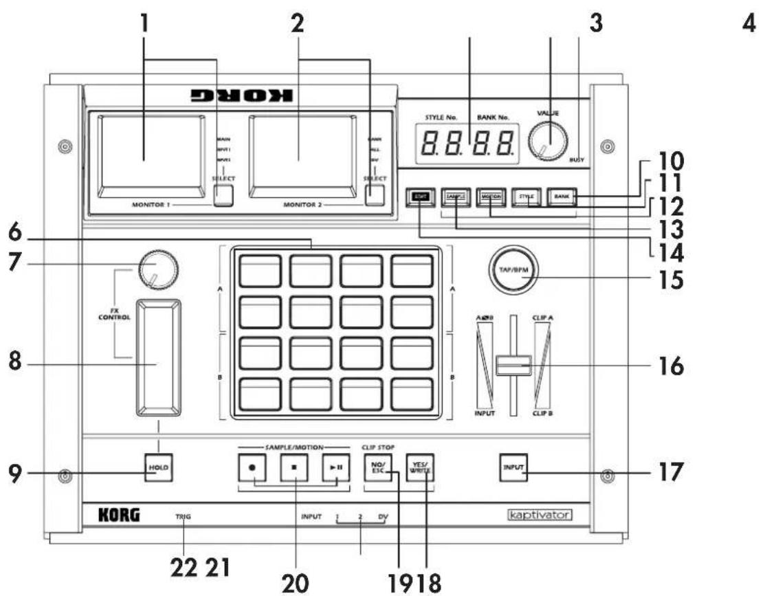
1. MONITOR 1, SELECT key
MONITOR 1 generally displays the video signal that is being sent from the MAIN OUT jack (MAIN). It can also display the video signals coming in through the VIDEO INPUT 1 (INPUT 1) or VIDEO INPUT 2 (INPUT 2) jacks.
Press the SELECT key to choose one of the three modes described above. (p.12) Holding down the EDIT key and pressing the SELECT key will allow you to adjust the brightness, contrast, and color balance of MONITOR 1. (p.12)
2. MONITOR 2, SELECT key
In MONITOR 2, you can choose to view all the clips currently assigned to the clip pads (BANK), the playback status of each position of the current routing assignment (ALL), as well as the digital video signal (DV) that is being received at the DV I/O connector.
Press the SELECT key to choose one of the three modes described above. (p.12) The DV input image cannot be selected if the DV I/O connector is set to OUT. (p.9) Holding down the EDIT key and pressing the SELECT key will allow you to adjust the brightness, contrast, and color balance of MONITOR 2. (p.12)
3. VALUE display
This shows the bank and style number, the name and value of the current parameter, and other status information.
4. VALUE knob
This knob is used to both select and change the value of various parameters.
This knob can also be used as an addition controller (Ext Value) by holding down the YES/WRITE key and turning the VALUE knob. When using the factory settings, this function will control the dissolve rate (the time for transitioning between clips). Style Edit parameters allow you to assign various parameters to this function.(p.19, 31)
5. BUSY indicator
When this indicator is lit, data is either being read from or written to the internal hard drive. In normal operation, pressing the NO/ESC key will stop the currently-playing clip, and the BUSY indicator will go dark.
NOTE Never turn off the power while the BUSY indicator is lit. Doing so may damage the hard disk.
6. CLIP pads
These pads are used to select and play sampled video clips. There are sixteen pads; the upper eight are Group A, and the lower eight are Group B. Group A is green, and Group B is orange. The currently selected key will light red. Choose "BANK" for MONITOR 2 to see the list of clips in the INDEX screen.
In Clip Edit, you can specify the playback points, the index frame, and a playback pattern (such as one-shot, loop, or reverse) for each clip.
7. FX CONTROL knob controller
This knob is mainly used to provide realtime control of the effects. The parameter being adjusted by the knob will depend on the style or effect that is currently selected.
Style Edit parameters allow you to assign the knob to a variety of different functions.
8. FX CONTROL ribbon controller
The ribbon controller is mainly used to provide realtime control of the effects. Two parameters can be assigned to the ribbon: touching the ribbon, regardless of position, can be assigned to one parameter; position on the ribbon to another. The parameters being adjusted by the ribbon controller will depend on the style or effect that is currently selected.
Style Edit parameters allow you to assign the ribbon controller to various functions.
9. HOLD key
When the HOLD key is turned on (lit red), the last value detected by the ribbon controller will be held, and will continue to apply the effect in its current state.
Style Edit parameters allow you to assign this key to various functions.
10. BANK key
Each time you press the BANK key, it will toggle between Group A (green) and Group B (orange). When the BANK key is blinking green, you can assign a bank of clips to the upper eight CLIP pads, or group A. When the BANK key is blinking orange, you can assign a bank of clips to the lower eight CLIP pads, or Group B. If the BANK key is not blinking (i.e. when the STYLE key is blinking), pressing it will also switch MONITOR 2 to the BANK setting.
11. STYLE key
Each time you press the STYLE key, it will alternate between selecting styles (green) and selecting effects (orange). When the STYLE key is blinking green, you can use the VALUE knob to select a style. When the STYLE key is blinking orange, you can use the VALUE knob to select an effect. If the STYLE key is not blinking (i.e. when the BANK key is blinking), pressing it will also switch MONITOR 2 to the ALL setting.
12. MOTION key
Press this key to enter Motion Sequence mode. When this key is blinking red, you are in the Motion Sequence mode. Here you can select, record and playback the operation of the FX CONTROL knob & ribbon, slider, CLIP pads, HOLD key, etc. Press this key again to exit Motion Sequence mode. You cannot exit this mode while a Motion Sequence is playing.
13. SAMPLE key
Press this key to enter Sample mode. When this key is blinking red, you are in the Sample mode. Here you can record (sample), edit and save video information, or "clips". Press this key again to exit Sample mode. You cannot exit this mode if an empty clip is selected.
14. EDIT key
The EDIT key is used in conjunction with other keys to access a variety of editable parameters and functions. When the SAMPLE, MOTION, STYLE or BANK keys are blinking, holding down the EDIT key while you press one of these blinking keys will access the edit functions for that mode. Hold down the EDIT key while you press the INPUT key to select whether the DV jack is set to input or output. Hold down the EDIT key while you press the YES/WRITE key to access the Utility mode. Hold down the EDIT KEY and press one of the clip pads to edit the actual clip itself. This key will blink red while you're editing. Press the NO/ESC key twice to exit the current edit mode.
15. TAP/BPM key
The kaptivator can be set to start and play clips, as well as vary certain effect parameters in sync with a BPM tempo source. This key is used when selecting the Manual mode, where the tempo is set by the kaptivator's internal clock; to tap in a tempo in the Tap Tempo mode; or to arm the kaptivator to detect an external audio tempo source in the Auto BPM mode. This key will flash red on each beat, and flash green on the first beat of the measure (every four beats). While the tempo is being edited, this key will flash orange until the new tempo is entered.
16. Slider
Primarily, the Slider is used to crossfade between two video sources or images. Style Edit parameters also allow you to assign the Slider to various functions.
17. INPUT key
Pressing this key will cycle through the various video sources that can be connected to the kaptivator. The input source that is currently selected will be the one that is processed and used by the kaptivator. Each time you press this key, the input signal will change from INPUT 1 → INPUT 2 → DV-IN (only if selected) → OFF (black screen) → INPUT 1 ... The VIDEO INPUT indicator (see 21.) shows which source is currently selected The lit color of this key indicates the type of routing specified by the current style. Red = single, Dark (unlit) = dual, Green = 3 layer, Orange = separate output (p.14)
18. YES/WRITE key
Press this key to finalize a setting or execute an operation.
19. NO/ESC key
Use this key to cancel a setting or operation. In normal operation, pressing this key while a clip is playing back will stop playback.
20. ● / ■ / ▶ II (REC/STOP/START&PAUSE) key
These keys are used in Sampling mode and Motion Sequence mode.
When playing back a Motion Sequence, the ▶ II key will be lit green. In the Main Out Capture mode, the ▶ II key will blink red if there is data in the Capture buffer, and will be lit red as the Capture file plays.
21. VIDEO INPUT indicator
This indicator shows which video input source has been selected by using the INPUT key (see 17.). (vss p.14)
22. AUDIO TRIG indicator
This indicator will light when the level of the external audio signal (connected to the AUDIO TRIG INPUT) exceeds the current TRIG LEVEL setting. (p.16)
B.Front panel
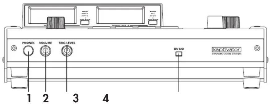
1. PHONES jack
This stereo 1/4" headphone jack can be used to monitor the audio signal that is being received via the rear panel AUDIO TRIG INPUT jacks.
2. PHONES volume knob
This adjusts the volume level of the headphone output.
3. TRIG LEVEL knob
This knob adjusts the audio trigger / effect control / auto BPM level. To set a reliable or stable trigger level, you can adjust this knob while watching the AUDIO TRIG indicator.
4. DV I/O connector
The DV connector of your DV camera or the IEEE 1394 connector of your computer can be connected to this jack. Only DV video signals can be received or sent from this connector. This connector cannot transfer data such as files, or input/output audio signals.
C.Rear panel
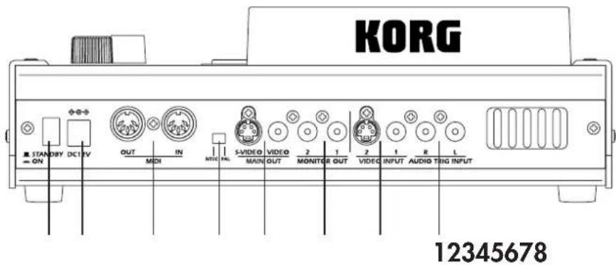
1. AUDIO TRIG INPUT L/R jacks
These RCA-style jacks can receive line-level audio signals. The incoming audio signal can be used for BPM detection or to control effects.
2. VIDEO INPUT jacks
These jacks can receive video signals from a DVD player or other video devices.
VIDEO INPUT 1: Receives a composite video signal.
VIDEO INPUT 2: Receives an S-video signal.
3. MONITOR OUT jacks
These jacks transmit a video signal identical to what is currently displayed by the on-board monitor screens.
MONITOR OUT 1: Transmits the image displayed by MONITOR 1.
MONITOR OUT 2: Transmits the image displayed by MONITOR 2.
4. MAIN OUT jacks
The MAIN OUT jacks send the final output of the kaptivator, after all the internal processing, mixing, etc. This is the same image that is displayed when you've set the MONITOR 1 SELECT setting to "MAIN".
VIDEO: Transmits a composite video signal.
S-VIDEO: Transmits an S-video signal.
5. PAL/NTSC switch
This switches the video signal format (NTSC or PAL). You must turn off the power before changing the setting of this switch.
6. MIDI IN / MIDI OUT connectors
You can use these jacks to connect the kaptivator to other MIDI devices - sequencers, music samplers (e.g., ESX-1), keyboards, etc..
7. Power supply jack
Here is where you plug in the power supply. Only use the dedicated AC adapter that was included with the kaptivator.
8. Power switch
This switch turns the power on and off. And once again, never turn off the power while the BUSY indicator is lit. Press the NO/ESC key until the BUSY indicator goes out; then you can safely turn the power off.
3. Connection diagram
Basic connections
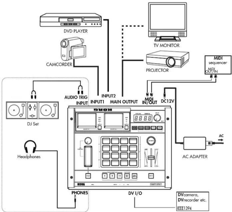
flowchart
graph TD
    A[" DVD PLAYER "] --> B[" CAMCORDER "]
    B --> C[" DJ Set "]
    C --> D[" Headphones "]
    D --> E[" PHONES "]
    E --> F[" DV I/O "]
    F --> G[" AC ADAPTER "]
    G --> H[" MIDI sequencer MIDI OUT/IN "]
    H --> I[" TV MONITOR "]
    I --> J[" PROJECTOR "]
    J --> K[" HDMI IN/OUT "]
    K --> L[" INPUT1 INPUT2 "]
    L --> M[" Audio TRIG INPUT "]
    M --> N[" MEMD"]
    N --> O[" DVD"]
Selecting the DV connector input/output setting
1 Hold down the EDIT key and press the INPUT key.
2 Use the VALUE knob to select either "in" or "out" in the VALUE display.
3 P r ess the YES/WRITE key twice. If you decide to cancel the setting, press the NO/ESC key twice.
About video signal formats
The kaptivator supports both the NTSC and PAL video signal formats. NTSC is the format used in the United States and Japan, while PAL is the format used in the United Kingdom and Europe.
Set the NTSC/PAL switch according to the video signal format of the equipment you're using. The kaptivator will not operate correctly if the video signal format is incorrect. Also, the kaptivator will not operate correctly with non-interlaced video signals.
Playing copy-protected video from a commercial DVD
Copy-protected DVD video cannot be used as a video source. If you connect this type of signal to the kaptivator's INPUT jack, the image will not appear. In addition, a warning of "PROTECTED" may appear in some cases, if you've selected ALL as the setting for MONITOR 2.
4. Basic concepts and operation
Concepts
Sampling video
The kaptivator saves sampled video on its internal hard drive as "clips."
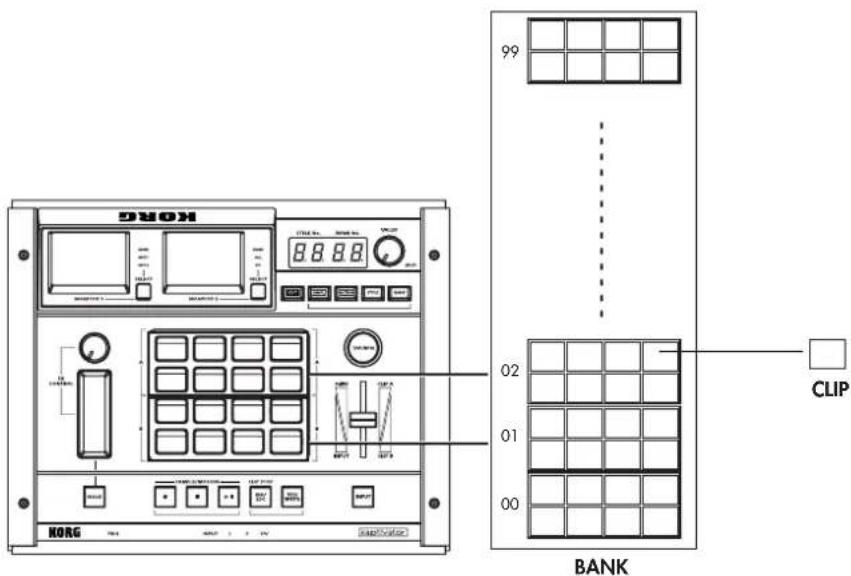
These saved clips are managed as "banks", each containing eight clips.
You can assign each of these banks to either of the two groups of clip pads (Group A contains the upper eight clip pads; Group B contains the lower eight) and play back these sampled video clips. The same bank can be assigned to both groups simultaneously.
Styles
The heart of the kaptivator's ability to perform as a realtime video instrument is the Style. Each individual style is really a complete processing scheme consisting of a specific routing setting; a video effect; a transition setting; various controller assignments and more. You can edit, create, modify and save 100 individual styles in the kaptivator. By simply switching to a new style, you can instantly re-configure the kaptivator and all its settings.
Terms
Style
Each “style” contains settings for routing, effects, playback synchronization, and controller assignments. You can switch between styles during playback, or edit and store styles according to your needs. One hundred styles can be stored in the kaptivator.
Clip
A "clip" is an individual segment of sampled video material, together with its various settings, which can be saved, stored to a bank, and assigned to one of the sixteen clip pads. The kaptivator can store up to 800 clips. You can specify the start point, stop point, loop point, playback style and other settings for each clip.
Bank
A "bank" is a set of eight clips that can be assigned to the clip pads. You can create, save and assign clips ("register") up to one hundred banks.
Group
The sixteen clips pads are organized into two groups. Group A contains the upper eight clip pads; and Group B, the lower eight. Each bank of clips can be assigned to either group - or both. The settings saved in a style will apply to the entire group.
Routing
The kaptivator is extremely flexible, in that many of the elements of a style can be arranged into different routing scenarios. For example, a routing setting can specify the number of video sources (Group A, Group B, DV Camera in, etc.), which sources will be mixed by the slider, where the effect processor is inserted (before the slider, after the slider, only to Group A, etc.) along with what information is displayed in MONITOR 2 (with ALL selected).
Motion Sequence
Your "live" movements - pressing clip pads, operating the slider and FX controllers, selecting banks, etc. - can be recorded as a Motion Sequence, and played back with any style. The kaptivator will store up to 100 Motion Sequences.
BPM
BPM (Beats Per Minute) indicates the tempo of a song in terms of the number of quarter notes per minute. Higher BPM settings indicate a faster tempo. The kaptivator can change clips and vary effect parameters in sync with a BPM tempo source.
Basic operation — Playback
1. Turning the power on/off
Power
To turn the power on
1 Connect the AC adapter, your input devices, and your output devices.
2 P r ess the power switch to turn the power on.
After a few moments, the VALUE display will indicate the currently selected style and bank.
STYLE No. BANK No.
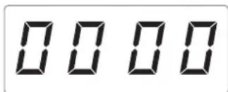
NOTE You can specify the bank and style number that will be selected when the power is turned on. (p.28)
To turn the power off
To turn the power off, press the NO/ESC key several times until the BUSY indicator goes dark; then press the power switch to turn it off.
NOTE Never turn off the power while the BUSY indicator is lit. Doing so may damage the kaptivator's internal hard disk. So don't do it.
Monitors
The two color LCD monitors display different content.
MONITOR 1 displays the MAIN OUT video signal, the video source connected to VIDEO INPUT 1 or the video source connected VIDEO INPUT 2.
MONITOR 2 displays the bank list (a still image from each clip), all the video material associated with a style (inputs, output, transition, etc.) or the DV input.
Changing the content of the monitors
Pressing the MONITOR SELECT key will change the information being displayed in the monitor associated with that key.
The content of the monitors can also be set to change automatically when you select a style. (p.30: Style Parameter List, Monitor select setting)
Adjusting the monitors
The monitors can be adjusted individually to provide easy visibility and to compensate for factors such as viewing angle, location, surroundings, ambient lighting, etc.
1 Hold down the EDIT key and press the MONITOR 1 or 2 SELECT key.
2 P r essing the EDIT key will cycle through the following parameters.
Brightness: "br" will blink in the VALUE display, followed by the current value (00–99)
Contrast: "cn" will blink in the VALUE display, followed by the current value (00–99)
Color Balance: "cL" will blink in the VALUE display, followed by the current value (00–99)
3 As you watch the monitor, turn the VALUE knob to set each parameter.
4 P r ess the YES/WRITE key twice to save your settings.
If you decide not to save your settings, press the NO/ESC key twice.
2. Selecting and playing video
Playing a clip
1 P r ess one of the clip pad keys that are lit (green for Group A, orange for Group B). The selected clip pad will light red, and the clip that is registered to that pad will play.
2 Use the ribbon controller or slider etc. to modify the video while it plays, or press another clip pad to play a different clip.
NOTE Depending on the current style, you may not see anything in the MAIN output if the slider is set to its minimum or maximum value. Set the slider to its middle or opposite position.
Changing the transition time between clips (Dissolve Rate)
To change the transition time between clips, hold down the YES/WRITE key. In the VALUE display, "E - " will start blinking. Continue to hold down the YES/WRITE key and turn the VALUE knob to set the dissolve rate (00–99). When the value is 99, the transition time will be approximately eight seconds.
Selecting a bank
1 Press the BANK key. The currently selected bank number is indicated by the two right-hand digits in the VALUE display.
2 When the BANK key is blinking green, you can select a different bank for Group A. When the BANK key is blinking orange, you can change the bank assigned to Group B.
3 P r ess the MONITOR 2 SELECT key until the BANK indicator light is lit.
4 As you watch MONITOR 2, rotate the VALUE knob to select a different bank.
Selecting a style
1 If you want to switch styles, press the STYLE key to enter Style mode. Each time you press this key, you will alternate between selecting a style (the STYLE key will blink green) and changing the effect assigned to the current style (the STYLE key will blink orange).
2 With the STYLE key blinking green, rotate the VALUE knob to change the style number, indicated by the two left-hand digits in the VALUE display.
3 P r ess the flashing YES/WRITE key to confirm your style selection.
If you decide not to change styles, press the flashing NO/ESC key, or use the VALUE knob to return to the previous STYLE. The YES/WRITE and NO/ESC keys will stop flashing. If you change styles while a clip is playing, the clip may stop. If you select a style that contains a different routing, the clip will stop playing.
Changing the effect
1 With the STYLE key blinking orange, rotate the VALUE knob to change the effect assigned to the current style. The effect number is indicated by the two left-hand digits in the VALUE display.
2 P r ess the flashing YES/WRITE key to confirm the effect change. If you decide not to change the effect, press the flashing NO/ESC key,
3 Operate the ribbon controller to see what the effect does.
NOTE If the current style is saved with "no effect" assigned, the VALUE display will indicate "--" and you won't be able to change effects.
3. Working with external video sources
Viewing an external video source
To view the video source connected to the VIDEO INPUT 1 jack, press the MONITOR 1 SELECT key to select INPUT 1. To view the video source being received by the INPUT 2 connector, select INPUT 2.
You can use MONITOR 2 to view the video source being received at the DV connector. Use the MONITOR 2 SELECT key to choose DV.
NOTE Set the DV connector setting to "in." (p.9: DV connector in/out setting)
NOTE The image that is being input to the DV connector will be slightly delayed. We recommend that you use the INPUT jack for realtime use, such as for live video.
To select an external video source
Press the INPUT key to select one of the external video sources connected to the kaptivator.
The VIDEO INPUT indicator shows the status of the selected input.
Input 1 Lit: Currently selected
Blinking rapidly: No connection, or wrong signal format
Blinking slowly: Copy-protected signal was detected
Input 2 Lit: Currently selected
Blinking rapidly: No connection, or wrong signal format
Blinking slowly: Copy-protected signal was detected
DV Input Lit red: Currently selected (DV set to input)
Blinking rapidly: No connection
Blinking slowly: Copy-protected signal was detected
Green: Indicates that the DV connector is set to "Out"
dark (unlit) Input is off (black screen), or Main Out Capture is selected
Mixing an external video source with a clip
1 P r ess the STYLE key until it blinks green.
2 T urn the VALUE knob to select "31" (style number), and press the flashing YES/WRITE key. For this example, we've chosen a style whose routing setting is "single."
3 P r ess the MONITOR 2 SELECT key to select ALL. This lets you monitor the video input, the video selected by the clip pads, and the combination of these (the image that is sent from MAIN OUT). Use the MONITOR 1 SELECT key to select MAIN. Now you can monitor the mixed image (the image that is sent from MAIN OUT) in MONITOR 1.
4 Use the slider to mix between the external video source and the clip pad playback, and use the ribbon controller to apply the effect assigned to this style. The effect will be assigned to the clip pad playback, the external video source, or the mixed signal, depending on the routing setting of the current style.
4. Synchronizing to music
You can use the BPM setting or the playback from an external audio source to control the playback speed or the start timing of a video clip, or to control the current effect.
NOTE If you synchronize the clip start timing to the BPM, it may be delayed by several frames.
Setting the BPM
Setting the BPM manually
1 Hold down the EDIT key and press the TAP/BPM key to select Manual mode.
2 Rotate the VALUE knob to change the BPM value shown in the VALUE display. The decimal point in the display will blink.
3 P r ess the YES/WRITE key or the TAP/TEMPO key to complete the setting. The decimal point will stop blinking, indicating the new tempo is set. If you want to cancel the setting, press the NO/ESC key.
NOTE You can't switch clips while setting the BPM.
The Tap Tempo function
If you don't know the BPM value, press the TAP/BPM key three or more times in rhythm with the song; the BPM of the song will be detected and shown in the display, and will be assigned as the current BPM setting.
Auto BPM setting
1 If you have a music source hooked up to the AUDIO TRIG INPUT jacks, hold down the TAP/BPM key for three seconds or longer, and the kaptivator will automatically detect the BPM of the song. You may have to adjust the TRIG LEVEL knob to get the best results. While the BPM is being detected, the decimal point will blink and the TAP/BPM key will flash orange.
NOTE The BPM cannot be detected if the music does not have a clear sense of beat.
2 P r ess the YES/WRITE key to confirm the setting. The decimal point will stop blinking and the TAP/TEMPO key will once again flash red on each beat, and green at the start of the measure. If no tempo is detected, the kaptivator will continue to use the previous BPM setting. If you decide to cancel, press the NO/ESC key.
NOTE You can't switch clips while making the Auto BPM setting.
Synchronized playback using the BPM setting
Synchronizing the start of the clip to the BPM
1 Set the BPM using one of the methods described above.
2 Choose style number "88".
This style sets the start mode to "T2" so that clips will start in sync with the BPM. (p.31: Style parameter list, p.19: Style edit)
3 Press a clip pad. The clip will begin playing at the beginning of the measure (when the TAP/TEMPO light flashes green).
Synchronizing the clip playback speed to the BPM
1 Set the BPM.
2 Choose style number "00".
This style sets the clip "C3 (Playback reference speed setting)" to "r2" so that the clip play-
back speed will change in sync with the BPM. (p.31: Style parameter list, p.19: Style edit)
3 Select the clip that you want to play. Change the BPM. The clip playback speed will change according to the BPM.
Synchronized playback using an audio trigger
Adjusting the audio trigger level
1 Connect the playback from as external audio device such as a CD player or a DJ mixer to the AUDIO TRIG INPUT jacks.
2 As you watch the AUDIO TRIG indicator, adjust the trigger level using the TRIG LEVEL knob. The AUDIO TRIG indicator shows the state of the audio signal trigger level.
Dark (unlit): No input detected, Green: Minimum level detected, Orange: Level detected, Red: Maximum input
Synchronizing the start of the clip to the audio trigger
1 Adjust the trigger level to an appropriate level for the song, as described above.
2 Choose style number "87".
This style sets the start variation to "T3" so that the clip will begin playing when the audio input signal exceeds the trigger level. (p.31: Style parameter list, p.19: Style edit)
3 Press a clip pad. When the volume of the song exceeds the trigger level, the video clip will begin playing.
Using an external audio signal to control an effect
1 In addition to using an audio trigger, variations in the input level of an external audio source can also be used to control certain parameters.
Connect an external audio device and set the trigger level as described in the previous examples.
2 Choose style number "02".
This style assigns the effect control setting to "A1," and varies the parameter in synchronization with the trigger level. (€ p.31: Style parameter list, p.19: Style edit)
3 Touch the ribbon controller to operate it. The amount of blurring will change according to the trigger level.
5. Using Motion Sequences
You can record and save up to one hundred sets of controller movements as “motion sequences,” and then select a motion sequence and play it back when desired. In addition to movements of the various controllers and operations on the clip pads, a motion sequence can also include bank or style selections and changes.
Playing a motion sequence
1 To enter Motion Sequence mode, press the MOTION key; the MOTION key will blink. Press the blinking MOTION key to exit Motion Sequence mode.
2 Use the VALUE knob to change the motion sequence number “-**-” shown in the VALUE display. If the “-” at both sides is blinking, this indicates an empty motion sequence that has not yet been recorded.
3 P r ess the YES/WRITE key to confirm your selection.
4 P r ess the key to playback the motion sequence. Press the key once again to pause.
5 P r ess the STOP key to stop the motion sequence.
If you've assigned the motion to once, playback will end automatically.
6 Press the blinking MOTION key to exit Motion Sequence mode. You can't exit Motion Sequence mode unless the motion sequence is stopped.
Looping the playback of a motion sequence
1 When the MOTION key is blinking, hold down the EDIT key and press the MOTION key; the EDIT key and MOTION key will blink.
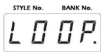
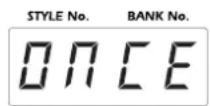
2 Use the VALUE knob to make the VALUE display read "LOOP." Choose "ONCE" if you don't want the motion sequence to loop.
Play repeatedly Play once
3 P r ess the YES/WRITE key twice to confirm the setting.
Recording a motion sequence
1 If the MOTION key is blinking, you are already in Motion Sequence mode. To enter Motion Sequence mode, press the MOTION key; the MOTION key will blink. Press the blinking MOTION key to exit Motion Sequence mode.
2 Use the VALUE knob to change the motion sequence number “-**-” shown in the VALUE display.
If the “-” at both sides is blinking, this indicates an empty motion sequence that has not yet been recorded. Choose a motion sequence number that has not yet been recorded, and press the YES/WRITE key.
NOTE If none of the motion sequences are empty, you'll need to erase one. (p.18: Erasing a motion sequence)
3 P r ess the REC key to enter standby mode. (The REC key will blink.)
4 Recording will begin when you perform an operation that can be recorded as a motion sequence.
5 P r ess the STOP key to stop recording the motion sequence.
Erasing a motion sequence
1 If the MOTION key is blinking, you are already in Motion Sequence mode. To enter Motion Sequence mode, press the MOTION key; the MOTION key will blink. Press the blinking MOTION key to exit Motion Sequence mode.
2 Use the VALUE knob to select the motion sequence number “-**-” (shown in the VALUE display) that you want to erase, and then press the YES/WRITE key.
3 Hold down the EDIT key, the NO/ESC key, and the MOTION key (all simultaneously). Of the motion sequence number (-^**-) , only the numerical portion will blink.
4 Press the YES/WRITE key twice to erase the recorded motion sequence. If you decide not to erase the motion sequence, press the NO/ESC key twice.
Customizing a Style —Style Editing
The kaptivator lets you create and store one hundred "styles." This section explains how you can create styles that are appropriate for the video material you're using and how you're using it.
During performance, you can change effects, wipe types, and controller settings simply by selecting a style.
NOTE The factory settings contain various styles programmed to demonstrate the kaptivator's capabilities.
1. Editing a style
The effects of editing a style will depend on how the video sources are connected and on the content of these sources.
Choosing a style
The most important element of a style is the “routing.” The routing determines the structure of the video sources you can use. If you’re using only clips saved internally, choose the Dual routing. If you’re using external video devices in your performance, choose the Single or Three Layer routing. If you’re using the MONITOR 2 OUTPUT independently, choose the Separate routing. See pages 33 through 37 for illustrations of the various routings available. After you’ve selected the appropriate routing for your situation, you can assign the function of each controller, and specify the effect and type variation.
Style editing
1 Select the style that you want to edit.
2 Hold down the EDIT key and press the STYLE key. The display will indicate "A1.**" and the EDIT key will blink.
3 To edit the A1. parameter, use the VALUE knob to change the value shown in the VALUE display.
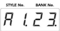
NOTE The decimal point following the parameter value will light if the value is identical to the saved value.
4 To edit the next parameter, press the EDIT key. Each time you press the EDIT key you will proceed to the next parameter. To return to the preceding parameter, hold down the EDIT key and press the YES/WRITE key.
5 T o see the results of your editing, press the YES/WRITE key.
Now you can check the changes you made to the style.
At this point, you can use the VALUE knob to select the desired save-destination style and press the YES/WRITE key to save the edited style and complete the procedure. If you want to continue editing without saving your changes, press the NO/ESC key.
Editing examples
Changing the operation of the ribbon controller
1 Select the style that you want to edit.
For this example, choose style number "04".
2 Hold down the EDIT key and press the STYLE key. The display will indicate "A1.**" and the EDIT key will blink.
3 P r ess the EDIT key several times to choose parameter B5.
Here you can choose the controller that will modify the effect. To choose the ribbon controller, choose a setting in the range of "G1"–"G4." With the "G1" setting, the effect will intensify as you move the controller from bottom to top. Conversely with the "G2" setting, the effect will intensify as you move from top to bottom. With the "G3" setting, the effect is at maximum at either end, and minimum in the center. The "G4" setting produces the opposite result, with the maximum effect in the center position.
4 When you're finished editing, press the YES/WRITE key. Use the VALUE knob to select the destination style location (style number) where you want to save the edited style. Then press the YES/WRITE key to finish saving. If you decide not to save the changes you made, press the NO/ESC key.
Changing the wipe type
1 Select the style that you want to edit.
For this example, choose style number "11".
2 Hold down the EDIT key and press the STYLE key. The display will indicate "A1.**" and the EDIT key will blink.
3 P r ess the EDIT key several times to choose parameter A2.
This parameter specifies the type of transition. Choosing "00" will specify a fade. In this example, let's select "03" to produce a wipe that changes the position of the images.
4 P r ess the EDIT key to select parameter A3.
This selects the controller that will perform the wipe operation. Choose "F1" if you want to specify the fader. Choose "F2" if you want to invert the direction of the fader operation.
5 P r ess the EDIT key to select parameter A4.
This parameter specifies the type of wipe and the variable range of the controller. If you want to create a wipe that pushes the image from left to right, specify a value in the range of "30"–"39." The second digit of the value specifies the range of fader movement. In this case, selecting "30" will produce a wipe using the entire range of the fader. Selecting "35" will wipe using half the range of the fader. Selecting "39" will cause the image to switch at the midpoint of the fader.
6 When you're finished editing, press the YES/WRITE key. Use the VALUE knob to select the destination style location (style number) where you want to save the edited style. Then press the YES/WRITE key to finish saving. If you decide not to save the changes you made, press the NO/ESC key.
Creating a clip —Sampling and Quick Editing
1. Sampling
Sampling video
Sampling a video input source
1 Press the SAMPLE key; it will blink, and you will be in Sampling mode. You can press the SAMPLE key once again to exit Sampling mode.
2 Use the VALUE knob to specify the sampling time. Samples are created and stored using memory units that are 8 seconds long. You can specify a time length from eight seconds through 600 seconds (ten minutes) in eight-second steps. The default is eight seconds.
NOTE The sampled video is managed in units of data that are each eight seconds long. For example, if the image you want to sample is fourteen seconds long, it will require two of these eight second data units, and will actually occupy sixteen seconds of sampling time on the hard drive.
3 Selecting an empty clip.
If you press the YES/WRITE key at this time, a vacant clip pad in the lowest-numbered available bank will be selected. You can also manually select any empty clip pad in any bank. If you select a clip pad that already has a clip assigned to it, the display will indicate "OCCP". If there is not enough available storage space when you press the clip pad, the display will indicate "FULL".
The kaptivator will be in sampling-ready mode. (The clip pad and the REC key will blink.)
4 P r ess the INPUT key to select the external video input signal that you want to sample. You can also apply an effect to the input video while sampling it. If you want to do this, press the STYLE key at this point, turn the value knob to select an effect, and press the YES/WRITE key.
NOTE The effect selected in this case is only applied to the image being sampled. This will not change the effect setting of the style that was selected before you entered SAMPLE mode.
5 P r ess the REC key to begin sampling. Press the STOP key to stop. Sampling will stop automatically when the specified sampling time has elapsed.
6 If you want to continue sampling, press the YES/WRITE key to select the next empty clip, rotate the VALUE dial to set the sampling time, and repeat steps 4 and 5.
7 If you are finished sampling press the SAMPLE key to exit Sampling mode. If the kaptivator is in sampling-ready mode (The clip pad and the REC key are blinking), press the NO/ESC key, and then press the blinking SAMPLE key to exit Sampling mode
NOTE The Clip Edit parameters allow to adjust the playback speed, start point, end point, playback method, etc.
Time-lapse sampling
Extremely slow movements such as drifting clouds or opening flower blossoms can be captured using time-lapse video, and then played back to speed up the movement. Time-lapse video can also be used to make common things like cars and people play back at an artificially fast speed.
1 P r ess the SAMPLE key to enter Sampling mode.
2 Hold down the EDIT key and press the SAMPLE key; the EDIT key and SAMPLE key will blink, and the display will indicate the time-lapse ratio.
NOTE You can turn the knob quickly to make larger changes in the numerical value.
Turn the VALUE knob to specify the resulting playback speed.
You can specify a value between "1" and "5400" times normal.
For example if you've specified 8 seconds as the sampling time:
x "2" will record for 16 seconds, and the playback will be double-speed.
x "10" will record for approximately 1 minute 20 seconds, and the playback will be ten times normal speed.
x "100" will record for approximately 13 minutes 20 seconds, and the playback will be one hundred times normal speed.
x "1000" will record for approximately 2 hours 13 minutes 20 seconds, and the playback will be one thousand times normal speed.
x "5400" (the maximum setting) will record for approximately 12 hours.
Press the YES/WRITE key twice to complete the Slow Sampling settings.
3 Begin recording the video as for conventional sampling.
NOTE If you're sampling from a camera, we recommend that you use a stable tripod. In addition, be aware that since the lighting may change if you're recording for an extended time, it's a good idea to use appropriate illumination.
Main Out Capture
Using this function, the processed and mixed video that is being sent from the MAIN OUT jack can be temporarily captured into memory. This captured video can then be used as an input source for further processing and mixing, used as an input source in Sample mode and then “resampled” and saved to a clip. The Main Out Capture function can accommodate a maximum of approximately eight seconds.
Capturing video and using it as an input source
1 Hold down the EDIT key and press the YES/WRITE key to enter Utility mode. In Utility mode, enable the Main Out Capture function. (p.27)
NOTE Any existing Main Out Capture data will be erased when you enter Utility mode.
NOTE The bank display response will be slower if you enable Main Out Capture. (p.27)
2 Exit Utility mode and return to Play mode.
3 Press the REC key (you will be in Pause mode), and then press the REC key once again to begin capturing.
4 Use the clip pads, sliders, and effects to control your video performance.
NOTE By pressing the ▶ II key while capturing, you can continue capturing without stopping after eight seconds. The eight seconds of video preceding the point at which you pressed the STOP key will be captured.
5 Capture will end when you press the STOP key or when approximately eight seconds have elapsed. At this time, the ▶key will blink red, indicating that capture has finished.
6 Using a style whose routing is other than "Dual," press the INPUT key and select "CAPTURE" as the input source.
7 Press the ▶ II key to play back the captured video, and perform as desired by mixing video clips etc.
8 To delete the captured video, hold down the EDIT key, the NO/ESC key, and the PLAY key (all three simultaneously).
Resampling to a clip
If you want to resample the video as a clip, return to Sample mode and select "CAPTURE" as the input signal.
2. Clips
For each piece of video material that you sample, you can specify the playback start point, end point, loop point and looping method; these settings can then be saved along with the video material as a "clip." Even when using the same piece of video material, you can change the start point etc. and save it as a different clip.
Copying a clip
Here's how you can copy an existing clip, edit it, and save the edited result in a different bank.
Copying a single clip
1 Hold down the EDIT key and press the BANK key; the EDIT key and BANK key will blink, and the Clip Copy operation will be selected. The clip pad that you want to copy is called the copy-source, and the clip pad where the copy will be saved is the copy-destination.
2 Select the copy-source clip pad. In MONITOR 2, a red frame will appear around the copy-source clip pad.
3 Select the copy-destination clip pad. A blue frame will appear around the copy-destination clip pad.
NOTE You can't copy to a location in which a clip has already been saved. If there is no available copydestination, you'll need to erase a clip to make space.
4 P r ess the YES/WRITE button twice to copy the clip.
Press the NO/ESC key once to un-select the copy destination (blue frame).
Press the No/ESC key a second time to un-select the copy-source (red frame).
To cancel the entire Clip Copy operation, be sure the copy destination and copy-source have been un-selected, then press the NO/ESC key twice.
Erasing a clip
Erasing the contents of a clip to create a blank clip
1 Hold down the EDIT key, the NO/ESC key, and the clip pad that you want to erase (all three together).
The clip pad and the EDIT key will blink, and the VALUE display LED will blink "ErAS".
2 Press the YES/WRITE key twice to erase the selected clip. If you decide not to erase, press the NO/ESC key twice.
NOTE You can't erase a clip whose Protect setting was turned "on" in Clip Edit mode. You must first turn Protect off before erasing the clip.
NOTE You can't recover an erased clip. If the sampled video material used by the erased clip is not used by any other clip, the sampled video material itself will also be erased.
Editing a clip
You can specify the way in which a clip will play, and the BPM value that determines its playback speed. You can also protect a clip to prevent it from getting erased or modified.
Clip editing
1 Hold down the EDIT key and press the clip pad of the clip you want to edit. The selected clip pad will blink orange during editing.
2 T urn the VALUE knob to choose the clip Playback Type - T1. T2. T3 or T4 from pages 40 through 43. This is the first digit (after the "T") in the VALUE display. (p.40, Playback Type and Playback Pattern selection)
3 P r ess the EDIT key, and turn the VALUE knob to select the Playback Pattern. This is the second digit in the VALUE display. (sp.40, Playback Type and Playback Pattern selection)
If playback type 1 or type 3 was selected in step 2, use the following procedure to edit the clip
4 a.) Press the EDIT key, and specify the start point using seconds (S.000) and frames (S.F.00).
NOTE Use the slider to adjust the seconds value, and use the VALUE knob to adjust the frames.
b.) Press the EDIT key, and specify the end point using seconds (E.000) and frames (E.F.00).
c.) Press the EDIT key, and specify the loop point using seconds (L.000) and frames (L.F.00).
NOTE The loop point is only available if you selected playback type 3 in step 2
d.) Press the EDIT key, and specify the INDEX point using seconds (I.000) and frames (I.F.00).the INDEX point will specify the point that you want to use as the still image in the bank display.
e.) Press the EDIT key and rotate the VALUE knob to specify the BPM (b.000) value.
The BPM you specify here is used only if you select a style that includes a BPM synchronization function. You can also use the TAP/BPM key to enter the BPM value (p.14).
Set the BPM value to match the sense of beat of the clip's video material.
If playback type 2 or type 4 was selected in step 2, use the following procedure to edit the clip
4 a.) Press the EDIT key and rotate the VALUE knob to specify the BPM (b.000) value.
The BPM you specify here is used only if you select a style that includes a BPM synchronization function. You can also use the TAP/BPM key to enter the BPM value (p.14).
Set the BPM value to match the sense of beat of the clip's video material.
b.) Press the EDIT key, and specify the start point using seconds (S.000) and frames (S.F.00).
NOTE Use the slider to adjust the seconds value, and use the VALUE knob to adjust the frames.
c.) Press the EDIT key, and set the end point by specifying the number of beats from the start point (E.b.00)
d.) Press the EDIT key, and set the loop point by specifying the number of beats from the start point (L.b.00)
NOTE The loop point is only available if you selected playback type 4 in step 2
e.) Press the EDIT key, and specify the INDEX point using seconds (I.000) and frames (I.F.00).the INDEX point will specify the point that you want to use as the still image in the bank display.
5 If you do not want to save your clip edits, press the NO/ESC key twice. To save your clip edits, press the YES/WRITE key once. Now you can choose to Protect the clip, to prevent further editing or accidental erasure. Use the VALUE knob to select Protect On (P. on) or Protect Off (P. off) and press the YES/WRITE key again to save your edits and Protect setting.
Turning Protect On or Off
1 Hold down the EDIT key and press the clip pad of the clip you want to edit.
2 P r ess the YES/WRITE key.
3 Use the VALUE knob to turn the Protect setting on or off.
4 P r ess the YES/WRITE key to save the setting.
3. Banks
Eight clips are saved together as a "bank." You can save one hundred banks of clips. (Maximum 800 clips of 8 seconds; Maximum total video recording time is approximately 1 hour 46 minutes)
Selecting a bank
You can select a bank and assign it to either group of clip pads, Group A (the upper eight clip pads) or Group B (the lower eight clip pads). You can select a new bank while a clip is playing and you can select the same bank for both groups.
Assigning a bank to a clip pad group
1 Press the BANK key. When the BANK key is blinking green, you can assign a new bank to Group A. When the BANK key is flashing orange, you can assign a new bank to Group B.
2 Use the VALUE knob to change the "BANK No." indication shown in the VALUE display and assign that bank to the selected group
Copying a bank
You can copy the currently selected bank by setting one group as the copy-source, and the other as the copy-destination
Copying an entire bank of clips
1 Hold down the EDIT key and press the BANK key; the EDIT key and BANK key will blink, and you'll be ready to copy clips.
2 Use the VALUE knob to select the copy-source bank, and press any clip pad twice in the copy-source bank. The eight copy-source clips shown in MONITOR 2 will be indicated by a red frame. The BANK key will now indicate the other group
NOTE You can't copy if you're unable to select a vacant bank. If there is no available copy-destination, you'll need to erase clips (p.23) to create a vacant bank.
3 Use the VALUE knob to select the group for the copy-destination bank. If the copy-destination bank is empty, the eight clips will be indicated by a blue frame.
4 Press the YES/WRITE button twice to copy the bank.
Press the NO/ESC key once to un-select the copy destination (blue frame).
Press the No/ESC key a second time to un-select the copy-source (red frame).
Tocancel the entire Bank Copy operation, be sure the copy destination and copy-source have been un-selected, then press the NO/ESC key twice.
Utility mode
In this mode you can make basic settings and perform maintenance operations.
1. Operations in Utility mode
Entering Utility mode
Hold down the EDIT key and press the YES/WRITE key to enter Utility mode. The MONITOR 2 screen will show the Utility select screen.
NOTE You can't play back clips in Utility mode.
![*** UTILITY MODE ** HDD Free Main out capture MIDI setting Power on setup Backup Preset initialize +: [EDIT] +: [YES]](/content/2026/05/1002548/images/618753f0d6cff365380adc03c60706e0ff8250142f0353811f8587ee59cb75b5.jpg)
Navigating the Utility mode
Press the EDIT key to choose a utility function. Each time you press the EDIT key the next lower item will be selected. After you've selected the item you want to execute, press the YES/WRITE key to display the options for the selected function. Many utility functions have sub-menus that operate the same way. Once you have selected an individual feature, use the VALUE knob to adjust the parameter. Press the YES/WRITE key twice to confirm your edit and return to the previous menu. If you decide not to keep your edit, press the NO/ESC key twice to return to the previous menu.
2. Utility menu items and procedures
This section explains the content of each utility menu item, and how to use it.
HDD free:
This shows the remaining space on the hard disk.
![** UTILITY MODE ** HDD free 100 % +8 [NO YES]](/content/2026/05/1002548/images/a8b723e04c9dda91cbee7e7775b881cc17c2eebd3592b9818f868b9475e07b6e.jpg)
Main out capture:
This enables/disables the Main Out Capture function. We recommend that you leave this set to "Disable" unless you are currently using the Main Out Capture function. Leaving it set to "Enable" while this function is not being used will slow down the bank list display.
![** UTILITY MODE ** Main out capture Disable [VALUE]](/content/2026/05/1002548/images/36e73963407fc09252b6840e31d04b569da1d232979cb32b004c15ddd2ec70d2.jpg)
MIDI setting:
Here you can adjust the kaptivator's MIDI settings, such as transmitting or receiving MIDI clock, MIDI channel, and control change settings. The kaptivator cannot send and receive MIDI clock information at the same time.
![*** UTILITY MODE ** MIDI setting 1/2 Channel 1 Touch [C] CC#92 Hold [D] CC#91 Ext. [E] CC# 5 Slider [F] CC# 8 Ribbon [G] CC#13 Knob [H] CC#12 +: [EDIT] +: [YES]](/content/2026/05/1002548/images/7218cb8651f0f146c1eb9300f8a187d2ea62ad7077c4d63a16b5dc8b0710c6d7.jpg)
![*** UTILITY MODE ** MIDI setting 2/2 Bank A CC#18 Bank B CC#17 Style(Pr)Enable Style FX CC#80 Pad(Note)Enable Clock Disable +: [EDIT] +: [YES]](/content/2026/05/1002548/images/db8af0522a3f7e0b3b9c7b27a2916415ff5aaf2c7d9c4791ec1e576368338661.jpg)
Setting the control change number
The kaptivator can receive or send MIDI clock for synchronizing with other devices, and can be set to any MIDI channel. Additionally, each of the kaptivator's controllers can be assigned
a MIDI control change number from CC#1 through CC#31, CC#64 through CC#95, or Pitch Bend. Each controller can also be individually set to enable ("CC") or disable ("cc"). You cannot adjust the value of a disabled parameter.
Power on setup:
You can specify the style and the banks that will be selected when the power is turned on.
![** UTILITY MODE ** Power on setup Style 00 Bank A 01 Bank B 00 +: [EDIT] / [VALUE]](/content/2026/05/1002548/images/880e31f6e5242225754b95c316644632b2a7bcc2957a61650b493185abb8e07f.jpg)
Backup:
Sampled video data and edited clip settings can be backed up to a DV camera or other external DV storage device. Global settings, style data and motion sequences (individually or in blocks of ten) can be backed up to a MIDI filer, sequencer or other MIDI storage device. The MIDI device must be able to initiate and send a dump request message.
Backing up video data to an external device
Sampled video together with its management data and clip data can be backed up to a DV device in a single operation.
1 Enter Utility mode.
2 P r ess the EDIT key to select "Backup," and press the YES/WRITE key.
![*** UTILITY MODE ** Backup Video data HIDI exclusive +: [EDIT] +: [YES]](/content/2026/05/1002548/images/5e613af1772908021a1aa7297e66bd1576855fdfbc3ebbe0671cf31ce4df5ce1.jpg)
3 Select "Video data," and press the YES/WRITE key.
![** UTILITY MODE ** Backup Video data Dump Restore +: [EDIT] +: [YES]](/content/2026/05/1002548/images/4696d78da3dbafb4d044cbdc5217a3a79bbe4b3bf8c6deffc4f12c9052c34fcc.jpg)
4 Select "Dump," and press the YES/WRITE key.
5 Select "Dump start number." Normally you will specify "000."
![** UTILITY MODE ** Backup Video data Dump 900 [VALUE]](/content/2026/05/1002548/images/f156cec576ff963ba19a45f65865244be5b9fb4bc6f5c027998f15e769d789d0.jpg)
At this point, the MAIN out will display the following data screen:
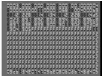
When this cut & clip data screen appears in MAIN out, put your external device in record mode, and begin video recording.
6 P r ess the YES/WRITE key twice to begin the backup.
The MAIN output will alternate between the cut & clip data screen and the cut image (maximum of approximately two hours). When the backup is completed, stop recording. NOTE The resolution will be converted if you backup between different data formats (NTSC/PAL) or operation modes (NTSC/PAL).
NOTE If you repeatedly backup and restore the same clip, the image quality will decline.
NOTE If you save NTSC data as a PAL signal, it will take approximately 1.2 times longer to save the data. (If you save PAL data as an NTSC signal, it will take approximately 5/6 the time.)
Restoring video data
Sampled video and clip data can be restored in a single operation.
1 Enter Utility mode.
2 P r ess the EDIT key to select "Backup," and press the YES/WRITE key.
3 Select "Video data," and press the YES/WRITE key.
4 Select "Restore," and press the YES/WRITE key.
From your external device, play back the backup video into the kaptivator.
5 When the first clip data screen begins to play, immediately press the YES/WRITE key twice to begin the restore operation.
When the restore operation is finished, stop playback. (When the operation is completed, there will be an indication of whether errors occurred, and how many occurred.)
NOTE If you decide to cancel during the restore operation, the data will be in an incomplete state, and will not be restored correctly. Also, if an error occurs during the operation, the video and data lost at that point will affect any clip that references that cut, so that it will not operate correctly.
NOTE If you performed a divided backup, the system will not operate correctly unless you restore the complete set of backup data.
Backing up style and motion sequence data
You can backup global data, style data, a single motion sequence, or a block of ten motion sequences to a MIDI filer, sequencer or other MIDI storage device.
1 Enter Utility mode.
2 P r ess the EDIT key to select "Backup," and press the YES/WRITE key.
3 P r ess the EDIT key to select "MIDI exclusive," and press the YES/WRITE key.
Transmit a dump request message from your external device.
If you're backing up motion sequence data, you'll also need to specify the number or block. When the kaptivator receives the dump request, it will transmit the backup data.
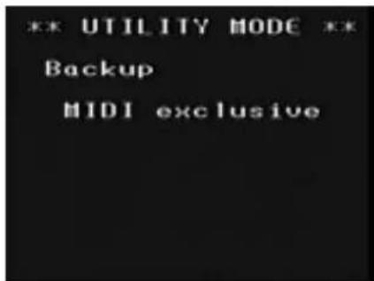
Restoring style or motion sequence data
You can restore the global data, style data, a single motion sequence, or block of ten motion sequences that you saved as a backup file.
1 Enter Utility mode.
2 P r ess the EDIT key to select "Backup," and press the YES/WRITE key.
3 P r ess the EDIT key to select "MIDI exclusive," and press the YES/WRITE key.
Transmit the backup data from your external device.
NOTE Since the restore operation will sequentially overwrite the data within the kaptivator, halting the restore operation before it has completed will mean that the motion sequence number that was being written at that moment will contain no data (i.e., erased).
Preset Initialize:
At any time, you can always restore the kaptivator to its original factory settings - including style, clip, and global settings.
NOTE Never turn off the power while initializing.
![*** UTILITY MODE ** Preset initialize 1. Global 2. Style 3. Motion 4. Clip 5. All(1~4) ↓: [EDIT] →: [YES]](/content/2026/05/1002548/images/a202c61c032b212344063dcaafe6a072732e1dfbf6b85ddd0e9c8da28036f8ee.jpg)
Parameter list
Style Parameter List
| A1 Routing selection Single Dual 3Layer | Separate Output | |||||||||||
| 11,12,13 21,22 | 23 31,32,33,34,35 | 41,42,43,44 | ||||||||||
| A2 Transition selection | Fade00 01 02 03 | Wipe1 | Wipe2 | Wipe3 | ||||||||
| Routing settings Video Effect settings Group A | A3 Controller selection | AudioA1,A2,A3,A4 | BeatB1,B2,B3,B4 | Ribbon touchC1,C2,C3,C4 | HOLDD1,D2,D3,D4 | Ext valueE1,E2,E3,E4 | SliderF1,F2,F3,F4 | Ribbon valueG1,G2,G3,G4 | KnobH1,H2,H3,H4 | Fixed value00-99 | ||
| A4 Transition Type selection/ Controller operating range | Type 000-09 | Type 110-19 | Type 220-29 | Type 330-39 | Type 440-49 | Type 550-59 | Type 660-69 | Type 770-79 | Type 880-89 | Type 990-99 | ||
| AudioA1,A2,A3,A4 | BeatB1,B2,B3,B4 | Ribbon touchC1,C2,C3,C4 | HOLDD1,D2,D3,D4 | Ext valueE1,E2,E3,E4 | SliderF1,F2,F3,F4 | Ribbon valueG1,G2,G3,G4 | KnobH1,H2,H3,H4 | Controller operating range00-99 (A2=00 "Fade" only) | ||||
| A5 (Transition 2 selection) | Fade00 01 02 03 | Wipe 1 | Wipe 2 | Wipe 3 | ||||||||
| A6 (Controller selection) | AudioA1,A2,A3,A4 | BeatB1,B2,B3,B4 | Ribbon touchC1,C2,C3,C4 | HOLDD1,D2,D3,D4 | Ext valueE1,E2,E3,E4 | SliderF1,F2,F3,F4 | Ribbon valueG1,G2,G3,G4 | KnobH1,H2,H3,H4 | Fixed value00-99 | |||
| Group A | A7 (Transition Type selection/ Controller operating range) | Type 000-09 | Type 110-19 | Type 220-29 | Type 330-39 | Type 440-49 | Type 550-59 | Type 660-69 | Type 770-79 | Type 880-89 | Type 990-99 | |
| AudioA1, A2, A3, A4 | BeatB1,B2,B3,B4 | Ribbon touchC1,C2,C3,C4 | HOLDD1,D2,D3,D4 | Ext valueE1,E2,E3,E4 | SliderF1,F2,F3,F4 | Ribbon valueG1,G2,G3,G4 | KnobH1,H2,H3,H4 | Controller operating range00-99 (A2=00 "Fade" only) | ||||
| A8 (Source exchange) | Disabled Enabled00 01 | |||||||||||
| B1 Video Effect selection Off | Invert Top/Bottom00 | Invert Left/Right01 | Rotate 18002 | Exciter03 | Negative04 | Color Change05 | RGB Separation06 | Emboss07 | Brightness08 | Contrast09 | ||
| Feedback10 11 12 13 14 | Blur15 | Monotone | Line drawing | Binarize | Through | |||||||
| B2 On/Off 1 controller selection | AudioA1,A2,A3,A4 | BeatB1,B2,B3,B4 | Ribbon touchC1,C2,C3,C4 | HOLDD1,D2,D3,D4 | Ext valueE1,E2,E3,E4 | SliderF1,F2,F3,F4 | Ribbon valueG1,G2,G3,G4 | KnobH1,H2,H3,H4 | Always Off00 | Always On99 | ||
| B3 On/Off 2 controller selection | AudioA1,A2,A3,A4 | BeatB1,B2,B3,B4 | Ribbon touchC1,C2,C3,C4 | HOLDD1,D2,D3,D4 | Ext valueE1,E2,E3,E4 | SliderF1,F2,F3,F4 | Ribbon valueG1,G2,G3,G4 | KnobH1,H2,H3,H4 | Always Off00 | Always On99 | ||
| B4 On/Off 1, 2 conditions | Either Both00 99 | |||||||||||
| B5 VFX parameter 1 | AudioA1,A2,A3,A4 | BeatB1,B2,B3,B4 | Ribbon touchC1,C2,C3,C4 | HOLDD1,D2,D3,D4 | Ext valueE1,E2,E3,E4 | SliderF1,F2,F3,F4 | Ribbon valueG1,G2,G3,G4 | KnobH1,H2,H3,H4 | Fixed value00-99 | |||
| B6 VFX parameter 2 | AudioA1,A2,A3,A4 | BeatB1,B2,B3,B4 | Ribbon touchC1,C2,C3,C4 | HOLDD1,D2,D3,D4 | Ext valueE1,E2,E3,E4 | SliderF1,F2,F3,F4 | Ribbon valueG1,G2,G3,G4 | KnobH1,H2,H3,H4 | Fixed value00-99 | |||
*Valid when D1 (Time Effect selection) is 00.
| Operation settings | E1 Start variation | Same as Group A -- | Start when pressed T1 T2 T3 T4 T5 | ||||||||||
| E2 Dissolve (screen switching speed) setting | Audio A1,A2,A3,A4 | Beat B1,B2,B3,B4 | Ribbon touch C1,C2,C3,C4 | HOLD D1,D2,D3,D4 | Ext value E1,E2,E3,E4 | Slider F1,F2,F3,F4 | Ribbon value G1,G2,G3,G4 | Knob H1,H2,H3,H4 | Fixed value 00-99 | ||||
| E3 Playback reference speed setting | Audio A1,A2,A3,A4 | Beat B1,B2,B3,B4 | Ribbon touch C1,C2,C3,C4 | HOLD D1,D2,D3,D4 | Ext value E1,E2,E3,E4 | Slider F1,F2,F3,F4 | Ribbon value G1,G2,G3,G4 | Knob H1,H2,H3,H4 | x1 r1 | Beat r2 | Freeze ~ x2 00-99 | ||
| E4 Smoothing setting | Enabled 00 99 | Disabled | |||||||||||
| Time Effect setting | F1 ime Effect selection Off | Scratch -- | 00 01 | Reverse:Still:Forward 02 03 | Still:Forward 04 05 | Reverse:Still x1:Forward Reverse:x1 | |||||||
| F2 On/Off 1 controller selection | A1,A2,A3,A4 | Audio B1,B2,B3,B4 | Beat C1,C2,C3,C4 | Ribbon touch D1,D2,D3,D4 | HOLD E1,E2,E3,E4 | Ext value F1,F2,F3,F4 | Slider G1,G2,G3,G4 | Ribbon value H1,H2,H3,H4 | Knob 00 | Always Off 99 | Always On | ||
| F3 On/Off 2 controller selection | Audio A1,A2,A3,A4 | Beat B1,B2,B3,B4 | Ribbon touch C1,C2,C3,C4 | HOLD D1,D2,D3,D4 | Ext value E1,E2,E3,E4 | Slider F1,F2,F3,F4 | Ribbon value G1,G2,G3,G4 | Knob H1,H2,H3,H4 | Always Off* 00 | Always On* 99 | |||
| F4 On/Off 1, 2, conditions Either Both | 00 99 | ||||||||||||
| F5 Parameter 1 controller selection | Audio A1,A2,A3,A4 | Beat B1,B2,B3,B4 | Ribbon touch C1,C2,C3,C4 | HOLD D1,D2,D3,D4 | Ext value E1,E2,E3,E4 | Slider F1,F2,F3,F4 | Ribbon value G1,G2,G3,G4 | Knob H1,H2,H3,H4 | Fixed value* 00-99 | ||||
| F6 Parameter 2 Controller selection *Invalid if TFX=00 | Audio A1,A2,A3,A4 | Beat B1,B2,B3,B4 | Ribbon touch C1,C2,C3,C4 | HOLD D1,D2,D3,D4 | Ext value E1,E2,E3,E4 | Slider F1,F2,F3,F4 | Ribbon value G1,G2,G3,G4 | Knob H1,H2,H3,H4 | Fixed value* 00-99 | ||||
| default value settings | G1 Knob default value | Unspecified -- | Fixed 00-99 | ||||||||||
| G2 Ribbon default value | Unspecified -- | Fixed 00-99 | |||||||||||
| G3 Slider default value | Unspecified -- | Fixed 00-99 | |||||||||||
| G4 Ext value default | Unspecified -- | Fixed 00-99 | |||||||||||
| G5 HOLD key default | Unspecified -- | Off 00 | On 99 | ||||||||||
| Monitor selection setting | H1 Monitor 2 when selecting banks | BANK display 00 | No change 99 | ||||||||||
| H2 Monitor 2 when selecting styles | ALL display 00 | No change 99 | |||||||||||
| H3 Monitor 2 when selecting inputs | ALL display 00 | No change 99 | |||||||||||
Start Variation list
No. Operation
T1 Clip starts immediately when pad is pressed
T2 Clip is selected when pad is pressed, starts at the beginning of the measure
T3 Clip is selected when pad is pressed, starts when external audio level exceeds trigger level
T4 Clip plays only while pad is pressed, and pauses when released
Press the same pad to resume playing this clip from the current position, or a different pad to start a new clip from the beginning
T5 Clip starts when pad is pressed, and pauses when the same pad is pressed again (toggle). Press the same pad to resume playing this clip from the current position, or a different pad to start a new clip from the beginning
Controller Assignment list
No. Target Range of change
A1 Audio level 00 (min.) - 99 (max.)
A2 Audio level 99 (min.) - 00 (max.)
A3 Audio level 99 (min.) - 00 (middle) - 99 (max.)
A4 Audio level 00 (min.) - 99 (middle) - 00 (max.)
B1 Beat 00 - 99 (in two beats)
B2 Beat 99 - 00 (in two beats)
B3 Beat 00 - 99 - 00 (in two beats)
B4 Beat 99 - 00 - 99 (in two beats)
C1 FX control ribbon [touch] 00 (release), 99 (touch)
C2 FX control ribbon [touch] 99 (release), 00 (touch)
C3 FX control ribbon [touch] 99
C4 FX control ribbon [touch] 00
D1 HOLD key 00 (off), 99 (on)
D2 HOLD key 99 (off), 00 (on)
D3 HOLD key 99
D4 HOLD key 00
E1 Ext value 00 (min.) - 99 (max.)
E2 Ext value*1 99 (min.) - 00 (max.)
E3 Ext value*1 99 (min.) - 00 (middle) - 99 (max.)
E4 Ext value*1 00 (min.) - 99 (min.) - 00 (max.)
F1 Slider [value] 00 (bottom) - 99 (top)
F2 Slider [value] 99 (bottom) - 00 (top)
F3 Slider [value] 99 (bottom) - 00 (middle) - 99 (top)
F4 Slider [value] 00 (bottom) - 99 (middle) - 00 (top)
G1 FX control ribbon [value] 00 (bottom) - 99 (top)
G2 FX control ribbon [value] 99 (bottom) - 00 (top)
G3 FX control ribbon [value] 99 (bottom) - 00 (middle) - 99 (top)
G4 FX control ribbon [value] 00 (bottom) - 99 (middle) - 00 (top)
H1 FX control knob [value] 00 (min.) - 99 (max.)
H2 FX control knob [value] 99 (min.) - 00:0 (max.)
H3 FX control knob [value] 99 (min.) - 00 (middle) - 99 (max.)
H4 FX control knob [value] 00 (min.) - 99 (middle) - 00 (max.)
Routing list
This section explains the structure of each routing and describes which elements will be displayed in MONITOR 2 when you select a style that uses that routing.

1. Single Routings
These routings mix the playback of one clip with an external input source.
Routing 11
This applies an effect to a bank clip, and mixes it with an external input source.
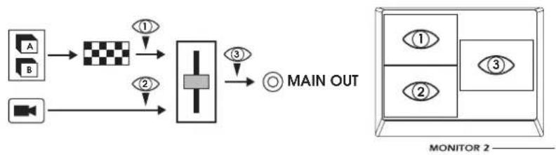
flowchart
graph LR
    A["Input Module A"] --> C["Checkerboard"]
    B["Input Module B"] --> C
    C --> D["Main Out"]
    D --> E["Main Out"]
    style A fill:#f9f,stroke:#333
    style B fill:#f9f,stroke:#333
    style C fill:#ccf,stroke:#333
    style D fill:#cfc,stroke:#333
    style E fill:#fcc,stroke:#333
Routing 12
This applies an effect to an external input source, and mixes it with a bank clip.
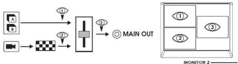
flowchart
graph LR
    A["Input A"] -->|①| C["Central Unit"]
    B["Input B"] -->|②| C
    C -->|③| D["Main OUT"]
    D --> E["Monitor 2"]
Routing 13
This mixes a bank clip with an external input source, and then applies an effect.
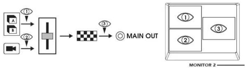
flowchart
graph LR
    A["Input Video"] -->|①| B["Video Display"]
    C["Input Image"] -->|②| B
    B --> D["Main Out"]
    D -->|③| E["Main Out"]
    E --> F["Monitor 2"]
2. Dual Routings
These routings play back two clips simultaneously and mix them.
Routing 21
This applies an effect to a clip from Group A, and then mixes it with a clip from Group B.
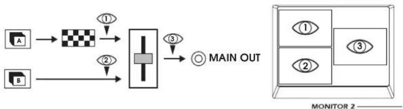
flowchart
graph LR
    A["Input A"] --> C["Checkerboard"]
    B["Input B"] --> C
    C --> D["Central Processing Unit"]
    D --> E["Main OUT"]
    E --> F["Monitor 2"]
    style A fill:#f9f,stroke:#333
    style B fill:#f9f,stroke:#333
    style C fill:#ccf,stroke:#333
    style D fill:#cfc,stroke:#333
    style E fill:#fcc,stroke:#333
Routing 22
This applies an effect to a clip from Group B, and then mixes it with a clip from Group A.
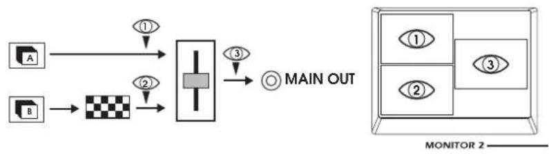
flowchart
graph TD
    A["Input Module A"] -->|①| C["Processing Unit"]
    B["Input Module B"] -->|②| C
    C -->|③| D["Output Monitor 2"]
    D --> E["Main OUT"]
Routing 23
This mixes clips from Group A and Group B, and then applies an effect.
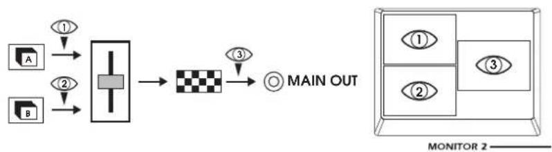
flowchart
graph LR
    A["Input Module A"] --> C["Processing Unit"]
    B["Input Module B"] --> C
    C --> D["Checkerboard"]
    D --> E["Main OUT"]
    E --> F["Monitor 2"]
3. Three-layer Routings
These routings play back two clips and mix them with an external input.
NOTE You can also exchange the B group playback with the external input.
Routing 31
This applies an effect to a clip from Group A, mixes it with a clip from Group B, and then mixes this with an external input. The MAIN OUT is not displayed in MONITOR 2 when using this routing.
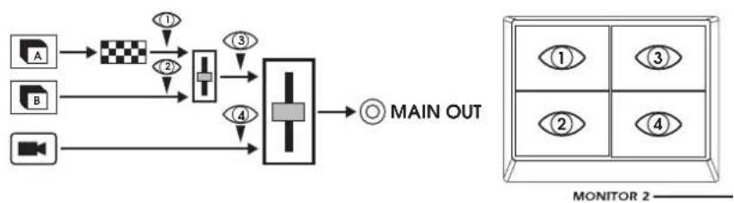
flowchart
graph TD
    A["Sensor A"] --> B["Checkerboard"]
    C["Sensor B"] --> D["Logic Gate"]
    E["Sensor C"] --> F["Main Out"]
    B --> D
    D --> F
    style A fill:#f9f,stroke:#333
    style C fill:#f9f,stroke:#333
    style E fill:#f9f,stroke:#333
    style B fill:#ccf,stroke:#333
    style D fill:#ccf,stroke:#333
    style F fill:#ccf,stroke:#333
Routing 32
This applies an effect to a clip from Group B, mixes it with a clip from Group A, and then mixes this with an external input. The MAIN OUT is not displayed in MONITOR 2 when using this routing.
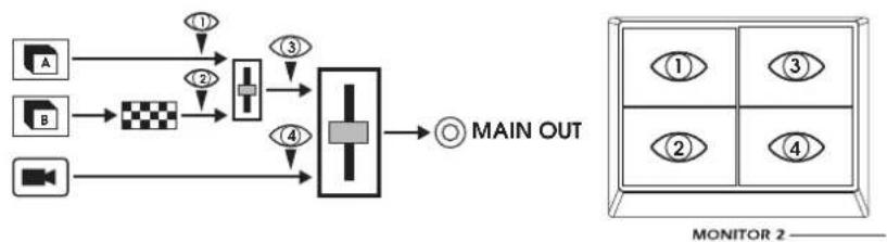
flowchart
graph TD
    A["A"] --> C["1"]
    B["B"] --> D["2"]
    C --> E["3"]
    D --> F["4"]
    E --> G["MAIN OUT"]
    F --> G
    G --> H["MONITOR 2"]
Routing 33
This mixes clips from Group A and Group B, applies an effect, and then mixes this with an external input. The MAIN OUT is not displayed in MONITOR 2 when using this routing.
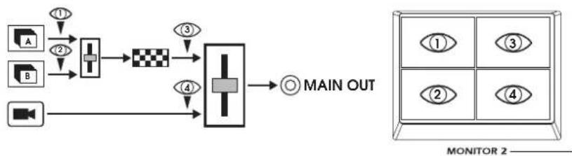
flowchart
graph LR
    A["Input Device A"] -->|①| B["Processing Unit"]
    C["Input Device B"] -->|②| B
    B --> D["Checkerboard"]
    D --> E["Main Out"]
    F["Monitor 2"] --> G["Output"]
    style A fill:#f9f,stroke:#333
    style C fill:#f9f,stroke:#333
    style F fill:#ccf,stroke:#333
    style G fill:#cff,stroke:#333
Routing 34
This applies an effect to the external input, and mixes this with the combination of clips A and B. The MAIN OUT is not displayed in MONITOR 2 when using this routing.
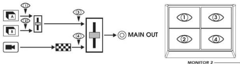
flowchart
graph TD
    A["Input Device A"] -->|①| Processing
    B["Input Device B"] -->|②| Processing
    Processing -->|③| MainOutput
    Processing -->|④| MainOutput
    MainOutput --> O["Main OUT"]
    O --> Monitor2["Monitor 2"]
Routing 35
This mixes clips A and B, mixes this with the external input, and then applies an effect.
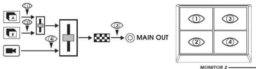
flowchart
graph TD
    A["Input A"] -->|①| B["Process Unit"]
    C["Input B"] -->|②| B
    D["Input C"] -->|④| B
    B --> E["Main Out"]
    E --> F["Checkered Box"]
    F --> G["Main Out"]
4. Separate output Routings
Use these routings when you've connected MONITOR OUT 2 as an independent output connector to a device such as the KPE1. These routings give you two separate outputs; MAIN OUT and MONITOR OUT 2.
Routing 41
MONITOR OUT 2 will simply output the clip from Group B. The clip from Group A will be processed by the effect, mixed with the external input, and sent from MAIN OUT.
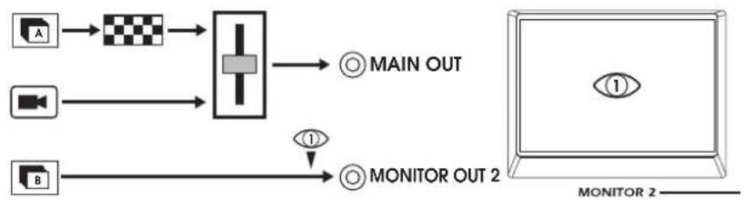
flowchart
graph LR
    A["Input Device A"] --> C["Checkerboard"]
    B["Input Device B"] --> D["Central Processing Unit"]
    C --> D
    D --> E["Main OUT"]
    D --> F["Monitor OUT 2"]
    F --> G["Monitor 2"]
Routing 42
MONITOR OUT 2 will simply output the clip from Group B. The external input will be processed by the effect, mixed with the clip from Group A, and sent from MAIN OUT.
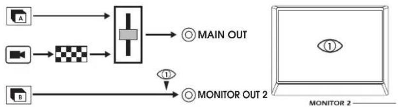
flowchart
graph LR
    A["Input Device A"] --> C["Processing Unit"]
    B["Input Device B"] --> C
    C --> D["Main OUT"]
    C --> E["Monitor OUT 2"]
    E --> F["Output View 1"]
    E --> G["Output View 2"]
Routing 43
MONITOR OUT 2 will simply output the clip from Group B. The Group A clip will be mixed with the external input, then processed by the effect, and sent from MAIN OUT.
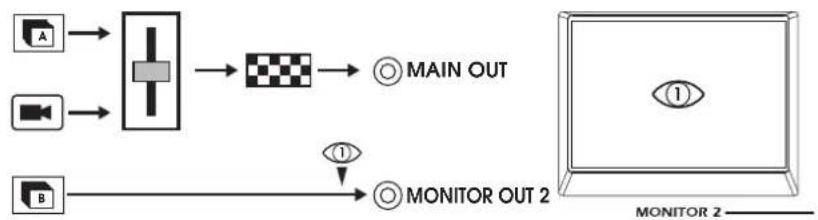
flowchart
graph LR
    A["Input Device A"] --> C["Checkerboard"]
    B["Input Device B"] --> C
    C --> D["MAIN OUT"]
    D --> E["MONITOR OUT 2"]
    E --> F["MONITOR 2"]
Routing 44
MONITOR OUT 2 will output the clip from Group B processed by the effect. The Group A clip will be mixed with the external input, and sent from MAIN OUT.
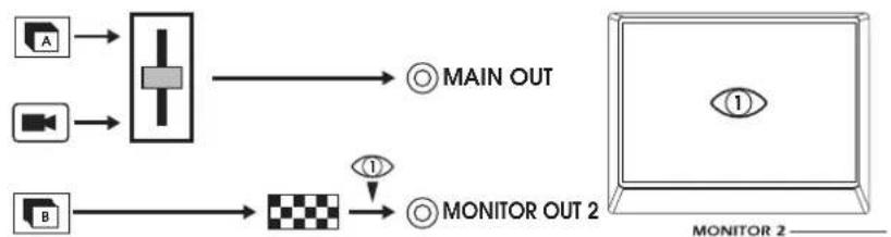
flowchart
graph LR
    A["Input A"] --> Process1["Process Box"]
    B["Input B"] --> Process2["Process Box"]
    Process1 --> MainOUT["Main OUT"]
    Process2 --> MONITOROUT2["MONITOR OUT 2"]
    MainOUT --> MONITOROUT2
    MONITOROUT2 --> MONITOROUT2
Transition list
CLIP Effective range of the controller
A
B
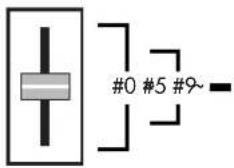
Parameter A2 (A5) = 00: Fade
Parameter Function Values
A3 (A6) Selects the controller for the Fade effect. A1-H4; Fixed value: 00-99
A4 (A7) Sets the effective range of the controller (00–99). If a controller value (A1–H4) is selected, this controller will determine the range of the controller set by A3.
Parameter A2 (A5) = 01: Wipe 1
Parameter Function Values
A3 (A6) Selects the controller for the Wipe effect. A1–H4, Fixed value: 00–99:
A4 (A7) 00–99: Selects the transition type (1st digit) and the controller range (2nd digit).
A1-H4: If a controller value is selected, this controller will determine the range of the controller set by parameter A3.
NOTE These values are identical for 01: Wipe 1; 02: Wipe 2; and 03: Wipe 3
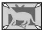
00 (\~09)
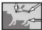
10 (\~19)
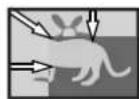
20 (\~29)
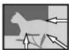
30 (\~39)
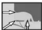
40 (\~49)
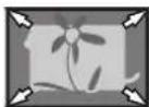
50 (\~59)
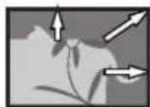
60 (\~69)
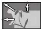
70 (\~79)
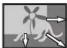
80 (\~89)
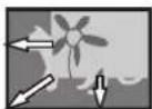
90 (\~99)
Parameter A2 (A5) = 02: Wipe 2
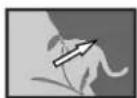
00 (\~09)
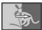
10 (\~19)
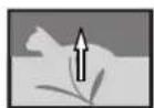
20 (\~29)
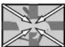
30 (\~39)
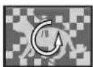
40 (\~49)
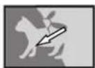
50 (\~59)
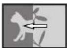
60 (\~69)
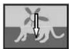
70 (\~79)

80 (\~89)
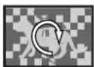
90 (\~99)
Parameter A2 (A5) = 03: Wipe 3
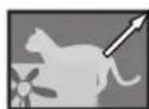
00 (\~09)
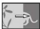
10 (\~19)
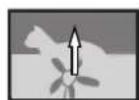
20 (\~29)
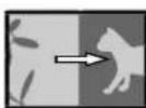
30 (\~39)
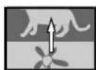
40 (\~49)
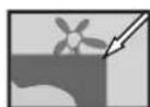
50 (\~59)
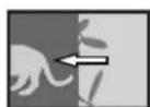
60 (\~69)
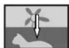
70 (\~79)
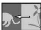
80 (\~89)
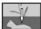
90 (\~99)
Effect list
| Edit No. B2 B3 B4 | |||
| Function Effect switch | |||
| Value 00 (-49) :(50-) 99: | DisabledEnabled 1 | 00 (-49) : DisabledEnabl(50-2) 99: | 00: Enabled 1 or Enabled 2Enabled 1 and Enabled 2 |
| Fixed value d1: HOLD C1: TOUCH 00 (or) | |||
| Edit No. B5 B6 B7 | |||||||
| No. TitleB1 | Function | Fixed value | Function | Fixed value | Function | Fixed value | |
| Effect | Effect | Effect | |||||
| 00 | Invert top/bottom | Mix | G1: RIBBON | ||||
| 00: effect0%-99: effect100% | |||||||
| 01 | Invert left/right | Mix | G1: RIBBON | ||||
| 00: effect0%-99: effect100% | |||||||
| 02 | Rotate 180 degrees | Mix | G1: RIBBON | ||||
| 00: effect0%-99: effect100% | |||||||
| 03 | Exciter | Mix | G1: RIBBON | ||||
| 00: effect0%-99: effect100% | |||||||
| 04 | Negative | Mix | G1: RIBBON | ||||
| 00: effect0%-99: effect100% | |||||||
| 05 | Color Change | Mix | G1: RIBBON | -/+ | 85 | ||
| 00: effect0%-99: effect100% | 00: -180degrees-99: +180degrees | ||||||
| 06 | RGB Separation | Mix | G1: RIBBON | -/+ | 85 | ||
| 00: effect0%-99: effect100% | 00: RGB-99: BGR | ||||||
| 07 | Emboss | Mix | G1: RIBBON | Depth | 85 | ||
| 00: effect0%-99: effect100% | 00: Inner-99: Outer | ||||||
| 08 | Brightness | Mix | G1: RIBBON | -/+ | 85 | ||
| 00: effect0%-99: effect100% | 00: Darkest-99: Brightness | ||||||
| 09 | Contrast | Mix | G1: RIBBON | -/+ | 85 | ||
| 00: effect0%-99: effect100% | 00: min-99: max | ||||||
| 10 | Feedback | Mix | G1: RIBBON | Depth | 85 | ||
| 00: effect0%-99: effect100% | 00: 0%-99: 90% | ||||||
| 11 | Blur | Mix | G1: RIBBON | Depth | 85 | ||
| 00: effect0%-99: effect100% | 00: 50%-99: 98% | ||||||
| 12 | Monotone | Mix | G1: RIBBON | color | 85 | Depth | 85 |
| 00: effect0%-99: effect100% | 00: -180degrees-99: +180degrees | 00: black and white-99: color | |||||
| 13 | Line drawing | Mix | G1: RIBBON | Threshold | 50 | -/+ | 85 |
| 00: effect0%-99: effect100% | 00: min-99: max | 00: White line-99: Black line | |||||
| 14 | Binarize | Mix | G1: RIBBON | Threshold | 50 | -/+ | 85 |
| 00: effect0%-99: effect100% | 00: min-99: max | 00: Black-99: White | |||||
| 15 | Through | --- | G1: RIBBON | --- | 85 | --- | 85 |
| --- | --- | --- | |||||
| Edit No. d2 d3 d4 | |||
| Function | Effect switch | ||
| value(50 - ) 99: | 00 (-49) : DisabledEnabled1 (50 - ) 99: | 00 (-49) : DisabledEnabled 2 | 00: Enabled 1 or Enabled 299: Enabled 1 and Enabled 2 |
| Standard value | d1: HOLD | C1: TOUCH | 00 (or) |
| Edit No. d5 | d6 | |||||
| No. Title d1 | Function | Standard value | Function | Standard value | ||
| Effect | Effect | Notes | ||||
| 00 | Scratch | Scratch | G1: RIBBON | Maximum | 50 | Specify d3 and d5 as the pair C1: TOUCH and G1: RIBBON. |
| -: Reverse - +: Forward | 00: 1sec. - 99: 8sec. | |||||
| 01 | Reverse:Still:Forward | Speed | G1: RIBBON | Maximum | 50 | |
| 00: Reverse - 50: Still - 99: Forward | 00: x1 - 99: x8 | |||||
| 02 | Still:Forward | Speed | G1: RIBBON | Maximum | 50 | |
| 00: Still - 99: Forward | 00: x1 - 99: x8 | |||||
| 03 | Reverse:Still | Speed | G1: RIBBON | Maximum | 50 | |
| 00: Reverse - 99: Still | 00: x1 - 99: x8 | |||||
| 04 | x1:Forward | Speed | G1: RIBBON | Maximum | 50 | |
| 00: x1 - 99: Forward | 00: x2 - 99: x8 | |||||
| 05 | Reverse:x1 | Speed | G1: RIBBON | Maximum | 50 | |
| 00: Reverse - 99: x1 | 00: x2 - 99: x8 | |||||
Clip parameter list
Playback Type and Playback Pattern selection
In Clip Edit mode you can choose a playback type and pattern; set the Start, End, Loop and Index Points; and specify the BPM value. The Start Point will always be the location from which playback begins, and the End Point will always be where playback either ends, or returns to the Loop point. In Type 1 and Type 2, the Start Point is used as the Loop Point; In Types 3 and 4 you are free to set an independent Loop Point. The Index point is used to select the single frame that will represent the clip when displayed in Bank mode.
When you hold down the EDIT key and press the clip key for the clip you want to edit, the first thing to appear in the VALUE display will be "T.#. - #." The first value (T.1.-T.4) specifies how the playback type, and the second value (-#) specifies the playback pattern.
NOTE Once you've specified the playback type, you won't be able to change this setting unless you exit Clip Edit mode, and begin editing again.
NOTE If you press the Play key while performing clip editing, playback will occur between the Start Point and End Point you specified. You are free to specify an Index Point that is outside the range of the Start/End Points.
Type 1: Specified End Point
Patterns of this type will play or loop between the Start Point and End Point. This is the most basic type of pattern.
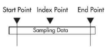
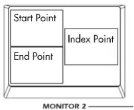
Pattern 1: Normal Loop
Start Point End Point
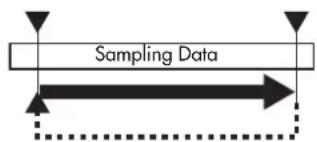
This pattern plays from the Start Point to the End Point, then returns to the Start Point and continues to play repeatedly.
Pattern 2: Alternating Loop
Start Point End Point
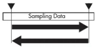
flowchart
graph TD
    A["Sampling Data"] --> B["Arrow Right"]
    A --> C["Arrow Left"]
    A --> D["Arrow Up"]
    A --> E["Arrow Down"]
This pattern plays from the Start Point to the End Point, then plays backward toward the Start Point, and continues repeating this action.
Pattern 3: One-Shot
Start Point End Point
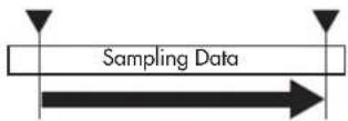
This pattern plays from the Start Point to the End Point only once, and then stops (freezes) at the End Point.
Pattern 4: Reverse Normal Loop
Start PointEnd Point This pattern is similar to Pattern 1, except the data is
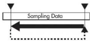
played in reverse. Pattern 4 plays from the Start Point to the End Point, then returns to the Start Point and continues to play repeatedly.
Pattern 5: Reverse Alternating Loop
End Point Start Point
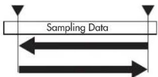
This pattern is similar to Pattern 2, except the data is played in reverse. This pattern plays from the Start Point to the End Point, then plays back toward the Start Point, and continues repeating this action.
Pattern 6: Reverse One-Shot
End Point Start Point
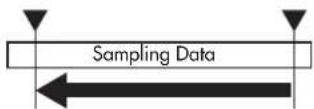
This pattern is similar to Pattern 3, except the data is played in reverse. This pattern plays from the Start Point to the End Point only once, and then stops (freezes) at the End Point.
Type 2: Tempo and Beat Specified End Point
Patterns of this type let you specify the End Point in terms of BPM and a number of beats (Eb), and are appropriate when you want to synchronize video with music.
For example if you specify the BPM as 120 and the End Beat (number of beats: Eb) value as 8, the End Point will be automatically be placed four seconds (when playing at BPM=120) later than the Start Point. If you select a style in which the clip playback speed is synchronized to the BPM, and enter the appropriate BPM value, the video loop will play back in synchronization to the beat. The playback patterns are the same as for Type 1.
If you change the Start Point, you'll need to once again set the BPM value and End Beat setting to re-specify the End Point.
Type 3: Specified Loop Point and End Point
Patterns of this type allow you to specify a Loop Point separately from the Start Point and End Point. Playback will loop from this Loop Point.
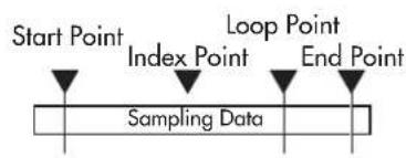
flowchart
graph LR
    A["Start Point"] --> B["Index Point"]
    B --> C["Loop Point"]
    C --> D["End Point"]
    D --> E["Sampling Data"]
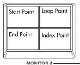
Pattern 1: Normal
Start Point End PointLoop Point
flowchart
graph TD
    A["Input"] --> B{Sampling Data}
    B --> C["Output"]
    style A fill:#f9f,stroke:#333
    style B fill:#ccf,stroke:#333
    style C fill:#cfc,stroke:#333
This pattern plays once from the Start Point to the End Point, and then plays back repeatedly from the Loop Point.
Pattern 2: Alternating Loop
Start Point End PointLoop Point
flowchart
graph TD
    A["Input"] --> B{Sampling Data}
    B --> C["Process"]
    C --> D["Output"]
    style A fill:#f9f,stroke:#333
    style D fill:#bbf,stroke:#333
This pattern plays once to the End Point, and then continues playing alternately forward and backward between the Loop Point and End Point.
Pattern 3: Reverse Normal Loop
End Point Start PointLoop Point
flowchart
graph TD
    A["Sampling Data"] --> B["Process Block"]
    B --> C["Output 1"]
    B --> D["Output 2"]
    B --> E["Output 3"]
    B --> F["Output 4"]
This pattern is similar to Pattern 1, except the data is played in reverse. This pattern plays once from the Start Point to the End Point, and then plays back repeatedly from the Loop Point to the End Point.
Pattern 4: Reverse Alternating Loop
End Point Start PointLoop Point
flowchart
graph TD
    A["Sampling Data"] --> B["Process Block"]
    B --> C["Output 1"]
    B --> D["Output 2"]
    B --> E["Output 3"]
    B --> F["Output 4"]
This pattern is similar to Pattern 2, except the data is played in reverse. This pattern plays once to the End Point, and then continues playing alternately forward and backward between the Loop Point and End Point.
Type 4: Tempo and Beat Specified Loop Point and End Point
Patterns of this type are based on Type 3 which allows you to specify a Loop Point, but differ in that you can specify the Loop Point and End Point in terms of BPM and number of beats (Eb). When you specify the BPM and the number of beats (Eb), the End Point will automatically be set to the appropriate time (when playing at that BPM) from the Loop Point. If you select a style in which the clip playback speed is synchronized to the BPM, and enter the appropriate BPM value, the video loop will play back in synchronization to the beat. The playback patterns are the same as for Type 3.
If you change the Start Point, you'll need to once again set the BPM value and End Beat setting to re-specify the End Point.
Appendix
Tips for working with the kaptivator
1. Using BPM to control the video playback speed
By using the appropriate BPM setting of a clip together with a BPM-synchronized style, you can make the video playback speed vary according to the BPM.
→ With the factory preset styles, style 00 is set to synchronize the video playback speed to the BPM. Choose style 00, and while you play back the desired clip, tap the TAP/BPM key in a varying tempo. Notice that the video playback speed will change.
(1) Specifying the BPM value for normal playback
For each clip, specify the BPM value at which the video will play at normal speed. You can set this BPM value to the tempo of the movement in the video.
1 Hold down the EDIT key and press the clip pad for which you want to specify the BPM.
2 P r ess the EDIT key several times to access the BPM value parameter.
3 Press the ▶II key to play back the clip normally. Tap the TAP/BPM key in time with the video to specify the BPM value. Alternatively, you can use the VALUE knob to specify the BPM value.
4 P r ess the YES/WRITE key to save the clip settings you edited.
NOTE With the factory settings, the BPM value of all clips is set to "120."
(2) Creating a BPM-synchronized playback style
1 Select the style that you want to edit.
2 Hold down the EDIT key and press the STYLE key.
3 Press the EDIT key several times to select parameter C3. (C3 is the parameter that specifies the normal speed for Group A)
4 Use the VALUE knob to set the value to "r2" so that BPM-synchronized playback will occur. If you also want to perform BPM-synchronized playback for Group B, press the EDIT several times to select the parameter E3, and use the VALUE knob to set the value to "r2."
5 P r ess the YES/WRITE key to save your changes and exit Style Edit.
(3) Playing in sync with the BPM
1 Select the BPM-synchronized style you edited.
2 Specify a BPM value and play back the clip.
3 T ap the TAP/BPM key in time with the music.
4 The video playback speed will change in sync with the BPM value.
2. Using the kaptivator with your computer
If you want to use your computer to capture the video from the kaptivator, or use the kaptivator to sample original video material from your computer, you can connect the kaptivator's DV connector to your computer's IEEE 1394 connector and enjoy an even wider range of possibilities.
Sending the kaptivator's main video output to your computer
1 Turn on the kaptivator and set the DV connector setting to "out." (p.9)
2 Start up your computer.
3 Connect the kaptivator's DV port to your computer.
4 M make sure that the connection has been detected by your computer.
5 Start up your video editing application program on your computer.
6 Begin playback on the kaptivator, and simultaneously start capturing on your video editing application.
Sampling video from your computer into the kaptivator
1 Turn on the kaptivator and set the DV connector setting to "in." (sp.9)
2 Start up your computer.
3 Connect your computer to the kaptivator's DV port.
4 M make sure that the connection has been detected by your computer.
5 Start up your video editing application program on your computer.
6 In your video editing application, prepare the video material that you want to send.
7 Set MONITOR 2 on the kaptivator to DV, and begin trial playback via the DV connection to verify that the kaptivator is receiving the video.
8 Begin sampling on the kaptivator, and immediately start sending the video from your computer.
You'll have to manually execute playback and sampling on the kaptivator.
NOTE The kaptivator does not support the AV/C commands that automatically control typical DV devices such as digital video cameras. This means that depending on the application software you're using on your computer, error messages may appear in response to operation commands that the kaptivator does not support (such as REC/STOP).
NOTE For details on how to operate your video editing application software, contact the manufacturer of your software.
3. Managing data on the hard drive
You can make efficient use of the internal hard drive's recording capacity by taking advantage of the clip copy and clip edit functions.
The video material that is sampled into the kaptivator is stored in minimum units of approximately 8 seconds.
For example if you sample four segments of video, which are respectively (a) 3 seconds, (b) 4 seconds, (c) 5 seconds, and (d) 10 seconds long (totaling 22 seconds), the video material used by these four clips (if sampled individually) would actually occupy (a) 8 seconds, (b) 8 seconds, (c) 8 seconds, and (d) 16 seconds (totaling 40 seconds) of space on the hard disk. If you used your video editing software etc. to connect these four segments of video into a single segment with a few blank frames between them, and sample it as a single clip, this would occupy only 24 seconds of space on the hard disk. Then you would simply copy this 24-second clip to make four clones, and use clip editing to specify the appropriate playback points for each clip so that they would play back just as if you had sampled them separately.
4. Using MIDI to work with clips
What is MIDI?
MIDI stands for Musical Instrument Digital Interface, and is a world-wide standard for transferring a wide variety of performance-related information between electronic musical instruments and computers.
MIDI connections
Use commercially available MIDI cables to send and receive MIDI messages. Connect the kaptivator's MIDI connectors to the MIDI connectors of the external MIDI device.
MIDI IN connector: Receives MIDI messages from another MIDI device. Connect this to the MIDI OUT connector of your external device.
MIDI OUT connector: Transmits MIDI messages from the kaptivator. Connect this to the MIDI IN connector of your external device.
MIDI output when you press a Clip Pad
The following note numbers are assigned to the clip pads. The corresponding Note-on message is transmitted when you press a clip pad.
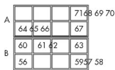
Using a MIDI keyboard to play clips
You can use Note messages sent from a MIDI keyboard connected to the MIDI IN connector not only to play back the clips selected for the clip pad, but also to play back as many clips as there are keys on your keyboard, without having to switch banks.
How Note messages correspond to Clips
Upper (note numbers: 64–127)
The clips of the eight banks assigned to clip pad Group A (64 clips) are assigned to note numbers 64 through 127 in ascending order.
Lower (note numbers: 0–63)
The clips of the eight banks assigned to clip pad Group B (64 clips) are assigned to note numbers 63 through 0 in descending order.
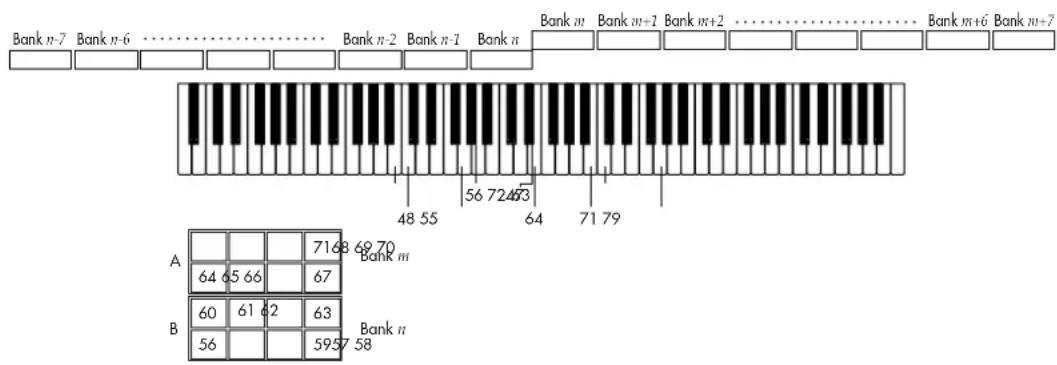
Trobleshooting
Power does not turn on.
☐ Is the AC adapter connected?
☐ Is the AC adapter connected to an AC outlet?
The image from the connected device is not input.
☐ Is the cable correctly connected to the connector?
☐ Is your external device powered-on, and is it set correctly?
☐ Have you chosen the correct input setting for the kaptivator?
Image does not appear in the monitor.
☐ Is the external device powered-on, and it is set correctly?
☐ Have you chosen the correct input setting for the kaptivator?
☐ Is MONITOR SELECT set correctly?
☐ If there is a problem with the display, try adjusting the monitor. (p.12)
Clip does not play back.
☐ Is the style setting correct?
☐ Could you have selected a style in which playback is synchronized to an audio trigger, or in which the ribbon controller adjusts the playback speed?
Can't delete or edit a clip.
☐ Could the clip protect setting be "On"? (sp.24)
□ Is a motion sequence running? (p.17)
Can't control via MIDI.
☐ Is the MIDI cable connected correctly?
☐ Have you made settings so that the Kaptivator is transmitting and receiving MIDI data on the same MIDI channel as the external device?
☐ Is the MIDI channel set correctly? (p.27)
Preset Style list
Style numbers: 00–39 Demo styles (ideas for style settings).
Style numbers: 40–54 Routing variations. Variations of video effects.
Style numbers: 55–84 Wipe variations. Variations of video effects.
Style number: 85 Use the FX control knob to change the dissolve time.
Use the ribbon to change the playback speed.
Group A has smoothing; Group B has no smoothing.
Style number: 86 Use the FX control knob to change the dissolve time.
Use BPM to change the playback speed.
Style numbers: 87–91 Clip Start variations.
Style numbers: 92–97 Time Effect variations.
Use the ribbon to control the playback speed.
Specifications
Video sampling rate: 13.5 MHz, 4:2:2 8-bit
Input/output connectors: VIDEO INPUT 1: Composite
VIDEO INPUT 2: S-Video
AUDIO TRIG INPUT (L, R): RCA connector
MAIN OUT: Composite, S-Video (one each)
MONITOR OUT 1: Composite
MONITOR OUT 2: Composite
PHONES: Stereo 1/4"
DV I/O (digital Video input/output)
MIDI: MIDI IN, MIDI OUT
DC 12V IN
Storage device: 40 GB hard disk
Power supply: DC 12V (dedicated AC adapter)
Dimensions: 310 (W) x 249 (D) x 99 (H) mm
12.20 (W) × 9.80 (D) × 3.90 (H) inches
Weight: 2.8 kg / 6.171 lbs.
Included items: Dedicated AC adapter
* Appearance and specifications are subject to change without notice.
目次
はじめに....52
flowchart
graph TD
    A[" DVD PLAYER "] --> B[" CAMCORDER "]
    B --> C[" DJ Set "]
    C --> D[" Headphones "]
    D --> E[" PHONES "]
    E --> F[" DV I/O "]
    F --> G[" HDMI IN/OUT "]
    G --> H[" DC12V "]
    H --> I[" TV MONITOR "]
    I --> J[" MIDI sequencer MIDI OUT/N "]
    J --> K[" AC ADAPTER "]
    K --> L[" DVcamera, DVrecorder etc. IEEE1394 "]
DV端子の入出力設定
![** UTILITY MODE ** MIDI setting 2/2 Bank A CC#16 Bank B CC#17 Style(Pr)Enable Style FX CC#80 Pad(Note)Enable Clock Disable ↓: [EDIT] →: [YES]](/content/2026/05/1002548/images/08ce146a7f886033efbd3267a936cacb686699f34a8d4d454467539dcaae63bd.jpg)
4. Separate Output Routing
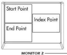
パターン 1
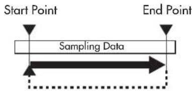
パターン 5
End Point Start Point
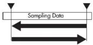
End Point Start Point
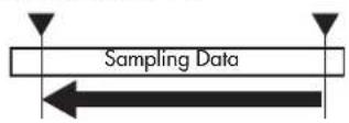
パターン 1
Start Point Loop Point End Point
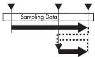
flowchart
graph TD
    A["Start"] --> B{Sampling Data}
    B --> C["Process Step 1"]
    B --> D["Process Step 2"]
    C --> E["Output"]
    D --> E
    style A fill:#f9f,stroke:#333
    style E fill:#bbf,stroke:#333
Start Point End PointLoop Point
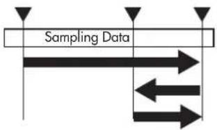
flowchart
graph TD
    A["Start"] --> B{Sampling Data}
    B --> C["Process Step 1"]
    B --> D["Process Step 2"]
    C --> E["Output"]
    D --> E
    style A fill:#f9f,stroke:#333
    style E fill:#bbf,stroke:#333
パターン 3
End Point Start PointLoop Point
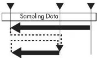
flowchart
graph TD
    A["Input"] --> B["Sampling Data"]
    B --> C["Output 1"]
    B --> D["Output 2"]
    B --> E["Output 3"]
    B --> F["Output 4"]
    style A fill:#f9f,stroke:#333
    style B fill:#ccf,stroke:#333
    style C fill:#cfc,stroke:#333
    style D fill:#fcc,stroke:#333
    style E fill:#cff,stroke:#333
    style F fill:#ffc,stroke:#333
パターン 4
End Point Start PointLoop Point
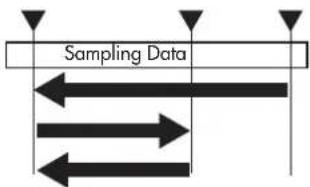
flowchart
graph TD
    A["Sampling Data"] --> B["Process Block"]
    B --> C["Output 1"]
    B --> D["Output 2"]
    B --> E["Output 3"]
ENA = A : Transmit when Note On/Off Enable.
C : Transmit when Control Change Enable.
P : Transmit when Program Change Enable.
nn : MIDI Channel No,(0\~15) Usually Global Channel.
kk : Note Number (48\~71)
cc : Control Number (1\~31, 64\~95)
| Status[Hex] | Description ( Transmitted when ... ) |
| F8 | Timing Clock ( Clock Out ) |
| FE | Active Sensing ( Always ) |
1-3 UNIVERSAL SYSTEM EXCLUSIVE MESSAGES (DEVICE INQUIRY REPLAY)
| Byte [Hex] | Description | |
| P0 | Exclusive Status | |
| 75 | Non Realtime Message | |
| On | MIDI Channel Number (Device ID) | |
| 06 | Inquiry Message (Sub ID 1) | |
| 02 | Identity Reply (Sub ID 2) | |
| 42 | KORG ID (Manufactures ID) | |
| 77 | KTV1 ID (Family ID (LSB)) | |
| 00 | ( (MSB)) | |
| 00 | (Member ID (LSB)) | |
| 00 | ( (MSB)) | |
| ** | ROM No, 1~ | (Minor Ver.(LSB)) |
| 00 | ( (MSB)) | |
| ** | Soft Version | (Major Ver.(LSB)) |
| 00 | ( (MSB)) | |
| F7 | EOX | |
This message is transmitted whenever a INQUIRY MESSAGE REQUEST is received.
1-4 STRUCTURE OF SYSTEM EXCLUSIVE MESSAGES
| 1st Byte = 1111 0000 (F0) : Exclusive Status + | |
| 2nd Byte = 0100 0010 (42) : XCRG ID Ex.Header | |
| 3rd Byte = 0011 nnnn (3n) : Format ID n:MIDI Channel | |
| 4th Byte = 0111 0111 (77) : KTVI ID -+ | |
| 5th Byte = 0fff fffff (ff) : Function Code | |
| 6th Byte = 0ddd dddd (dd) : Data | |
| : : : | |
| LastByte = 1111 0111 (F7) : End of Exclusive |
1-5 SYSTEM EXCLUSIVE MESSAGES FUNCTION CODE LIST (TRANSMIT)
| Function ID [Hex] | Description | R | E |
| 51 | Global Data Dump | o | |
| 65 | All Style Data Dump | o | |
| 79 | 1 Motion Sequence Data Dump | o | |
| 78 | 10 Motion Sequence Data Dump | o | |
| 23 | Data Process (Load) Completed | o | |
| 24 | Data Process (Load) Error | o |
Transmitted when
R : Request message is received and data dump from MIDI dump page.
E : Exclusive message received.
- RECOGNIZED RECEIVE DATA
2-1 CHANNEL MESSAGE
| Status [E:ex] | Second [H] [D] | Third [J] [D] | Description | ENA |
| 8n | kk (kk) | vv (vv) | Note Off | A |
| 9n | kk (kk) | 00 (00) | Note off | A |
| 9n | kk (kk) | vv (vv) | Note On | A |
| Bn | cc (cc) | dd (dd) | Control Change | C |
| On | pp (pp) | -- -- | Program Change | P |
| En | bb (bb) | bb (bb) | Bender Change | C |
ENA - A : Recognized when Note On/Off Enable
C : Recognized when Control Change Enable
P : Recognized when Program Change Enable
nn : MIDI Channel No, (0-15) Usually Global Channel.
kk : Note Number (48-71)
vv : Verocity will be ignored
cc : Control Number (1\~31, 64\~95)
| Status[Hex] | Description ( Recognized when ... ) |
| F8 | Timing Clock ( Clock Ext.In ) |
| F2 | Active Sensing ( Always ) |
2-3 UNIVERSAL SYSTEM EXCLUSIVE MESSAGE (DEVICE IMQUIRY REQUEST)
| Byte [Hex] | Description |
| F0 | Exclusive Status |
| 7E | Non Realtime Message |
| nn | MIDI Channel Number {Device ID} |
| 06 | Inquiry Message {Sub ID 1} |
| 01 | Identity Request {Sub ID 2} |
| F7 | BOX |
When receive this message and transmits Inquiry Reply Message.
nn = 00\~0F : Receive if same Channel
IF : Receive any Channel
2-4 SYSTEM EXCLUSIVE MESSAGE FUNCTION CODE LIST (RECEIVE)
| Function ID [Hex] | Description |
| OE | Global Data Dump Request |
| 31 | All Style Data Dump Request |
| 78 | 1 Motion Sequence Data Dump Request |
| 7A | 10 Motion Sequence Data Dump Request |
| 51 | Global Data Dump |
| 65 | All Style Data Dump |
| 79 | 1 Motion Sequence Data Dump |
| 7B | 10 Motion Sequence Data Dump |
Recognized only on the MIDI dump page.
- MIDI EXCLUSIVE FORMAT (R:Receive, T:Transmit)
| (1) GLOBAL DATA DUMP REQUEST | R | |
| Byte [Hex] | Description | |
| F0,42,3n,77 | Exclusive Header KTV1 | |
| 0000 1110 (OE) | Global Data Dump Request | CEh |
| 1111 C111 (F7) | EOX | |
When this message is received at the MIDI dump page, the GLOBAL DATA DUMP (Function:51h) message will be transmitted.
The DATA PROCESS(LOAD) ERROR(Function:24h) message will be transmitted in other cases.
(2) ALL STYLE DATA DUMP REQUEST
| Byte [Hex] | Description |
| P0,42,3n,77 | Exclusive Header KTV1 |
| 0C11 00C1 (31) | All Style Data Dump Request 31h |
| 1111 0111 (F7) | BOX |
When this message is received at the MIDI dump page, the GLOBAL DATA DUMP (Function:65h) message will be transmitted.
The DATA PROCESS(LOAD) ERROR(Function:24h) message will be transmitted in other cases.
(3) 1 MOTION SEQUENCE DATA DUMP REQUEST R
| Byte [Hex] | Description |
| F0,42,3n,77 | Exclusive Header KTV1 |
| 0111 1000 (78) | 1 Motion Sequence Data Dump Request 78h |
| Orrm rrrrm (mm) | Dump Motion Number (mm = 00h-63h) |
| 1111 0111 (F7) | EOX |
When this message is received at the MIDI dump page, the 1 MOTION SEQUENCE DATA DUMP(Function:79h) message will be transmitted. The DATA PROCESS(LOAD) ERROR(Function:24h) message will be transmitted in other cases.
(4) 10 MOTION SEQUENCE DATA DUMP REQUEST R
| Byte [Hex] | Description |
| F0,42,3n,77 | Exclusive Header KTV1 |
| 0111 1010 (7A) | 10 Motion Sequence Data Dump Request 7Ah |
| 0000 pppp (10p) | Dump Motion Page Number (0p = 00h~09h) |
| 1111 0111 (F7) | ECX |
When this message is received at the MIDI dump page, the 10 MOTION SEQUENCE DATA DUMF (Function:78h) message will be transmitted.
The DATA PROCESS(LOAD) ERROR(Function:24h) message will be transmitted in other cases.
(5) GLOBAL DATA DUMP R/T
| Byte [Hex] | Description |
| F0,42,3n,77 | Exclusive Header KTV1 |
| 0101 0001 (51) | Global Data Dump 51h |
| 0ddd dddd (dd) | Data [NOTE1] [TABLE1] |
| : | : |
| 1111 0111 (F7) | ECX |
When this message is received at the MIDI dump page, the DATA PROCESS (LOAD) COMPLETED(Function:23h) message or the DATA PROCESS(LOAD) ERROR (Function:24h) message will be transmitted.
The DATA PROCESS(LOAD) ERROR(Function:24h) message will be transmitted in other cases.
(6) ALL STYLE DATA DUMP R/T
| Byte [Hex] | Description |
| F0,42,3n,77 | Exclusive Header KTV1 |
| 0110 0101 {65} | All Style Data Dump 65h |
| 0ddd dddd {dd} | Data [NOTE2] [TABLE2] |
| : | : |
| 1111 0111 (F7) | EOX |
When this message is received at the MIDI dump page, the DATA PROCESS (LOAD) COMPLETED (Function:23h) message or the DATA PROCESS (LOAD) ERROR (Function:24h) message will be transmitted.
The DATA PROCESS(LOAD) ERROR(Function:24h) message will be transmitted in other cases.
(7) 1 MOTION SEQUENCE DATA DUMP R/T
| Byte [Hex] | Description |
| F0,42,3n,77 | Exclusive Header KTV1 |
| 0111 1001 (79) | 1 Motion Sequence Data Dump 79h |
| 0mm nmm (mm) | Dump Motion Number (mm = 00h~63h) |
| 0ddd dddd (dd) | Data [NOTE3][TABLE3] |
| : | : |
| 1111 0111 (F7) | ECX |
When this message is received at the MIDI dump page, the DATA PROCESS (LOAD) COMPLETED (Function:23h) message or the DATA PROCESS (LOAD) ERROR (Function:24h) message will be transmitted.
The DATA PROCESS(LOAD) ERROR(Function:24h) message will be transmitted in other cases.
(8) 10 MOTION SEQUENCE DATA DUMP R/T
| Byte [Hex] | Description |
| F0,42,3n,77 | Exclusive Header KTV1 |
| 0111 1011 (7B) | 10 Motion Sequence Data Dump 7Ph |
| 0000 pppp (0p) | Dump Motion Page Number (0p = 00h-09h) |
| 0ddd dddd (dd) | Data [NOTE4][TABLE3] |
| : | : |
| 1111 0111 (F7) | EOX |
When this message is received at the MIDI dump page, the DATA PROCESS
(LOAD) COMPLETED(Function:23h) message or the DATA PROCESS(LOAD) ERROR (Function:24h) message will be transmitted.
The DATA PROCESS(LOAD) ERROR(Function:24h) message will be transmitted in other cases.
(9) DATA PROCESS (LOAD) COMPLETED T
| Byte [Hex] | Description |
| F0,42,3n,77 | Exclusive Header KTV1 |
| 0010 0011 (23) | DATA PROCESS(LOAD) COMPLETED 23h |
| 1111 0111 (F7) | SOX |
Transmits this message when DATA LOAD, PROCESSING have been completed.
(10) DATA PROCESS (LOAD) ERROR T
| Byte [Hex] | Description |
| F0,42,3n,77 | Exclusive Header KTV1 |
| 0010 0100 {24} | DATA PROCESS(LOAD) COMPLETED 24h |
| 1111 0111 {F7} | EOX |
Transmits this message when DATA LOAD, PROCESSING have not been completed.
Dump Data Format
$$ n = 0, 1, \dots $$
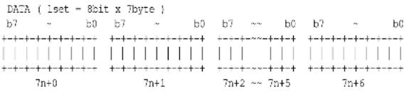
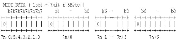
$$ \begin{array}{l} \text {NOTE 1: GROBAL DATA DUMP FORMAT} \ \quad [ \text {Global Data (22byte)} ] \quad (\text {see TABLE 1}) \ \quad 2 2 \text {byte = 7 * 3 + 1 --> 8 * 3 + (1 + 1) = 26byte} \end{array} $$
$$ \begin{array}{l} \text {NOTE 2:ALL STYLE DATA DUMP FORMAT} \ \quad [ \text {Style.00(32byte)],..., [Style.99(32byte)] (see TABLE 2)} \ \quad 3 2 0 0 \text {byte = 7457+1-->8457+(1 + 1) = 3658byte} \end{array} $$
$$ \begin{array}{l} \text {NOTE 3:1 MOTION SEQUENCE DATA DUMP FORMAT} \ \quad [ \text {Motion Data (16 - 200048byte)} ] \quad (\text {see TABLE 3}) \ \quad 1 6 \text {byte = 7 * 2 + 2 --> 8 * 2 + (2 + 1) = 19byte} \ \quad 2 0 0 0 4 8 \text {byte = 7 * 28578 + 2 --> 8 * 28578 + (2 + 1) = 228627byte} \end{array} $$
$$ \begin{array}{l} \text {NOTE 4:10 MOTION SEQUENCE DATA DUMP FORMAT} \ \quad [ \text {Motion Data p0(16 - 200048byte)} ], \ \quad \dots , [ \text {Motion Data p9(16 - 200048byte)} ] \quad (\text {see TABLE 3}) \ 1 6 0 \text {byte} = 7 * 2 2 + 6 \dashrightarrow 8 * 2 2 + (6 + 1) = 1 5 3 \text {byte} \ 2 0 0 0 4 8 0 \text {byte} = 7 * 2 8 5 7 8 2 + 6 \dashrightarrow 8 * 2 8 5 7 8 2 + (6 + 1) = 2 2 8 6 2 6 3 \text {byte} \end{array} $$
$$ \begin{array}{l} \begin{array}{l l l} \text {TABLE 1:} \ + 0 & \text {Monitor 1 Bright} & (\text {valid:0-140}) \ + 1 & \text {Monitor 1 Contrast} & (\text {valid:0-181}) \ + 2 & \text {Monitor 1 Color} & (\text {valid:0-255}) \ + 3 & \text {Monitor 2 Bright} & (\text {valid:0-140}) \ + 4 & \text {Monitor 2 Contrast} & (\text {valid:0-181}) \ + 5 & \text {Monitor 2 Color} & (\text {valid:0-255}) \ + 6 & \text {DV Direction IN/OUT (0 = In, 1 = out)} \ + 7 & \text {Main Out Capture DIS/ENA (0 = Disable, 1 = Enable)} \ + 8 & \text {Power on Style Number (0-99)} \ + 9 & \text {Power on Group A Bank Number (0-99)} \ + 1 0 & \text {Power on Group B Bank Number (0-99)} \ + 1 1 & \text {MIDI Channel (0-15)} \end{array} \ \begin{array}{l} + 1 2 \text { bit7 } \quad \text { MIDI Ribbon Touch [C] ENA / DIS (0 = Enable, 1 = Disable)} \ \text { bit6 - 0 MIDI Ribbon Touch [C] CTRL#} \end{array} \ \begin{array}{l l} + 1 3 \text { bit7 } & \text { MIDI Hold [D] } \ \text { bit6 - C } & \text { MIDI Hold [D] } \end{array} \quad \begin{array}{l l} \text { ENA / DIS (0 - Enable, 1 - Disable) } \ \text { CTRL# } \end{array} \ \begin{array}{l l} + 1 4 \text { bit7 } & \text { MIDI [E] } \ \text { bit6 - 0 MIDI [E] } & \text { ENA / DIS (0 = Enable, 1 = Disable) } \ & \text { CTRL# } \end{array} \ \begin{array}{l l} + 1 5 \text { bit7 } & \text { MIDI Slider [F] } \ \text { bit6 - C } & \text { MIDI Slider [F] } \end{array} \quad \begin{array}{l l} \text { ENA / DIS (0 = Enable, 1 = Disable) } \ \text { CTRL# } \end{array} \ \begin{array}{l l} + 1 6 \text { bit7 } & \text { MIDI Ribbon [G] } \ \text { bit6 - C } & \text { MIDI Ribbon [G] } \end{array} \quad \begin{array}{l l} \text { ENA / DIS (0 - Enable, 1 - Disable) } \ \text { CTRL# } \end{array} \ \begin{array}{l l} + 1 7 \text { bit7 } & \text { MIDI Knob } \quad [ H ] \ \text { bit6 - C } & \text { MIDI Knob } \quad [ H ] \end{array} \qquad \begin{array}{l l} \text { ENA / DIS } (0 = \text { Enable }, 1 = \text { Disable }) \ \text { CTRL# } \end{array} \ \begin{array}{l l} + 1 8 \text { bit7 } & \text { MIDI Group A } \ \text { bit6 - C } & \text { MIDI Group A } \end{array} \quad \begin{array}{l l} \text { ENA / DIS (0 = Enable, 1 = Disable) } \ \text { CTRL# } \end{array} \ \begin{array}{l l} + 1 9 \text { bit7 } & \text { MIDI Group B } \ \text { bit6 - C } & \text { MIDI Group B } \end{array} \quad \begin{array}{l l} \text { ENA / DIS (0 - Enable, 1 - Disable) } \ \text { CTRL# } \end{array} \ \end{array} $$
$$ \begin{array}{l} \begin{array}{l l} + 1 3 \text { bit7 } & \text { MIDI Hold [D] } \ \text { bit6 - C } & \text { MIDI Hold [D] } \end{array} \quad \begin{array}{l l} \text { ENA / DIS (0 - Enable, 1 - Disable) } \ \text { CTRL# } \end{array} \ \begin{array}{l l} + 1 4 \text { bit7 } & \text { MIDI [E] } \ \text { bit6 - 0 MIDI [E] } & \text { ENA / DIS (0 = Enable, 1 = Disable) } \ & \text { CTRL# } \end{array} \ \begin{array}{l l} + 1 5 \text { bit7 } & \text { MIDI Slider [F] } \ \text { bit6 - C } & \text { MIDI Slider [F] } \end{array} \quad \begin{array}{l l} \text { ENA / DIS (0 = Enable, 1 = Disable) } \ \text { CTRL# } \end{array} \ \begin{array}{l l} + 1 6 \text { bit7 } & \text { MIDI Ribbon [G] } \ \text { bit6 - C } & \text { MIDI Ribbon [G] } \end{array} \quad \begin{array}{l l} \text { ENA / DIS (0 - Enable, 1 - Disable) } \ \text { CTRL# } \end{array} \ \begin{array}{l l} + 1 7 \text { bit7 } & \text { MIDI Knob } \quad [ H ] \ \text { bit6 - C } & \text { MIDI Knob } \quad [ H ] \end{array} \qquad \begin{array}{l l} \text { ENA / DIS } (0 = \text { Enable }, 1 = \text { Disable }) \ \text { CTRL# } \end{array} \ \begin{array}{l l} + 1 8 \text { bit7 } & \text { MIDI Group A } \ \text { bit6 - C } & \text { MIDI Group A } \end{array} \quad \begin{array}{l l} \text { ENA / DIS (0 = Enable, 1 = Disable) } \ \text { CTRL# } \end{array} \ \begin{array}{l l} + 1 9 \text { bit7 } & \text { MIDI Group B } \ \text { bit6 - C } & \text { MIDI Group B } \end{array} \quad \begin{array}{l l} \text { ENA / DIS (0 - Enable, 1 - Disable) } \ \text { CTRL# } \end{array} \ \end{array} $$
| +20 bit7 | MIDI Style Px | ENA/DIS (0=Enable, 1=Disable) |
| bit6-0 | MIDI Style Px | CTRL# |
| +21 bit7-4 | (reserved) | |
| bit3-2 | MIDI Clock | Cut/Ext.In/DIS (01=Ext.In, 10=Out, 11=Disable) |
| bit1 | MIDI Note | ENA/DIS (0=Enable, 1=Disable) |
| bit0 | MIDI Program Change | ENA/DIS (0=Enable, 1=Disable) |
CTRL#
| 1~31,64~95:CTRL# 1~31,64~95 |
| 96:Pitch Bender |
TABLE 2 :
| +0 | bit7-6 | Transition Type Sub | 0~3 | |
| bit5-4 | Transition Type Main | 0~3 | ||
| bit3-0 | Rule Type | 0~14 | ||
| +1 | Main Transition Controller | CONT# | ||
| +2 | Main Transition Range/Type | 0~99 | ||
| +3 | Sub Transition Controller | CONT# | ||
| +4 | Sub Transition Range/Type | 0~99 | ||
| +5 | bit7 | Video FX Assign Flag | 0~1 | (0=Assign, 1=not Assign) |
| bit6 | Video FX Switch Type | OR/AND | (0=Or, 1=And) | |
| bit5-0 | Video FX Program Number | 0~15 | ||
| +6 | Video FX Switch 1 | CONT# | ||
| +7 | Video FX Switch 2 | CONT# | ||
| +8 | Video FX Controller 1 | CONT# | ||
| +9 | Video FX Controller 2 | CONT# | ||
| +10 | Video FX Controller 3 | CONT# | ||
| +11 | bit7 | (reserved) | ||
| bit6 | Group A PAD Soft Change | ENA/DIS | (0=Enable, 1=Disable) | |
| bit5-0 | Group A PAD Action Type | 0~4 | ||
| +12 | Group A Dissolve Controller | CONT# | ||
| +13 | Group A Normal Playback Speed | SPEED# | ||
| +14 | bit7 | Group A Time FX Assign Flag | 0~1 | (0=Assign, 1=not Assign) |
| bit6 | Group A Time FX Switch Type | OR/AND | (0=Or, 1=And) | |
| bit5-0 | Group A Time FX Number | 0~2 | ||
| +15 | Group A Time FX Switch 1 | CONT# | ||
| +16 | Group A Time FX Switch 2 | CONT# | ||
| +17 | Group A Time FX Controller 1 | CONT# | ||
| +18 | Group A Time FX Controller 2 | CONT# | ||
| +19 | bit7 | (reserved) | ||
| bit6 | Group B PAD Soft Change | ENA/DIS | (0=Enable, 1=Disable) | |
| bit5-0 | Group B PAD Action Type | 0~4 | ||
| +20 | Group B Dissolve Controller | CONT# | ||
| +21 | Group B Normal Playback Speed | SPEED# | ||
| +22 | bit7 | Group B Time FX Assign Flag | 0~1 | (0=Assign, 1=not Assign) |
| bit6 | Group B Time FX Switch Type | OR/AND | (0=Or, 1=And) | |
| bit5-0 | Group B Time FX Number | 0~2 | ||
| +23 | Group B Time FX Switch 1 | CONT# | ||
| +24 | Group B Time FX Switch 2 | CONT# | ||
| +25 | Group B Time FX Controller 1 | CONT# | ||
| +26 | Group B Time FX Controller 2 | CONT# | ||
| +27 | Initial Value [H] | INIT# | ||
| +28 | Initial Value [G] | INIT# | ||
| +29 | Initial Value [F] | INIT# | ||
| +30 | Initial Value [E] | INIT# | ||
| +31 | bit7-6 | Initial Value [D] | Off/On/— | (0=off,1=on,3=not init.) |
| bit5-4 | Exchange B<->Ext.In | DIS/ENA | (0=Disable, 1=Enable) | |
| bit3 | (reserved) | |||
| bit2 | Monitor 2 [ALL] by Input sel. | ENA/DIS | (0=Enable, 1=Disable) | |
| bit1 | Monitor 2 [ALL] by Style sel. | ENA/DIS | (0=Enable, 1=Disable) | |
| bit0 | Monitor 2 [BANK] by Bank sel. | ENA/DIS | (0=Enable, 1=Disable) |
CONT#
| bit7=0, bit6-0 : Constant Value 0~99 | |
| bit7=1, bit6-5 : (reserved) | 0 |
| bit4-2 : Controller | 0~7 |
| bit1-0 : Type | 0~3 |
SPEED#
| bit7=0, bit6-0: Constant Speed 0-99 (0=stop, ...,50=x1, ...,99=x2) | |
| bit7-1, bit6-0, bit5 : (reserved) | 0 |
| bit4-2: Controller | 0~7 |
| bit1-0: Type | 0~3 |
| bit7-1, bit6-1, bit5-1: (reserved) | 31 |
| bit0: Speed | 0~1 (C=Normal Speed x1, 1=BPM Sync) |
INIT#
| bit7=0, bit6-0: Initialize Value 0~99 |
| bit7=1, bit6-0: not initialize (127) |
TABLE 3 :
| +0 | Motion Data Type Indicator LSB 03h | |
| +1 | Motion Data Type Indicator MSB 01h | |
| Motion Data Type Indicator [0103h] | ||
| +2 bit7-1 | (reserved) | |
| bit0 | Loop Control | Once/Loop (0=Once, 1=Loop) |
| +3 | (reserved) | |
| +4 | Step Count LSB | |
| +5 | Step Count MSB | |
Step Count 0,4\~25004
| +6~15 | (reserved) |
| +16~200047 | MOTION DATA# (8 * Step Count - 0~200032byte) |
| (MAX) | |
MOTION DATA#
| +0 | Controller [B] | (1st,3rd) | |
| Controller [E] | (2nd,4th) | ||
| +1 | Controller [G] | ||
| +2 | Controller [F] | ||
| +3 bit7-2 | (reserved) | ||
| bit1 | Controller [D] | Off/On (0=Off, 1=On; | |
| bit0 | Controller [C] | Off/On (0=Off, 1=On; | |
| +4 | Group A Pad On | (1st,3rd) | |
| Group A Pad Off | (2nd,4th) | ||
| +5 | Group B Pad On | (1st,3rd) | |
| Group B Pad Off | (2nd,4th) | ||
| +6 | Bank A Number | (1st,3rd) | |
| Tempo LSB | (2nd) | ||
| Style Number | (4th) | ||
| +7 | Band B Number | (1st,3rd) | |
| Tempo MSB | (2nd) | ||
| Video FX | (4th) |
| Function Transmitted Recognized Remarks | ||||
| Basic Channel: | Default Changed | 1-16 1-16 1-16 | 1-16 | Memorized |
| Mode | Default Messages Altered | ×********** | 3 × × | |
| Note Number: | True Voice | 56-71 0-127********** | 0-127 | |
| Velocity: | Note On Note Off | × × | × × | |
| Aftertouch: | Key's Channel | × × | × × | |
| Pitch Bend | ○ | ○ | As control source *C | |
| Control Change | 1-31, 64-95 121 | ○ × | ○ ○ | As control source *C Reset All Controllers |
| Program Change: | Variable Range | ○ 0-99********** | ○ 0-99 0-99 | *P |
| System Exclusive | ○ | ○ | Dump mode only | |
| System Common: | Song Position Song Select Tune Request | × × × | × × × | |
| System Real Time: | Clock Commands | ○ × | ○ × | *T |
| Aux Messages: | Local On/Off All Notes Off Active Sensing System Reset | × × ○ × | × ○ × | |
| Remarks *C Transmitted/received when control numbers or pitch bend are selected, and are enabled. *P Transmitted/received when program changes are enabled. *T Transmitted/received when timing clock is enabled. | ||||
Mode 1: OMNI ON, POLY Mode 2: OMNI ON, MONO : Yes
Mode 3: OMNI OFF, POLY Mode 4: OMNI OFF, MONO : No
O
×
アフターサービス
■ 保証書
本製品には、保証書が添付されています。
この 文は日本国内で購入された外国人のお客様のための注意事項です This Product is only suitable for sale in Japan. Properly qualified service is not available for this product if purchased elsewhere. Any unauthorised modification or removal of original serial number will disqualify this product from warranty protection.
株式会社コルグ
This product has been manufactured according to strict specifications and voltage requirements that are applicable in the country in which it is intended that this product should be used. If you have purchased this product via the internet, through mail order, and/or via a telephone sale, you must verify that this product is intended to be used in the country in which you reside.
WARNING: Use of this product in any country other than that for which it is intended could be dangerous and could invalidate the manufacturer's or distributor's warranty.
Please also retain your receipt as proof of purchase otherwise your product may be disqualified from the manufacturer's or distributor's warranty.
- Power supply
- Interference with other electrical devices
- Handling
- Care
- Keep this manual
- Keeping foreign matter out of your equipment
- THE FCC REGULATION WARNING (for U.S.A.)
- CE mark for European Harmonized Standards
- A note about using this video device
- About your data
- Handling of the internal hard disk
- COPYRIGHT WARNING
- About the video clip collection
- Table of Contents
- Introduction 3
- Basic operation — Playback ...... 12
- Customizing a Style —Style Editing ... 19
- Creating a clip —Sampling and Quick Editing 21
- Utility mode 26
- Parameter list.... 31
- Appendix 44
- Style Cheat 93
- Introduction
- Main features
- Controls and connectors
- Top panel
- MONITOR 1, SELECT key
- MONITOR 2, SELECT key
- VALUE display
- VALUE knob
- BUSY indicator
- CLIP pads
- FX CONTROL knob controller
- FX CONTROL ribbon controller
- HOLD key
- BANK key
- STYLE key
- MOTION key
- SAMPLE key
- EDIT key
- TAP/BPM key
- Slider
- INPUT key
- YES/WRITE key
- NO/ESC key
- ● / ■ / ▶ II (REC/STOP/START&PAUSE) key
- VIDEO INPUT indicator
- AUDIO TRIG indicator
- B.Front panel
- PHONES jack
- PHONES volume knob
- TRIG LEVEL knob
- DV I/O connector
- C.Rear panel
- AUDIO TRIG INPUT L/R jacks
- VIDEO INPUT jacks
- MONITOR OUT jacks
- MAIN OUT jacks
- PAL/NTSC switch
- MIDI IN / MIDI OUT connectors
- Power supply jack
- Power switch
- Connection diagram
- Basic connections
- Selecting the DV connector input/output setting
- About video signal formats
- Playing copy-protected video from a commercial DVD
- Basic concepts and operation
- Concepts
- Sampling video
- Styles
- Terms
- Style
- Clip
- Bank
- Group
- Routing
- Motion Sequence
- BPM
- Basic operation — Playback
- Turning the power on/off
- Power
- To turn the power on
- To turn the power off
- Monitors
- Changing the content of the monitors
- Adjusting the monitors
- Selecting and playing video
- Playing a clip
- Changing the transition time between clips (Dissolve Rate)
- Selecting a bank
- Selecting a style
- Changing the effect
- Working with external video sources
- Viewing an external video source
- To select an external video source
- Mixing an external video source with a clip
- Synchronizing to music
- Setting the BPM
- Setting the BPM manually
- The Tap Tempo function
- Auto BPM setting
- Synchronized playback using the BPM setting
- Synchronizing the start of the clip to the BPM
- Synchronizing the clip playback speed to the BPM
- Synchronized playback using an audio trigger
- Adjusting the audio trigger level
- Synchronizing the start of the clip to the audio trigger
- Using an external audio signal to control an effect
- Using Motion Sequences
- Playing a motion sequence
- Looping the playback of a motion sequence
- Recording a motion sequence
- Erasing a motion sequence
- Customizing a Style —Style Editing
- Editing a style
- Choosing a style
- Style editing
- Editing examples
- Changing the operation of the ribbon controller
- Changing the wipe type
- Creating a clip —Sampling and Quick Editing
- Sampling
- Sampling a video input source
- Time-lapse sampling
- Main Out Capture
- Capturing video and using it as an input source
- Resampling to a clip
- Clips
- Copying a clip
- Copying a single clip
- Erasing a clip
- Editing a clip
- Clip editing
- Turning Protect On or Off
- Banks
- Assigning a bank to a clip pad group
- Copying a bank
- Copying an entire bank of clips
- Utility mode
- Operations in Utility mode
- Entering Utility mode
- Navigating the Utility mode
- Utility menu items and procedures
- HDD free:
- Main out capture:
- MIDI setting:
- Setting the control change number
- Power on setup:
- Backup:
- Backing up video data to an external device
- Restoring video data
- Backing up style and motion sequence data
- Restoring style or motion sequence data
- Preset Initialize:
- Parameter list
- Start Variation list
- No. Operation
- Controller Assignment list
- No. Target Range of change
- Routing list
- Single Routings
- Routing 11
- Routing 12
- Routing 13
- Dual Routings
- Routing 21
- Routing 22
- Routing 23
- Three-layer Routings
- Routing 31
- Routing 32
- Routing 33
- Routing 34
- Routing 35
- Separate output Routings
- Routing 41
- Routing 42
- Routing 43
- Routing 44
- Transition list
- Clip parameter list
- Playback Type and Playback Pattern selection
- Type 1: Specified End Point
- Pattern 1: Normal Loop
- Pattern 2: Alternating Loop
- Pattern 3: One-Shot
- Pattern 4: Reverse Normal Loop
- Pattern 5: Reverse Alternating Loop
- Pattern 6: Reverse One-Shot
- Type 2: Tempo and Beat Specified End Point
- Type 3: Specified Loop Point and End Point
- Pattern 1: Normal
- Pattern 3: Reverse Normal Loop
- Pattern 4: Reverse Alternating Loop
- Type 4: Tempo and Beat Specified Loop Point and End Point
- Appendix
- Tips for working with the kaptivator
- Using BPM to control the video playback speed
- Specifying the BPM value for normal playback
- Creating a BPM-synchronized playback style
- Playing in sync with the BPM
- Using the kaptivator with your computer
- Sending the kaptivator's main video output to your computer
- Sampling video from your computer into the kaptivator
- Managing data on the hard drive
- Using MIDI to work with clips
- What is MIDI?
- MIDI connections
- MIDI output when you press a Clip Pad
- Using a MIDI keyboard to play clips
- How Note messages correspond to Clips
- Trobleshooting
- Power does not turn on.
- The image from the connected device is not input.
- Image does not appear in the monitor.
- Clip does not play back.
- Can't delete or edit a clip.
- Can't control via MIDI.
- Preset Style list
- Specifications
- 目次
- はじめに....52
- DV端子の入出力設定
- Separate Output Routing
- パターン 1
- アフターサービス
- ■ 保証書
- 株式会社コルグ
Brand : KORG
Model : kaptivator
Category : DJ Equipment