
SM-410 - Home trainer LifeSpan - Free user manual and instructions
Find the device manual for free SM-410 LifeSpan in PDF.


| Product Type | Exercise Bike (Home Trainer) |
| Brand | LifeSpan |
| Model | SM-410 |
| Dimensions (L x W x H) | 100 x 50 x 130 cm (39.4 x 19.7 x 51.2 in) |
| Weight | 30 kg (66 lbs) |
| Max User Weight | 120 kg (265 lbs) |
| Resistance Type | Magnetic |
| Resistance Levels | 8 |
| Power Source | Self-powered (battery-free) or 2 AA batteries for console |
| Display Console | LCD with Time, Distance, Speed, Calories, Pulse |
| Heart Rate Monitoring | Hand pulse sensors on handlebars |
| Programs | 12 preset programs plus manual mode |
| Transportation Wheels | Yes, for easy movement |
| Pedals | Adjustable toe cages |
| Seat Adjustment | Vertical and horizontal adjustable |
| Frame Material | Steel |
| Assembly Required | Yes, basic assembly required |
| Warranty | 2 years limited (parts and labor) |
| Maintenance | Wipe with damp cloth, check bolts monthly, lubricate chain if applicable |
| Safety Warnings | Consult manual before use; keep children away; use on level surface |
| Spare Parts Available | Seat, pedals, handlebars, console, resistance motor |
| Certifications | CE, EN957 (Class HC) |
| Color | Black/Silver |
Frequently Asked Questions - SM-410 LifeSpan
User questions about SM-410 LifeSpan
0 question about this device. Answer the ones you know or ask your own.
Ask a new question about this device
Download the instructions for your Home trainer in PDF format for free! Find your manual SM-410 - LifeSpan and take your electronic device back in hand. On this page are published all the documents necessary for the use of your device. SM-410 by LifeSpan.
USER MANUAL SM-410 LifeSpan
natural_image
Line drawing of a stationary exercise bike with visible components and wheels (no text or symbols)
Read all instructions carefully before using this product. Retain this owner's manual for future reference.
! IMPORTANT
All nuts and bolts are to be checked and tightened on a regular basis. This includes pedals and other moving parts. Failure to do so may cause damage to your threads and void your warranty.
NOTE:
Product may vary slightly from the item pictured due to model upgrades. This manual may be subject to updates or changes. Up to date manuals are available through our website at www.lifespanfitness.com.au
TABLE OF CONTENTS
I. Important Safety Instructions 03
II. Care Instructions 04
III. Exploded Diagram 05
IV. Parts List 06
V. Assembly Instructions 09
VI. Computer Operation....14
VII. Exercise Guide 17
VIII. Warranty 19
I. IMPORTANT SAFETY INSTRUCTIONS

WARNING: Read all instructions before using this machine.
It is important your machine receives regular maintenance to prolong its useful life. Failing to regularly maintain your machine may void your warranty.
Please always keep this manual with you.
- It is important to read this entire manual before assembling and using the equipment. Safe and effective use can only be achieved if the equipment is assembled, maintained and used properly. PLEASE NOTE: It is your responsibility to ensure that all users of the equipment are informed of all warnings and precautions
- Before starting any exercise program you should consult your doctor to determine if you have any medical or physical conditions that could put your health and safety at risk, or prevent you from using the equipment properly. Your doctor's advice is essential if you are taking medication that affects your heart rate, blood pressure or cholesterol level.
- Be aware of your body's signals. Incorrect or excessive exercise can damage your health. Stop exercising if you experience any of the following symptoms: pain, tightness in your chest, irregular heartbeat, and extreme shortness of breath, lightheadedness, dizziness or feelings of nausea. If you do experience any of these symptoms, you should consult your doctor before continuing with your exercise program.
- Keep children and pets away from the equipment. This equipment is designed for adult use only.
- Use the equipment on a solid, flat level surface with a protective cover for your floor or carpet. To ensure safety, the equipment should have at least 2 meters of free space around it.
- Before using the equipment, check that the nuts and bolts are securely tightened. If you hear any unusual noises coming from the equipment during use and assembly, stop immediately. Do not use the equipment until the problem has been rectified.
- Wear suitable clothing while using the equipment. Avoid wearing loose clothing that may get caught in the equipment or that may restrict or prevent movement.
- This equipment is designed for indoor and family use only.
- Care must be taken when lifting or moving the equipment so as not to injure your back.
• Always keep this instruction manual and assembly tools at hand for reference. - The equipment is not suitable for therapeutic use.
- The pulse or heart rate sensors are not medical devices. Various factors, including the user's movement, may affect the accuracy of heart rate readings. The pulse sensors are intended only as exercise aids in determining heart rate trends in general.
II. CARE INSTRUCTIONS

IMPORTANT
a. All nuts and bolts are to be checked and tightened on a regular basis. This includes pedals and other moving parts. Failure to do so may cause damage to your thread and void your warranty.
b. Lubricate moving joints with grease after periods of usage.
c. Be careful not to damage plastic or metal parts of the machine with heavy or sharp objects.
d. The machine can be kept clean by wiping it down using dry cloth.
e. Flywheels must be lubricated after certain periods of use to keep the bike running smooth and reduce vibration noise.
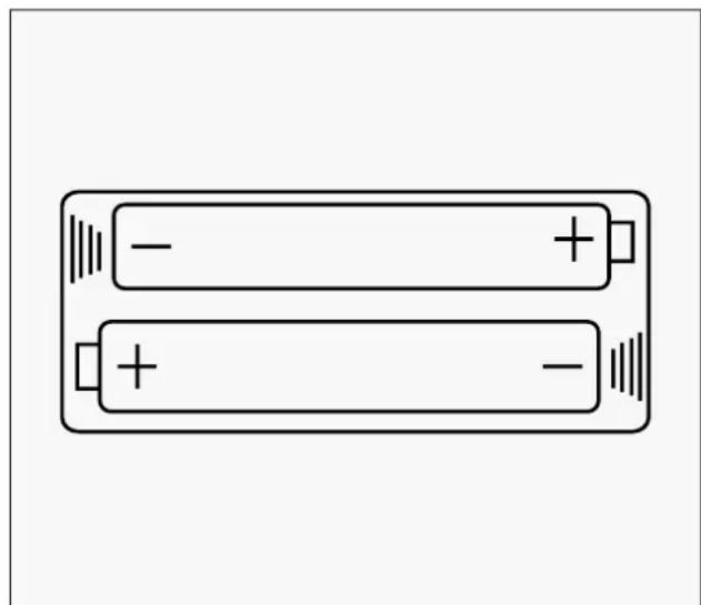
BATTERY USAGE
- Batteries are to be installed or replaced by adult only.
- Do not use rechargeable batteries. Do not mix different battery types. Do not mix old and new batteries. Do not mix alkaline, standard (Carbon-Zinc), or rechargeable (Nickel-Cadmium) batteries.
- Remove batteries when product is not in use.
- Remove exhausted batteries from product and dispose of in accordance with the manufacturer's recommendation.
- Do not attempt to recharge non-rechargeable batteries.
- Batteries are to be inserted with correct polarity.
- The supply terminals are not to be short-circuited.
- Do not dispose of batteries in fire, batteries may explode or leak.
natural_image
Simple line drawing of two batteries with positive and negative terminals, no text or symbols presentIII. EXPLODED DIAGRAM
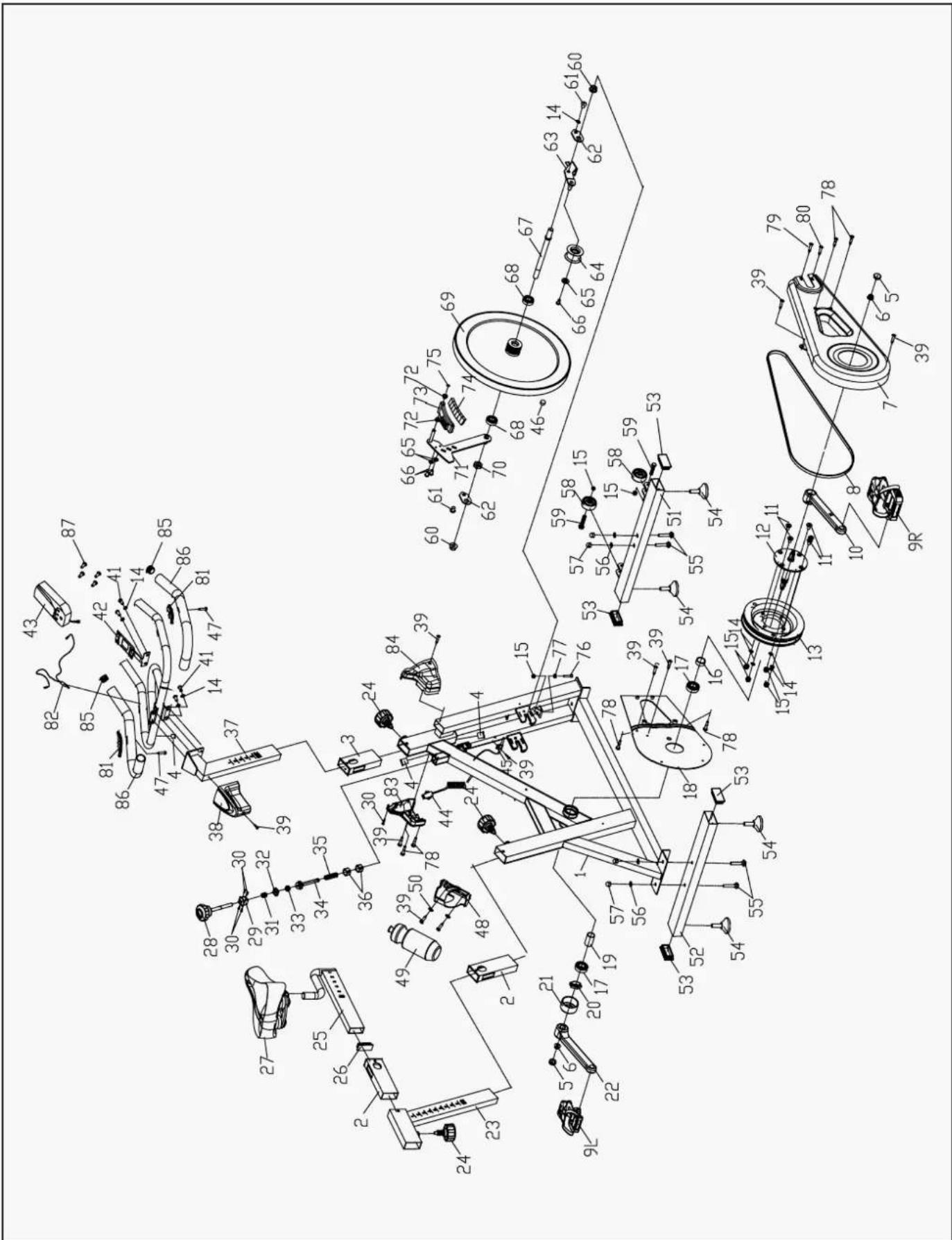
IV. PARTS LIST
NO. Name Quantity Specifications
| 1 | Main Frame 1 Weldment | |
| 2 | Plastic Sleeve 2 Material:pp | |
| 3 | Plastic Sleeve 1 Material:pp | |
| 4 | Plastic Plug 3 Φ14*14 | |
| 5 | Plastic Plug 2 Φ23*7.5 | |
| 6 | Hex Flange Nut 2 M10*1.25 | |
| 7 | Decorative Cover 1 736*70*292 | |
| 8 | Belt 1 5Pk 53In | |
| 9R | Pedal 1 Jd-301(9/16") R | |
| 9L | Pedal 1 Jd-301(9/16") L | |
| 10 | Right Crank 1 170*27 | |
| 11 Bolt | 4 M8*18 | |
| 12 | Core Shaft | 1 Φ20*158 |
| 13 | Pulley | 1 Φ200*21 |
| 14 | Elastic Washer | 8 8 |
| 15 | Lock Nut | 7 M8 |
| 16 | Metal Tube | 1 Φ25*Φ20.05*6 |
| 17 | Bearing | 2 6004Zz |
| 18 | Decorative Cover 1 447*288*23 | |
| 19 | Metal Tube | 1 Φ25*Φ20.05*41 |
| 20 | Hexagon Nut | 1 Φ28*M20*1 |
| 21 | Decorative Cover | 1 447*288*23 |
| 22 | Left Crank | 1 Φ25*Φ20.05*41 |
| 23 | Vertical Seat Post | 1 Φ28*M20*1 |
| 24 | Adjustment Knob | 3 Φ57*62 (M16*1.5), L=20 |
| 25 | Seat Post | 1 Weldment |
| 26 | Plastic Plug | 1 Material:pp/53.5*23.5*1.5 |
| 27 | Seat | 1 Dd-2681 |
NO. Name Quantity Specifications
| 28 | Brake Knob 1 M10*100 | |
| 29 | Plastic Sleeve 1 Pa66 | |
| 30 | Screw 5 St2.9*9.5 | |
| 31 | Spring 1 Φ15.5*Φ1.5x15 | |
| 32 | Square Nut 1 20*20*T8(M10) | |
| 33 | Lock Nut 1 M10 | |
| 34 | Brake Lever 1 Weldment | |
| 35 | Spring 1 Φ2.0*52 | |
| 36 | Square Plastic Block 2 20.6*20.6*16 | |
| 37 | Handlebar Post 1 Weldment | |
| 38 | Decorative Cover | 1 115*89*75 |
| 39 | Screw 2 St4.2x19 | |
| 40 | Handlebar | 1 Weldment |
| 41 | Bolt | 4 M8*15 |
| 42 | Computer Bracket | 1 Weldment |
| 43 | Computer | 1 St-7607 |
| 44 | Sensor | 1 Sr-202 |
| 45 | Sensor Bracket | 1 Ltf8163 |
| 46 | Magnet | 1 Φ15*7 |
| 47 | Screw | 2 St4.2*19 |
| 48 | Kettle Bracket | 1 117*85*90 |
| 49 | Kettle | 1 Xs-003(1#) |
| 50 | Flat Washer | 2 5 |
| 51 | Front Stabilizer | 1 Weldment |
| 52 | Rear Stabilizer | 1 Weldment |
| 53 | Plastic Plug | 4 Pp |
| 54 | Leveling Adjuster | 4 Φ38*43(M8x25) |
| 55 | Carriage Bolt | 4 M8*42 |
| 56 | Flat Washer | 4 8 |
| 57 | Domed Nut | 4 M* |
| 58 | Wheel | 2 Φ50*23 |
NO. Name Quantity Specifications
| 59 | Bolt 2 M8*40 | |
| 60 | Hex Flange Nut 2 M12x1.25 | |
| 61 | Bolt 2 M8*10 | |
| 62 | Metal Plate 2 Δ2.5 | |
| 63 | Pinch Roller Holder 1 Weldment | |
| 64 | Wheel 1 Φ43*Φ34*24 | |
| 65 | Flat Washer 3 Φ14*Φ6*T2.5 | |
| 66 | Bolt 3 M6*12 | |
| 67 | Core Shaft 1 Φ16*Φ12*156 | |
| 68 | Bearing 2 6001Zz | |
| 69 | Flywheel 1 18Kg | |
| 70 | Hexagon Nut | 1 M12x1.25 H=7 |
| 71 | Supporting Frame | 1 Weldment |
| 72 | Plastic Sleeve | 2 Φ18*Φ10*10 |
| 73 | Magnet Holder | 1 Weldment |
| 74 | Magnet | 7 30*15*10 |
| 75 | Circlip | 1 Gb894.1 Φ10 |
| 76 | Bolt 1 M8*45 | |
| 77 | Hexagon Nut | 1 M8 |
| 78 | Screw | 6 St4.2*16 |
| 79 | Screw | 5 St4.2*13 |
| 80 | Screw | 1 St4.2x9.5 |
| 81 | Pulse Sensor | 2 Lt16 |
| 82 | Pulse Sensing Line | 1 L=700 |
| 83 | Decorative Cover | 1 175*72.5*177 |
| 84 | Decorative Cover | 1 175*78*177 |
| 85 | End Cap | 2 Φ23*Φ29*465 |
| 86 | Foam Grip | 2 Φ25*1.5 |
| 87 | Screw | 4 M5*12 |
V. ASSEMBLY INSTRUCTIONS

NOTE! Before assembly ensure there is enough space around the item.
Check and count all parts are present. Note: Some nuts and bolts may be already attached to the machine.
TOOLS

STEP 1
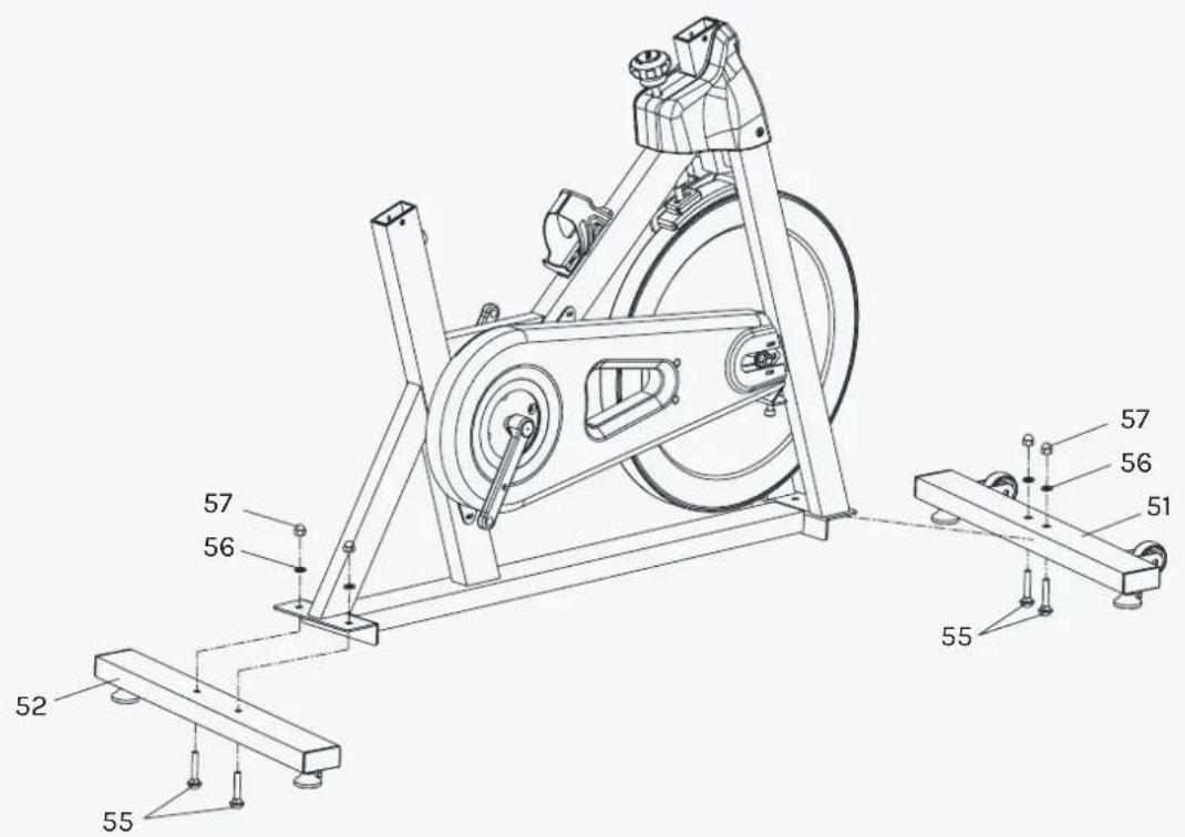
- Lock the Front Stabilizer (pt.51) to the Main Frame (pt.1) with two sets of ∅8 Flat Washer (pt.56), M8 Domed Nut (pt.57) and M8*42 Carriage Bolt (pt.55).
- Lock the Rear Stabilizer (pt.52) to the Main Frame (pt.1) with two sets of ∅8 Flat Washer (pt.56), M8 Domed Nut (pt.57) and M8*42 Carriage Bolt (pt.55).

STEP 2
-
Insert the Vertical Seat Post (pt.23) into the seat post tube of the Main Frame. You will have to slacken the Knob (pt.24) and pull the knob back. Then select the desired height. Release the knob and retighten the knob.
-
Insert the Seat Post (pt.25) into the Vertical Seat Post (pt.23), then fix it with the Knob (pt.24). The Seat (pt.27) can be fixed on the Seat Post (pt.25) with the nuts at the bottom of the seat.
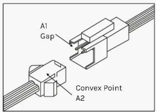
! ATTENTION:
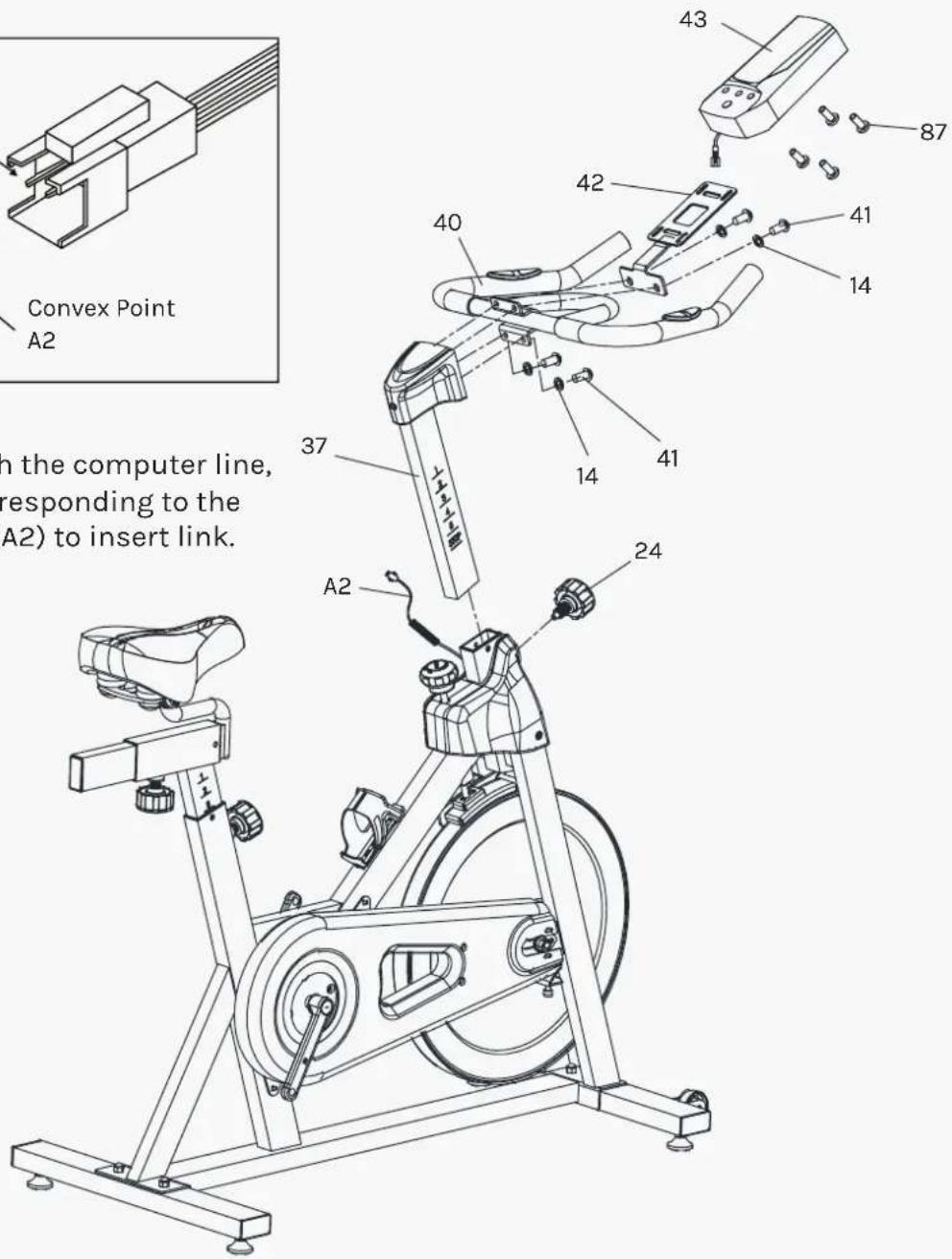
Connected with the computer line, to Gap (A1) corresponding to the convex point (A2) to insert link.
STEP 3
- Insert the Handlebar Post (pt.37) into the handlebar post tube of the main frame. You will have to slacken the Knob (pt.24) and pull the knob back. Then select the desired height. Release the knob and retighten the knob.
- Lock the Handlebar (pt.40) and the Computer Bracket (pt.42) to the Handlebar Post (pt.37) with four sets of the Bolt (pt.41) and the Elastic Washer (pt.14).
- The Computer (pt.43) can be fixed on the Computer Bracket. The A1 & B1 plug into the corresponding jack on the back of the Computer (pt.43).
! ATTENTION: YOU SHOULD FIX THE HANDLEBAR TIGHTLY.

STEP 4
- The Pedals (pt.9L & pt.9R) are marked "L" and "R"- Left and Right. Connect them to their appropriate crank arms. The right crank arm is on the right-hand side of the cycle as you sit on it.
Important Note: that the Right pedal should be threaded on clockwise and the Left pedal anticlockwise.
- The Kettle Bracket (pt.48) can be fixed on the main frame with two Screws (pt.39) and two Flat Washers (pt.50). Put the Kettle (pt.49) into the Kettle Bracket (pt.48).
ADJUSTING THE TENSION

natural_image
Line drawing of an exercise bike with labeled components and motion arrow (no text or symbols beyond basic diagram)1. Adjust the Resistance
To increase resistance (requiring more strength to pedal), turn the Resistance Control Knob (pt.28) to the right.
To decrease resistance (requiring less strength to pedal), turn the Resistance Control Knob (pt.28) to the left.

2. The Emergency Brake Function
The Resistance Control Knob can be used as the Emergency Brake.
When you want the flywheel to stop turning, you must firmly press down the Emergency Brake & Resistance Control Knob (pt.28).
VI. COMPUTER OPERATION
BUTTONS
| MODE To confirm all settings. | |
| SET | To set up the value of TIME, DISTANCE, CALORIES and PULSE. You can hold the button to increase the value fast. (The computer has to be in stop condition). |
| RESET | To clear the set-up value. Press RESET key and hold for 2 seconds to reset all function figures. |
| RECOVERY To test heart rate recovery status. | |
FUNCTIONS
| SCAN Displays all function TIME, DISTANCE, CALORIES, PULSE, RPM/SPEED in sequence. | |
| RPM | Displays the pedaling Rotation Per Minute. The RPM and SPEED will switch to another display in every 6 seconds after exercise starts. |
| SPEED Displays the user's exercise speed. | |
| TIME | You can press "SET" button to set target time between 0:00 to 99:00 for count downIt can be set up by the user or accumulated automatically for count up function. |
| DISTANCE | You can press "SET" button to set target distance between 0:00 to 99:50 for count down function.It can be set up by the user or accumulated automatically for count up function. |
| PULSE | Displays the user's pulse. User may set the target pulse.When pulse value reaches to the target, the computer will alarm with "Bi" sound. |
OPERATION PROCEDURE
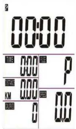
- Installs 2 pieces of 1.5V #4 batteries, then the screen will display as following "Drawing A" and have "Bi" sound at the same time.
After that, it goes to the next step to the main menu as "Drawing B".

- Get access to the set-up mode of TIME/DISTANCE/CALORIES/PULSE.
When you are in each set-up mode, for example in the time set-up mode: time value is blinking, you can press "SET" button to adjust the value and press "MODE" for confirmation. The set-up of DISTANCE, CALORIES & PULSE is the same as TIME.
- With any signal been transmitted into the monitor, the value of TIME, DISTANCE, CALORIES start to count up as Drawing C. When there is any function has been pre-set the target (TIME or DISTANCE or CALORIES), the function will be counting down from the pre-set to zero while the training starts.
Once the target is achieved to zero, the monitor start to beep for 8 seconds, and the function will be counting up from zero directly if the training is going. Press "MODE" button for confirmation and skip to next set-up.
-
In SCAN mode shown as "Drawing C". RPM/SPEED/TM/DIST/CAL/PULSE will skip to display in every 6 seconds. The order is as follows.
-
You can also press "MODE" button to select single function display except RPM & SPEED function. The RPM & SPEED function will switch display.
Drawing C

6. Recovery:
a. When the user presses "RECOVERY" button, the RECOVERY function is active. At this time only PULSE and TIME is working, other functions will not be displayed, and the Sensor Input is not available. TIME starts to count down from "0:60", Pulse signal will be blinking according user's heart rate BPM. When Time counts down to "0", it will show F1\~F6. (F1 is the best, F6 is the worst)
| F1 OUTSTANDING | |
| F2 EXCELLENT | |
| F3 GOOD | |
| F4 FAIR | |
| F5 BELOW AVERAGE | |
| F6 POOR | |
- LCD display as follows: (RECOVERY start condition & end condition).
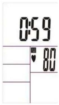

b. If the countdown action to 0:00 is not completed and there is no pulse signal, the countdown action must be done and shown F6.
c. If you press the RECOVERY button prior to count down to 0:00, it will be end and return to the main menu.

NOTE:
-
If paused training for 4 minutes, the computer will enter to Sleep mode. You may press any button to have the computer restart, the original value will retain. (If re-installing batteries, the original value will reset.)
-
If the computer displays abnormally, please re-install batteries and try again.
- Battery Spec: 1.5V UM-4 or AAA (2PCS).
! PLEASE NOTE:
Before beginning any exercise program, consult your physician. This is important especially if you are over the age of 45 or individuals with pre-existing health problems.
The pulse sensors are not medical devices. Various factors, including the user's movement, may affect the accuracy of heart rate readings. The pulse sensors are intended only as an exercise aid in determining heart rate trends in general.
Exercising is great way to control your weight, improving your fitness and reduce the effect of aging and stress. The key to success is to make exercise a regular and enjoyable part of your everyday life.
The condition of your heart and lungs and how efficient they are in delivering oxygen via your blood to your muscles is an important factor to your fitness. Your muscles use this oxygen to provide enough energy for daily activity. This is called aerobic activity. When you are fit, your heart will not have to work so hard. It will pump a lot fewer times per minute, reducing the wear and tear of your heart.
So as you can see, the fitter you are, the healthier and greater you will feel.

natural_image
Four sequential line drawings of a person performing a stretching or martial arts pose, no text or symbols present.WARM UP
Start each workout with 5 to 10 minutes of stretching and some light exercises. A proper warm-up increases your body temperature, heart rate and circulation in preparation for exercise. Ease into your exercise.
After warming up, increase the intensity to your desired exercise program. Be sure to maintain your intensity for maximum performance. Breathe regularly and deeply as you exercise.
COOL DOWN
Finish each workout with a light jog or walk for at least 1 minute. Then complete 5 to 10 minutes of stretching to cool down. This will increase the flexibility of your muscles and will help prevent post-exercise problems.
WORKOUT GUIDELINES

line
| AGE | HEART RATE | | --- | --- | | 20 | 160 | | 40 | 120 | | 75 | 90 |This is how your pulse should behave during general fitness exercise. Remember to warm up and cool down for a few minutes.
VIII. WARRANTY
AUSTRALIAN CONSUMER LAW
Many of our products come with a guarantee or warranty from the manufacturer. In addition, they come with guarantees that cannot be excluded under the Australian Consumer Law. You are entitled to a replacement or refund for a major failure and compensation for any other reasonably foreseeable loss or damage.
You are entitled to have the goods repaired or replaced if the goods fail to be of acceptable quality and the failure does not amount to a major failure. Full details of your consumer rights may be found at www.consumerlaw.gov.au.
Please visit our website to view our full warranty terms and conditions:
http://www.lifespanfitness.com.au/warranty-repairs
WARRANTY AND SUPPORT
Any claim against this warranty must be made through your original place of purchase. Proof of purchase is required before a warranty claim may be processed.
If you have purchased this product from the Official Lifespan Fitness website, please visit https://lifespanfitness.com.au/warranty-form
For support outside of warranty, if you wish to purchase replacement parts or request a repair or service, please visit https://lifespanfitness.com.au/warranty-form and fill in our Repair/Service Request Form or Parts Purchase Form.
Scan this QR code with your device to go to lifespanfitness.com.au/warranty-form

- ! IMPORTANT
- TABLE OF CONTENTS
- IMPORTANT SAFETY INSTRUCTIONS
- WARNING: Read all instructions before using this machine.
- CARE INSTRUCTIONS
- IMPORTANT
- BATTERY USAGE
- EXPLODED DIAGRAM
- PARTS LIST
- ASSEMBLY INSTRUCTIONS
- STEP 1
- ! ATTENTION:
- STEP 3
- ! ATTENTION: YOU SHOULD FIX THE HANDLEBAR TIGHTLY.
- STEP 4
- ADJUSTING THE TENSION
- Adjust the Resistance
- The Emergency Brake Function
- COMPUTER OPERATION
- OPERATION PROCEDURE
- Recovery:
- NOTE:
- ! PLEASE NOTE:
- WARM UP
- COOL DOWN
- WORKOUT GUIDELINES
- WARRANTY
- AUSTRALIAN CONSUMER LAW
- WARRANTY AND SUPPORT
Brand : LifeSpan
Model : SM-410
Category : Home trainer