
OR-VID-EX-1060PMV - Intercom VIBELL - Kostenlose Bedienungsanleitung
Finden Sie kostenlos die Bedienungsanleitung des Geräts OR-VID-EX-1060PMV VIBELL als PDF.


| Produkttyp | Video-Türsprechanlage (Gegensprechanlage) |
| Marke | VIBELL |
| Modell | OR-VID-EX-1060PMV |
| Bildschirm | 7-Zoll-Farb-LCD-Touchscreen |
| Abmessungen (B x H x T) | 185 x 127,5 x 18 mm |
| Gewicht | 0,385 kg |
| Stromversorgung | 15 V DC |
| Leistungsaufnahme | max. 9 W, Standby 1 W |
| Funktionen | Freisprechfunktion, Türöffner, DVR-Aufnahme, Anrufbeantworter, Wecker, Kalender, Erweiterbar auf bis zu 4 Monitore und 2 Außenstationen, 7 Klingeltöne, SD-Kartenslot |
| Installation | 4-Draht-Verkabelung; empfohlene Kabelquerschnitte: bis 30 m 3x2x0,5 mm², 30-100 m 3x2x0,8 mm² |
| Betriebstemperatur | 0 °C bis +50 °C |
| Luftfeuchtigkeit | 0% bis 95% |
| Reinigung | Nach Montage Schutzfolie entfernen; Gehäuse mit trockenem Tuch reinigen |
| Sicherheit | Vor Wartung Netzstecker ziehen; Gerät nicht in Flüssigkeiten tauchen; keine Eigenreparatur |
| Zubehör | Kompatibel mit elektrischen Türöffnern (12 V DC, max. 450 mA) und Zusatzkameras |
| Reparatur | Nur durch qualifiziertes Personal; Garantieverlust bei Eigenreparatur |
Häufig gestellte Fragen - OR-VID-EX-1060PMV VIBELL
Benutzerfragen zu OR-VID-EX-1060PMV VIBELL
0 Frage zu diesem Gerät. Beantworten Sie die, die Sie kennen, oder stellen Sie Ihre eigene.
Eine neue Frage zu diesem Gerät stellen
Laden Sie die Anleitung für Ihr Intercom kostenlos im PDF-Format! Finden Sie Ihr Handbuch OR-VID-EX-1060PMV - VIBELL und nehmen Sie Ihr elektronisches Gerät wieder in die Hand. Auf dieser Seite sind alle Dokumente veröffentlicht, die für die Verwendung Ihres Geräts notwendig sind. OR-VID-EX-1060PMV von der Marke VIBELL.
BEDIENUNGSANLEITUNG OR-VID-EX-1060PMV VIBELL
VIDEO MONITOR
OPERATING AND INSTALLATION INSTRUCTIONS
Model: OR-VID-EX-1060PMV
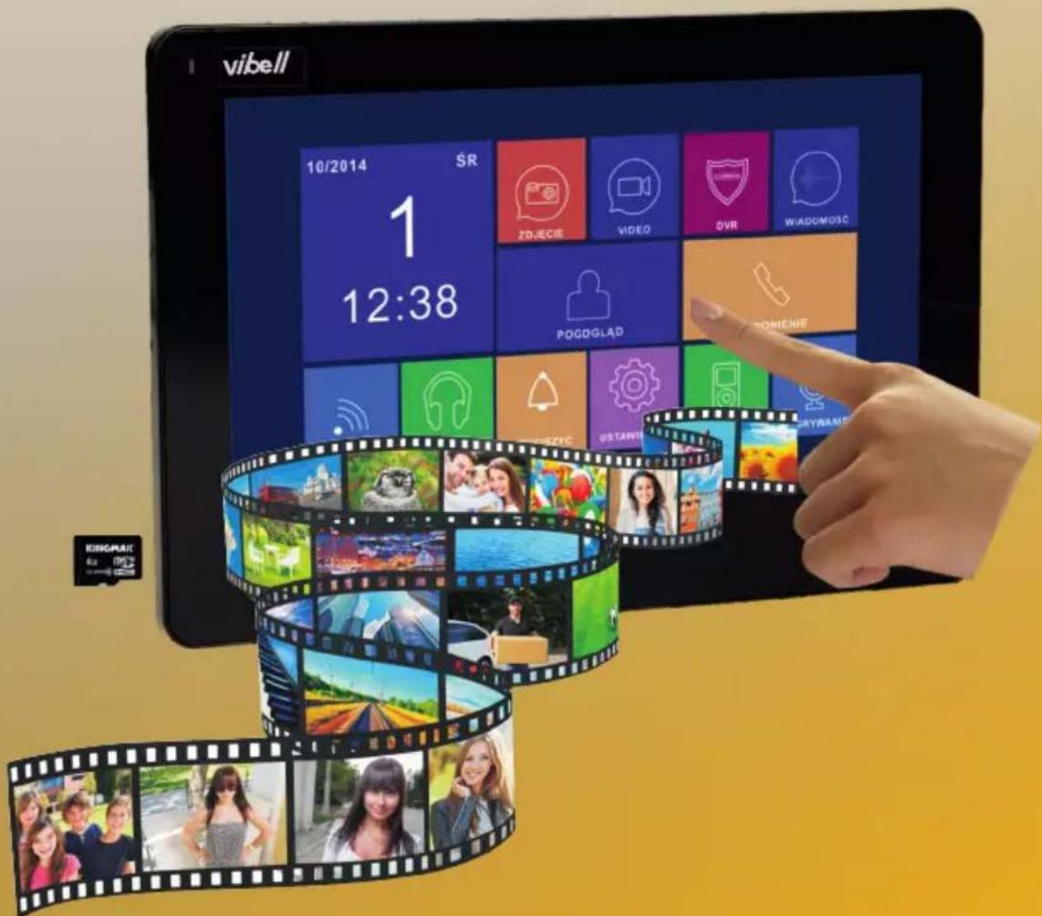
TABLE OF CONTENTS
REMARKS 3
MAIN FEATURES AND FUNCTIONS 3
CONSTRUCTION OF MONITOR 4
INSTALLATION AND WIRING DIAGRAM 5
MOUNTING 8
CABLE SPECIFICATIONS 8
OPERATION 9
- Main system menu 9
- Operation menu 10
- Receiving incoming calls 10
- Volume level adjustment 11
- Brightness/color/contrast adjustment 11
- Monitoring 11
- Intercom functions 11
- Transmitting function 11
- Sound monitoring 12
- Image capturing 12
-Auto DVR function 12
- VIDEO manual recording 12
-Answering machine 13
- Changing the answering machine message 13
- Alarm clock and electronic calendar 14
- View photos, videos, DVRs and media files 14
- Deleting single files and folders 15
- Image capturing, video recording and DVR parameters 16
- System settings 16
PROBLEM SOLVING 22
TECHNICAL DATA 23
Please read this manual carefully before connecting and using the device. In case something written herein is unclear, please contact the seller. Installation and commissioning of the equipment by the customer are possible if the installer has basic knowledge of electrical systems and the use of proper tools. Nevertheless, the device installation by qualified personnel is recommended.
The manufacturer is not responsible for any damage that can result from improper device installation or operation. Any repair or modification carried out by yourselves results in loss of guarantee.
In view of the fact that the technical data are subject to continuous modifications, the manufacturer reserves a right to make changes to the product characteristics and to introduce different constructional solutions without deterioration of the product parameters or functional quality. Any translation/interpretation rights and copyright in relation to this Manual are reserved.
- Disconnect the power supply before performing any activities.
2.Do not immerse the product in water or other liquids. - Do not operate the device with damaged housing.
- Do not open or repair the device yourself.
- Do not use the device contrary to its dedication.
- Do not install the monitor near equipment that emits a strong magnetic field such as television, loudspeakers.
- Do not install the monitor in a location exposed to high humidity, vibration, shock or strong sunlight.
- Turn off the power if there are any "not normal" sounds coming from the device.
- After installation and mounting, remove the protective film from the monitor screen.
Each household is a user of electrical and electronic equipment, and hence a potential producer of hazardous waste for humans and the environment, due to the presence of hazardous substances, mixtures and components in the equipment. On the other hand, used equipment is valuable material from which we can recover raw materials such as copper, tin, glass, iron and others. The wee sign placed on the equipment, packaging or documents attached to it indicates the need for selective collection of waste electrical and electronic equipment. Products so marked, under penalty of fine, cannot be thrown into ordinary garbage along with other waste.

The marking means at the same time that the equipment was placed on the market after August 13, 2005. It is the responsibility of the user to hand the used equipment to a designated collection point for proper processing. Used equipment can also be handed over to the seller, if one buys a new product in an amount not greater than the new purchased equipment of the same type. Information on the available collection system of waste electrical equipment can be found in the information desk of the store and in the municipal office or district office. Proper handling of used equipment prevents negative consequences for the environment and human health!
MAIN FEATURES AND FUNCTIONS
• Part of the Vibell video intercom system
- 7" high resolution colour LCD screen
- Ultra-slim, hands-free monitor
- Touch screen panel
- OSD menu in Polish and English
- Memory module
- Slot for external SD card
• DVR monitoring function (recording of video sequences)
- Answering machine function
- Alarm clock and timer
- Intercom function with additional monitor
- 7 ringtones to choose from
- Adjustment of brightness, color and volume of ringing and calling
- Expandable with additional video door entry cameras and CCTV cameras
- Allows you to hold a conversation with a person at the entrance and simultaneous observation on a monitor screen
- Remote control of an electric door strike (not supplied) and an automatic gate control unit
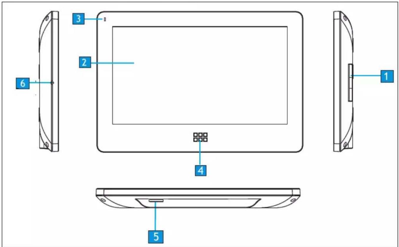
| Nr | Lp. | Functional description |
| 1 | Loudspeaker | |
| 2 | LCD | |
| 3 | Indicator | Power indicator |
| 4 | Button | Entry to main menu |
| 5 | MicroSD card slot | |
| 6 | Microphone |
1. Port 2 external panel connection
The system can support up to 1 main monitor, 3 additional monitors, 2 external panels with camera and 8 CCTV cameras.
![graph TD A["EXTERNAL PANEL 1"] --> B["MAIN MONITOR"] C["EXTERNAL PANEL 2"] --> B B --> D["CCTV1"] B --> E["CCTV2"] D --> F["ADDITIONAL MONITOR"] E --> F F --> G["CCTV1"] F --> H["CCTV2"] G --> I["ADDITIONAL MONITOR"] H --> I I --> J["CCTV1"] I --> K["CCTV2"] J --> L["ADDITIONAL MONITOR"] K --> L](/content/2026/05/893498/images/8df7c8d572bcef99d66a611a822bb885b5183c9c2a488d76b823e9df5f202bc7.jpg)
2. Port 2 connection of CCTV cameras
The system can support up to 1 main monitor, 1 external panel with camera, 9 CCTV cameras and 3 additional monitors.
![graph LR A["EXTERNAL PANEL 1"] --> B["CCTV3"] B --> C["MAIN MONITOR"] C --> D["CCTV1"] C --> E["CCTV2"] D --> F["ADDITIONAL MONITOR"] E --> F F --> G["CCTV1"] F --> H["CCTV2"] G --> I["ADDITIONAL MONITOR"] H --> I I --> J["CCTV1"] I --> K["CCTV2"] J --> L["ADDITIONAL MONITOR"] K --> L](/content/2026/05/893498/images/b2e2b42d3934e2b29fb083717f2de342dd66ad812e9c105414ea0b8d0bfd5b0f.jpg)
While designing the wiring system, take into account the suitable cross-section of cables:
up to 30 m - recommended cable XzTKMXpw 3 x 2 x 0.5 mm 2
from 30 m to 100 m - recommended cable XzTKMXpw 3 x 2 x 0.8 mm 2
The connection to the electromagnetic lock should be made with 2 x 1 mm 2 .
The set is compatible with any electric door strike with voltage of 12V DC (not included).
Electric strike with voltage of 12VDC and current consumption up to 450mA (not included) does not require additional power supply. When connecting, keep the correct polarity as shown in the diagram!
The total length of the installation must not exceed 100 meters.
The use of twisted-pair cables is absolutely not recommended.
Wiring diagram 1
![graph TD A["POWER SUPPLY 12VDC (not included)"] --> B["CAMERA 2"] B --> C["CCVT1"] B --> D["CCVT2"] C --> E["P4"] D --> F["P3"] E --> G["CCTV1"] E --> H["CCTV2"] F --> I["P1"] G --> J["KAMERA 1"] H --> K["P2"] I --> L["MONITOR 1"] J --> M["MONITOR 2"] K --> N["MONITOR 3"] L --> O["MONITOR 4"] M -->…](/content/2026/05/893498/images/23c1554578586ac992c2054a3ab5257e99bd8a5d96e13d0a6595a161e4d9b165.jpg)
Wiring diagram 2
![graph TD subgraph_MONITOR_1["MONITOR 1"] P6["P6"] --> CCVT3["CCVT3"] P3["P3"] --> CCVT1["CCVT1"] P2["P2"] --> CCVT2["CCVT2"] P1["P1"] --> CTV1["CCTV1"] P1 --> CTV2["CCTV2"] P1 --> CTV3["CCTV3"] P2 --> CTV1 P2 --> CTV2 P2 --> CTV3 P1 --> CTV1 P1 --> CTV2 P1 --> CTV3 P1 --> CTV4["CCTV4"] P1 --> CTV5["…](/content/2026/05/893498/images/1b8358e675eaa679e217bf7135232ea9b7e9d42de10106bf73999695893f9cef.jpg)
MOUNTING
- Specify the mounting position of the monitor:
- Suggested height 1.5\~1.6 metres;
- Detach the mounting frame from the back of the monitor.
- Mount the frame on the wall.
- Connect the wiring as shown in the wiring diagram.
- Attach the monitor to the mounting bracket.
- After installing the external panel, connect the power supply.

![graph LR A["Table with monitor icon"] --> B["Device with two buttons"] B --> C["Block wall with window and vertical lines"]](/content/2026/05/893498/images/b011190127742843225fe666d813daa29494cb5de730fc2b31c20bd4ecb5b794.jpg)
Before drilling holes it is recommended to test the operation of the device. For this purpose connect the device according to the wiring diagram. After a thorough check, proceed to making mounting holes after switching off the power supply.
CABLE SPECIFICATIONS
Video intercom cables should not be laid in one cable with cables of other installations e.g. doorbell, alarm etc. Any power and telecommunication cables emitting strong magnetic fields (e.g. loudspeakers, TV set) in direct contact with the wires connecting the external panel with the monitor may adversely affect the set's operation.
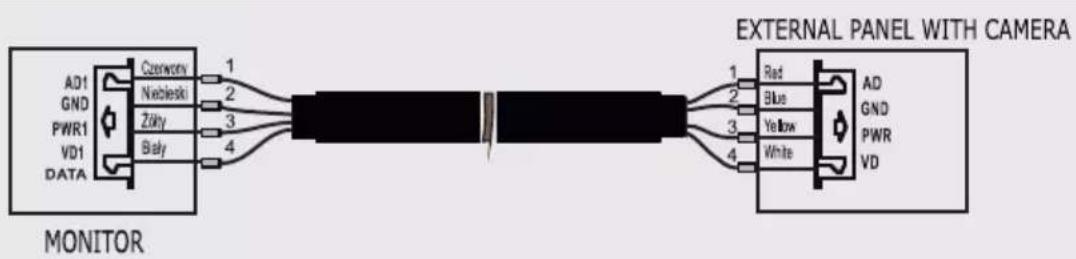
Notes: Refer to the manual of the outdoor panel OR-VID-EX-1057KV, OR-VID-EX-1061KV, OR-VID-EX-1062KV, OR-VID-EX-1063KV for a detailed wiring diagram of the electric door strike.

MAIN SYSTEM MENU
In standby mode, touch the button on the monitor panel ☐ to enter the main menu. To close the menu, swipe to the left.
 | Browse/delete saved images | If there are new/unviewed photos, NO will appear in the right corner. |
 | Review/delete saved movies | If there are new/unwatched videos, NO will appear in the right corner. |
 | Browse/delete DVR files | |
 | Browse/delete files stored on the Micro SD card | |
 | Browse/delete recorded audio filesChange the message signal | If there are new/unwatched audio files, NO will appear in the right corner. |
 | Record audio files | |
 | Calendar | Displays date, day and time |
 | External panel view | Enter monitoring mode of external panel |
 | Call transfer | Enter call transfer mode |
 | Announcement | Transmission to other monitors |
 | Listening | Enter listening mode |
 | System settings | Enter system settings |
OPERATION MENU
The system supports 5 different activities:
- Clicking: clicking on any empty point on the screen will display the operation menu. To hide the menu, click again.
- Move left: Move left to return to the previous menu
- Move right: Hide menu in multimedia user panel / view next image.
- Move up: in the system settings, moves to the last page.
- Move down: in the system settings it moves to the last page.
If the monitor is in monitoring or talk mode the following menu will appear on the right hand side of the screen:
| Descr icons |  |  |  |  |  |  |  |  |
| Recording | Call ending | Call/ Transfer connection | Switching monitor | Monitor parameters adjustment | Image capturing | Save | Unlock |
Receiving incoming calls
Pressing the call button on the external panel will cause all connected monitors to emit a ringing tone and the LCD screen will display the message "CALL COMING".
Touch icon 📊 to start a call (call duration is 60 seconds) If you want to remotely unlock the door, tap the icon 📌. The message DOOR OPENING appears on the screen 1. If you want to open the gate remotely, touch the icon 📌.
-
If a new call is received during the call, the message GUEST AT THE DOOR 2 will be displayed. To go to the second call, touch the icon 📁.
-
While talking to a guest, you can transfer calls to other monitors in the system.
If you want to transfer the call to another person, click the 📋.
(The message TRANSFER TO OTHER ROOMS will appear on the screen).
Volume level adjustment
In call/intercom mode, click the icon 📁 to enter the volume control menu, then click + or — to adjust the volume.
Brightness/color/contrast adjustment
When the screen is turned on, tap the icon 📄 to adjust the volume first,
and then click on the icon again to enter the adjustment menu BRIGHT/COLOR/CONT, click + or - to adjust brightness, colour and contrast.
Monitoring - control of external panels or CCTV cameras
In standby mode, tap on the monitor □□□ to enter the main system menu, and then tap the icon. You can display images from the connected outdoor panel and CCTV cameras.

While monitoring the outdoor panel, you can mute the bell microphone. To do this, tap the icon If the microphone is in normal mode, click 📄 to open the door.

If the system is extended with additional monitors (maximum 4), the following operations can be performed.
Intercom functions
In monitor standby mode, touch ☐☐☐ to enter the main system menu and then tap the icon to activate the function. If you have more than 2 monitors connected to each other you can select the NR of the target monitor on the screen.

Transmitting function
This function allows information to be transmitted to all monitors in the house.
In standby mode touch 📄 to enter the main system menu, then tap the icon
The screen will show SEND REQUEST and the other monitors will show SEND.
You can now start transmitting.
Sound monitoring
To activate the function enter the main system menu by touching □□□, then tap the icon ▼.
If you have more than 2 internal monitors connected, you can click the NR of the target monitor on the screen.
Important:
a: In audio monitoring mode, the user can listen to the sounds in the monitored room, but the persons in the room being monitored will not hear the monitoring person's voice.
b: The audio monitoring function is only available when the MAY BE MONITORED on the desired monitor has been enabled. Check the system menu to see how to activate the MAY BE MONITORED function.
Image capturing
-
Automatic image capture: "Automatic capture quality" should be set to 1, 2 or 3 in SYSTEM SETTINGS. The system will automatically take and save pictures when a visitor rings the doorbell.
-
Manual image capture: In talk and monitoring mode, tap the icon, to capture an image manually. The screen displays the IMAGE CAPTURED.
Auto DVR function
To activate the function, enter the main system menu by tapping ☐☐☐, then touch the icon

It is possible to record video images from the camera of an external panel or CCTV camera at a preset time.
Important:
(a) DVR function does not record sound.
(b) To fully utilise the DVR function, an 8G microSD card must be connected.
(c) To obtain a high quality video image, please select the resolution: 640* 480.
(d) If you set a start date and an end date at the same time, the DVR function will start immediately within 24 hours and remain permanently on.
VIDEO manual recording
In call or monitoring mode, touch the icon 📄 to record the image manually.
Tap the icon again 📄 to complete the registration.
Answering machine
This function allows your guests to leave a voice message when no one is home. Activate the AUTOMATIC LEAVING OF VOICE MESSAGE function in the SYSTEM SETTINGS menu before leaving the house. After the guest presses the call button on the external panel and no one answers before the bell signal ends, the guest will hear the message "Good morning, no one is in home at the moment, please leave a message after the signal" and the guest will have 20 seconds to record their message.
Changing the answering machine message
If you want to change the answering machine message in the system menu, press the 📄 and register your voice message.
Then exit the current function and press the icon 📋.
The screen will display the recorded AUDIO files as shown in Figure 1.

fig. 1
Touch the audio file you want to set as the start signal and then touch the icon (Signal setting) to enter the "ALARM TONE SETTING" menu. ALARM TONE" as in Fig. 2

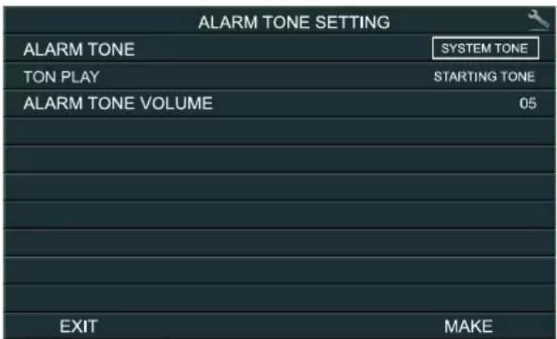
fig. 2
To change the ALARM TYPE option, touch the SYSTEM TONE or USER TONE icon.
PLAY TONE: you can set a separate welcome message and a separate goodbye message by clicking: STARTING TONE or ENDING TONE
To change the message volume set the ALARM TONE VOLUME from 01 to 10 by clicking the desired value.
To confirm the settings touch MAKE or to cancel touch EXIT.
Alarm clock and electronic calendar
.1. Settings of the TIMER should be made in the main menu in the SYSTEM SETTINGS.
2. When the alarm clock is activated, you can turn it off by clicking the bell icon in the upper left corner of the screen.
3. When the image as shown in figure 3 appears on the screen, click on the clock in the left corner of the screen and the time displayed in the right corner, then set the appropriate parameters.

fig. 3
View photos, videos, DVRs and media files
In standby mode press to go to the main system menu. The number of unviewed files is displayed as a red icon in the right-hand corner of the screen. The file names consist of the date and time the file was created, for example 01-02-2012 11:30:20 means the file was created at 11:30:20, 1 January 2012. This makes it easy for you to check the save time and file names.
- Photo preview:
Touch icon 📄 to access the list of photo files, then click on the desired file.
Click ⇔ or → to view your photos.
The images will change automatically every 5 seconds.
If you want to leave the image gallery, click the icon to return to the previous menu.

fig. 4
- Video preview:
Touch icon 📄 to access the list of photo files, then click on the desired file.
To play the video click on the appropriate icon,
to exit click

fig. 5

- Play from DVR:
Touch icon 📋 to access DVR files. Follow the same procedure as for playing video files (video preview).
- Browse multimedia files:
Touch icon 📋 to access to view media files.
By following the steps as above, you can view image files and play music (photo preview).
Important:
If a microSD card has not been installed in the unit, you can view images stored in the monitor's internal memory.
Deleting single files and folders
If you want to delete a file or folder, select the file or
folder to delete from the list and then click

and then DELETE to confirm or EXIT to cancel.
IMPORTANT
You can delete image, audio or DVR files in the same way.

fig. 6
Image capturing, video recording and DVR parameters
Image capturing function
| Memory place | Resolution | Image quality |
| Internal flash memory | 320x240 | More than 64 pieces |
| External microSD card | 640x480 | Depends on microSD card capacity |
Video recording function
| MicroSD card capacity | Resolution | FPS |
| 1G | 320x240 | 2 |
| 2G | 320x240 | 5 |
| 4G | 320x240 | 10 |
| >8G | 640x480 | 10 |
DVR function
| MicroSD card capacity | Resolution | FPS | Video recording time |
| <2G | No DVR function | ||
| 2G | 320x240 | 1 | Over 24 hours |
| 4G | 320x240 | 1, 2, 5 | After setting the frame rate to 1 - more than48 hours |
| 8G | 320x240 | 1, 2, 5, 10 | After setting the frame rate to 1 - more than96 hours |
| >16G | 320x240 or 640x480 | 1, 2, 5, 10 | After setting the frame rate to 1 and resolution 320x240 - more than192 hours |
Important: (a) Video recording time will vary depending on the material being recorded (In the worst case, a 2G card can record 28 hours of video at 320*240 resolution and 1 frame per second; in the best case, over 72 hours of video can be recorded).
(b) JIf system users save the system audio in their own language, we suggest that the save time should not exceed 20 seconds; otherwise the files may be deleted when formatting the microSD card.
System settings
After entering the main system menu, click in Figures 7, 8, 9.

to enter the system settings menu as shown

fig. 7
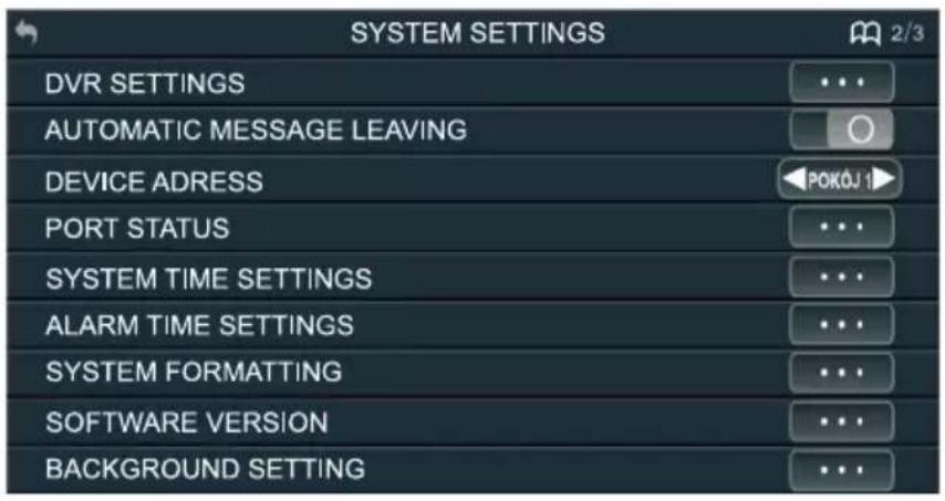
fig. 8

fig. 9
| No. | Setting items | Options | Notes | ||
| 1-1 | RINGING DURATION | 10S/15S/20S/25S/30S/35S/40S/45S/50S/55S/60S | Ringing time | ||
| 1-2 | RINGING VOLUME LEVEL | 10~100% | |||
| 1-3 | RINGING TYPE | DOOR 1 RING TYPE DOOR 2 RING TYPE INTERCOM RING TYPE | 00-07 | ||
| BACK TO TONE | The ringing tone will be repeated if the option is | ||||
| 1-4 | DO NOT DISTURB | 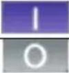 | The internal monitor will be muted when someone presses the ringer/answers an internal call/starts a transmission | ||
| 1-5 | MONITORING | 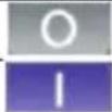 | |||
| 1-6 | PLAY KEY SOUND |  | |||
| 1-7 | ICONS NAME | 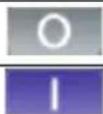 | No icon name is displayed on the screen | ||
| Icon's names are displayed on the screen | |||||
| 1-8 | AMOUNT OF AUTOMATIC CAPTURE | 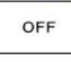 | Do not capture images automatically | ||
| TKWT | Automatic capture of 1 image | ||||
| Automatic capture of images | |||||
 | Automatic capture of images | ||||
| 1-9 | COPYING FILES TO SD CARD | ||||
 | ON | ||||
| 2-1 | RECORDER SETTINGS | RE | D7W2 | ON | |
| MO | S | NSOR | |||
| S | H5ZW | TY | DVR starts recording | ||
| E | DVR ends recording | ||||
| NUMI | CAGES | ||||
| RESOLUTION | |||||
| SCREENSAVER TIME | |||||
| RECORDING SOURCE | |||||

| No. | Setting items | Options | Notes | |
| 2-1-1 | RECORDER ON |  | DVR will start recording at START TIME | |
 | ||||
| 2-1-2 | MOTION SENSOR SENSITIVITY |  | Indicates the sensitivity for starting the motion detector | |
 | ||||
 | ||||
 | ||||
| 2-1-3 | START TIME | HO |  | |
| 2-1-4 | END TIME | HO |  | |
| 2-1-5 | NUMBER OF CAGES | 1/2 | 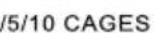 | Depends on MicroSD card capacity |
| 2-1-6 | RESOLUTION |  | Depends on MicroSD card capacity | |
 | ||||
| 2-1-7 | RECORDING SOURCE |  | ||
| DO |  | |||
| CAM |  | |||
| CAM |  | |||
| 2-1-8 | SCREENSAVER TIME | NEVI |  | After the set time, the screen will switch off |
| 05/10 |  | |||
| 40/4 |  | |||
| 2-2 | AUTOMATIC MESSAGE LEAVING |  | ||
 | ||||
| 2-3 | DEVICE ADDRESS | RC |  | If the same addresses are set, this option will be displayed in red |
| 2-4 | STATUS PORT | POI |  | |
| DOO |  | |||
(  | ||||
(  ) ) | ||||
| 2-5 | SYSTEM TIME SETTINGS | DATE:DAY-MONTH-YEAR | ||
| TIME:HOUR:MINUTE:SECOND | ||||
| 2-6 | ALARM TIME SETTINGS | ALARM TIME1 | 1. Each alarm clock can be set independently2. From the set time, the alarm will sound every 50 seconds until the alarm clock is switched off in the menu00-07 | |
| ALARM TIME 2 | ||||
| ALARM TIME 3 | ||||
| ALARM TIME 3 | ||||
| ALARM TIME 4 | ||||
| ALARM TIME 5 | ||||
| ALARM TIME 6 | ||||
| RING TYPE | ||||
| 2-6-1 | ALARM TIME | STATUS | ||
| CYCLE MODE | There are 4 cycles available:SINGLE/WEEK/MONTH/YEAR | |||
| CHOICE OF WEEK | Works only with week type | |||
| TIME | ||||
| DATE | ||||
| 2-6-1-1 | STATUS |  | ||
 | The alarm will sound at the set time | |||
| No. | Setting items | Options | Notes |
| 2-6-1-2 | CYCLE MODE | SINGLE | |
| WEEK | |||
| MONTH | |||
| YEAR | |||
| 2-6-1-3 | CHOICE OF WEEK | SUNDAY | You can set the status for each day by using on/off to create an alarm group |
| MONDAY | |||
| TUESDAY | |||
| WEDNESDAY | |||
| THURSDAY | |||
| FRIDAY | |||
| SATURDAY | |||
| 2-6-1-4 | TIME | HOUR: MINUTE | |
| 2-6-1-5 | DATE | YEAR-MONTHDAY | In single mode, YEAR, MONTH, DAY options are active; in Week mode, all options are inactive; in Month mode, only the Day option is active; in Year mode, only MONTH and DAY option are active |
| 2-7 | SYSTEM FORMATTING | ERASING FLASH MEMORY | |
| DELETING | |||
| 2-8 | SOFTWARE VERSION | ||
| 2-9 | BACKGROUND SETTING | IMAGE1: COLOR1/2/3/4/5/6/7 | |
| 3-1 | RESTORE DEFAULT | ||
| RESTORE | |||
| 3-2 | LANGUAGE | POLISH, ENGLISH, RUSSIAN |
OR-VID-EX-1060PMV
Configuration of gate control settings
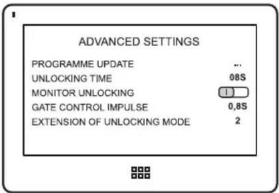
Turn the power off, turn the power back on after 30 seconds, and quickly touch and hold your finger in the centre of the display (matrix). When the message appears: "Please set the system time" remove your finger from the display, touch and hold the □□□, until the advanced settings menu appears on the screen.
UNLOCKING TIME - electric strike opening time (factory setting 05 S change to 08S)
MONITOR UNLOCKING - function used in multi-location systems
GATE CONTROL IMPULSE - factory set as closed (concealed), after connecting the gate control unit it is possible to change the opening time to 0.2 seconds or more.
Extension of the unlocking mode:
for video cameras VIBELL set 2
To exit Advanced Settings press the Main Menu button, your settings will be saved.
PROBLEM SOLVING
- No sound or vision
a) no supply voltage,
b) broken or incorrectly connected monitor.
- Unclear picture
a) check and adjust settings.
- Numerous interferences in the picture, no synchronicity (picture blinks)
a) the connection cable has a cross-section not suited to its length,
b) connection too long - use shielded cable,
c) bad quality of cable,
d) strong source of electromagnetic interference - use shielded cable.
- Audio on the monitor is coupling
a) check your installation against the technical requirements,
b) check that the installation is not exposed to water and moisture etc.
- Electric strike does not open every time
a) check the independent operation of the electric door strike.
- Scratched monitor
a) check that the protective film is removed from the screen.
| Power source | 15V DC |
| Power consumption | 9W max., 1W (standby) |
| Working temperature | 0°C to +50°C |
| Humidity | 0% to 95% |
| Display panel | 7" |
| Intercom function | Hands-free |
| Wiring | 4-wires |
| Dimensions | 185x127.5x18mm |
| Weight | 0.385kg |
PRODUCER
ORNO-LOGISTIC Sp. z o.o.


- VIDEO MONITOR
- TABLE OF CONTENTS
- REMARKS 3
- MAIN FEATURES AND FUNCTIONS 3
- CONSTRUCTION OF MONITOR 4
- INSTALLATION AND WIRING DIAGRAM 5
- MOUNTING 8
- CABLE SPECIFICATIONS 8
- OPERATION 9
- PROBLEM SOLVING 22
- TECHNICAL DATA 23
- MAIN FEATURES AND FUNCTIONS
- PORT 2 EXTERNAL PANEL CONNECTION
- PORT 2 CONNECTION OF CCTV CAMERAS
- WIRING DIAGRAM 1
- MOUNTING
- CABLE SPECIFICATIONS
- MAIN SYSTEM MENU
- OPERATION MENU
- RECEIVING INCOMING CALLS
- VOLUME LEVEL ADJUSTMENT
- BRIGHTNESS/COLOR/CONTRAST ADJUSTMENT
- MONITORING - CONTROL OF EXTERNAL PANELS OR CCTV CAMERAS
- INTERCOM FUNCTIONS
- TRANSMITTING FUNCTION
- SOUND MONITORING
- IMPORTANT
- IMAGE CAPTURING
- AUTO DVR FUNCTION
- VIDEO MANUAL RECORDING
- ANSWERING MACHINE
- CHANGING THE ANSWERING MACHINE MESSAGE
- ALARM CLOCK AND ELECTRONIC CALENDAR
- VIEW PHOTOS, VIDEOS, DVRS AND MEDIA FILES
- DELETING SINGLE FILES AND FOLDERS
- IMAGE CAPTURING, VIDEO RECORDING AND DVR PARAMETERS
- SYSTEM SETTINGS
- OR-VID-EX-1060PMV
- CONFIGURATION OF GATE CONTROL SETTINGS
- PROBLEM SOLVING
Marke : VIBELL
Modell : OR-VID-EX-1060PMV
Kategorie : Intercom