
OR-VID-EX-1061KV - Glocke VIBELL - Kostenlose Bedienungsanleitung
Finden Sie kostenlos die Bedienungsanleitung des Geräts OR-VID-EX-1061KV VIBELL als PDF.


| Produkttyp | Video-Türstation (Außenstation) |
| Modell | OR-VID-EX-1061KV |
| Marke | Vibell |
| Abmessungen | 55 x 152 x 22 mm |
| Gewicht | 0,226 kg |
| Stromversorgung | 12–15 V DC über Monitor |
| Stromverbrauch | 3 W |
| Kommunikation | Freisprechanlage |
| Anschlusstyp | 4 Adern + 2 |
| Videoauflösung | CVBS/720P/1080P |
| Nachtsicht | IR-Beleuchtung, weiße LEDs |
| Kamerablickwinkel | 110° horizontal, 57° vertikal |
| Mindestbeleuchtung | 0,1 Lux |
| Tastatur | Touchscreen-Ziffernfeld |
| Lesereichweite | ≤ 20 mm |
| Maximale Benutzerkarten | 150 Stück |
| Türöffnerausgang | 12 V DC, 1,5 A |
| Schutzart | IP65 |
| Betriebstemperatur | −25 °C bis +60 °C |
| Lagertemperatur | −30 °C bis +60 °C |
| Funktionen | Wiegand-Schnittstelle, Karten-/Transponderleser, Passwort, Video-Intercom |
| Reinigung | Nur weiches, feuchtes Tuch; keine Lösungsmittel |
| Sicherheit | Vor Arbeiten Strom abschalten, nicht selbst öffnen oder reparieren |
| Lieferumfang | Außenstation, Montagerahmen, Schrauben |
Häufig gestellte Fragen - OR-VID-EX-1061KV VIBELL
Benutzerfragen zu OR-VID-EX-1061KV VIBELL
0 Frage zu diesem Gerät. Beantworten Sie die, die Sie kennen, oder stellen Sie Ihre eigene.
Eine neue Frage zu diesem Gerät stellen
Laden Sie die Anleitung für Ihr Glocke kostenlos im PDF-Format! Finden Sie Ihr Handbuch OR-VID-EX-1061KV - VIBELL und nehmen Sie Ihr elektronisches Gerät wieder in die Hand. Auf dieser Seite sind alle Dokumente veröffentlicht, die für die Verwendung Ihres Geräts notwendig sind. OR-VID-EX-1061KV von der Marke VIBELL.
BEDIENUNGSANLEITUNG OR-VID-EX-1061KV VIBELL
VIDEO KAMERA
OPERATING AND INSTALLATION INSTRUCTIONS
Model: OR-VID-EX-1061KV
SAFETY NOTES:
Please read this manual carefully before connecting and using the device. In case something written herein is unclear, please contact the seller. Installation and commissioning of the equipment by the customer are possible if the installer has basic knowledge of electrical systems and the use of proper tools. Nevertheless, the device installation by qualified personnel is recommended.
The manufacturer is not responsible for any damage that can result from improper device installation or operation. Any repair or modification carried out by yourselves results in loss of guarantee.
In view of the fact that the technical data are subject to continuous modifications, the manufacturer reserves a right to make changes to the product characteristics and to introduce different constructional solutions without deterioration of the product parameters or functional quality. Any translation/interpretation rights and copyright in relation to this Manual are reserved.
- Disconnect the power supply before performing any activities.
- Do not immerse the product in water or other liquids.
- Do not operate the device with damaged housing.
- Do not open or repair the device yourself.
- Do not use the device contrary to its dedication.
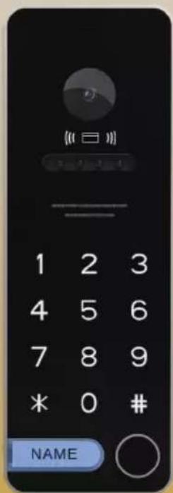
EXTERNAL PANEL CONSTRUCTION

- Microphone
- Camera lens
- Proximity cards and tags reader
- Camera lighting
- Loudspeaker
- Numeric keypad 0-9
- Confirmation button
- Call button
- Password change button
- Name plate
![graph TD A["Camera mode change button"] --> B["1. Brown: Gate"] A --> C["2. Orange: COM"] A --> D["3. Green: NO"] A --> E["4. White: Video"] A --> F["5. Yellow: Power"] A --> G["6. Blue: GND"] A --> H["7. Red: AUDIO"] A --> I["8. Purple: 12V +"] A --> J["9. Black: 12V -"] A --> K["10. Pink: WG Data…](/content/2026/05/893496/images/eeaeb0e574ffee10505c4af521b4f4a9366fbbfecea3cb913eee78edf24ee36e.jpg)
Main features and functions:
- an element of the VIBELL video-intercom system
-camera viewing angle: 110° (horizontal), 57° (vertical) - white, illuminating LEDs to increase visibility in the dark and at night
- waterproof housing
- Wiegand function
- proximity card/tag unlocking function
- password unlock function on the numeric keypad
-power consumption: 3W
-adjustable volume level
EXTERNAL PANEL INSTALLATION
Proper placement of the external panel determines the comfort of working with the device, therefore it is recommended to adjust the mounting location and test the operation of the device before making mounting holes. For this purpose, connect the device according to the wiring diagram, carefully inspect the field of view of the camera and test it.
Video intercom cables should not be laid in one cable with cables of other installations e.g. doorbell, alarm etc. Any power and telecommunication cables emitting strong magnetic fields (e.g. loudspeakers, TV set) in direct contact with the wires connecting the external panel with the monitor may adversely affect the set's operation.


The external panel is designed for surface mounting. Suggested placement height of the camera is 1.5 \~ 1.6 m.
1. Surface mounting
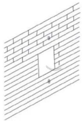

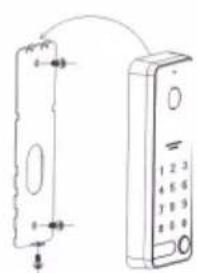
- Separate the mounting frame from the external panel.
- Drill two holes and fix the frame to the wall (post).
- Pass the wires through the hole in the mounting frame and connect them to the panel as shown in the wiring diagram.
- Attach the external panel to the frame.
- Screw the bottom screw of the external panel to the frame.
2. Surface mounting at an angle 30°
- Loosen the bottom screw on the external panel and separate the mounting frame from it.
- Fix the angle bracket and then the mounting frame to the wall with 2 screws.
- Pass the wires through the hole in the mounting frame and connect them to the panel as shown in the wiring diagram.
- Attach the external panel to the frame.
- Screw the bottom screw of the external panel to the frame.


Wiring diagram - proximity card and tag function
![graph TD A["OR-VID-EX-1061KV"] --> B["External Panel"] B --> C["Device Port ①"] C --> D["Port ②"] D --> E["Port ③"] E --> F["Port ④"] F --> G["Port ⑤"] G --> H["Port ⑥"] H --> I["Port ⑦"] I --> J["Port ⑧"] J --> K["Port ⑨"] K --> L["Port ⑩"] L --> M["Port ⑪"] M --> N["Port ⑫"] N --> O["Port ⑬"] O --…](/content/2026/05/893496/images/7cf10c97cbbd0216b206ad9be34033b1594af63bcb4233f723dba1e634e4d745.jpg)
For this connection, wires 10 and 11 (pink and grey) must be shorted!
The external panel cooperates with video monitors of VIBELL series. The set does not include an electric door opener and gate automatics.
While designing the wiring system, take into account the suitable cross-section of cables: up to 30 m - recommended cable XzTKMXpw 3 x 2 x 0.5 mm 2 from 30 m to 100 m - recommended cable XzTKMXpw 3 x 2 x 0.8 mm 2
The connection to the electromagnetic lock should be made with 2 x 1 mm 4 .
The set is compatible with any electric door strike with voltage of 12V DC (not included). When connecting, keep the correct polarity as shown in the diagram!
The total length of the installation must not exceed 100 meters. The use of twisted-pair cables is absolutely not recommended.
SAFETY PRECAUTIONS
Do not install the camera where the camera lens will be directly exposed to sunlight or strong lighting. If light falls directly on the lens of the outdoor camera, the image will be overexposed; white or only outlines will be visible. Do not use cleaning agents based on solvents, petrol, etc. or agents containing abrasive substances. Clean dirt only with a soft damp cloth and a small amount of detergent designed for cleaning plastic parts.
Wiring diagram with Wiegand control panel
![graph TD A["Central Wiegand"] -->|Pin ①| B["Remote Control"] A -->|Pin ②| C["Central Wiegand"] B --> D["10 Pin: Brown: Gate"] B --> E["10 Pin: Orange: COM"] B --> F["10 Pin: Green: NO"] B --> G["10 Pin: White: Video"] B --> H["10 Pin: Yellow: Power"] B --> I["10 Pin: Blue: GND"] B --> J["10 Pin: Red…](/content/2026/05/893496/images/262215983a898cb50194ec8dccbb20b3ade94d316c852bf86709679c71794233.jpg)
![graph TD A["Relay 12V DC, impedance coil > 700Ohm"] --> B["we NO COM"] B --> C["Gate control"] D["If there are problems with controlling the gate, we recommend using a 12V relay with a coil of minimum impedance 700Ohm"] --> B E["1. brown"] --> B F["5. yellow"] --> B](/content/2026/05/893496/images/d3c9207d2d53be6da585c68fdb68508845754431ce0c3a673ad5f6a0559faef3.jpg)
OPERATION OF DEVICE
IMPORTANT: When power is first applied, the keypad will enter MASTER card/tag logging mode.
When an intermittent beep-beep sounds from the external cassette, read the card/tag and mark it as MASTER.
1. Adding a proximity card/tag
To add a user card/tag, hold the master card/tag close to the reader, if the LEDs are illuminated load the user cards/tags one by one. When the card/tag is brought close to the reader, a beep will sound, indicating that the card/tag has been successfully registered.
When you have finished registering cards or tags, load the registered tag/card or do not take any action for about 30 seconds and the external panel will automatically exit the add new users function. Each time you want to add more new users, load the master card/tag first.
A maximum of 150 users can be added.
2. Deleting all users
Aby usunąć wszystkie zarejestrowane karty/breloki zbliż 4-krotnie kartę lub brelok główny do czytnika, a następnie zarejestruj nowe karty/breloki.
If a master card/tag is lost, disconnect the power and remove the rear cover of the external panel, connect the power and press the RST button (figure below). All user cards/tags will be deleted. The master card and user cards must be re-registered.

RESET button
3. Unlocking the door with the password
(1) Password change
Briefly press the change password button "*" and then enter the old unlock password on the numeric keypad (factory set password: 123456) and confirm with "#". Now enter the new unlock password and confirm again with "#". The password will be successfully changed after re-entering the new password.
Example: press "*" briefly, enter factory password: 123456, press "#", new password: 111111, press "#" and again new password: 111111, and again press "#". The password has been successfully changed.
Note: the new password can be up to 8 characters long.
(2) Door opening
Enter the password for unlocking on the numeric keypad and confirm with "#". The door lock will be unlocked.
TECHNICAL DATA
| 1 | Communication method | Headset-free |
| 2 | Connection type | 4 wires + 2 |
| 3 | Audio signal | 300mVp-p 300 Ohm |
| 4 | Video signal | 1Vp-p 75 Ohm |
| 5 | Camera | CVBS/720P/1080P |
| 6 | Night vision | IR backlighting |
| 7 | Minimum lighting | 0.1 LUX (0.5M) |
| 8 | Camera viewing angle | 110° (horizontal) 57° (vertical) |
| 9 | Operating mode | Touch screen keypad |
| 10 | Supply voltage | DC 12-15V from monitor |
| 11 | Power supply for the keypad, door opener | 12VDC, 1.5A |
| 12 | Reader range | 20mm |
| 13 | Maximum number of user cards | 150 pcs |
| 14 | Power consumption | 3W |
| 15 | Working temperature | -25° - +60° |
| 16 | Storage temperature | -30° - +60° |
| 17 | Ingress protection | IP65 |
| 18 | Dimensions | 55 x 152 x 22mm |
| 19 | Net weight | 0.226kg |
Each household is a user of electrical and electronic equipment, and hence a potential producer of hazardous waste for humans and the environment, due to the presence of hazardous substances, mixtures and components in the equipment. On the other hand, used equipment is valuable material from which we can recover raw materials such as copper, tin, glass, iron and others. The wee sign placed on the equipment, packaging or documents attached to it indicates the need for selective collection of waste electrical and electronic equipment. Products so marked, under penalty of fine, cannot be thrown into ordinary garbage along with other waste.
The marking means at the same time that the equipment was placed on the market after August 13, 2005. It is the responsibility of the user to hand the used equipment to a designated collection point for proper processing. Used equipment can also be handed over to the seller, if one buys a new product in an amount not greater than the new purchased equipment of the same type. Information on the available collection system of waste electrical equipment can be found in the information desk of the store and in the municipal office or district office. Proper handling of used equipment prevents negative consequences for the environment and human health!

ORNO-LOGISTIC Sp. z o.o.
ul. Rolników 437, 44-141 Gliwice tel. 32 43 43 110, www.orno.pl


- VIDEO KAMERA
- SAFETY NOTES
- EXTERNAL PANEL CONSTRUCTION
- MAIN FEATURES AND FUNCTIONS
- EXTERNAL PANEL INSTALLATION
- SURFACE MOUNTING
- SURFACE MOUNTING AT AN ANGLE 30°
- SAFETY PRECAUTIONS
- OPERATION OF DEVICE
- ADDING A PROXIMITY CARD/TAG
- DELETING ALL USERS
- UNLOCKING THE DOOR WITH THE PASSWORD
- PASSWORD CHANGE
- DOOR OPENING
Marke : VIBELL
Modell : OR-VID-EX-1061KV
Kategorie : Glocke