SR-19 - Empfänger MARANTZ - Kostenlose Bedienungsanleitung
Finden Sie kostenlos die Bedienungsanleitung des Geräts SR-19 MARANTZ als PDF.


| Produkttyp | AV-Surround-Receiver |
| Marke | Marantz |
| Modell | SR-19 |
| Abmessungen (B x H x T) | 458 mm x 190 mm x 496 mm |
| Gewicht | 22,0 kg |
| Stromversorgung | Wechselstrom 120 V, 60 Hz |
| Leistungsaufnahme (Stereo Nennleistung) | 440 W |
| Dauerausgangsleistung (Front, Center, Surround) | 110 W pro Kanal an 8 Ohm (20 Hz – 20 kHz) |
| Klirrfaktor (THD) Front | 0,05 % |
| Signal-Rausch-Abstand (Linear) | 105 dB |
| Eingänge (Analog) | CD, TAPE, CD-R/MD, TV, LD, DVD, VCR1, DSS/VCR2, AUX |
| Digitaleingänge | 4 (koaxial/optisch) |
| Digitalausgänge | 2 (für CD-R oder MD) |
| FM-Tunerbereich | 87,5 – 108,0 MHz |
| AM-Tunerbereich | 520 – 1710 kHz |
| Decodierformate | Dolby Digital, DTS, THX Cinema, Dolby Pro Logic, Stereo, Mono |
| Surround-Modi | Auto, Dolby, THX, DTS, Hall, Matrix, Movie, Stereo/Mono |
| Besondere Funktionen | Multi-Room, Sleep-Timer, OSD, Source Direct, 6-Kanal-Direkteingang |
| Fernbedienung | RC-18SR (lernfähig, LCD) |
| Mitgeliefertes Zubehör | Fernbedienung, 4 AA-Batterien, FM-Antenne, AM-Rahmenantenne, FM-Konverter |
Häufig gestellte Fragen - SR-19 MARANTZ
Benutzerfragen zu SR-19 MARANTZ
0 Frage zu diesem Gerät. Beantworten Sie die, die Sie kennen, oder stellen Sie Ihre eigene.
Eine neue Frage zu diesem Gerät stellen
Laden Sie die Anleitung für Ihr Empfänger kostenlos im PDF-Format! Finden Sie Ihr Handbuch SR-19 - MARANTZ und nehmen Sie Ihr elektronisches Gerät wieder in die Hand. Auf dieser Seite sind alle Dokumente veröffentlicht, die für die Verwendung Ihres Geräts notwendig sind. SR-19 von der Marke MARANTZ.
BEDIENUNGSANLEITUNG SR-19 MARANTZ
marantz®
Model SR-19 User Guide
AV Surround Receiver
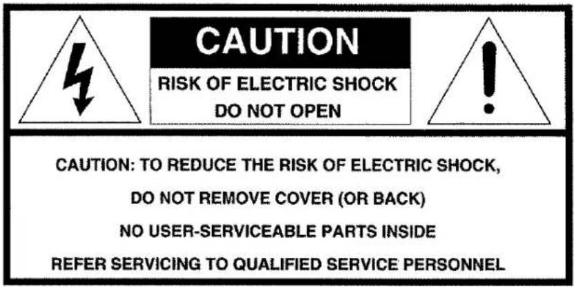
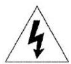
The lightning flash with arrowhead symbol, within an equilateral triangle, is intended to alert the user to the presence of uninsulated "dangerous voltage" within the product's enclosure that may be of sufficient magnitude to constitute a risk of electric shock to persons.
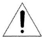
The exclamation point within an equilateral triangle is intended to alert the user to the presence of important operating and maintenance (servicing) instructions in the literature accompanying the appliance.
WARNING
TO REDUCE THE RISK OF FIRE OR ELECTRIC SHOCK, DO NOT EXPOSE THIS APPLIANCE TO RAIN OR MOISTURE.
CAUTION: TO PREVENT ELECTRIC SHOCK, MATCH WIDE BLADE OF PLUG TO WIDE SLOT, FULLY INSERT.
ATTENTION: POUR ÉVITER LES CHOCS ÉLECTRIQUES, INTRODUIRE LA LAME LA PLUS LARGE DE LA FICHE DANS LA BORNE CORRESPONDANTE DE LA PRISE ET POUSSER JUSQU'AU FOND.
NOTE TO CATV SYSTEM INSTALLER:
This reminder is provided to call the CATV (Cable-TV) system installer's attention to Article 820-40 of the NEC, that provides guidelines for proper grounding and, in particular, specified that the cable ground shall be connected to the grounding system of the building, as close to the point of cable entry as practical.
NOTE:
This equipment has been tested and found to comply with the limits for a Class B digital device, pursuant to Part 15 of the FCC Rules. These limits are designed to provide reasonable protection against harmful interference in a residential installation. This equipment generates, uses and can radiate radio frequency energy and, if not installed and used in accordance with the instructions, may cause harmful interference to radio communications. However, there is no guarantee that interference will not occur in a particular installation. If this equipment does cause harmful interference to radio or television reception, which can be determined by tuning the equipment off and on, the user is encouraged to try to correct the interference by one or more of the following measures:
- Reorient or relocate the receiving antenna.
- Increase the separation between the equipment and receiver.
- Connect the equipment into an outlet on a circuit different from that to which the receiver is connected.
- Consult the dealer or an experienced radio/TV technician for help.
NOTE:
Changes or modifications may cause this unit to fail to comply with Part 15 of the FCC Rules and may void the user's authority to operate the equipment.
IMPORTANT SAFETY INSTRUCTIONS
READ BEFORE OPERATING EQUIPMENT
This product was designed and manufactured to meet strict quality and safety standards. There are, however, some installation and operation precautions which you should be particularly aware of.
- Read Instructions - All the safety and operating instructions should be read before the appliance is operated.
- Retain Instructions-The safety and operating instructions should be retained for future reference.
- Heed Warnings-All warnings on the appliance and in the operating instructions should be adhered to.
- Follow Instructions-All operating and use instructions should be followed.
- Cleaning-Unplug this video product from the wall outlet before cleaning. Do not use liquid cleaners or aerosol cleaners. Use a damp cloth for cleaning.
- Attachments-Do not use attachments not recommended by the video product manufacturer as they may cause hazards.
- Water and Moisture-Do not use this video product near water-for example, near a bath tub, wash bowl, kitchen sink, or laundry tub, in a wet basement, or near a swimming pool, and the like.
- Accessories-Do not place this video product on an unstable cart, stand, tripod, bracket, or table. The video product may fall, causing serious injury to a child or adult, and serious damage to the appliance. Use only with a cart, stand, tripod, bracket, or table recommended by the manufacturer, or sold with the video product. Any mounting of the appliance should follow the manufacturer's instructions, and should use a mounting accessory recommended by the manufacturer.
- Ventilation-Slots and openings in the cabinet are provided for ventilation and to ensure reliable operation of the video product and to protect it from overheating, and these openings must not be blocked or covered. The openings should never be blocked by placing the video product on a bed, sofa, rug, or other similar surface. This video product should never be placed near or over a radiator or heat register. This video product should not be placed in a built-in installation such as a bookcase or rack unless proper ventilation is provided or the manufacturer's instructions have been adhered to.
-
Power Sources-This video product should be operated only from the type of power source indicated on the marking label. If you are not sure of the type of power supply to your home, consult your appliance dealer or local power company. For video products intended to operate from battery power, or other sources, refer to the operating instructions.
-
Grounding or Polarization-This video product is equipped with a polarized alternating-current line plug (a plug having one blade wider than the other). This plug will fit into the power outlet only one way. This is a safety feature. If you are unable to insert the plug fully into the outlet, try reversing the plug. If the plug should still fail to fit, contact your electrician to replace your obsolete outlet. Do not defeat the safety purpose of the polarized plug.
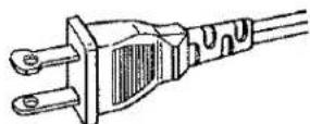
AC POLARIZED PLUG
- Power-Cord Protection-Power-supply cords should be routed so that they are not likely to be walked on or pinched by items placed upon or against them, paying particular attention to cords at plugs, convenience receptacles, and the point where they exit from the appliance.
- Protective Attachment Plug - The appliance is equipped with an attachment plug having overload protection. This is a safety feature. See Instruction Manual for replacement or resetting of protective device. If replacement of the plug is required, be sure the service technician has used a replacement plug specified by the manufacturer that has the same overload protection as the original plug.
- Outdoor Antenna Grounding-If an outside antenna or cable system is connected to the video product, be sure the antenna or cable system is grounded so as to provide some protection against voltage surges and built up static charges. Section 810 of the National Electrical Code, ANSI/NFPA No. 70-1984, provides information with respect to proper grounding of the mast and supporting structure, grounding of the lead-in wire to an antenna discharge unit, size of grounding conductors, location of antenna-discharge unit, connection to grounding electrodes, and requirements for the grounding electrode. See Figure 1.
- Lightning-For added protection for this video product receiver during a lightning storm, or when it is left un-attended and unused for long periods of time, unplug it from the wall outlet and disconnect the antenna or cable system. This will prevent damage to the video product due to lightning and power-line surges.
- Power Lines-An outside antenna system should not be located in the vicinity of overhead power lines or other electric light or power circuits, or where it can fall into such power lines or circuits. When installing an outside antenna system, extreme care should be taken to keep from touching such power lines or circuits as contact with them might be fatal.
- Overloading-Do not overload wall outlets and extension cords as this can result in a risk of fire or electric shock.
-
Object and Liquid Entry-Never push objects of any kind into this video product through openings as they may touch dangerous voltage points or short-out parts that could result in a fire or electric shock. Never spill liquid of any kind on the video product.
-
Servicing-Do not attempt to service this video product yourself as opening or removing covers may expose you to dangerous voltage or other hazards. Refer all servicing to qualified service personnel.
- Damage Requiring Service-Unplug this video product from the wall outlet and refer servicing to qualified service personnel under the following conditions:
a. When the power-supply cord or plug is damaged.
b. If liquid has been spilled, or objects have fallen into the video product.
c. If the video product has been exposed to rain or water.
d. If the video product does not operate normally by following the operating instructions. Adjust only those controls that are covered by the operating instructions as an improper adjustment of other controls may result in damage and will often require extensive work by a qualified technician to restore the video product to its normal operation.
e. If the video product has been dropped or the cabinet has been damaged. -
When the video product exhibits a distinct change in performance—this indicates a need for service.
-
Replacement Parts-When replacement parts are required, be sure the service technician has used replacement parts specified by the manufacturer or have the same characteristics as the original part. Unauthorized substitutions may result in fire, electric shock or other hazards.
- Safety Check-Upon completion of any service or repairs to this video product, ask the service technician to perform safety checks to determine that the video product is in proper operating condition.
- Carts and Stands-The appliance should be used only with a cart or stand that is recommended by the manufacturer.
- An appliance and cart combination should be moved with care. Quick stops, excessive force, and uneven surfaces may cause the appliance and cart combination to overturn.
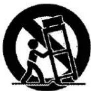
FIGURE 1
EXAMPLE OF ANTENNA GROUNDING ACCORDING TO
NATIONAL ELECTRICAL CODE INSTRUCTIONS
CONTAINED IN ARTICLE 810 - "RADIO AND TELEVISION EQUIPMENT"
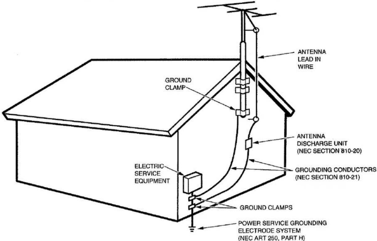
NEC - NATIONAL ELECTRICAL CODE
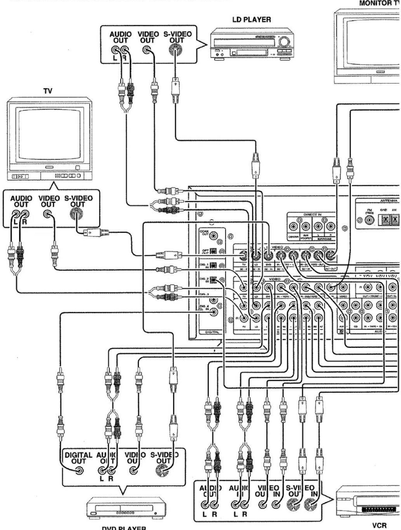
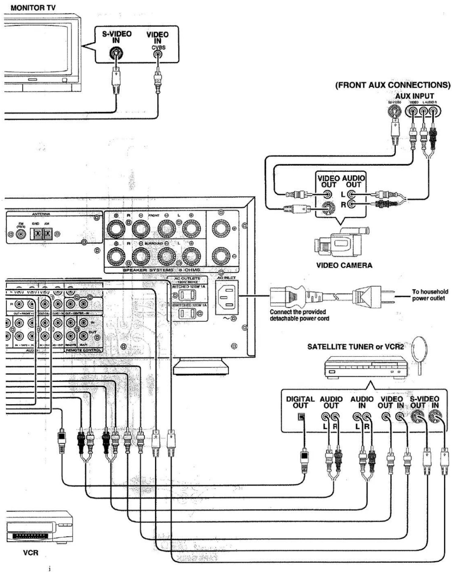
VIDEO SYSTEM CONNECTIONS FOR VIDEO COMPONENTS
flowchart
graph TD
    TV["TV"] --> AudioOut["Audio OUT"]
    AudioOut --> VideoOut["Video OUT"]
    VideoOut --> SVideoOut["S-VIDEO OUT"]
    SVideoOut --> AudioOut
    AudioOut --> VideoOut
    VideoOut --> SVideoOut
    SVideoOut --> AudioOut
    AudioOut --> VideoOut
    VideoOut --> SVideoOut
    SVideoOut --> AudioOut
    AudioOut --> VideoOut
    VideoOut --> SVideoOut
    SVideoOut --> AudioOut
    AudioOut --> VideoOut
    VideoOut --> SVideoOut
    SVideoOut --> AudioOut
    AudioOut --> VideoOut
    VideoOut --> SVideoOut
    SVideoOut --> AudioOut

    LDPLAYER["LD PLAYER"]
    VCR["VCR"]
    MONITOR["T1"]
    DVDPLAYER["DVD PLAYER"]

    A["TV"] --> AudioOut
    A --> VideoOut
    A --> SVideoOut
    B["MONITOR T1"] --> AudioOut
    B --> VideoOut
    B --> SVideoOut
    C["TV"] --> AudioOut
    C --> VideoOut
    C --> SVideoOut
    D["MONITOR T1"] --> AudioOut
    D --> VideoOut
    D --> SVideoOut
    E["TV"] --> AudioOut
    E --> VideoOut
    E --> SVideoOut
    F["MONITOR T1"] --> AudioOut
    F --> VideoOut
    F --> SVideoOut
    G["TV"] --> AudioOut
    G --> VideoOut
    G --> SVideoOut
    H["MONITOR T1"] --> AudioOut
    H --> VideoOut
    H --> SVideoOut
    I["TV"] --> AudioOut
    I --> VideoOut
    I --> SVideoOut
    J["MONITOR T1"] --> AudioOut
    J --> VideoOut
    J --> SVideoOut
    K["TV"] --> AudioOut
    K --> VideoOut
    K --> SVideoOut
    L["MONITOR T1"] --> AudioOut
    L --> VideoOut
    L --> SVideoOut
    M["TV"] --> AudioOut
    M --> VideoOut
    M --> SVideoOut
    N["MONITOR T1"] --> AudioOut
    N --> VideoOut
    N --> SVideoOut
    O["TV"] --> AudioOut
    O --> VideoOut
    O --> SVideoOut
    P["MONITOR T1"] --> AudioOut
    P --> VideoOut
    P --> SVideoOut
    Q["TV"] --> AudioOut
    Q --> VideoOut
    Q --> SVideoOut
    R["MONITOR T1"] --> AudioOut
    R --> VideoOut
    R --> SVideoOut
    S["TV"] --> AudioOut
    S --> VideoOut
    S --> SVideoOut
    T["MONITOR T1"] --> AudioOut
    T --> VideoOut
    T --> SVideoOut
    U["TV"] --> AudioOut
    U --> VideoOut
    U --> SVideoOut
    V["MONITOR T1"] --> AudioOut
    V --> VideoOut
    V --> SVideoOut
    W["TV"] --> AudioOut
    W --> VideoOut
    W --> SVideoOut
    X["MONITOR T1"] --> AudioOut
    X --> VideoOut
    X --> SVideoOut
flowchart
graph TD
    A["MONITOR TV"] --> B["S-VIDEO IN"]
    A --> C["VIDEO IN CVBS"]
    B --> D["Speaker Systems & CHMS"]
    C --> D
    D --> E["AC OUTLETS 130W 50Hz Switched 150W 1A"]
    D --> F["AD INLET"]
    E --> G["SATELLITE TUNER or VCR2"]
    F --> G
    G --> H["Digital OUT"]
    G --> I["AUDIO OUT"]
    G --> J["AUDIO IN"]
    G --> K["VIDEO OUT IN"]
    G --> L["S-VIDEO OUT IN"]
    style A fill:#f9f,stroke:#333
    style B fill:#ccf,stroke:#333
    style C fill:#ccf,stroke:#333
    style D fill:#cfc,stroke:#333
    style E fill:#fcc,stroke:#333
    style F fill:#fcc,stroke:#333
    style G fill:#cff,stroke:#333
    style H fill:#ffc,stroke:#333
    style I fill:#ffc,stroke:#333
    style J fill:#ffc,stroke:#333
    style K fill:#ffc,stroke:#333
    style L fill:#ffc,stroke:#333
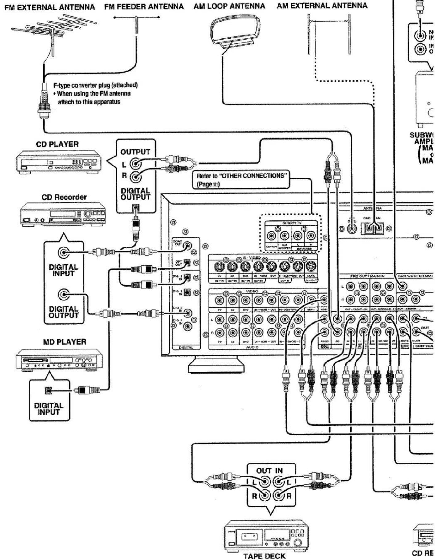
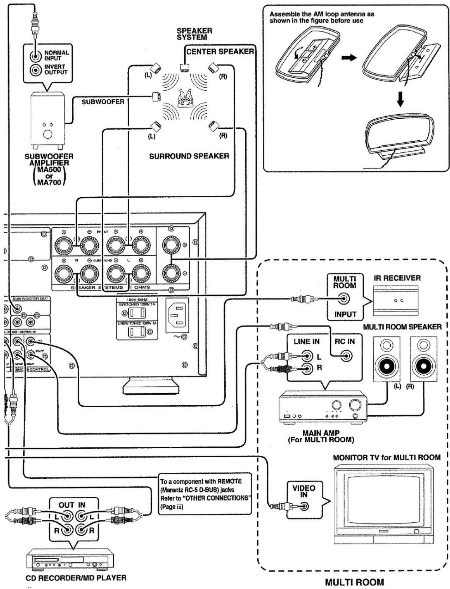
AUDIO SYSTEM CONNECTIONS FOR AUDIO COMPONENTS
flowchart
graph TD
    A["FM EXTERNAL ANTENNA"] --> B["F-type converter plug (attached) \nWhen using the FM antenna attach to this apparatus"]
    C["CD PLAYER"] --> D["OUTPUT L R DIGITAL OUTPUT"]
    E["CD Recorder"] --> F["Digital INPUT"]
    G["MD PLAYER"] --> H["Digital INPUT"]
    I["TAPE DECK"] --> J["OUT IN L R"]
    K["SUBW AMPL MA MA"] --> L["Refer to "OTHER CONNECTIONS" (Page iii)"]
    M["AM LOOP ANTENNA"] --> N["DIRECT IN CENTER"]
    O["AM EXTERNAL ANTENNA"] --> P["OUT OUT MAIN IN SUBWOOFER OUT"]
    Q["TAPE DECK"] --> R["OUT IN L R"]
    S["CD RE"] --> T["CD RE"]
    style A fill:#f9f,stroke:#333
    style C fill:#f9f,stroke:#333
    style E fill:#f9f,stroke:#333
    style G fill:#f9f,stroke:#333
    style I fill:#f9f,stroke:#333
    style K fill:#f9f,stroke:#333
flowchart
graph TD
    A["CD RECORDER/MD PLAYER"] --> B["OUT IN"]
    B --> C["R"]
    C --> D["L"]
    D --> E["R"]
    E --> F["To a component with REMOTE (Marantz RC-5 D-BUS) jacks Refer to "OTHER CONNECTIONS" (Page iii)"]
    F --> G["VIDEO IN"]
    G --> H["MONITOR TV for MULTI ROOM"]
    H --> I["MULTI ROOM"]
    I --> J["MAIN AMP (For MULTI ROOM)"]
    J --> K["LINE IN L R"]
    K --> L["MULTI ROOM SPEAKER"]
    L --> M["IR RECEIVER INPUT"]
    M --> N["MULTI ROOM"]
    N --> O["SURROUND SPEAKER"]
    O --> P["SURBOOFER AMPLIFIER (MA500 or MA700)"]
    P --> Q["SUBWOOFER"]
    Q --> R["NORMAL INPUT INVERT OUTPUT"]
    R --> S["Speaker SYSTEM CENTER SPEAKER"]
    S --> T["ASSEMBLE THE AM loop antenna as shown in the figure before use"]
    T --> U["Image of device with sensor input"]
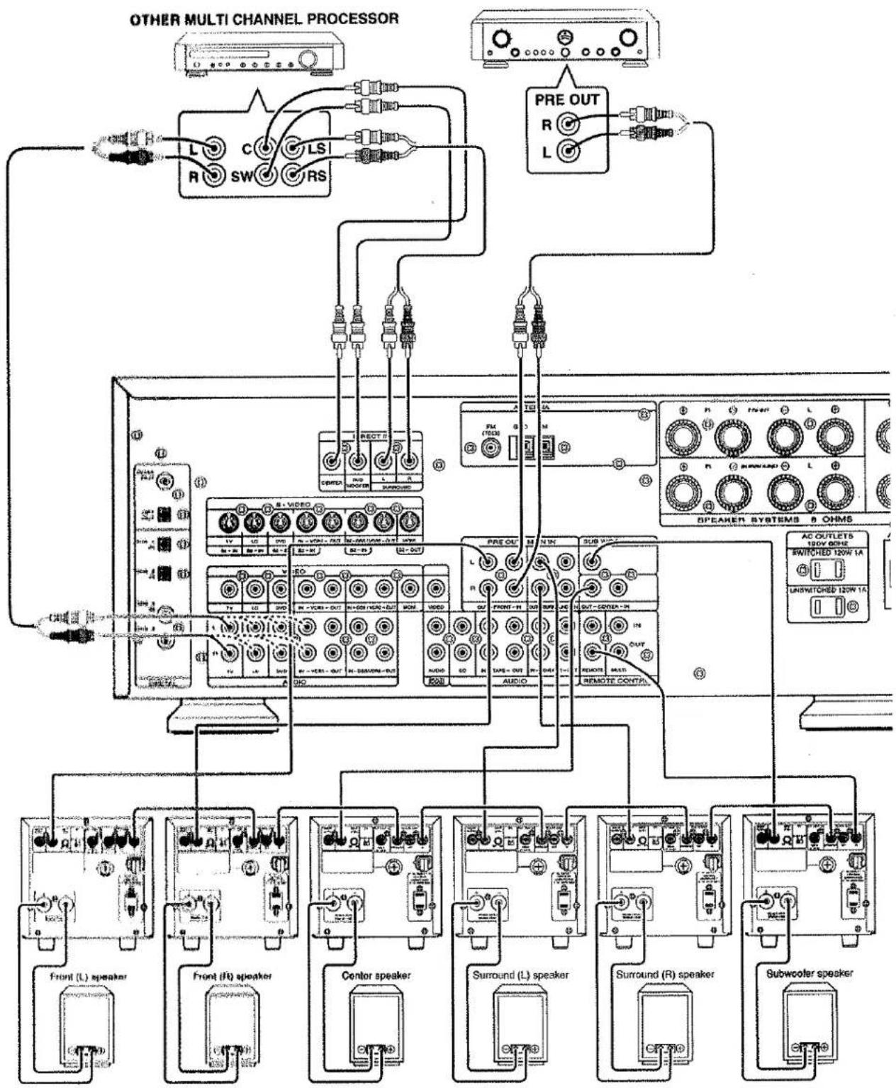
OTHER CONNECTIONS
flowchart
graph TD
    A["OTHER MULTI CHANNEL PROCESSOR"] --> B["L"]
    A --> C["C"]
    A --> D["RS"]
    A --> E["LSI"]
    A --> F["R"]
    A --> G["SW"]
    A --> H["RS"]
    I["PRE OUT"] --> J["R"]
    I --> K["L"]
    B --> L["Speaker Systems 8 OHMS"]
    C --> M["Speaker Systems 8 OHMS"]
    D --> N["Speaker Systems 8 OHMS"]
    E --> O["Speaker Systems 8 OHMS"]
    F --> P["Speaker Systems 8 OHMS"]
    G --> Q["Speaker Systems 8 OHMS"]
    L --> R["AC OUTLETS 120W 1A"]
    L --> S["Switched 120W 1A"]
    L --> T["Unswitched 120W 1A"]
    M --> U["AC OUTLETS 120W 1A"]
    M --> V["Switched 120W 1A"]
    M --> W["Unswitched 120W 1A"]
    N --> X["AC OUTLETS 120W 1A"]
    N --> Y["Switched 120W 1A"]
    N --> Z["Unswitched 120W 1A"]
    O --> AA["AC OUTLETS 120W 1A"]
    O --> AB["Switched 120W 1A"]
    O --> AC["Unswitched 120W 1A"]
    P --> AD["AC OUTLETS 120W 1A"]
    P --> AE["Switched 120W 1A"]
    P --> AF["Unswitched 120W 1A"]
    Q --> AG["AC OUTLETS 120W 1A"]
    Q --> AH["Switched 120W 1A"]
    Q --> AI["Unswitched 120W 1A"]
    R --> AJ["AC OUTLETS 120W 1A"]
    R --> AK["Switched 120W 1A"]
    R --> AL["Unswitched 120W 1A"]
    S --> AM["AC OUTLETS 120W 1A"]
    S --> AN["Switched 120W 1A"]
    S --> AO["Unswitched 120W 1A"]
    T --> AP["AC OUTLETS 120W 1A"]
    T --> AQ["Switched 120W 1A"]
    T --> AR["Unswitched 120W 1A"]
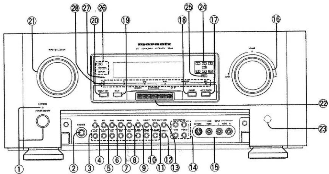
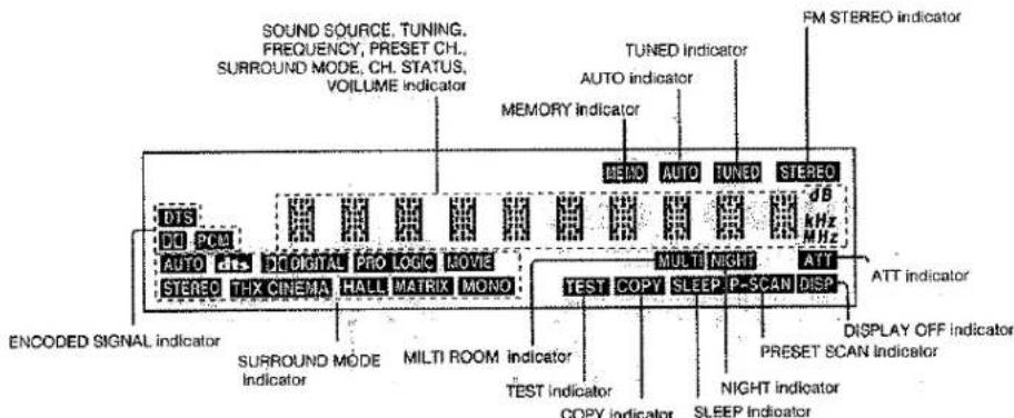
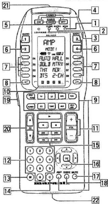
TABLE OF CONTENTS
INTRODUCTION....5
DESCRIPTION....
FEATURES
FRONT PANEL FEATURES 4
REMOTE CONTROL UNIT RC-18SR 5
OPERATION OF REMOTE CONTROL UNIT
SET-UP
ON-SCREEN MENU SYSTEM
OSD MAIN MENU
SYSTEM SETUP
SPEAKER SETUP AND LEVELS
SURROUND MODE
REC COPY
MULTI ROOM SELECT ....
STATION NAME INPUT
BASIC OPERATION ....
LISTENING TO THE TUNER 12
PLAYBACK OPERATION
OTHER FUNCTIONS....14
MULTI ROOM SELECTOR
TV AUTO ON/OFF FUNCTION
SETTING THE SLEEP TIMER (ONLY REMOTE CONTROL UNIT)....14
REMOTE CONTROL UNIT RC-18SR 15
FUNCTION AND OPERATION 15
RC-18SR BASIC OPERATION .... 16
ADVANCED PROGRAMMING TECHNIQUES 20
OTHER FUNCTIONS ....
DIRECT COMMAND FUNCTIONS LISTING
SURROUND MODES 29
TROUBLESHOOTING....31
TECHNICAL SPECIFICATIONS ....38
INTRODUCTION
Thank you for purchasing the Marantz SR-19 THX/ DTS/Dolby Digital Surround receiver. This remarkable component has been engineered to provide you with many years of home theater enjoyment. Please take a few minutes to read this manual thoroughly before you connect and operate the SR-19. As there are a number of connection and configuration options, you are encouraged to discuss your own particular home theater setup with your Marantz A/V specialist dealer.
DESCRIPTION

DTS Technology was found in 1994 to commercialize 5.1 channels of discrete digital audio into home theater systems. The DTS brings you premiere quality and discrete multi-channel digital sound to movies. The DTS playback unit is a motion picture sound system designed to create full range digital sound reproduction using a theater's existing audio system.
The no compromise DTS digital process sets the standard of quality for cinema sound by delivering an exact copy of the studio master recordings to neighborhood theaters. Now, every moviegoer can hear the sound exactly as the moviemaker intended.
The Dolby Digital surround system lets you enjoy Digital TV, Digital Satellite Receiver as well as DVD, LD software in digital surround, which is the next step above Dolby Pro Logic. In comparison with Dolby Pro Logic, Dolby Digital provides separate left surround and right surround channels, for more precise localization of sounds and a more convincing, realistic ambience. And, with Dolby Digital, all five main channels are full ranges and a subwoofer can be added to each channel, if desired. By providing up to 5.1 channels of digital audio independently, Dolby Digital lets you enjoy better sound quality and more powerful presence than conventional Dolby Surround.
THX® is an exclusive set of standards and technologies established by the world-renowned film production company, Lucasfilm Ltd. THX resulted from George Lucas' desire to reproduce the movie soundtrack as faithfully as possible both in the movie theater and in the home theater.
THX engineers developed patented technologies to accurately translate the sound from a movie theater environment into the home, correcting the tonal and spatial errors that occur. When the THX mode of the SR-19 is on, three distinct THX technologies are automatically added:
Re-Equalization-restores the correct tonal balance for watching a movie in a home environment. These sounds are otherwise mixed to be brighter for a large movie theater. Re-EQ compensates for this and prevents the soundtracks from being overly bright and harsh when played in a home theater.
Timbre Matching-filters the information going to the surround speakers so they more closely match the tonal characteristics of the sound coming from the front speakers. This ensures seamless panning between the front and surround speakers.
Adaptive Decorrelation-slightly changes one surround channel's time and phase relationship with respect to the other surround channel. This expands the listening position and creates with only two surround speakers the same spacious surround experience as in a movie theater with multiple surround speakers.
The Marantz SR-19 was required to pass a rigorous series of quality and performance tests, in addition to incorporating the technologies explained above, in order to be THX Select certified by Lucasfilm Ltd.
THX Select requirements cover every aspect of performance including pre-amplifier and power amplifier performance and operation, and hundreds of other parameters in both the digital and analog domain.
Movies which have been encoded in Dolby Digital, DTS, Dolby Pro Logic, stereo and Mono will all benefit from the THX mode when being viewed. The THX mode should only be activated when watching movies which were originally produced for a movie theater environment. THX need not be activated for music, movies made especially for TV, or shows such as sports programming, talk shows, etc. This is because they were originally mixed for a small room environment.
"Dolby", "AC-3", "Pro Logic" and the double-D symbol are trademarks of Dolby Laboratories.
"DTS" and "DTS Digital Surround" are trademarks of Digital Theater Systems, Inc.
"Lucasfilm" and "THX" are registered trademarks of Lucasfilm Ltd.
FEATURES
● High quality DTS/Dolby Digital (AC-3) DSP decoding chip.
● High quality THX DSP decoding chip.
● 4 Digital inputs, for connection to other sources, such as DVD, DSS, CD or LD.
● 2 Digital outputs for connection to CD-R or MD.
◆ Digital Dolby Pro Logic decoding provides wide dynamic range, low distortion, and high imaging accuracy.
● 96 kHz PCM Digital Audio reproduced by STEREO.
- Integral AM/FM tuner.
● On Screen Display with Composite and "S" video.
- Composite and "S" video switching.
- Separate dedicated Multi-Room stereo pre-amp outputs and composite provide for dual zone independent operation.
- Infrared remote control with learning capability.
FRONT PANEL FEATURES (SEE PAGE 1)
① POWER switch and STANDBY indicator
You can turn on and off the unit's power using the front panel power switch. However, if you turn the unit off with the front panel switch, the unit goes completely off rather than to the "standby mode" (red LED indicator light glows in the standby mode). The unit cannot be turned on with the remote control when it is not in the standby mode. When the red LED is on, the unit can be turned on via the remote control or by pressing any input selector button on the front panel.
② PHONES jack for stereo headphones
Conventional dynamic headphones can be plugged in here.
Notes:
When the headphones plug is inserted, the surround mode is switched automatically to STEREO and the sound from the speakers is muted.
The surround mode returns to the previous mode as soon as the plug is removed from the jack.
③ Surround MODE buttons
(AUTO, DOLBY, THX, DTS, HALL, MATRIX, MOVIE, STEREO/MONO)
Selects the surround modes.
When these buttons are pressed, the SURROUND mode is changed.
④ A/D (ANALOG/DIGITAL) selector button
In case that you select the input source which is linked with any digital input, if you desire to switch to analog input temporarily, you can switch by pressing A/D key.
Note:
This key is not effective for an input source which is not linked with any digital input.
⑤ ATT (Attenuate) button
Press this button to attenuate the analog AUDIO signal selected with the FUNCTION buttons. When the analog input signal is too great and the voice distorts even by throttling the SR-19 VOLUME control, turn on the function. "ATT" is displayed when this function is activated.
The signal-input level is reduced by about half. The attenuate function will not have any effect on signals being output by the "REC OUT(TAPE, CD-R/MD, VCR1 and DSS/VCR2)" rear panel jacks.
This function is memorized for each input function.
⑥ BAND (Tuner Band Selector) button
Press this button to switch between FM mode and AM mode of the tuner.
Tuner band is changed in the following sequence.
FM → AM → FM → ...
⑦ FM MODE button
Press this button to select the auto stereo mode or mono mode when the FM band is selected. The AUTO indicator lights in the auto stereo mode.
⑧ MEMO (memory) button
Press this button to enter the luner preset memory numbers and station names.
⑨ CL (Clear) button
Press this button to cancel the station-memory setting mode or preset scan tuning.
⑩ D. (Digital) COPY button
Press this button for digital dubbing to the CD-R recorder or MD deck.
When this button is pressed, the digital source of the DIGITAL OUTPUT is switched in the following sequence.

⑪ TAPE COPY button
Press this button for audio dubbing to the tape deck.
When this button is pressed, the source of the TAPE OUT is switched in the following sequence.

⑫ S. (SOURCE) DIRECT button
Press this button to make higher quality Hi-Fi sounds. When this button is pressed, the signals are transmitted by bypassing the tone control circuitry so that they can be reproduced with higher quality.
Notes:
The surround mode is switched automatically to STEREO when the source direct function is turned on.
The source direct function is available with a digital source when the input signal is the PCM.
If a Dolby Digital signal or DTS signal input to SR-19, in this mode output from SR-19 will be muted.
⑬ VCR1 COPY button
Press this button for video and audio dubbing to the VCR1 deck.
When this button is pressed, the source of the VCR1 OUT is switched in the following sequence.

⑭ BASS and TREBLE tone controls
These controls are used to boost or cut high and low frequencies. TREBLE: Adjusts the tone of high-frequency sound.
BASS: Adjusts the tone of low-frequency sound.
Notes:
These buttons are unavailable in THX CINEMA mode. The frequency is flat by pressing the up and down keys simultaneously.
⑮ AUX input jacks
These auxiliary video/audio input jacks accept the connection of a camcorder, portable VCR, etc.
To make proper connections, refer to the owner's manuals of the auxiliary components.
⑯ VOLUME control knob
Adjusts the overall sound level. Turning the control clockwise increases the sound level.
⑰ AUTO TUNING button
When this button is pressed and the GYRO TUNING knob is turned quickly, the frequency is scanned while turning the GYRO TUNING knob. The Auto scan function starts when the GYRO TUNING knob is stopped:
⑱ PRESET button
Press this button to display the preset number. The preset number is changed by turning the GYRO TUNING knob.
⑲ MULTI (Multi Room) button
Press this button to switch the unit to multi room mode.
"MULTI ROOM" appears in the display.
⑳ DISPLAY OFF button
When this button is pressed, the display is turned off and the display off indicator lights up (DISP). Press this button again to turn the display ON again.
②1 INPUT SELECTOR knob
When this knob is turned, the input signal is switched in the following sequence.

flowchart
graph LR
    TUNER --> CD
    CD --> TAPE
    TAPE --> CD-R/MD
    CD-R/MD --> TV
    TV --> DVD
    DVD --> VCR
    VCR --> DSS/VCR2
    DSS/VCR2 --> AUX
    AUX --> CD
    CD --> TAPE
    TAPE --> CD-R/MD
    CD-R/MD --> TV
This knob can also be used to turn the unit's power on when it is in the standby mode.
②2 GYRO TUNING knob
Turn this knob to change the frequency or the preset number. The station name can be selected with this knob.
②3 INFRARED SENSOR window
This window receives infrared signals from the remote control unit.
②4 ENCODED CHANNEL STATUS indicator
These indicators show which channels are encoded with a digital input signal.
If the selected digital input signal is Dolby Digital 5.1ch or DTS 5.1ch, "L", "C", "R", "LS", "RS" and "LFE" will light up.
If the digital input signal is 2 channel PCM-audio, "L" and "R" will be displayed.
Note:
These indicators are depend on the digital input, without reference to the surround mode.
⑲ PEAK indicator
This indicator is a monitor for analog audio input signal. If the selected analog audio input signal is greater than the capable level of internal processing, this indicator will show. If this indicator is lit up, you should press the ATT button.
②6 DTS CINEMA and MUSIC indicator
These indicators display the currently selected DTS mode. If you select DTS cinema or DTS-music by surround mode button, these indicators will display.
⑳ 96 kHz decode indicator
This indicator is for 96 kHz PCM digital input signal. If the selected digital input signal is 96 kHz PCM audio, this indicator will illuminate.
⑳ VIDEO SOURCE indicator
Indicates video source currently selected.
REMOTE CONTROL UNIT RC-18SR
This chapter describes the functions which need to control the SR-19. See page 25 and following pages to refer other function of the RC-18SR.
4 POWER ON and OFF
These two buttons are use for turning on or off SR-19.
7 DIRECT button
The DIRECT command buttons (4 on each side of the LCD display, 8 total) work with the PAGE buttons (4 pages for each source component) to provide up to 32 dedicated specialized functions for each of the 11 function input selectors. Each DIRECT function may also be provided with an alphanumeric function indicator visible in the LCD display. Press the AMP or TUNER button 9 to control the receiver.
Press one of these buttons to select a surround mode for the current listening session.
| AMP | ||
| MODE1 | 1 AUTO | Auto select surround modes |
| 2 DOLB | Dolby Digital or Pro Logic decoding | |
| 3 THX | THX cinema decoding | |
| 4 DTS | DTS-cinema or DTS-music | |
| 5 HALL | Hall surround sound | |
| 6 MTRX | Matrix surround sound | |
| 7 MOV | Movie surround sound | |
| 8 2-CH | Stereo sound (no surround) | |
| MODE2 | 1 A/D | analog / digital select switchSwitches between the analog input and the digital input. |
| 2 DIR | source direct switchWhen this switch is pressed, the signals are transmitted by bypassing the tone control circuitry so that they can be reproduced with higher quality. | |
| 3 ATT | attenuate for analog input | |
| 4 OSD | on screen displayOnce the button is pressed, the on-screen display is turned on and each a control button related to the SR-19 is pressed thereafter, the information will be displayed on the TV screen. When the button is pressed again to turn the on-screen display off, it disappears from the TV screen. (Refer to "ON-SCREEN MENU SYSTEM" on page 8.) | |
| 5 MONO | monaural decodingWhen this button is pressed, the monaural sound is selected. | |
| 6 3-D | 3-D surround decodingThis button is not used for SR-19. | |
| 7 NITE | NIGHT mode for Dolby Digital | |
| Pressing this button prevents the Dolby Digital signal from playback at a loud voice. This function reduces the voice by 1/3 to 1/4 at maximum. Thus, it eliminates the occurrence of an abruptly loud voice at night. However, the function is valid only for the case when the Dolby Digital signal (AC-3) is entered into digital input and data to compress the voice exists in the signal to be played back. | ||
| 8 MLTI | activates multi-room mode | |
| MODE3 | 1 TRB+ | increases treble |
| 2 TRB- | decreases treble | |
| 3 BAS+ | increases bass | |
| 4 BAS- | decreases bassThe button 1 to 4 are used to control the tone. | |
| 5 R-EQ | activates RE-EQ functionThis button is not used for SR-19. | |
| 6 CH+ | channel select buttonPress this button to adjust the volume levels of the front, center, surround, subwoofer channels. Each press of the button changes the channel which can be adjusted. | |
| MODE3 | 7 LVL+ | increases channel level volume |
| 8 LVL- | decreases channel level volumeAfter pressing the CH+ button, use the LVL+ and LVL- buttons to adjust the volume level of each speaker channel. | |
| Note: These level controls are for temporary adjustment, so these setup is not memorized for each source. | ||
| PROCESSOR | 1 VOL+ | increases external decoder's volumeThis button is not used for SR-19. |
| 2 VOL- | decreases external decoder's volumeThis button is not used for SR-19. | |
| 3 6-CH | 6 channel direct buttonWhen the surround processor is connected to the DIRECT IN JACKS, press this button to play it. | |
| 4 BYP | bypasses external processor's decoding | |
| 5 SLEP | sleep timer buttonThis button is used for setting the sleep timer. | |
| 6 DISP | display off functionWhen this button is pressed, the display is turned off. | |
| 7 MODE | surround mode select buttonThis button is not used for SR-19 | |
| 8 PHNO | phono function buttonThis button is not used for SR-19. | |
| TUNER | ||
| BAND | 1 FM | FM band button |
| 2 AM | AM/MW band button | |
| 3 LW | long wave band buttonThis button is not used for SR-19 | |
| 4 BAND | selects radio band button | |
| 5 MODE | mono/stereo/muting mode selector button | |
| 6 TIME | time display buttonThis button is not used for SR-19 | |
| 7 F/P | frequency or preset channel display select buttonThis button is not used for SR-19 | |
| 8 SCAN | preset scan button | |
8 PAGE buttons
These buttons are used to select any 1 of the 4 pages of 8 functions for each DIRECT button, as explained above.
9 FUNCTION buttons
These buttons are used for selecting the input function. Press one of these buttons twice within 2 seconds.
11 VOLUME UP (+) AND DOWN (-)
These buttons are used to raise and lower the main system volume level.
12 TEN KEYPAD
They are useful for tuning a pre-set radio station and setting a station name.
13 M (MEMO) button
This button is used to enter the tuner preset memory numbers and station names.
14 C (Clear) button
This button is used to cancel certain memory or programming operations.
16 CURSOR buttons
The cursor buttons can be used to navigate within on-screen menus. These buttons are unavailable when the mode is set to DSS, TV or DVD.
17 MUTE button
This button can be used to mute the sound temporarily.
19 LIGHTING button
This button is used to activate the back-lit LCD screen and back-lit keys.
OPERATION OF REMOTE CONTROL UNIT
1. Remote control
The distance between the transmitter of the remote control unit and the IR SENSOR of the SR-19 should be less than about 5 meters. If the transmitter is pointed to a direction other than the IR SENSOR or if there is an obstacle between them, remote control may not be possible.
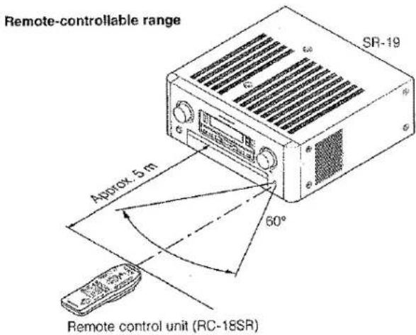
2. Loading batteries
The life of the batteries used with the remote control unit is about 4 months with normal use. Also be sure to replace batteries earlier when you notice that they are getting weak.
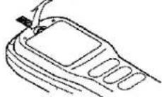
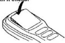
(1) Remove the back cover.
(2) Insert the alkaline batteries (AA type) with correct (+) and (-) polarity.
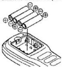
(3) Close until it clicks.
- Receiving the remote control codes
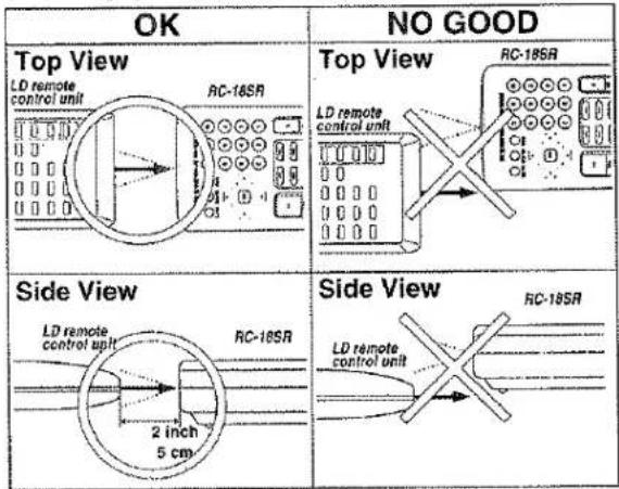
The RC-18SR can learn most of the remote control codes from various equipment, it learns the full word length of the code it is receiving. Due to the sensitivity of the receiving LED the RC-18SR may also "learn" noise from fluorescent lights, etc. which can quickly fill up the memory of the RC-18SR. In order to maximize the memory capacity of the RC-18SR please pay close attention to the following:
(1) Aim the transmitting remote control at a direct line of sight to the RC-18SR remote receiver eye.
(2) Keep 2 inches between transmitting remote and the RC-18SR receiving eye.
SET-UP
ON-SCREEN MENU SYSTEM
The SR-19 incorporates an on-screen menu system, which makes various operations possible by using the cursor and OK buttons on the remote unit.
The settings made with these buttons are also shown in the on-screen display.
OSD MAIN MENU
OSD MAIN MENU
SURROUND MODE
REC COPY
MULTI ROOM SELECT
STATION NAME INPUT
SYSTEM SETUP
SPKR SETUP / LEVELS
EXIT
SURROUND MODE
SURROUND MODE
MODE : STEREO
NIGHT MODE : OFF
LFE LEVEL : OdB
RETURN TO MAIN/EXIT
SYSTEM SETUP 1/2
| Input | Dig1234 | Ana |
| CD | □--- | - |
| TAPE | ---- | ■ |
| CD-R/MD | ----■ | - |
| TV | ---- | ■ |
| LD | ---- | - |
| DVD | ----■ | - |
| VCR1 | ---- | ■ |
| DSS/VCR2 | ----■ | - |
| TO OTHER SYSTEM SETUP | ||
SETUP 1/2
SETUP 1/2 SPKR SETUP
SETUP UNLOCKED
FRONT CH : SMALL/THX
SURR CH. : SMALL/THX
CENTER CH : SMALL/THX
SUBWOOFER : ON /THX
TO NEXT SETUP MENU
REC COPY
REC COPY
VCR1 : SOURCE
TAPE : SOURCE
DIGITAL : SOURCE
RETURN TO MAIN/EXIT
SYSTEM SETUP 2/2
6CH. DIRECT: OFF
TV AUTO : DISABLE
BACK COLOR : COLOR-1
CHARACTER POSITION
- - - - - - - - - : 0
RETURN TO MAIN/EXIT
SETUP 1/2
SETUP 2/2 SPKR DISTANCE
UNIT : feet
SPK L : 10 feet
SPK R : 10 feet
SPK C : 10 feet
SPK LS : 10 feet
SPK RS : 10 feet
SPK SW : 10 feet
ENTER
TO LEVEL MENU
MULTI ROOM SELECT
MULTI ROOM SELECT
MULTI ROOM : OFF
VISUAL : TV
AUDIO : TUNER
VOLUME : VARIABLE
LEVEL : -90dB
RETURN TO MAIN/EXIT
LEVEL 1/2
LEVEL 1/2 SPKR LEVEL
TEST TONE : OFF
MODE : MANUAL
FRONT L : 0 dB


TO NEXT LEVEL MENU
STATION NAME INPUT
STATION NAME INPUT
PRESET NUMBER : 1
FM 87.50 MHz AUTO
NAME :
CHARACTERS
ABCDEFGHIJKLMNOPQRSTUVWXYZ
UVWXYZ1234567890-+i
RETURN TO MAIN/EXIT
LEVEL 2/2
LEVEL 2/2 BASS LEVEL
BASS PEAK LEVEL
TEST SIGNAL : STOP
VOLUME : -75dB
ENTER
RETURN TO MAIN/EXIT
OSD MAIN MENU
OSD MAIN MENU
SUBROUND MODE
REC COPY
MULTI ROOM SELECT
STATION NAME INPUT
SYSTEM SETUP
SPKR SETUP / LEVELS
EXIT
-
Press the AMP button.
-
Press any one of the cursor buttons (▲, ▼, ▶, ◀ and OK) to display the "MAIN MENU" of the on-screen display menu.
The cursor can be moved up and down with cursor buttons ▲ and

When selecting the input source, press the OK button with the display as shown the on the left.
SYSTEM SETUP
SYSTEM SETUP 1/2 (SELECTING THE DIGITAL INPUT)
| Input | Dig1234 | Ana |
| CD | □--- | - |
| TAPE | ---- | ■ |
| CD-R/MD | ----■ | - |
| TV | ---- | ■ |
| LD | ---- | - |
| DVD | ----■ | - |
| VCR1 | ---- | ■ |
| DSS/VCR2 | ■--- | - |
| TO OTHER SYSTEM SETUP | ||
Four digital inputs can be assigned for the desired source. Use this menu to set the SR-19 as connecting equipment and connecting method.
Example:
When the digital output of the DVD player is connected to Digital 4 (input jack) of the SR-19;
- Move the cursor on the line of the DVD with cursor buttons ▲ and ▼.
- Move the cursor on "Dig 4" with cursor buttons ▲ and ▼.
- Press the OK button to decide.
Notes:
- The TUNER and AUX are fixed to the analog input, and are not allowed to select any digital input.
● While the DTS-LD or DTS-CD is playing, this setup is not available.
This is to avoid noise being generated from analog input. Stop the LD or CD playback to setup.
- SR-19 does not switch from digital input to analog input or vice versa automatically.
In case both digital and analog input are connected to SR-19, if you desire to switch to analog input temporarily, you can switch by pressing the A/D key.
SYSTEM SETUP 2/2
6CH. DIRECT: OFF
TV AUTO : DISABLE
BACK COLOR : COLOR-1
CHARACTER POSITION
- - - - - - - - - : 0
RETURN TO MAIN/EXIT
6CH. DIRECT:
6 channel direct input of the SR-19 shares the front channel of the desired source. Select the desired source with ◀ or ▶ button. Press the OK button to decide.
TV AUTO:
This product is equipped with a TV-auto ON/OFF system, which automatically turns on or off the power 1 seconds to 5 minutes after the TV video input signal has been sent or has been stopped.
Switch the TV AUTO ON/OFF function to enable (ON) or disable (OFF) with ◀ or ▶ button. To use this function, connect the TV video input to TV tuner's video output.
ONSCREEN DISPLAY
BACKGROUND COLOR: The back color of the OSD system can be selected from 6 colors. Select the color number with ◀ or ▶ button. At this time, the back color will be changed as selected color number.
CHARACTER POSITION: The character displayed position can be adjusted by +5 or -5 steps in each vertical direction. Select the desired position with ◀ or ▶ button. Press the OK button to decide. All characters of the OSD menu will be displayed in the selected position.
SPEAKER SETUP AND LEVELS
The home theater system you already have installed should function provided that there are left, center and right front speakers, left and right rear/surround speakers and a subwoofer. For best results we recommend that the front speakers be of the same type, with identical or similar driver units. This will deliver smooth pans across the front sound stage as the action moves from side to side.
Your center channel speaker is very important as over 80 % of the dialog from a typical motion picture emanates from the center channel.
Rear channel speakers need to be identical to the front channel speakers, but they should be of high quality. One of the benefits of Dolby Digital (AC-3) and DTS is that surround channels are full range, while they were frequency limited in earlier "Pro Logic" type systems. Bass effects are an important part of home theater. For optimal enjoyment a subwoofer should be used as it is optimized for low frequency reproduction. If you have full range front speakers, however, they may be used in place of a subwoofer with proper setting of the switches in the menu system.
Speaker system configurations (diagram, as currently used)
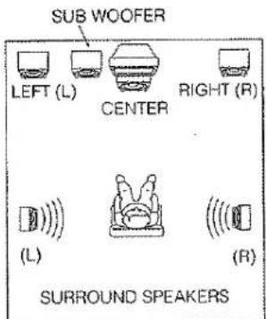
If possible, mount the surround speakers on the walls to the sides of the viewing area, 2-3 feet above seated viewers, firing straight across at each other.
SETUP 1/2 (SPEAKER SIZE)
SETUP 1/2 SPKR SETUP
SETUP UNLOCKED
FRONT CH : SMALL/THX
SURR CH : SMALL/THX
CENTER CH : SMALL/THX
SUBWOOFER : ON /THX
TO NEXT SETUP MENU
SETUP: Select "LOCK" with ◀ or ▶ button in order to lock the contents of the four CALIBRATION SET UP MENU.
Then, when you want to change the contents of these setup, select "UNLOCK".
SPKR setup (Speaker setup)
- This menu enters the information that the this product which type of speakers will be used for each channel
- If you use THX speaker systems which are approved by LUCASFILM LTD set FRONT CH SURR. CH, and CENTER CH to the SMALL position and then select SUBWOOFER =ON
- In turn, these settings will determine which speakers receive low frequency (bass) information.
For the purpose of establishing proper bass reproduction, use the LARGE settings if the speaker being used at any position is a traditional full-range loudspeaker that is capable of reproducing sound below 80 Hz.
Use the SMALL setting for smaller, frequency-limited satellite speakers that are not able to reproduce sounds below 80Hz.
Note that when "small" speakers are used it is advisable to install a separate subwoofer
- If the Surround speakers or Center speaker will not be used, set NONE for each speaker. The NONE setting will send the audio for the surround channels or Center channel to the front left/right speakers.
FRONT CH.: Select the type of front speakers with ◀ or ▶ button.
SURROUND CH.: Select the type of surround speakers with ◀ or ▶ button.
CENTER CH.: Select the type of center speaker with ◀ or ▶ button.
SUBWOOFER: Switch the subwoofer speaker ON or OFF with ◀ or ▶ button.
Notes:
The SUBWOOFER cannot be set to OFF when the front speakers are set to SMALL.
This speaker size setup is not effective when the SOURCE-DIRECT or 6CHANNEL-DIRECT mode is selected.
SETUP 2/2 (SPEAKER DISTANCE)
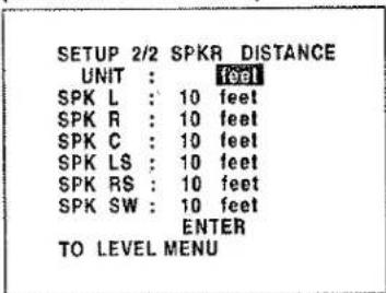
SPEAKER DISTANCE for Time Alignment
Use this parameter to specify the distance of the speaker's position from the listener.
The delay time is automatically set according to these distances.
UNITS: The units is able to select "FEET" or "METER" with ▶ or ▶ button. If you select "FEET" the setting parameter will change in 1 foot steps. If you select "METER" it will change in 0.3 meter steps.
SPK L= (Front L channel)
SPK R = (Front R channel)
SPK C = (Center channel)
SPK LS = (Surround L channel)
SPK RS = (Surround R channel)
SPK SW = (Subwoofer channel)
Input each speaker's distance with ◀ or ▶ button. Select speaker with ▲ or ▼ button. Input for each speaker's distance has been finished move to cursor to ENTER and push OK button.
Notes:
The maximum distance a speaker may be placed is 30 feet (9 meters) from the listening position. Placement beyond that distance is beyond the range of the automatic time delay feature. The delay feature does not function in the STEREO, SOURCE-DIRECT or 6 CHANNEL DIRECT modes.
LEVEL 1/2 (SPEAKER LEVEL BY TEST TONE)
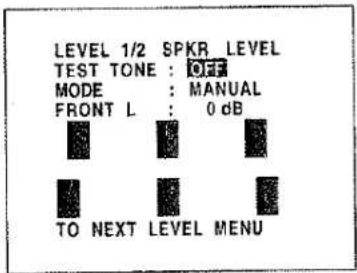
SPKR LEVEL
TEST TONE: Press the OK button, ON is indicated and the test tone starts from the front L-CH speaker. Press the OK button again, OFF is indicated and the output of the test tone will stop.
MODE: Select the mode for generating the test tone. If you select AUTO, test tone will be output in a circular pattern which is Left → Center → Right → Surround Right → Surround Left → Subwoofer → Left →... 3 seconds for each channel. If you select MANUAL, press the OK or CH+ button to select the test tone channels.
Channel: Adjust the level of test tone for each channel with the LVL+, LVL- or ▶/▶ buttons of the RC-18SR. The current volume level is shown at the center of the display.
Notes:
The setup level for each channel is memorized to reproduce the all surround mode. These levels are common for all surround modes, except 6CH-DIRECT mode.
In order to correctly set the output levels, use a hand-held Sound Pressure Level meter (SPL), set to C-Weighting and Slow averaging. A Radio Shack® SPL meter (catalogue number 330 - 2055) works well. Using the internal channel noise generators, set each channel so that you read 75 dB SPL from each channel."
LEVEL 2/2 (BASS PEAK LEVEL LIMIT)
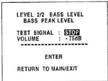
With Dolby Digital and DTS, not only the LFE (Low Frequency Effects), but also the bass of all channels can be heard from the Subwoofer or Large-speakers. This procedure prevents these speakers from becoming too loud and creating an unbalanced sound. Since the sound is output at a loud volume, perform this operation carefully.
TEST SIGNAL: Press the OK button, START is indicated and a Bass test tone is generated from the speaker, according to SPK size setup. But the sound is not heard because the Master volume is set to ≈ automatically. Press ▼ button to move the cursor to VOLUME control.
VOLUME: Adjust the bass test tone output level to where the bass sound begins to distort or maximum level with the VOL+, VOL- or ◀/▶ button. Press ▼ button to move the cursor to ENTER.
ENTER: Press the OK button, ENTER is blinking and the Bass test tone stops. The Bass Peak Limit Level for your system has been memorized
Notes:
Each time the subwoofer level is changed, perform the Bass Peak Level setup and correct the setting. The bass peak limiter is not effective in STEREO reproducing for analog input and 96kHz-PCM, or SOURCE-DIRECT and 6CHANNEL-DIRECT modes are selected. The selected value is displayed in the volume column before the test signal starts.
SURROUND MODE
SURROUND MODE
MODE : STEREO
NIGHT MODE : OFF
LFE LEVEL : 0dB
RETURN TO MAIN/EXIT
MODE: Select the surround mode with ◀ or ▶ button.
NIGHT MODE: Switch the NIGHT MODE ON or OFF with the ◀ or ▶ button. Selecting the Night Mode ON is effective in Dolby Digital only, and it compresses the dynamic range by up to 1/4 to 1/3. This softens loud passages such as sudden explosions, to help prevent disturbing others late at night.
LFE LEVEL: Select the output level of the LFE signal included in the Dolby Digital signal or the DTS signal. Select 0 dB, -10 dB or OFF with ◀ or ► button. The level is ordinarily set to 0 dB except DTS-Music mode. In the DTS-Music mode, default level is set to -10 dB.
REC COPY
REC COPY
VCR1 : SOURCE
TAPE : SOURCE
DIGITAL : SOURCE
RETURN TO MAIN/EXIT
VCR1 COPY
Select the visual source of the VCR1 output with ◀ or ▶ button for video and audio dubbing to the VCR1 deck.
The source is switched in the following sequence.
SOURCE → TV → LD → DVD → DSS/VCR2 → AUX → SOURCE → .... To determine each source, display the desired source and press the OK button or ▲ / ▼ button.
TAPE COPY
Select the audio source of the TAPE output with ◀ or ▶ button for audio dubbing to the tape deck.
The source is switched in the following sequence.
SOURCE → TUNER → CD → CD-R/MD → SOURCE → ....
To determine each source, display the desired source and press the
OK button or ▲/▼ button.
DIGITAL COPY
Select the digital source of the DIGITAL output with ◀ or ▶ button for digital dubbing to the CD-R recorder or MD deck.
The source is switched in the following sequence.
SOURCE → DIG.1 → DIG.2 → DIG.3 → DIG.4 → OFF → SOURCE →
To determine each source, display the desired source and press the
OK button or ▲ / ▼ button.
Notes:
VCR1 and TAPE1 outputs can only send a signal from an analog source connected to the SR-19. If you select a source which is only connected to a digital input, no signal will be available to output to a VCR1 or TAPE1 deck from the analog output. If you expect to do dubbing from digital source equipment to analog equipment, then you should connect the digital equipment's analog outputs into the SR-19's analog inputs in addition to making the digital connections. Conversely, a digital source may only be dubbed using the DIGITAL output, which must in turn be connected to a digital input of a digital recording device such as the DR-700 or DR-17 CD recorder. Remember-you can only dub analog to analog or digital to digital.
MULTI ROOM SELECT
MULTI ROOM SELECT
| MULTI ROOM : OFF |
| VISUAL : TV |
| AUDIO : TUNER |
| VOLUME : VARIABLE |
| LEVEL : -90dB |
RETURN TO MAIN/EXIT
MULTI ROOM: To switch on the Multi-room output, move " " with ◀ or ▶ button.
VISUAL: Select the visual source of the Multi-room output with ◀ or ▶ button.
AUDIO: Select the audio source of the Multi-room output with ◀ or ▶ button.
VOLUME: Select whether the Multi-room output level is to be made variable or fixed with ◀ or ▶ button.
LEVEL: Adjust the Multi-room output level with ◀ or ▶ button.
Notes:
As described in the notes above, multi-room sources must also be analog. You cannot transmit a digital signal using the multi-room function. If "VOLUME" is set to "FIXED", the multi-room output level cannot be adjusted.
STATION NAME INPUT
STATION NAME INPUT
PRESET NUMBER : 1 FM 87.50 MHz AUTO
NAME : CHARACTERS
ABCDEFGHIJKLMNOPQRSTUVWXYZ1234567890-+/
RETURN TO MAIN/EXIT
Use this menu to add names to your preset stations.
-
Enter the preset number you wish to name using the PRESET button ⑱ and then scrolling with the GYRO TUNING knob ⑲ until you reach the desired preset station.
-
The station will be displayed (including the name if you have already assigned one). In either case, the cursor will blink at the first letter of the station name.
-
Press the OK button or use the ◀/▶ buttons on the remote to position the cursor where you want it.
-
Use the ▲/▼ buttons to select the desired character
-
Place the cursor over the character you wish to enter using the ▲/▼/◀/▶ buttons. Press the OK button when you are at the character you want.
-
Repeat steps 3 to 5 to enter additional characters. You can enter up to 8 characters in total.
BASIC OPERATION
LISTENING TO THE TUNER
MANUAL TUNING
-
To select the tuner as the source, turn the INPUT SELECTOR knob ② on the front panel or press the TUNER button ⑨ on the remote.
-
Press the BAND button ⑥ on the SR-19 or BAND button D4 on page 1 at TUNER MODE on the remote to select the desired frequency band if required.
-
Press the AUTO TUNING button ⑰ on the SR-19 to display the frequency.
-
Turn the GYRO TUNING knob ② on SR-19 or press ◀ or ▶ button on the remote.
-
If FM is selected, press the FM MODE button ⑦ on the front panel or the MODE button D5 on the remote to select the desired audio mode.
AUTO TUNING (USING THE SR-19)
Light up the "AUTO TUN" indicator by pressing the AUTO TUNING button ⑰ and turn the GYRO TUNING knob ⑫.
AUTO TUNING (USING THE REMOTE CONTROL UNIT)
◀ or ▶ button is pressed for more than 1 second to start Auto tuning function.
(FM) MODE Button Operation
When "AUTO" indicator is on in the display, FM stations which broadcast in stereo will be received in stereo and the "STEREO" indicator lights.
When "AUTO" indicator is off, all the FM stations will be received in monaural regardless of whether or not they are broadcasting in stereo.
PRESET TUNING
With this unit you can preset up to 50 FM/AM stations in any order. For each station, you can memorize the frequency and reception mode if desired.
1-a. Manual Presetting (Using the SR-19)
- Refer to the "MANUAL TUNING" or "AUTO TUNING" section above to tune in a desired station.
- Press the MEMO button ⑧. "MEMO" indicator starts blinking on the display. While "MEMO" is still blinking (approx. 5 seconds), select the preset number by turning the GYRO TUNING knob ②, then press the MEMO button again.
- When a number has been properly input, "MEMO" indicator stops blinking and goes out. The station is now stored in the specified preset memory location.
1-b. Manual Presetting (Using the remote unit)
- Tune in a desired station.
- Press the MEMO button 13.
- Enter the desired preset number with ten keypad 12.
* When entering a single digit number (2, for example), either input "02" or just input "2" and wait for a few seconds.
* If a number other than 1-50 is entered by mistake, that number flashes in the display to indicate that it is invalid and the display returns to the original frequency display.
2. Auto Presetting
This function automatically scans the AM and FM band and enters all stations with proper signal strength into the memory.
This function is available only for SR-19.
- Select the FM band with the BAND button ⑥.
- Tune in the lowest receivable frequency.
- While pressing the MEMO button ⑧, turn the GYRO TUNING knob ② to up. Auto memory starts at this point.
-
"MEMO" will blink on the display.
-
Each time the tuner finds a station, the scanning will pause and the station will be played for five seconds. During this time, the following operations are possible:
1) The band can be changed using the BAND button ⑥. 2) The mode can be changed using the FM MODE button ⑦. - If no button is pressed during this period, the current frequency is preset in location CH-2. If you wish to skip the current station, turn the GYRO TUNING knob ② during this period, the current frequency is skipped and auto presetting continues.
- Operation stops automatically when all 50 preset memory positions are filled or when auto scanning attains the highest end of all bands. To stop the auto preset function at anytime, press the CL (CLEAR) button ⑨.
3. Recalling a Preset Station
- Press the PRESET button ⑱ to change the display to preset.
- Select the desired preset station by turning GYRO TUNING knob ② on the front panel or press ◀◀ or ▶▶1 button ⑮ on the remote.
Note;
Direct selection method using the ten keypad on the remote, select the desired preset station by entering one or two digits using the ten keypad 12. To return to the Manual Tuning mode, press the AUTO TUNING button 17.
4. Preset Scan Tuning (Using the remote control unit)
- Press the SCAN (preset scan) button D8 on the remote. "P-SCAN" indicator blinks in the display. (The preset station with the smallest preset number is recalled first. If no stations have been preset, CH "00" blinks in the display and the unit returns to the previous mode.)
- Preset stations are recalled in sequence (CH-1 > CH-2, etc.) for 5 seconds each. Preset numbers that do not contain stations are skipped.
- You can fast forward the preset stations by pressing the button continuously. When the desired preset station is received, cancel the preset scan operation by pressing the button on the SCAN button D8 or CL (CLEAR) button ⑨.
5. Clearing Preset Stations
You can remove preset stations from memory using the following procedure.
- Recall the preset number to be cleared with the method described in "Recalling" a preset station.
- Press the MEMO button ⑧ on the front panel or M (MEMO) button ⑬ on the remote unit, "MEMO" blinks in the display for 5 seconds. While "MEMO" is still blinking, press the CL (CLEAR) button ⑨ on the front panel or C (CLEAR) button ⑭ on the remote unit. "CLEAR" appears on the display to indicate that the specified preset number has been cleared.
STATION NAME PRESET
The station name preset function allows the name of each preset channel to be entered using alphanumeric characters. The Station Name button is valid only in the tuner mode. Before station name preset operation, store stations with the preset memory operation.
- Press the MEMO button ⑧ on the front panel or M (MEMO) button ⑬ on the remote for more than 3 seconds.
- The left most column of the station name indicator flashes, indicating the character entry ready status.
[Operation (Using the SR-19)]
- When the GYRO TUNING knob ② is turned, alphabetic and numeric characters will be displayed in the following order:
$$ \begin{array}{c}\mathbf {A} \rightarrow \mathbf {B} \rightarrow \mathbf {C} \dots \mathbf {Z} \rightarrow 1 \rightarrow 2 \rightarrow 3 \dots , 0 \rightarrow - \rightarrow + \rightarrow / \rightarrow (\text { Blank }) \rightarrow \mathbf {A}\\mathbf {U P} \rightarrow\\leftarrow \text { DOWN }\end{array} $$
- After selecting the first character to be entered, press the MEMO button ⑧. The entry in this column is fixed and the next column starts to flash. Fill the next column and press the MEMO button ⑧ for more than 1 second to confirm the entry.
[Operation (Using the remote unit)]
First, press the TUNER button on the remote control unit. (This operation is not necessary if the remote control unit has already been operated in the TUNER mode.)
- Enter the character using the ten keypad 12. For example, to enter "A":
1) Press the "1" button. "A" appears on the display column. 2) Every time the 1 button is pressed, the displayed character changes in the order: A → B → C → 1 → A...
Pressing buttons other than the "1" button cause different characters to be displayed in a similar way, so that other alphanumeric characters can be entered. To enter a blank or space, press the "9" button. - When the desired character is displayed, press the M (MEMO) button 13 to confirm the entry in this column and move to the next column. After having filled all of the 8 columns, press the M (MEMO) button 13, for more than 1 second to confirm the entry.
PLAYBACK OPERATION
NORMAL PLAYBACK
- Press the POWER ON button on the remote.
- Turn the INPUT SELECTOR ② on the front panel or press the FUNCTION button ③ on the remote unit to select an input source.
- Press the Surround mode buttons ③ on the front panel or Surround mode buttons D1 to D8 on page 1 in the AMP MODE on the remote unit to select the desired surround mode.
- Adjust the volume level using the VOLUME knob ⑩ on the front panel or press the VOL + / - button ⑪ on the remote. If necessary, adjust the tone using the BASS and TREBLE buttons D1 to D4 on page 3 in the AMP MODE on the remote unit.
Note:
In case of remote control operation, press one of the function buttons twice within 2 seconds to select the function.
LISTENING TO A DIFFERENT AUDIO SOURCE WHILE WATCHING A VIDEO SOURCE (Using the remote control unit)
- Select one of the following video sources TV, LD, DVD, VCR1, DSS/VCR2 or AUX.
- Next, select one of the following audio sources FM, AM, CD, TAPE, or CDR/MD.
OTHER FUNCTIONS
MULTI ROOM SELECTOR
The Multi Room Selector is a function which allows you to listen to the same or a different source in a room other than the room in which the SR-19 is located. To use this function, a multi room remote unit and remote control signal receiver available from your Marantz dealer are necessary. The operations possible with the multi room function are explained briefly below. For details, refer to the instruction manual supplied with the multi room remote control unit and receiver.
MULTI ROOM SELECTOR OPERATION
- Press the MULTI button ⑮. The unit enters multi room mode and the display indicates "SEL SOURCE" and flashes the "MULTI" indicator for approx. 10 seconds. In this time, you can select the input source by turning the INPUT SELECTOR knob ②.
- Then, the display indicates "MULTI VOL" "VOLUME xx dB" for approx. 5 seconds. At this time, you can set the volume level of the multi room.
MULTI ROOM SELECTOR OPERATION (USING THE MULTI ROOM REMOTE CONTROL UNIT)
- Press the MULTI button, the POWER ON button, or select the desired source on multi room remote control unit from the MULTI ROOM. Any of these operations will put the SR-19 into multi room mode and "MULTI" will light in the display.
- Press the VOL.UP or VOL.DOWN button on the multi room remote control unit to set the desired sound volume.
- In multi room mode, the multi room remote control unit can be used in the multi room to operate the following functions. You can select a tuner preset channel and tuning up or down, and direct selection. And you can control the CD player LD player, DVD player and tape deck connected to the SR-19.
Caution:
Multi room mode can be selected when the SR-19 POWER switch ① is turned on.
If the main room is active (not standby mode), you cannot select the frequency band except the band of the main room. For example; if the FM band is selected in the main room, you cannot select the AM band in the multi room.
The operating procedure for this is the same as the Multi-room operations using the remote unit.
DIALOGUE NORMALIZATION MESSAGE
Dialogue Normalization (Dial Norm) is a feature of Dolby Digital. When playing back software which has been encoded in Dolby Digital, sometimes you may see a brief message in the front panel display which will read "Dial Norm X dB" (X being a numeric value). Dialogue Normalization serves to let you know if the source material has been recorded at a higher or lower level than usual. For example, if you see the following message: "Dial Norm + 4 dB" in the front panel display, to keep the overall output level constant just turn down the volume control by 4 dB. In other words, the source material that you are listening to has been recorded 4 dB louder than usual. If you do not see a message or see "Dial Norm 0 dB" in the front panel display, then no adjustment of the volume control is necessary.
TV AUTO ON/OFF FUNCTION
This function allows the component connected to the TV IN jack to control the power (ON/OFF) to the SR-19.
AUTO POWER ON
- Be sure TV auto mode is on. (Refer page 9: System Setup 2/2)
- Connect your TV TUNER (etc) to the TV IN terminal. Be sure to connect the video input.
- Turn OFF the power to the TV TUNER and the SR-19.
- Turn ON the TV TUNER and tune in a receivable station.
- When the station is received, the SR-19 turns ON and TV is selected automatically.
AUTO POWER OFF
- In the above situation, turn the TV TUNER OFF or select a channel that does not contain any broadcast.
- The SR-19 switches to STANDBY after approx. 5 minutes.
Note:
AUTO POWER OFF is canceled if the INPUT SELECTOR knob ②1 is set to a source other than TV. The function reactivates when TV is selected again.
Caution:
Some TV broadcasts may cause the TV AUTO FUNCTION to be turned ON. To set this function ON/OFF, refer to the SETUP MENU.
SETTING THE SLEEP TIMER (ONLY REMOTE CONTROL UNIT)
Set the sleep timer while the power is turned on.
- Turn the power ON and press the SLEEP button D5 on page 4 at AMP mode.
"SLEEP" blinks on the display. - Press the SLEEP button D5 the number of times to set the desired sleep time. Each press of the SLEEP button D5 changes the display in the following order:

flowchart
graph TD
    A["10"] --> B["20"]
    B --> C["30"]
    C --> D["40"]
    D --> E["50"]
    E --> F["60"]
    F --> G["70"]
    G --> H["80"]
    H --> I["90"]
    I --> J["OFF"]
    J --> A
"SLEEP" stops blinking and lights steadily.
* While the sleep timer is activated, the remaining time can be displayed for approx. 2 seconds by pressing the SLEEP button.
* To cancel the sleep timer, press the SLEEP button D5 and then press the C (CLEAR) button 14.
REMOTE CONTROL UNIT RC-18SR
- The remote control unit provided with the SR-19 is a "learning"-type, programmable unit capable of controlling almost any component in your system, as well as the Marantz D-BUS components (RC-5). The components to be controlled can be selected with 11 function buttons.
OPERATION
The provided remote control unit (RC-18SR) is a system remote controller. The POWER button [4], 10-key numeric buttons [12] and control buttons [15] are used in common across different input source components.
The input source system controlled with the RC-18SR changes when one of the input selector buttons 9 is pressed.
•Example: To select the LD player as the input source and play an LD on it
Press the LD button twice within 2 seconds.
The input function of the SR-19 is switched to LD and the RC-18SR is set for control of the LD player. Press the PLAY ▶ button 15 to play an LD.
FUNCTION AND OPERATION
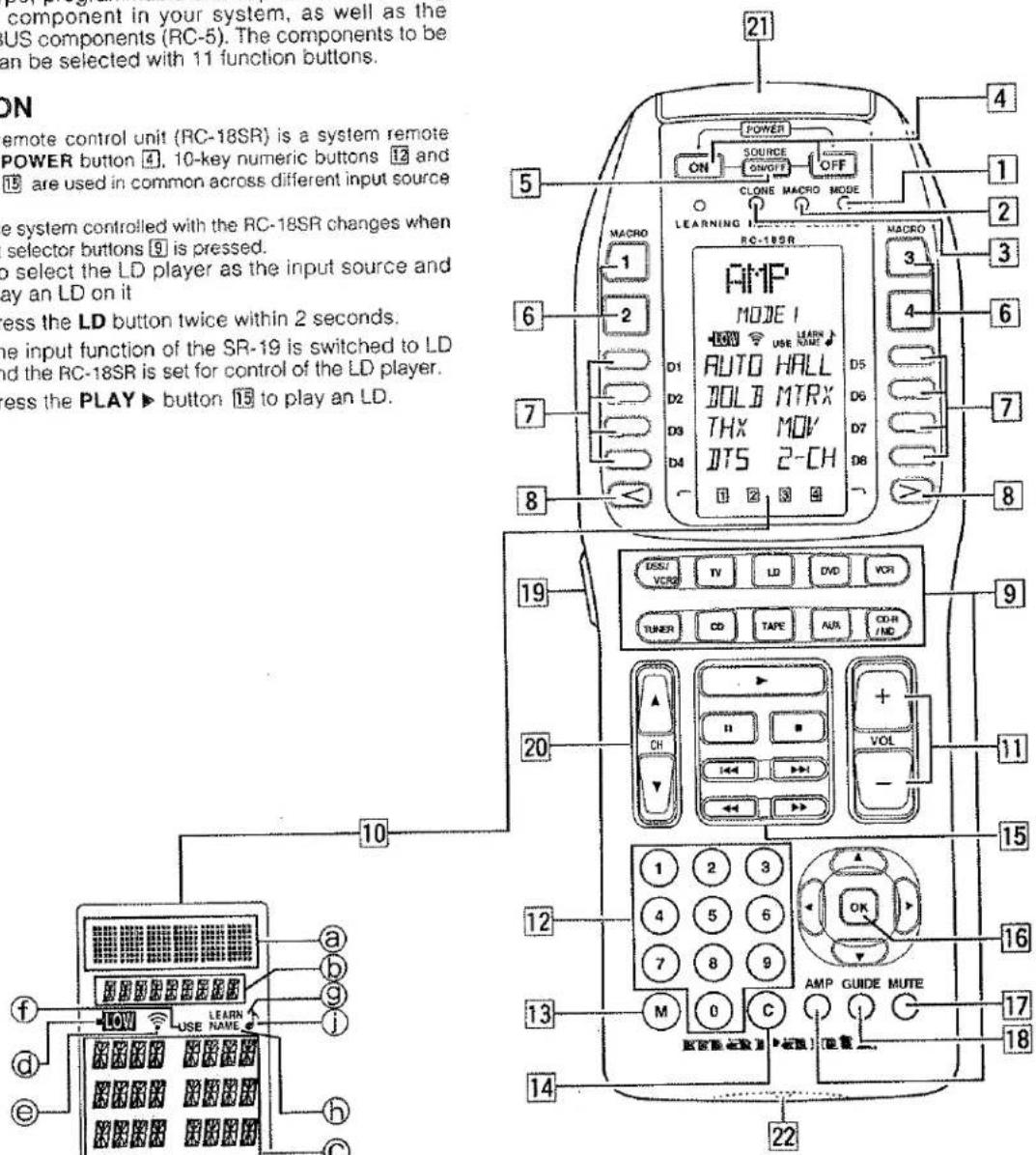
1 MODE (operating mode)
This button is used to change from normal operation to the learning mode, and is used when "learning" commands from other brands of A/V components. Each time this button is pressed (using a small pointed instrument, such as the tip of a paper clip) the mode changes as follows: LEARN → USE → NAME. As the mode changes, the LCD display will show which mode is currently selected.
2 MACRO (for multiple step macro functions)
This button is used to memorize a series of functions. When this button is pressed, the RC-18SR changes to macro programming mode, and is ready to learn a sequence of remote control commands.
3 CLONE
The RC-18SR has the ability to "replicate" itself, downloading all of its internal pre-programmed and user-programmed commands to another RC-18SR or RC2000MKII. This button is used when you wish to "teach" another RC-18SR or RC2000MKII all of the customized commands you've already programmed in this RC-18SR.
4 POWER ON and OFF
These two buttons are used to turn the main component's (amplifier or receiver) AC power on and off. We provide both ON and OFF commands so that your A/V system is remote compatible with external infrared controllers, such as in-wall key pads, etc.
5 SOURCE ON/OFF
This button is used to turn the AC power on and off to any of your A/V source components that have their own remote control turn-on and turn-off commands, such as TV, laser disc player, VCR, etc.
6 MACRO 1-4
Each of these 4 buttons can be programmed with a "string" of commands, called a macro, to initiate a sequence of remote codes to achieve a particular result. For example, a macro button could be programmed to turn on the main system power, then turn on a particular source component (such as a laser disc player), then turn on the TV set, set the TV to AUX video input, and then adjust the surround processor to the home theater surround decoding mode, then activate the laser disc player's PLAY function. This means that by pressing one macro button, you can achieve the same result as pushing up to 20 buttons in sequence.
7 DIRECT
With today's high performance A/V systems, it is not unusual for each component in your system to have dozens of specialized command functions. If we were to duplicate all of those commands for each component onto the RC-18SR key pad, we could easily exceed 300 buttons for an entire home theater system, which would result in either a huge key pad, or buttons of infinitesimal size. The DIRECT command buttons (4 on each side of the LCD display, 8 total) work with the PAGE buttons (4 pages for each source component) to provide up to 32 dedicated specialized functions for each of the 11 function input selectors. Each DIRECT function may also be provided with an alphanumeric function indicator visible in the LCD display. You may even change the displayed name of each function to another name, if you wish.
8 PAGE
Used to select any 1 of the 4 pages of 8 functions for each DIRECT button, as explained above.
9 FUNCTION
Press one of these buttons once or twice to select a particular source component. For example, to set the amplifier or receiver to the laser disc input, press the LD button twice within 2 seconds. Along with the source selection, special functions may become available (the DIRECT keys), as well as activating the transport function keys, so that you can now directly operate the laser disc player from the RC-18SR. If you wish, you may even re-program the status indicators in the LCD window to reflect your own particular function name whenever that source (function) button is selected.
Here are the button names and their functions:
| LD | : Laser disc player |
| TV | : Television |
| VCR1 | : Video cassette recorder |
| DSS/VCR2 | : Digital satellite decoder or second video cassette recorder |
| AUX | : Can be used for an auxiliary source component |
| TUNER | : AM/FM tuner, or AM/FM tuner section of a receiver |
| CD | : Compact disc player or changer |
| TAPE | : Audio tape deck, or digital audio recorder |
| AMP | : Amplifier or receiver control functions |
| DVD | : Digital video disc player |
| CD-R/MD | : CD-Recorder or mini disc player |
Note:
Press a function selector button only once to select the LD player, etc. Remember, when you press a function selector button only once, the RC-18SR will not send out a remote control code to instruct the amplifier or receiver to change to that corresponding input, but the RC-18SR keypad and DIRECT function commands will provide the selected component's specialized remote control codes. Press a function selector button twice within 2 seconds to change the function of the amplifier or receiver.
For example, if you press the LD function button twice within 2 seconds, the amplifier or receiver's input will immediately be switched to the laser disc input, and the keypad and DIRECT function commands for laser disc operation will be activated. Press the CD function button only once, the amplifier or receiver's input will not switch to the CD input, however the RC-18SR keypad and DIRECT function commands for compact disc operation will be activated.
We have provided 11 popular function command selector buttons, based upon the typical input selections available with most quality A/V amplifiers (or receivers) including popular Marantz models.
The function button DSS/VCR2 is a little different from the others, in that when you press this button, the RC-18SR will send out a command to the amplifier or receiver to switch to the DSS input, and then the RC-18SR keypad and DIRECT function commands will be configured for DSS (digital satellite system) control. We have included DSS commands within the RC-18SR's pre-programmed memory for RCA brand DSS equipment. If you have another brand of DSS, you can "teach" the RC-18SR with the remote control codes of your equipment.
10 LCD window
The LCD window provides a wealth of information, including function selection name, DIRECT function names, learning and programming steps, as well as useful indicators for battery status, and other helpful indicators. The LCD window features back-lighting, making it easy to view when the room light is very low.
11 Volume up (+) and down (-)
Used to raise and lower the main system volume level. Note that these buttons are clearly the largest size, and are conveniently located and contoured for easy operation, even in low lighting.
12 Ten keypad
Like a telephone key pad, the ten number buttons (0-9) are used to enter numeric digits. They are useful for finding a specific track on a CD, or to tune a pre-set radio station, etc. The "0" button performs the same operation as the "CLEAR" button on the SR-19 main unit.
13 MEMO
This button is used to program your CD player's track memory, or to enter a VCR recording program, and can be used to provide the MEMO function included with other components in your system.
14 CLEAR
This button is used to cancel certain memory or programming operations. It operates differently from the "CLEAR" button on the SR-19 main unit.
15 Transport control functions
These buttons provide transport commands for your source components, such as laser disc player, CD player, VCR, audio tape deck, etc., and are dependent on the function source selected. For example, when the RC-18SR is set to LD (laser disc) mode, the transport keys will operate the laser disc player's PLAY, STOP, PAUSE, FAST FORWARD, FAST REVERSE, NEXT and PREVIOUS track functions. Change the RC-18SR function selector to VCR, and these keys will then operate the VCR's transport command functions, etc.
16 CURSOR buttons
Some components feature menus that are navigated with up, down, left and right direction commands. The cursor buttons can be used to navigate within on-screen menus, for components such as amplifier or receiver, TV set, DSS/satellite tuner, etc. These buttons are also used for certain RC-18SR programming functions.
17 MUTE
For those components (such as amplifier or receiver, TV, etc.) with a mute function, this button can be used to mute the sound temporarily.
18 GUIDE
This button is intended for owners of DSS (digital satellite system) or similar equipment, to activate the on-screen programming guide, used when changing channels, etc.
19 LIGHTING
Press this button to activate the back-lit LCD screen and back-lit keys independently SETUP mode. A quick touch is all that is necessary. The back-lighting will remain on for 3 seconds. If you wish, you can even re-program the RC-18SR to shorten or lengthen the amount of time the back-lighting is activated when this button is pressed.
20 Channel up(▲), down(▼)
Press this button to change the tuner, TV, DSS or VCR preset channels to upward or downward.
21 Transmitter window
Infrared signals will eminate from behind this window. Simply aim the RC-18SR towards the component(s) you wish to control. You may find that the RC-18SR works fine when placed on a coffee table pointing towards your A/V system components.
22 Receiving window
Used when learning commands from other remotes, this window is placed at the bottom of the RC-18SR, so that the two remotes are vertically oriented for easy transfer of remote control information. Later in this guide we will show you which of the RC-18SR buttons can be "taught" new commands from other components.
LIQUID CRYSTAL DISPLAY (LCD) WINDOW
Within this display, all operating messages (function name, mode names, etc.) are shown. When a particular button is pressed (such as a transport command, like PLAY), its status will be shown in the display for 1 minute. The display will continue to show the source function selected continuously, however.
① Function indication:
The selected source function is displayed, such as LD, TV, etc., up to 6 characters maximum.
⑥ Status indication:
The selected status of the present page, or other items, is displayed, up to 9 characters maximum.
© Direct commands:
8 DIRECT commands are available in 1 page, up to 4 characters maximum.
⑭ Battery indicator:
When the batteries are running low, this indicator will become visible. At this point, it will not be possible to learn any new remote codes, but normal remote control operation is still provided (including the use of any previously learned codes). At this point, you should consider changing the batteries soon. As time goes on, and the battery power diminishes further, this indicator will begin blinking. At this point, no remote commands will be transmitted. This is your signal to replace the batteries with fresh ones as soon as possible. Eventually, if you ignore the blinking battery indicator and do not install fresh batteries, then the batteries may eventually be totally exhausted, and the LCD display window will be completely blank. However, any previously learned commands and macros will not be erased from the microprocessor's memory.
The RC-18SR is supplied with a full set of RC-5 remote control codes in permanent (non-volatile) memory. Even if the batteries are fully exhausted, the RC-5 codes (used for Marantz A/V components) and learned codes will never disappear.
We recommend that you use a quality brand of alkaline batteries, for best results and longest life. Newly available lithium "AA" batteries can even provide longer life than alkaline batteries, and are also recommended.
© Transmit indicator:
When a button is pressed, this indicator shows that an infrared code is being transmitted.
④ USE indicator:
For normal operation, the USE indicator should be visible.
⑨ LEARN indicator:
Visible when the RC-18SR is set to LEARN mode.
⑥ NAME indicator:
Visible when the RC-18SR is in the learning mode, and function naming is being changed.
① PAGE or MACRO indicator:
This indicator usually functions in association with a PAGE button 8, but also functions as the MACRO indicator when a MACRO button 6 is pressed.
① indicator:
Visible when the RC-18SR is set to the beep function.
Installing the batteries:
The battery compartment is located on the rear panel. Please use only alkaline or lithium batteries, "AA" size. The RC-18SR requires four AA batteries. There are markings in the battery compartment to show you the proper battery orientation. If after installing the batteries, you cannot see any indication in the LCD window when a button is pressed, re-check to ensure that the batteries are properly positioned in the compartment.
RC-18SR BASIC OPERATION
USE Mode:
As supplied from the factory, the RC-18SR is already permanently programmed with many pre-set commands common to Marantz and Philips equipment, as well as other brands of components that utilize the Philips RC-5 remote control language.
- If the RC-18SR is in another mode (LEARN, etc.), press the operation mode button ① with the tip of a paper clip, until the USE indication appears.
- Press one of the function buttons ⑨, to change to another component's commands such as LD (refer to Figure 1).
Figure 1
| LO | |
| MODE | |
| 50-A | RPTA |
| 50-B | RPTB |
| DISP | CP/F |
| ANS | EXIT |
| 0 | 2 3 4 |
- "LD" will be indicated within the LCD window, and the function codes will be set to operate the laser disc player. Press the function button again within 2 seconds and the amplifier or receiver's input changes to laser disc.
- Now you can operate the laser disc player. When a button is pressed, the symbol indicates that a remote code is being transmitted. Note that for a particular source component, not every button may have a command programmed for it. In that case, nothing would be indicated.
- Using the DIRECT buttons D-1 through D-8 and PAGES 1 through 4, up to 32 different specialized commands are available for each FUNCTION, up to a total of 352 specialized commands (32 direct commands times 11 functions). Note that for any particular function selector, not all 32 direct commands may be provided and/or named as supplied from the factory.
- For example, the RC-18SR is supplied from the factory with 3 pages of DIRECT commands for the LD (laser disc) function. To change pages, press the page direction ◀ or ▶ buttons [8]:
Page 1: MODE: Side A/B laser disc playback functions
Page 2:L D: Specialized laser disc functions
Page 3: R E C: Recording from laser disc to VCR functions
At this point, you may wish to put this guide aside temporarily, and begin using the RC-18SR with your A/V system. If you already have any Marantz components, or Philips and/or other brands of components that use the RC-5 remote control language, you can begin controlling those components with the RC-18SR right away. Take some time to become comfortable with the operation of the RC-18SR. We think that its intuitive key pad layout and easy to read LCD window will permit you to quickly become familiar with its operation.
If you do not have any Marantz or other brands of components that use the Philips RC-5 remote control language, then you may wish to proceed to the next section, which will describe the steps necessary to "teach" your RC-18SR remote codes from other components you may have in your system.
LEARN mode:
The RC-18SR has the ability to learn remote codes for just about any component in your A/V system. If the original component was supplied with an infrared remote control, its commands can be learned by the RC-18SR. If you have another brand of laser disc player, for example, you can program the RC-18SR with its codes. For example, we'll show you how to "teach" the RC-18SR commands from another brand of laser disc player.
- Using a sharp point (such as the tip of a paper clip), press the operation MODE button [1]. Each time you press the button, the mode within the LCD display, the LEARN indicator will begin blinking.
-
Place the laser disc player's supplied infrared remote controller so that its transmitter window (usually at the top) is facing the receiving infrared sensor window 23 of the RC-18SR (at the bottom), about 5 cm (2 inches) apart.
-
Press the LD function button on the RC-18SR.
-
Press the play button 15 on the RC-18SR.
-
Press and hold the corresponding PLAY button on the laser disc player's remote transmitter until the "OK" indicator appears in the RC-18SR LCD window (see Figure 2) or the beep sounds ermit (if the beep sound function is set).
Figure 2
| LD | |
| 0# | |
| SD-A | RPTA |
| SD-B | RPTB |
| DISP | CP/F |
| AMS | EDIT |
| 回234 | |
If the "AGAIN" indicator appears in the RC-18SR LCD window, it means that for some reason the command was not properly learned. Repeat steps 3, 4 and 5 above.
In the unlikely event that an infrared command cannot be learned by the RC-18SR, "NG" (no good) will appear in the LCD window, meaning that the command is not "learnable". The RC-18SR has been tested for compatibility with a very wide range of infrared remote control frequencies and data word lengths, but in some very rare instances, it may not be possible to learn a particular remote control command.
Continue to "teach" the RC-18SR the rest of the source transmitter's transport function commands, such as STOP, PAUSE, NEXT, PREVIOUS, FAST FORWARD and REWIND, by repeating steps 3, 4 and 5 above.
- Proceed to learn the numeric "10 keys" from the source transmitter to the RC-18SR's '10 key numeric pad 12 by repeating steps 3, 4 and 5 above.
- For each additional function, such as TV, VCR, etc., repeat steps 3, 4 and 5 above. During the LEARN operation, if any button is not pressed within 1 minute, the RC-18SR will revert back to the previous operating mode.
- To make a function button learn a code, switch the input function then press the button again.
- After memorizing all desired remote codes, press the operation mode button ① with the tip of a paper clip, and select the USE mode. The LCD display window will continue to display the USE indicator, and all of the newly memorized codes will be available (see Figure 3).
Figure 3
| LD | |
| NOTE | |
| SD-A | RPTA |
| SD-B | RPTB |
| DISP | CP/F |
| PMS | EDIT |
| @ : : : | |
For any button for which a new code was not learned, the factory programmed RC-5 code will still transmit as usual.
Note:
POWER ON/OFF 4 code can be learned regardless of the function button selection:
Programming the DIRECT mode buttons 7:
The following example will show how to memorize the SIDE-A function command of another brand of laser disc player into the D1 direct button.
- Using a sharp point (such as the tip of a paper clip), press the operation MODE button ① to switch the RC-18SR to LEARN mode.
- Place the laser disc player's supplied infrared remote controller so that its transmitter window is facing the receiving infrared sensor window of the RC-18SR about 5 cm (2 inches) apart.
- Press the LD function button ⑨ on the RC-18SR.
-
Using the direct function page keys ◀ and ▶ 8, set the direct function to Page 1. Press the D-1 button 7 on the RC-18SR.
-
Press and hold the corresponding SIDE-A button on the laser disc player's remote transmitter until the head of name blinks in the RC-18SR LCD window or beep sounds emit. The RC-18SR changes to the RENAME mode automatically as the next step. A function name of the DIRECT function button blinks, you can rename this blinking function name. You input the desired letter or number with the ten keypad. (See the table in step 3 of the next procedure for reference.) If you need not rename, press the OK button or the other buttons except the ten keypad.
-
Now, proceed to program the other commands from the laser disc player's remote transmitter to the other DIRECT function buttons (D2-D8). When you have "taught" all 8 direct functions for Page 1, press the page direction key ▶ 8 to go to Page 2, and you can program more direct function keys.
-
After memorizing all codes to all DIRECT function buttons, press the operation MODE button [1] with the tip of a paper clip and return the RC-18SR to the USE mode. Now, the newly memorized codes are usable from the RC-18SR.
If you wish, you can re-write the names for each function name, status name, and the direct function command names as follows:
For our example, you can change the LCD display window indication from "LD" to "LV-520" (which is the model number for a Marantz laser disc player). Remember, you can re-name a function selector button with a new name of up to six characters of letters and numbers in any combination.
- Using the tip of a paper clip, press the operation MODE button ① until the NAME indicator appears and begins to blink in the LCD window.
- Choose a button that you wish to re-name, in this case, press the "LD" function button [9]. In the LCD window, the first character of the six function character display indicators starts blinking "A", which is the first letter of the alphabet if you press "1" button twice.
- Choose the desired letter or number by pressing the 10 keypad buttons [12]. Each 10 keypad button has 4 characters attached to it as follows:
| 10 keypad button | Press, press again, press again, etc. |
| 1 | 1 A B C 1 ...... |
| 2 | 2 D E F 2 ...... |
| 3 | 3 G H I 3 ...... |
| 4 | 4 J K L 4 ...... |
| 5 | 5 M N O 5 ...... |
| 6 | 6 P Q R 6 ...... |
| 7 | 7 S T U 7 ...... |
| 8 | 8 V W X 8 ...... |
| 9 | 9 Y Z / 9 ...... |
| 0 | 0 + - SPACE , ' 0 ...... |
So, in the above example, by pressing the 10 keypad number 4 four times, you get the letter "L" to appear in the display (see Figure 4).
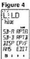
-
You use the cursor buttons◀ and ▶ 16 to move to the next character in the display. By pressing the right cursor button ▶, the letter "L" is confirmed in the first character space in the LCD window and the next character position begins blinking. If you wish to erase a previously memorized character, position the cursor over the character and put the SPACE character in its place (the SPACE character is ten keypad number 0 pressed four times, from the above character chart).
-
Continuing along, re-write the remaining letters "V", "-", "5", "2", and "0". By pressing the cursor keys ◀ and ▶, each character is confirmed in place. When you go to other DIRECT function pages by using the page function keys [8], characters in the previous page are also confirmed in place.
The name re-writing operation must be done on a function by function basis, that is, re-write the names for all of the LD direct functions, then switch to another function such as VCR, and begin the re-writing process anew to re-name the VCR direct function commands. After completing all re-writing of any of the names, press the OK button within the cursor keys 16.
How to re-write the STATUS name:
Using the same steps as outlined above, you can re-write the 9 character status name. During step 5 above, by pressing the up and down cursor keys 16 the left side of the status indicator begins blinking, and you can change its display according to the same method outlined above, using the 10 keypad character generator. Remember, to confirm each character change, use the cursor keys ◀ and ▶. As above, when you change the direct function page by pressing the page direction keys 8, this will confirm the re-written characters in place as well for the page you just finished re-naming. You have up to 9 letters, numbers or other characters available for each status name.
How to re-write the DIRECT function button names:
You can change the name for each of the 8 direct function buttons by using the steps described above to change main function name and status name. Remember, each main function has 8 direct function buttons on each of the 4 pages, so you have up to 32 direct functions that can be re-named, if you wish, for each of the 11 main function selection buttons [9]. You have up to 4 characters available for each direct function button name.
After completing all re-writing of any of the names, press the OK button within the cursor keys 16, or switch to another function button (such as CD). If, during re-naming, a button has not been pressed for 1 minute, the RC-18SR will revert to the prior operating mode (USE) automatically.
If re-writing of all of the desired direct mode functions has been completed, use the tip of a paper clip to press the operation MODE button [1], and select the "USE" mode. Now, all of the re-written names are available for use.
How to clear (erase) the memorized codes
(and any re-written names):
The RC-18SR has a high capacity RAM, which ordinarily will allow the learning of several hundred remote codes (and their associated new names, if desired). However, due to the fact that some remote codes occupy more memory space than others, it is possible that the available RAM fills up completely, and the "FULL" indicator appears in the LCD window. In this case, it will not be possible to learn any new remote codes without first deleting some or all of the previously learned remote codes and/or re-written names. There are 4 ways to erase learned remote codes from memory:
- Erasing by button(s)
• Erasing by DIRECT button(s) - Erasing by function(s)
• Erasing all memory contents (complete erasure)
•• Note that the factory-programmed RC-5 codes are not stored in RAM, and are therefore not erasable.
For any of these memory erasure options, you must first set the RC-18SR to LEARN mode.
Erasing the memory assigned to a particular button:
Press and hold the CLEAR button 14 and press the button that you wish to erase 2 times. The code previously learned by that button will be erased, and will then be either empty, or the original factory provided RC-5 code will re-appear in its place.
Erasing the memory assigned to a DIRECT buttons:
All codes and names which were previously memorized for each of the functions (such as TV, LD, VCR, etc.) in pages can be erased. Press and hold the CLEAR button 14 and press the < or > button 8 2 times. You will see the "DIR- CLR?" (direct button - clear?) indication in the LCD window (see Figure 5). If you wish to go ahead and clear all of the memorized codes for that DIRECT button (8 buttons x 4), press the OK button
Figure 5
| LO | |
| DIP-CLR ? | |
| SD-A | RPTA |
| SD-B | RPTB |
| DISP | CP/F |
| RMS | EDIT |
Erasing the memory assigned to each function command set:
All codes and names which were previously memorized for each of the functions (such as TV, LD, VCR, etc.) can be erased. Press and hold the CLEAR button 14, and press the function button that you want to erase 2 times. You will see the "FNC - CLR?" (function - clear?) indication in the LCD window (see Figure 6).
Figure 6
| LD | |
| FNC-CLR ? | |
| SD-A | RPTA |
| SD-B | RPTB |
| DISP | CP/F |
| AMS | EDIT |
| ID : 34 | |
If you wish to go ahead and clear all of the memorized codes for that function button, press the OK button within the cursor keys 16. After clearing the memory contents for that function, the RC-18SR will restore any factory programmed RC-5 codes for the function, if any, or will simply be empty.
If you want to cancel the memory clear operation, do not press the "OK" button, but instead simply touch any other button. When you clear all the commands associated with a function button, all of the learned direct function commands (D-1 through D-8, pages 1 through 4) and control buttons, ten keypad, etc are cleared as well.
Complete erasure:
While holding the CLEAR button 14 depressed, press both of the ON and OFF POWER buttons 4 simultaneously; "ALL-CLR?" is displayed on the LCD window (see Figure 7).
Figure 7
| VCR | |
| ALL-CLR ? | |
| CH | DTR |
| CH- | REC |
| SLCT | PAUS |
| AUD | STOP |
| 0 2 3 4 | |
If you wish to finalize the complete erasure process, press the OK button within the cursor keys 16. If you do not wish to proceed with the complete erasure process, simply press any key other than OK. Remember, the RC-5 codes as supplied from the factory cannot be erased from memory, but they can be replaced with different codes as you wish.
- The all-clear operation takes about 15 seconds after the OK button is pressed.
- By now, you have learned how to memorize codes from other brands of components, including changing the various function, status, and direct function names.
Before continuing on to the more advanced RC-18SR programming techniques, you may wish to continue "leaching" the RC-18SR remote control with any or all other commands for other components in your system. When you feel you've transferred as many different commands from other components into the RC-18SR as you'd like, and possibly changed some or all of their names as well, then feel free to proceed to the next section.
ADVANCED PROGRAMMING TECHNIQUES
Macro mode:
The word "macro" is used to describe a series of specific steps carried out in sequence. For example, a word processing program can use macros to carry out common repetitive typing tasks. During the day to day operation of an A/V system, you might often find yourself pressing the same combination of remote control buttons.
The RC-18SR features the ability to "learn" a sequence of infrared commands, and "assign" that sequence to a single button, called a MACRO button [6]. Then, when you want to achieve a specific result, you can activate a macro button to begin sending out a series of commands. For example, suppose you wish to activate your A/V system, and watch a movie on laser disc. A single macro button could send out the following commands in this suggested sequence:
- Turn the main amp power on, then turn the TV power on, then switch the TV to the AUX video input, then change the amp to the laser disc (LD) input, then turn the LD player power on, then activate the LD play command, then set the amp surround sound mode to Dolby Pro Logic.
The above 7 step sequence can be programmed into a single macro button, and can be used anytime you want to watch a LD movie. Other macro functions could be used for CD listening, or any other sequence of steps that you regularly perform while controlling your A/V system.
Macro commands are available when the RC-18SR is set to USE mode.
To program a macro, first identify which commands you wish to memorize, and note if any commands must be in a specific order (for example, before you can activate an amplifier's surround mode, the amp must first be turned on).
- Press the MACRO [2] operation mode button with the tip of a paper clip. Within the LCD window, the MACRO indication appears, then the LEARN indicator starts blinking (see Figure 8).
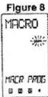
If a macro was previously programmed, one or more of the numeric indicators at the bottom of the LCD window will appear with a box around it.
- Press the MACRO button 1 ⑥ to begin memorizing the various codes. In the LCD display window the indicator "M1-00" appears in the status line ⑥ (see Figure 9).
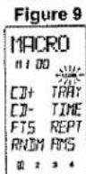
The "M1-00" indication signifies Macro number 1, no steps yet programmed. As each macro step is programmed, the "00" indicator will advance by one digit "01", "02", etc. After the first macro step is programmed, two additional digits (with a decimal in between) become visible at the end of the status line, showing the timing value for each step (see Figure 10).
Figure 10
| CD | |
| M101Q6 | |
| CD | TRY |
| CD- | TIME |
| FTS | REPT |
| RNOH | AMS |
| 0 | ... |
-
Press the command buttons in the desired sequence. When you press a command button to be learned into the macro sequence, its name will appear within the LCD window. Every time you press another remote command, the macro step number increases one by one.
-
It is possible during macro programming to adjust the timing of the interval between several macro steps. Using the cursor keys 16, the interval between macro playback steps can be increased or decreased in 1/2 second steps, over the range beginning at 1/2 second up to 10 seconds. For example, when the indicator shows "0.5 SEC", if you press the direction key, the interval time would change to 10 seconds, then with another press of the direction key, it would change to 9.5 seconds, etc. Use the direction key to increase the interval time, and use the direction key to decrease the interval time.
Some equipment may not be able to receive infrared commands in one-half second steps. If after programming a macro you find that the sequence was not properly carried out, you may wish to experiment with different sequence timings to obtain the correct operation results by using the adjustment method described above.
Within each MACRO button, up to 20 steps can be memorized. In the event that you wish to memorize more than 20 steps per macro, then press another MACRO button [6], and follow the above operations. A maximum of 80 steps can be programmed this way. However, you will probably find that 20 steps is more than enough to carry out even the most complex macro instructions to achieve a specific home theater operating result.
Note:
To memorize the cursor button 16 except OK button, press and hold the LIGHTING button 20 before pressing the cursor button.
When programming macro steps, note that the following buttons would not normally be included in a macro sequence, and are therefore not available for inclusion in a macro:
MODE 1, MACRO 2, CLONE 3, PAGE 8, VOLUME 11, MEMO 13, CLEAR 14 and LIGHTING 20.
To check to see which MACRO buttons [6] have been programmed with macros, at the beginning of the macro learning sequence the four numerical (1 through 4) indicators at the bottom of the LCD window will show a box around the number for each MACRO button that already has a macro assigned to it (see Figure 11, which shows that only MACRO button number 1 has a macro assigned to it).
Figure 11
| PLAY | |
| H 1-03 | Q45 |
| CD+ | TRAY |
| CD- | TIME |
| FTS | REPT |
| RNDM | RMS |
| 0 | 2 |
In the event that you wish to revise a programmed macro sequence, search the step number you wish to change by using the cursor button ▲ and ▼ 16, and then re-enter the new command. If you memorized different commands than have already been programmed, then the previous macro sequence will be erased and re-written over with the new sequence. To add the new command, press the MEMO button at your desired point. To delete the sequence, press the CLEAR button at your desired point.
During macro programming, if a button is not pressed within 1 minute, the mode will automatically revert to the original mode (USE). When you have completed the macro programming sequence, press the MACRO [2] operation button with the tip of a paper clip. The "END" indication appears in the LCD display window. When you release the MACRO button, all indications will revert to the initial status.
There is one more important point to note about programming a macro sequence. During a macro sequence, you may include more than one function selection button to access some transport and/or other commands. Depending on the macro sequence, this might result in the amplifier or receiver's function selection to be
inadvertently changed as well when the macro is played back. The RC-18SR has a special feature to prevent this from occurring, allowing you to access the special commands available under each RC-18SR function button during a macro playback sequence, while at the same time preventing the amplifier or receiver from constantly switching its input source back and forth at the same time.
During the programming sequence, just remember that if you wish to activate a specific input selector on your amplifier or receiver, make sure that you press the desired input selection button FIRST. Subsequent function button selections can be incorporated in the macro sequence, but on playback, the RC-18SR will only send out a function selection infrared command to the amplifier or receiver based upon the first function command used in the macro sequence. For example, you may wish to have a macro sequence which activates the laser disc player input on your amplifier or receiver, and then have additional commands in the sequence to instruct your TV set to switch to an external video source to receive the laser disc video signal. During the macro programming, make sure that you press the LD function selector button BEFORE you press any of the other function selector buttons in the sequence. You can then include any of the TV commands by pressing the TV function selector button, later in the sequence. When this macro is next used (played back), the RC-18SR will send out the command to change the amplifier or receiver's input selector to laser disc input (since its function selector button was the first one programmed into that macro sequence), and will not subsequently change the amplifier or receiver's input to TV (but will send out any special TV commands that you included in the macro sequence).
Programming a macro under a function selector key:
If you wish, you can also program a macro that can be activated by pressing one of the function selector [9] keys. The programming steps are similar to the steps outlined for programming a macro number button [5]. The following example shows how to program a macro under the LD (laser disc) function selector [9]:
(activate the main amplifier's power on, switch the source to laser disc, switch the amplifier's surround mode to PRO LOGIC, switch on the television, switch to the television's AUX video input, power up the laser disc player, and begin laser disc playback)
- Press the MACRO ② operation mode button with the tip of a paper clip.
- Press the LD function button 9.
- Press the following buttons: POWER ON, LD, AMP, direct function D-2 (Dolby mode selector) in page 1, TV*, SOURCE ON, direct function D-3 (VIDEO input selector) in page 1, LD*, SOURCE ON, and PLAY.
- Press the MACRO ② button with the tip of a paper clip. The RC-18SR will revert to the normal mode and save the macro under the LD function button.
- To execute the new macro sequence, press and hold the LD function selector button for 3 seconds.
Using the macro function(s) you have programmed;
- Press the desired MACRO [6] button. The corresponding macro number will appear at the bottom of the display window, OR if a macro has been programmed under a function button, press and hold that function button for 3 seconds. The LCD display window will indicate the macro number in the LCD window (see Figure 12), or if a macro is programmed under a function key, the status line will display the macro under function buttons as follows:
Figure 12
| Macro under function button: | Status line shows: |
| LD | "LD" as the first 2 characters in the line |
| TV | "TV" as the first 2 characters in the line |
| VCR1 | "VC" as the first 2 characters in the line |
| DSS/VCR2 | "DS" as the first 2 characters in the line |
| AUX | "AX" as the first 2 characters in the line |
| TUNER | "TU" as the first 2 characters in the line |
| CD | "CD" as the first 2 characters in the line |
| TAPE | "TP" as the first 2 characters in the line |
| DVD | "DV" as the first 2 characters in the line |
| CD-R/MD | "CR" or "MD"as the first 2 characters in the line |
| AMP | "AP" as the first 2 characters in the line |
- The macro sequence will begin, and the remote control codes will be sent from the RC-18SR and the display will show the names of the transmitted codes.
- When the macro transmit sequence has ended, the RC-18SR will return to the same mode as before the macro function was initiated.
Now that we've explained how to program a macro, perhaps the following suggested example can help you become more familiar with the process:
(to switch the RC-18SR to CD, then initiate CD playback, and go to track 3 on the CD)
- Press the MACRO 2 operation mode button with the tip of a paper clip.
- Press one of the MACRO buttons (1 through 4).
- Press the following buttons:
- CD function selector, then numeric key pad 3, then transport control key pad PLAY key. (see Figures 13, 14, and 15)
Figure 13
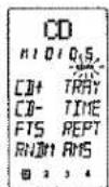
Figure 14
Figure 15
Note that this sequence will operate a Marantz CD player (or any other CD player equipped with the RC-5 remote control language). If you have another brand of CD player, you may wish to check its owner's manual to see if direct track selection is possible via remote, or if the macro sequence needs to be adjusted according to the programming steps required by your CD player.
- Press the MACRO ② button with the tip of a paper clip. The RC-18SR will revert to the normal mode (see Figure 16).
- To execute the new macro sequence, press the appropriate MACRO button (1 through 4) that you chose at the beginning of the above programming sequence. (see Figures 17, 18, and 19)
Figure 17
Figure 18
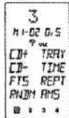
Figure 19
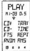
Note:
If you would like to cancel the MACRO function, press the STOP button.
Now, we'll show you another macro programming example, with a more sophisticated sequence:
(activate the main amplifier's power on, switch the source to laser disc, switch the amplifier's surround mode to PRO LOGIC or Dolby Digital, switch on the television, switch to the television's AUX video input, power on the laser disc player, and begin laser disc playback).
- Press the MACRO ② operation mode button with the tip of a paper clip.
- Press one of the MACRO buttons (1 through 4).
- Press the following buttons:
POWER ON, LD, AMP, direct function D-2 (Dolby mode) on page 1, TV*, SOURCE ON, direct function D-3 (VIDEO input selector) on page 1, LD*, SOURCE ON, and PLAY.
- Press the MACRO ② button with the tip of a paper clip. The RC-18SR will revert to the normal mode.
- To execute the new macro sequence, press the appropriate MACRO button (1 through 4) that you chose at the beginning of the above programming sequence.
- Note that the function selector buttons TV and LD marked with an asterisk (*) in this macro sequence do not actually send out infrared codes, but simply change over the RC-18SR's programmed memory code banks for those respective functions.
If you would like to clear the MACRO programmed sequence(s), press and hold the CLEAR 14 button and simultaneously press the appropriate MACRO button (1 through 4) or function button. "MR1-CLR?" (macro 1-clear?) appears in the LCD window. Release the buttons, and then press the OK button (within the cursor control buttons), and the macro is erased. If you do not wish to erase the macro, simply press any other button (but not the OK button).
CLONE mode:
Duplicating the memory contents of one RC-18SR to another RC-18SR or RC2000MKII.
For a complete home theater system, with numerous components from many different manufacturers, you may find that you have stored dozens, even hundreds of different codes, along with specialized names, macros, etc. We have provided a very quick and simple procedure that allows you to download the entire customized memory contents of one RC-18SR remote control into another RC-18SR or RC2000MKII.
To "clone" (duplicate) the memory contents of one RC-18SR
into another RC-18SR or RC2000MKII, please follow these steps:
- Place the source RC-18SR (the one with all of the customized commands, names, macros, macro sequences, etc) with its infrared transmitter window 21 facing the receiving infrared sensor 22 of another "fresh" RC-18SR or RC2000MKII (5 cm, or 2 inches apart).
- Press the CLONE button 3 of the source RC-18SR or RC2000MKII with the tip of a paper clip, and select "CLONE TX" (clone transmit) mode.
Note:
When using RC18SR, "RC2002" is displayed in LCD window. If the receiving remote control unit is RC200CMKJ, then the display does not change. If the receiving remote control unit is RC-18SR, then the display is changed to "RC18SR" by pressing the cursor button ▲ 16 (see Figure 20)
Figure 20
- Press the CLONE button [3] of the learning (receiving) RC-18SR or RC2000MKII with the tip of a paper clip or a similar object, and select "CLONE RX" (clone receive mode).
When using RC18SR, "RC2002" is displayed in LCD window. If the transmitting remote control unit is RC2000MKII, then the display does not change. If the transmitting remote control unit is RC-18SR, then the display is changed to "RC18SR" by pressing the cursor button ▲ 16. Then press the PLAY button [5].
Note:
When the transmitting remote control unit is RC2000MKII, then All clone does not activate. To clone the Function key, press the each Function key except DSS/VCR2 and AMP keys. Eight keys can be cloned at once. If All clone activates without presing the Function button, "N/A" will display and the clone is not performed. When the transmitting remote control unit is RC-18SR and receiving remote control unit is RC2000MKII, The DSS/VCR2, CD-R/MD and AMP keys cannot be cloned. To clone the Function key, press each Function key except DSS/VCR2, CD-R/MD and AMP keys.
Figure 21
- Press the source RC-18SR's or RC2000MKII's transport control PLAY 15 button to begin the infrared data transmission sequence. If you wish to duplicate only 1 to 8 function's memory, press the function button(s) you wish before pressing the PLAY button. Now the "LEARN" indicator of receiving RC-18SR starts to blink. (see Figure 23)
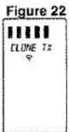
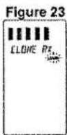
After all bars are lit up on both displays, "TX OK" (transmission OK) will appear in the source RC-18SR's LCD window, and "RX OK" (reception OK) will appear in the "cloned" RC-18SR's LCD window, confirming the end of the copying process (see Figures 24 and 25).
Figure 24
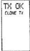
Figure 25
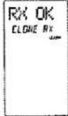
Please be sure that, during the copying process, neither RC-18SR is physically disturbed (ideally, they should be placed on a table or other surface, and not hand-held during the copying process). If, for some reason, the copying process was interrupted, the "clone" RC-18SR's LCD display window will indicate "RX NG" (reception no good). Simply begin the clone process anew by repeating the above steps.
Note:
Cloning is available between the same remote control unit series only therefore the RC-18SR cannot be cloned by the RC2000.
- If the source RC-18SR's memory contents are at or near full capacity, the copying process will take about 3 minutes. After completion of the copying (cloning) process, press the CLONE button ③ on both RC-18SR's with the tip of a paper clip, and select the OFF mode.
Then, you'll have two identically programmed RC-18SR remotes, one of which can again be used as your system's primary remote control, and you'll have the added confidence of knowing that in the event of inadvertent programming (or memory contents being cleared somehow), you can simply retrieve the "backup" RC-18SR that you've safely tucked away, and within minutes restore the programming contents of the original RC-18SR with your customized configuration.
Note:
Some direct keys are marked "♦" in Direct Command Functions Listing (page 25 to 28). The "♦" mark means as follows; When RC-18SR is cloned with RC2000MKII, the name of the direct key can be cloned, however the remote control code (the factory preset code) cannot be cloned. Only learned remote control codes can be cloned. Then the remote control code is learned by "LEARN mode". Refer to page 18.
The table of cloning relations
| Receiving\Transmitting | RC-18SR | RC2000MKII |
| RC-18SR | ALL OK | only FUNC. |
| RC2000MKII | only FUNC. | ALL OK |
ALL OK: All functions can be cloned.
only FUNC.: The following functions cannot be cloned; RC-18SR: DSS/VCR2, CD-R/MD, AMP RC2000MKII: DSS/MD, AMP
OTHER FUNCTIONS
The Marantz RC-18SR includes the ability to tailor the lighting features according to your preferences. As supplied from the factory, the RC-18SR has lighting features (and lighting timings):
The lighting time is set at the factory for a period of 2 seconds which you can change if you prefer a different lighting time. If you wish to maximize battery life, you can de-active the lighting function entirely.
There is also a lighting button 20, so that in any light situation, you can activate the backlighting feature. The lighting time in this case is set at the factory for a period of 2 seconds, which you can also change. If you wish to conserve battery power, you can deactivate the lighting function entirely.
RC-5 Shipped destination:
As mentioned earlier in this guide, the RC-18SR is provided with many commands from the factory with infrared codes conforming to the Philips RC-5 remote control language (used by Marantz, Philips, and some other companies). We have provided two different RC-5 command code sets in the RC-18SR, according to the local requirements of different markets and the different types of remote control codes used in those markets. One code set is for North American (USA) users, while the other code set is for REST users. Your RC-18SR has been set at the factory for USA (United States) codes. It can be easily changed, if you wish.
Set-Up:
To change the lighting time(s), or the destination setting, please follow these steps:
- Select the SETUP mode, by holding the MEMO button 13 and at the same time pressing the OK button within the cursor keys 16. (see Figures 26 and 27)
Figure 26
| SETUP | |
| LRMP | 5 5 |
| BEEP | OFF |
| VER | USA |
| TIMR | 0 M |
Figure 27
| SETUP | |
| LAMP | OFF |
| EEP | +++ |
| VER | REST |
| TIMP | 30 M |
LAMP - Lighting function ON or OFF and TIME
Press the D-5 direct function button, and you can then set the time (in seconds) directly using the numeric key pad [12] buttons. A time figure consisting of only 1 digit can be input by pressing the figure then waiting for 2 seconds or input "0" before entering a desired digit. You can set time in the range from 0 up to 60 seconds (More time would use up more battery life than fewer seconds). "2" is set when shipped from the factory. To set "OFF" input "0".
BEEP sound
The beep sounds when any buttons are pressed except the AMP button.
The beep sound level can be set by pressing the D-6 button. The display indicates "+" indication and the beeps are sounded by pressing the D-6 button. The "+" indication is followed, by another the "+" indication as the beep sound is increased; +→
++→+++→++++
When the "++++" appears, this is the maximum. If the D-6 button is pressed once more, it will reset to OFF.
"J" is indicated in the LCD window when the beep sound is set.
Note:
The beep sound is different between the function buttons and other buttons.
VER
Press the D-7 direct function button to switch between USA and REST.
If you need to change this function, we recommend that you make the change before you begin "learning" any new infrared codes for other brands of equipment in your system.
Note:
The name of the DIRECT buttons will be erased if the USA/REST version is pressed.
Battery life:
- Battery life will vary from user to user, if the remote is used constantly or only occasionally, including the amount of backlighting usage. We feel that you can expect the batteries to last about 4 months, based upon 15 remote control operations per day (every day), and 3 lighting operations per day (every day). If the remote is used more often, and if the lighting times are set to longer times than the factory settings, then the battery life may be shortened somewhat.
- As explained earlier in the guide, the RC-18SR's sophisticated battery conservation system will advise you long before the battery power is fully exhausted, and will further warn you to replace the batteries by simply becoming inoperative at a certain point. The customized memory contents and user-adjusted settings will still be retained in memory. When you install a fresh set of batteries, the memory contents are protected always, because the RC-18SR uses the non-volatile memory. Alkaline (and the newer lithium) types are recommended for longest battery life.
As you become more familiar over time with how you are using the RC-18SR in your A/V system, you may wish to consider reducing the lighting time(s) if possible, as this can help to extend the battery life.
Adjustment of the LCD contrast
- The LCD contrast can be adjusted as follows;
Enter SETUP mode of the RC-18SR by pressing the MEMO and OK button. Press the VOL+ to increase the LCD contrast. Press the VOL - to decrease the LCD contrast. Press the OK button to end this setting and return the original operation.
DIRECT COMMAND FUNCTIONS LISTING
Within the RC-18SR LCD window, each of the 8 Direct Function buttons has 4 character labels attached for pre-programmed remote commands. These commands can be used with various Marantz A/V components, or other components using the Philips RC-5 remote control language.
You can easily replace the factory-supplied remote command codes with different codes from other brands of equipment. Most functions that are supplied apply to a wide variety of equipment from many companies. The following list shows the remote code assignments for the direct function buttons, for each of the 11 main function selector buttons, as supplied from the factory. You can add or replace function commands, including re-naming them if you wish, in order to customize the RC-18SR for your own particular selection of A/V components.
| AMP | 1 MODE-1 | 1 AUTO2 DOLB3 THX4 DTS5 HALL6 MTRX7 MOV8 2-CH | selects Auto select surround modes selects Dolby Digital or Pro Logic decoding selects THX cinema decoding selects DTS decoding Hall surround sound Matrix surround sound Movie surround sound Stereo sound (no surround) |
| 2 MODE-2⊗ | 1 A/D2 DIR3 ATT4 OSD5 MONO6 3-D7 NITE8 MLTI | switches analog / digital input switches source direct switches attenuater for analog input switches on screen display monaural decoding 3-D surround decoding selects NIGHT mode for Dolby Digital activates multi-room mode | |
| 3 MODE-3⊗ | 1 TRB+2 TRB-3 BAS+4 BAS-5 R-EQ6 CH+7 LVL+8 LVL- | increases treble decreases treble increases bass decreases bass activates RE-EQ function next channel (up) increases channel level volume decreases channel level volume | |
| 4 PROCESSOR⊗⊗ | 1 VOL+2 VOL-3 6-CH4 BYP5 SLEP6 DISP7 MODE⊗8 PHNO | increases external decoder's volume decreases external decoder's volume activates 6 channel setup bypasses external processor's decoding activates sleep timer function activates display off function selects surround mode selects phono function | |
| TUNER | 1 BAND⊗⊗⊗ | 1 FM2 AM3 LW4 BAND5 MODE⊗6 TIME7 F/P8 SCAN | FM bandAM/MW bandlong wave band selects radio band mono/stereo/muting mode selector time display frequency or preset channel display programmed preset channel scan |
The marked "⊗" keys are not used for SR-19.
See page 23 to refer the marked "♦" keys.
| TUNER | 2 REC | 1 TP-12 REC3 PAUS4 STOP5 TP-26 REC7 PAUS8 STOP | commands for Tape 1 control (NO output)recordpausestopcommands for Tape 2 control (NO output)recordpausestop |
| 3 RDS(for REST only) | 1 STM2 AF3 PTY4 DISP5678 DWR | selects station modeselects AF functionselects PTY functionselects display functionselects DSR wave range | |
| CD | 1 MODE | 1 CD+2 CD -3 TEXT4 RNDM5 TRAY6 TIME7 RCL8 AMS | CD changer next discCD changer previous discactivates text functionrandom (shuffle) play functiontray open/closetime display elapsed/remaining/totalrecall program memoryautomatic music scan |
| 2 CHANGER1 | 1 CD12 CD23 CD34 CD45 CD56 EDIT7 REPT8 CNCL | selects Disc 1selects Disc 2selects Disc 3selects Disc 4selects Disc 5tape edit functionrepeat functioncancel track programming | |
| 3 CHANGER2 | 1 UNIT2 DISC3 TR4 CATG5 MODE6 TITL7 T-S8 ENT | selects unit No.selects disc No.selects track No.selects categoryselects modeselects function title modeselects title searchselects enter | |
| 4 REC | 1 TAPE2 REC3 PAUS4 STOP5 MD6 REC7 PAUS8 STOP | commands for Tape control (no output)recordpausestopcommands for MD control (no output)recordpausestop | |
| TAPE | 1 MODE | 1 TP-A | selects tape deck A |
| TAPE | 1 MODE | 2 TP-B3 DIR4 TIME5 TRAY6 AMS7 REC8 PAUS | selects tape deck Bauto-reverse directiontime displaytray open/closeautomatic music scanrecordpause |
| DVD | 1 MODE1 | 1 ANGL2 TITL3 SUBT4 MENU5 OSD6 AUD7 SET8 RTN | selects angieselects title menuselects subtilselects main menuactivates on screen displayselects audioselects setup menureturns to menu |
| 2 MODE2 | 1 SLOW2 LPLY3 RNDM4 RPT5 A/B6 +107 T/C8 ZOOM | slow forwardlast play functionshuffle play functionrepeat modesrepeat A to Bdigit entry +10title and chapterzoom mode on/off | |
| 3 KARAOKE | 1 ONOF2 ONCE3 MELO4 VOCL5 MODE6 3-D7 VSLF8 VSLR | karaoke on/offonce more play againmelody playvocal support playkaraoke modessurround processor on/offvery slow forwardvery slow reverse | |
| 4 REC | 1 VCR12 REC3 PAUS4 STOP5 MD6 REC7 PAUS8 STOP | selects VCR1 control (no output)recordpausestopselects MD control (no output)recordpausestop | |
| LD | 1 MODE | 1 SD-A2 SD-B3 DISP4 AMS5 RPTA6 RPTB7 CP/F8 EDIT | side Aside Bdisplay on/offautomatic music scanRepeat A start pointRepeat B stop pointselects chapter or flameactivates tape edit function |
| 2 LD | 1 MSP+2 MSP-3 FRM+4 FRM- | increases CAV multi-speeddecreasesCAV multi-speedframe advanceframe reverse |
| LD | 2 LD | 5 MS-F6 MS-R7 AUD8 D/CX | CAV multi-speed forward directionCAV multi-speed reverse directionStereo, left only, right only channeldigital audio, analog audio, CX NR |
| 3 REC | 1 VCR12 REC3 PAUS4 STOP5 VCR26 REC7 PAUS8 STOP | commands for VCR 1 control(NO output)recordpausestopcommands for VCR 2 control(NO output)recordpausestop | |
| 4 VCD(for REST only) | 1 PBC2 KARA3 IDX+4 IDX-5 SEL6 RTN7 NEXT8 PREV | selects playback controlselects karaokeindex upindex downplay or select audiostop or select returnnext trackprevious track | |
| TV | 1 MODE(for USA only) | 1 A/CH2 100S3 VID4 INFO5 VOL+6 VOL-7 MUTE♦8 OSD | alternate channel100'svideoinformationincreases TV volumedecreases TV volumemute sound on/offactivates on screen display |
| 2 MODE/MENU(for USA only) | 1 S-PI2 S-SO3 S-CH45 MENU6 ADV7 STAT8 | smart picturesmart soundsmart channelmenuadvancestatus | |
| 3 PIP1(for USA only) | 1 PIP2 SWAP3 FREZ4 POSI5 SIZE6 STRO7 PREV8 RPLY | PIP on/offPIP swapPIP freezePIP positionPIP sizePIP strobePIP previewPIP instant replay | |
| 4 PIP2/REC(for USA only) | 1 CLR2 SLOW345 VCR1 | PIP clearPIP slow motion | |
| TV | 4 PIP2/REC | 6 REC7 PAUS8 STOP | recordpausestop |
| TV | 1 MODE(for REST only) | 1 CH +2 CH -3 CH-C4 VID5 VOL+6 VOL-7 MUTE8 OSD | next channel (up)previous channel (down)channel callexternal (aux) video inputincreases TV volumedecreases TV volumemute sound on/offon screen display on/off |
| 2 MENU/CBL(for REST only) | 1 MENU2 SLP3 CBL +4 CBL -5 ADV6 STAT7 M-UP8 M-DN | activates menuactivates sleep timercable tuning next channelcable tuning previous channeladvances to next menu pageshows current statusMenu up (next)Menu down (previous) | |
| 3 REC(for REST only) | 1 VCR12 REC3 PAUS4 STOP5 VCR26 REC7 PAUS8 STOP | commands for VCR 1 control recordpausestopcommands for VCR 2 control(NO output)recordpausestop | |
| 4 TV TXT(for REST only) | 1 T/PG2 HOLD3 ENLG4 RVL5 CNCL6 PG+7 PG-8 ENT | switches time displayactivates page holdselects large of text pageselects display of text pageactivates cancel pictureincreases pagedecreases pageenters the next page | |
| VCR1 | 1 MODE | 1 CH+2 CH-3 SLCT4 AUD5 OTR6 REC7 PAUS8 STOP | next channel (up)previous channel (down)selects TV or VCRaudio track selectorone touch recordingrecordpausestop |
| 2 PLAYMODE | 1 2XPL2 SLOW3 STIL45 SKIP6 VIS+7 VIS- | twice normal playback speedslower than normal playback speedstill frameskip to next program markerVHS index search nextVHS index search previous |
| VCR1 | 2 PLAYMODE | 8 | |
| 3 MENU | 1 MENU2 STAT3 CLR4 GOTO5 PLUS678 | activates menushows current statusclear programminggo to next itemvideo PLUS | |
| DSS | 1 DSS | 1 DISP2 PREV3 CH+4 CH-5 FAV6 ALT7 FTCH8 ANT | brings up on screen channel marker goes to previously selected channel next channelprevious channelfavorite users and channel listsalternate audio channel, languages brings up on screen channel logos selects broadcast or cable antenna |
| 2 MODE | 1 CH+2 CH-3 SLCT4 AUD5 OTR6 REC7 PAUS8 STOP | next channelprevious channelselects TV or VCRaudio track selectorone touch recordingrecordpausestop | |
| 3 PLAY MODE | 1 2XPL2 SLOW3 STIL45 SKIP6 VIS+7 VIS-8 | two times play speedslow speed playstill frameskip to next programVHS index search nextVHS index search previous | |
| 4 MENU | 1 MENU2 STAT3 CLR4 GOTO5678 | activate menushow current statusclear programminggo to next item | |
| AUX | 1 REC | 1 VCR12 REC3 PAUS4 STOP5 VCR26 REC7 PAUS8 STOP | commands for VCR 1 control (NO output)recordpausestopcommands for VCR 2 control (NO output)recordpausestop |
| AUX | 2 VCD/PHI 1(for REST only) | 1 CD+2 CD-3 OSD4 SCAN5 A/B6 SLOW78 | selects disc upselects disc downOSD on/offselects time searchrepeat A to Bslow forward |
| 3 VCD/PHI 2(for REST only) | 1 PBC2 KARA3 IND+4 IND-5 SEL6 RTN7 NEXT8 PREV | selects playback controlselects karaoke programselects video index upselects video index downselects in PBCreturns in PBCnextprevious | |
| 4 VCD/PHI 3(for REST only) | 1 CD+2 SHUT3 OVEW4 RESM5 CHAN6 FADR78 | selects disc upselects shutter functionselects digest functionselects last paly functionselects channelselects MPX/vocal fader | |
| MD(for REST only) | 1 MODE 1 | 1 MD-A2 MD-B3 RPT4 DISP5 EJCT6 AMS7 RNDM8 LP | selects MD Aselects MD Bselects repeat modesselects display modesejectautomatic music scanrandom displayselects SP/LP mode |
| 2 EDIT | 1 EDIT2 CHAR3 DEL4 ENT5 AMRK6 SYNC7 PROG8 | selects edit modeselects character modeselects deleteselects enterselects auto markersyncro RECselects program mode | |
| 3 REC | 1 MD2 RECP3 PAUS4 STOP5 TAPE6 REC7 PAUS8 STOP | command MD (no output)REC-pausepausestopcommand tape (no output)recordpausestop | |
| CD-R(for USA only) | 1 REC | 1 INPT2 INCR3 SYNC | selects input sourceincrements track numberactivates SYNCRO, recording |
| CD-R | 1 REC | 4 REC5 TRAY6 DISP7 FINL8 BLNK | records pauseopens/closes traydispaly modefinalizes (writes TOC)records blank |
| 2 MODE | 1 PROG2 REPT3 FTS4 FAST5 VOL+6 VOL-7 IDX+8 IDX- | activates program modeactivates repeat modeactivates FTS modesearches FASTincreases volumedecreases volumeincreases indexdecreases index |
SURROUND MODES
The SR-19 incorporates digital signal processors (DSP) which can reproduce various surround effects you experience in concert halls and move theaters, etc. Nine Surround Modes, are provided to reproduce a variety of surround sound effects, according to the content of the source to be played
| FEATURES | |
| 1. STEREO | This mode disables all surround processing.Left and right channels play as is when PCM-audio or analog stereo is input.Even when playing multi-channel encoded Dolby Digital and DTS sources, the multi-channels are mixed down to two channels, left and right, before being output. |
| 2. MONO | This mode is intended for use with old movies, televisions shows and other programs that have a monaural sound track. All sound will be reproduced through the center channel speaker, if installed. Even when playing multi-channel encoded Dolby Digital and DTS sources, the multi-channels are mixed down to monaural channel, center, before being output. If there is no center speaker, monaural sound is reproduced from the front left and right speakers. However output will be muted when 96 kHz PCM signal is input. |
| 3. DOLBY | This mode is enabled when playing source materials encoded in Dolby Digital and Dolby Surround.Playing multi-channel encoded 5.1-channel Dolby Digital sources provides five main audio channels (left, center, right, surround left and surround right) and Low Frequency Effect channel.Dolby Pro Logic processing is performed on Dolby Surround encoded two channel signals (Dolby Digital two channels, PCM-audio and Analog stereo). This allows play of the four discrete channels (left, center, right and surround).Note:PCM-audio signals can be subjected to Pro Logic processing when the sampling frequency is 32 kHz, 44.1 kHz or 48 kHz. However output will be muted when 96 kHz PCM signal or DTS signal are input. |
| 4. DTS(Cinema)(Music) | This mode is valid only for DTS digital signal input and from DTS encoded source materials such as LASER DISC, CD, and DVD.Playing 5.1-channel multi-channel encoded DTS sources provides five main audio channels (left, center, right, surround left and surround right) and the Low Frequency Effect channel.On DTS Music mode, LFE signal is less than 10 dB. If you playback DTS music material, you should select the DTS Music.When a signal in another format is input, output will be muted.This mode cannot be used when Analog input has been selected. |
| 5. MOVIEHALLMATRIX | These modes provide surround effect processing in addition to Dolby Digital, DTS and Pro Logic decoding.They will produce theater-, concert-hall- and stadium-like atmospheres. Select as your taste requires.Note:PCM-audio signals can be processed in this mode when sampling frequency is 32 kHz, 44.1 kHz or 48 kHz. The 96 kHz. sampling frequency mutes output. |
| 6. THX CINEMA | THX Cinema surround mode applies additional processing to Dolby Digital, DTS, and Dolby Pro Logic multi-channel surround sources. The THX processing was developed by Lucasfilm Ltd. to recreated the sound of top-quality theater. Use the THX Cinema mode for all movies on disc, tape or broadcast.Note:PCM-audio signals can be subjected to THX processing when the sampling frequency is 32 kHz, 44.1 kHz or 48 kHz. However output will be muted when 96 kHz PCM signal is input. |
| 7. AUTO | When this mode is selected, the program automatically switches playback mode according to type of digital input signal and then determines whether the digital input signal is Dolby Digital, PCM-audio or DTS to play the corresponding sound.When a Dolby Digital or DTS signal is input, the number of channels for which the corresponding signal is encoded will be played.Note:Inputting a Dolby Digital two channel signal with Dolby surround status automatically subjects that signal to Pro Logic processing before play.Inputting a PCM-audio signal plays stereo. |
Caution for DTS signal:
This signal can be played when the connected DVD-player, laser-disc player or CD-player responds to DTS-digital output. For details, refer to the player's operation manual.
Depending on the player used, DTS play may produce noise. If that happens, set the Surround mode to DTS.
Playing a DTS-CD or DTS laser disc causes the player's analog output terminal to output noise. Before playing DTS sources, be sure to connect the player's digital output to this machine's digital input. Be careful when connecting the output of these players to analog audio input.
Note that this machine has the following restrictive functions built in to reduce noise emission as much as possible.
If DTS is selected while in Surround mode, digital input cannot be switched to analog input. When the analog input function has been selected, Surround mode cannot be switched to DTS.
While signals from DTS-laser disc or CD are playing in another Surround mode, you cannot switch to digital input or from digital input to analog input.
Caution for 96kHz PCM-audio signal:
This signal can be played when a DVD-player or DAT-player connected to this machine responds to 96 kHz PCM output. For details, refer to the player's operation manual.
The signal can be played when STEREO or AUTO has been selected for the Surround mode.
Some DVD formatted discs are featured copy protect. When there such disc, 96 kHz PCM signal is not output from the DVD player. For details, refer to the player's operation manual.
The relation between the selected surround mode and the input signal
The surround mode is selected with the surround mode buttons of SR-19 or the remote control unit. However, the sound of the speaker is as the relation between the selected surround mode and input signal. The relations are as follows;
| Set Mode | Input Signal | Bass manager | Output | Fluorescent Indicator | LED Indicator | ||||||
| L/R | LS/RS | C | SW | Encoded | Mode | other status | Ch. Status | other | |||
| AUTO | Dolby Digital (5.1 ch) | ○ | ○ | ○ | ○ | ○ | ☐☐ | D-Digital, Auto | - | 3/2.1 | - |
| Dolby Digital (2 ch) | ○ | ○ | - | - | ○ | ☐☐ | D-Digital, Auto | - | 2/0 | - | |
| Dolby Digital (2 ch: Lt/Rt) | ○ | ○ | ○ | ○ | ○ | ☐☐ | Pro Logic, Auto | - | 2/1 | - | |
| PCM-audio (Fs=96k) | - | ○ | - | - | ○ | PCM | Stereo, Auto | - | 2/0 | 96kHz | |
| PCM-audio (Fs=32k, 44.1k, 48k) | ○ | ○ | - | - | ○ | PCM | Stereo, Auto | - | 2/0 | - | |
| DTS (5.1 ch) | ○ | ○ | ○ | ○ | ○ | DTS | Auto | - | 3/2.1 | dis, cinema | |
| Analog | - | ○ | - | - | ○ | - | Stereo, Auto | - | - | - | |
| DOLBY | Dolby Digital (5.1 ch) | ○ | ○ | ○ | ○ | ○ | ☐☐ | D-Digital | - | 3/2.1 | - |
| Dolby Digital (2 ch) | ○ | ○ | ○ | ○ | ○ | ☐☐ | Pro Logic | - | 2/1 | - | |
| Dolby Digital (2 ch: Lt/Rt) | ○ | ○ | ○ | ○ | ○ | ☐☐ | Pro Logic | - | 2/1 | - | |
| PCM-audio (Fs=96k) | - | - | - | - | - | (PCM) | D-Digital | - | - | 96kHz | |
| PCM-audio (Fs=32k, 44.1k, 48k) | ○ | ○ | ○ | ○ | ○ | PCM | Pro Logic | - | 2/0 | - | |
| DTS (5.1 ch) | - | - | - | - | - | (DTS) | D-Digital | No data | - | - | |
| Analog | ○ | ○ | ○ | ○ | ○ | - | Pro Logic | - | - | - | |
| THX Cinema | Dolby Digital (5.1 ch) | ○ | ○ | ○ | ○ | ○ | ☐☐ | D-Digital, THX cinema | - | 3/2.1 | - |
| Dolby Digital (2 ch) | ○ | ○ | ○ | ○ | ○ | ☐☐ | Pro Logic, THX cinema | - | 2/1 | - | |
| Dolby Digital (2 ch: Lt/Rt) | ○ | ○ | ○ | ○ | ○ | ☐☐ | Pro Logic, THX cinema | - | 2/1 | - | |
| PCM-audio (Fs=96k) | - | - | - | - | - | (PCM) | THX cinema | - | - | 96 kHz | |
| PCM-audio (Fs=32k, 44.1k, 48k) | ○ | ○ | ○ | ○ | ○ | PCM | Pro Logic, THX cinema | - | 2/0 | - | |
| DTS (5.1 ch) | ○ | ○ | ○ | ○ | ○ | DTS | THX cinema | - | 3/2.1 | dis, cinema | |
| Analog | ○ | ○ | ○ | ○ | ○ | - | Pro Logic, THX cinema | - | - | - | |
| DTS Cinema | Dolby Digital (5.1 ch) | - | - | - | - | - | (DD) | - | No data | - | dis, cinema |
| Dolby Digital (2 ch) | - | - | - | - | - | (DD) | - | No data | - | dis, cinema | |
| Dolby Digital (2 ch: Lt/Rt) | - | - | - | - | - | (DD) | - | No data | - | dis, cinema | |
| PCM-audio (Fs=96k) | - | - | - | - | - | (PCM) | - | No data | - | 95kHz, dis, cinema | |
| PCM-audio (Fs=32k, 44.1k, 48k) | - | - | - | - | - | (PCM) | - | No data | - | dis, cinema | |
| DTS (5.1 ch) | ○ | ○ | ○ | ○ | ○ | DTS | - | - | 3/2.1 | dis, cinema | |
| Analog | - | - | - | - | - | - | - | - | - | dis, cinema | |
| DTS Music | Dolby Digital (5.1 ch) | - | - | - | - | - | (DD) | - | No data | - | dis, music |
| Dolby Digital (2 ch) | - | - | - | - | - | (DD) | - | No data | - | dis, music | |
| Dolby Digital (2 ch: Lt/Rt) | - | - | - | - | - | (DD) | - | No data | - | dis, music | |
| PCM-audio (Fs=96k) | - | - | - | - | - | (PCM) | - | No data | - | 96kHz, dis, music | |
| PCM-audio (Fs=32k, 44.1k, 48k) | - | - | - | - | - | (PCM) | - | No data | - | dis, music | |
| DTS (5.1 ch) | ○ | ○ | ○ | ○ | ○ | DTS | - | - | 3/2.1 | dis, music | |
| Analog | - | - | - | - | - | - | - | - | - | dis, music | |
| HALL MATRIX MOVIE | Dolby Digital (5.1 ch) | ○ | ○ | ○ | ○ | ○ | ☐☐ | Movie, Hall or Matrix | - | 3/2.1 | - |
| Dolby Digital (2 ch) | ○ | ○ | ○ | ○ | ○ | ☐☐ | Movie, Hall or Matrix | - | 2/0 | - | |
| Dolby Digital (2 ch: Lt/Rt) | ○ | ○ | ○ | ○ | ○ | ☐☐ | Movie, Hall or Matrix | - | 2/0 | - | |
| PCM-audio (Fs=96k) | - | - | - | - | - | (PCM) | Movie, Hall or Matrix | - | - | 96 kHz | |
| PCM-audio (Fs=32k, 44.1k, 48k) | ○ | ○ | ○ | ○ | ○ | PCM | Movie, Hall or Matrix | - | 2/0 | - | |
| DTS (5.1 ch) | ○ | ○ | ○ | ○ | ○ | DTS | Movie, Hall or Matrix | - | 3/2.1 | - | |
| Analog | ○ | ○ | ○ | ○ | ○ | - | Movie, Hall or Matrix | - | - | - | |
| STEREO | Dolby Digital (5.1 ch) | ○ | ○ | - | - | ○ | ☐☐ | STEREO | - | 3/2.1 | - |
| Dolby Digital (2 ch) | ○ | ○ | - | - | ○ | ☐☐ | STEREO | - | 2/0 | - | |
| Dolby Digital (2 ch: Lt/Rt) | ○ | ○ | - | - | ○ | ☐☐ | STEREO | - | 2/0 | - | |
| PCM-audio (Fs=96k) | - | ○ | - | - | ○ | PCM | STEREO | - | 2/0 | 96 kHz | |
| PCM-audio (Fs=32k, 44.1k, 48k) | ○ | ○ | - | - | ○ | PCM | STEREO | - | 2/0 | - | |
| DTS (5.1 ch) | ○ | ○ | - | - | ○ | DTS | STEREO | - | 3/2.1 | - | |
| Analog | ○ | ○ | - | - | ○ | - | STEREO | - | - | - | |
| MONO | Dolby Digital (5.1 ch) | ○ | - | - | ○ | ○ | ☐☐ | MONO | - | 3/2.1 | - |
| Dolby Digital (2 ch) | ○ | - | - | ○ | ○ | ☐☐ | MONO | - | 2/0 | - | |
| Dolby Digital (2 ch: Lt/Rt) | ○ | - | - | ○ | ○ | ☐☐ | MONO | - | 2/0 | - | |
| PCM-audio (Fs=96k) | - | - | - | - | - | (PCM) | MONO | - | - | 96 kHz - | |
| PCM-audio (Fs=32k, 44.1k, 48k) | ○ | - | - | ○ | ○ | PCM | MONO | - | 2/0 | - | |
| DTS (5.1 ch) | ○ | - | - | ○ | ○ | DTS | MONO | - | 3/2.1 | - | |
| Analog | ○ | - | - | ○ | ○ | - | MONO | - | - | - | |
| S-Direct | Dolby Digital (5.1 ch) | - | - | - | - | - | (DD) | "DIRECT",STEREO | no audio | - | - |
| Dolby Digital (2 ch) | - | - | - | - | - | (DD) | "DIRECT",STEREO | no audio | - | - | |
| Dolby Digital (2 ch: Lt/Rt) | - | - | - | - | - | (DD) | "DIRECT",STEREO | no audio | - | - | |
| PCM-audio (Fs=96k) | - | ○ | - | - | - | PCM | "DIRECT",STEREO | - | 2/0 | 96 kHz | |
| PCM-audio (Fs=32k, 44.1k, 48k) | - | ○ | - | - | - | PCM | "DIRECT",STEREO | - | 2/0 | - | |
| DTS (5.1 ch) | - | - | - | - | - | (DTS) | "DIRECT",STEREO | no audio | - | - | |
| Analog | - | ○ | - | - | - | - | "DIRECT",STEREO | - | - | - | |
Note: Dolby Digital (2 ch: Lt/Rt): signal with Dolby Surround flag.
L/R : Front speaker
( ): The indicator blinks
LS/RS: Surround speaker
C : Center speaker
SW : Sub woofer speaker
TROUBLESHOOTING
In case of trouble, check the following before calling for service:
-
Are the connections made properly?
-
Are you operating the unit properly following user's guide?
- Are the power amplifiers and speaker working properly?
If the unit does not operate properly, check items shown in the following table.
If your trouble cannot be recovered with the remedy actions listed in the following table, malfunction of the internal circuitry is suspected; immediately unplug the power cable and contact your dealer, nearest Marantz distributor or the Marantz Service Center in your country.
| SYMPTOM | CAUSE | REMEDY |
| SR-19 cannot be turned up. | The power plug is not connected. | Connect the power plug to the outlet. |
| No sound and picture are output even when power is on. | Mute is on.The input cable is not connected correctly.The master volume control is turned all the way down.The function selector position is wrong. | Cancel mute using the remote control unit.See the connection diagram and connect the cables correctly.Adjust the master volume.Select correct position. |
| Speaker not outputting any sound. | The headphones are connected to the headphone jack. | Disconnect the headphones. (Speakers will not output sound when headphones are connected.) |
| Sound and pictures from other than equipment selected with the function selector. | Input cable connected incorrectly. | Connect the cable correctly by referring to the connection diagram. |
| Sound from the wrong channel is output from the speaker. | Speaker cable connected incorrectly. | Connect the cable correctly by referring to the connection diagram. |
| No sound is output from the center speaker. | The center speaker cable connection is incomplete.STEREO has been selected for Surround mode.Center = NONE has been selected in SETUP mode. | Connect the cable correctly.When STEREO is selected for Surround mode, no sound will be output from the center speaker. Set another Surround mode.Make the correct setting. |
| No sound is output from the surround speaker. | The surround speaker cable connection is incomplete.STEREO has been selected for Surround mode.Surround = NONE has been selected in SETUP mode. | Connect the cable correctly.When STEREO has been selected for Surround mode, no sound will be output from the surround speaker. Set another Surround mode.Make the correct setting. |
| No output to Sub Woofer Out. | Sub-woofer = NONE has been selected in SETUP mode. | Select Sub-woofer = YES. |
| Surround mode cannot be changed. | The headphones are connected to the jack. | Disconnect the headphones. (When headphones are connected, Surround mode will be fixed to STEREO.) |
| Noise is produced during DTS-encoded CD or laser disc play. | Analog has been selected for input. | Be sure to perform digital connection, select digital input, then play. |
| DTS sources cannot be played. | Surround mode is set to DOLBY.The player does not respond to DTS digital out. | Select other mode.Use a player which responds to DTS-digital out. |
| Player skips during play of a DTS source and produces noise. | Data error occurred during player skip. | Set Surround mode to DTS-cinema or DTS-music.. |
| A 96kHz PCM signal cannot be played. | The player does not respond to 96kHz PCM digital out.Surround mode is set to other than STEREO and AUTO. | Use a player that responds to 96kHz PCM digital out.Set Surround mode to STEREO or AUTO. |
| A normal PCM signal (CD or laser disc) cannot be played. | Surround mode is set to DTS-cinema or DTS-music. | Select other mode. |
| A Dolby Digital signal cannot be played. | Surround mode is set to DTS-cinema or DTS-music. | Select other mode. |
| A specific channel does not produce output. | Nothing recorded on source. | Check the encoded channel on the source side. |
| FM or AM reception fails. | Antenna connection is incomplete. | Correctly connect the indoor FM and AM antennas to FM and AM antenna outlets. |
| Noise is heard during AM reception. | Reception is affected by other electrical fields. | Try changing location where the AM indoor antenna is set up. |
| Noise is heard during FM reception. | The radio waves from the broadcasting station are weak. | Install an FM outdoor antenna. |
| Cannot get programmed station when the PRESET button is pressed. | Preset data has been erased. | Disconnecting power plug for long periods of time will erase preset data. If that happens, input the preset data again. |
| Nothing appears on the remote commander display. | Batteries are consumed. | Replace all the batteries with new ones.- |
| Control with the remote control unit fails. | Batteries are consumed..Remote controller's function-key setting is wrong.The distance between this SR-19 and the remote commander is too far.Something is blocking SR-19 and the remote commander. | Replace all the batteries with new ones..Select different position from which equipment will be controlled.Move closer to this SR-19.Remove offending object. |
GENERAL MALFUNCTION
If the equipment malfunctions, this may be because an electrostatic discharge or AC line interference has corrupted the information in the equipment memory circuits. Therefore:
- disconnect the plug from the AC line supply
- after waiting at least three minutes, reconnect the plug to the AC line supply
- re-attempt to operate the equipment
ERROR MESSAGES
When the display indicates some error messages (e.g. ERROR **), unplug the power cable immediately. Contact your dealer, nearest Marantz distributor or the Marantz service center in your area.
HOW TO RESET THE UNIT
Should the operation or display seem to be abnormal, reset the unit with the following procedure.
The SR-19 is turned on, press and hold the CL (CLEAR) ⑨ and DISPLAY OFF buttons ⑩ simultaneously for 3 seconds or more.
Remember that the procedure will reset the settings of the function selector, Surround mode, delay time, TUNER PRESET etc., to their initial settings.
Memory backup
- In case a power outage occurs or the power cord is accidentally unplugged, the SR-19 is equipped with a backup function to prevent memory data such as the preset memory from being erased.
The memory functions are backed up for up to about one week.
NOTE:
First of all keep SR-19 Standby or Powered-on more than 6 hours, to sufficient time for memory back up.
TECHNICAL SPECIFICATIONS
FM TUNER SECTION
Frequency Range 87.5 - 108.0 MHz
Usable Sensitivity IHF 1.8 μV/16.4 dBf
Signal to Noise Ratio .... Mono/Stereo 76/72 dB
Distortion ...... Mono/Stereo 0.2/0.3 %
Stereo Separation 1 kHz 45 dB
Alternate Channel Selectivity ± 400 kHz 60 dB
Image Rejection 98 MHz 70 dB
Tuner Output Level 1 kHz, ±75 kHz Dev 800 mV
AM TUNER SECTION
Frequency Range 520 - 1710 kHz
Signal to Noise Ratio 50 dB
Usable Sensitivity .... Loop 400 μV
Distortion 1 kHz, 30 % Mod. 0.5 %
Selectivity ±20 kHz 70 dB
AUDIO SECTION
Continuous Power Output
FRONT (20 Hz - 20 kHz) 8 ohms 110W / Ch
Center (20 Hz - 20 kHz) 8 ohms 110W / Ch
Surround (20 Hz - 20 kHz) 8 ohms 110W / Ch
THD Front (20 Hz - 20 kHz) 8 ohms 0.05 %
Input Sensitivity/Impedance
Linear 350 mV/47 Kohms
Signal to Noise Ratio
Linear 105 dB
VIDEO
Television Format NTSC
Input Level/impedance 1 Vp-p/75 ohms
Output Level/Impedance 1 Vp-p/75 ohms
Video Frequency Response 5 Hz to 8 MHz (-1 dB)
S/N 60 dB
GENERAL
Power Requirement AC 120 V 60 Hz
Power Consumption (STEREO MODE RATED POWER) 440 W
Dimension (MAX)
Width.... 18 inches (458 mm)
Height 7-1/2 inches (190 mm)
Depth 19-1/2 inches (496 mm)
Weight 48.6 lbs (22.0 Kg)
ACCESSORIES
Remote Control Unit RC-18SR 1
AA-size batteries 4
FM Feeder Antenna 1
FM Antenna Converter 1
AM Loop Antenna....1
Specifications subject to change without prior notice.
| COUNTRY | COMPANY | ADDRESS |
| AUSTRALIA | Scan audio Pty. Ltd. | 4 Station Street, Thornleigh NSW 2120, Australia |
| AUSTRIA | Huber & Prohaska GmbH | Taborstraße 95 / Ladestraße 1, Gebäude Hangartner, A-1200 Wien, Austria |
| BELGIUM | Van der Heyden Audio N.V. | Brusselbaan 278, 9320 Erembodegem, Belgium |
| BULGARIA | Ariescommerce GmbH | Makedonia Blvd. 16, 1606 Sofia, Bulgaria |
| CANADA | Lenbrook industries Limited | 633 Granite Court, Pickering, Ontario |
| CYPRUS | Empire Hifi systems Ltd. | P.O. Box 5604, Nicosia, Cyprus |
| CZECH REPUBLIC | Audio International | Fugnerova 1, 67801 Blansko, Czech Republic |
| DENMARK | Hi-Fi Klubben Denmark | Aboulevarden 1, DK-8000 Arhus C., Denmark |
| DUBAI | V.V.& SONS | P.O. Box 105, Dubai, U.A.E. |
| ESTONIA | Audio International Baltic | Lo Hu 12, EE0026 Tallin, Estonia |
| F.Y.R.O.M. | T.P. KODI | ul.Cedomir Kantargiev 21a, Skopje, Former Yugoslavian Republic of Macedonija |
| FINLAND | Hi-Fi Klubi Finland | Uudenmaankatu 4-6, SF-00120 Helsinki, Finland |
| FRANCE | Marantz France | A division of Marantz Europe B.V., P.O. Box 301, 92 156 Suresnes Cedex, France |
| GERMANY | Marantz Deutschland | Hakenbusoh 3, 49078 Osnabrück, Germany |
| GREECE | Adamco S.A. | 188, Hippocratous Street, 11471 Athens, Greece |
| HEADQUARTERS EUROPE: | Marantz Europe B.V. | Building SFF-2, P.O. Box 80002, 5600 JB Eindhoven, The Netherlands |
| HONG KONG | Marantz Asia Ltd. | Unit 1706, Metroplaza II, 223 Hing Fong Road, Kwai Fong, N.T., Kowloon, Hong Kong |
| HUNGARY | Infovox Ltd. | Terez Krt.31, 1067 Budapest, Hungary |
| ICELAND | Radiobudin HF | Skipholli 19, P.O. Box 424, 121 Reykjavik, Iceland |
| INDIA | Marantz India | c/o Philips India Ltd., Plot 80, Bhosari Industrial Estate Pune - 411026, India |
| IRAN | Home Co. | 5th floor no 878 Philips Building Enghelab ave, P.O. 11365/7844 Tehran, Iran |
| IRELAND | Marantz Ireland | Clonskeagh, Dublin 14, Ireland |
| ISRAEL | Elmor Ltd. | 52 Heh Beiyar Street, Kikar Hamedina, Tel Aviv, Israel |
| ITALY | Marantz Italy | Via Casati 23, 20052 Monza (Milano), Italy, Servizio Consumatori 1678-20026, Numero Verde |
| JAPAN | Marantz Japan Inc. | 35-1 Sagami Ohno 7-Chome, Sagamihara-shi, Kanagawa 228-8505, Japan |
| KOREA | Mk Enterprises Ltd. | #604 Electro-officetel, 16-58, 3GA Hangang-ro, Yongsan-ku, Seoul 140-013 Korea |
| KUWAIT | alAlamiah Electronics Intl. | P.O. Box 8196, Saimlah 22052, Kuwait |
| LATVIA | Ace Ltd. | 61, LacPlesa Str., Riga LV 1011, Latvia |
| LEBANON | AZ Electronics S.A., 1. | P.O. Box 11 2833, Beirut, Lebanon |
| LITHUANIA | A Accapella Ltd. | Ausros, Vartu G5, Pasazo Skg., 2001 Vilnius, Lithuania |
| MALAYSIA | Wo Kee Hong Electronics Sdn. Bhd. | 102 Jalan SS 21/35, Damansara Utama, 47400 Petaling Jaya, Selangordarul Ehsan, Malaysia |
| MALTA | Doneo Co Ltd. | 78 The Strand, Sliema SLM07, Malta |
| MAURITIUS | SKR Electronics Ltd. | P.O. Box 685, Bell Village, Port Louis, Mauritius |
| NETHERLANDS | Marantz Trading | A division of Marantz Europe B.V., Building SFF-2, P.O. Box 80002, 5600 JB Eindhoven, The Netherlands |
| NEW ZEALAND | Scan audio Pty. Ltd. | 4 Station Street, Thornleigh NSW 2120, Australia |
| NORWAY | Hi-Fi Klubben Norway | Lillegrensen 7, N-0159 Oslo, Norway |
| OMAN | Mustafa & Jawad Trading CO. | P.O. Box 1918, Ruwi, Oman |
| POLAND | Marantz Polska | Ul. Marszalkowska 45/49, 00-648 Warszawa, Poland |
| PORTUGAL | Corel2 | Comércio de Electrónica Lda., Av. Luís Bivar, No 85 A, 1050 Lisboa, Portugal |
| PROFESSIONAL EUROPE | Marantz Professional Products | Kingsbridge House, Padbury Oaks, 575-583 Bath Road, Longford, Middlesex UB7 0EH, U.K. |
| PROFESSIONAL U.S.A. | Marantz Professional Products | Distributed by: Superscope Technologies Inc., 1000 Corporate Blvd. Ste.D, Aurora, Illino |
| QATAR | Alimana & Partners W.W.L. | P.O. Box 49, Doha, Qatar |
| REUNION | Vision + | 180 Rue du Marechal Leclerc, 97400 Saint Denis, Ile de la Reunion |
| ROMANIA | Alltrom SRL | Soseaua Bucuresti, Ploiesti 10, Sector 1, Bucharest, Romania |
| RUSSIA | Trade Company SV | Bid. 2, 7 Montazhnaya Street, 107497 Moscow, Russia |
| SAUDI ARABIA | Ultimate Fidelity | Sameria Comm. Center, Roadah Dist., P.O. Box 7760, Jeddah 21472, Saudi Arabia |
| SINGAPORE | Forward Marketing (S) Pte. Ltd. | Wo Kee Hong Centre, 29 Leng Kee Road, Singapore 159099, Singapore |
| SLOVAKIA | Audio International Slovakia | Nam. SNP 10, 96001 Zvolem, Slovakia |
| SLOVENIA | Bofex | Smartinska 152, HALA V/3, 61000 Ljubljana, Slovenia |
| SOUTH AFRICA | Coherent Imports (PTY) Ltd. | P.O. Box 1614, Alberton, 1450, South Africa |
| SPAIN | Marantz Spain | Martinez Villergas 2, Apartado 2065, Madrid 28027, Spain |
| SWEDEN | Hi-Fi Klubben A.B. | Tegnersgatan 21, S-412 52, Gothenborg, Sweden |
| SWITZERLAND | Sound Company AG | Posttech, 8010 Zürich, Switzerland |
| TAHITI | Covecolor | Av. Prince Hinoi, Cours de l'union sacré, P.O. Box 2334, Papeete, Tahiti |
| TAIWAN | Pai-Yuing Co. Ltd. | 6th No 148 Sung Kiang Road, Taipei 10429, Taiwan R.O.C. |
| THAILAND | MRZ Standard Co. Ltd. | 746-750 Mahachai Road, Wangburapa, Bangkok 10200, Thailand |
| TURKEY | Penta Elektronic | Sanayi Ve Ticaret Ltd. Sti., Selvi Kokak, No. 4/1, Senlikkoy, 34810 Florya, Istanbul, Turkey |
| U.K. | Marantz Hifi UK Ltd. | Kingsbridge House, Padbury Oaks, 575-583 Bath Road, Longford, Middlesex UB7 0EH, U.K. |
| U.S.A. | Marantz America Inc. | 440 Medinah Road, Roselle, IL 60172, U.S.A. |
| YUGOSLAVIA | ITM | Ljutice Bogdana la, Belgrade, Yugoslavia |
| EXPORT | Marantz Trading | A division of Marantz Europe B.V., Building SFF-2, P.O. Box 80002, 5600 JB Eindhoven, The Netherlands |
www.marantz.com
Manufactured under license from Dolby Laboratories. "Dolby", "Pro Logic", and the double-D symbol are trademarks of Dolby Laboratories. Confidential Unpublished Works. © 1992-1997 Dolby Laboratories, Inc. All rights reserved.
Manufactured under license from Digital Theater Systems, Inc. US Pat. No. 5,451,942 and other worldwide patents issues and pending. "DTS" and "DTS Digital Surround" are trademarks of Digital Theater Systems, Inc. © 1996 Digital Theater Systems, Inc. All rights reserved.
"Lucasfilm" and "THX" are registered trademarks of Lucas film Ltd.
marantz ^ is a registered trademark.
http://www.marantz.co.jp
Printed in Japan
99/08 MITI 323J851250

- marantz®
- WARNING
- NOTE TO CATV SYSTEM INSTALLER:
- NOTE:
- IMPORTANT SAFETY INSTRUCTIONS
- OTHER CONNECTIONS
- TABLE OF CONTENTS
- INTRODUCTION
- DESCRIPTION
- FEATURES
- FRONT PANEL FEATURES (SEE PAGE 1)
- ① POWER switch and STANDBY indicator
- ② PHONES jack for stereo headphones
- ③ Surround MODE buttons
- ④ A/D (ANALOG/DIGITAL) selector button
- ⑤ ATT (Attenuate) button
- ⑥ BAND (Tuner Band Selector) button
- ⑦ FM MODE button
- ⑧ MEMO (memory) button
- ⑨ CL (Clear) button
- ⑩ D. (Digital) COPY button
- ⑪ TAPE COPY button
- ⑫ S. (SOURCE) DIRECT button
- ⑬ VCR1 COPY button
- ⑭ BASS and TREBLE tone controls
- ⑮ AUX input jacks
- ⑯ VOLUME control knob
- ⑰ AUTO TUNING button
- ⑱ PRESET button
- ⑲ MULTI (Multi Room) button
- ⑳ DISPLAY OFF button
- ②1 INPUT SELECTOR knob
- ②2 GYRO TUNING knob
- ②3 INFRARED SENSOR window
- ②4 ENCODED CHANNEL STATUS indicator
- ⑲ PEAK indicator
- ②6 DTS CINEMA and MUSIC indicator
- ⑳ 96 kHz decode indicator
- ⑳ VIDEO SOURCE indicator
- REMOTE CONTROL UNIT RC-18SR
- POWER ON and OFF
- DIRECT button
- PAGE buttons
- FUNCTION buttons
- VOLUME UP (+) AND DOWN (-)
- TEN KEYPAD
- M (MEMO) button
- C (Clear) button
- CURSOR buttons
- MUTE button
- LIGHTING button
- OPERATION OF REMOTE CONTROL UNIT
- Remote control
- Loading batteries
- SET-UP
- ON-SCREEN MENU SYSTEM
- OSD MAIN MENU
- SURROUND MODE
- SYSTEM SETUP 1/2
- SETUP 1/2
- REC COPY
- SYSTEM SETUP 2/2
- MULTI ROOM SELECT
- LEVEL 1/2
- STATION NAME INPUT
- LEVEL 2/2
- SYSTEM SETUP
- SYSTEM SETUP 1/2 (SELECTING THE DIGITAL INPUT)
- Example:
- Notes:
- 6CH. DIRECT:
- TV AUTO:
- ONSCREEN DISPLAY
- SPEAKER SETUP AND LEVELS
- SETUP 1/2 (SPEAKER SIZE)
- SPKR setup (Speaker setup)
- SETUP 2/2 (SPEAKER DISTANCE)
- SPEAKER DISTANCE for Time Alignment
- LEVEL 1/2 (SPEAKER LEVEL BY TEST TONE)
- SPKR LEVEL
- LEVEL 2/2 (BASS PEAK LEVEL LIMIT)
- VCR1 COPY
- TAPE COPY
- DIGITAL COPY
- BASIC OPERATION
- LISTENING TO THE TUNER
- MANUAL TUNING
- AUTO TUNING (USING THE SR-19)
- AUTO TUNING (USING THE REMOTE CONTROL UNIT)
- (FM) MODE Button Operation
- PRESET TUNING
- 1-a. Manual Presetting (Using the SR-19)
- 1-b. Manual Presetting (Using the remote unit)
- Auto Presetting
- Recalling a Preset Station
- Note;
- Preset Scan Tuning (Using the remote control unit)
- Clearing Preset Stations
- STATION NAME PRESET
- [Operation (Using the SR-19)]
- [Operation (Using the remote unit)]
- PLAYBACK OPERATION
- NORMAL PLAYBACK
- LISTENING TO A DIFFERENT AUDIO SOURCE WHILE WATCHING A VIDEO SOURCE (Using the remote control unit)
- OTHER FUNCTIONS
- MULTI ROOM SELECTOR
- MULTI ROOM SELECTOR OPERATION
- MULTI ROOM SELECTOR OPERATION (USING THE MULTI ROOM REMOTE CONTROL UNIT)
- Caution:
- DIALOGUE NORMALIZATION MESSAGE
- TV AUTO ON/OFF FUNCTION
- AUTO POWER ON
- AUTO POWER OFF
- SETTING THE SLEEP TIMER (ONLY REMOTE CONTROL UNIT)
- OPERATION
- CLONE
- SOURCE ON/OFF
- MACRO 1-4
- DIRECT
- PAGE
- FUNCTION
- LCD window
- MEMO
- CLEAR
- Transport control functions
- MUTE
- GUIDE
- LIGHTING
- Channel up(▲), down(▼)
- Transmitter window
- Receiving window
- LIQUID CRYSTAL DISPLAY (LCD) WINDOW
- ① Function indication:
- ⑥ Status indication:
- © Direct commands:
- ⑭ Battery indicator:
- © Transmit indicator:
- ④ USE indicator:
- ⑨ LEARN indicator:
- ⑥ NAME indicator:
- ① PAGE or MACRO indicator:
- ① indicator:
- Installing the batteries:
- RC-18SR BASIC OPERATION
- USE Mode:
- LEARN mode:
- Programming the DIRECT mode buttons 7:
- How to re-write the STATUS name:
- How to re-write the DIRECT function button names:
- How to clear (erase) the memorized codes
- (and any re-written names):
- Erasing the memory assigned to a particular button:
- ADVANCED PROGRAMMING TECHNIQUES
- When programming macro steps, note that the following buttons would not normally be included in a macro sequence, and are therefore not available for inclusion in a macro:
- Programming a macro under a function selector key:
- Using the macro function(s) you have programmed;
- Now that we've explained how to program a macro, perhaps the following suggested example can help you become more familiar with the process:
- Now, we'll show you another macro programming example, with a more sophisticated sequence:
- CLONE mode:
- To "clone" (duplicate) the memory contents of one RC-18SR
- into another RC-18SR or RC2000MKII, please follow these steps:
- RC-5 Shipped destination:
- Set-Up:
- LAMP - Lighting function ON or OFF and TIME
- BEEP sound
- VER
- Battery life:
- Adjustment of the LCD contrast
- DIRECT COMMAND FUNCTIONS LISTING
- SURROUND MODES
- Caution for DTS signal:
- Caution for 96kHz PCM-audio signal:
- The relation between the selected surround mode and the input signal
- TROUBLESHOOTING
- In case of trouble, check the following before calling for service:
- GENERAL MALFUNCTION
- ERROR MESSAGES
- HOW TO RESET THE UNIT
- Memory backup
- TECHNICAL SPECIFICATIONS
- FM TUNER SECTION
- AM TUNER SECTION
- AUDIO SECTION
- VIDEO
- GENERAL
- ACCESSORIES
Marke : MARANTZ
Modell : SR-19
Kategorie : Empfänger