Model 2 - Empfänger MARANTZ - Kostenlose Bedienungsanleitung
Finden Sie kostenlos die Bedienungsanleitung des Geräts Model 2 MARANTZ als PDF.

| Produkttyp | Stereo-Receiver |
| Modell | Model 2 |
| Marke | Marantz |
| Abmessungen (B x H x T) | 43 cm x 13,5 cm x 33 cm |
| Gewicht | 10,2 kg |
| Stromversorgung | 230 V / 50 Hz |
| Leistungsaufnahme | 150 W |
| Frequenzbereiche | UKW 87,5–108 MHz, MW 530–1600 kHz |
| Ausgangsleistung | 30 W pro Kanal an 8 Ohm |
| Klangregelung | Bass, Höhen, Balance |
| Eingänge | Phono, AUX, Tape, Tuner |
| Ausgänge | Lautsprecher A/B, Kopfhörer, Tape-Recorder |
| Verstärkertechnologie | Transistorverstärker |
| Gehäusematerial | Holz und Metall |
| Farbe | Silber / Schwarz |
| Lieferumfang | Bedienungsanleitung, Netzkabel |
| Reinigung und Pflege | Mit einem weichen, trockenen Tuch reinigen. Keine aggressiven Reinigungsmittel verwenden. |
| Sicherheit | Vor Feuchtigkeit schützen. Netzstecker bei Gewitter ziehen. |
| Ersatzteile und Reparierbarkeit | Original-Ersatzteile über autorisierte Servicepartner. Reparatur nur durch Fachpersonal. |
| Allgemeine Informationen | Vintage-Receiver aus den 1960er Jahren. Hochwertige Verarbeitung und Klangqualität. |
Häufig gestellte Fragen - Model 2 MARANTZ
Benutzerfragen zu Model 2 MARANTZ
0 Frage zu diesem Gerät. Beantworten Sie die, die Sie kennen, oder stellen Sie Ihre eigene.
Eine neue Frage zu diesem Gerät stellen
Laden Sie die Anleitung für Ihr Empfänger kostenlos im PDF-Format! Finden Sie Ihr Handbuch Model 2 - MARANTZ und nehmen Sie Ihr elektronisches Gerät wieder in die Hand. Auf dieser Seite sind alle Dokumente veröffentlicht, die für die Verwendung Ihres Geräts notwendig sind. Model 2 von der Marke MARANTZ.
BEDIENUNGSANLEITUNG Model 2 MARANTZ
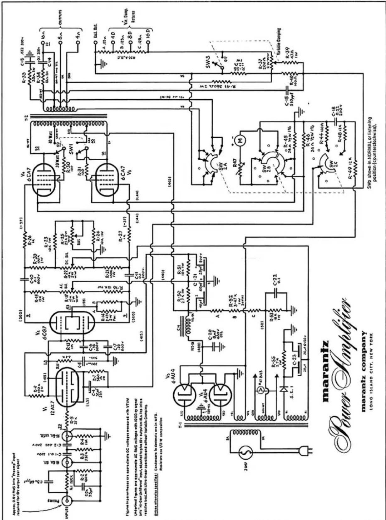
OPERATING DATA FOR THE MARANTZ POWER AMPLIFIER model 2
PRELIMINARY
The perforated protective grille is held in place by four spring clamps. It can be removed most easily with a light outward pull on it's bottom edges. Do not attempt to pry along top or sides with tools or damage to the finish may result. Remove all protective packing around the tubes and replace grille after carefully positioning flush with top and sides. A little pressure will snap it back into place.
Input and output cables may be attached and dressed down the front and under the amplifier where it can then be led out the back. The grille will then hide all wires, tubes, etc.
OPERATING LINE VOLTAGE:
117 Volts, 60 cycles (for A.C. operation only). All specifications are based on this voltage. The usable range is from 105 to 125 volts, 50-60 cycles.
INPUT CONNECTIONS:
There is a choice of three input connections to the Marantz Power amplifier;
1.- PREAMP- This input is recommended for most preamplifiers. At this connection a 2 volt signal will drive the amplifier to it's full output. A subsonic filter rolls off frequencies below 20 cycles so as to suppress speaker "breathing" and other subsonic disturbances.
2.- HIGH GAIN, FILTERED- For preamplifiers that have a low output voltage capability. Also may be used where loudspeaker has very low efficiency. A signal of 0.7 volts is required here for full 40 watt output. Subsonic filtering is also in effect.
3.- HIGH GAIN, UNFILTERED- Same as above in sensitivity but without the subsonic filter, response being maintained to below 2 cycles. This input is direct to the input grid and is used in testing frequency response or for special applications where subsonic response is needed.
OUTPUT CONNECTIONS:
When not using Variable Damping:
1.- Use "Ground Return" (center terminal) on loud speaker output terminal strip together with impedance tap on right which matches speaker.
2.- Variable Damping control must be switched off for proper operation.
To Use Variable Damping:
1.- Instead of usual ground return, connect to corresponding "Variable Damping Return". For Example: An 8 ohm speaker will have one lead on the 8ohm tap to right and the other on DS tap to the left. 2.- Turn "Variable Damping" control on and adjust to desired damping factor.
40 WATT-20 WATT SWITCH:
This unit has been designed primarily as a 40 watt Ultralinear Amplifier. Speaker systems of a lower power rating could easily be damaged by unwanted pulses coming through at full power. To protect these systems we have incorporated a switch
which changes the output connections to Triode operation limiting the power output to 22 or 23 Watts. This control, located near the output terminal strip, is marked "40 Watt UL" and "20 Watt TRI".
METERED TESTS and ADJUSTMENTS:
Each Amplifier is carefully adjusted at the factory for proper operation. Nevertheless the owner should check the operating conditions after 15 minutes when first placed in service and again after the tubes have "aged" perhaps 12 hours. Recheck every few months.
The test and adjustment section of the amplifier comprises the following:
1.- An accurate d'Arsonval type meter calibrated on the left for both the AC and the DC balances and again on the right to indicate the proper 120 milliampere BIAS condition.
2.- Three screwdriver adjustments marked AC BALANCE, DC BALANCE and BIAS. Grouped around the meter, they are protected from accidental shifting of calibration by black plastic screw-on caps. These should be removed before warming up for test to avoid burning hands on hot tubes.
3.- A test switch having four positions marked: NORMAL (playing position), BIAS, D.C. BALANCE and A.C. BALANCE. The latter three are the test positions corresponding to the meter readings and adjustments listed in 1 & 2 above.
TEST PROCEDURE: (Before making these tests be sure to turn the volume control fully down on the signal source connected to the amplifier.)
1.- Turn Test Switch to the BIAS test position. The meter pointer will swing to the right. Turn the Bias adjustment carefully with a screwdriver until the meter reading is on the BIAS-120 ma mark. (This reading will normally vary slightly during use with the line voltage and with warmup. In installation the BIAS may have to be reset. A current setting in excess of 120 ma will tend to decrease tube life.)
2.- Switching to the next test position, marked D.C. BALANCE, proceed as before, turning the D.C. BALANCE Adjustment until the needle is centered over the "BALANCE" or zero mark on the left of the meter dial face.
3.- The A.C. BALANCE position on the test switch has a spring return so that it will not accidentally be left in this position for any period of time. Holding the knob to this position a few seconds at a time turn the A.C. BALANCE Adjustment so that the needle again is centered over the Balance-Zero mark. In this test the needle will be seen to vibrate gently but it will not be difficult to read the correct position.
The Amplifier is now correctly adjusted and the test Switch should be returned to the NORMAL or playing position. Be sure to replace the protective plastic adjustment caps so that the amplifier will not be accidentally thrown out of calibration.
Marantz Company, 25-14 Broadway, Long Island City 6, N. Y.