Model 2330-B - Empfänger MARANTZ - Kostenlose Bedienungsanleitung
Finden Sie kostenlos die Bedienungsanleitung des Geräts Model 2330-B MARANTZ als PDF.

| Produkttyp | Stereo-Receiver |
| Marke | Marantz |
| Modell | 2330-B |
| Abmessungen (B x H x T) | 432 x 140 x 305 mm |
| Gewicht | 9,1 kg |
| Stromversorgung | 230 V, 50 Hz, 200 W |
| Ausgangsleistung (RMS) | 2 x 30 W an 8 Ohm |
| Frequenzbereich | 20 Hz - 20 kHz |
| Klirrfaktor | < 0,3 % |
| Signal-Rausch-Abstand | > 70 dB |
| Eingänge | Phono, AUX, Tuner, Tape 1, Tape 2 |
| Ausgänge | Lautsprecher A/B, Kopfhörer |
| UKW-Empfang | 87,5 - 108 MHz |
| MW-Empfang | 530 - 1600 kHz |
| Reinigung | Gehäuse mit trockenem Tuch abwischen; keine chemischen Reiniger |
| Sicherheit | Netzstecker ziehen vor Reinigung; nicht öffnen; nur vom Fachmann reparieren lassen |
| Ersatzteile und Reparatur | Ersatzteile über autorisierte Marantz-Händler; Reparatur durch qualifizierte Techniker |
Häufig gestellte Fragen - Model 2330-B MARANTZ
Benutzerfragen zu Model 2330-B MARANTZ
0 Frage zu diesem Gerät. Beantworten Sie die, die Sie kennen, oder stellen Sie Ihre eigene.
Eine neue Frage zu diesem Gerät stellen
Laden Sie die Anleitung für Ihr Empfänger kostenlos im PDF-Format! Finden Sie Ihr Handbuch Model 2330-B - MARANTZ und nehmen Sie Ihr elektronisches Gerät wieder in die Hand. Auf dieser Seite sind alle Dokumente veröffentlicht, die für die Verwendung Ihres Geräts notwendig sind. Model 2330-B von der Marke MARANTZ.
BEDIENUNGSANLEITUNG Model 2330-B MARANTZ
FOREWORD
To obtain maximum performance and enjoyment from the Model 2330B Stereo Receiver, please study these instructions carefully. Installing and operating the Model 2330B is not complicated, but the flexibility provided by its numerous operating features merits your becoming familiar with its controls and connections. Our recommended procedures will assure you of securing the superb performance for which the Model 2330B was designed.
For convenience, this manual is divided into two parts. The first part covers installation and operation in a simple, nontechnical manner. The second part provides a more detailed description of the features of the Model 2330B.
For quick identification of the many controls, connection facilities, and adjustments on the Model 2330B Stereo Receiver, all references to them in this manual are printed in BOLDFACE type.
GENERAL DESCRIPTION
The Marantz Model 2330B is an all solid state receiver incorporating the innovative design and unparalleled technology that have made Marantz famous in the audio component industry.
The Model 2330B features a sensitive FM tuner, a highly selective AM tuner, a low distortion preamplifier, and two direct coupled power amplifiers on a single chassis, while retaining a flexibility comparable to that achieved using separate components. The FM tuner utilizes an MOSFET front end, ceramic IF filters, and an advanced integrated circuit for high selectivity and sensitivity.
The amplifier sections permit the connection of two stereo pairs of loudspeakers, two turntables or record changers, two tape recorders, stereo headphones, and an auxiliary source such as an additional tuner or a TV sound source. The 2330B also features a variable turnover tone control and front panel dubbing jacks.
AFTER UNPACKING
It will be to your advantage to save all the packing materials, carton, fillers, cushioning, etc. They will prove valuable in preventing damage should it become necessary to transport or ship the Model 2330B. Be careful that you do not inadvertently throw away or lose the parts packed with the unit.
Please inspect this unit carefully for any signs of damage incurred in transit. It has undergone very strict quality control inspections and tests prior to packing, and it left the factory unmarred and in perfect operating condition. If the unit was shipped directly to you and you discover damage, notify the transportation company without delay. Only you, the consignee, may institute a claim against the carrier for damage during shipment. However, the Marantz Company will cooperate fully with you in such an event. Save the carton as evidence of damage for their inspection. If you received the unit directly from a Marantz dealer, return it to him for adjustment.
TABLE OF CONTENTS
Preparation for Use 3
Mechanical Installation 3
Marantz Walnut Wood Veneer Cabinet 3
Custom Installation 3
Connecting the Model 2330B 3
Phono Inputs Jacks 3
Tape Monitor Jacks 4
Aux Input Jacks 4
FM Antenna 4
Outdoor FM Antennas 4
AM Antenna 5
Pre Out and Main In Jacks 5
Speaker Systems 5
Speaker Phasing 6
Connection to AC Outlet 7
Convenience Outlets 7
AC Protector Fuse 7
Dolby Plug-in FM Decoder Installation 7
Signal Connection Checklist 7
Simplified Operating Procedures 8
Main Controls and Switches 8
Power Switch 8
Selector Switch 8
Volume Control 8
Balance Control 8
Bass, Mid and Treble Controls 8
Tone Mode Switch 9
Mode Switch 9
Tuning Meters 9
Gyro-Touch Tuning Knob 9
Multipath Button 9
MPX Noise Filter Switch 10
Filters Switches 10
Loudness Switch 10
FM Muting Switch and Muting Level
Control 10
Speaker System Switches 11
Phones Jack 11
Tape Monitor Switches, Tape Copy
Switches and Dubbing Jacks 11
Using Tape Recorders with Your Model 2330B 11
Dubbing Jacks 11
Tape Monitoring 12
Making Tape Recordings 12
How to Make Tape-to-Tape Copies 13
Making Modified Tape Recordings 13
Dolby FM Process 14
Dolby FM Reception 14
Recording Dolbyized FM Programs 15
Technical Description 17
General 17
FM Tuner Section 17
Front End 17
IF Amplifier 17
Multipath Indicator 17
Stereo Demodulator 17
Muting Circuit 17
AM Tuner Section 17
Amplifier Section 18
Selector Switch 18
Phono Amplifier 18
MPX Noise Filter 18
Balance Control 18
Volume Control 18
Tone Circuit 19
Output Stage and Protective Circuits 19
Service Notes 20
Fuse Replacement 20
Cleaning 20
In Case of Difficulty 20
Repairs 20
Repacking for Shipment 21
LIST OF ILLUSTRATIONS
-
Rear Panel Connection Facilities and Adjustments 3
-
FM Antenna Connection 4
-
AM Ferrite-rod Antenna 5
-
Speaker System Connections 6
-
Front Panel Controls and Jacks 8
-
Three Conductor Phone Plug 10
-
Patch Cord for Dubbing 11
-
Typical Tape Recorder Connections 12
-
Arrangement for Making Modified Tape Copies 13
-
Functional Block Diagram 16
-
Tone Control Characteristics 18
-
15 Hz and 9 kHz Filter Characteristics 19
-
Packing Instructions 21

text_image
SPEAKER SYSTEMS SYSTEM 1 SYSTEM 2 MUTING LEVEL MIN MAX ANTENNA FM 780 FM [3000]~780~ AM 2350A RECEPTACLE AQ OUTS ETS 100W MAX UNSWITCHED SWITCHED 200W MAX 100W MAX MAIN PRE TAPE MONITOR IN OUT IN OUT OUT IN IN OUT IN IN OUT IN IN OUT IN IN OUT IN IN OUT IN IN OUT IN IN OUT IN IN OUT IN IN OUT IN IN OUT IN IN OUT IN IN OUT IN IN OUT IN IN OUT IN IN OUT IN IN OUT IN IN OUT IN IN OUT IN IN OUT IN IN OUT IN IN OUT IN IN OUT IN IN OUT IN IN OUT IN IN OUT IN I L M P S R T R CHARGED COUNDEDFigure 1. Rear Panel Connection Facilities and Adjustments
PREPARATION FOR USE
MECHANICAL INSTALLATION
The Model 2330B Stereo Receiver can be installed in two basic ways: In a beautiful walnut cabinet for placement on a table or shelf, or mounted in your own cabinetry or custom installation.
MARANTZ WALNUT WOOD VENEER CABINET
An optional walnut wood veneer cabinet, Model WC-123, may be obtained from your Marantz dealer. The case provides for proper ventilation, and can be placed on furniture, or on a bookshelf. Complete instructions for installation are provided with the WC-123.
CUSTOM INSTALLATION
When planning a custom installation, allow adequate spacing between the Model 2330B, cabinet surfaces, and other components for adequate ventilation.
To install the Model 2330B Stereo Receiver in a custom cabinet, cut an opening 19 inches wide by 5-3/8 inches high. Since the front panel of the Model 2330B is larger than the cutout, it will neatly hide the edges of the cut. Remove the plastic feet from the bottom of the unit and slide it through the opening. To support the weight of the Model 2330B, adequate bracing across the rear of the cabinet must be located to provide contact with the rear of the unit.
CONNECTING THE MODEL 2330B
Figure 1 shows the location of input and output jacks on the rear panel. These jacks are for "permanent" connections. Front panel jacks and their use will be discussed later. All connections to the rear panel should be made with the power to the entire system turned off. The rear panel signal connections are arranged in stereo pairs. All signal connections to the Model 2330B, with the exception of the FM antenna and loudspeakers, should be made with shielded audio cables. To avoid confusion, connect one cable at a time between the 2330B and the other components of your system. This is the safest way to avoid cross-connecting channels or confusing signal source outputs with inputs.
PHONO INPUTS JACKS
The PHONO jacks (1 and 2) are intended for use with magnetic phono cartridges and have a 47,000 ohm input impedance.
If a hum is heard when playing records, this is an indication that the record player or its connections are inadequately grounded. Connect a separate ground wire from the turntable or record changer frame to the CHASSIS GROUND binding post of the Model 2330B. If this is ineffective, try reversing the polarity of the turntable's power plug.
If hum persists, consult the instruction booklets for the turntable and/or phono cartridge.
TAPE MONITOR JACKS
The rear panel of the 2330B can accommodate two tape recorders.
The terms IN and OUT refer to the input and output of the Model 2330B. Therefore, the IN jacks on the Model 2330B accept signals from the line outputs of each tape recorder; the OUT jacks feed signal to the tape recorders' line inputs.
AUX INPUT JACKS
The AUX INPUTS jacks are for miscellaneous high level signal sources such as additional tuners and/or receivers, tape players, phonographs that provide RIAA equalized high level output, TV sound outputs and other external components.
FM ANTENNA
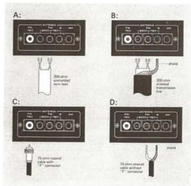
Included in the accessory kit is a ribbon-type "folded dipole" FM antenna. This type of antenna is simple and practical and will give adequate results in primary signal areas. To use it, unfold it into a "T" shape and connect its leads to the terminals marked "300 Ω" on the back of the receiver (See Figure 2A). The antenna is designed to operate in a horizontal position. Temporarily (for the purpose of getting started) attach it to a nearby wall.
As shown in Figure 2, the Model 2330B is also capable of accommodating other types of cable, including 75-ohm coaxial cable (with or without "F"-type connector), and 300-ohm shielded transmission line. These types of cable are for use with outdoor antennas, which will be discussed next.
OUTDOOR FM ANTENNAS
As stated before, the supplied folded dipole antenna will give satisfactory results in primary signal areas. It should be obvious, however, that if you are located in a fringe area where signals are weak, then an outdoor antenna will be necessary. Even if you live in a strong signal location, an outdoor directional antenna may be needed to eliminate "multipath" reflections.
Multipath reflections are responsible for much of the distortion and sibilance associated with poor FM reception. They occur when radio waves from the transmitter bounce off of nearby mountains and tall buildings. The reflected waves follow different, more roundabout paths to your tuner and arrive slightly delayed and out of phase with the direct signal (hence, the term "multipath"). This causes distortion in the same manner that "ghost" images are generated on television.
The way to minimize multipath is to use a "beam type" antenna that can be aimed toward the FM transmitter and away from the multipath reflections. The best types of antennas to use are either a "Yagi" or "Log-Periodic" configuration with six or more elements designed expressly for FM reception.
If you want to receive stations from more than one general direction, then you will need a good quality antenna rotor system. This will enable you to point the antenna in the direction giving the least multipath interference, by means of a control box located near the receiver.
Another important factor is the type of lead-in wire to use. Unshielded lead-in wires, such as 300-ohm twin lead, can act as an omnidirectional antenna, and can cancel the directional benefits of your antenna. Therefore, we recommend using a balanced, shielded 300-ohm cable or a coaxial 75-ohm cable with a 300-to-75-ohm matching transformer at the antenna. These types of shielded cable effectively prevent the lead-in from contributing to multipath distortion.
Shielded antenna cable will be available at the same store where you buy your antenna. If you decide to use 75-ohm coaxial cable, we recommend buying cable with "F"-type connectors attached. These will fit both the matching transformer and the terminal on the Model 2330B (See Figure 2C).
text_image
A: F10 FB5 300 ohm unshielded Tens lead B: F10 FB5 300 ohm unshielded transmission line C: F10 FB5 300 ohm unshielded Tens lead D: F10 FB5 300 ohm unshielded Tens lead 75 ohm coaxial cable with "F" connector 75 ohm coaxial cable without "F" connectorFigure 2. FM Antenna Connection
It is considered good practice to connect the antenna mast to an earth ground, both for reasons of safety and noise reduction. If 300-ohm shielded cable is used, connect the shield to ground (G) at the receiver end only.
For rural areas, it is recommended to consult a local dealer about installation and lightning arrestor protection.
We don't recommend using master antenna systems, such as those found in apartment buildings. Such systems are usually designed expressly for television reception and frequently suppress or reduce the quality of the FM signals before distribution.
Where outdoor antennas are prohibited or inconvenient, the simplest form of "rabbit-ear" TV antenna is the most practical and will give satisfactory results. This type is preferred over the folded dipole because it can be more readily rotated for the best reception.
AM ANTENNA
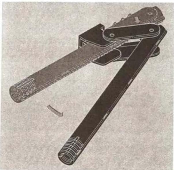
Your Receiver is equipped with an AM ferrite-rod antenna. BEFORE USING THE MODEL 2330B, SWING THE ANTENNA OUT AS SHOWN IN FIGURE 3.
The ferrite-rod antenna will give you satisfactory results in primary signal areas. However, an outdoor antenna will provide better reception in weaker signal areas. Two single wires are required to make an AM outdoor antenna. First, connect one end of a single wire to the AM ANTENNA
natural_image
Illustration of a mechanical tool with a cylindrical handle and metal bracket (no text or symbols visible)Figure 3. AM Ferrite-rod Antenna
terminal on the rear panel, and the other end to a very high horizontal antenna wire of 25 to 75 feet in length suspended between insulators in an outdoor location (the higher the better). Next, connect the other single wire between the "G" terminal of your Model 2330B and an authenticated earth ground (such as a metal water pipe).
PRE OUT AND MAIN IN JACKS
The PRE OUT jacks deliver the output of the Model 2330B preamplifier circuits to the rear panel.
The MAIN IN jacks are the input terminals of the power amplifier section of the Model 2330B. The PRE OUT and MAIN IN jacks are bridged internally by special contacts within the jack assembly. When you wish to use such equipment as a graphic equalizer, compressor/limiter, or expander, you may connect these instruments to your Model 2330B with appropriate length of shielded audio cables. When the external equipment is connected, the insertion of its RCA phono plugs into the MAIN IN jacks automatically breaks the internal connections to prevent the external equipment from being bypassed.
SPEAKER SYSTEMS
The SPEAKER SYSTEMS terminals on the rear panel can accommodate two stereo pairs of loudspeakers. Connect the main pair to the SYSTEM 1 terminals. The SYSTEM 2 terminals are for a second stereo pair of loudspeakers (see Figure 4). Selection of loudspeaker systems is made with the SPEAKERS pushswitches on the front panel.
NOTE: Do not use 4 ohm speakers if system 1 and system 2 speakers are to be used simultaneously. Use 8 or 16 ohm speakers only.
SPEAKER PHASING
To assure the best stereo separation and frequency response, the speakers must be properly phased. The positive terminal on each speaker should be connected to its respective (+) terminal on the Model 2330B, and the negative or "common" terminal should be connected to its respective (−) terminal. To verify that a pair of speakers are correctly phased, perform the following test:
- Complete the necessary signal connections so that program material may be played through the speakers.
-
Place the speakers in the center of the room.
-
Set the MODE switch to L + R and play a record (or radio or tape) with strong bass tones at a low volume level. Set the BALANCE control to the 12 o'clock position.
- Position the speakers about six inches apart, face-to-face. Listen, particularly to the apparent loudness of the bass tones.
- Next, turn off all power, but do not disturb the VOLUME or BALANCE settings. Reverse the connections on the right speaker only. Turn on the power and listen again. If the bass tones now seem louder than in (4), you have corrected the phasing between the speakers. If the bass notes now sound softer, turn off the power and re-connect the speakers as they had been originally.

flowchart
graph TD
    A["SYSTEM 1 SPEAKER SYSTEMS"] --> B["Left"]
    A --> C["RIGHT"]
    D["SYSTEM 2 SPEAKER SYSTEMS"] --> E["LEFT"]
    D --> F["RIGHT"]
    B --> G["Device Layout 1"]
    C --> H["Device Layout 2"]
    style A fill:#f9f,stroke:#333
    style D fill:#f9f,stroke:#333
Figure 4. Speaker System Connections
- If an additional pair of speakers is used along with the system 1 speaker system, check phasing between the system 2 speakers and the system 1 speakers. Use the BALANCE control to play only two speakers at once, and invert the wiring on the system 2 speakers as necessary. Do not change the connections on the system 1 speaker system.
- Once having phased all speakers, you need not repeat this procedure in the future if you now mark the speaker connections and/or cables. Any method of coding is satisfactory, provided it enables you, in the future, to duplicate your now-correct, hookup between speakers and amplifier.
Use caution when connecting your Model 2330B to a loudspeaker with built-in power supply such as an electrostatic loudspeaker. The "common" connection terminal of such a speaker may be capacitively coupled to ground through its own power supply. To protect the Model 2330B from distortion and possible overload, make sure the (−) terminals of the Model 2330B are connected to the "common" terminals of such a loudspeaker system.
CAUTION: NEVER DIRECTLY CONNECT THE LOUDSPEAKER TERMINALS OF ONE CHANNEL IN PARALLEL WITH THOSE OF ANY OTHER. ANY RESULTING DAMAGE IS NOT COVERED UNDER WARRANTY.
CONNECTION TO AC OUTLET
With the front panel POWER pushswitch "OUT", plug the line cord into an electrical outlet supplying the proper voltage.
CAUTION: DO NOT PLUG YOUR MODEL 2330B INTO A DC OUTLET, AS SERIOUS DAMAGE WILL OCCUR.
CONVENIENCE OUTLETS
One UNSWITCHED and one SWITCHED AC OUTLETS are provided on the rear panel for powering associated components of your system (tape recorder, recorded player, etc.).
AC PROTECTOR FUSE
This feature automatically disconnects AC power in the event of a power source or circuit overload. If the POWER pushswitch is activated and the front panel fails to illuminate and no sound is heard through the speakers, unscrew the fuse holder on the rear panel and visually inspect the fuse to see if the internal conducting filament has opened. If so, replace the fuse with one having the same specifications.
DOLBY PLUG-IN FM DECODER INSTALLATION
The pocket on the rear panel will accommodate Marantz Model DLB-1 Plug-in FM Dolby Decoder. For use, follow the instructions supplied with the optional decoder. For more information, see "DOLBY FM RECEPTION", page 14.
SIGNAL CONNECTIONS CHECKLIST
Before proceeding with operation, double check to make sure the following preparations have been made.
- SPEAKERS connected to SPEAKER SYSTEMS terminals. Speaker wires are not shorted together.
- ANTENNA connected properly.
- AM FERRITE-ROD antenna extended.
- AC LINE CORD plugged in.
- PHONO, TAPE, and AUX plugs are pushed full into jacks.

text_image
Model 2530 L maser-matrix Therapeutic Receiver + AU + AU + MON1 + MON2 + N2 + NDC 88 90 92 94 96 98 100 102 104 106 108 SND SND SND SND SND SND SND SND SND SND SND SND SND SND SND SND SND SND SND SND SND SND SND SND SND SND SND SND SND SND SND SND SND SND SND SND SND SND SND SND SND SND SND SND SND SND SND SND SND SND SND dubbing selector mode tone mode bass mid treble balance volume phoneFigure 5. Front Panel Controls and Jacks
SIMPLIFIED OPERATING PROCEDURES
When operating the Model 2330B Stereo Receiver for the first time, follow these simple directions. Later, full advantage can be taken of its versatility with the remaining controls and pushswitches.
Step 1. Connect the FM antenna to the appropriate terminals on the rear panel.
Step 2. Connect the speakers to the SYSTEM 1 speaker terminals.
Step 3. Place all pushswitches in the "out" position.
Step 4. Turn the VOLUME control all the way to the left (counterclockwise) and set the BALANCE control to the 12 o'clock position.
Step 5. Rotate TREBLE, MID and BASS controls to the 12 o'clock position (each pair of pointers to dot).
Step 6. Depress the SYSTEM 1-SPEAKERS push-switch.
Step 7. Apply system power by depressing the POWER switch.
Step 8. Select the desired program source by setting the SELECTOR switch to the appropriate position. If FM, FM 25 μS or AM is selected, rotate the GYRO-TOUCH TUNING knob until the desired station is tuned. Adjust the VOLUME control to a comfortable listening level.
MAIN CONTROLS AND SWITCHES
POWER SWITCH
The POWER switch, when depressed, supplies AC power to the Model 2330B and to the SWITCHED outlet on its rear panel.
SELECTOR SWITCH
The SELECTOR switch selects the program source for listening or recording. For more information on the FM 25 μS position, refer to "DOLBY FM PROCESS" section, page 14.
VOLUME CONTROL
The VOLUME control adjusts the level of both output channels simultaneously while maintaining stereo balance at all normal settings. It does not effect the recording outputs.
BALANCE CONTROL
This control alters the level of either output channel in situations where it is necessary to correct unbalanced programs sometimes encountered in older stereo recordings or in stereo broadcasts. As it is moved from its center position, it decreases the level in one output channel while maintaining the level in the other channel.
BASS, MID, AND TREBLE CONTROLS
The three tone controls, BASS, MID, and TRE-BLE, adjust the normally "flat" frequency response of the Model 2330B to suit individual listening preference.
The BASS control adjusts the low frequency tones, the MID control adjusts the middle frequency tones, and the TREBLE control adjusts the high frequency tones.
These controls may be adjusted to compensate for unbalanced room acoustics or any other tonal difference between the left and right channels of the stereo program. The tone controls have no effect on the signals present at the TAPE MONITOR 1 OUT or TAPE MONITOR 2 OUT jacks.
TONE MODE SWITCH
The TONE MODE switch determines the operating characteristics of the BASS, MID and TREBLE controls, and allows additional flexibility in compensating for room, speaker, and program characteristics. The switch affects the tone controls as follows:
OUT: The tone controls are switched out of circuit, and frequency response is made flat regardless of their positions.
IN: The tone controls operate normally.
100 Hz: The turnover frequency of the BASS tone control is shifted from 400 Hz to 100 Hz, while the MID and TREBLE operate normally.
10 KHz: The turnover frequency of the TREBLE tone control is shifted from 3 kHz to 10 kHz, while the BASS and MID operate normally.
100 Hz/10 KHz: Both BASS and TREBLE are affected as above, while MID operates normally.
MODE SWITCH
This switch is a five position rotary switch that provides the following signal functions:
REVERSE: The LEFT and RIGHT channel signals are reversely routed to drive the RIGHT and LEFT audio channel speakers, respectively.
STEREO: The LEFT channel signal is routed to drive the left audio channel speaker, and the RIGHT channel is routed to drive the right audio channel speaker.
L + R: The LEFT and RIGHT channel signals are mixed and routed to drive both right and left audio channel speakers.
L: The LEFT channel signal is routed to drive both right and left audio channel speakers.
R: The RIGHT channel signal is routed to drive both right and left audio channel speakers.
When playing a single channel source such as TV, set the switch to either L or R position or to L + R so that the single channel source can be heard through both speakers.
TUNING METERS
The Model 2330B is equipped with two meters, a SIGNAL STRENGTH meter and an FM TUNING meter.
-
The SIGNAL STRENGTH meter indicates the relative signal strength of any AM or FM broadcast. It also functions as a MULTIPATH meter when the MULTIPATH button is pushed.
-
The FM TUNING meter operates only when FM is selected and indicates correct station tuning when centered.
GYRO-TOUCH TUNING KNOB
AM: Switch the SELECTOR to AM and tune to the desired station. Then rotate the GYRO-TOUCH TUNING knob slightly back and forth until the maximum reading is obtained on the SIGNAL STRENGTH meter.
FM: Switch the SELECTOR to FM and tune to the desired station. Then rotate the GYRO-TOUCH TUNING knob slightly back and forth until the maximum reading is obtained on the SIGNAL STRENGTH meter and a center scale reading is obtained on the FM TUNING meter.
MULTIPATH BUTTON
When using a rotatable FM antenna, FM reception may be further optimized by pointing the antenna in the proper direction for minimum multipath.
First, tune to the desired station as above. Then, hold in the MULTIPATH button while rotating the FM antenna. Stop the antenna at the position for which a minimum deflection is indicated on the MULTIPATH meter. Then, release the MULTIPATH button to restore the meter to its normal SIGNAL STRENGTH function.
MPX NOISE FILTER SWITCH
The MPX NOISE FILTER function is useful for reducing noise on weak stereo FM signals with excessive noise and/or interference. When activated, the MPX NOISE FILTER slightly reduces separation at high audio frequencies. This offers moderate separation along with considerable suppression of out-of-phase noise and distortion components. Unlike most noise filters, the MPX NOISE FILTER does not sacrifice full frequency response.
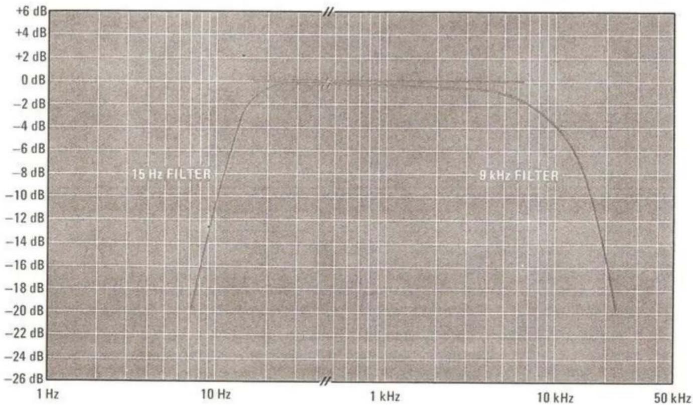
FILTERS SWITCHES
Two FILTERS switches permit suppressing low- or high-frequency noise that may originate at the program source.
The 15 Hz FILTER pushswitch activates a low frequency filter which reduces signal levels below 15 Hz. The filter has little or no adverse effect on the system's overall frequency response, because frequencies of 15 Hz and lower are below the range of most program material.
The filter will, however, substantially improve system performance when you play phonograph records at a high volume level. A high quality phono cartridge will faithfully reproduce turntable rumble, record cutting lathe rumble, and even the slight warp of a new record in the form of a low frequency (0.5 Hz to 10 Hz) noise. If this noise is allowed to pass through the preamp and amplifier, it may cause excessively large excursions of the woofer cones. These speaker excursions (pulsations) can result in high intermodulation distortion throughout the bass and lower midrange of the program material, and contribute to the overheating and possible failure of the woofers. An unnecessarily high proportion of amplifier power is wasted reproducing these low frequency noise components. Activating the 15 Hz FILTER prevents this from happening, and allows more power to be made available for the important program frequency range.
When the 9 KHz FILTER switch is depressed, high frequency noise, such as the hiss associated with noisy FM, poorly recorded tapes, or scratchy phonograph records, will be reduced sharply. The 9 KHz FILTER should only be used during extremely noisy conditions, because it reduces high frequency response appreciably.
LOUDNESS SWITCH
The LOUDNESS switch compensates for human hearing characteristics by boosting the bass and treble response at low volume levels to achieve a more pleasing tonal balance.
FM MUTING SWITCH AND MUTING LEVEL CONTROL
In the absence of an FM carrier, all FM receivers produce noise. This noise is apparent between stations while tuning.
The FM MUTING pushswitch activates circuitry features in the Model 2330B which mutes the audio outputs when tuned "off-station".
The MUTING LEVEL control on the rear panel determines the threshold level for the muting circuitry. Maximum muting effect is achieved by setting the MUTING LEVEL to MAX. To prevent muting very weak stations along with the noise, the muting function may be turned off by releasing the FM MUTING pushswitch.
text_image
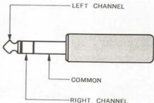
LEFT CHANNEL COMMON RIGHT CHANNELFigure 6. Three Conductor Phone Plug
SPEAKER SYSTEM SWITCHES
These switches select the loudspeaker terminals to which audio power is fed. Either the system 1 or the system 2 stereo pair of loudspeakers may be operated individually, or simultaneously if both switches are depressed. When the two SPEAKERS switches are in the normal "out" position, all loudspeaker terminals are internally disconnected from the power amplifier section. The signals at the headphones jack and recording outputs are not affected by the SPEAKERS switches. The "out" position allows "private listening" when stereo headphones are used.
NOTE: Volume level should be reduced to minimum when switching speakers.
PHONES JACK
This jack accepts headphones utilizing a standard three conductor phone plug (see Figure 6). It is internally connected to the power amplifier section through isolation resistors to provide adequate sound level with popular low impedance headphones as well as with high impedance units. Two or more sets of headphones may be used with the aid of "T" connectors. However, output level will drop as additional headphones are added. The headphone jack output is not affected by the SPEAKERS switches.
TAPE MONITOR SWITCHES, TAPE COPY SWITCHES AND DUBBING JACKS
See the following section on tape recorders.
USING TAPE RECORDERS WITH YOUR MODEL 2330B
The Model 2330B provides three sets of inputs and outputs for tape recorders: TAPE MONITOR 1, TAPE MONITOR 2, and DUBBING (IN and OUT). To simplify this discussion, the tape recorder connected to the TAPE MONITOR 1 jacks will be referred to as the "MAIN" recorder; the tape recorder connected to TAPE MONITOR 2 will be referred to as "SECONDARY" recorder; the recorder connected to the DUBBING facilities on the front panel will be referred to as the "EXTERNAL" recorder.
DUBBING JACKS
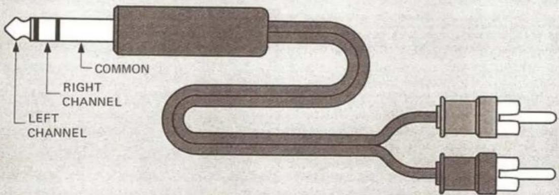
The DUBBING IN jack is the front panel equivalent to the rear panel TAPE MONITOR 2 IN jacks. To connect an "EXTERNAL" tape recorder, it is necessary to use a patch cord having a standard three-conductor stereo phone plug on one end and two RCA phono-type plugs on the other (Figure 7). Such a patch cord is available at your Marantz dealer. Connect the patch cord from the tape recorder line outputs to the Model 2330B DUBBING IN jack as shown in Figure 8. When the stereo phone plug is inserted into the DUBBING IN jack, the "EXTERNAL" tape recorder pre-empts the "SECONDARY" tape recorder by automatically disconnecting the rear panel TAPE MONITOR 2 IN jacks.
text_image
COMMON RIGHT CHANNEL LEFT CHANNELFigure 7. Patch Cord for Dubbing
The DUBBING OUT jack is the front panel equivalent to the rear panel TAPE MONITOR 2 OUT jacks and is permanently connected in parallel with the TAPE MONITOR 2 OUT jacks. Therefore, any source material available at the rear panel output jacks except that from the TAPE MONITOR 2 IN (when DUBBING IN is connected), is simultaneously available at the DUBBING OUT jack. The line inputs of the "EXTERNAL" tape recorder are connected to the DUBBING OUT jack using the same type of patch cord described in the preceding paragraph.
TAPE MONITORING
The TAPE MONITOR switches operate independently of the SELECTOR and TAPE COPY switches. If both TAPE MONITOR switches are depressed simultaneously, "MAIN" recorder takes priority of "SECONDARY" recorder. Thus any tape recorder can be monitored regardless of which input is chosen. Monitoring of any of the tape recorders may be accomplished as follows:
"MAIN" recorder—Depress the TAPE MONITOR 1 switch.
"SECONDARY" recorder—Depress the TAPE MONITOR 2 switch.
"EXTERNAL" recorder—With the "EXTERNAL" recorder connected to the DUBBING IN jack, depress the TAPE MONITOR 2 switch.
To cue up the tapes for copying, to set recording levels, or to check the progress of the copying operation, depress the TAPE MONITOR 1 or 2 switch.
To listen to a different program (such as a tuner or phonograph) during the time a tape is being copied, release the TAPE MONITOR switch. Select the source material by means of the SELECTOR switch and play it as usual.
MAKING TAPE RECORDINGS
The SELECTOR switch determines the source input for tape recording. When PHONO 1, PHONO 2, AM, FM, FM 25 μS, or AUX are chosen, the source input can be recorded onto the "MAIN", "SECONDARY", and "EXTERNAL" tape recorders individually or simultaneously. See Figure 8 for typical tape recorder connections.

flowchart
graph TD
    A["SECONDARY RECORDER"] -->|R OUT L R IN| B["FRONT PANEL"]
    C["MAIN RECORDER"] -->|OUT L R IN| B
    B --> D["REAR PANEL"]
    D --> E["OUT L R IN"]
    F["EXTERNAL RECORDER"] -->|OUT R L R IN| D
Figure 8. Typical Tape Recorder Connections
HOW TO MAKE TAPE-TO-TAPE COPIES
The tape copying feature on the Model 2330B functions independently of the SELECTOR and TAPE MONITOR switches. This means that tapes can be copied while listening to an entirely different program source. Operation is as follows:
To make a dub (tape copy) from the "MAIN" recorder onto the "SECONDARY" and/or "EXTERNAL" recorders, depress the TAPE COPY 1→2 switch. The "MAIN" tape recorder then becomes the tape copy source. When this is the case, the TAPE MONITOR 1 OUT jacks are muted to prevent feedback oscillations that would occur if the "MAIN" recorder were inadvertently placed in the record mode.
To make a dub from the "SECONDARY" or "EXTERNAL" recorder onto the "MAIN" recorder, depress the TAPE COPY 2→1 switch. The "SECONDARY" recorder then becomes the tape copy source.
If the "EXTERNAL" tape recorder is connected to the DUBBING IN jack, then it pre-empts the "SECONDARY" recorder and becomes the tape copy source instead. The TAPE MONITOR 2 OUT and DUBBING OUT jacks are muted to prevent feedback oscillations. Therefore, dubs to the "MAIN" recorder may only be made from one of these two recorders at a time.
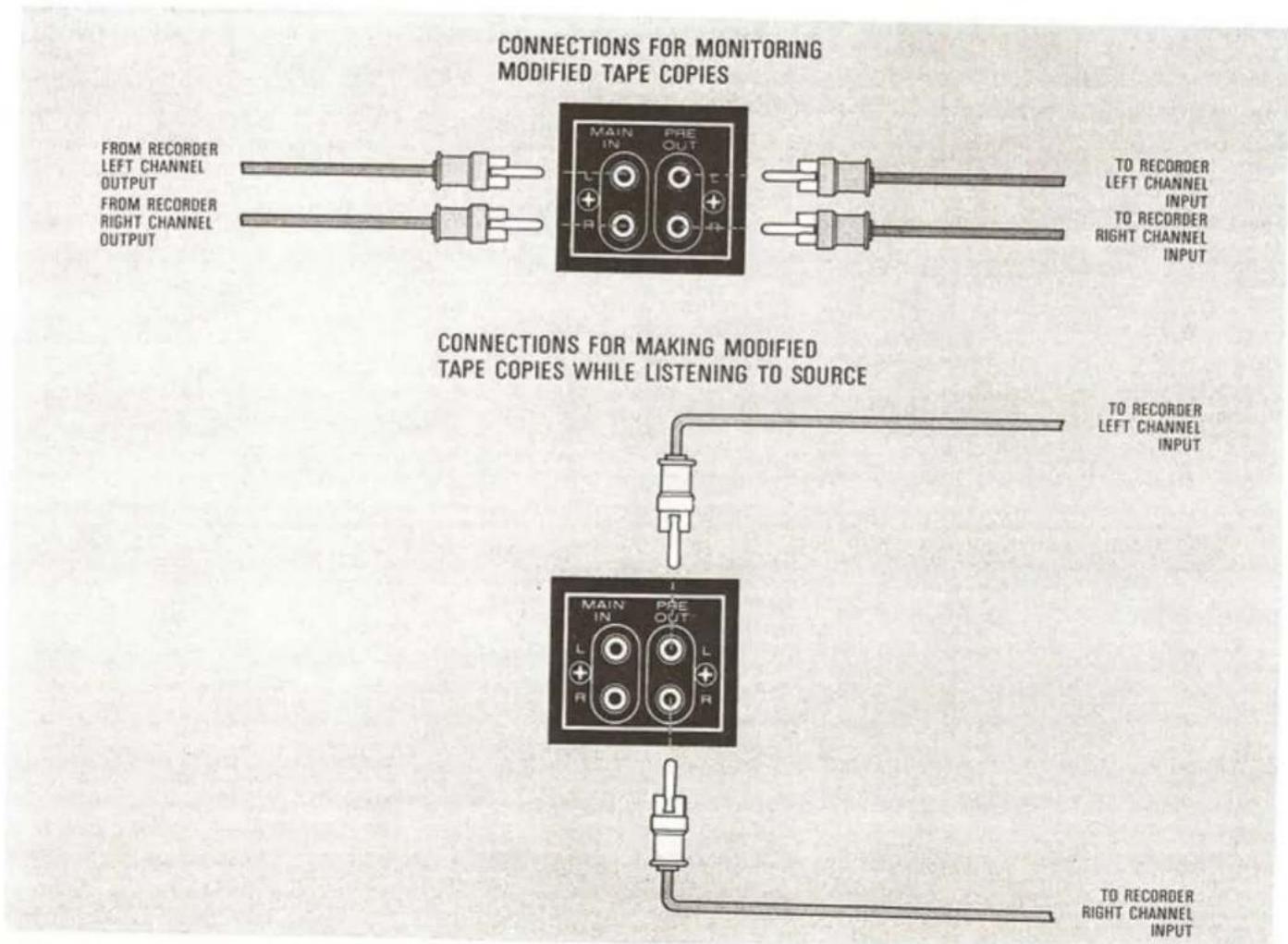
MAKING MODIFIED TAPE RECORDINGS
The PRE OUT jacks on the rear panel of the 2330B may be used to feed input signals to a tape recorder so that filters, balance, and tone controls can be used to modify the signal prior to recording. When using this method, leave the TAPE MONITOR switches released.
Modified tape copies can likewise be made. First, select the tape to be used as a source on the TAPE MONITOR switches. Next, connect the input of the second tape recorder to the PRE OUT jacks. By connecting the output of the
flowchart
graph TD
    A["FORM RECORDER\nLEFT CHANNEL\nOUTPUT\nFROM RECORDER\nRIGHT CHANNEL\nOUTPUT"] --> B["MAIN IN PRE OUT"]
    B --> C["TO RECORDER\nLEFT CHANNEL\nINPUT\nTO RECORDER\nRIGHT CHANNEL\nINPUT"]
    D["CONNECTIONS FOR MAKING MODIFIED TAPE COPIES WHILE LISTENING TO SOURCE"] --> E["TO RECORDER\nLEFT CHANNEL\nINPUT"]
    F["CONNECTIONS FOR MONITORING MODIFIED TAPE COPIES"] --> G["MAIN IN PRE OUT"]
    G --> H["TO RECORDER\nRIGHT CHANNEL\nINPUT"]
Figure 9. Arrangement for Making Modified Tape Copies
second tape recorder directly to the MAIN IN jacks, the newly recorded tape can be monitored. However, please note that when this method is employed, the volume level of the speakers is determined only by the output level of the tape recorder. Adjustment of volume is possible only if the recorder has output level controls.
DOLBY FM PROCESS
DOLBY FM RECEPTION
The Dolby System is an electronic method of reducing the amount of background noise ("tape hiss") inherent in tape recording. The same noise reduction technology is being applied by a growing number of FM radio stations to improve the signal-to-noise ratio of their broadcast signals.
In the case of tape recording, mid- and high-frequency audio signals are increased in level during soft volume passages in the recording and decreased by an identical amount during play-back. As a result, the playback signal is identical to the original source signal, but the level of background noise generated by the tape recorder is greatly reduced.
In the case of Dolby FM broadcasting, the FM broadcast is subjected to the first phase of the Dolby process before being transmitted. When these signals are received by the tuner and passed through a Dolby playback processor, the amount of FM hiss is reduced in the same way as with a tape recorder.
To further improve the noise reduction process, the FM station broadcasting in Dolby applies a special "pre-emphasis" to the frequency response of the music. When receiving these broadcasts, it is necessary to apply the proper "de-emphasis" to return the frequency response to normal.
The FM 25 μS position on the SELECTOR switch serves two functions. First, it supplies the proper de-emphasis mentioned above. Second, it internally presets the audio output signal to the standard Dolby level (580 mV) and applies this signal to the TAPE MONITOR OUT jacks and the DOLBY FM DECODER RECEPTACLE on the rear panel.
The DOLBY FM DECODER RECEPTACLE is designed to accept the optional Marantz Model DLB-1 Dolby FM decoder, which is available at your Marantz dealer. When the adaptor is plugged in and the SELECTOR switch is placed in the FM 25 μS position, the DLB-1 is automatically placed in circuit to de-process the Dolby-encoded FM broadcast. Additionally, the DLB-1 indicator on the front panel will illuminate and the signals at the TAPE MONITOR OUT jacks will also be de-processed.
If your audio system already contains a Marantz Dolby-equipped cassette deck (such as Model
5420, 5220, 5120 or 5020) or an outboard Dolby unit, then the DLB-1 Dolby FM Decoder is not required. Instead, you may use the Dolby System in one of these other components.
For use with our cassette decks, refer to the instructions included with them. Place the SELECTOR switch on the Model 2330B in the FM 25 μS position to supply the proper de-emphasis and output level at the TAPE MONITOR OUT jacks.
For use with an outboard Dolby unit, connect the playback portion of the Dolby unit to the output of the tuner, either by way of the tape monitor circuitry or by re-connecting the cables on the various units. The Dolby unit should be calibrated to the proper level by using the Dolby reference tone transmitted by the FM station at the beginning of the broadcast.
RECORDING DOLBYIZED FM PROGRAMS
If your audio system contains a reel-to-reel or cassette tape deck with a Dolby Noise Reduction System, you may wish to make a recording of a Dolbyized FM broadcast and then play the program back later through your Dolby System, thus reducing tape hiss and FM hiss at the same time.
Since Dolbyized FM programs use a noise reduction technique identical to Dolbyized tape recording, it is possible to record the Dolby-encoded signal directly off the air and onto your tape recorder.
If you are using an outboard Dolby unit, and you wish to make a Dolbyized tape recording of such a broadcast, switch the SELECTOR to the FM 25 μS position to properly de-emphasize the signal, but bypass the noise reduction adaptor to record the Dolbyized audio directly onto the tape.
When using a tape recorder containing a built-in Dolby System, the same principal applies: Switch the SELECTOR to FM 25 μS for proper de-emphasis, and then record "flat"—without Dolby. The result will be a Dolby-encoded tape recording which can then be played back through the Dolby decoding circuitry of the tape deck, just as if you had recorded with Dolby.
NOTE: If the optional Marantz DLB-1 Dolby FM decoder has been fitted to the rear panel receptacle of your Model 2330B, this decoder must be removed in order to obtain Dolby-encoded signals at the TAPE MONITOR OUT jacks.
If your tape deck contains a 25 Sec FM de-emphasis circuit, a better signal-to-noise ratio can be achieved by using only the de-emphasis circuit in the Model 2330B instead of the facilities in the tape recorder. Do not use both de-emphasis circuits simultaneously.
The inputs to the tape recorder should be properly calibrated. Refer to the instructions that accompany the tape deck for further details.
flowchart
graph TD
    A["FM 25.13"] --> B["BALUN CIRCUIT"]
    C["FM 28.13"] --> B
    D["FM 75.13"] --> B
    E["G"] --> B
    F["AM"] --> B
    G["FEMALE-REQ ANTENSA"] --> H["AM LOCAL OSC"]
    H --> I["AM BOXER"]
    I --> J["AM IF AMP"]
    J --> K["MULTPATH AMP"]
    K --> L["FW IF AMP"]
    L --> M["FW DETECTOR"]
    M --> N["MUTING CIRCUIT"]
    N --> O["MFX STERED DISCODER"]
    O --> P["LOW PASS FILTER"]
    P --> Q["LEVEL AMP"]
    R["AM IF AMP"] --> S["AM BOXER"]
    T["AM IF AMP"] --> S
    U["AM IF AMP"] --> S
    V["AM IF AMP"] --> W["AM DETECTOR"]
    X["LEVEL AMP"] --> Y["LEVEL AMP"]
    Z["FROUND AMP"] --> AA["MULTPATH"]
    AB["FROUND AMP"] --> AC["MULTPATH"]
    AD["FROUND AMP"] --> AE["FILTER NETWORK"]
    AF["TONE AMP"] --> AG["FILTER NETWORK"]
    AH["FILTER NETWORK"] --> AI["TONE MODE"]
    AJ["TONE MODE"] --> AK["TONE MODE"]
    AL["TONE MODE"] --> AM["TONE MODE"]
    AN["TONE MODE"] --> AO["TONE MODE"]
    AP["PHONE"] --> AQ["SPEAKER"]
    AR["PHONE"] --> AQ
    AS["FM TURING METER"] --> AT["OUT"]
    AU["SIGNAL STRENGTH & MULTIPATH METER"] --> AV["OUT"]
    AW["LOUSNESS"] --> AX["TAPE MONITER"]
    AY["BALUN CIRCUIT"] --> AZ["TM FRONT ENG"]
    BA["AM LOCAL OSC"] --> BB["AGC"]
    BC["AM BOXER"] --> BD["AN IF AMP"]
    BE["AM DETECTOR"] --> BF["LEVEL AMP"]
    BG["FROUND AMP"] --> BH["MULTPATH"]
    BI["FROUND AMP"] --> BJ["MULTPATH"]
    BK["FROUND AMP"] --> BL["FIRE AMP"]
    BM["FIRE AMP"] --> BN["FIRE AMP"]
    BO["FIRE AMP"] --> BP["FIRE AMP"]
    BQ["FM TURING METER"] --> BR["SIGNAL STRENGTH & MULTIPATH METER"]
    BS["FM TURING METER"] --> BT["SIGNAL STRENGTH & MULTIPATH METER"]
    BU["FM TURING METER"] --> BV["SIGNAL STRENGTH & MULTIPATH METER"]
    BW["FM TURING METER"] --> BX["SIGNAL STRENGTH & MULTIPATH METER"]
    BY["FM TURING METER"] --> BZ["SIGNAL STRENGTH & MULTIPATH METER"]
    CA["FM TURING METER"] --> CB["SIGNAL STRENGTH & MULTIPATH METER"]
    CC["FM TURING METER"] --> CD["SIGNAL STRENGTH & MULTIPATH METER"]
    CE["FM TURING METER"] --> CF["SIGNAL STRENGTH & MULTIPATH METER"]
    CG["FM TURING METER"] --> CH["SIGNAL STRENGTH & MULTIPATH METER"]
    CI["FM TURING METER"] --> CJ["SIGNAL STRENGTH & MULTIPATH METER"]
    CK["FM TURING METER"] --> CL["SIGNAL STRENGTH & MULTIPATH METER"]
    CM["FM TURING METER"] --> CN["SIGNAL STRENGTH & MULTIPATH METER"]
    CO["FM TURING METER"] --> CP["SIGNAL STRENGTH & MULTIPATH METER"]
    CS["FM TURING METER"] --> CT["SIGNAL STRENGTH & MULTIPATH METER"]
    CU["FM TURING METER"] --> CV["SIGNAL STRENGTH & MULTIPATH METER"]
    CW["FM TURING METER"] --> CX["SIGNAL STRENGTH & MULTIPATH METER"]
    CY["FM TURING METER"] --> CZ["SIGNAL STRENGTH & MULTIPATH METER"]
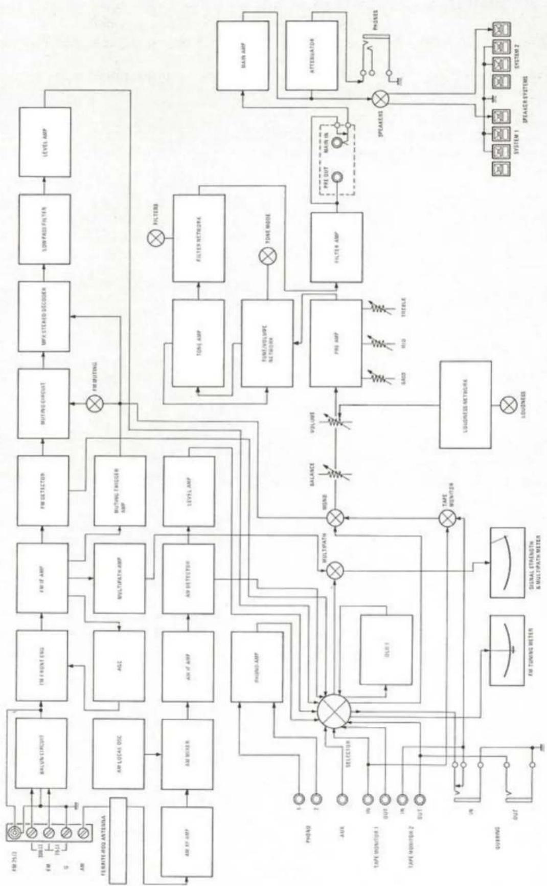
Figure 10. Functional Block Diagram
TECHNICAL DESCRIPTION
GENERAL
Figure 10 is a block diagram of the Model 2330B Receiver showing the main functional elements and input and output signal routing. Each AM and FM front end has its own IF stages. For clarity, only the left audio channel is shown; the right audio channel is identical. All audio controls are ganged or concentrically clutched to their counterparts in the right channel. The left channel half of the front panel DUBBING IN and DUBBING OUT jacks are shown interconnected in this diagram. The right channel of each jack is wired to the same circuit point in the right channel.
FM TUNER SECTION
FRONT END - FM antenna signals are applied through a balun transformer to the antenna coil which drives a dual gate MOSFET (Metal Oxide Semiconducting Field Effect Transistor) RF amplifier. The amplified signals from the RF amplifier are fed through the double-tuned RF filter circuit to the dual gate MOSFET Mixer stage, which also receives the signal generated by the local oscillator. A four section tuning capacitor tunes antenna, interstage and oscillator circuits which provide exceptional selectivity and spurious signal rejection. The mixer converts the carrier frequency to the 10.7 MHz intermediate frequency. Careful attention to the local oscillator's thermal and electrical characteristics has minimized drift, thus obviating the necessity for AFC. The 10.7 MHz converted signal is then fed to the IF amplifier.
IF AMPLIFIER — The IF section consists of a first stage input amplifier, four dual element ceramic filters, an intermediate IC amplifier and a final IC amplifier which includes limiter stages, a linear quadrature detector, together with the circuits necessary for FM muting. The ceramic filters have been designed for optimum phase linearity across the 200 kHz passband, thereby reducing a major source of high frequency distortion and loss of stereo separation. The sharp cut-off slopes of these filters provide the selectivity necessary to permit the reception of closely spaced FM channels.
MULTIPATH INDICATOR - The Multipath Indicator circuit is provided to indicate the optimum antenna direction for a desired station. Undesirable amplitude modulation resulting from multipath reception is sampled and detected from the IF amplifier and is displayed on the MULTIPATH meter when the MULTIPATH pushswitch is held "in". By orienting the antenna for minimum meter deflection, minimum multipath condition is obtained.
STEREO DEMODULATOR - The stereo composite signal obtained from the quadrature detector is fed to the MPX IC. The L and R signal outputs from the MPX IC are applied through the lowpass filter and the de-emphasis circuit to the two (per channel) transistor amplifier. The output (about 1700 mV) obtained from this amplifier is fed to the SELECTOR switch.
This stereo demodulating IC employs a PLL (Phase Locked Loop) technique, whereby the phase of the 38 kHz switching carrier signal in the decoder is constantly interlocked with the phase of the 19 kHz input pilot signal. Phase shift of the switching carrier (38 kHz) is thereby eliminated and deterioration of separation and distortion do not occur.
The stereo demodulating 38 kHz carrier switching signal is very clean with no even harmonic content. SCA rejection of approximately 80 dB is obtained since resonant beats are not generated between the secondary harmonic (76 kHz) of the 38 kHz carrier switching signal and the SCA signal (67 ± 7 kHz).
MUTING CIRCUIT - In the absence of an FM carrier, all FM receivers produce interstation noise. The muting circuit eliminates this noise, providing noise-free tuning from station to station. The muting circuit perfectly mutes out all the interstation noise and also completely mutes out the side slope spurious response of the unit. The circuit has been designed to minimize annoying switching noise as the tuning band is scanned.
AM TUNER SECTION
The AM tuner section of the Model 2330B is composed of one IC (incorporating an RF amplifier, local oscillator, mixer, IF amplifier and
detector) and one transistor audio amplifier which amplifies the detected audio signals. A three section variable capacitor is used to insert two tuned circuits into the RF stage for high selectivity and improved spurious signal rejection performance. The ceramic filters utilized in the AM IF amplifier are designed for higher selectivity and wider bandwidth for interference-free high quality AM reception. Following the AM IF amplifier, the AM detector recovers the audio modulation and presents this signal to the SELECTOR switch. The AM tuner and IF amplifier are subjected to the action of an effective automatic gain control circuit which maintains a constant signal level for all stations in the AM band.
AMPLIFIER SECTION
SELECTOR SWITCH — The SELECTOR switch selects one of six inputs for selection to the TAPE MONITOR switches and TAPE MONITOR 1 OUT, TAPE MONITOR 2 OUT, and DUBBING OUT jacks.
PHONO AMPLIFIER — Phono signals of up to 200 millivolts can be handled without overloading. The RIAA equalization network provides precise equalization and sets the voltage gain of the phono preamplifier to 40 dB (at 1,000 Hz).
MPX NOISE FILTER - When the MPX NOISE FILTER switch is depressed, the left and right channel outputs of the SELECTOR switch are connected together through mixing resistors and a capacitor. The value of the capacitor has been selected to effect moderate suppression of out-of-phase noise and distortion components while maintaining moderate stereo separation.
BALANCE CONTROL — The change of alternation in each channel as the control is moved from center has been designed to decrease the level in one output channel while maintaining the level in the other channel.
VOLUME CONTROL – The VOLUME control attenuates both channels simultaneously. Since the control is situated at the input of the tone amplifier, there is no possibility of overloading the tone amplifier stages when large signals are presented to the AUX and tape inputs. This, distortion is kept to a minimum. After attenuation by the BALANCE and VOLUME controls, the signal is applied to the tone control amplifier.
line
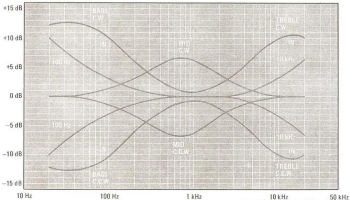
| Frequency | BASS C.W. (100 Hz) | BASS C.W. (1 kHz) | BASS C.W. (50 kHz) | MIO C.W. (100 Hz) | MIO C.W. (1 kHz) | MIO C.W. (50 kHz) | TREBLE C.W. (100 Hz) | TREBLE C.W. (1 kHz) | TREBLE C.W. (50 kHz) | | --------- | ------------------ | ----------------- | ------------------ | ----------------- | ---------------- | ----------------- | -------------------- | ------------------- | -------------------- | | 10 Hz | +12.5 | +12.5 | +12.5 | +10 | +10 | +10 | +10 | +10 | +10 | | 100 Hz | +8 | +8 | +8 | -5 | -5 | -5 | -5 | -5 | -5 | | 1 kHz | -5 | -5 | -5 | -10 | -10 | -10 | -10 | -10 | -10 | | 10 kHz | +5 | +5 | +5 | +5 | +5 | +5 | +5 | +5 | +5 | | 50 kHz | +12.5 | +12.5 | +12.5 | +10 | +10 | +10 | +10 | +10 | +10 |Figure 11. Tone Control Characteristics
TONE CIRCUIT – The tone amplifier is a unity gain dual feedback pair design. We employed the Baxandall type of tone control, because it tends to concentrate the boost or cut in the lowest bass range without undue affect on the lower mid-range frequencies. This offers more natural compensation for the variety of loudspeakers and peripheral equipment that this model would likely be used with.
The turnover switch adjusts the turnover frequency of the bass (400 Hz or 100 Hz) and treble (3 kHz or 10 kHz) controls and this increases the flexibility of the tone circuit. (See Figure 11).
The loudness compensation, as with all Marantz equipment, provides a Fletcher-Munson type frequency response correction curve, offering both bass and treble boost to compensate for the human ear's characteristic at low volume levels.
OUTPUT STAGE AND PROTECTIVE CIRCUITS - With the controls set for flat response and VOLUME control at maximum, the over-all voltage gain from any high-level input to the loudspeaker terminals is approximately 45 dB. The differential amplifier and pre-driver circuit amplify the signal from the 9 KHz and 15 Hz FILTERS to sufficient levels to drive the output stages. From the input of the differential amplifier circuit, the amplifier stages are direct coupled through to the loudspeakers (and headphones) providing instantaneous recovery from any overdriven condition. The output stage consists of four push-pull, parallel complementary symmetry power transistors (PNP, NPN), having massive current and dissipation capabilities. The electronic protection circuit senses excessive output current and voltage conditions and limits the signal to the driver transistors to a safe, pre-determined value. This limiting action protects the driver and output transistors from excessive overdrive and short circuit conditions. The instantaneous acting nature of the safety circuit gives constant and unobtrusive protection without causing annoying program interruptions. Thermal compensation circuits are also provided to ensure highly stable operation under severe temperature and signal handling conditions.
A speaker protection relay protects the speakers in the event of transistor failure, and eliminates low frequency transients when the unit is truned on or off.
line
| Frequency | 15 Hz FILTER (dB) | 9 kHz FILTER (dB) | | --------- | ----------------- | ----------------- | | 1 Hz | -20 | -20 | | 10 Hz | -8 | -8 | | 1 kHz | 0 | 0 | | 10 kHz | -8 | -8 | | 50 kHz | -20 | -20 |Figure 12. 15 Hz and 9 kHz Filter Characteristics
SERVICE NOTES
Because the Model 2330B Stereo Receiver is completely solid state, replacement of parts should never be required. If the pilot lamp burns out, have your serviceman replace it.
FUSE REPLACEMENT
The Model 2330B is protected by an 8-amp fuse. In the event the fuse blows out, replace it ONLY with a fuse of the same type and rating. Replacement with a fuse of higher rating will not protect the instrument and will void the warranty.
The unit power should be switched OFF before replacing the fuse. Should the replacement fuse blow out within a short period of time after the unit is turned on, the unit should be taken to an authorized service facility.
CLEANING
Your Model 2330B Stereo Receiver has a very durable finish. The front panel and knobs are gold anodized for lasting beauty. You can clean the panel and knobs with a liquid solution of mild detergent and water applied with a soft cloth or cotton-tipped swab. Never use scouring powder or any abrasive cleaner.
IN CASE OF DIFFICULTY
Should you experience difficulties when operating your system for the first time, and you have followed the procedure outlined in the "Simplified Operating Procedures", use of the following data will help you correct or isolate the problem. If these hints fail to remedy the situation, refer the problem to your nearest authorized service facility.
Receiver does not operate, and dial lamps do not illuminate.
- Make sure power cord is properly connected.
- Check AC line fuse; replace if necessary (the unit should be OFF when replacing the fuse).
Receiver does not operate, but dial lamp is on.
- Check settings of controls such as SELECTOR, TAPE MONITOR, SPEAKERS switches VOLUME, etc.
- Turn off POWER and check connection of cables from turntables, tape decks, speakers, and other equipment. Make sure speaker wires are not shorted together.
Receiver operates in one channel only.
- Check setting of BALANCE control.
- Turn MODE switch to REVERSE. If opposite channel becomes inoperative, either the input equipment or the cables connecting it to the receiver are at fault.
- Turn off system power and transpose (left for right) the speaker cables at the SPEAKER SYSTEMS terminals. If opposite channel becomes inoperative when turned back on, either the cable or speaker is at fault.
No FM reception.
- Release FM MUTING switch.
- Connect FM antenna.
FM reception sounds scratchy or raspy.
- Make sure FM antenna is connected properly.
- Try re-orienting FM antenna.
- Determine if you are in a poor reception area. If so, refer to "OUTDOOR FM ANTENNAS" section.
AM reception poor.
- Swing out AM ferrite-rod antenna on rear panel.
- Re-orient the AM ferrite-rod antenna.
- Determine if other components in your system, appliances, or fluorescent lights are causing interference.
- Try an outdoor AM antenna. See "OUTDOOR AM ANTENNA" section.
Loud hum in phono.
- Check to see that phono plugs and jacks are clean and properly connected.
- Try connecting turntable ground wire (usually colored green) to CHASSIS GROUND post on rear panel of receiver.
- If ground wire is already connected, try disconnecting it.
- Make sure phono cartridge is wired properly and making good contact with terminals in tone arm.
Tone controls don't work.
- Turn TONE MODE switch to IN position.
REPAIRS
Only the most competent and qualified service technicians should be allowed to service the Model 2330B. The Marantz Company and its factory-trained warranty station personnel have the knowledge and special equipment needed for repair and calibration of this precision instrument.
In the event of difficulty, call the toll free telephone number listed on the back of the Warranty to obtain the name and address of the Marantz Authorized Service Station nearest your home or business. In many cases, the dealer where you purchased your Marantz unit will be equipped to provide service.
REPACKING FOR SHIPMENT
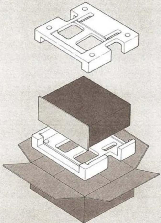
Should it become necessary to repack your Model 2330B for shipment to the factory, to an authorized service station, or elsewhere, please observe the following precautions:
a. Do not ship the unit installed in its accessory walnut cabinet; remove the unit from the cabinet before packing.
b. Pack the unit carefully, using the original material as shown in Figure 13.
PLEASE NOTE that if you have discarded, lost, or damaged the packing material, new packing material may be obtained by writing to the Marantz Technical Services Department. The carton, its fillers, and packing instructions will be returned to you at a nominal charge.
c. Ship via a reputable carrier (do not use Parcel Post) and obtain a shipping receipt from the carrier.
d. Insure the unit for its full value.
e. Be sure to include your return address on the shipping label.
natural_image
Technical illustration of a mechanical assembly with two views: top shows a bracket component, bottom shows a stacked box (no text or symbols)Figure 13. Packing Instructions
MODEL 2330B TECHNICAL SPECIFICATIONS
AMPLIFIER SECTION:
RATED POWER OUTPUT, MINIMUM
CONTINUOUS AVERAGE POWER PER
CHANNEL, BOTH CHANNELS DRIVEN 130 W
POWER BAND 20 Hz to 20 kHz
TOTAL HARMONIC DISTORTION 0.05%
LOAD IMPEDANCE 8 ohms
RATED POWER OUTPUT, MINIMUM
CONTINUOUS AVERAGE POWER PER
CHANNEL, BOTH CHANNELS DRIVEN 165 W
POWER BAND 20 Hz to 20 kHz
TOTAL HARMONIC DISTORTION 0.1%
LOAD IMPEDANCE 4 ohms
I.M. Distortion
(I.H.F. method, 60 Hz and 7 kHz mixed 4:1 at rated power output)
at 8 ohm load impedance 0.05%
at 4 ohm load impedance 0.1%
Damping Factor (at 20 Hz) 60
Sensitivity (at MAIN IN) 1.5 V
Impedance (at MAIN IN) 45 k ohms
Frequency Response for Power Amp Only
(at 1 Watt output, 20 Hz to 20 kHz) ±0.2 dB
PREAMPLIFIER SECTION:
Phono
Input Overload at 1 kHz 200 mV
Equivalent Input Noise 1.0 μV
Dynamic Range
(Dynamic Range is the ratio of input overload to equivalent input noise) 106 dB
Input Sensitivity 1.8 mV
Input Impedance 47 k ohms
Input Capacitance 100 pF
Frequency Response, RIAA 20 Hz to 20 kHz ±0.5 dB
Signal-to-Noise Ratio
(at rated output and 7.75 mV input) 78 dB
High Level (Aux and Tape)
Input Sensitivity 180 mV
Input Impedance 20 k ohms
Frequency Response
(includes power amp) 10 Hz to 60 kHz ±1.0 dB
Signal-to-Noise Ratio
(ref. to rated output and 775 mV input) 95 dB
Output Levels
Tape Out (ref. 7.75 mV at Phono inputs) 775 mV
Pre-Out (ref. 180 mV at Aux inputs) 1.5 V
(ref. 500 mV at Aux inputs, main amp disconnected) 4.2 V
Output Impedance
Tape Out 500 ohms
Pre-Out 500 ohms
FM TUNER SECTION:
Sensitivity
IHF Usable 10.3 dBf (1.8 μV)
IHF 50 dB Quieting (Mono) 13.2 dBf (2.5 μV)
(Stereo) 36 dBf (35 μV)
Quieting Slope (Mono)
RF Input for 30 dB Quieting 7.5 dBf (1.3 μV)
Quieting at:
20 dBf ( 5.5 μV) 58 dB
25 dBf ( 10 μV) 63 dB
40 dBf ( 55 μV) 72 dB
65 dBf (1000 μV) 78 dB
Quieting Slope (Stereo)
Quieting at:
30 dBf ( 17 μV) 43 dB
40 dBf ( 55 μV) 53 dB
50 dBf (173 μV) 60 dB
65 dBf (1000 μV) 70 dB
Distortion (Mono) at 65 dBf (1000 μV)
100 Hz 0.2%
1000 Hz 0.1%
6000 Hz 0.3%
Distortion (Stereo) at 65 dBf (1000 μV)
100 Hz 0.35%
1000 Hz 0.2%
6000 Hz 0.5%
Distortion (Mono and Stereo)
at 50 dB Quieting, 1000 Hz 0.6%
Hum and Noise
at 65 dBf (1000 μV)
Mono 78 dB
Frequency Response
30 Hz to 15 kHz Mono +0.2 dB -1.0 dB
Stereo ±1.5 dB
Capture Ratio at 65 dBf (1000 μV) 1.0 dB
Alternate Channel Selectivity 80 dB
Spurious Response Rejection 100 dB
Image Response Rejection 90 dB
I.F. Rejection (Balanced) 100 dB
A.M. Suppression 57 dB
Stereo Separation
100 Hz 42 dB
1000 Hz 50 dB
10 kHz 42 dB
Subcarrier Rejection 42 dB 70 dB
AM TUNER SECTION:
IHF Usable Sensitivity 10 μV
Distortion (THD), 30% Modulation 0.4%
Signal-to-Noise Ratio 54 dB
Alternate Channel Selectivity 46 dB
Image Rejection 45 dB 75 dB
Spurious Response Rejection 75 dB 85 dB
I.F. Rejection 65 dB 75 dB
General:
Power Requirements 120 V AC 60 Hz
Power Consumption at rated output, both channels operating 550 W
Idling Power (Volume Control at zero) 65 W
Dimensions:
Panel Width 490 mm (19-1/4")
Panel Height 146 mm (5-3/4")
Depth 387 mm (15-1/4")
Weight:
Unit alone 22.0 kg (48.4 lbs)
Packed for Shipment 24.9 kg (54.8 lbs)