
P-870H - Router ZYXEL - Kostenlose Bedienungsanleitung
Finden Sie kostenlos die Bedienungsanleitung des Geräts P-870H ZYXEL als PDF.


| Produkttyp | VDSL2-Router mit integriertem 4-Port-Switch und WLAN (802.11b/g) |
| Abmessungen (ca.) | 200 x 150 x 30 mm |
| Gewicht (ca.) | 300 g |
| Stromversorgung | 12 V Gleichspannung, 1 A (Netzteil im Lieferumfang) |
| WLAN-Standard | IEEE 802.11b/g, max. 54 Mbit/s |
| LAN-Ports | 4x 10/100/1000 Ethernet (RJ-45) |
| WAN-Schnittstelle | VDSL2 (ITU G.993.2), kompatibel zu ADSL2+ |
| Unterstützte Protokolle | PPP over Ethernet (PPPoE), IP over Ethernet (IPoE), Bridging, IGMP |
| Network Address Translation (NAT) | Ja, mit Multi-NAT, Port-Weiterleitung, DMZ |
| Firewall | Stateful Packet Inspection (SPI), ACL-Regeln, DoS-Schutz |
| Quality of Service (QoS) | Ja, Verkehrsklassifizierung und Priorisierung |
| IGMP Multicast Proxy | Ja, für IPTV |
| TR-069 | Ja, Fernverwaltung und -aktualisierung |
| Verschlüsselung | WEP (64/128 Bit), WPA, WPA-PSK (TKIP/AES), 802.1x |
| Zubehör | Netzteil, Ethernet-Kabel, Kurzanleitung |
Häufig gestellte Fragen - P-870H ZYXEL
Benutzerfragen zu P-870H ZYXEL
0 Frage zu diesem Gerät. Beantworten Sie die, die Sie kennen, oder stellen Sie Ihre eigene.
Eine neue Frage zu diesem Gerät stellen
Laden Sie die Anleitung für Ihr Router kostenlos im PDF-Format! Finden Sie Ihr Handbuch P-870H - ZYXEL und nehmen Sie Ihr elektronisches Gerät wieder in die Hand. Auf dieser Seite sind alle Dokumente veröffentlicht, die für die Verwendung Ihres Geräts notwendig sind. P-870H von der Marke ZYXEL.
BEDIENUNGSANLEITUNG P-870H ZYXEL
P-870H/HW-51a v2
VDSL2 4 port gateway/802.11bg Wireless VDSL 4 port gateway
Support Notes
Firmware Version 1.00AWZ.4
August 2009
Edition 2.0
INDEX
Application Notes......5
General Application Notes ...... 6
Why use P-870HW-51aV2? 6
Application Scenario 7
Prologue 9
Access Application Notes ...... 11
Web GUI 11
Telnet....12
Internet Connection 13
Bridge Mode 13
IPoE Mode 15
PPPoE Mode 19
IGMP Multicast Proxy 23
IP Multicast Introduction ...... 23
IGMP Multicast Proxy Configuration 24
Protocol Based Scenario 25
Environment....25
WAN Configuration 26
VLAN Based Scenario 33
Environment....33
WAN Configuration 34
Quality of Service 43
Environment....43
QoS configuration 44
TR069 – Remote Firmware Upgrade 47
Environment....47
TR069 Configuration 48
NAT Portforwarding 49
NAT/Multi-NAT Introduction 49
Environment....52
Port Forwarding Configuration 53
DMZ Host Configuration 56
IP Filter 58
Environment....58
IP Filter Configuration 59
Configuration of Accepting Incoming Traffic 61
LAN Connection 64
IP Alias Introduction 64
IP Alias Configuration 65
Maintenance Log 66
Internal Maintenance 66
Remote Maintenance 68
Maintenance Tool 69
Maintenance Procedure 69
Wireless Application Notes 72
Wireless Introduction 72
Wireless Configuration 82
WPS Application Notes 93
What is WPS? 93
WPS configuration....94
FAQ 96
Product FAQ 96
Will the device work with my Internet connection? 96
Why do I need to use P-870HW-51aV2? 96
What is PPPoE? 96
Does the device support PPPoE? 96
How do I know I am using PPPoE? 97
Why does my provider use PPPoE? 97
Which Internet Applications can I use with the device? 97
How can I configure the device? 97
What network interface does the device support? 97
What can we do with the device? 97
Does device support dynamic IP addressing? 98
What is the difference between the internal IP and the real IP from my ISP?
98
How does e-mail work through the device? 98
Is it possible to access a server running behind SUA from the outside
Internet? If possible, how? 98
What DHCP capability does the device support? 99
How do I used the reset button, more over what field of parameter will be
reset by reset button? 99
What network interface does the new device series support? 99
How does the device support TFTP? 99
Can the device support TFTP over WAN? 99
How fast can the data go? 100
What is Multi-NAT? 100
When do I need Multi-NAT? 101
What IP/Port mapping does Multi-NAT support? 101
What is the difference between SUA and Multi-NAT? 102
What is BOOTP/DHCP?...... 103
What is DDNS? 103
When do I need DDNS service? 103
Wireless FAQ 104
What is a Wireless LAN? 104
What are the advantages of Wireless LANs? 104
What are the disadvantages of Wireless LANs? 105
Where can you find wireless 802.11 networks? 105
What is an Access Point? 105
What is IEEE 802.11? 105
What is 802.11b?....105
How fast is 802.11b?...... 106
What is 802.11a?....106
What is 802.11g?....106
Is it possible to use products from a variety of vendors? 106
What is Wi-Fi? 107
What types of devices use the 2.4GHz Band? 107
Does the 802.11 interfere with Bluetooth devices? ...... 107
Can radio signals pass through walls? 107
What are potential factors that may causes interference among WLAN products?....108
What's the difference between a WLAN and a WWAN? 108
What is Ad Hoc mode? 108
What is Infrastructure mode? 108
How many Access Points are required in a given area? 108
What is Direct-Sequence Spread Spectrum Technology - (DSSS)? ...... 109
What is Frequency-hopping Spread Spectrum Technology – (FHSS)? .... 109
Do I need the same kind of antenna on both sides of a link? 109
Why the 2.4 Ghz Frequency range? .... 109
What is Server Set ID (SSID)? 109
What is an ESSID? 110
How do I secure the data across an Access Point's radio link? 110
What is WEP? 110
What is the difference between 40-bit and 64-bit WEP? .... 110
What is a WEP key? 110
A WEP key is a user defined string of characters used to encrypt and decrypt data? 111
Can the SSID be encrypted? 111
By turning off the broadcast of SSID, can someone still sniff the SSID? . 111
What are Insertion Attacks? 111
What is Wireless Sniffer? 111
What is the difference between Open System and Shared Key of Authentication Type? 112
What is 802.1x? 112
What is the difference between No authentication required, No access allowed and Authentication required? 112
What is AAA? 113
What is RADIUS? 113
What is WPA? 113
What is WPA-PSK? 113
Trouble Shooting....114
How to enter the “Shell mode” 114
CPU usage 115
Memory usage 115
Current processes ...... 116
IGMP table 116
Packets statistics.... 117
Physical layer statistics ...... 117
CLI Command List....118
General Application Notes
Why use P-870HW-51aV2?
• High Speed Internet Access
The P-870HW-51aV2 is a VDSL gateway supporting the downstream transmission up to 100Mbps and upstream transmission up to 50 Mbps.
• Quality of Service (QoS)
The P-870HW-51aV2 with Quality of Service features ensures that the Triple Play Service keeps the high quality delivery in VDSL high speed Internet access.
- PPP over Ethernet
Since the PPPoE will benefit both Telco and ISP, the P-870H/HW-51 V2 shall implement this feature and be tested well with the PPPoE servers.
- Multi-NAT
The NAT provides system administrators an easy solution to create a private IP network for the security and IP management. Powered by NAT technology, the P-870HW-51aV2 supports the complete NAT mapping and most popular Internet multimedia applications, such as NetMeeting, MSN Messenger, Skype, ICQ, IPTV, QuickTime, Real Player (RSP/RTSP), VoIP SIP ALG, etc.
Application Scenario
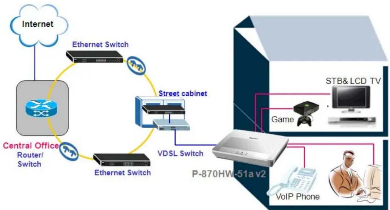
FTTx - FTTC Solution
flowchart
graph TD
    A["Internet"] --> B["Central Office Router/Switch"]
    B --> C["Ethernet Switch"]
    C --> D["Street cabinet"]
    D --> E["VDSL Switch"]
    E --> F["P-870HW-51a v2"]
    F --> G["STB& LCD TV"]
    F --> H["Game"]
    F --> I["VoIP Phone"]
    B --> J["Ethernet Switch"]
A typical scenario is used with P-870HW-51aV2 in a FTTC (Fiber to the Curb) solution. The P-870HW-51aV2 serves as a home gateway, providing the high speed INTERNET service and High Quality IPTV service. The COE (VDSL switch) is located in a street cabinet, providing a high speed service within a 700 feet range, assuring the bandwidth reaching up to 100/50Mbps (Downstream/Upstream) at maximum.
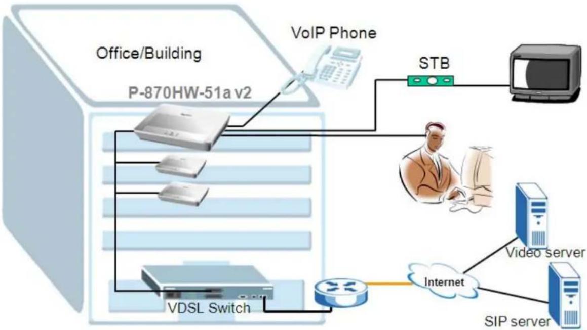
FTTx - FTTB Solution
flowchart
graph TD
    A["Office/Building P-870HW-51a v2"] --> B["VoIP Phone"]
    B --> C["STB"]
    C --> D["Video server"]
    D --> E["SIP server"]
    E --> F["Internet"]
    F --> G["VDSL Switch"]
    G --> H["Server"]
An often seen scenario is used with P-870HW-51aV2 in a FTTB (Fiber to the Building) solution. The P-870HW-51aV2 serves as a home gateway, providing the high speed INTERNET service, High Quality IPTV service and VoIP service. The COE (VDSL switch) is located inside the cabinet of building, providing a high speed service covering the whole apartment, assuring the bandwidth reaching up to 100/50Mbps (Downstream/Upstream) at maximum.
Prologue
- Before we begin.
The device is shipped with the following factory defaults:
-
IP address = 192.168.1.1, subnet mask = 255.255.255.0 (24 bits)
-
DHCP server enabled with IP pool starting from 192.168.1.33
-
Default username/password = 1234/1234
- Setting up the PC (Windows OS)
1. Ethernet Connection
• All PCs must have an Ethernet adapter card installed
2. TCP/IP Installation
You must first install the TCP/IP software on each PC before you can use it for the Internet access. If you have already installed the TCP/IP, go to the next section to configure it; otherwise, follow these steps to install:
• In the Control Panel/Network window, click Add button.
- In the Select Network Component Type windows, select Protocol and click Add.
- In the Select Network Protocol windows, select Microsoft from the manufacturers, then select TCP/IP from the Network Protocols and click OK.
3. TCP/IP Configuration
Follow these steps to configure Windows TCP/IP:
- In the Control Panel/Network window, click the TCP/IP entry to select it and click Properties button.
• In the TCP/IP Properties window, select obtain an IP address automatically.
Note: Do not assign the arbitrary IP address and subnet mask to your PCs; otherwise, you will not be able to access the Internet.
- Click the WINS configuration tab and select Disable WINS Resolution.
- Click the Gateway tab. Highlight any installed gateways and click the Remove button until there are none listed.
- Click the DNS Configuration tab and select Disable DNS.
- Click OK to save and close the TCP/IP properties window.
- Click OK to close the Network window. You will be prompted to insert your Windows CD or disk. When the drivers are updated, you will be asked if you want to restart the PC. Make sure that your Device is powered on before answering "Yes" to the prompt. Repeat the aforementioned steps for each Windows PC on your network.
Access Application Notes
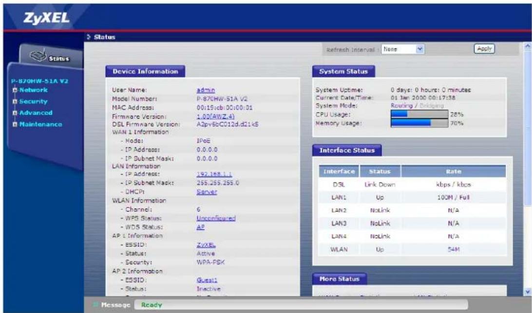
Web GUI
The following procedure is for the most typical usage of device using a Browser. The device supports the embedded Web server that allows you to use Web browser to configure it. Before configuring the router using Browser, please be sure there is no Telnet or Console login.
a. Login the P-870HW-51a v2 via Web GUI.
- Set up your PC/NB IP address to be a DHCP client.
- Connect to a LAN port of P-870HW-51a v2 via RJ45 Ethernet cable and open your IE browser.
- The default IP of P-870HW-51a v2 is 192.168.1.1 username/password = admin/1234.
Telnet
Telnet is also a common way to configure the device, but we have to use CI commands which may not be quick-to-learn. The list of the commonly used CI commands is provided at the end of this document.
b. Login the P-870HW-51a v2 via Telnet.
- Set up your PC/NB IP address to be a DHCP client.
- Connect to a LAN port of P-870HW-51a v2 via RJ45 Ethernet cable and open your Hyper Terminal software (capable of using TELNET).
- The default IP of P-870HW-51a v2 is 192.168.1.1 username/password = admin/1234.
- Type the command line "atsh" to display the basic information of device.
ZyXEL xDSL Router
Login: admin
Password:
> atsh
ZLO Version : U1.00(AW2.4)
Bootbase Version : U1.03 | 07/06/2009
Vendor Name : ZyXEL Communications Corp.
Product Model : P-870H/HW-51A V2
First MAC Address : 0019CB020001
Last MAC Address : 0019CB020006
MAC Address Quantity : 06
Default Country Code : FF
Boot Module Debug Flag : 01
RootFS Checksum : 3571c004
Kernel Checksum : 7426134f
RomFile Checksum : f39d787f
Main Feature Bits : 00
Other Feature Bits :
5a 59 00 01 00 00 01 00-00 00 00 00 00 00 00
00 00 00 00 00 00 00-00 03 +1 13 00 00
>
Internet Connection
Bridge Mode
Scenario:
The P-870HW-51a v2 is a CPE bridge.
a. Bridge Mode
- Go to Network > WAN > Internet Connection.
- Click Add
- Select the Layer 2 interface for this service, e.g "ptm0/(0_0_1)"
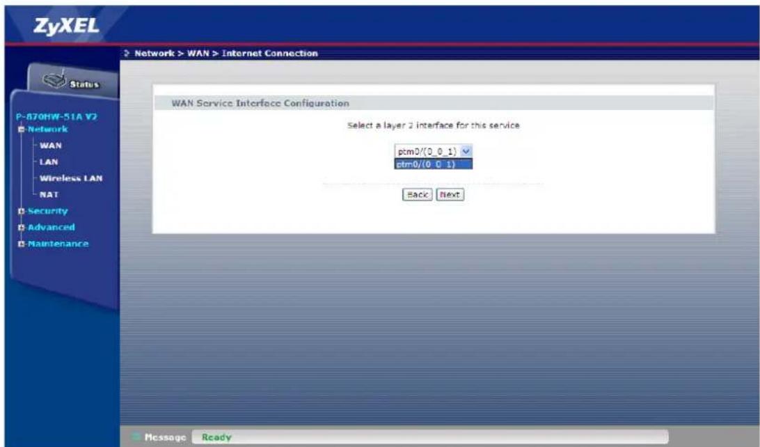
- Click Next
- Select the WAN service type, i.e. "Bridging"
- Enter the Service Description, e.g. "Internet"
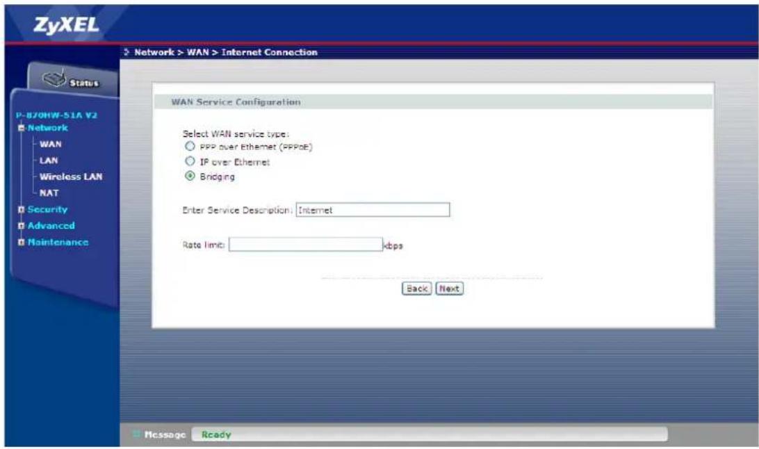
- Click Next
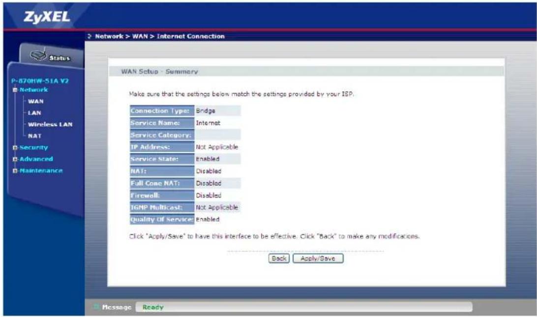
- Click Apply/Save
IPoE Mode
Scenario:
The P-870HW-51a v2 is a DHCP client in routing mode.
b. IPoE Mode
- Go to Network > WAN > Internet Connection.
- Click Add
- Select the Layer 2 interface for this service, e.g "ptm0/(0_0_1)"
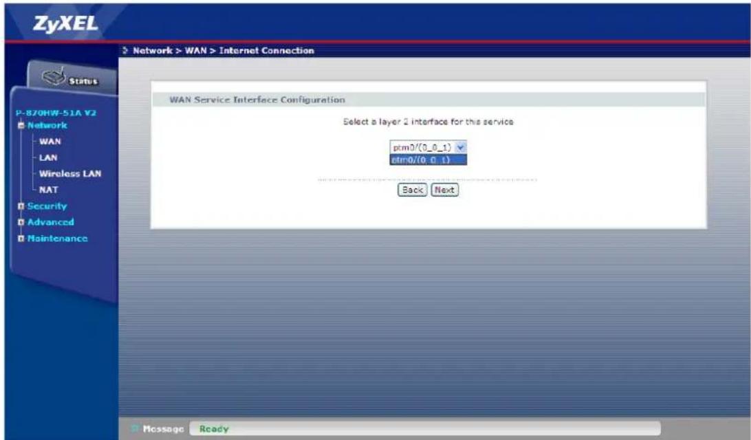
- Click Next
- Select the WAN service type, i.e. "IP over Ethernet"
- Enter the Service Description, e.g. "Internet"
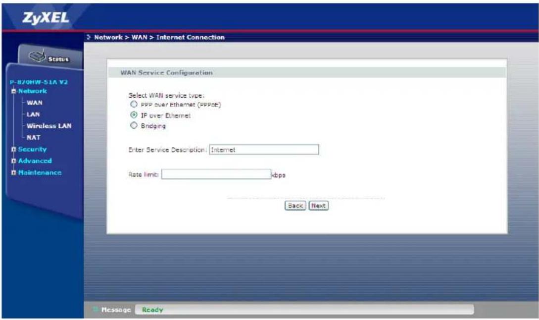
- Click Next
- Select Obtain an IP address automatically
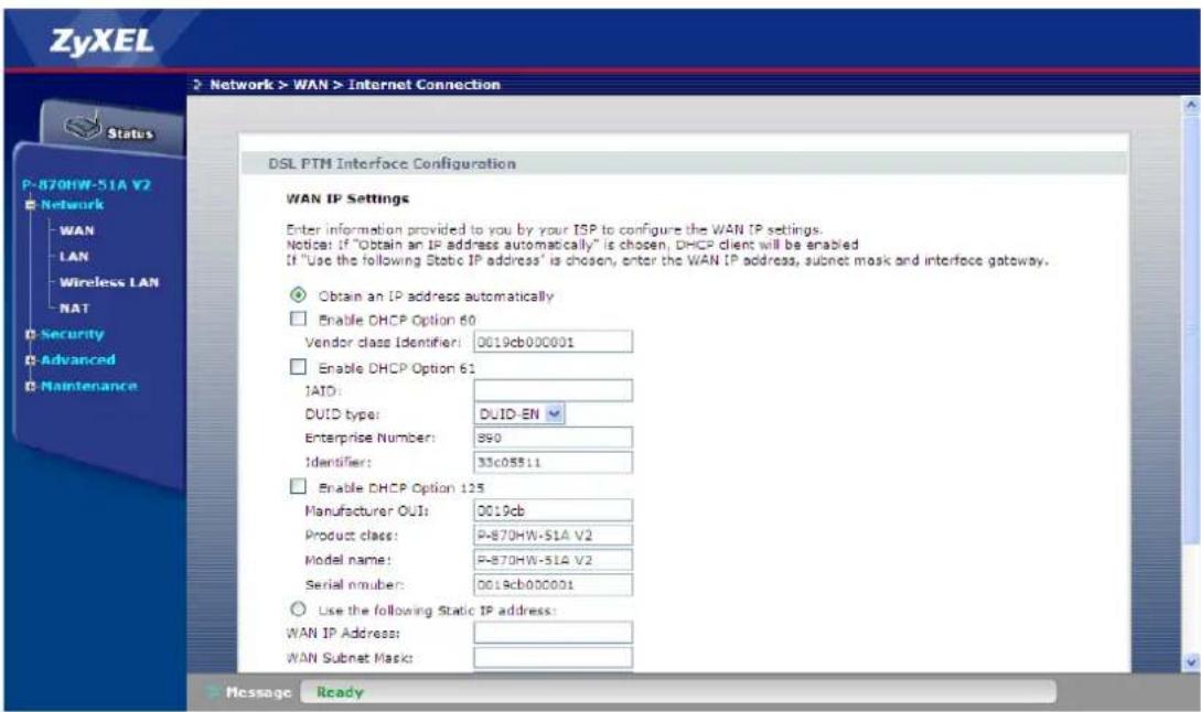
- Click Next
- Select Enable NAT
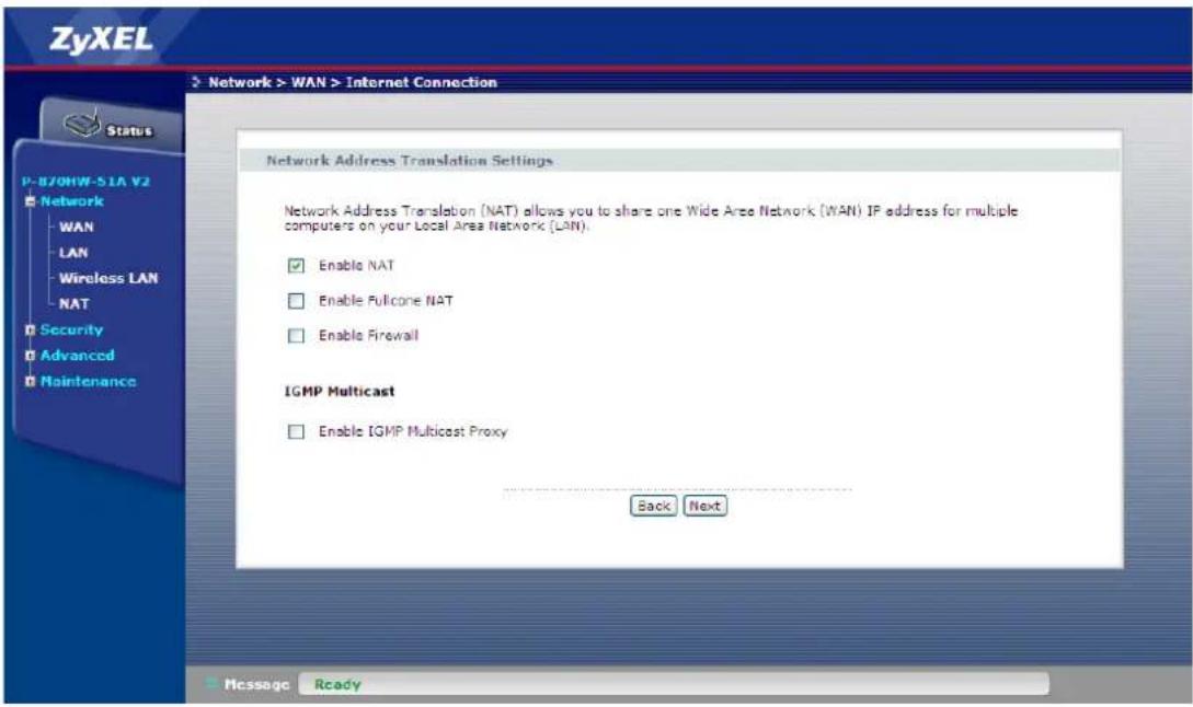
- Click Next
- Select the WAN Interface, e.g. "Internet/ptm0_1" for the default gateway
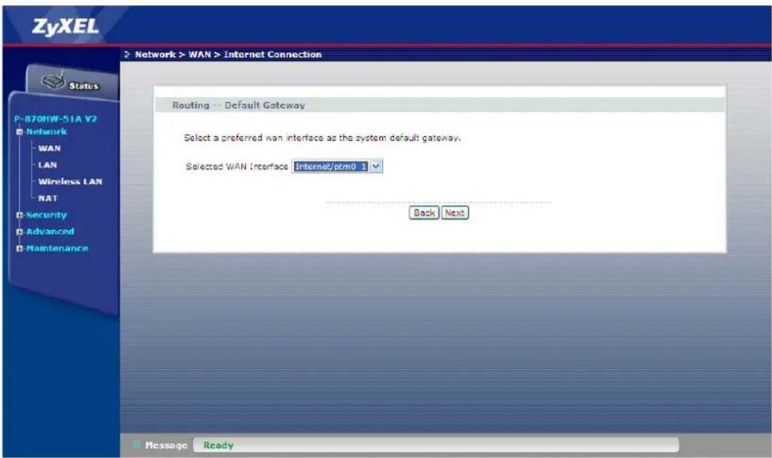
- Click Next
- Select Obtain DNS info from a WAN interface and select the interface
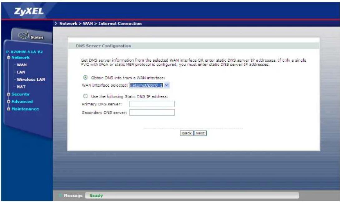
- Click Next
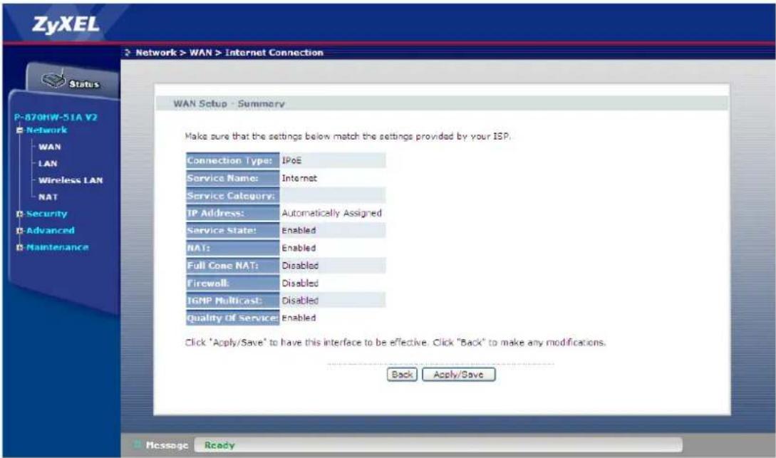
- Click Apply/Save
PPPoE Mode
Scenario:
The P-870HW-51a v2 is a PPPoE client.
c. PPPoE Mode
- Go to Network > WAN > Internet Connection.
- Click Add
- Select the Layer 2 interface for this service, e.g "ptm0/(0_0_1)"
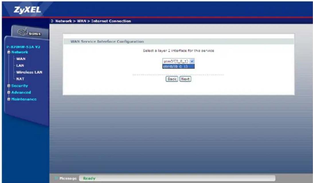
- Click Next
- Select the WAN service type, i.e. "PPP over Ethernet (PPPoE)"
- Enter the Service Description, e.g. "Internet"
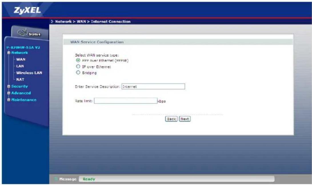
- Click Next
- Enter the PPP Username, e.g. "test@isp.net"
- Enter the PPP Password, e.g. "1234"
- Enter the PPPoE Service Name, e.g. "PPPoE"
- Select the Authentication Method to be "AUTO"
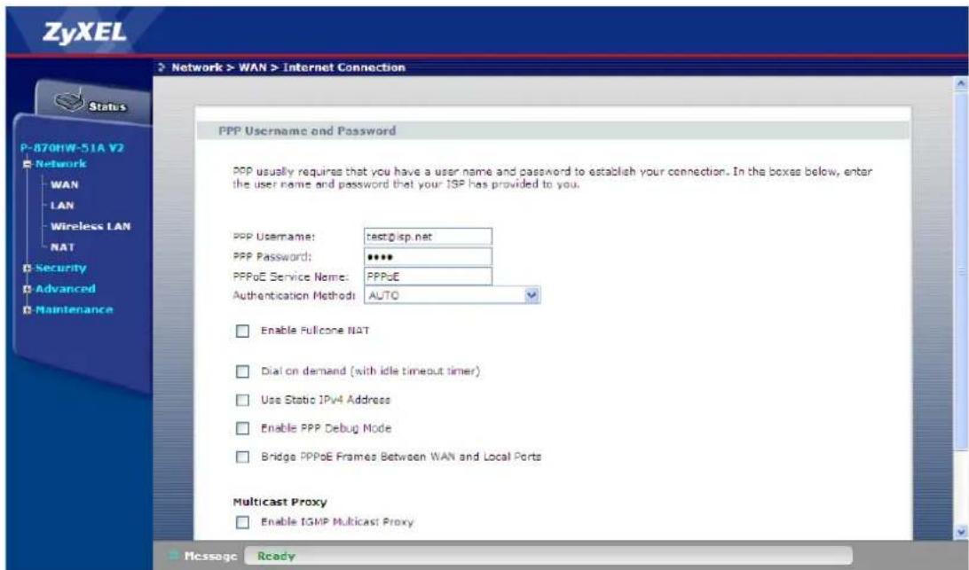
- Click Next
- Select the WAN Interface, e.g. "Internet/ppp0_1" for the default gateway
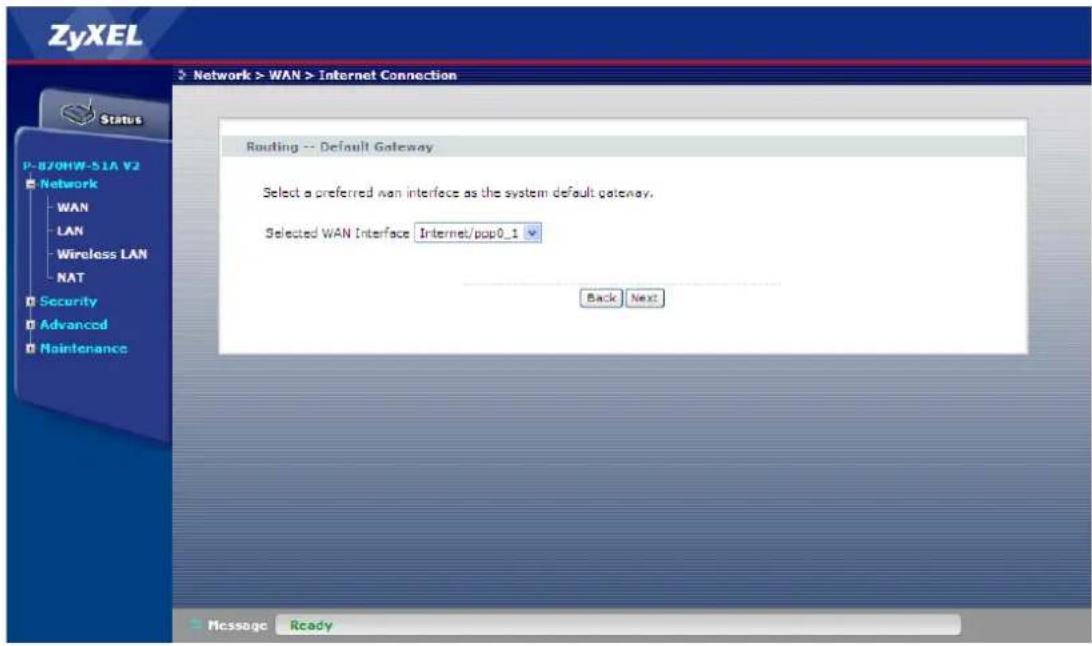
- Click Next
- Select Obtain DNS info from a WAN interface and select the interface
![ZyXEL Network > WAN > Internet Connection Status P-870HW-51A V2 Network WAN LAN Wireless LAN NAT Security Advanced Maintenance DNS Server Configuration Get DNS server information from the selected WAN interface OR enter static DNS server IP addresses. If only a single PVC with IPoA or static MER protocol is configured, you must enter static DNS server IP addresses. Obtain DNS info from a WAN interface: WAN Interface selected: [Internet/PPDC 1] Use the following Static DNS IP address: Primary DNS server: Secondary DNS server: Back Next Message Ready](/content/2026/05/834580/images/a4ef94df90ef9250b8715b7dadd4ca5bd62515f944947fa6c5554da41e9d3180.jpg)
- Click Next
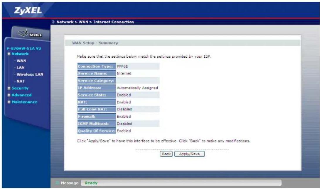
- Click Apply/Save
IGMP Multicast Proxy
IP Multicast Introduction
• What is the IP Multicast?
Traditionally, the IP packets are transmitted in two ways: unicast or broadcast. Multicast is a third way to deliver the IP packets to a group of hosts. Host groups are identified by the class D IP addresses, i.e., those with "1110" as their higher-order bits. In dotted decimal notation, host group addresses range from 224.0.0.0 to 239.255.255.255. Among them, 224.0.0.1 is assigned to the permanent IP hosts group, and 224.0.0.2 is assigned to the multicast routers group.
The IGMP (Internet Group Management Protocol) is the protocol used to support multicast groups. The latest version is version 2 (See RFC2236). The IP hosts use the IGMP to report their multicast group membership to any immediate-neighbor multicast routers, so the multicast routers can decide if a multicast packet needs to be forwarded. At the start-up, the Prestige queries all directly connect networks to gather group membership.
After that, the CPE updates the information by periodic queries. The device implementation of IGMP is also compatible with version 1. The multicast setting can be turned on or off on the Ethernet and remote nodes.
IGMP Multicast Proxy Configuration
a. IGMP Multicast Proxy
- Go to Network > WAN > Internet Connection
- Select the WAN interface (IPoE or PPPoE) and click on Edit
- Go the page where IGMP Multicast Proxy shows
IGMP Multicast

Enable IGMP Multicast Proxy
Back Next
- Select "Enable" for IGMP Multicast
- Click Next till we can Apply/Save it
Protocol Based Scenario
Environment
flowchart
graph TD
    A["IPTV server"] --> B["L3 switch"]
    B --> C["VDSL switch"]
    C --> D["BRAS"]
    D --> E["Router"]
    E --> F["INTERNET"]
    C --> G["P-870HW-51aV2"]
    G --> H["STB"]
    H --> I["NB"]
    I --> J["TV"]
    K["Fiber<br>Cat 5e/6<br>Copper<br>AV cable"] --> B
    L["IPoE"] --> C
    M["PPoE"] --> C
    N["VDSL switch"] --> O["• Bridge mode<br>• Internet: VLAN ID =100<br>• IPTV: VLAN ID = 200<br>• ACL Rules classifying traffic<br>• VLAN tagging according to ACL rules<br>• VLAN untagged at all egress ports"]
    style A fill:#4CAF50,stroke:#333
    style B fill:#4CAF50,stroke:#333
    style C fill:#4CAF50,stroke:#333
    style D fill:#4CAF50,stroke:#333
    style E fill:#FFA500,stroke:#333
    style F fill:#FFA500,stroke:#333
    style G fill:#FFA500,stroke:#333
    style H fill:#FFA500,stroke:#333
    style I fill:#FFA500,stroke:#333
    style J fill:#FFA500,stroke:#333
    style K fill:#FFA500,stroke:#333
    style L fill:#FFA500,stroke:#333
    style M fill:#FFA500,stroke:#333
    style N fill:#FFA500,stroke:#333
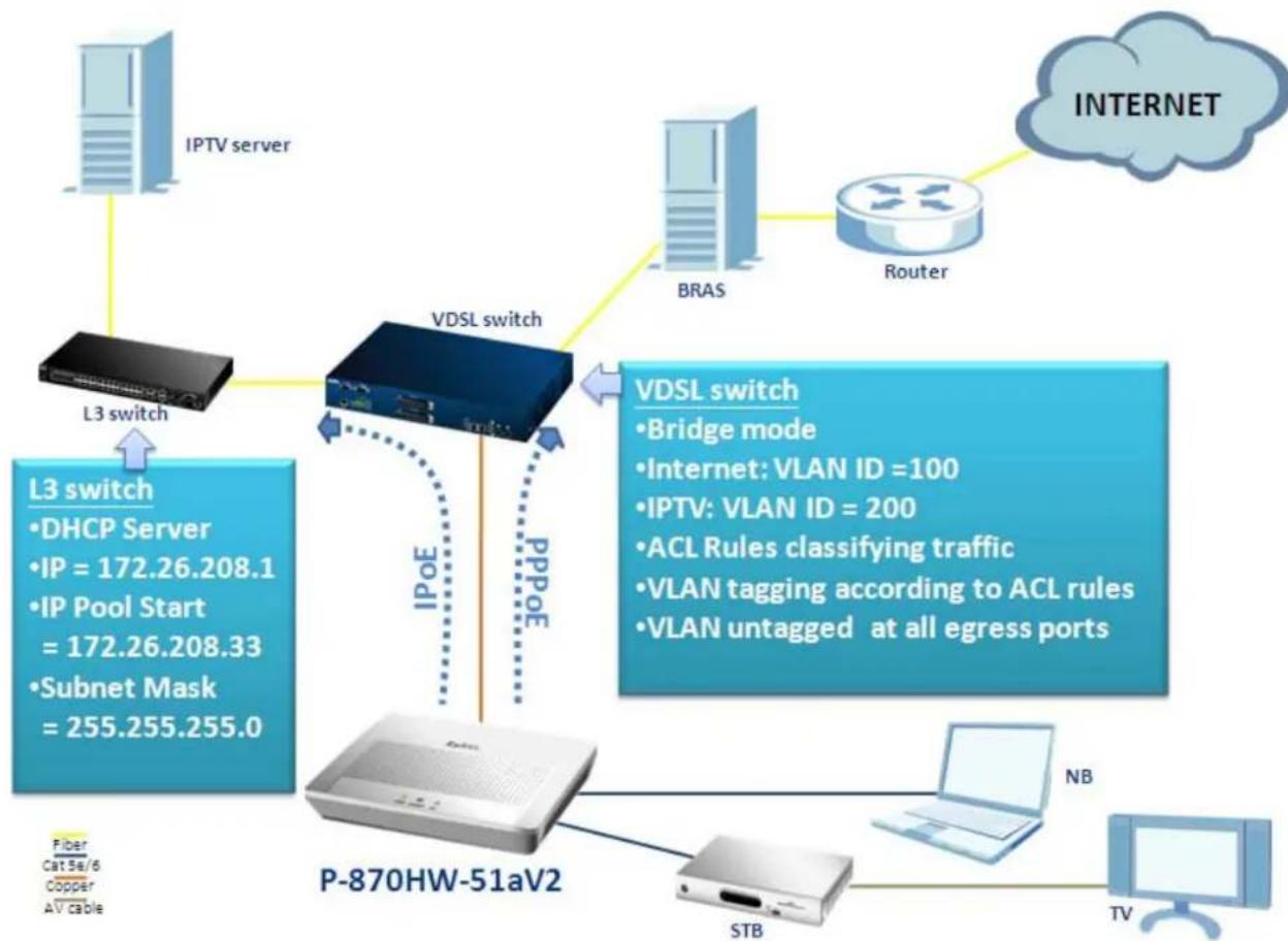
The Network structure of Central Office depends on the deployment of different ISP (Internet Service Provider) in different environments in different countries. One of the commonly known methods for separating different types of traffic is by classifying their transmitting protocols. In the case of the aforementioned diagram, the INTERNET traffic is encapsulated in the PPPoE and the IPTV traffic is encapsulated in the IPoE. The COE (VDSL switch) has the ability to distinguish those 2 traffics and assign the dedicated ACL rules to them. So, how should we configure the P-870HW-51aV2 to fit the aforementioned scenario? The following step-by-step procedure instructs us the method.
WAN Configuration
a. Internet Service
- Go to Network > WAN > Internet Connection.
- Click Add
- Select the Layer 2 interface for this service, e.g "ptm0/(0_0_1)"
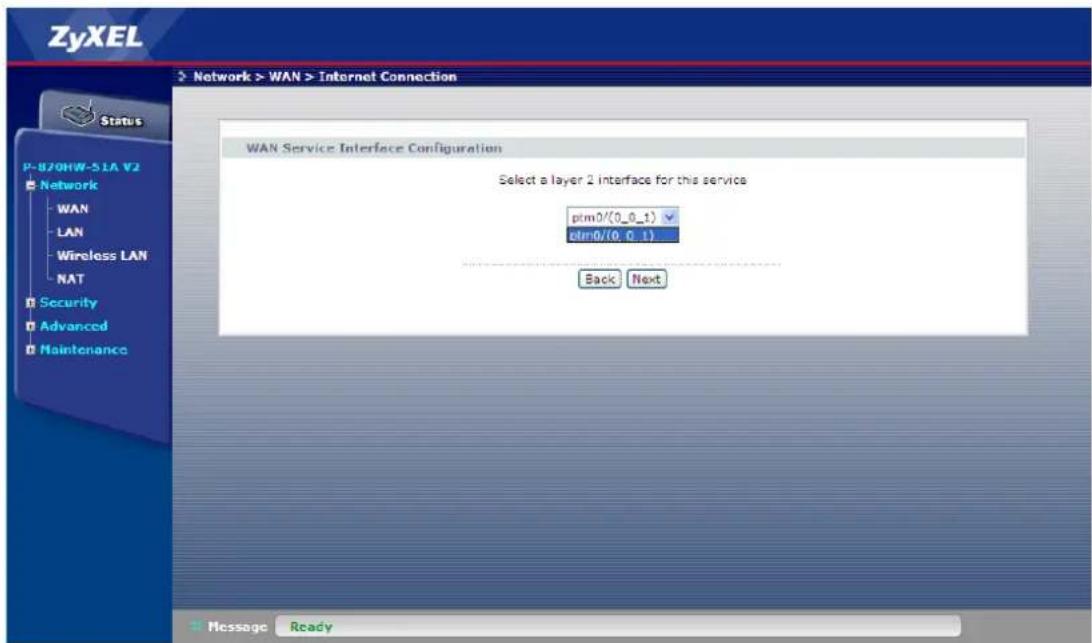
- Click Next
- Select the WAN service type, i.e. "PPP over Ethernet (PPPoE)"
- Enter the Service Description, e.g. "Internet"
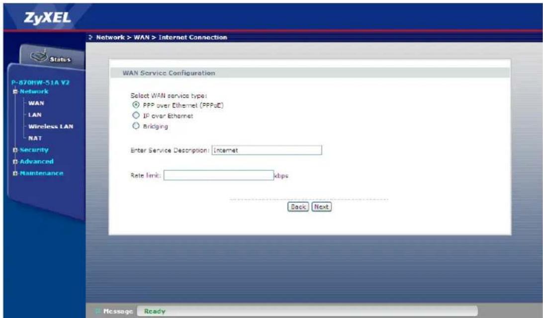
- Click Next
- Enter the PPP Username, e.g. "test@isp.net"
- Enter the PPP Password, e.g. "1234"
- Enter the PPPoE Service Name, e.g. "PPPoE"
- Select the Authentication Method to be "AUTO"
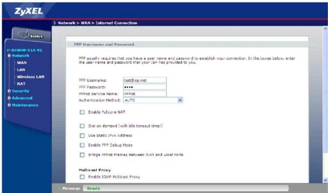
- Click Next
- Select the WAN Interface, e.g. "Internet/ppp0_1" for the default gateway
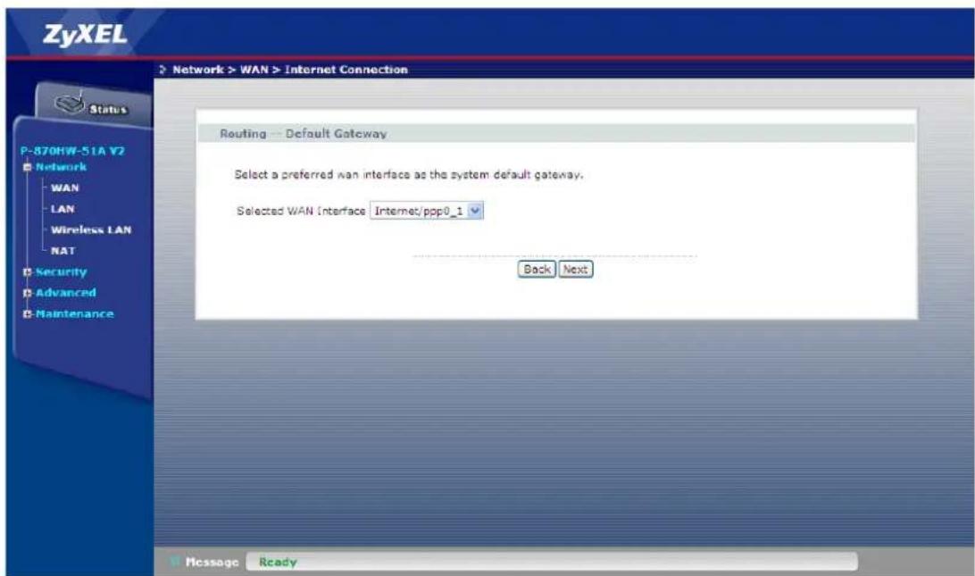
- Click Next
- Select Obtain DNS info from a WAN interface and select the interface
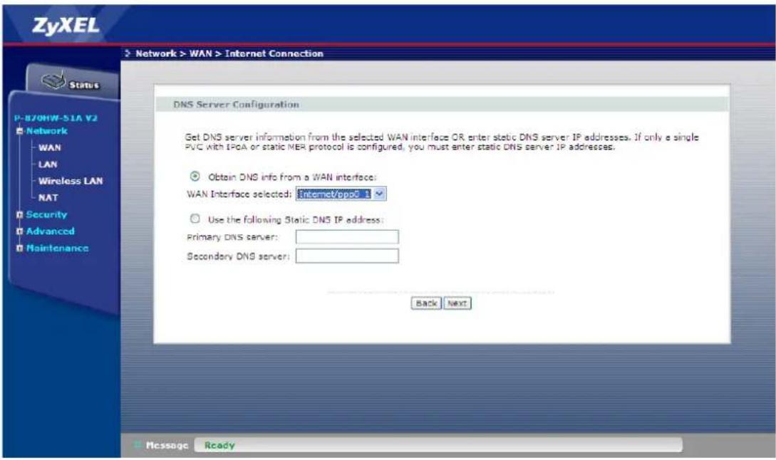
- Click Next
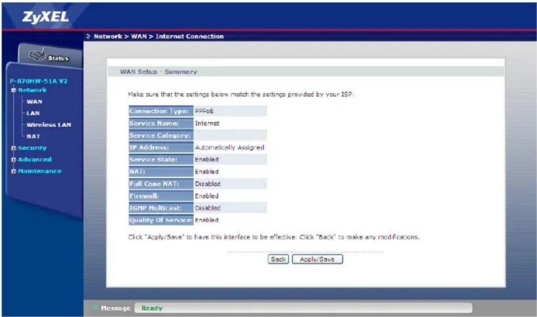
- Click Apply/Save
b. IPTV Service
- Go to Network > WAN > Internet Connection.
- Click Add
- Select the Layer 2 interface for this service, e.g "ptm0/(0_0_1)"
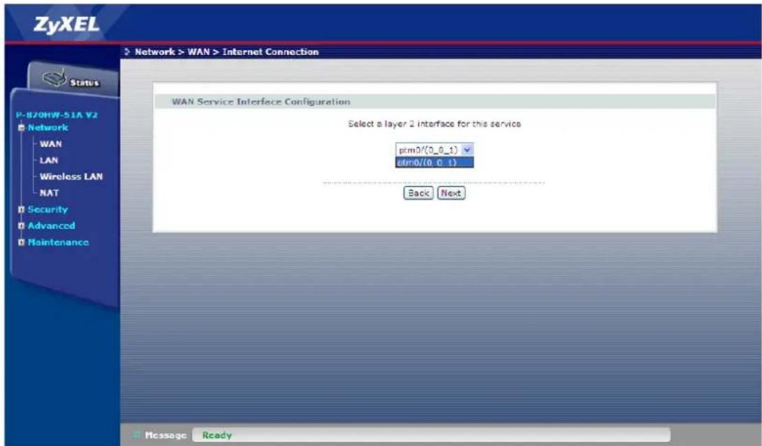
- Click Next
- Select the WAN service type, i.e. "IP over Ethernet"
- Enter the Service Description, e.g. "IPTV"
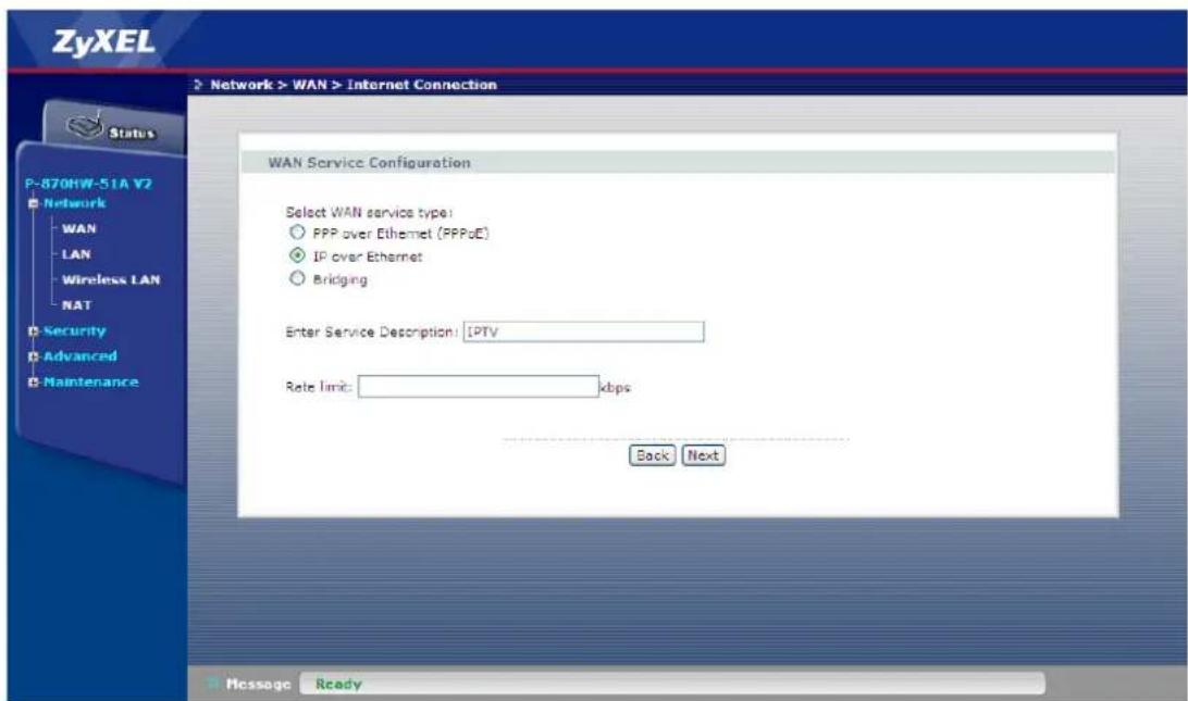
- Click Next
- Select Obtain an IP address automatically
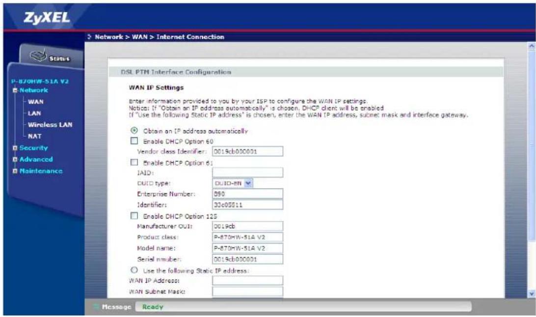
9. Click Next
10. Select Enable IGMP Multicast Proxy
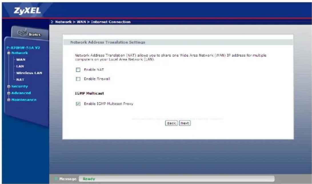
- Click Next
- Select the WAN Interface, e.g. "IPTV/ptm0_2" for the default gateway
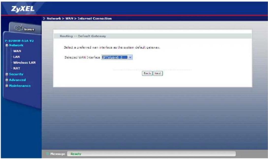
- Click Next
- Select Obtain DNS info from a WAN interface and select the interface
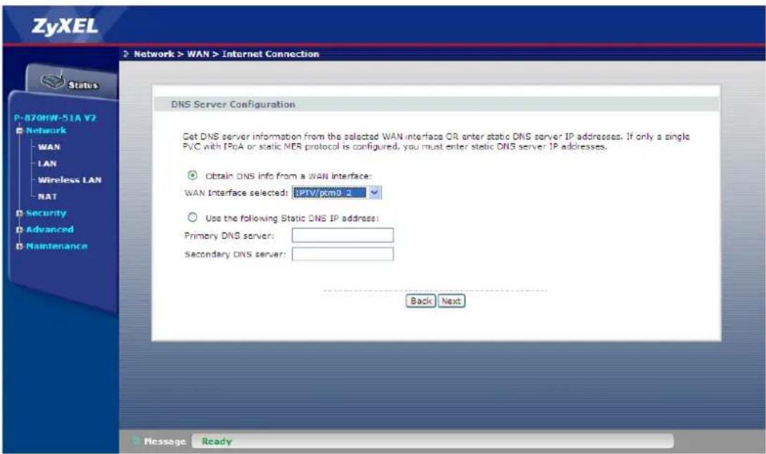
- Click Next
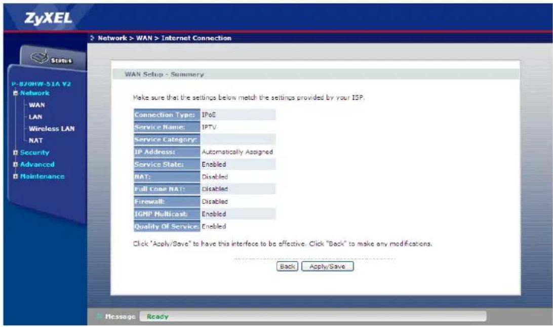
- Click Apply/Save
VLAN Based Scenario
Environment
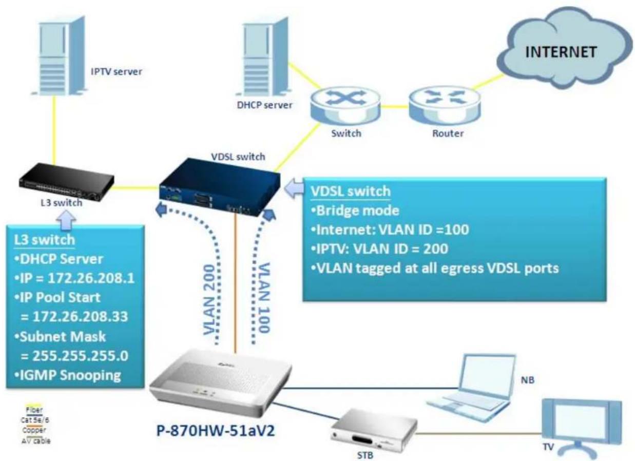
flowchart
graph TD
    A["IPTV server"] --> B["L3 switch"]
    C["DHCP server"] --> D["VDSL switch"]
    E["Switch"] --> D
    F["Router"] --> D
    G["P-870HW-51aV2"] --> H["STB"]
    H --> I["NB"]
    I --> J["TV"]
    K["INTERNET"] --> L["Switch"]
    L --> M["Router"]
    N["L3 switch"] --> O["L3 switch"]
    O --> P["IP = 172.26.208.1"]
    O --> Q["IP Pool Start = 172.26.208.33"]
    O --> R["Subnet Mask = 255.255.255.0"]
    O --> S["IGMP Snooping"]
    T["VDSL switch"] --> U["VLAN 200"]
    U --> V["VLAN 100"]
    V --> W["VDSL switch"]
    X["VDSL switch"] --> Y["• Bridge mode"]
    Y --> Z["• Internet: VLAN ID =100"]
    Y --> AA["• IPTV: VLAN ID = 200"]
    Y --> AB["• VLAN tagged at all egress VDSL ports"]
The Network structure of Central Office depends on the deployment of different ISP (Internet Service Provider) in different environments in different countries. One of the commonly known methods for separating different types of traffic is by classifying their VLAN ID. In the case of the aforementioned diagram, the INTERNET traffic is tagged with a VID=100 and the IPTV traffic is tagged with a VID=200. The COE (VDSL switch) receives the already VLAN tagged traffic from the CPE, and handles them according to their VID values. So how should we configure the P-870HW-51aV2 to fit the aforementioned scenario? The following step-by-step procedure instructs us the method.
WAN Configuration
a. INTERNET Service
- Go to Network > WAN > Layer 2 Interface
- Remove the default ptm0 Interface
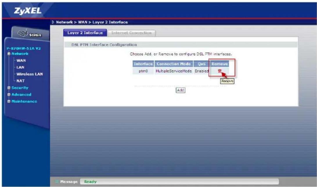
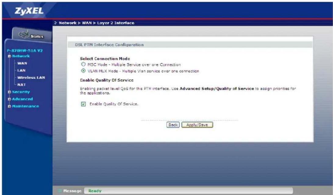
- Click Add
- Select VLAN MUX mode
- Select Enable Quality of Service
- Click Apply/Save
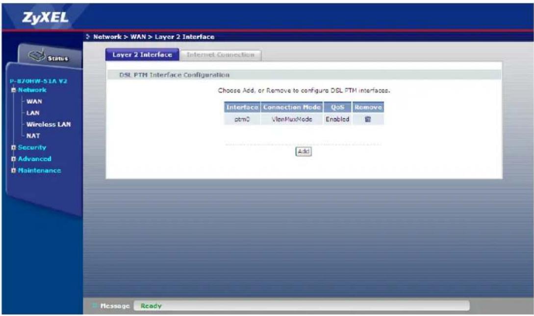
- Go to Network > WAN > Internet Connection.
- Click Add
- Select the Layer 2 interface for this service, e.g "ptm0/(0_0_1)"
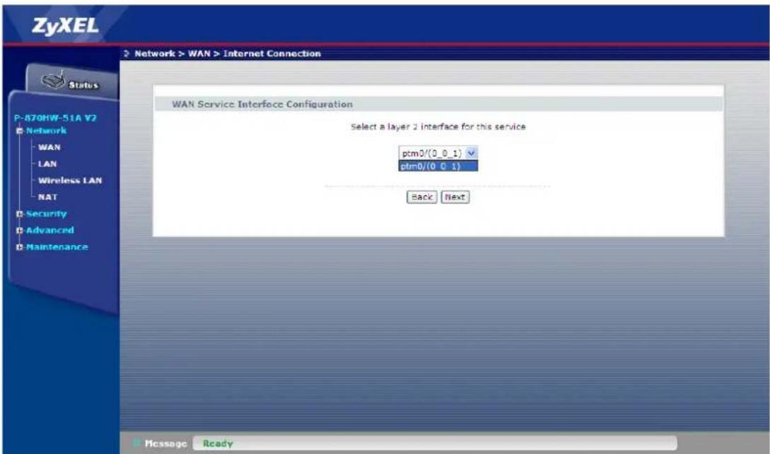
- Click Next
- Select the WAN service type, i.e. "IP over Ethernet"
- Enter the Service Description, e.g. "Internet"
- Check the Tag VLAN ID for egress packets box
- Enter "0" for Enter 802.1P Priority
- Enter "100" for Enter 802.1Q VLAN ID
![ZyXEL Network > WAN > Internet Connection Status P-870HW-51A V2 Network WAN LAN Wireless LAN NAT Security Advanced Maintenance WAN Service Configuration Select WAN service type: PPP over Ethernet (PPPoE) IP over Ethernet Bridging Enter Service Description: Internet Rate limit: kbps Tag VLAN ID for egress packets Enter 802.1P Priority [0-7]: 0 Enter 802.1Q VLAN ID [1-4094]: 100 Back Next Message Ready](/content/2026/05/834580/images/d59c2444760e3759ab418725622385b11fb56a279a1a7616861e68ad8125b0ae.jpg)
- Click Next
- Select Obtain an IP address automatically
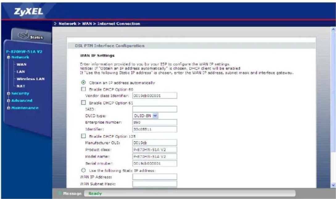
- Click Next
- Select Enable NAT
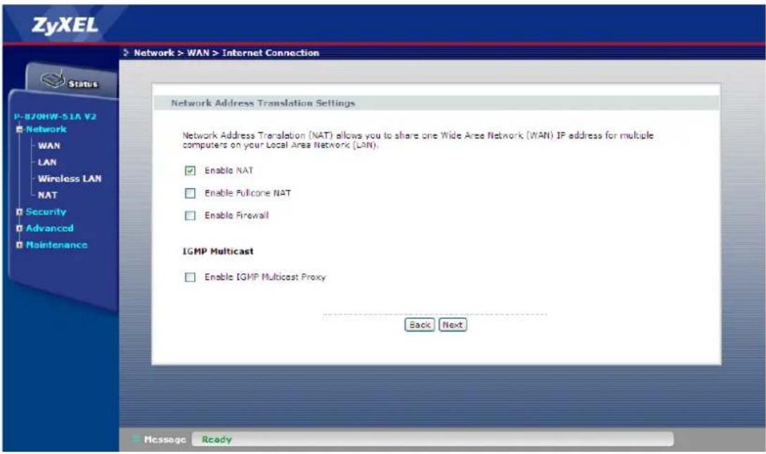
- Click Next
- Select the WAN Interface, e.g. "Internet.100/ptm0.100" for the default gateway
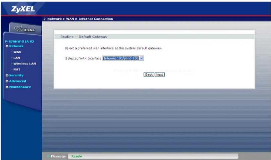
- Click Next
- Select Obtain DNS info from a WAN interface and select the interface
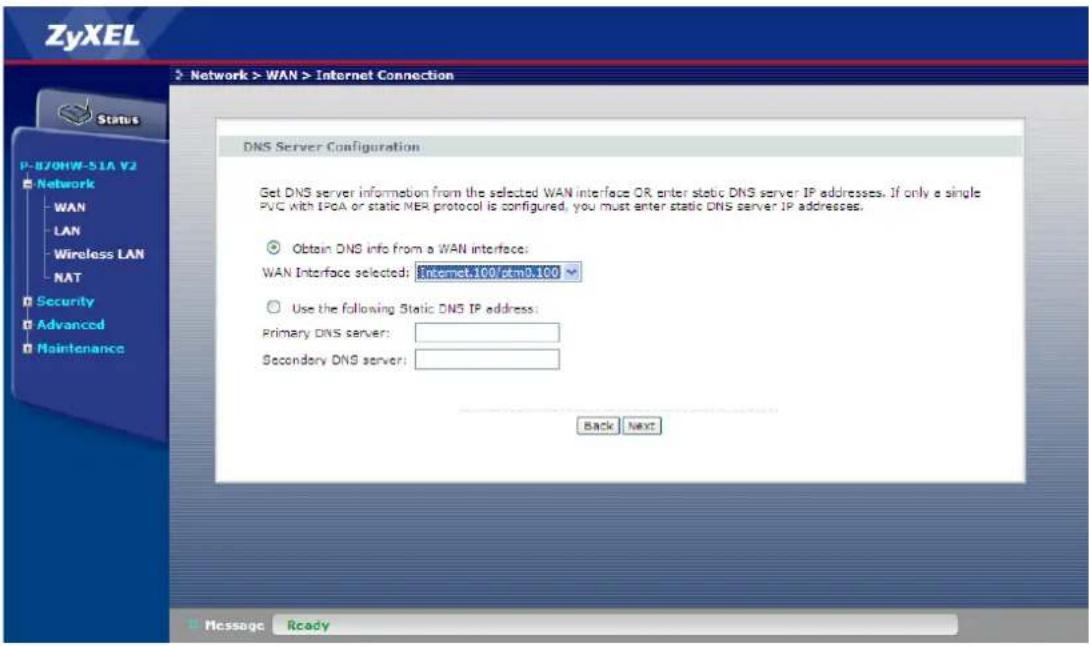
- Click Next
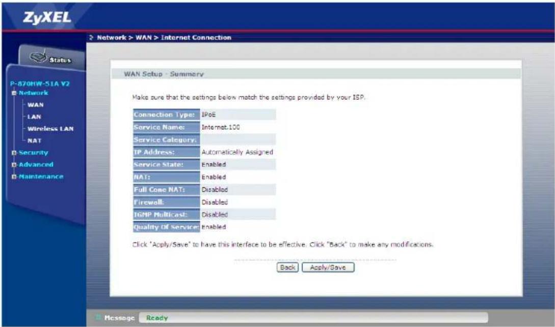
- Click Apply/Save
b. IPTV Service
- Go to Network > WAN > Internet Connection.
- Click Add
- Select the Layer 2 interface for this service, e.g "ptm0/(0_0_1)"
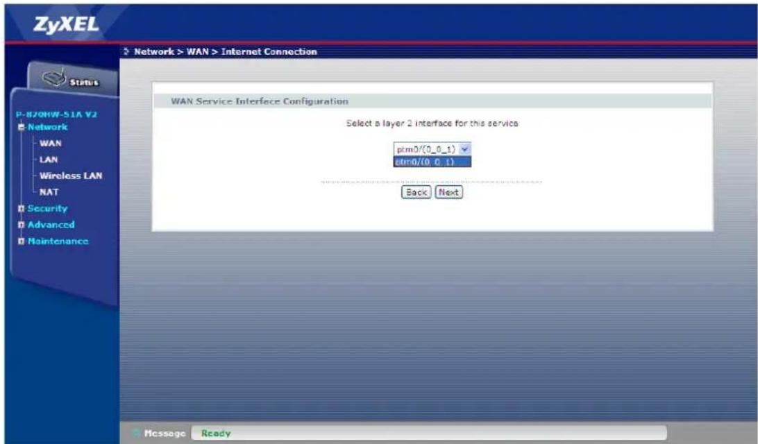
- Click Next
- Select the WAN service type, i.e. "IP over Ethernet"
- Enter the Service Description, e.g. "IPTV"
- Check the Tag VLAN ID for egress packets box
- Enter "5" for Enter 802.1P Priority
- Enter "200" for Enter 802.1Q VLAN ID
![ZyXEL Network > WAN > Internet Connection Status P-870HW-51A V2 Network WAN LAN Wireless LAN NAT Security Advanced Maintenance WAN Service Configuration Select WAN service type: PPP over Ethernet (PPPoE) IP over Ethernet Bridging Enter Service Description: IPTV Rate limit: dips Tag VLAN ID for egress packets Enter 802.1P Priority [0-7]: 5 Enter 802.1Q VLAN ID [1-4094]: 200 Back Next Message Ready](/content/2026/05/834580/images/342c2dd2a607580e65a7e08e00b742e66704c45f065863e7765ac9e1b7b0c1dc.jpg)
- Click Next
- Select Obtain an IP address automatically
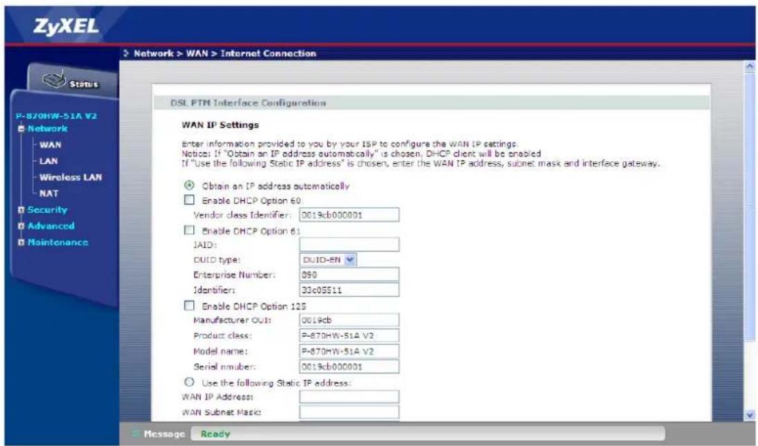
- Click Next
- Select Enable IGMP Multicast Proxy
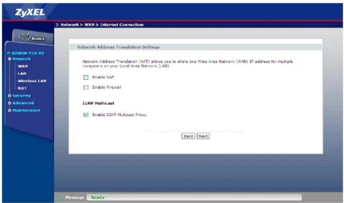
- Click Next
- Select the WAN Interface, e.g. "IPTV.200/ptm0.200" for the default gateway
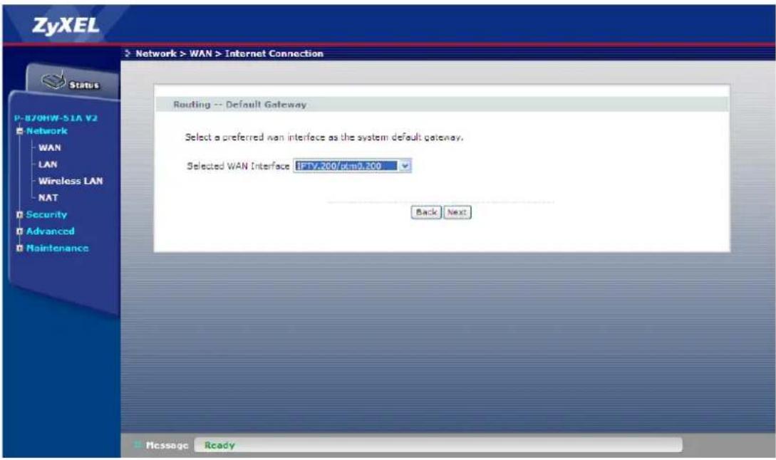
- Click Next
- Select Obtain DNS info from a WAN interface and select the interface
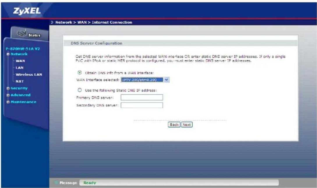
- Click Next
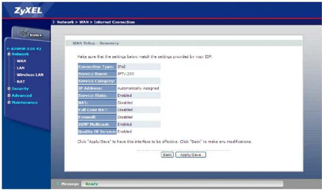
- Click Apply/Save
Quality of Service
Environment
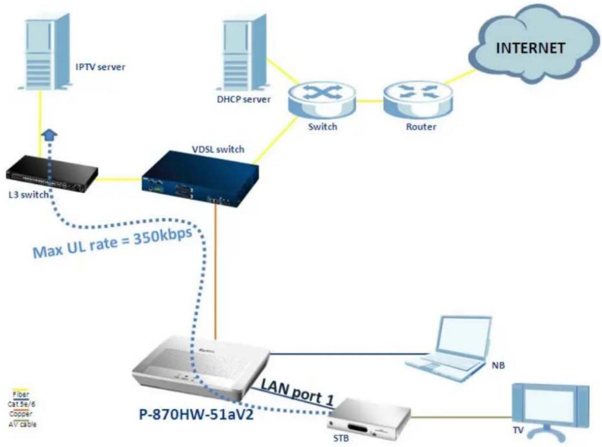
flowchart
graph TD
    A["IPTV server"] -->|Max UL rate = 350kbps| B["VDSL switch"]
    C["DHCP server"] -->|Max UL rate = 350kbps| D["Switch"]
    E["Router"] -->|Max UL rate = 350kbps| D
    F["Internet"] -->|Max UL rate = 350kbps| G["Switch"]
    H["L3 switch"] --> B
    I["P-870HW-51aV2"] --> J["LAN port 1"]
    K["STB"] --> J
    L["NB"] --> J
    M["TV"] --> J
    N["Fiber Cat SE/6 Copper AV cable"] --> B
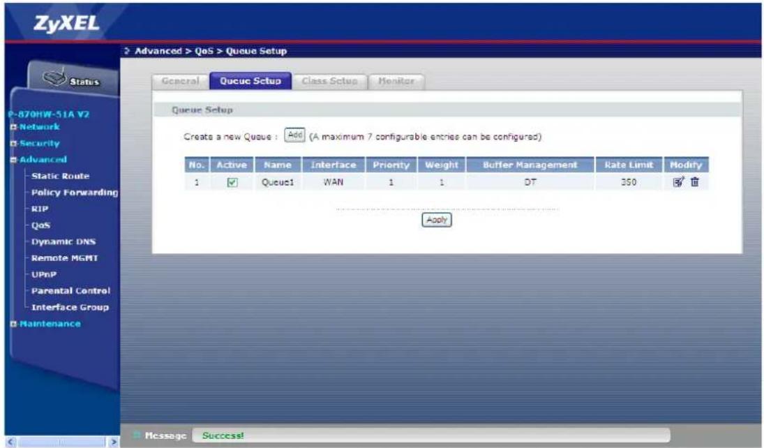
The “Quality of Service” feature in P-870HW-51aV2 has the ability to assign different task in accordance with the chosen type of traffic. In the case of the aforementioned diagram, we would like to limit the maximum upload rate of the IPTV service to 350 kbps. So how should we configure the P-870HW-51aV2 to fit the aforementioned scenario? The following step-by-step procedure instructs us the method.
QoS configuration
a. Enable QoS
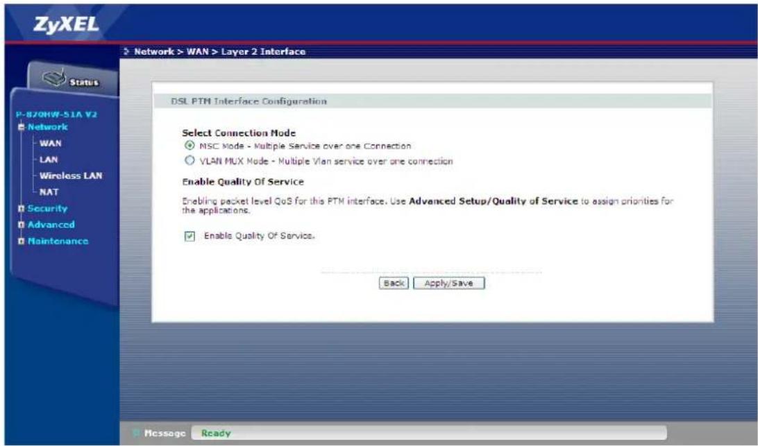
- Make sure that QoS is enabled in Network > WAN > Layer2 Interface
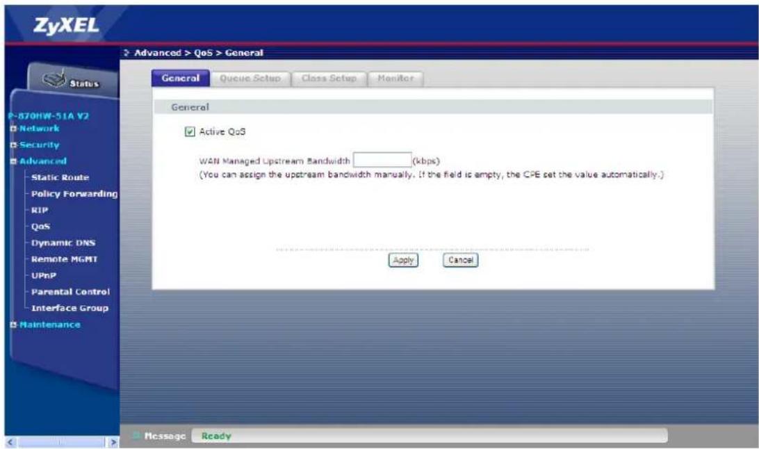
- Go to Advanced > QoS > General
- Check the Active QoS box.
- Go to Advanced > QoS > Queue Setup.
- Click Add.
- Check the Active box
-
Input the Name, e.g. "Queue1"
-
Select the Interface
- Select the Priority
- Select the Weight
- Input the Rate Limit, e.g. "350"
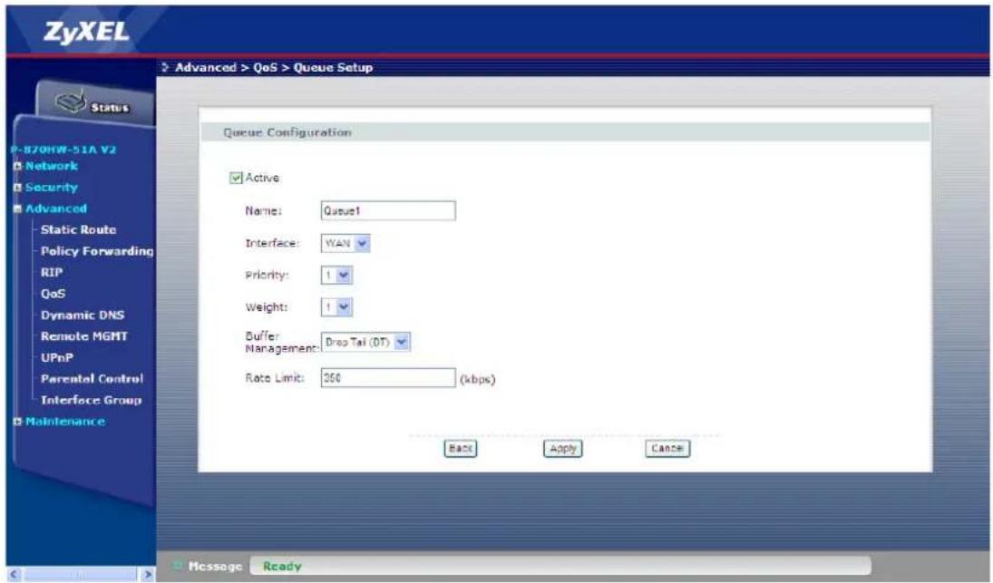
- Click Apply
b. Configure the Video traffic.
- Go to Advanced > QoS > Class Setup
- Select the Active box
- Select the Classification Order
- Select the Forward To Interface
- Select the To Queue as Queue1
- Select the From Interface, e.g. "LAN1"
- Select Ether Type, e.g. "IP (0x800)
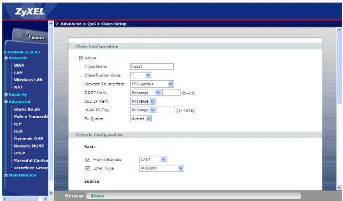
- Click Apply
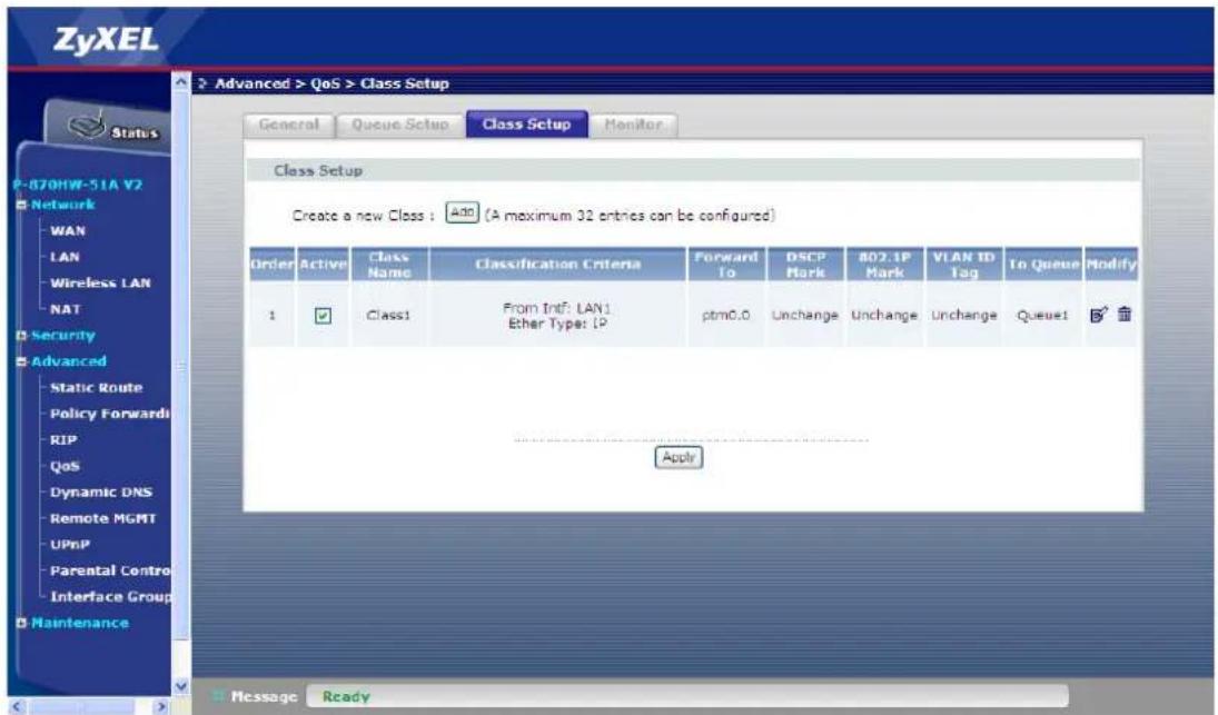
- Check if the Classification is created accordingly
TR069 – Remote Firmware Upgrade
Environment
flowchart
graph TD
    A["IPTV server"] --> B["L3 switch"]
    C["DHCP server"] --> D["VDSL switch"]
    E["Switch"] --> D
    F["Router"] --> D
    G["INTERNET"] --> H["TR069 ACS Server"]
    D --> I["P-870HW-51aV2"]
    I --> J["STB"]
    J --> K["NB"]
    K --> L["TV"]
    style A fill:#cce5ff,stroke:#333
    style C fill:#cce5ff,stroke:#333
    style E fill:#cce5ff,stroke:#333
    style G fill:#cce5ff,stroke:#333
    style I fill:#e6f3ff,stroke:#333
    style J fill:#e6f3ff,stroke:#333
    style K fill:#e6f3ff,stroke:#333
    style L fill:#e6f3ff,stroke:#333
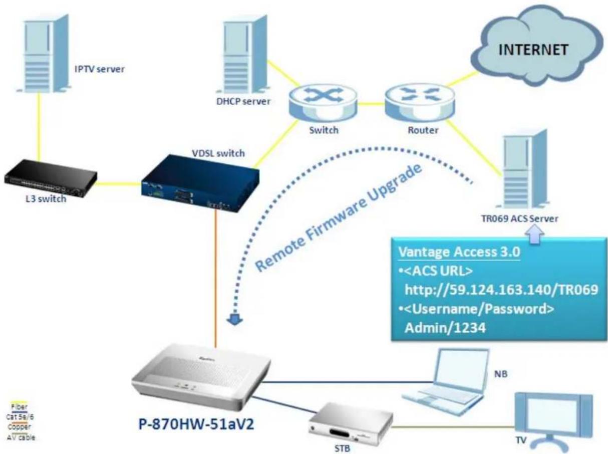
The P-870HW-51a v2 provides the TR-069 remote management feature; it could speed up the deployment of CPEs and ease our supporting costs. It can also help the VDSL ISP (Internet Service Provider) to reduce operation effort as well as enhance customer satisfaction. In the case of the aforementioned diagram, the TR069 ACS server remote upgrades the firmware of CPE. So how should we configure the P-870HW-51aV2 to fit the aforementioned scenario? The following step-by-step procedure instructs us the method.
Note: This document uses a ZyXEL ACS server, Vantage Access 3.0, as a reference.
TR069 Configuration
a. Configure the required TR069 parameters for the ACS server.
- Go to Advanced > Remote MGNT > TR069 Auto-Configure
- Check the Inform box to "Enable"
- Enter the Inform Interval, e.g. "30" seconds.
- Enter the ACS URL, e.g. "http://59.124.163.140/TR069".
- Enter the ACS User Name, e.g. "admin".
- Enter the ACS Password, e.g. "1234".
- Select the WAN Interface used by TR-069 client, e.g. "Any_WAN".
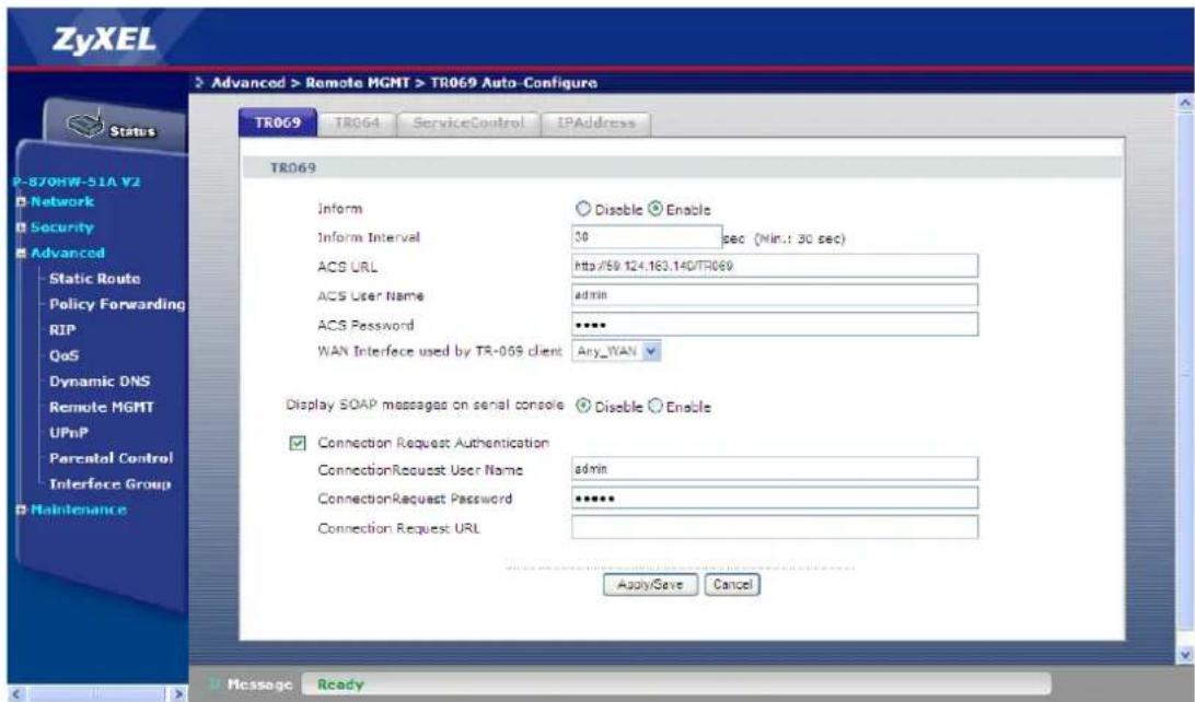
- Click Apply/Save
NAT Portforwarding
NAT/Multi-NAT Introduction
• What is Multi-NAT?
The NAT (Network Address Translation-NAT RFC 1631) is the translation of an Internet Protocol address used within one network to a different IP address known within another network. One network is designated as the inside network and the other is the outside. Typically, one company maps its local inside network addresses to one or more global outside IP addresses and "unmaps" the global IP addresses on the incoming packets back into local IP addresses. The IP addresses for NAT can be either fixed or dynamically assigned by the ISP. In addition, you can designate servers, e.g., a Web server and a Telnet server, on your local network and make them accessible to the outside world. If you do not define any servers, the NAT offers the additional benefit of firewall protection. In such case, all incoming connections to your network will be filtered out by the CPE, thus preventing intruders from probing your network.
For more information on the IP address translation, please refer to RFC 1631, The IP Network Address Translator (NAT).
• How NAT works?
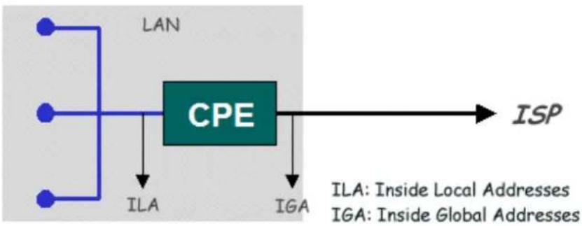
If we define the local IP addresses as the Internal Local Addresses (ILA) and the global IP addresses as the Inside Global Address (IGA), see the following figure. The term 'inside' refers to the set of networks that are subject to translation. The NAT operates by mapping the ILA to the IGA required for communication with hosts on other networks. It replaces the original IP source address (and TCP or UDP source port numbers) and then forwards each packet to the Internet ISP, thus making them appear as if they came from the NAT system itself (e.g., the CPE router). The CPE keeps track of the original addresses and port numbers, so the incoming reply packets can have their original values restored.
flowchart
graph LR
    A["LAN"] --> B["CPE"]
    B --> C["ISP"]
    D["ILA"] --> B
    E["IGA"] --> B
    style B fill:#99ccff,stroke:#333
Figure1: Local/Global IP Addresses
- NAT Mapping Types
The NAT supports five types of IP/port mapping. They are:
1. One to One
In One-to-One mode, the Prestige maps one ILA to one IGA.
2. Many to One
In Many-to-One mode, the CPE maps multiple ILAs to one IGA.
3. Many to Many Overload
In Many-to-Many Overload mode, the CPE maps the multiple ILAs to shared IGA.
4. Many to Many No Overload
In Many-to-Many No Overload mode, the CPE maps each ILA to unique IGA.
• Server (DMZ host)
In Server mode (DMZ host), the CPE maps multiple inside servers to one global IP address. This allows us to specify multiple servers of different types behind the NAT for outside access. Note: If you want to map each server to one unique IGA, please use the One-to-One mode.
The following table summarizes these types.
| NAT Type | IP Mapping | Mapping Direction |
| One-to-One | ILA1<---->IGA1 | Both |
| Many-to-One | ILA1---->IGA1ILA2---->IGA1... | Outgoing |
| Many-to-Many Overload | ILA1---->IGA1ILA2---->IGA2ILA3---->IGA1ILA4---->IGA2... | Outgoing |
| Many-to-Many Overload (Allocate by Connections) | ILA1---->IGA1ILA2---->IGA3ILA3---->IGA2ILA4---->IGA4... | Outgoing |
| Server | Server 1 IP<----IGA1Server 2 IP<----IGA1 | Incoming |
• Port numbers for some services:
| Service | Port Number |
| FTP 21 | |
| Telnet 23 | |
| SMTP 25 | |
| DNS (Domain Name Server) | 53 |
| www-http (Web) | 80 |
Environment
flowchart
graph TD
    A["IPTV server"] --> B["L3 switch"]
    B --> C["VDSL switch"]
    C --> D["P-870HW-51aV2"]
    D --> E["FTP server"]
    E --> F["Router"]
    F --> G["Notebook"]
    G --> H["Internet"]
    G --> I["MB"]
    G --> J["PC"]
    G --> K["PC"]
    G --> L["PC"]
    style A fill:#cce5ff,stroke:#333
    style B fill:#cce5ff,stroke:#333
    style C fill:#99ccff,stroke:#333
    style D fill:#66ccff,stroke:#333
    style E fill:#99ccff,stroke:#333
    style F fill:#99ccff,stroke:#333
    style G fill:#99ccff,stroke:#333
    style H fill:#e6f7ff,stroke:#333
    style I fill:#e6f7ff,stroke:#333
    style J fill:#e6f7ff,stroke:#333
    style K fill:#e6f7ff,stroke:#333
    style L fill:#e6f7ff,stroke:#333
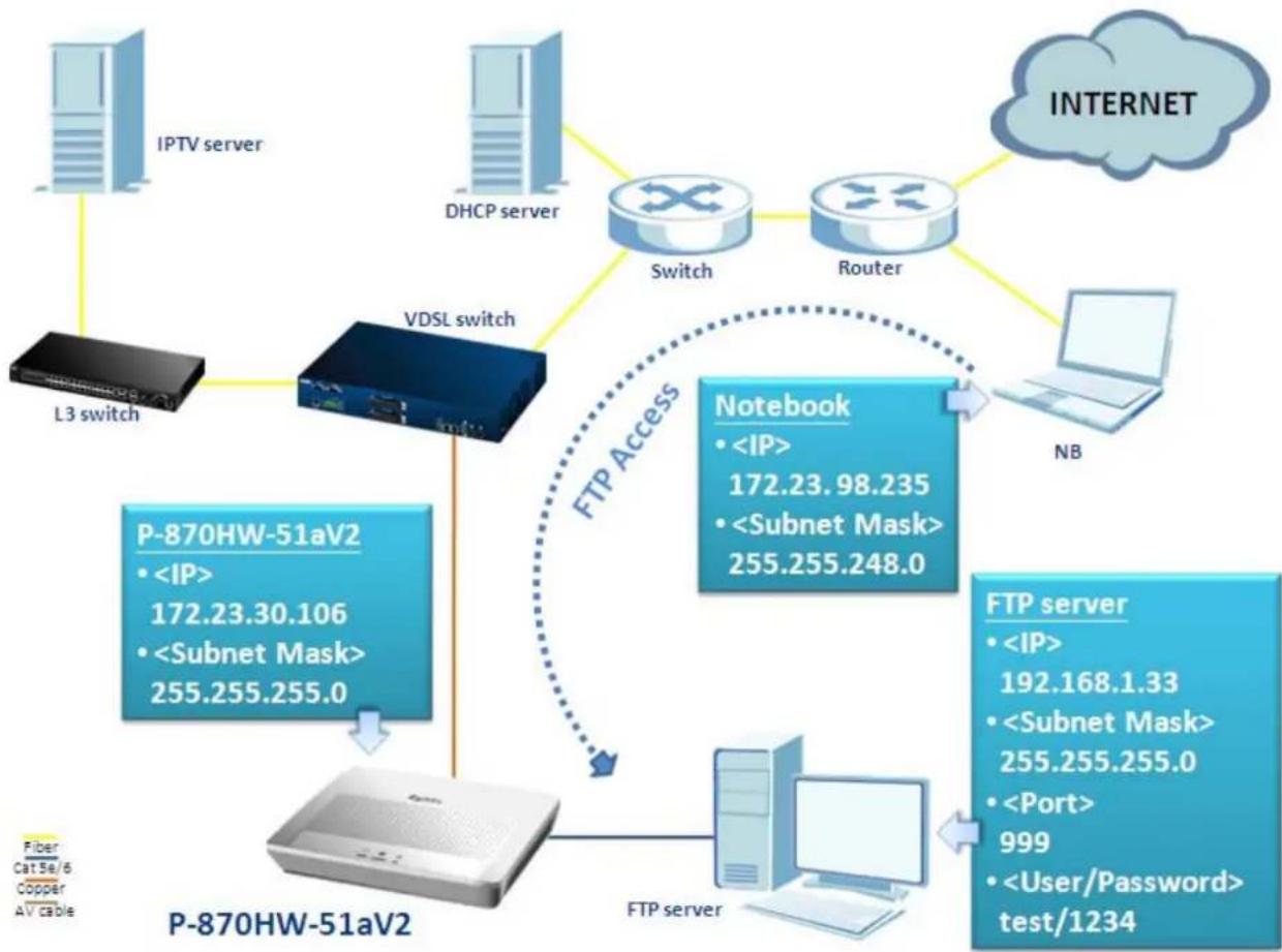
The NAT provides system administrators an easy solution to create a private IP network for security and IP management. Powered by NAT technology, the P-870HW-51aV2 supports complete the NAT mapping and most popular Internet multimedia applications. This feature is the best described with the NAT port forwarding feature implemented in the CPE. In the case of the above diagram, we have a FTP server installed behind the CPE with an IP assigned by the local DHCP server (192.168.1.33). How should we configure the P-870HW-51aV2, so that the notebook at the WAN site can access the FTP server? The following step-by-step procedure instructs us the method.
PS: Make sure that NAT is enabled in the WAN interface.
Port Forwarding Configuration
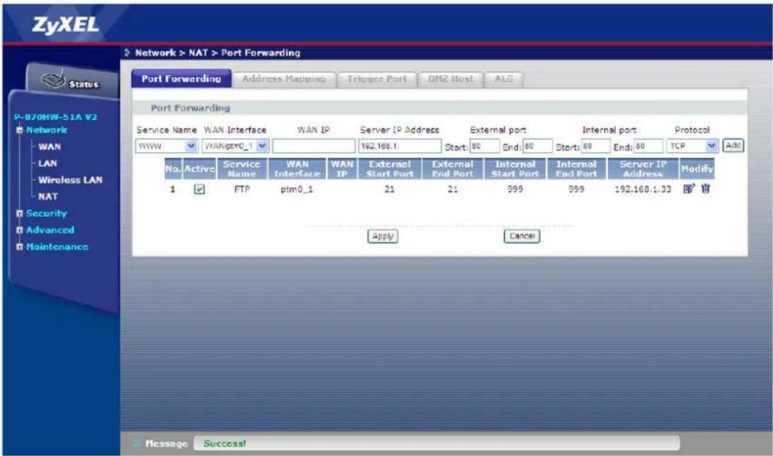
a. Create a port forwarding rule for the FTP server.
- Go to Network > NAT > Port Forwarding.
- Select the Service Name, e.g. "FTP".
- Select the WAN Interface, e.g. "WAN/ptm0_1".
- Enter the Server IP Address, e.g. "192.168.1.33".
- Enter the External port Start, e.g. "21".
- Enter the External port End, e.g. "21".
- Enter the Internal port Start, e.g. "999".
- Enter the Internal port End, e.g. "999".
- Select the Protocol, e.g. "TCP".
- Click Add.
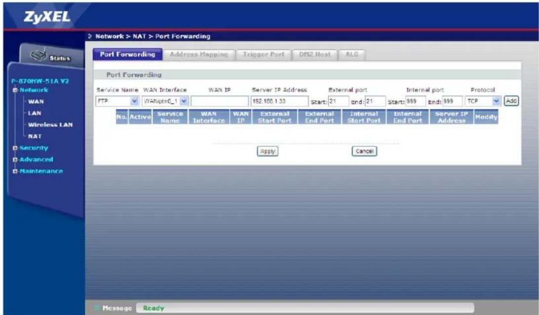
A warning message as followed will pop up:
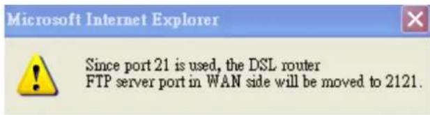
This phenomenon is normal, because the CPE itself can be accessed by the FTP, which the port is also 21. Since we are creating a new rule using port 21, the default
port number of the CPE's FTP server port will automatically be moved to 2121.
A new port forwarding rule is now created.
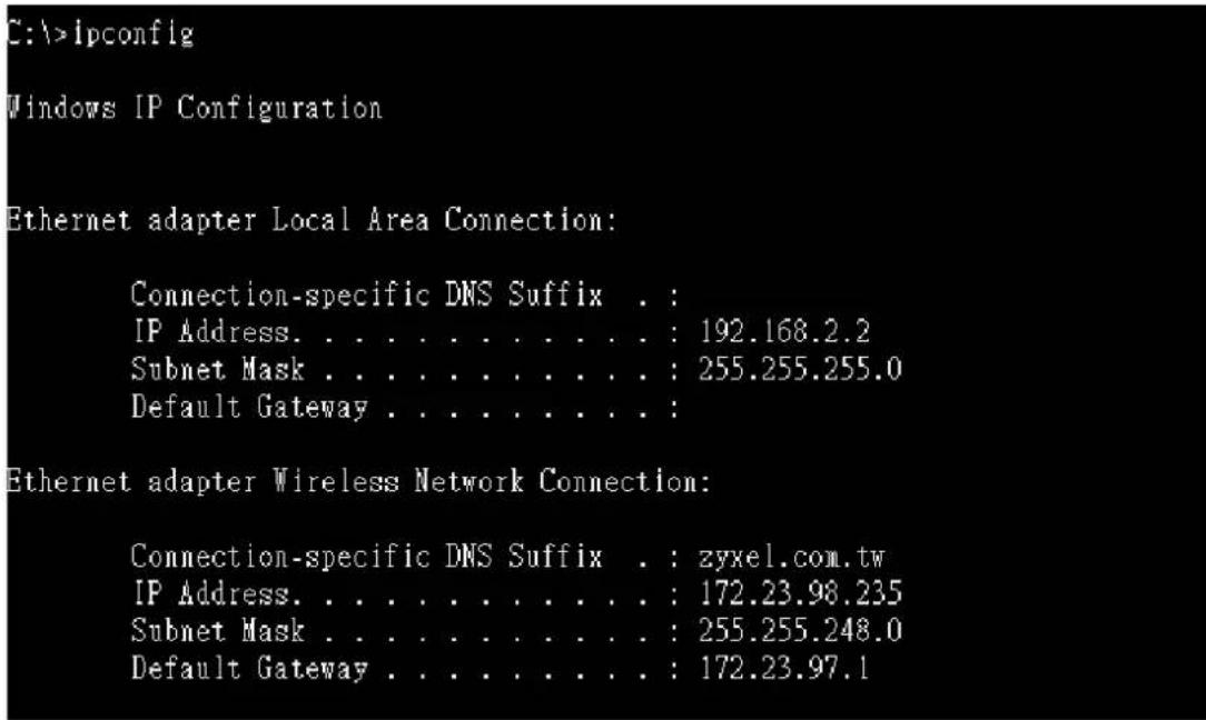
Show the IP configuration of notebook:
Use the notebook to access the FTP server with IP = 172.23.30.106.
C:\>ftp 172.23.30.106
Connected to 172.23.30.106.
220 FTP Server 2.0 Ready.
User (172.23.30.106:(none)): test
331 User name okay, need password.
Password:
230 User logged in
ftp>
Show the history log of FTP server.
2009/01/11 [16:11] Server Online - 192.168.1.33
2009/1/11 [16:11] (00352) 172.23.98.235> User connecting from 172.23.98.235
2009/1/11 [16:11] (00352) 172.23.98.235> USER test
2009/1/11 [16:11] (00352) test> 331 User name okay, need password.
2009/1/11 [16:11] (00352) test> PASS *****
2009/1/11 [16:11] (00352) test> 230 User logged in
We can see that the client (notebook with IP = 172.23.98.235) is in fact logged into the FTP server.
DMZ Host Configuration
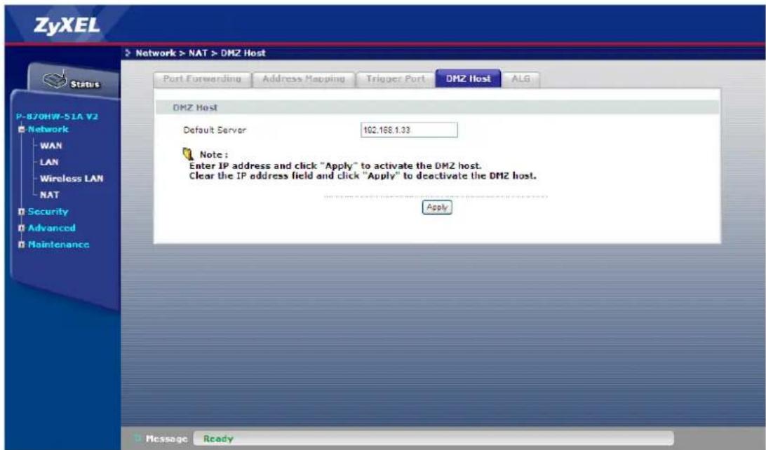
If we enable the DMZ host, it will open up all the internal ports to the dedicated Server IP (in this case, IP = 192.168.1.33) allowing client at the WAN side to access the FTP server via port forwarding.
a. Create a DMZ host.
- Go to Network > NAT > DMZ host.
- Enter the IP of the Default Server, e.g. "192.168.1.33".
- Click Save.
Use the notebook to access the FTP server with IP = 172.23.30.106.
C:\>ftp 172.23.30.106
Connected to 172.23.30.106.
220 FTP Server 2.0 Ready.
User (172.23.30.106:(none)): test
331 User name okay, need password.
Password:
230 User logged in
ftp>
Show the history log of FTP server.
2009/01/11 [16:37] Server Online - 192.168.1.33
2009/1/11 [16:37] (00348) 172.23.98.235 User connecting from 172.23.98.235
2009/1/11 [16:37] (00348) 172.23.98.235> USER test
2009/1/11 [16:37] (00348) test> 331 User name okay, need password.
2009/1/11 [16:37] (00348) test> PASS *****
2009/1/11 [16:37] (00348) test> 230 User logged in
We can see that the client (notebook with IP = 172.23.98.235) is in fact logged into the FTP server.
IP Filter
Environment
flowchart
graph TD
    A["IPTV server"] --> B["L3 switch"]
    C["DHCP server"] --> D["VDSL switch"]
    D --> E["Switch"]
    D --> F["Router"]
    G["Notebook"] --> H["<IP> 172.23.98.235<br><Subnet Mask> 255.255.248.0"]
    H --> I["Denial of Service"]
    I --> J["P-870HW-51aV2<br>• <IP> 172.23.30.106<br>• <Subnet Mask> 255.255.255.0"]
    J --> K["PC"]
    L["PC"] --> M["P-870HW-51aV2"]
    style J fill:#4CAF50,stroke:#333
    style K fill:#FFA500,stroke:#333
    style M fill:#FFA500,stroke:#333
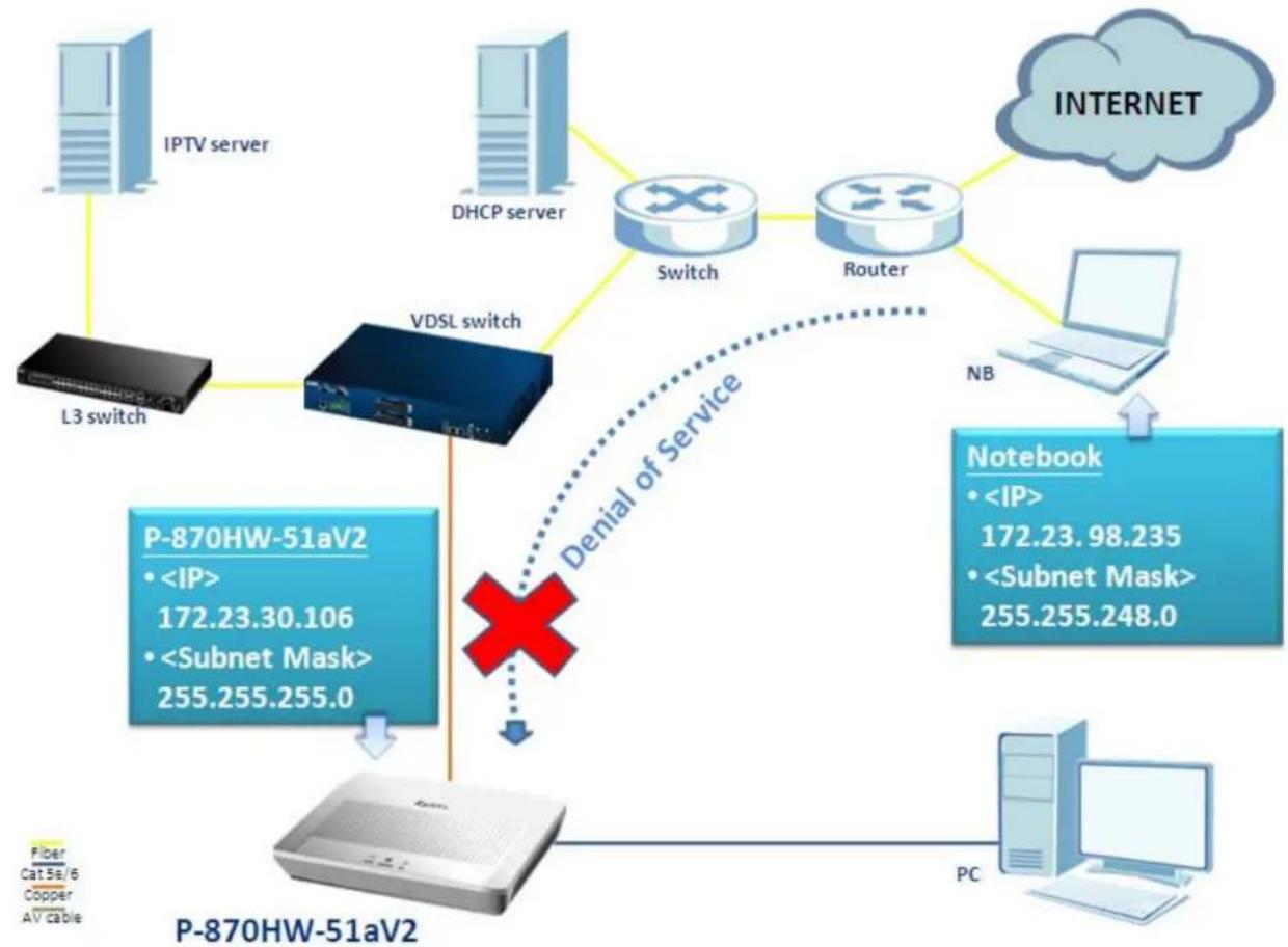
The P-870HW-51aV2 has stateful packet Inspection and Denial of service (DoS) function; it provides the first line of defense against hackers, network intruders and other hazardous threats. In the case of the above scenario, we would like to have the CPE filter all the traffic coming from notebook. How should we configure the P-870HW-51aV2 to fit this scenario? The following step-by-step procedure instructs us the method.
IP Filter Configuration
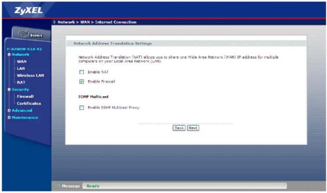
a. Make sure that Firewall is enable in the WAN
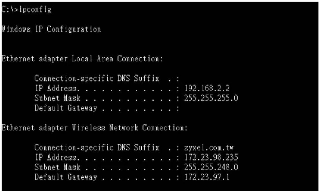
Show the IP configuration of notebook:
Use the notebook to ping the P-870HW-51aV2 with IP = 172.23.30.106.
C:\>ping 172.23.30.106
Pinging 172.23.30.106 with 32 bytes of data:
Request timed out.
Request timed out.
Request timed out.
Request timed out.

Ping statistics for 172.23.30.106:
    Packets: Sent = 4, Received = 0, Lost = 4 (100% loss),
C:\>
We can see that the ICMP packets do not come back; it is clearly that the ping request packets have all been filtered out by the CPE.
Configuration of Accepting Incoming Traffic
b. Configure the IP Filtering Setup.
- Go to Security > Firewall
- Check the Active Firewall box
- Click Add.
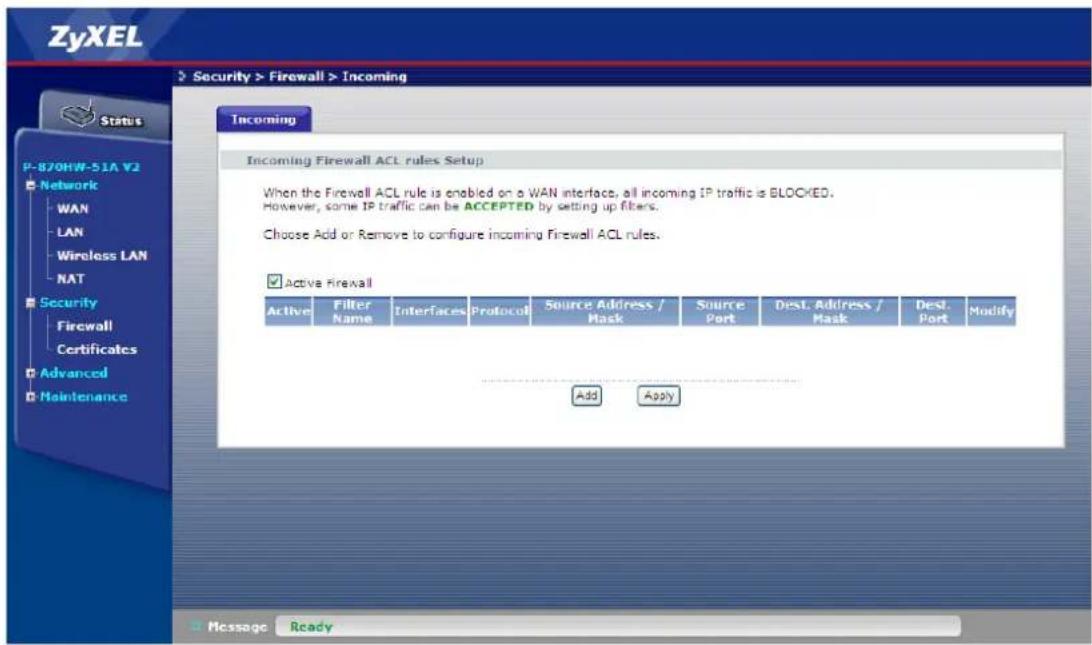
- Check the Active box
- Enter the Filter Name, e.g. "ping".
- Select the Protocol, e.g. "ICMP".
- Enter the Source IP address, e.g. "172.23.98.235".
- Enter the Source Subnet Mask, e.g. "255.255.248.0".
- Check the WAN Interface, e.g. "Internet/ptm0_1"
- Click Apply.
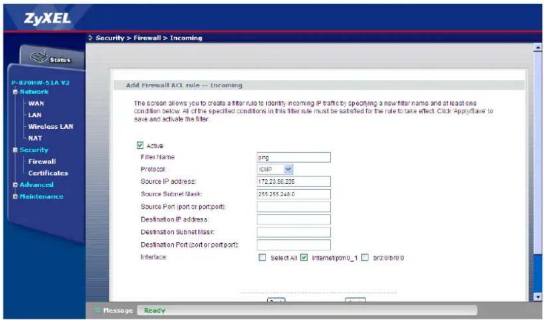
We can see the newly created rule as followed:
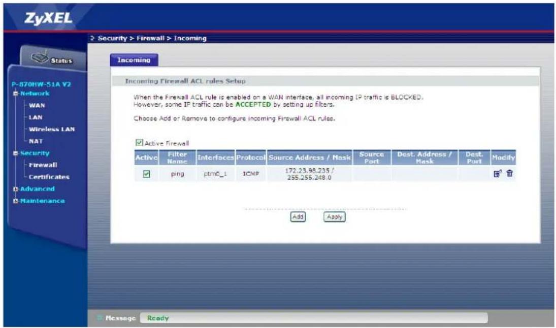
Use the notebook to ping the P-870HW-51aV2 with IP = 172.23.30.106.
C:\>ping 172.23.30.106
Pinging 172.23.30.106 with 32 bytes of data:
Reply from 172.23.30.106: bytes=32 time=153ms TTL=62
Reply from 172.23.30.106: bytes=32 time=44ms TTL=62
Reply from 172.23.30.106: bytes=32 time=17ms TTL=62
Reply from 172.23.30.106: bytes=32 time=36ms TTL=62
Ping statistics for 172.23.30.106:
    Packets: Sent = 4, Received = 4, Lost = 0 (0% loss),
Approximate round trip times in milli-seconds:
    Minimum = 17ms, Maximum = 153ms, Average = 62ms
C:\>
We can see that the ICMP request was successful, thus proving that the CPE is now accepting the traffic coming from notebook.
LAN Connection
IP Alias Introduction
• What is the IP Alias?
In a typical environment, a LAN router is required to connect two local networks. The device can connect three local networks to the ISP or a remote node; we call this function as 'IP Alias'. In this case, an internal router is not required. For example, the network manager can divide the local network into three networks and connect them to the Internet using CPE's single user account. See the following figure.
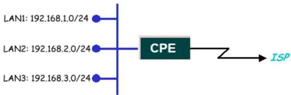
flowchart
graph LR
    A["LAN1: 192.168.1.0/24"] --> B["CPE"]
    C["LAN2: 192.168.2.0/24"] --> B
    D["LAN3: 192.168.3.0/24"] --> B
    B --> E["ISP"]
IP Alias connects three local networks to the Internet
The CPE supports three virtual LAN interfaces via its single physical Ethernet interface. As to the second and third networks, we call 'IP Alias 1' and 'IP Alias 2'.
IP Alias Configuration
a. IP Alias
- Go to Network > LAN > IP
- Check the Active IP Alias box.
- Enter the IP Address, e.g. "10.0.0.1".
- Enter the IP Subnet Mask, e.g. "255.255.255.0".
- Click Apply.
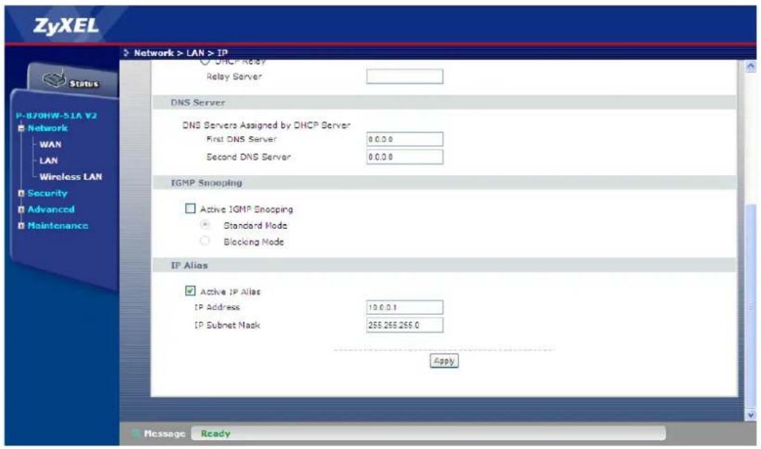
Maintenance Log
Internal Maintenance
The P-870HW-51aV2 has the ability to record the events happening in the CPE into a system log (according to the severity) and maintain this log in itself.
a. Activate the Maintenance Log.
- Go to Maintenance > Logs > Log Settings.
- Check the Active box.
- Select the Log Level as "Low"
- Select the Mode as "Local"
- Click Apply.
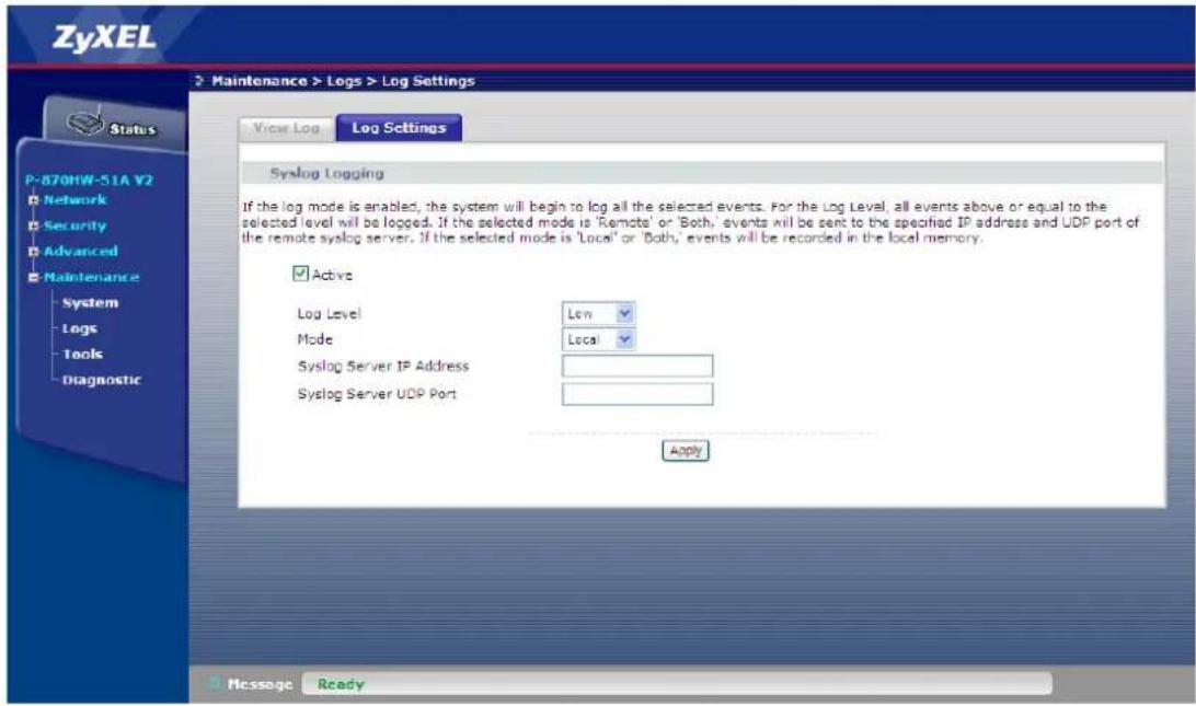
b. Show the log in the Web GUI.
- Go to Maintenance > Logs > ViewLog.
- Select the Display, e.g. "Low".
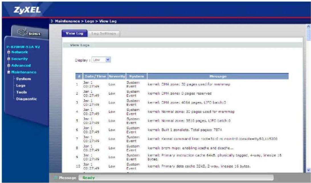
c. Show the log by Telnet.
- Login the device by Telnet,
- Type the command "syslog dump".
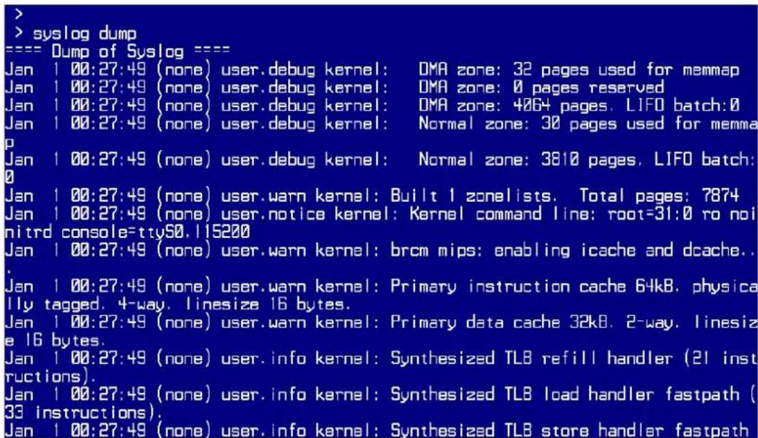
Remote Maintenance
The P-870HW-51aV2 also has the ability to send the system log outside the CPE. Let's say that we want the system log to be sent to the notebook with IP = 192.168.1.101.
a. Activate the Maintenance Log.
- Go to Maintenance > Logs > Log Settings.
- Check the Active box.
- Select the Log Level, e.g. "Low"
- Select the Mode, e.g. "Remote"
- Enter the Syslog Server IP Address, e.g. "192.168.1.101"
- Enter the Syslog Server UDP Port, e.g. "514"
- Click Apply.
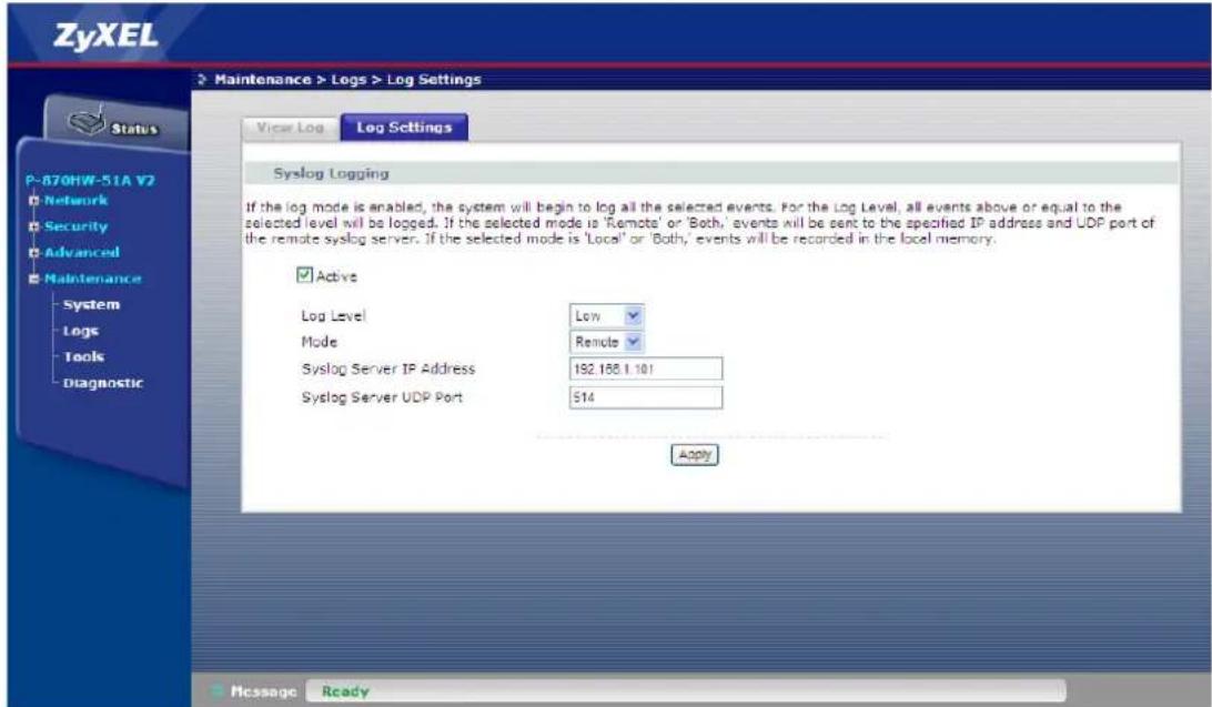
Maintenance Tool
Maintenance Procedure
a. Upload Firmware.
- Go to Maintenance > Tools > Firmware.
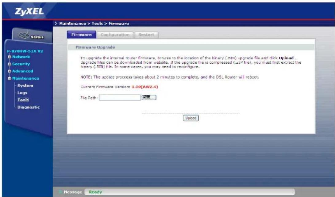
- Click Browse.
- Select the Firmware to upload and click Open.
- Click Upload.
b. Save Configuration.
- Go to Maintenance > Tools > Configuration.
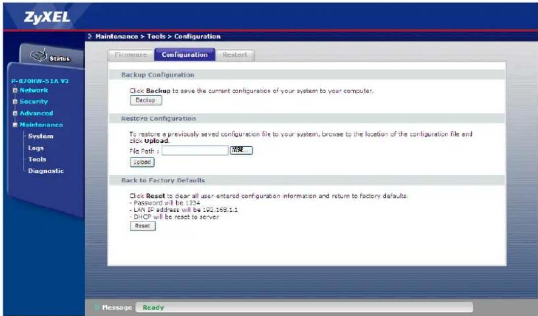
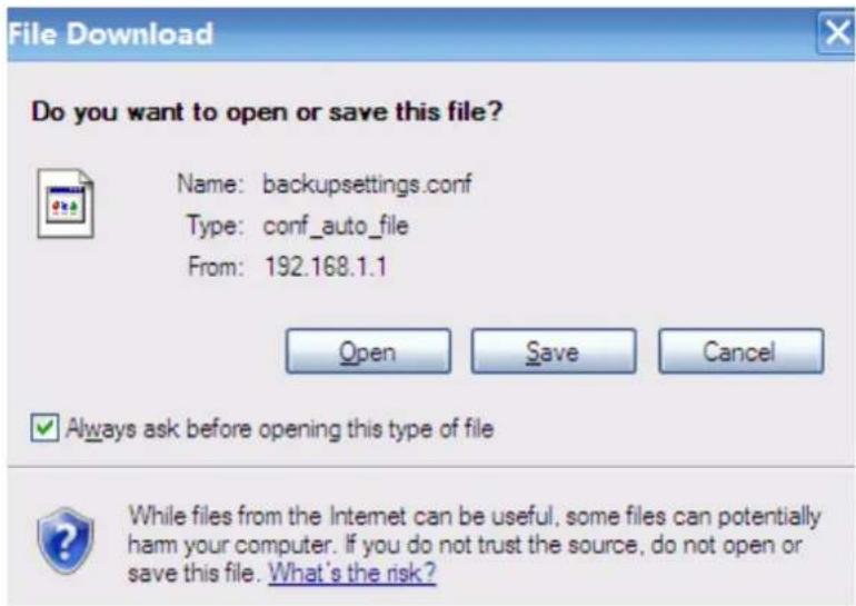
- Click Backup.
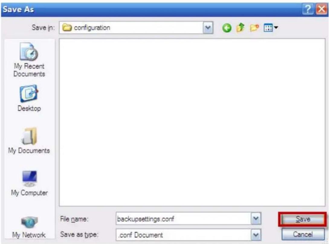
- Click Save.
- Select the directory to save and click Save.
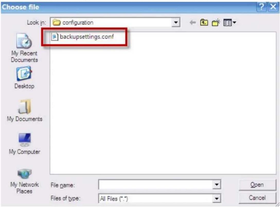
c. Upload Configuration.
- Go to Maintenance > Tools > Configuration.
- Click Browse.
- Select the configuration file to upload and click Open.
Wireless Application Notes
Wireless Introduction
WEP Configuration (Wired Equivalent Privacy) Introduction
The 802.11 standard describes the communication that occurs in the wireless LANs.
The Wired Equivalent Privacy (WEP) algorithm is used to protect wireless communication from eavesdropping, because the wireless transmissions are easier to intercept than transmissions over wired networks, and wireless is a shared medium. Everything that is transmitted or received over a wireless network can be intercepted.
The WEP relies on a secret key that is shared between a mobile station (e.g. a laptop with a wireless Ethernet card) and an access point (i.e. a base station). The secret key is used to encrypt packets before they are transmitted, and an integrity check is used to ensure that packages are not modified during the transition. The standard does not discuss how the shared key is established. In practice, most installations use a single key that is shared between all mobile stations and access points APs.
The WEP employs the key encryption algorithm, Ron's Code 4 Pseudo Random Number Generator (RC4 PRNG). The same key is used to encrypt and decrypt the data.
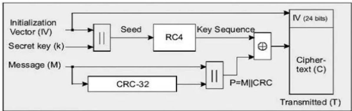
flowchart
graph TD
    A["Initialization Vector (IV)"] --> B["||"]
    C["Secret key (k)"] --> B
    B --> D["Seed"]
    D --> E["RC4"]
    E --> F["Key Sequence"]
    F --> G["⊕"]
    H["Message (M)"] --> I["CRC-32"]
    I --> J["||"]
    J --> K["P=M||CRC"]
    K --> G
    L["IV (24 bits)"] --> M["Cipher-text (C)"]
    M --> N["Transmitted (T)"]
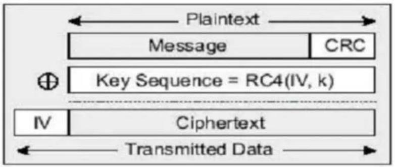
The WEP has defenses against this attack. To avoid encrypting two cipher texts with the same key stream, an Initialization Vector (IV) is used to augment the shared WEP key (secret key) and produce a different RC4 key for each packet. The IV is also included in the package. The WEP keys (secret key) are available in two types, 64-bits and 128-bits. Many times you will see them referenced as 40-bits and 104-bits instead. The reason for this misnomer is that the WEP key (40/104 bits) is concatenated with the initialization vector (24 bits) resulting in a 64/128 bit total key size.
Setting up the Access Point
natural_image
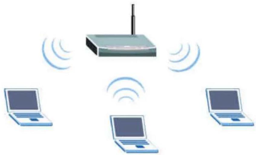
Illustration of a router connected to three laptops with wireless signal waves (no text or symbols)Most access points and clients have the ability to hold up to the 4 WEP keys simultaneously. You need to specify one of the 4 keys as default Key for data encryption. To set up the Access Point, you will need to set one of the following parameters:
- 64-bit WEP key (secret key) with 5 characters.
- 64-bit WEP key (secret key) with 10 hexadecimal digits.
- 128-bit WEP key (secret key) with 13 characters.
- 128-bit WEP key (secret key) with 26 hexadecimal digits.
IEEE 802.1x Introduction
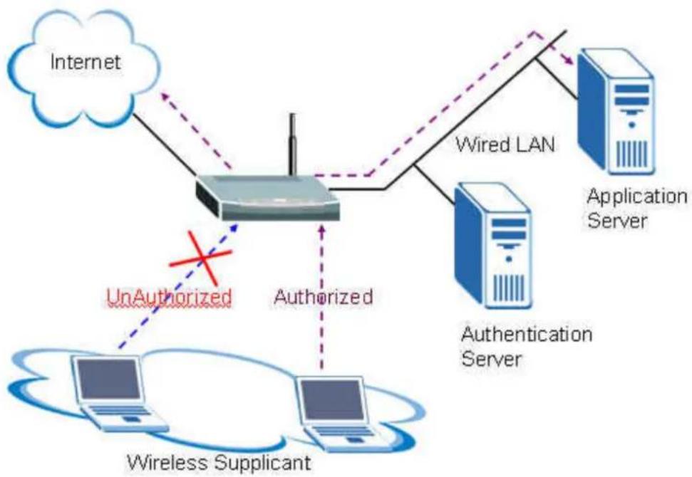
The IEEE 802.1x port-based authentication is desired to prevent the unauthorized devices (clients) from gaining access to the network. As the LANs extend to hotels, airports and corporate lobbies, the insecure environments could be created. The 802.1x port-based network access control makes use of the physical access characteristics of IEEE 802 LAN infrastructures, such as the 802.3 Ethernet, 802.11 Wireless LAN and VDSL LRE (Long Reach Ethernet), in order to provide a means of authenticating and authorizing devices attached to a LAN port that has point-to-point connection characteristics, and of preventing access to that port in case of the failure of authentication process.
flowchart
graph TD
    A["Internet"] --> B["Router"]
    B --> C["Wired LAN"]
    C --> D["Application Server"]
    B --> E["Authentication Server"]
    B --> F["UnAuthorized"]
    B --> G["Wireless Supplicant"]
    style B fill:#f9f,stroke:#333
    style C stroke-dasharray: 5 5
    style D stroke-dasharray: 5 5
    style E stroke-dasharray: 5 5
    style F stroke-dasharray: 5 5
    style G stroke-dasharray: 5 5
    subgraph Wireless Supplicant
        H["Computer"]
        I["Computer"]
        J["Computer"]
    end
    B -.->|Unauthorized| B
    style B stroke-dasharray: 5 5
    style C stroke-dasharray: 5 5
    style D stroke-dasharray: 5 5
    style E stroke-dasharray: 5 5
    style F stroke-dasharray: 5 5
    style G stroke-dasharray: 5 5
All contents copyright (c) 2009 ZyXEL Communications Corporation.
The IEEE 802.1x authentication is a client-server architecture delivered with the EAPOL (Extensible Authentication Protocol over LAN). The authentication server authenticates each client connected to an Access Point (for Wireless LAN) or switch port (for Ethernet) before accessing any services offered by the Wireless AP. The 802.1x contains tree major components:
1. Authenticator:
The device (i.e. Wireless AP) facilitates the authentication for supplicant (Wireless client) attached on the Wireless network. Authenticator controls the physical access to the network based on the authentication status of client. The authenticator acts as an intermediary (proxy) between the client and authentication server (i.e. RADIUS server), requesting the identity information from the client, verifying that information with the authentication server and relaying a response to the client.
2. Supplicant:
The station (i.e. Wireless client) is being authenticated by an authenticator attached on the Wireless network. The supplicant requests access to the LAN services and responds to the requests from the authenticator. The station must be running the 802.1x-compliant client software, such as that offered in the Microsoft Windows XP operating system, Meeting House AEGIS 802.1x client and Odyssey 802.1x client.
3. Authentication Server:
The device (i.e. RADIUS server) provides an authentication service to an authenticator. This service determines, from the credentials provided by the supplicant, whether the supplicant is authorized to access the services provided by the authenticator. The authentication server performs the actual authentication of client. It validates the identity of the supplicant. Because the authenticator acts as the proxy, the authentication service is transparent to the supplicant.
Some Wireless AP (i.e. ZyXEL Wireless AP) have built-in authentication server, therefore the external RADIUS authentication server is not needed. In this case, the Wireless AP is acted as both authenticator and authentication server.
• Authentication Port State and Authentication Control
The port state determines whether or not the supplicant (Wireless Client) is granted access to the network behind Wireless AP. There are two authentication port state on the AP, authorized state and unauthorized state.
By default, the port starts in the unauthorized state. While in this state, the port disallows all the incoming and outgoing data traffic, except for 802.1x packets. When a supplicant is successfully authenticated, the port transits to the authorized state, allowing all the traffic for client to flow normally. If a client that does not support the 802.1x is connected to an unauthorized 802.1x port, the authenticator requests the client's identity. In this situation, the client does not respond to the 802.1x request; the port remains in the unauthorized state and the client is not granted access to the network.
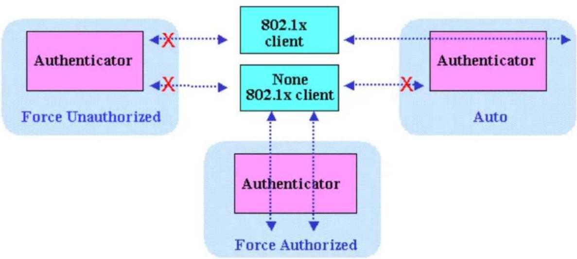
When the 802.1x is enabled, the authenticator controls the port authorization state by using the following control parameters. The following three authentication control parameters are applied in the Wireless AP.
flowchart
graph TD
    A["Authenticator"] -->|X| B["802.1x client"]
    A -->|X| C["None 802.1x client"]
    B -->|X| D["Authenticator"]
    C -->|X| D
    E["Authenticator"] --> F["Auto"]
    G["Authenticator"] --> H["Force Authorized"]
    I["Authenticator"] --> J["Force Unauthorized"]
- Force Authorized: Disables the 802.1x and causes the port to transit to the authorized state without any authentication exchange required. The port transmits
and receives the normal traffic without the 802.1x-based authentication of client. This is the default port control setting. While the AP is setup as Force Authorized, the Wireless client (supported 802.1x client or none-802.1x client) can always access the network.
-
Force Unauthorized: Causes the port to remain in the unauthorized state, ignoring all attempts by the client to authenticate. The authenticator cannot provide authentication services to the supplicants through the port. While AP is setup as Force Unauthorized, Wireless clients (supported 802.1x client or none-802.1x client) never have the access for the network.
-
Auto: Enables the 802.1x and causes the port to begin in the unauthorized state, allowing only the EAPOL frames to be sent and received through the port. The authentication process begins, when the link state of port transitions from down to up or when an EAPOL-start frame is received requests the identity of the client and begins relaying authentication messages between supplicant and the authentication server. Each supplicant attempting to access the network is uniquely identified by the authenticator by using the client's MAC address. While the AP is setup as Auto, only the Wireless client supporting the 802.1x client can access the network.
• Re-Authentication
The administrator can enable the periodic 802.1x client re-authentication and specify how often it occurs. When the re-authentication is time out, the authenticator will send the EAP-Request/Identity to reinitiate authentication process. In the ZyXEL Wireless AP 802.1x implementation, if you do not specify a time period before enabling the re-authentication, the number of seconds between re-authentication attempts is 1,800 seconds (30 minutes).
• EAPOL (Extensible Authentication Protocol over LAN)
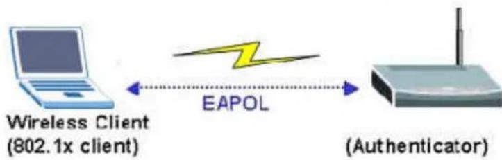
The authenticators and supplicants communicate with one another by using the Extensible Authentication Protocol (EAP and RFC-2284). The EAP was originally designed to run over PPP and to authenticate the dial-in users, but the 802.1x defines an encapsulation method for passing the EAP packets over Ethernet frames. This method is referred to as the EAP over LANs, or EAPOL. Ethernet type of EAPOL is 88-8E, two octets in length. The EAPOL encapsulations are described for IEEE 802 compliant environment, such as the 802.3 Ethernet, 802.11 Wireless LAN and Token Ring/FDDI.
flowchart
graph LR
    A["Wireless Client (802.1x client)"] -->|EAPOL| B["(Authenticator)"]
The EAP protocol can support multiple authentication mechanisms, such as MD5-challenge, One-Time Passwords, Generic Token Card, TLS and TTLS etc. Typically, the authenticator will send an initial Identity Request followed by one or more Requests for authentication information. When supplicant receives the EAP request, it will reply the associated EAP response. So far, the ZyXEL Wireless AP only supports the MD-5 challenge authentication mechanism, but will support the TLS and TTLS in the future.
EAPOL Exchange between 802.1x Authenticator and Supplicant
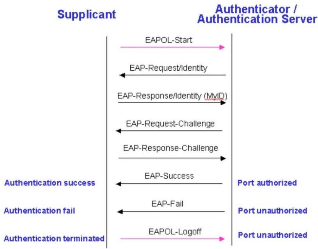
The authenticator or supplicant can initiate the authentication. If you enable the 802.1x authentication on the Wireless AP, the authenticator must initiate authentication, when it determines that the Wireless link state transits from down to up. It then sends an EAP-request/identity frame to the 802.1x client to request its identity. (Typically, the authenticator sends an initial identity/request frame followed by one or more requests for authentication information.) Upon the receipt of frame, the supplicant responds with an EAP-response/identity frame.
However, if during boot-up, the supplicant does not receive an EAP-request/identity frame from the Wireless AP, the client can initiate the authentication by sending an EAPOL-Start frame, which prompts the switch to request the supplicant's identity. In above case, authenticator is co-located with authentication server. When the supplicant supplies its identity, the authenticator directly exchanges the EAPOL to the supplicant until the authentication succeeds or fails. If the authentication succeeds, the port becomes authorized. If the authentication fails, the port becomes unauthorized. When the supplicant does not need the wireless access any more, it sends EAPOL-Logoff packet to terminate its 802.1x session and the port state will become unauthorized. The following figure displays the EAPOL exchange ping-pong chart.
flowchart
graph LR
    A["Supplicant"] --> B["EAPOL-Start"]
    B --> C["EAP-Request/Identity"]
    C --> D["EAP-Response/Identity (MyID)"]
    D --> E["EAP-Request-Challenge"]
    E --> F["EAP-Response-Challenge"]
    F --> G["EAP-Success"]
    G --> H["EAP-Fail"]
    H --> I["EAPOL-Logoff"]
    I --> J["Authentication failed"]
    J --> K["Authentication success"]
    K --> L["Authentication terminated"]
    L --> M["Port unauthorized"]
    M --> N["Port unauthorized"]
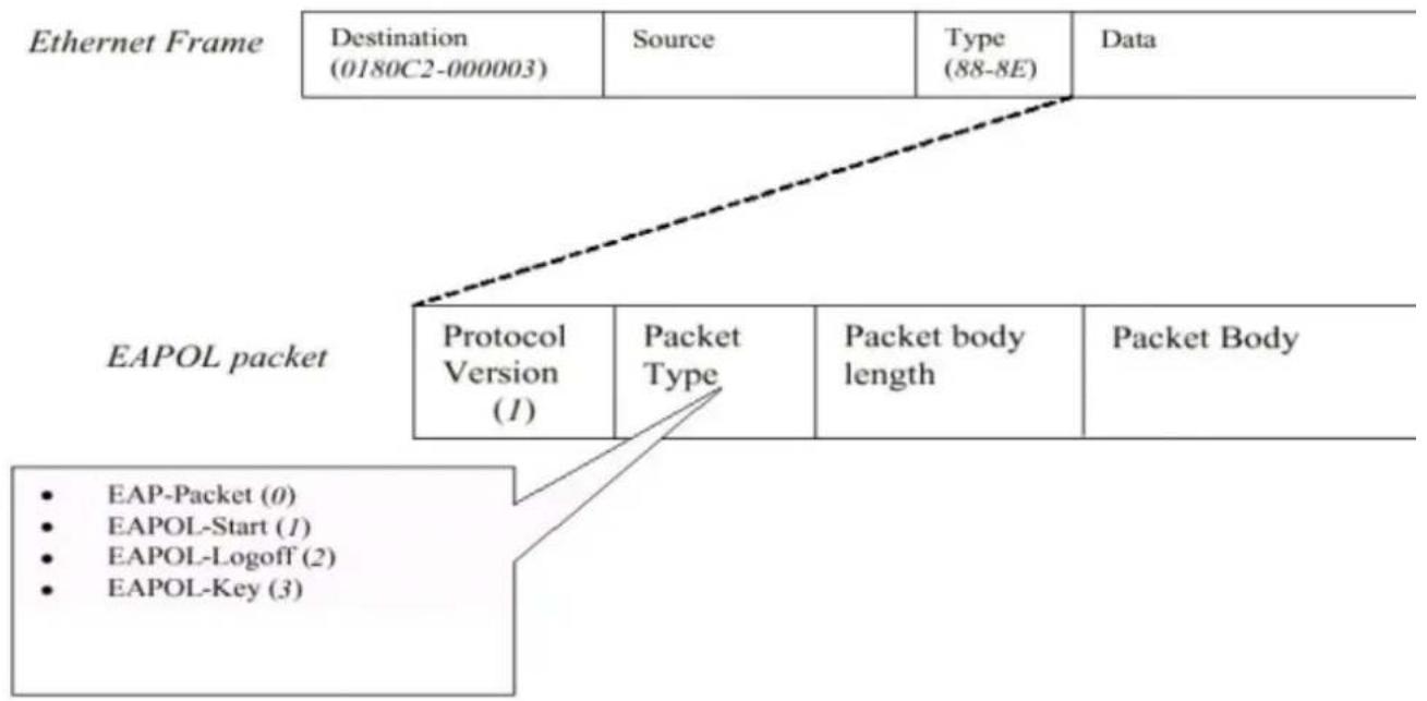
The EAPOL packet contains the following fields: protocol version, packet type, packet body length, and packet body. Most of the fields are obvious. The packet type can have four different values and these values are described as followed:
flowchart
graph TD
    A["Destination (0180C2-000003)"] --> B["Source"]
    B --> C["Type (88-8E)"]
    C --> D["Data"]
    E["EAPOL packet"] --> F["Protocol Version (1)"]
    F --> G["Packet Type"]
    G --> H["Packet body length"]
    H --> I["Packet Body"]
    J["EAPOL-Start (1)"]
    K["EAPOL-Logoff (2)"]
    L["EAPOL-Key (3)"]
    M["EAP-Packet (0)"]
- EAP-Packet: Both the supplicant and authenticator send this packet, when the authentication is taking place. This is the packet that contains either the MD5-Challenge or TLS information required for authentication.
- EAPOL-Start: This supplicant sends this packet, when it wants to initiate the authentication process.
- EAPOL-Logoff: The supplicant sends this packet, when it wants to terminate its 802.1x session.
- EAPOL-Key: This is used for the TLS authentication method. The Wireless AP uses this packet to send the calculated WEP key to the supplicant after the TLS negotiation has completed between the supplicant and RADIUS server.
Wi-Fi Protected Access Introduction
The Wi-Fi Protected Access (WPA) is a subset of the IEEE 802.11i security specification draft. Key differences between the WAP and WEP are user authentication and improved data encryption. The WAP applies the IEEE 802.1x Extensible Authentication Protocol (EAP) to authenticate wireless clients using an external RADIUS database. You can not use the P-660HW-Tx v2's local user database for WPA authentication purpose, since the local user database uses the MD5 EAP which can not generate keys.
The WPA improves data encryption by using Temporal Key Integrity Protocol (TKIP), Message Integrity Check and IEEE 802.1x. Temporal Key Integrity Protocol uses 128-bits keys that are dynamically generated and distributed by the authentication server. It includes a per-packet key mixing function, a Message Integrity Check (MIC) named Michael, an extend initialization vector (IV) with sequencing rules and a re-keying mechanism.
If you do not have an external RADIUS and server, you should use the WPA-PSK (WPA Pre-Share Key) that only requires a single (identical) password entered into each access point, wireless gateway and wireless client. As long as the passwords match, a client will be granted to access to a WLAN.
Wireless Configuration (P-870H-51aV2 does not support wireless features)
Activate the WLAN interface of the P-870HW-51aV2 and connect the notebook (802.11bg wireless NIC required) under the WPA-PSK as its security mode.
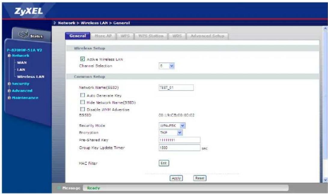
a. Wireless Setup.
- Go to Network > Wireless LAN > General.
- Check the Active Wireless LAN box.
- Enter the Network Name(SSID), e.g. "TEST_01".
- Select the Security Mode, e.g. "WPA-PSK".
- Select the WPA Encryption, e.g. "TKIP".
- Enter the Pre-Shared Key, e.g. "11111111".
- Enter the WPA Group Key Update Timer, e.g. "1800".
- Click Apply.
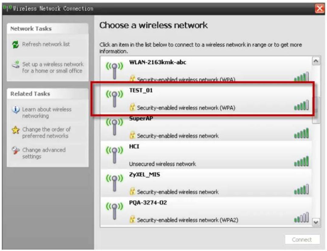
Show all the wireless networks in your notebook (802.11bg wireless NIC required):
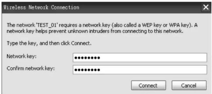
Enter the WPA-PSK pre-shared key.
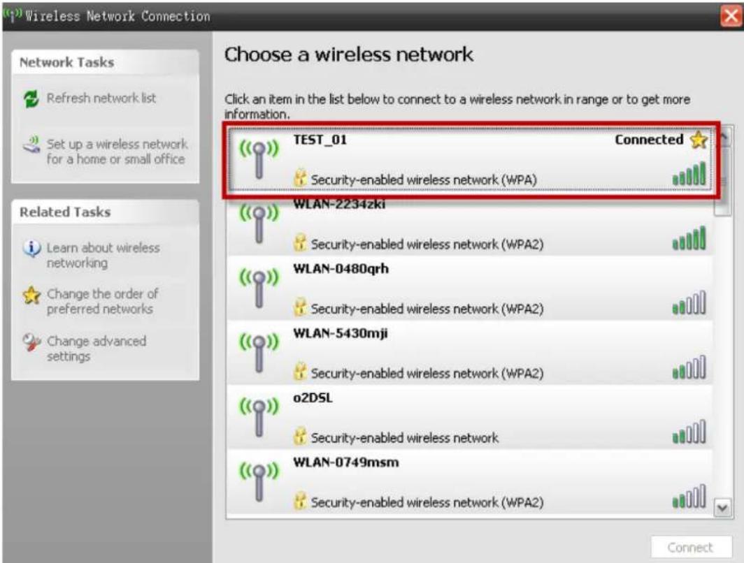
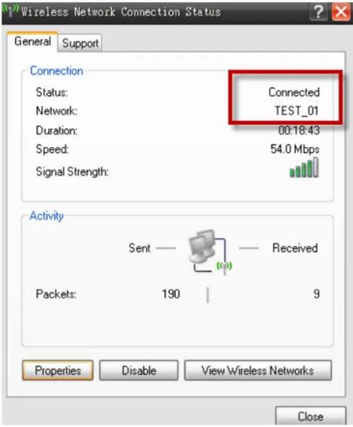
We can see that the notebook is now connected to the WLAN interface of the P-870HW-51aV2.
b. Wireless Setup Hiding the SSID.
- Go to Network > Wireless LAN > General.
- Check the Active Wireless LAN box.
- Enter the Network Name(SSID), e.g. "TEST_01".
- Check the Hide Network Name(SSID) box
- Select the Security Mode, e.g. "WPA-PSK".
- Select the WPA Encryption, e.g. "TKIP".
- Enter the Pre-Shared Key, e.g. "11111111".
- Enter the WPA Group Key Update Timer, e.g. "1800".
- Click Apply.
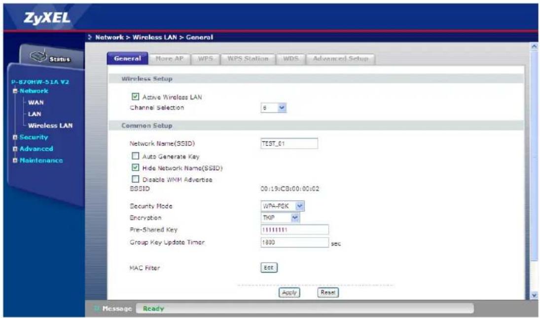
Show all the wireless networks in your notebook:
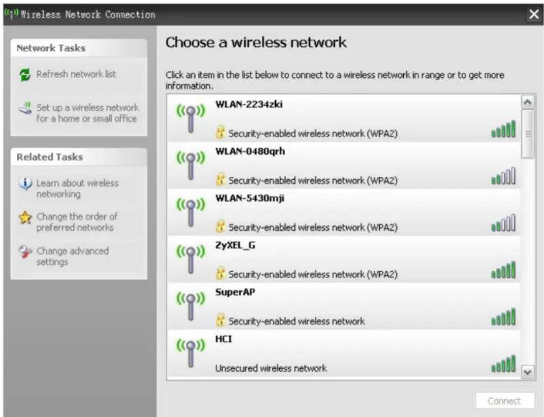
As we can see, we cannot find the SSID "TEST_01".
To connect to "TEST_01", we need to configure the "Wireless Network Connection Properties" of the notebook WLAN interface:
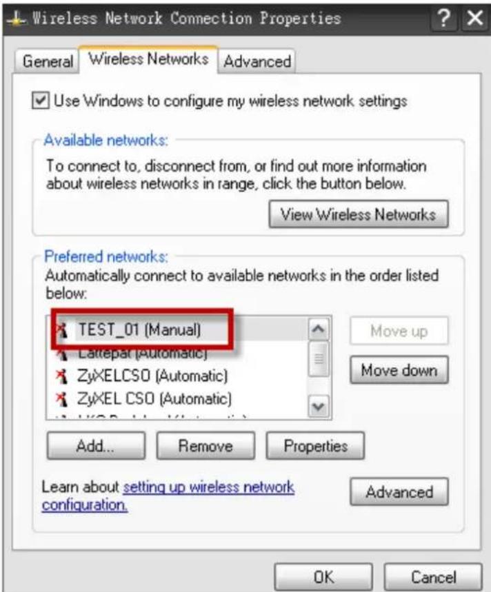
Go "Connection" tab and check the box under the name of "Connect when this network is in range".
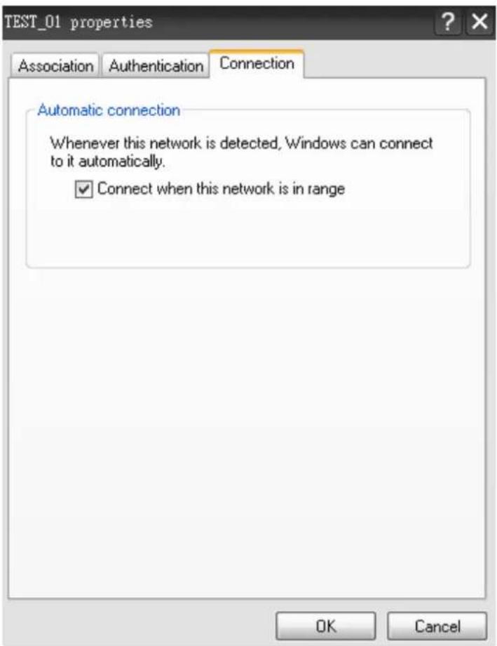
Then we will see the notebook connected to the "TEST_01", even though the SSID is now displayed in the broadcast list.
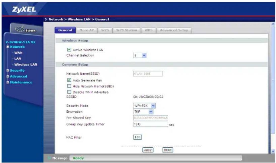
c. Wireless Setup Using "Auto Generate Key".
- Go to Network > Wireless LAN > General.
- Check the Active Wireless LAN box.
- Check the Auto Generate Key box
- Select the Security Mode, e.g. "WPA-PSK".
- Select the WPA Encryption, e.g. "TKIP".
- Enter the WPA Group Key Update Timer, e.g. "1800".
- Click Apply.
Show all the wireless networks in your notebook:
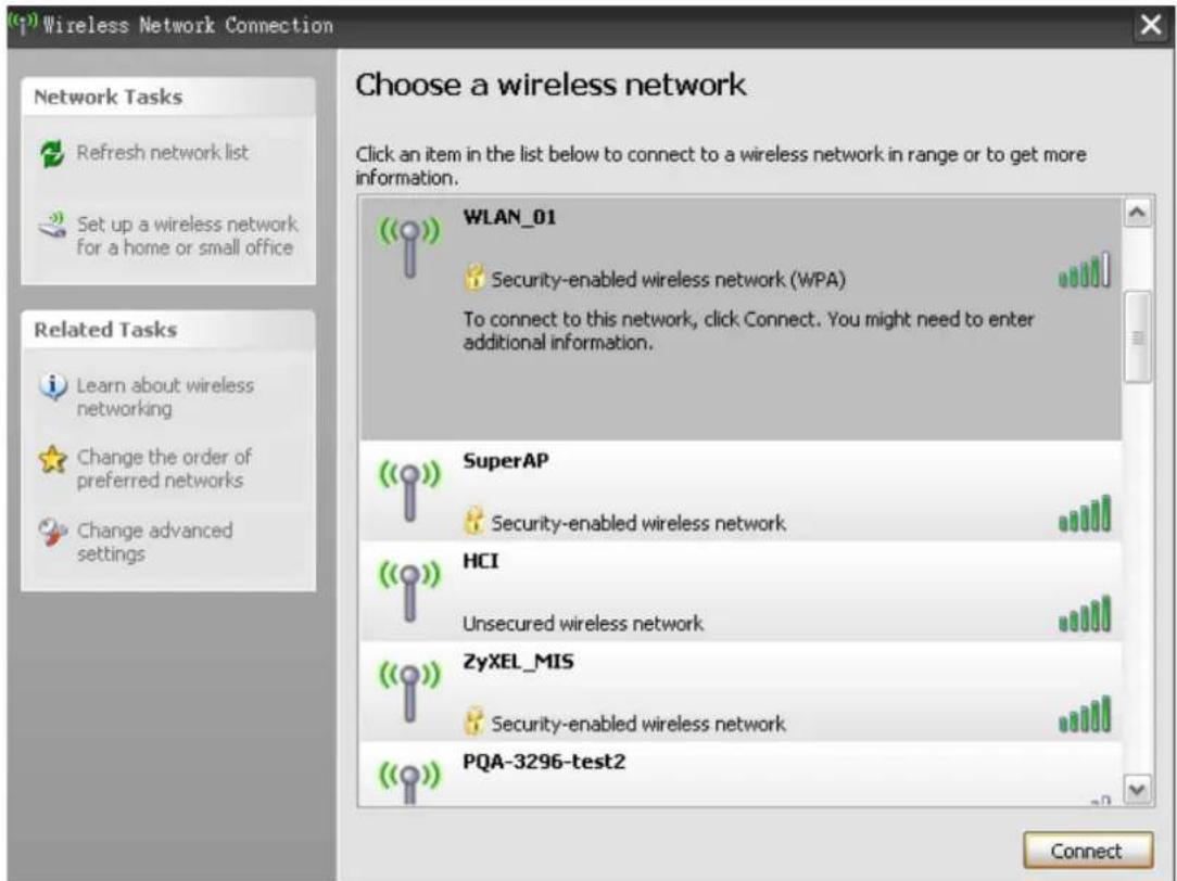
Enter the WPA-PSK pre-shared key auto-generated by P-870HW-51aV2.
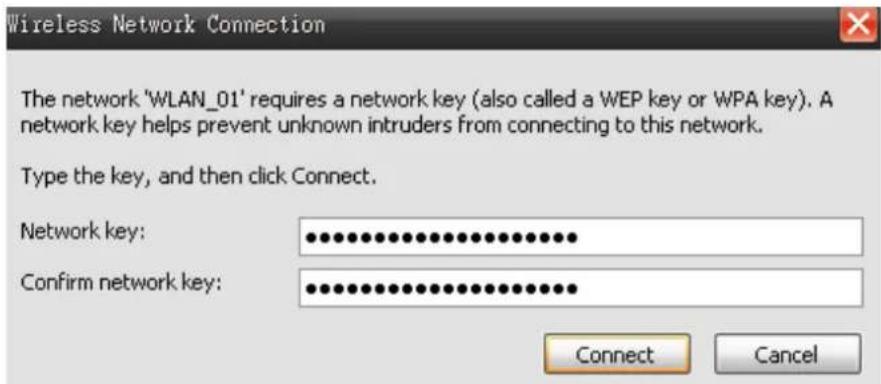
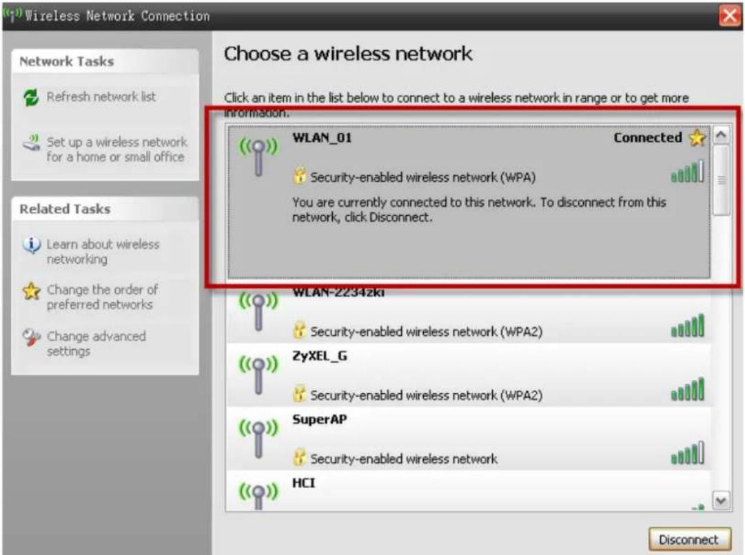
We can see that the notebook is now connected to the WLAN interface of the P-870HW-51aV2.
WPS Application Notes
What is WPS?
Wi-Fi Protected Setup (WPS) is a standard created by the Wi-Fi Alliance for easy and secure establishment of a wireless home/office network. The goal of the WPS protocol is to simplify the process for configuring the security of the wireless network, and thus calling the name Wi-Fi Protected Setup.
There are several different methods defined in WPS to simplify the process of configuration. P-870HW-51aV2 supports two of those methods, which are the PIN Method and the PBC Method.
PIN Method:
A PIN (Personal Identification Number) has to be read from either a sticker on the new wireless client device or a display, and entered at either the wireless access point (AP) or a Registrar of the network.
PBC Method:
A simple action of “push button” suffices the process to activate the security of the wireless network and at the same time be subscribed in it.
WPS configuration
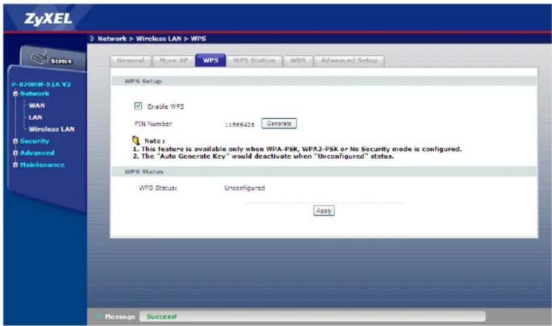
a. WPS Setup
- Go to Network > Wireless LAN > WPS.
- Check the Enable WPS box.
- Click Apply.
b. WPS Station Setup
- Go to Network > Wireless LAN > WPS Station.
- Click the Push-Button
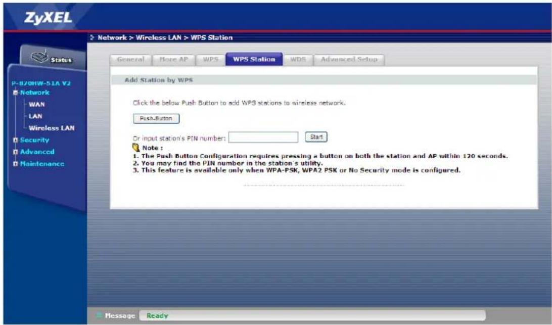
Note: You must press the other wireless device's WPS button within 2 minutes of pressing this button.
Product FAQ
Will the device work with my Internet connection?
P-870HW-51aV2 is designed to be compatible with major ISPs utilize VDSL as a broadband service. P-870HW-51aV2 offers Ethernet ports to connect to your computer so the device is placed in the line between the computer and your ISP. If your ISP supports PPPoE you can also use the device, because PPPoE is supported in the device.
Why do I need to use P-870HW-51aV2?
You need an VDSL modem/router to use with VDSL line, P-870HW-51aV2 is an ideal device for such application. The device has 4 Ethernet ports (LAN ports) and one VDSL WAN port. You should connect the computer to the LAN port and connect the VDSL line to the WAN port. If the ISP uses PPPoE you need the user account to access Internet.
What is PPPoE?
PPPoE stands for Point-to-Point Protocol over Ethernet that is an IETF draft standard specifying how a computer interacts with a broadband modem (i.e. xDSL, cable, wireless, etc.) to achieve access to the high-speed data networks via a familiar PPP dialer such as 'Dial-Up Networking' user interface. PPPoE supports a broad range of existing applications and service including authentication, accounting, secure access and configuration management. There are some service providers running of PPPoE today. Before configuring PPPoE in the device, please make sure your ISP supports PPPoE.
Does the device support PPPoE?
Yes. The device supports PPPoE.
How do I know I am using PPPoE?
PPPoE requires a user account to login to the provider's server. If you need to configure a user name and password on your computer to connect to the ISP you are probably using PPPoE. If you are simply connected to the Internet when you turn on your computer, you probably are not. You can also check your ISP or the information sheet given by the ISP. Please choose PPPoE as the encapsulation type in the device if the ISP uses PPPoE.
Why does my provider use PPPoE?
PPPoE emulates a familiar Dial-Up connection. It allows your ISP to provide services using their existing network configuration over the broadband connections. Besides, PPPoE supports a broad range of existing applications and service including authentication, accounting, secure access and configuration management.
Which Internet Applications can I use with the device?
Most common applications include MIRC, PPTP, ICQ, Cu-SeeMe, NetMeeting, IP/TV, RealPlayer, VDOLive, Quake, QuakeII, QuakeIII, StarCraft, & Quick Time.
How can I configure the device?
a. Telnet remote management- driven user interface for easy remote management
b. Web browser- web server embedded for easy configurations
What network interface does the device support?
The device supports 10/100M Ethernet to connect to the LAN computer or hub/switch and an up to 100M VDSL interface to the ISP.
What can we do with the device?
Browse the World Wide Web (WWW), send and receive individual e-mail, and download software. These are just a few of many benefits you can enjoy when you put the whole office on-line with the device.
Does device support dynamic IP addressing?
The device supports either a static or dynamic IP address from ISP.
What is the difference between the internal IP and the real IP from my ISP?
Internal IPs is sometimes referred to as virtual IPs. They are a group of up to 255 IPs that are used and recognized internally on the local area network. They are not intended to be recognized on the Internet. The real IP from ISP, instead, can be recognized or pinged by another real IP. The Device works like an intelligent router that route between the virtual IP and the real IP.
How does e-mail work through the device?
It depends on what kind of IP you have: Static or Dynamic. If your company has a domain name, it means that you have a static IP address. Suppose your company's e-mail address is xxx@mycompany.com. Joe and Debbie will be able to send e-mail through the device using jane@mycompany.com and debbie@mycompany.com respectively as their e-mail addresses. They will be able to retrieve their individual private and secure e-mail, if they have been assigned the proper access right.
If your company does not have a domain name, it means that your ISP provides you with a dynamic IP address.
Suppose your company's e-mail address is mycompany@ispname.com. Jane and John will be able to send e-mail through the device using "jane"mycompany@ispname.com and "john"mycompany@ispname.com respectively as their e-mail addresses. Again, they will be able to retrieve their individual private and secured e-mail, if they have been assigned the proper access right.
Is it possible to access a server running behind SUA from the outside Internet? If possible, how?
Yes, it is possible because the device delivers the packet to the local server by looking up to a SUA server table. Therefore, to make a local server accessible to the outside users, the port number and the inside IP address of the server must be configured.
What DHCP capability does the device support?
The device supports DHCP client (Ethernet encap) on the WAN port and DHCP server on the LAN port. The device's DHCP client allows it to get the Internet IP address from ISP automatically if your ISP use DHCP as a method to assign IP address. The device's internal DHCP server allows it to automatically assign IP and DNS addresses to the clients on the local LAN.
How do I used the reset button, more over what field of parameter will be reset by reset button?
You can used a sharp pointed object insert it into the little reset hole beside the power connector. Press down the reset button and hold down for approx 5 second, the unit will be reset. When the reset button is pressed the devices all parameter will be reset back to factory default include, password, and IP address.
The default IP address is 192.168.1.1, Password 1234.
What network interface does the new device series support?
The new device series support auto MDX/MDIX 10/100M Ethernet LAN port to connect to the computer or Switch on LAN.
How does the device support TFTP?
In addition to the direct console port connection, the device supports the uploading/download of the firmware and configuration file using TFTP (Trivial File Transfer Protocol) over LAN.
Can the device support TFTP over WAN?
Although TFTP should work over WAN as well, it is not recommended because of the potential data corruption problems.
How fast can the data go?
The speed of the VDSL is only one part of the equation. There are a combination of factors starting with how fast your PC can handle IP traffic, then how fast your PC to cable modem interface is, then how fast the cable modem system runs and how much congestion there is on the cable network, then how big a pipe there is at the head end to the rest of the Internet.
Different models of PCs and Macs are able to handle IP traffic at varying speeds. Very few can handle it at 100 Mbps.
To create the appearance of faster network access, service companies plan to store or "cache" frequently requested web sites and Usenet newsgroups on a server at their head-end. Storing data locally will remove some of the bottleneck at the backbone connection.
How fast can they go? In a perfect world (or lab) they can receive data at speeds up to 100 Mbps. In the real world, with cost conscious cable companies running the systems, the speed will probably fall behind the speed that the ISP appointed at the first place.
What is Multi-NAT?
NAT (Network Address Translation-NAT RFC 1631) is the translation of an Internet Protocol address used within one network to a different IP address known within another network. One network is designated the inside network and the other is the outside. Typically, a company maps its local inside network addresses to one or more global outside IP addresses and "unmaps" the global IP addresses on incoming packets back into local IP addresses. The IP addresses for the NAT can be either fixed or dynamically assigned by the ISP. In addition, you can designate servers, e.g., a web server and a telnet server, on your local network and make them accessible to the outside world. If you do not define any servers, NAT offers the additional benefit of firewall protection. In such case, all incoming connections to your network will be filtered out by the device, thus preventing intruders from probing your network.
The SUA feature that the device supports previously operates by mapping the private IP addresses to a global IP address. It is only one subset of the NAT. The device supports most of the features of the NAT based on RFC 1631, and we call this feature as 'Multi-NAT'. For more information on IP address translation, please refer to RFC 1631, The IP Network Address Translator (NAT).
When do I need Multi-NAT?
a. Make local server accessible from outside Internet
When NAT is enabled the local computers are not accessible from outside. You can use Multi-NAT to make an internal server accessible from outside.
a. Support Non-NAT Friendly Applications
Some servers providing Internet applications such as some mIRC servers do not allow users to login using the same IP address. Thus, users on the same network can not login to the same server simultaneously. In this case it is better to use Many-to-Many No Overload or One-to-One NAT mapping types, thus each user login to the server using a unique global IP address.
What IP/Port mapping does Multi-NAT support?
NAT supports five types of IP/port mapping. They are: One to One, Many to One, Many to Many Overload, Many to Many No Overload and Server. The details of the mapping between ILA and IGA are described as below. Here we define the local IP addresses as the Internal Local Addresses (ILA) and the global IP addresses as the Inside Global Address (IGA),
1. One to One
In One-to-One mode, the device maps one ILA to one IGA.
2. Many to One
In Many-to-One mode, the device maps multiple ILA to one IGA. This is equivalent to SUA (i.e., PAT, port address translation), ZyXEL's Single User Account feature that previous ZyNOS routers supported (the SUA only option in today's routers).
3. Many to Many Overload
In Many-to-Many Overload mode, the device maps the multiple ILA to shared IGA.
4. Many to Many No Overload
In Many-to-Many No Overload mode, the device maps each ILA to unique IGA.
5. Server
In Server mode, the device maps multiple inside servers to one global IP address. This allows us to specify multiple servers of different types behind the NAT for outside access. Note: if you want to map each server to one unique IGA please use the One-to-One mode.
The following table summarizes these types.
| NAT Type | IP Mapping |
| One-to-One | ILA1<---->IGA1 |
| Many-to-One (SUA/PAT) | ILA1<---->IGA1ILA2<---->IGA1... |
| Many-to-Many Overload | ILA1<---->IGA1ILA2<---->IGA2ILA3<---->IGA1ILA4<---->IGA2... |
| Many-to-Many No Overload | ILA1<---->IGA1ILA2<---->IGA2ILA3<---->IGA3ILA4<---->IGA4... |
| Server | Server 1 IP<---->IGA1Server 2 IP<---->IGA1 |
What is the difference between SUA and Multi-NAT?
SUA (Single User Account) in previous ZyNOS versions is a NAT set with 2 rules, Many-to-One and Server. The device now has Full Feature NAT support to map global IP addresses to local IP addresses of clients or servers. With multiple global IP addresses, multiple severs of the same type (e.g., FTP servers) are allowed on the LAN for outside access. In previous ZyNOS versions that supported SUA 'visible' servers had to be of different types. The device supports NAT sets on a remote node basis. They are reusable, but only one set is allowed for each remote node. The device supports 2 sets since there is only one remote node. The default SUA (Read Only) is a convenient, pre-configured, read only, Many-to-One mapping set, sufficient for most purposes and helpful to people already familiar with SUA in previous ZyNOS versions.
What is BOOTP/DHCP?
BOOTP stands for Bootstrap Protocol. DHCP stands for Dynamic Host Configuration Protocol. Both are mechanisms to dynamically assign an IP address for a TCP/IP client by the server. In this case, the device is a BOOTP/DHCP server. Win95 and WinNT clients use DHCP to request an internal IP address, while WFW and WinSock clients use BOOTP. TCP/IP clients may specify their own IP or utilize BOOTP/DHCP to request an IP address.
What is DDNS?
The Dynamic DNS service allows you to alias a dynamic IP address to a static hostname, allowing your computer to be more easily accessed from various locations on the Internet. To use the service, you must first apply an account from several free Web servers such as WWW.DYNDNS.ORG.
Without DDNS, we always tell the users to use the WAN IP of the 312 to reach our internal server. It is inconvenient for the users if this IP is dynamic. With DDNS supported by the device, you apply a DNS name (e.g., www.zyxel.com.tw) for your server (e.g., Web server) from a DDNS server. The outside users can always access the web server using the www.zyxel.com.tw regardless of the WAN IP of the 312.
When the ISP assigns the device a new IP, the device updates this IP to DDNS server so that the server can update its IP-to-DNS entry. Once the IP-to-DNS table in the DDNS server is updated, the DNS name for your web server (i.e., www.zyxel.com.tw) is still usable.
When do I need DDNS service?
When you want your internal server to be accessed by using DNS name rather than using the dynamic IP address we can use the DDNS service. The DDNS server allows to alias a dynamic IP address to a static hostname. Whenever the ISP assigns you a new IP, the device sends this IP to the DDNS server for its updates.
Wireless FAQ
What is a Wireless LAN?
Wireless LANs provide all the functionality of wired LANs, without the need for physical connections (wires). Data is modulated onto a radio frequency carrier and transmitted through the ether. Typical bit-rates are 11Mbps and 54Mbps, although in practice data throughput is half of this. Wireless LANs can be formed simply by equipping PC's with wireless NICs. If connectivity to a wired LAN is required an Access Point (AP) is used as a bridging device. AP's are typically located close to the centre of the wireless client population.
What are the advantages of Wireless LANs?
a. Mobility:
Wireless LAN systems can provide LAN users with access to real-time information anywhere in their organization. This mobility supports productivity and service opportunities not possible with wired networks.
b. Installation Speed and Simplicity:
Installing a wireless LAN system can be fast and easy and can eliminate the need to pull cable through walls and ceilings.
c. Installation Flexibility:
Wireless technology allows the network to go where wire cannot go.
d. Reduced Cost-of-Ownership:
While the initial investment required for wireless LAN hardware can be higher than the cost of wired LAN hardware, overall installation expenses and life-cycle costs can be significantly lower. Long-term cost benefits are greatest in dynamic environments requiring frequent moves and changes.
e. Scalability:
Wireless LAN systems can be configured in a variety of topologies to meet the needs of specific applications and installations. Configurations are easily changed and range from peer-to-peer networks suitable for a small number of users to full infrastructure
networks of thousands of users that enable roaming over a broad area.
What are the disadvantages of Wireless LANs?
The speed of Wireless LAN is still relative slower than wired LAN. The most popular wired LAN is operated in 100Mbps, which is almost 10 times of that of Wireless LAN (10Mbps). A faster wired LAN standard (1000Mbps), which is 100 times faster, becomes popular as well. The setup cost of Wireless LAN is relative high because the equipment cost including access point and PCMCIA Wireless LAN card is higher than hubs and CAT 5 cables.
Where can you find wireless 802.11 networks?
Airports, hotels, and even coffee shops like Starbucks are deploying 802.11 networks so people can wirelessly browse the Internet with their laptops. As these types of networks increase, this will create additional security risk for the remote user if not properly protected.
What is an Access Point?
The AP (access point also known as a base station) is the wireless server that with an antenna and a wired Ethernet connection that broadcasts information using radio signals. AP typically act as a bridge for the clients. It can pass information to wireless LAN cards that have been installed in computers or laptops allowing those computers to connect to the campus network and the Internet without wires.
What is IEEE 802.11?
The IEEE 802.11 is a wireless LAN industry standard, and the objective of IEEE 802.11 is to make sure that different manufactures' wireless LAN devices can communicate to each other.802.11 provides 1 or 2 Mbps transmission in the 2.4 GHz ISM band using either FHSS or DSSS.
What is 802.11b?
802.11b is the first revision of 802.11 standard allowing data rates up to 11Mbps in the 2.4GHz ISM band. Also known as 802.11 High-Rate and Wi-Fi. 802.11b only uses DSSS, the maximum speed of 11Mbps has fallbacks to 5.5, 2 and 1Mbps.
How fast is 802.11b?
The IEEE 802.11b standard has a nominal speed of 11 megabits per second (Mbps). However, depending on signal quality and how many other people are using the wireless ethernet through a particular Access Point, usable speed will be much less (on the order of 4 or 5 Mbps, which is still substantially faster than most dialup, cable and DSL modems).
What is 802.11a?
802.11a the second revision of 802.11 that operates in the unlicensed 5 GHz band and allows transmission rates of up to 54Mbps. 802.11a uses OFDM (orthogonal frequency division multiplexing) as opposed to FHSS or DSSS. Higher data rates are possible by combining channels. Due to higher frequency, range is less than lower frequency systems (i.e., 802.11b and 802.11g) and can increase the cost of the overall solution because a greater number of access points may be required. 802.11a is not directly compatible with 802.11b or 802.11g networks. In other words, a user equipped with an 802.11b or 802.11g radio card will not be able to interface directly to an 802.11a access point. Multi-mode NICs will solve this problem.
What is 802.11g?
802.11g is an extension to 802.11b. 802.11g increases 802.11b's data rates to 54 Mbps and still utilise the the 2.4 GHz ISM. Modulation is based upon OFDM (orthogonal frequency division multiplexing) technology. An 802.11b radio card will interface directly with an 802.11g access point (and vice versa) at 11 Mbps or lower depending on range. The range at 54 Mbps is less than for 802.11b operating at 11 Mbps.
Is it possible to use products from a variety of vendors?
Yes. As long as the products comply to the same IEEE 802.11 standard. The Wi-Fi logo is used to define 802.11b compatible products. Wi-Fi5 is a compatibility standard for 802.11a products running in the 5GHz band.
What is Wi-Fi?
The Wi-Fi logo signifies that a product is interoperable with wireless networking equipment from other vendors. A Wi-Fi logo product has been tested and certified by the Wireless Ethernet Compatibility Alliance (WECA). The Socket Wireless LAN Card is Wi-Fi certified, and that means that it will work (interoperate) with any brand of Access Point that is also Wi-Fi certified.
What types of devices use the 2.4GHz Band?
Various spread spectrum radio communication applications use the 2.4 GHz band. This includes WLAN systems (not necessarily of the type IEEE 802.11b), cordless phones, wireless medical telemetry equipment and Bluetooth ^™ short-range wireless applications, which include connecting printers to computers and connecting modems or hands-free kits to mobile phones.
Does the 802.11 interfere with Bluetooth devices?
Any time devices are operated in the same frequency band, there is the potential for interference.
Both the 802.11b and Bluetooth devices occupy the same2.4-to-2.483-GHz unlicensed frequency range-the same band. But a Bluetooth device would not interfere with other 802.11 devices much more than another 802.11 device would interfere. While more collisions are possible with the introduction of a Bluetooth device, they are also possible with the introduction of another 802.11 device, or a new 2.4 GHz cordless phone for that matter. But, BlueTooth devices are usually low-power, so the effects that a Bluetooth device may have on an 802.11 network, if any, aren't far-reaching.
Can radio signals pass through walls?
Transmitting through a wall is possible depending upon the material used in its construction. In general, metals and substances with a high water content do not allow radio waves to pass through. Metals reflect radio waves and concrete attenuates radio waves. The amount of attenuation suffered in passing through concrete will be a function of its thickness and amount of metal re-enforcement used.
What are potential factors that may cause interference among WLAN products?
Factors of interference:
-
Obstacles: walls, ceilings, furniture... etc.
-
Building Materials: metal door, aluminum studs.
-
Electrical devices: microwaves, monitors, electric motors.
Solution :
-
Minimizing the number of walls and ceilings
-
Antenna is positioned for best reception
-
Keep WLAN products away from electrical devices, eg: microwaves, monitors, electric motors,..., etc.
-
Add additional APs if necessary.
What's the difference between a WLAN and a WWAN?
WLANs are generally privately owned, wireless systems that are deployed in a corporation, warehouse, hospital, or educational campus setting. Data rates are high and there are no per-packet charges for data transmission.
WWANs are generally publicly shared data networks designed to provide coverage in metropolitan areas and along traffic corridors. WWANs are owned by a service provider or carrier. Data rates are low and charges are based on usage. Specialized applications are characteristically designed around short, burst messaging.
What is Ad Hoc mode?
A wireless network consists of a number of stations without access points. Without using an access point or any connection to a wired network.
What is Infrastructure mode?
Infrastructure mode implies connectivity to a wired communications infrastructure. If such connectivity is required the Access Points must be used to connect to the wired LAN backbone. Wireless clients have their configurations set for "infrastructure mode" in order to utilize access points relaying.
How many Access Points are required in a given area?
This depends on the surrounding terrain, the diameter of the client population, and the number of clients. If an area is large with dispersed pockets of populations then extension points can be used for extend coverage.
What is Direct-Sequence Spread Spectrum Technology – (DSSS)?
DSSS spreads its signal continuously over a wide frequency band. DSSS maps the information bearing bit-pattern at the sending station into a higher data rate bit sequence using a "chipping" code. The chipping code (also known as processing gain) introduces redundancy which allows data recovery if certain bit errors occur during transmission. The FCC rules the minimum processing gain should be 10, typical systems use processing gains of 20. IEEE 802.11b specifies the use of DSSS.
What is Frequency-hopping Spread Spectrum Technology – (FHSS)?
FHSS uses a narrowband carrier which hops through a predefined sequence of several frequencies at a specific rate. This avoids problems with fixed channel narrowband noise and simple jamming. Both transmitter and receiver must have their hopping sequences synchronized to create the effect of a single "logical channel". To an unsynchronized receivers an FHSS transmission appears to be short-duration impulse noise. 802.11 may use FHSS or DSSS.
Do I need the same kind of antenna on both sides of a link?
No. Provided the antenna is optimally designed for 2.4GHz or 5GHz operation. WLAN NICs often include an internal antenna which may provide sufficient reception.
Why the 2.4 Ghz Frequency range?
This frequency range has been set aside by the FCC, and is generally labeled the ISM band. A few years ago Apple and several other large corporations requested that the FCC allow the development of wireless networks within this frequency range. What we have today is a protocol and system that allows for unlicensed use of radios within a prescribed power level. The ISM band is populated by Industrial, Scientific and Medical devices that are all low power devices, but can interfere with each other.
What is Server Set ID (SSID)?
SSID is a configurable identification that allows clients to communicate to the appropriate base station. With proper configuration, only clients that are configured with the same SSID can communicate with base stations having the same SSID. SSID from a security point of view acts as a simple single shared password between base stations and clients.
What is an ESSID?
ESSID stands for Extended Service Set Identifier and identifies the wireless LAN. The ESSID of the mobile device must match the ESSID of the AP to communicate with the AP. The ESSID is a 32-character maximum string and is case-sensitive.
How do I secure the data across an Access Point's radio link?
Enable Wired Equivalency Protocol (WEP) or Wi-Fi Protected Access (WPA) to encrypt the payload of packets sent across a radio link.
What is WEP?
Wired Equivalent Privacy. WEP is a security mechanism defined within the 802.11 standard and designed to make the security of the wireless medium equal to that of a cable (wire). WEP data encryption was designed to prevent access to the network by "intruders" and to prevent the capture of wireless LAN traffic through eavesdropping. WEP allows the administrator to define a set of respective "Keys" for each wireless network user based on a "Key String" passed through the WEP encryption algorithm. Access is denied by anyone who does not have an assigned key. WEP comes in 40/64-bit and 128-bit encryption key lengths. Note, WEP has shown to have fundamental flaws in its key generation processing.
What is the difference between 40-bit and 64-bit WEP?
40 bit WEP & 64 bit WEP are the same encryption level and can interoperate. The lower level of WEP encryption uses a 40 bit (10 Hex character) as "secret key" (set by user), and a 24 bit "Initialization Vector" (not under user control) (40+24=64). Some vendors refer to this level of WEP as 40 bit, others as 64 bit.
What is a WEP key?
A WEP key is a user defined string of characters used to encrypt and decrypt data.
A WEP key is a user defined string of characters used to encrypt and decrypt data?
128-bit WEP will not communicate with 64-bit WEP or 256-bit WEP Although 128 bit WEP also uses a 24 bit Initialization Vector, but it uses a 104 bit as secret key. Users need to use the same encryption level in order to make a connection.
Can the SSID be encrypted?
WEP, the encryption standard for 802.11, only encrypts the data packets not the 802.11 management packets and the SSID is in the beacon and probe management messages. The SSID is not encrypted if WEP is turned on. The SSID goes over the air in clear text. This makes obtaining the SSID easy by sniffing 802.11 wireless traffic.
By turning off the broadcast of SSID, can someone still sniff the SSID?
Many APs by default have broadcasting the SSID turned on. Sniffers typically will find the SSID in the broadcast beacon packets. Turning off the broadcast of SSID in the beacon message (a common practice) does not prevent getting the SSID; since the SSID is sent in the clear in the probe message when a client associates to an AP, a sniffer just has to wait for a valid user to associate to the network to see the SSID.
What are Insertion Attacks?
The insertion attacks are based on placing unauthorized devices on the wireless network without going through a security process and review.
What is Wireless Sniffer?
An attacker can sniff and capture legitimate traffic. Many of the sniffer tools for Ethernet are based on capturing the first part of the connection session, where the data would typically include the username and password. An intruder can masquerade as that user by using this captured information. An intruder who monitors the wireless network can apply this same attack principle on the wireless.
What is the difference between Open System and Shared Key of Authentication Type?
Open System:
The default authentication service that simply announces the desire to associate with another station or access point. A station can authenticate with any other station or access point using open system authentication if the receiving station designates open system authentication.
Share Key:
The optional authentication that involves a more rigorous exchange of frames, ensuring that the requesting station is authentic. For a station to use shared key authentication, it must implement WEP.
What is 802.1x?
IEEE 802.1x Port-Based Network Access Control is an IEEE (Institute of Electrical and Electronics Engineers) standard, which specifies a standard mechanism for authenticating, at the link layer (Layer 2), users' access to IEEE 802 networks such as Ethernet (IEEE 802.3) and Wireless LAN (IEEE 802.11). For IEEE 802.11 WLAN, IEEE 802.1x authentication can be based on username/password or digital certificate.
What is the difference between No authentication required, No access allowed and Authentication required?
No authentication required—disables 802.1X and causes the port to transition to the authorized state without any authentication exchange required. The port transmits and receives normal traffic without 802.1X-based authentication of the client.
No access allowed—causes the port to remain in the unauthorized state, ignoring all attempts by the client to authenticate. The switch cannot provide authentication services to the client through the interface.
Authentication required—enables 802.1X and causes the port to begin in the unauthorized state, allowing only EAPOL frames to be sent and received through the port. The authentication process begins when the link state of the port transitions from down to up, or when an EAPOL-start frame is received. The switch requests the identity of the client and begins relaying authentication messages between the client and the authentication server. Each client attempting to access the network is uniquely identified by the switch by using the client's MAC address.
What is AAA?
AAA is the acronym for Authentication, Authorization, and Accounting and refers to the idea of managing subscribers by controlling their access to the network, verifying that they are who they say they are (via login name and password or MAC address) and accounting for their network usage.
What is RADIUS?
RADIUS stands for Remote Authentication Dial-In User Service. RADIUS is a standard that has been implemented into several software packages and networking devices. It allows user information to be sent to a central database running on a RADIUS Server, where it is verified. RADIUS also provides a mechanism for accounting.
What is WPA?
WPA (Wi-Fi Protected Access) is a subset of the IEEE 802.11i security sepcification draft. Key difference between WPA and WEP are user authentication and improve data encryption.
What is WPA-PSK?
WPA-PSK (Wi-Fi Protected Access Pre-Shared Key) can be used if user do not have a Radius server but still want to benefit from it. Because WPA-PSK only requires a single password to be entered on wireless AP/gateway and wireless client. As long as the passwords match, a client will be granted access to the WLAN.
Trouble Shooting
In case of problems happening to the P-870HW-51aV2, we are able to check the device with more detailed information by entering the “shell mode”. Those statistics may help the engineer to pinpoint the problem more easily.
How to enter the "Shell mode"
Login to the device by telnet
Execute "sh"
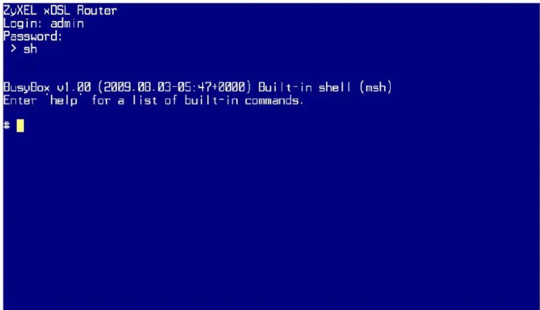
CPU usage
Command:
top
| Load average: 0.09, 0.07, 0.02 (State: S=sleeping R=running, W=waiting) | |||||||
| PID | USER | STATUS | RSS | PP10 | %CPU | %MEM | COMMAND |
| 3273 | admin | S | 528 | 1 | 3.5 | 1.8 | wps_monitor |
| ? | admin | SW | 0 | 1 | 0.9 | 0.0 | softirq-tasklet |
| 3587 | admin | R | 328 | 3586 | 0.1 | 1.1 | exe |
| 2147 | admin | S | 1584 | 126 | 0.0 | 5.4 | httpd |
| 272 | admin | S | 1436 | 126 | 0.0 | 4.9 | wlmngr |
| 127 | admin | S | 1404 | 126 | 0.0 | 4.8 | ssk |
| 3583 | admin | S | 652 | 126 | 0.0 | 2.2 | telnetd |
| 126 | admin | S | 600 | 60 | 0.0 | 2.0 | smd |
| 3584 | admin | S | 592 | 3583 | 0.0 | 2.0 | telnetd |
| 3261 | admin | S | 352 | 1 | 0.0 | 1.2 | bcmupnp |
| 60 | admin | S | 352 | 1 | 0.0 | 1.2 | sh |
| 3586 | admin | S | 340 | 3585 | 0.0 | 1.1 | exe |
| 3585 | admin | S | 308 | 3584 | 0.0 | 1.0 | sh |
| 1 | admin | S | 304 | 0 | 0.0 | 1.0 | init |
| 2145 | admin | S | 300 | 126 | 0.0 | 1.0 | syslogd |
| 146 | admin | S | 296 | 126 | 0.0 | 1.0 | dhcpd |
| 2146 | admin | S | 264 | 126 | 0.0 | 0.9 | klogd |
| 3271 | admin | S | 260 | 1 | 0.0 | 0.8 | lld2d |
| 581 | admin | S | 256 | 126 | 0.0 | 0.8 | dhcpc |
| 3269 | admin | S | 208 | 1 | 0.0 | 0.7 | nas |
(press Ctrl+C to exit)
Memory usage
Command:
# cat /proc/meminfo
| MemFree: | 7128 kB |
| Buffers: | 2444 kB |
| Cached: | 8456 kB |
| SwapCached: | 0 kB |
| Active: | 6396 kB |
| Inactive: | 6812 kB |
| SwapTotal: | 0 kB |
| SwapFree: | 0 kB |
| Dirty: | 0 kB |
| Writeback: | 0 kB |
| AnonPages: | 2320 kB |
| Mapped: | 2464 kB |
| Slab: | 5012 kB |
| SReclaimable: | 368 kB |
| SUnreclaim: | 4644 kB |
| PageTables: | 304 kB |
| NFS_Unstable: | 0 kB |
| Bounce: | 0 kB |
| CommitLimit: | 14800 kB |
| Committed_AS: | 5284 kB |
| UmallocTotal: | 1032148 kB |
| UmallocUsed: | 1516 kB |
| UmallocChunk: | 1029284 kB |
Current processes
Command:
ps
ps
PID Uid VmSize Stat Command
1 admin 304 S init
2 admin SW [softirq-high/0]
3 admin SW [softirq-timer/0]
4 admin SW [softirq-net-tx/]
5 admin SW [softirq-net-rx/]
6 admin SW [softirq-block/0]
7 admin SW [softirq-tasklet]
8 admin SW [softirq-sched/0]
9 admin SW [softirq-rcu/0]
10 admin SW[events/0]
11 admin SW[khelper]
12 admin SW[kthread]
20 admin SW[kblockd/0]
34 admin SW[pdffush]
35 admin SW[pdffush]
36 admin SW[kswapd0]
37 admin SW[aio/0]
48 admin SW[mtdblockd]
60 admin 352 S -sh
102 admin SW[bcmsw]
126 admin 620 S smd
127 admin 1404 S ssk
IGMP table
ps
PID Uid VmSize Stat Command
1 admin 304 S init
2 admin SW [softirq-high/0]
3 admin SW [softirq-timer/0]
4 admin SW [softirq-net-tx/]
5 admin SW [softirq-net-rx/]
6 admin SW [softirq-block/0]
7 admin SW [softirq-tasklet]
8 admin SW [softirq-sched/0]
9 admin SW [softirq-rcu/0]
10 admin SW[events/0]
11 admin SW[khelper]
12 admin SW[kthread]
20 admin SW[kblockd/0]
34 admin SW[pdffush]
35 admin SW[pdffush]
36 admin SW[kswapd0]
37 admin SW[aio/0]
48 admin SW[mtdblockd]
60 admin 352 S -sh
102 admin SW[bcmsw]
126 admin 620 S smd
127 admin 1404 S ssk
Command:
cat /proc/net/igmp
<h1 id="cat-procnetigmp">cat /proc/net/igmp</h1>
Idx Device : Count Querier Group Users Timer Reporter
1 lo : 0 V2
E0000001 1 0:02000000 0
8 eth0 : 1 V2
E0000001 1 0:02000000 0
9 eth1 : 1 V2
E0000001 1 0:02000000 0
10 eth2 : 1 V2
E0000001 1 0:02000000 0
11 eth3 : 1 V2
E0000001 1 0:02000000 0
12 wl0 : 1 V2
E0000001 1 0:02000000 0
13 br0 : 2 V2
EFFFFFFA 1 0:02000000 1
E0000001 1 0:02000000 0
14 ptm0 : 1 V2
E0000001 1 0:02000000 0
15 ptm0_1 : 1 V2
E0000001 1 0:02000000 0
#
Packets statistics
<h1 id="cat-procnetigmp">cat /proc/net/igmp</h1>
Idx Device : Count Querier Group Users Timer Reporter
1 lo : 0 V2
E0000001 1 0:02000000 0
8 eth0 : 1 V2
E0000001 1 0:02000000 0
9 eth1 : 1 V2
E0000001 1 0:02000000 0
10 eth2 : 1 V2
E0000001 1 0:02000000 0
11 eth3 : 1 V2
E0000001 1 0:02000000 0
12 wl0 : 1 V2
E0000001 1 0:02000000 0
13 br0 : 2 V2
EFFFFFFA 1 0:02000000 1
E0000001 1 0:02000000 0
14 ptm0 : 1 V2
E0000001 1 0:02000000 0
15 ptm0_1 : 1 V2
E0000001 1 0:02000000 0
#
Command:
cat /proc/net/dev
| # cat /proc/net/dev | |||||||||||
| Inter-1Receive | Transmit | ||||||||||
| face bytes packets error drop fifo frame compressed multicast bytes packe | |||||||||||
| ts errors drop fifo colls carrier compressed | |||||||||||
| lo: 766169 4635 0 0 0 0 0 0 0 766169 46 | |||||||||||
| 35 0 0 0 0 0 0 0 0 0 0 0 0 0 0 0 0 0 0 0 0 0 0 0 0 0 0 0 0 0 0 0 0 0 0 0 0 0 0 0 0 0 0 0 0 0 0 0 0 0 0 1271897 10940 0 0 0 0 0 0 0 0 0 0 9544823 144 | |||||||||||
| ifb0: 0 0 0 0 0 0 0 0 0 0 0 0 0 0 0 0 0 0 0 0 0 0 0 0 0 0 0 0 0 0 0 0 0 0 0 0 0 0 0 0 0 0 0 0 0 1271897.1271897.1271897.1271897.1271897.1271897.1271897.1271897.1271897.1271897.1271897.1271897.1271897.127 | |||||||||||
| dsl0: 0 0 0 0 0 0 0 0 0 0 0 0 0 0 0 0 0 0 | dsl0: | dsl0: | dsl0: | dsl0: | dsl0: | dsl0: | dsl0: | dsl0: | dsl0: | dsl0: | dsl0: |
| bcmsw: | bcmsw: | bcmsw: | bcmsw: | bcmsw: | bcmsw: | bcmsw: | bcmsw: | bcmsw: | bcmsw: | bcmsw: | bcmsw: |
| 61 | 61 | 61 | 61 | 61 | 61 | 61 | 61 | 61 | 61 | 61 | 61 |
| pktcmf_sw_sar: | |||||||||||
| pktcmf_sar_sw: | |||||||||||
| etho: | etho: | etho: | etho: | etho: | etho: | etho: | etho: | etho: | etho: | etho: | etho: |
| 29 | 29 | 29 | 29 | 29 | 29 | 29 | 29 | 29 | 29 | 29 | 29 |
| ethi: | |||||||||||
| 23 | 23 | 23 | 23 | 23 | 23 | 23 | 23 | 23 | 23 | 23 | 23 |
| eth2: | |||||||||||
| 25 | 25 | 25 | 25 | 25 | 25 | 25 | 25 | 25 | 25 | 25 | 25 |
Physical layer statistics
Command:
adslctl info --stats
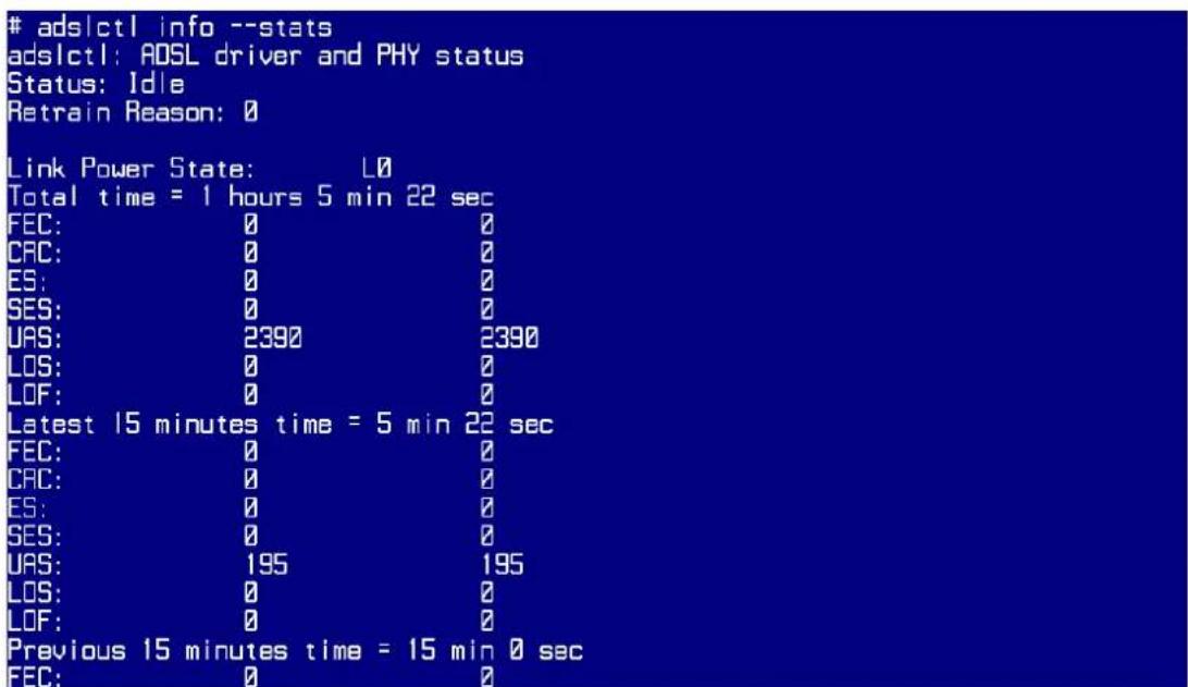
CLI Command List
The latest CI command list is available in release notes of every ZyXEL firmware release.
Please go to ZyXEL public WEB site http://www.zyxel.com/web/support_download.php to download firmware package (*.zip), you should unzip the package to get the release note in PDF format.


- P-870H/HW-51a v2
- Support Notes
- INDEX
- Application Notes......5
- General Application Notes
- Why use P-870HW-51aV2?
- Application Scenario
- FTTx - FTTC Solution
- FTTx - FTTB Solution
- Prologue
- Ethernet Connection
- TCP/IP Installation
- TCP/IP Configuration
- Access Application Notes
- Web GUI
- Telnet
- Internet Connection
- Bridge Mode
- a. Bridge Mode
- IPoE Mode
- Scenario:
- b. IPoE Mode
- PPPoE Mode
- c. PPPoE Mode
- IGMP Multicast Proxy
- IP Multicast Introduction
- IGMP Multicast Proxy Configuration
- a. IGMP Multicast Proxy
- Protocol Based Scenario
- WAN Configuration
- a. Internet Service
- b. IPTV Service
- Click Next
- Select Enable IGMP Multicast Proxy
- VLAN Based Scenario
- Quality of Service
- QoS configuration
- a. Enable QoS
- b. Configure the Video traffic.
- TR069 – Remote Firmware Upgrade
- TR069 Configuration
- NAT Portforwarding
- NAT/Multi-NAT Introduction
- One to One
- Many to One
- Many to Many Overload
- Many to Many No Overload
- Environment
- Port Forwarding Configuration
- DMZ Host Configuration
- a. Create a DMZ host.
- IP Filter
- IP Filter Configuration
- a. Make sure that Firewall is enable in the WAN
- Show the IP configuration of notebook:
- Configuration of Accepting Incoming Traffic
- b. Configure the IP Filtering Setup.
- LAN Connection
- IP Alias Introduction
- IP Alias Configuration
- a. IP Alias
- Maintenance Log
- Internal Maintenance
- Date/Time Severity System Message
- Remote Maintenance
- a. Activate the Maintenance Log.
- Maintenance Tool
- Maintenance Procedure
- a. Upload Firmware.
- b. Save Configuration.
- Wireless Application Notes
- IEEE 802.1x Introduction
- Authenticator:
- Supplicant:
- Authentication Server:
- • Authentication Port State and Authentication Control
- • Re-Authentication
- • EAPOL (Extensible Authentication Protocol over LAN)
- EAPOL Exchange between 802.1x Authenticator and Supplicant
- Wi-Fi Protected Access Introduction
- Wireless Configuration (P-870H-51aV2 does not support wireless features)
- a. Wireless Setup.
- b. Wireless Setup Hiding the SSID.
- c. Wireless Setup Using "Auto Generate Key".
- WPS Application Notes
- What is WPS?
- PIN Method:
- PBC Method:
- WPS configuration
- a. WPS Setup
- b. WPS Station Setup
- Product FAQ
- How do I know I am using PPPoE?
- Why does my provider use PPPoE?
- Which Internet Applications can I use with the device?
- How can I configure the device?
- What network interface does the device support?
- What can we do with the device?
- What DHCP capability does the device support?
- How do I used the reset button, more over what field of parameter will be reset by reset button?
- What network interface does the new device series support?
- How does the device support TFTP?
- Can the device support TFTP over WAN?
- How fast can the data go?
- What is Multi-NAT?
- When do I need Multi-NAT?
- What IP/Port mapping does Multi-NAT support?
- Server
- What is the difference between SUA and Multi-NAT?
- What is BOOTP/DHCP?
- What is DDNS?
- When do I need DDNS service?
- Wireless FAQ
- What is a Wireless LAN?
- What are the advantages of Wireless LANs?
- a. Mobility:
- b. Installation Speed and Simplicity:
- c. Installation Flexibility:
- d. Reduced Cost-of-Ownership:
- e. Scalability:
- What are the disadvantages of Wireless LANs?
- Where can you find wireless 802.11 networks?
- What is an Access Point?
- What is IEEE 802.11?
- What is 802.11b?
- How fast is 802.11b?
- What is 802.11a?
- What is 802.11g?
- Is it possible to use products from a variety of vendors?
- What is Wi-Fi?
- What types of devices use the 2.4GHz Band?
- Does the 802.11 interfere with Bluetooth devices?
- Can radio signals pass through walls?
- Factors of interference:
- Solution :
- What's the difference between a WLAN and a WWAN?
- What is Ad Hoc mode?
- What is Infrastructure mode?
- How many Access Points are required in a given area?
- What is Direct-Sequence Spread Spectrum Technology – (DSSS)?
- What is Frequency-hopping Spread Spectrum Technology – (FHSS)?
- Do I need the same kind of antenna on both sides of a link?
- Why the 2.4 Ghz Frequency range?
- What is Server Set ID (SSID)?
- What is an ESSID?
- How do I secure the data across an Access Point's radio link?
- What is WEP?
- What is the difference between 40-bit and 64-bit WEP?
- What is a WEP key?
- A WEP key is a user defined string of characters used to encrypt and decrypt data?
- Can the SSID be encrypted?
- By turning off the broadcast of SSID, can someone still sniff the SSID?
- What are Insertion Attacks?
- What is Wireless Sniffer?
- What is the difference between Open System and Shared Key of Authentication Type?
- What is 802.1x?
- What is the difference between No authentication required, No access allowed and Authentication required?
- What is AAA?
- What is RADIUS?
- What is WPA?
- What is WPA-PSK?
- Trouble Shooting
- How to enter the "Shell mode"
- CPU usage
- top
- Current processes
- ps
- IGMP table
- cat /proc/net/igmp
- Packets statistics
- cat /proc/net/dev
- Physical layer statistics
- adslctl info --stats
- ads|ctl info --stats
- CLI Command List
Marke : ZYXEL
Modell : P-870H
Kategorie : Router