
DY365 4CE - Elektrisches Relais ABB - Kostenlose Bedienungsanleitung
Finden Sie kostenlos die Bedienungsanleitung des Geräts DY365 4CE ABB als PDF.


| Produkttyp | Fernschaltaktor |
| Modell | DY365 4CE |
| Code | 2CSM221181R1000 |
| Spannungsversorgung | 12/24 V AC/DC (-15%/+10%) 50/60 Hz |
| Anzahl Relais | 4 (Schließer) |
| Relaiskontaktbelastbarkeit | 8 A / 250 V AC |
| Betriebstemperatur | 0 °C bis +50 °C |
| Lagertemperatur | -25 °C bis +70 °C |
| Schutzart | IP20 (IP40 bei Einbau in Schaltschrank) |
| Abmessungen (B × H × T) | 72 mm × 87 mm × 65 mm |
| Gewicht | ca. 0,2 kg |
| Montage | 4 DIN-Module (Hutschiene) |
| Schnittstelle | I/O-Erweiterungsport für DY365 Schalter |
| Konfiguration | Über SET-Taste (3 s drücken) und DY365 Schalter |
| Anzeigen | Grüne LED (Betrieb), rote LEDs (Relaisstatus) |
| Normen | EN 60730-1, EN 301 489-1/3, EN 300 220-3; 2014/35/EU, 2014/30/EU |
| Einbau | Nur durch Fachpersonal gemäß Schaltplan |
| Reinigung | Nicht vorgesehen; Gerät ist wartungsfrei |
Häufig gestellte Fragen - DY365 4CE ABB
Benutzerfragen zu DY365 4CE ABB
0 Frage zu diesem Gerät. Beantworten Sie die, die Sie kennen, oder stellen Sie Ihre eigene.
Eine neue Frage zu diesem Gerät stellen
Laden Sie die Anleitung für Ihr Elektrisches Relais kostenlos im PDF-Format! Finden Sie Ihr Handbuch DY365 4CE - ABB und nehmen Sie Ihr elektronisches Gerät wieder in die Hand. Auf dieser Seite sind alle Dokumente veröffentlicht, die für die Verwendung Ihres Geräts notwendig sind. DY365 4CE von der Marke ABB.
BEDIENUNGSANLEITUNG DY365 4CE ABB
© Copyright 2019 ABB S.P.A. All rights reserved.
We reserve the right to make technical changes or modify
the contents of this document without prior notice.
DY365 4CE
Installation Manual
Dimensions (mm)


Connection diagram

Description
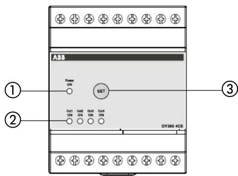
① Green LED for operating status signaling
② Red LEDS for relay status signaling
③ SET BUTTON for channels programming and resetting
User manual
DY365 4CE REMOTE ACTUATOR
Read all instructions carefully
- The DY365 4CE remote actuator is a four-relay electronic device that receives the command signals from the DY365 switch via I/O extension ports.
It performs actions of 1B type and is intended to operate in a domestic and similar environment with overvoltage category III and normal pollution degree (EN 60730-1).
SAFETY WARNINGS
During product installation and operation it is necessary to observe the following instructions:
1) The device must be installed by a qualified person
2) Before accessing the terminals, make sure that the leads are not live
3) Do not power the device if any part of it is damaged
4) Connect the product following the diagrams described in this manual
5) In the electrical system upstream of the device must be installed a switch and a protection device against the overcurrents.
6) The product must be installed and activated in compliance with current electric systems standards.
7) After installation inaccessibility to the terminals without using dedicated tools must be guaranteed.
Code Model Description
2CSM221181R1000 DY365 4CE 4-channel remote actuator
TECHNICAL FEATURES
• Power supply: 12/24 V AC/DC (-15%/+10%) 50/60 Hz
• 4 relays normally open 8A / 250 V AC
- I/O extension port for connection to the DY365 switch
- Operating temperature: 0 ÷ +50^ C
• Storage temperature: -25 ÷ +70 °C
- Container: 4 DIN modules
- Protection degree: IP20 (IP40 when correctly installed in the electrical panel)
OPERATION
- When switched on, the red LEDs emit 2 flashes lasting half a second (switch-on sequence).
- Once the switch-on sequence is completed, the green LED is lit to indicate normal device operation and the red LEDs are turned on/off to indicate the corresponding status of the 4 channels (on = ON).
Channels configuration
- During normal operation, press and hold the SET button for at least 3 seconds to enter in configuration mode. In this mode the green LED is off while the red LED corresponding to the relay to be configured flashes.
- To select the relay to be associated with the channel of DY365 switch, press the SET button until the red LED for the relay to be configured flashes.
- Once the channel is selected, the actuator remains in configuration mode for 60 seconds: activate the channel configuration on the DY365 switch. To activate the channel configuration, see the DY365 switch user manual.
- Once the relay configuration is complete, the actuator resumes normal operation
- To cancel the configuration of a channel, enter the configuration mode, select the channel with the SET button (relative red LED flashing), then press the SET button for at least three seconds until the green LED lights up again. Each new configuration cancels the previous configuration
REFERENCE STANDARDS
Compliance with Community Directives:
2014/35/EU (LVD)
2014/30/EU (EMCD)
is declared in reference to the harmonized Standards:
■ EN 60730-1
■ EN 301 489-1/3 and EN 300 220-3
Marke : ABB
Modell : DY365 4CE
Kategorie : Elektrisches Relais