
RX-CW200 - Hi-Fi-System PANASONIC - Kostenlose Bedienungsanleitung
Finden Sie kostenlos die Bedienungsanleitung des Geräts RX-CW200 PANASONIC als PDF.


Benutzerfragen zu RX-CW200 PANASONIC
0 Frage zu diesem Gerät. Beantworten Sie die, die Sie kennen, oder stellen Sie Ihre eigene.
Eine neue Frage zu diesem Gerät stellen
Laden Sie die Anleitung für Ihr Hi-Fi-System kostenlos im PDF-Format! Finden Sie Ihr Handbuch RX-CW200 - PANASONIC und nehmen Sie Ihr elektronisches Gerät wieder in die Hand. Auf dieser Seite sind alle Dokumente veröffentlicht, die für die Verwendung Ihres Geräts notwendig sind. RX-CW200 von der Marke PANASONIC.
BEDIENUNGSANLEITUNG RX-CW200 PANASONIC
Operating Instructions
Mode d'emploi Bedienungsanleitung Gebruiksaanwijzing Bruksanvisning Brugsvejiedning Istruzioni per l'uso
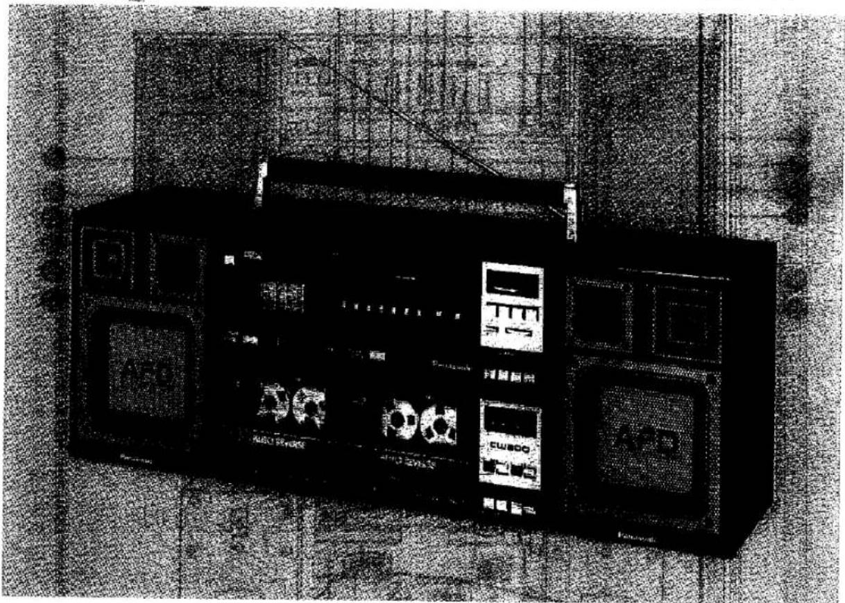
Portable Stereo Component System
MODEL NO. RX-CW200L
natural_image
Black-and-white photo of a portable electronic device with front panels and buttons, placed on a textured surface (no visible text or symbols)Panasonic
Read these instructions completely before operating this set.
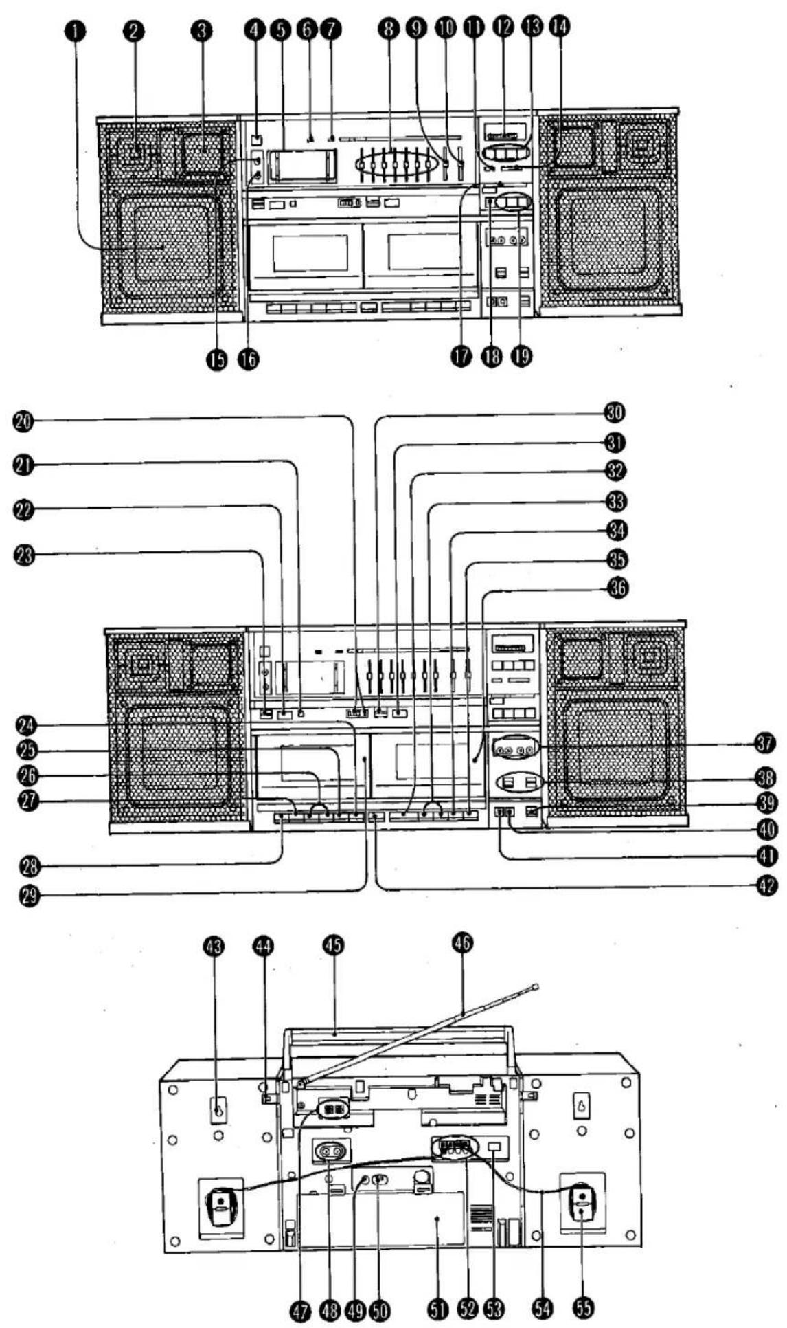
LOCATION OF CONTROLS
(Refer to page 2.)
① Speakers (Woofer)
? Speakers (Tweeter)
③ Speakers (Squawker)
④ Operation Switch (OPERATION)
⑩ Spectrum Analyzer (SPECTRUM ANALYZER)
⑥ Operation/Battery Check Indicator (OPR/BATT)
7 FM Stereo Indicator (FM STEREO)
⑧ Graphic Equalizer/Frequency Distribution Equalizer Controls (GRAPHIC EQUALIZER/ F.D.EQ)
⑨ Mixing Level Control (MIXING LEVEL)
⑩ Balance Control (BALANCE)
⑪ FM Mode Selector (FM MODE)
⑫ Tuning Control (TUNING)
13 Band Selector (BAND)
⑭ Fine Tuning Control (FINE TUNING)
⑮ Mixing Microphone Jack (MiX.MIC)
16 Headphones Jack (PHONES)
When using the headphones (EAH-S10, optional), avoid listening to sound for a long period of time at excessive volume levels, which may injure your ears.
⑰ Volume Control (VOLUME)
18 Equalizer Mode Selector (EQUALIZER MODE)
19 Function Selector (FUNCTION)
TAPE 1 (For Recording and Playback)
Tape 1 Counter and Reset Button (TAPE①COUNTER)
② Built-in Microphone (MIC)
22 Direction Button (DIRECTION)
23 Reverse Mode Selector (REVERSE MODE)
24 Pause Button (II PAUSE)
25 Stop/Eject Button (■/▲ STOP/EJECT)
26 Fast/Cue Buttons ( ◀◀·▶▶ FAST/CUE)
Playback Button (▶ PLAY)
Record Button (RECORD)
29 Cassette Compartment
TAPE 2 (For Playback)
30 Reverse Mode Selector (REVERSE MODE)
31 Direction Button (DIRECTION)
32 Playback Button (▶PLAY)
33 Fast/TPS Buttons (◀◀·▶▶ FAST TPS)
34 Stop/Eject Button (■/▲STOP/EJECT)
35 Pause Button (II PAUSE)
36 Cassette Compartment
37 Direction Indicators (DIRECTION)
38 Tape Selectors (TAPE SELECTOR)
39 Editing Mode Selector (EDITING)
40 Dolby ^※ NR Switch (DOLBY NR)
41 Relay Playback Switch (RELAY PLAY)
42 One Touch Editing Button (ONE TOUCH EDITING)
43 Speaker Wall Mounts
Speaker Release Levers (RELEASE)
45 Detachable Carrying Handle
46 Telescopic Antenna
47 External Antenna Terminals (FM ANT/SW ANT)
48 CD/Line Input Jacks (CD/LINE IN)
49 DC Input Jack [DC IN 13.2V (12-15V) ⊕ ⊙ ⊕]
50 AC Socket (AC IN\~)
⑤ Battery Compartment
52 Speaker Terminals (SPEAKER IMP 8Ω ONLY)
53 Beat Proof Switch (BEAT PROOF)
54 Speaker Cables
55 Speaker Cable Compartments
* 'Dolby' and the double-D symbol are trademarks of Dolby Laboratories Licensing Corporation. Noise Reduction System manufactured under license from Dolby Laboratories Licensing Corporation.
IMPORTANT (FOR U.K.)
The wires in this mains lead are coloured in accordance with the following code:
Blue: Neutral Brown: Live
As the colours of the wires in the mains lead of this apparatus may not correspond with coloured markings identifying the terminals in your plug, proceed as follows:
- The wire which is coloured blue must be connected to the terminal which is marked with the letter N or coloured black.
- The wire which is coloured brown must be connected to the terminal which is marked with the letter L or coloured red. Notes:
- Disconnect the mains plug from the supply socket when not in use.
- Do not remove cover. Live parts inside.
PRECAUTIONS
- If the set is not used for a long period of time or is used only from an AC power source, remove all the batteries to prevent potential damage due to possible battery leakage.
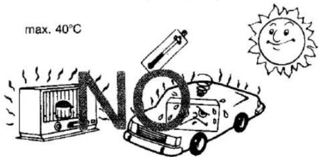
- Avoid using or placing the unit near sources of heat. Do not leave it in an automobile exposed to direct sunlight for a long time with the doors and windows closed as this may deform the cabinet.
- Avoid cuts, scratches, or poor connections in the AC power cord, as they may result in possible fire or electric shock hazard. Also, excessive bending, pulling or splicing of the cord should be avoided.
- Do not unplug the AC power cord by pulling on the cord. To do so may cause premature failure or shock hazard.
- Do not operate the set on AC power in bathroom, as a potential shock hazard may result.
- When not in use, disconnect the AC power cord from the AC power outlet.
- The Operation Switch does not separate entire unit from mains even if in "OFF" position.
text_image
max. 40°C NTo Prevent Possible Damage to This Unit
- Load new batteries with their polarities (⊕ and ⊖) aligned correctly.
- Do not apply heat to batteries, or internal short-circuit may occur.
-
If this unit is not to be used for a long period of time, or used on AC mains supply, remove all batteries and store them in a cool and dry place.
-
Remove spent batteries immediately and dispose of them.
- Do not use old and new batteries together. Also never use an alkaline battery with a manganese battery.
CASSETTE TAPES
Use only good-quality tapes up to the length of C-90. Do not use C-120 tapes with this unit because these tapes can easily become broken or stretched if not used with extreme care and may get tangled with the Capstans and Pressure Rollers.
Note:
Cassettes, both recorded and unrecorded, should not be stored in locations with high temperature, high humidity or direct sunlight. Never place a recorded cassette near a magnetic source, such as a magnet or a TV set as this may affect tape performance.
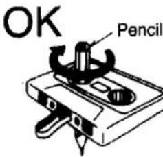
If the tape loosens, take up the slack by turning the reel in the proper directions.
text_image
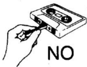
OK PencilDo not handle, or pull the tape out of the cassette.
text_image
NOPOWER SOURCE
■ Battery Operation
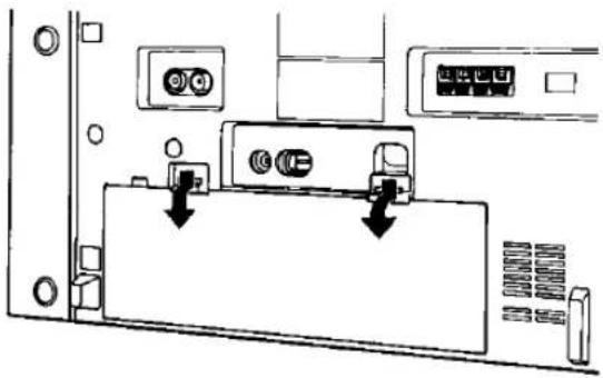
- Open the Battery Compartment cover as shown in the figure.
text_image
Diagram showing a device rear panel with labeled ports and connectors, including a switch and battery icon.- Insert 10 "D" size (Panasonic UM-1 or equivalent) batteries into the Battery Compartment, making sure that the proper polarities are maintained, and that the batteries are installed in the specified numerical order.

text_image
Upper shelf 5 4 10 9 - Hole for battery removal Lower shelf 2 3 1 6 8 7- Replace the compartment cover.
- Battery life
When the batteries are weak, the tape speed will slow down, the sound will become distorted, and the volume will decrease.
- Press the Operation Switch to "ON".
- Press the TAPE Button (FUNCTION).
- Press the Playback Button.
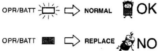
- If the Operation/Battery Check Indicator goes out or dims, replace all batteries with new ones.
text_image
OPR/BATT → NORMAL OK OPR/BATT → REPLACE NONote:
When batteries are weak, the Cassette Compartment cover may not open by pressing the Stop/Eject Button.
In this case, replace all the batteries with new ones.
■ AC Power Operation
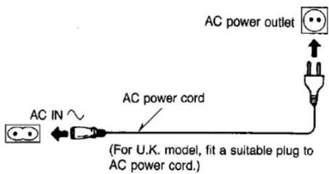
Connect the included AC power cord to the AC Socket in the unit and your household AC power outlet.
text_image
AC power outlet AC IN ~ AC power cord (For U.K. model, fit a suitable plug to AC power cord.)Note:
To operate on battery power, unplug the AC power cord from the household AC power outlet and the AC Socket on the unit.
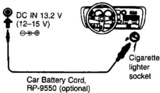
■ Car Battery Operation
- Insert the plug of the car battery cord into the DC Input Jack.
- Plug the opposite end of the cord into the cigarette lighter socket in your car.
Upon plugging the car battery cord into the DC Input Jack, the unit will automatically switch from internal battery to car battery operation.
text_image
DC IN 13.2 V (12–15 V) Car Battery Cord, RP-9550 (optional) Cigarette lighter socketSPEAKER SYSTEM CONNECTION
This unit can be used as a one-piece portable stereo radio cassette recorder, or a three-piece component system, by attaching or detaching the speaker system.
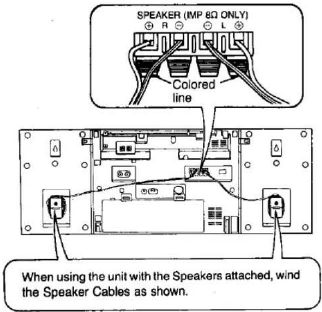
- Before attaching or detaching the Speakers, be sure to disconnect the Speaker Cables from the Speaker Terminals.
- Be sure to set the Operation Switch to "OFF" before connecting the Speaker Cables.
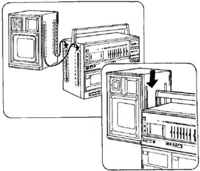
■ Attaching the Speakers
- Align the Speaker with the main unit as shown in the figure, interlock the grooves and press down.
natural_image
Diagram showing two server racks connected via a cable, with one panel open and another showing internal components (no text or symbols)-
Connect the speaker terminal cord end, marked by a colored line, to the ⊕ speaker terminal and then in turn to the appropriate speaker.
-
Be sure to twist the center conductors of the speaker cords.
- Stereo effect and tonal quality are likely to be impaired if the polarities (⊕ and ⊖) are not properly maintained.
text_image
SPEAKER (IMP 8Ω ONLY) Colored line When using the unit with the Speakers attached, wind the Speaker Cables as shown.Note:
Since a strong magnet is used for the Speaker, keep magnetized commuter passes, tickets or personal credit cards, recorded tapes, watches, etc. away from the set. The speaker magnet in the set may damage them.
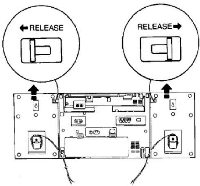
■ Detaching the Speakers
- Unlock the Speaker Release Levers by pulling them in the direction shown below, and slide up the each Speaker.
text_image
RELEASE RELEASE- Connect the Speaker Cables to the Speaker Terminals.
■ Speaker Wall Mounts
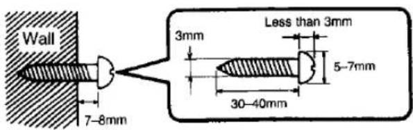
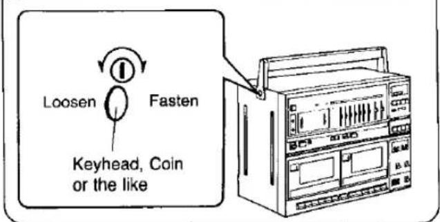
- Drive one screw into the wall for each Speaker, as shown in the figure. Insure that both the screws and the wall can support a 20 kg load.
- Mount the Speakers to the wall by hanging the Speaker Wall Mounts (built into the speaker cabinet) onto the screws.
text_image
Wall 7-8mm 3mm Less than 3mm 5-7mm 30-40mmDetachable Carrying Handle
text_image
Loosen Fasten Keyhead, Coin or the like- Set the Operation Switch to "ON".
• The Operation/Battery Check Indicator will light. - Press the TUNER Button (FUNCTION).
-
Set the Band Selector to the desired radio band.
-
Tune in your favorite station using the Tuning Control. • The frequency components of the signal being received will be indicated by the Spectrum Analyzer.
-
Set the FM Mode Selector to "STEREO" or "MONO".
-
Set the Equalizer Mode Selector to the desired mode G.EQ; Graphic Equalizer functions. F.D.EQ; Frequency Distribution Equalizer functions. (Refer below for the operation of the Graphic Equalizer and Frequency Distribution Equalizer.)
-
Adjust the Volume, Balance and Graphic Equalizer/Frequency Distribution Equalizer Controls to the desired settings.
-
The radio can be turned off by setting the Operation Switch to "OFF".
Notes:
- If the FM Mode Selector is set to "STEREO" and the desired broadcast is tuned, the FM muting circuit functions in this unit.
- To receive FM stereo broadcasts, set the FM Mode Selector to "STEREO". The FM Stereo Indicator will light during stereo broadcasts.
- If FM stereo reception is poor (excessive noise, FM Stereo Indicator flickers), set the FM Mode Selector to "MONO". This will reduce the noise and provide clear reception; however, the broadcast will not be heard in stereo.
- Once the unit is tuned to receive FM stereo broadcasts, the FM Stereo Indicator will remain lit at all positions of the Function Selector (except when the power circuit is cut off).
■ Spectrum Analyzer and Graphic Equalizer
Set the Equalizer Mode Selector to "G.EQ".
The frequency components of the source signal are displayed, divided into five frequency bands (100 Hz, 330 Hz, 1 kHz, 3.3 kHz, 10 kHz).
In addition, different sound bands [100 Hz, 250 Hz, 500 Hz, 1 kHz, 2.5 kHz, 5 kHz, 10 kHz] can be adjusted to suit your taste using the controls of the Graphic Equalizer, while the spectrum of the resulting sound is displayed by the Spectrum Analyzer.
- Positioning the control to the “+” side of the detent (center) will amplify the corresponding frequency band; the “−” side will attenuate it.
■ Frequency Distribution Equalizer
Set the Equalizer Mode Selector to "F.D.EQ".
By dividing the each frequency sound into the right and left Speakers, quasi-stereo sound can be made from the monaural source.
- If setting the Frequency Distribution Equalizer Controls to "0", the monaural sound can be heard from the center position.
- If moving the Frequency Distribution Equalizer Controls to "LEFT" or "RIGHT", the each frequency sound can be heard from the corresponding Speaker. So you can hear the monaural sounds as if it were stereo.
■ Fine Tuning Control
For short-wave broadcasts, tune to the approximate frequency with the Tuning Control, and then use the Fine Tuning Control for more precise tuning.
Note:
When using the Tuning Control, be sure to set the Fine Tuning Control pointer to the center position.
Antennas
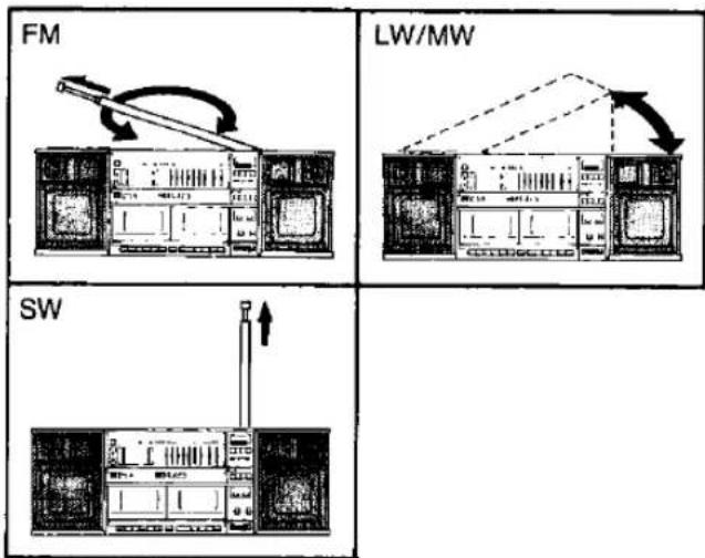
FM:
- Pull out the Telescopic Antenna and adjust its length and angle for optimum reception.
LW/MW:
- The sensitive ferrite core antenna inside the set will provide excellent LW/MW reception in most areas. For optimum reception, turn the set in the direction which gives the best results since the ferrite core antenna is directional.
SW:
- Extend the Telescopic Antenna fully, keep it vertical.
flowchart
graph TD
    A["FM"] --> B["Switch"]
    B --> C["Load"]
    D["LW/MW"] --> E["Switch"]
    E --> F["Load"]
    G["SW"] --> H["Switch"]
    H --> I["Load"]
RADIO
• To further improve reception (FM and SW)
FM
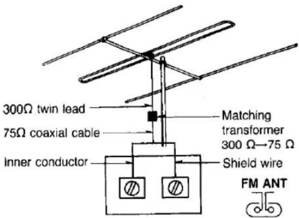
- To improve reception or receive very distant stations, connect an FM antenna (FM dipole antenna, TV antenna) to the External Antenna Terminals, as shown in the figure.
text_image
300Ω twin lead 75Ω coaxial cable Inner conductor Matching transformer 300 Ω→75 Ω Shield wire FM ANTNote:
If the antenna is connected with 75Ω coaxial cable instead of 300Ω twin lead, the matching transformer is not required.
SW
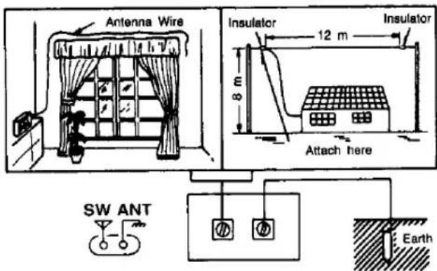
- To improve reception, connect a length of wire, to serve as an antenna, to the External Antenna Terminals, as shown in the figure.
text_image
Antenna Wire Insulator 12 m Insulator 8 m Attach here SW ANT EarthNote:
An antenna for the SW bands can be constructed from a length of wire. A long length of wire will provide better results; however, a short length of wire is also suitable.
CAUTION:
External Antenna Terminals are not available on the model sold in West Germany and in Italy.
TAPE PLAYBACK
This unit has a dual cassette system, which means that a tape can be played back with both Tape 1 and Tape 2.
■ Single Tape Playback
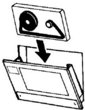
- Open the Cassette Compartment cover by pressing the Stop/Eject Button. Insert the cassette as shown in the figure, and then close the Cassette Compartment cover.
natural_image
Diagram showing a device being folded into a rectangular box, with a magnified view of the disc (no text or symbols present)Note:
Make sure the exposed part of the cassette tape is face down. If it is upside down, the Cassette Compartment cannot be closed, do not try to force it shut.
- Set the Operation Switch to "ON".
• The Operation/Battery Check Indicator will light.
-
Press the Tape Button (FUNCTION).
-
Set the Tape Selector, as shown in the table below, according to the cassette tape used.
Tape Selector Settings
| Tape Selector Position | Tape |
| METAL (P.B)/CrO_2 | Metal tape (for playback only) |
| High bias chromium tape or equivalent | |
| NORMAL | Low bias ferric oxide tape |
-
Set the Dolby Noise Reduction Switch to "IN" to playback a tape recorded with Dolby Noise Reduction. For other tapes, set the switch to "OUT".
-
Set the Reverse Mode Selector to the desired mode. [Tape 1]
: One-side playback mode
: Repeat two-side playback mode
[Tape 2]
D: Two-side playback mode
: One-side playback mode
-
Set the Equalizer Mode Selector to the desired mode. (Refer to page 7 "Graphic Equalizer" and "Frequency Distribution Equalizer".)
-
Press the Playback Button to begin tape playback to the forward direction.
• The Direction (FWD) Indicator will light.
- You can select the side for playback by pressing the Direction Button. In this case, the Direction Indicators show the tape direction.
- The frequency components of the tape being played back will be displayed by the Spectrum Analyzer.
- Adjust the Volume, Balance and Graphic Equalizer/Frequency Distribution Equalizer Controls to desired settings.
- To stop the playback, press the Stop/Eject Button.
- Set the Operation Switch to "OFF" to turn the unit off.
Notes:
- During playback, if the Band Selector is pressed mistakenly, the playback sound will be temporarily interrupted.
- When not using the Automatic Playback Relay, be sure to set the Relay Playback Switch to "OFF".
■ Automatic Playback Relay (Tape 2 to Tape 1)
When Tape 2 playback (one-side or two side) has finished, Tape 1 playback starts automatically.
- Insert the playback tapes into Tape 1 and Tape 2.
- Set the Relay Playback Switch to "ON".
- Set the Reverse Mode Selectors (Tape 1 and Tape 2) to the desired position.
- Press the Tape 2 Playback Button.
- Press the Tape 1 Playback Button.
■ Full Auto-Stop Mechanism
During playback, recording, fast forward, or rewind when the tape comes to its end, the tape travel will automatically stop. During playback, if the Reverse Mode Selector is set to "Z" position, the Automatic Stop System does not function.
Note:
If the Operation Switch is "ON", the unit will not be turned off even after the Auto-Stop mechanism has operated. In this case, be sure to set the switch to "OFF" to turn the unit off.
■ Pause Button
The Pause Button can be used to temporarily stop the tape from moving during recording or playback.
Before beginning a recording, first press and lock the Pause Button. Then, press the Record Button. (The tape will not move.) When ready to record, press the Pause Button to release it. This will start tape movement for immediate recording.
Note:
Do not use the Pause Button to stop the tape for a long period of time.
The unit is not turned off when the Pause Button is pressed. Always use the Stop/Eject Button to turn the unit off.
■ Fast Forward and Rewind
The tape will rapidly advance in the forward or reverse direction when one of the Fast Buttons is pressed.
Note:
Do not press the Playback Button during fast forward or rewind, as this may jam the tape. Always press the Stop/Eject Button first; between functions.
■ "Cue" and "Review" (Tape 1)
(◀◀·▶▶ FAST/CUE)
If one of the Fast/Cue Buttons is partially pressed and held down during playback, the recorded sound on the tape can be monitored at a fast speed. When the button is released, playback will resume.
"▶▶" means cue and "◀◀" means review operation in the forward mode. In the reverse mode, each button functions the opposite operation.
Dolby NR
This unit includes Dolby Noise Reduction which reduces tape noise to a remarkable degrees.
Briefly, the system works as follows:
At low sound levels (where tape noise is most noticeable), the high frequency (treble) portion of the sound is recorded at a higher level.
During playback, the same high frequency portion of the sound is played back at a lower level. Since tape noise is introduced during recording and consists mainly of high frequencies, the tape noise is also reduced during playback. In effect, the sound is boosted during recording, then the sound along with the tape noise is reduced during playback. The result is unaltered sound with reduced tape noise.
- Tape 1 Counter and Reset Button
The digits return to "000" when the Reset Button is pressed. The digits advance with the tape to provide a reference to quickly find a desired portion of tape.
AUTO REVERSE PLAYBACK
This unit is equipped with an auto reverse function that allows you to perform one-side playback, two-side playback (Tape 2) or repeat two-side playback (Tape 1).
- If the Direction Button is pressed during the tape playback, the reverse side of the cassette tape can be heard.
■ One-side playback (To listen to side 1 or side 2)
| Reverse Mode Selector | Tape Direction | Indicators |
| [Tape 1]REVERSE MODE[IMAGE][Tape 2]REVERSE MODE[IMAGE] | 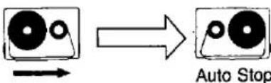 | REV FWD◀ ◇- |
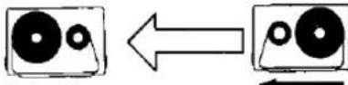 Auto Stop Auto Stop | REV FWD◀ ◇- ▶ |
■ Two-side playback (To listen to side 1 and side 2) [Tape 2 only]
| Reverse Mode Selector | Tape Direction | Indicators |
| [Tape 2]REVERSE MODE | Make sure to start from forward direction (side 1).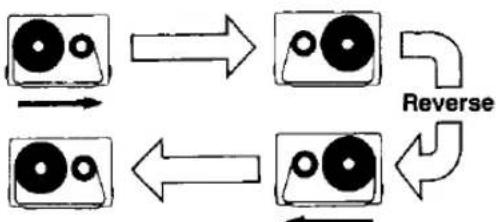 If playback is started from reverse direction (side 2), side 2 will be played, after which auto stop will operate. If playback is started from reverse direction (side 2), side 2 will be played, after which auto stop will operate. | REV FWD◄► REV FWD◄► |
■ Repeat two-side playback (To listen to side 1 and side 2 repeatedly) [Tape 1 only]
| Reverse Mode Selector | Tape Direction | Indicators |
| [Tape 1]REVERSE MODE | 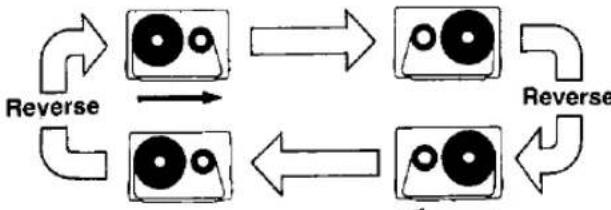 Playback will be repeated until the Stop/Eject Button is pressed. Playback will be repeated until the Stop/Eject Button is pressed. | REV FWD▲▲▲▲REV FWD▲▲▲ |
Notes:
- Auto reverse does not function during recording. Recording can be made only in the forward direction.
- During playback in the reverse direction, if you press the Stop/Eject Button to stop the tape movement, and then press the Playback Button again, playback will always begin in the forward direction.
TPS (TAPE PROGRAM SENSOR) (TAPE 2)
The Tape Program Sensor system can be set to automatically play back a predetermined selection on a recorded cassette tape.
Procedure:
- Follow the same procedure as described in steps 1–9 of "TAPE PLAYBACK" on page 8–9.
- Press the one of the Fast/TPS Buttons (◀◀ or ▶▶).
| IndicatorsFast/TPSButtons | TAPE2REV FWD◀ ▶ | TAPE2REV FWD◀ ▶ |
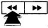 | PresentProgram | NextProgram |
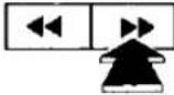 | NextProgram | PresentProgram |
- When the start of the desired selection is reached, playback will start.
In the following instances the Tape Program Sensor system may not operate normally. This does not, however, indicate a failure.
- With tapes of conversations having a great many gaps in the dialog.
- With tapes having tracks with extremely low sound levels.
- With tapes having portions among the tracks where no sound has been recorded.
- With tapes having intervals of less than 4 seconds long.
- With tapes having a high level of noise during the intervals.
- When less than 10 seconds separate the program you are listening to and the next program when you want to move on to listen to the next program.
- During high-speed editing from Tape 2 to Tape 1.
RECORD PREVENTION TABS
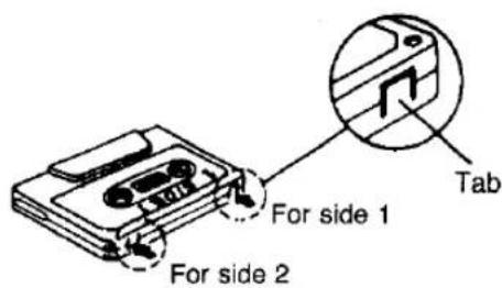
Cassettes are provided with plastic tabs (as illustrated) to prevent accidental erasing of a recording.
Recordings can be made only when the tab is intact. There is one tab for each side (track) of the tape. To preserve a valuable recording, the tab(s) should be broken off with a small screwdriver.
If you want to record on a track whose tab has already been broken off, use cellophane tape to cover the hole, and record.
text_image
For side 1 For side 2 Tab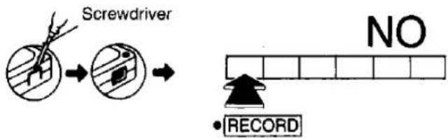
text_image
Screwdriver NO • RECORD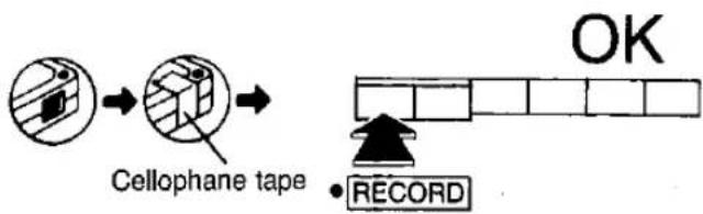
flowchart
graph LR
    A["Initial Cellophane tape"] --> B["Step 1: Cellophane tape with label"]
    B --> C["Step 2: Record with arrow pointing to 'OK'"]
    C --> D["End: Block with horizontal bar and number of squares"]
- This unit has an Automatic Level Control (the recording level is automatically adjusted.)
- This unit has a variable-sound monitor system, which means that the monitor sound can be adjusted using the Volume Control without affecting the recording itself.
- Recording can be made only in the forward direction.
Your attention is drawn to the fact that recording pre-recorded tapes or discs on other published or broadcast material may infringe copyright laws.
■ Recording Radio Broadcasts
- Follow the procedure described in "RADIO" on the page 7-8.
- Insert the cassette into the Tape 1 Cassette Compartment.
- Set the Tape 1 Tape Selector according to the cassette tape used.
- Set the Dolby Noise Reduction Switch to "IN", if this feature is desired.
- Press the Record Button and the recording will begin.
- To stop the recording, press the Stop/Eject Button.
- Set the Operation Switch to "OFF" to turn the unit off.
Note:
The Graphic Equalizer or Frequency Distribution Equalizer does not function when recording. Only the monitor sound is affected.
- Beat Proof Switch
When an LW, MW or SW broadcast is recorded, the Beat Proof Switch can be used to reduce unwanted "beat" signals (whistle) which are sometimes present. Set the switch to whichever position best reduces these "beat" signals.
■ Recording through the Built-in Microphone
The condenser microphone in this unit is omni-directional (all directions), so that recordings can be made from any direction.
- Set the Operation Switch to "ON".
- Press the TAPE Button (FUNCTION).
- Set the Editing Mode Selector to "OFF/BUILT IN MIC".
- Follow the procedure described in steps 2-7 of "Recording Radio Broadcasts".
■ Recording through External Microphone (Refer to page 87.)
- Connect the optional external microphone to the Mixing Microphone Jack. The Built-in Microphone will be automatically disconnected.
- Follow the procedure described in "Recording through the Built-in Microphone".
Note:
When recording through the equipment connected to the Mixing Microphone Jack, be sure to set the Mixing Level Control to its maximum position.
■ Recording from External Equipment (Refer to Page 87.)
- Connect the output terminal of the external equipment to the Mixing Microphone Jack or CD/Line Input Jacks.
- Set the Operation Switch to "ON".
- Set the Function Selector to the position which corresponds to the source.
- Set the Editing Mode Selector to "OFF/BUILT IN MIC".
- Follow the procedure described in steps 2-7 of "Recording Radio Broadcasts".
Notes:
- After setting the Volume Control of the unit to its minimum position, adjust the volume and tone of the stereo amplifier.
- If the volume level of the TV or other equipment is too loud during recording, the recorded sound will be distorted. Set the volume of the TV or other equipment to the usual listening level.
■ Monitoring
The monitor system enables you to listen, through the Speakers or headphones, to the sound as it is being recorded. Sound can be monitored in the following ways:
- When recording from the radio, the sound being recorded can be monitored through the Speakers or headphones.
- When recording from the Built-in Microphone or an external microphone, the sound being recorded cannot be monitored.
- When recording from a sound source connected to the CD/Line Input Jacks, the sound being recorded can be monitored through the Speakers or headphones.
If it is necessary to adjust the volume level of the sound being monitored, do so by using the Volume Control.
■ Erasure of Recordings
When recording, previously recorded signals on the tape will be erased automatically.
To erase a tape without re-recording, use the following procedure.(Make no connections to the CD/Line Input Jacks.)
- Set the Operation Switch to "ON".
- Press the CD/Line Button (FUNCTION).
- Set the Tape Selector according to the cassette tape used.
- Press the Record Button.
ONE-TOUCH EDITING (From TAPE 2 to TAPE 1)
This unit is designed to enable editing by simply pressing the One Touch Editing Button and select the editing speed by setting the Editing Mode Selector to "HIGH" or "NORMAL".
- Insert the playback tape into Tape 2, and the editing tape into Tape 1.
- Set the Operation Switch to "ON".
- Press the TAPE Button (FUNCTION).
- Set the Tape Selectors (Tape 1 and Tape 2) to the position corresponding to the tapes used.
- Set the Editing Mode Selector to the desired position. "NORMAL" ...normal speed "HIGH" ...high speed (twice as fast as normal speed)
- Press the One Touch Editing Button.
This will start the tape movement for immediate editing. - To stop editing, press the Stop/Eject Buttons (Tape 1 and Tape 2).
Notes:
- Be sure to press the TAPE Button (FUNCTION) during editing. Do not change the selector to any other position.
- Do not change the Editing Mode Selector during editing. The playback sound may flutter.
- Do not connect the microphone to the Mixing Microphone Jack during editing.
- Dolby Noise Reduction does not function during editing even when the Dolby NR Switch is set to "IN". The sound recorded on Tape 1 is editing on to Tape 2 at the same level.
- When monitoring the tape recorded with Dolby Noise Reduction, the high level sound will be heard accentuated.
- Some TV sets generate noise that could be recorded during editing.
To prevent the possibility of this do not use this unit closer than 1.5 m to a TV set.
■ Editing the desired program
- Press the Tape 1 Pause Button.
- Find the section to be edited by using the Tape 2 Fast/TPS Buttons, then press the Tape 2 Stop/Eject Button.
- Press to release the Tape 1 Pause Button and press the Tape 2 Playback Button.
MIC MIXING
This unit can mix the sound from the external microphone with the tape playback sound and play back the mixed sound (mixing playback) or record the mixed sound (mixing recording).
■ Mixing Playback
- Insert the playback tape into the Tape 1 or Tape 2.
- Connect the external microphone to the Mixing Microphone Jack.
- Follow the procedure described in steps 2-9 of "TAPE PLAYBACK".
- Adjust the Mixing Level Control.
■ Mixing Recording
- Insert the recording tape into Tape 1, and the playback tape into Tape 2.
- Connect the external microphone to the Mixing Microphone Jack.
- Follow the procedure described in steps 2-4 of "ONE TOUCH EDITING".
- Set the Editing Mode Selector to "NORMAL".
- Press the One Touch Editing Button.
- Adjust the Volume and Graphic Equalizer Controls for playback sound.
Note:
If external microphone is placed too close to the Speakers in this unit, feedback (howling) may be heard. If so, place the microphone as far away from the Speaker s as possible, or reduce the volume.
TIMER PLAYBACK AND RECORDING
■ Timer Playback
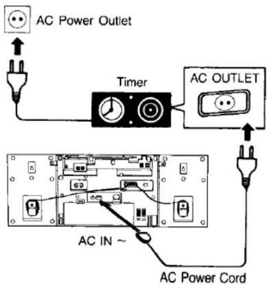
- Connect as shown in the figure below.
- Set the power switch of the timer to "ON".
- Follow the same procedure as described in steps 1–9 of "TAPE PLAYBACK".
- Press the Stop/Eject Button.
- Set the timer to the time that the playback is to start.
- Set the timer switch to "ON". (to switch the power on at the desired time)
- Press the Playback Button. The unit will be turned on and playback will begin at the preset time.
- Refer to the table below for the cassette tape to be used.
| Cassette tape | Time on one side |
| RT-30 (C-30) | 15 minutes |
| RT-60 (C-60) | 30 minutes |
| RT-90 (C-90) | 45 minutes |
■ Timer Recording of Radio Broadcasts (TAPE 1)
- Connect as shown in the figure below.
- Set the power switch of the timer to "ON".
- Follow the procedure described in steps 1-4 of "Recording Radio Broadcasts".
- Set the timer to the time that the recording is to start.
- Set the timer switch to "ON". (to switch the power on at the desired time)
- Press the Record Button. The unit will be turned on, and recording will begin at the preset time.
Note:
Set the timer so that the unit is switched off after the tape has reached the end.
This will insure that the Auto Stop function has released the tape mechanism.
text_image
AC Power Outlet Timer AC OUTLET AC IN ~ AC Power CordMAINTENANCE
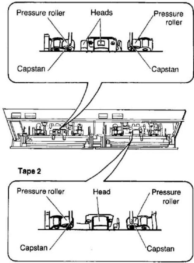
The head assembly, Capstans, and Pressure rollers are in constant contact with the tape. If these parts are dirty, the sound quality will be impaired. Get into the habit of cleaning the parts regularly (after every 10 hours or so of use) in accordance with the procedure outlined below.
- Open the Cassette Compartment covers by pressing the Stop/Eject Buttons.
- Press the TAPE 1 and TAPE 2 Playback Buttons. The Playback Head, Recording/playback head, Erase head, Capstans and the Pressure rollers can be seen of each deck. Clean them with a cotton swab.
Tape 1
text_image
Pressure roller Heads Pressure roller Capstan Capstan Tape 2 Pressure roller Head Pressure roller Capstan CapstanNotes:
- If the heads are extremely dirty, clean then with a soft cloth dampened with a little alcohol.
- Do not bring metal articles or magnetic material, such as a screwdriver, near the head assembly.
- Do not clean the plastic cabinet with benzine or thinner. Clean it with a solution of soap and water.
- Avoid spray-type insecticides. Some insecticides contain chemicals that could cause cabinet deformation.