AZ8560 - Nähmaschine Yamato - Kostenlose Bedienungsanleitung
Finden Sie kostenlos die Bedienungsanleitung des Geräts AZ8560 Yamato als PDF.


Benutzerfragen zu AZ8560 Yamato
0 Frage zu diesem Gerät. Beantworten Sie die, die Sie kennen, oder stellen Sie Ihre eigene.
Eine neue Frage zu diesem Gerät stellen
Laden Sie die Anleitung für Ihr Nähmaschine kostenlos im PDF-Format! Finden Sie Ihr Handbuch AZ8560 - Yamato und nehmen Sie Ihr elektronisches Gerät wieder in die Hand. Auf dieser Seite sind alle Dokumente veröffentlicht, die für die Verwendung Ihres Geräts notwendig sind. AZ8560 von der Marke Yamato.
BEDIENUNGSANLEITUNG AZ8560 Yamato
Instruction Manual (with Parts List)
HIGH SPEED OVERLOCK MACHINE
with Floating Presser Foot
HIGH SPEED SAFETY STITCH MACHINE
with Floating Presser Foot
AZ8060G
AZ8560G
natural_image
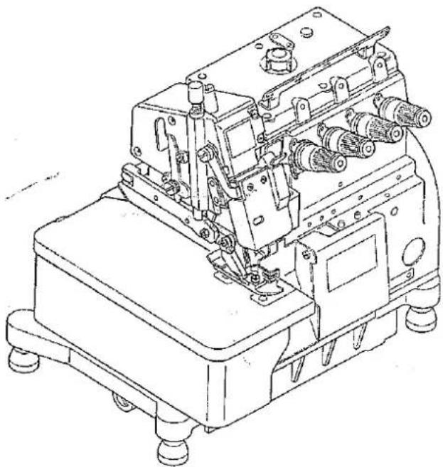
Technical line drawing of a sewing machine (no text or symbols visible)Thank you for purchasing the Model AZ8060G/AZ8560G. This instruction manual provides information on the floating presser foot.
Before using your AZ8060G/AZ8560G, please read the instruction manual together with that for the AZ8000G/AZ8500G and well understand the contents of both documents.
After reading the instruction manual, please store it in a location where it is easily accessible to the operator.
1. Introduction to Model with Floating Presser Foot
1. Features
● The presser foot slides back and forth in conjunction with the vertical and reciprocative movement of the lower feed dog. This mechanism minimizes the twist and deviation of the fabric to be sewn, providing the fabric with a flat, beautiful finish.
● The pressing pressure applied to the fabric to be sewn is decreased, minimizing the bad effect over the fabric.
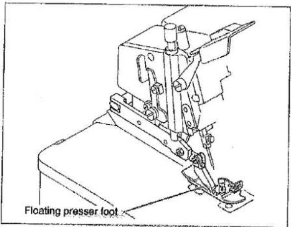
text_image
Floating presser footMovement of floating presser foot
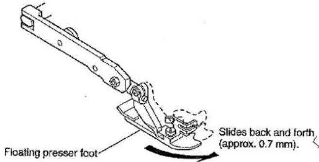
text_image
Floating presser foot Slides back and forth (approx. 0.7 mm).Movement of standard presser foot
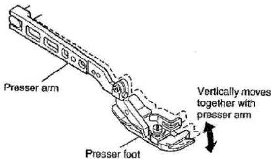
text_image
Presser arm Presser foot Vertically moves together with presser arm2. Differences from AZ8000G/AZ8500G
CAUTION
The maximum sewing speed and presser foot lift are different between the model with floating presser foot (AZ8060G/AZ8560G) and the Model AZ8000G/AZ8500G (see the table given on the right side).
3. Motor Pulley
In order to achieve the maximum performance of the model with floating presser foot, the maximum sewing speed must be lower than that of the AZ8000G/AZ8500G. This will require changing the motor pulley used. Select the best suited motor pulley from the table provided on right side.
CAUTION
Use a motor pulley applicable for the AZ8060G/AZ8560G. Otherwise, the maximum speed will be exceeded and your sewing machine may malfunction.
| Model | AZ8060G class | AZ8560G class |
| Max. sewing speed | 7000 r.p.m | 6500 r.p.m |
| Presser foot rise | 5 mm max. | 5 mm max. |
List of motor pulleys
| Outer dia. of motor pulley (mm) | Sewing machine speed (r.p.m.) | |
| For 50 Hz | For 60 Hz | |
| 90 | 6000 | |
| 95 | 6400 | |
| 100 | 6700 | |
| 110 | 6200 | |
| 115 | 6500 | |
| 120 | 6700 | |
The sewing machine speeds shown in the above table are the values that are obtained when a clutch motor for power supply of 3 phases, 2 polarities, and 400 W is used.
* The outer diameters of commercially available pulleys are in units of 5 mm. Therefore, the above table lists the motor pulleys that have the outer diameters closest to those of the commercially available ones.
2. Assembling the Floating Presser Foot
To replace the presser arm and presser foot, C. set for the AZ8000G/AZ8500G with the floating presser foot, perform the following steps:
1. Components for floating presser foot
Check the parts with the table given on the right side before assembling the floating presser foot.
| Part name | Q'ty |
| Floating presser arm, C. set | 1 |
| Presser foot, C. set | 1 |
| Presser foot release lever stop | 1 |
| Screw | 1 |
2. Assembling the floating presser foot

CAUTION
Before starting these steps, be sure to turn OFF the power and then check that the motor rotation stops.
- Remove the belt from the pulley.
- Manually rotate the pulley for the sewing machine to position the feed dog lower than the upper surface of the stitch plate.
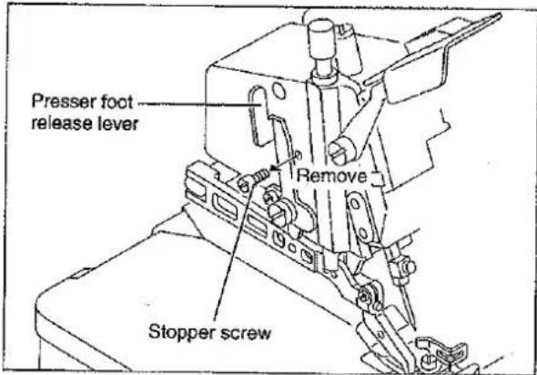
- Remove the stopper screw for the presser foot release lever.
- Tighten the screw for the lever stop as illustrated right.
text_image
Presser foot release lever Remove Stopper screw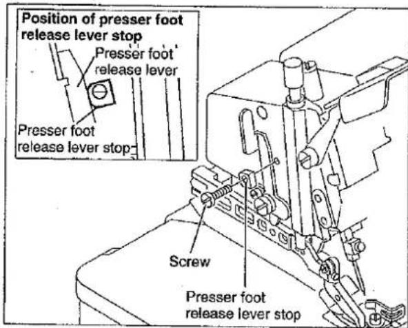
text_image
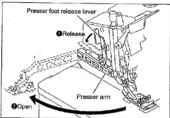
Position of presser foot release lever stop Presser foot release lever Presser foot release lever stop Screw Presser foot release lever stop- Release the lever and open the presser arm.
text_image
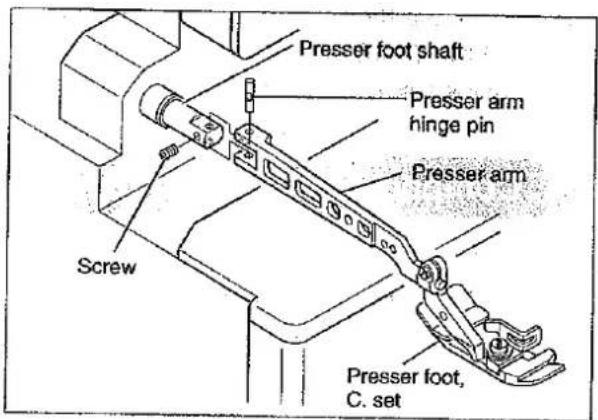
Presser foot release lever ① Release Presser arm ② Open- Remove the presser arm and the presser foot, C. set from the presser foot shaft.
text_image
Presser foot shaft Presser arm hinge pin Presser arm Screw Presser foot, C. set- Connect the floating presser arm, C. set to the presser foot shaft.
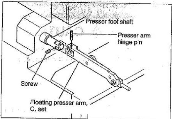
text_image
Presser foot shaft Presser arm hinge pin Screw Floating presser arm, C. set- Adjust the clearance between the top of the lock nut and that of the adjusting screw at 24 mm. (See Page 6 for adjusting this clearance.)
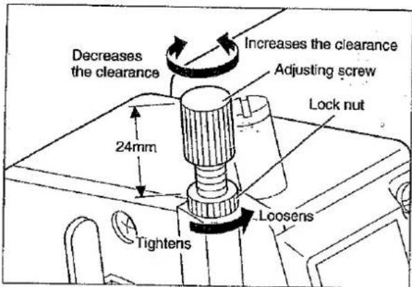
text_image
Decreases the clearance Increases the clearance Adjusting screw Lock nut 24mm Loosens Tightens- Insert the presser foot, C. set to the floating presser arm, C. set.

text_image
Floating presser arm, C. set Insert Presser foot, C. set- Install the floating presser arm back in place.
- Align the needle drop of the presser foot, C. set with that of the stitch plate, and then tighten the lock screw for the presser foot, C. set.

CAUTION
In aligning the needle drop of the presser foot, C. set with that of the stitch plate, adjust the bottom of the presser foot to be in parallel with the stitch plate.
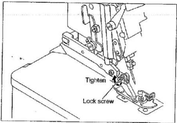
text_image
Tighten Lock screw3. Adjustment after Installation
- Check that the feed dog is positioned lower than the upper surface of the stitch plate.
- Check that the lever makes contact with the presser foot pin.
- Check that the needle drop of the presser foot, C. set aligns with that of the stitch plate. (front/rear, right/left and parallel position)
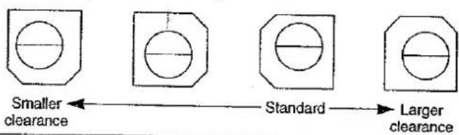
- Check that the clearance between the top of the groove on the presser arm stop and that of the floating presser arm, C. set stop is between 0.5 and 1 mm. To adjust the clearance, change the position of the lever stop.
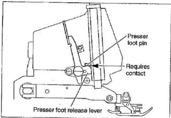
text_image
Presser foot pin Requires contact Presser foot release leverLever stopper positions and clearance changes (the clearance increases in the order of left to right)
text_image
Smaller clearance Standard Larger clearance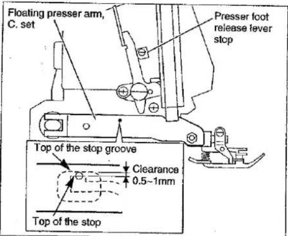
text_image
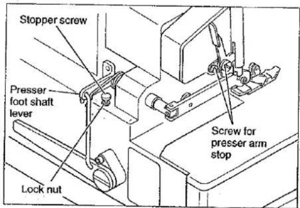
Floating presser arm, C. set Presser foot release lever stop Top of the stop groove Clearance 0.5~1mm Top of the stop- Loosen the lock nut for the stopper screw on the presser foot shaft lever, and the screw for the presser arm stop.
text_image
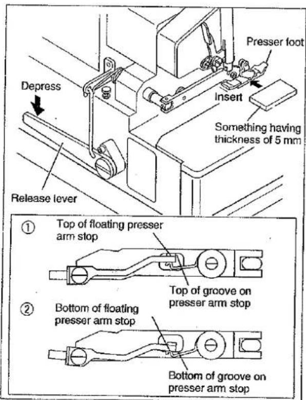
Stopper screw Presser foot shaft lever Lock nut Screw for presser arm stop- Depress the presser release lever, and then insert something of 5 mm in thickness between the top of the stitch plate and the bottom of the presser foot, such that they are in parallel with one another.
①When the release lever is depressed, the floating presser arm, C. set will be positioned as illustrated.
②When something of 5 mm in thickness is inserted between the top of the stitch plate and the bottom of the presser foot, the floating presser arm, C. set will be positioned as illustrated.
text_image
Depress Release lever Presser foot Insert Something having thickness of 5 mm ① Top of floating presser arm stop Top of groove on presser arm stop ② Bottom of floating presser arm stop Bottom of groove on presser arm stop- Let the stopper screw make contact with the shaft lever when the presser arm and floating presser arm are positioned as illustrated in ②, and then tighten the lock nut.
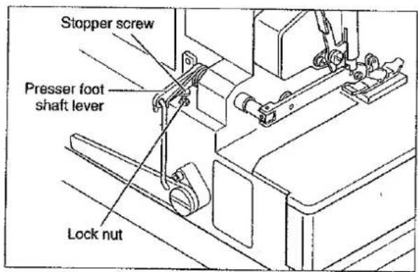
text_image
Stopper screw Presser foot shaft lever Lock nut- Let the presser arm stop make contact with the presser arm, and then tighten the screw.
- Remove the thing that has been inserted between the top of the stitch plate and the bottom of the presser foot.
- Manually rotate the pulley for the sewing machine, and check that the presser rod does not move vertically. If the presser rod moves, tighten the adjusting screw until the presser rod no longer moves vertically. (For the adjusting procedure, see P. 6.)
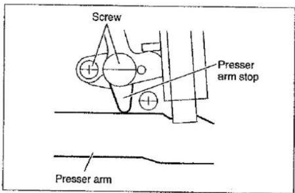
text_image
Screw Presser arm stop Presser arm- Stretch the belt between the sewing machine and motor pulley.
- Activate the sewing machine and check that the presser foot functions properly. If the presser foot does not function properly, adjust the presser foot adjusting spring. (For the adjusting procedure, see P. 6.)
- Check that the presser arm remains stationary when the leading edge of the presser foot is lifted with a finger.
3. Troubleshooting
1. Troubleshooting

CAUTION
Before starting these steps, be sure to turn OFF the motor and then check that the motor rotation stops.
| Trouble | Corrective action |
| ● Idling noises are too loud. | Adjust the position of the adjusting screw for the presser foot by 90°.(See “3. Adjustment the presser foot adjusting spring”) |
| ● The fabric is not fed straight. | Perform the steps 10 to 13 under “Adjustment after Installation.” |
| ● The fabric is not fed properly. | Perform the steps 10 to 13 under “Adjustment after Installation.” |
| ● The fabric deviates greatly. | Perform the steps 10 to 13 under “Adjustment after Installation.” |
| ● The fabric is often flawed during feed. | Perform the steps 10 to 13 under “Adjustment after Installation.” |
2. Adjusting the presser foot spring
Loosen the lock nut and then adjust the presser foot spring by turning the adjusting screw. To check the adjusted state or measure any dimension, tighten the lock nut in advance.
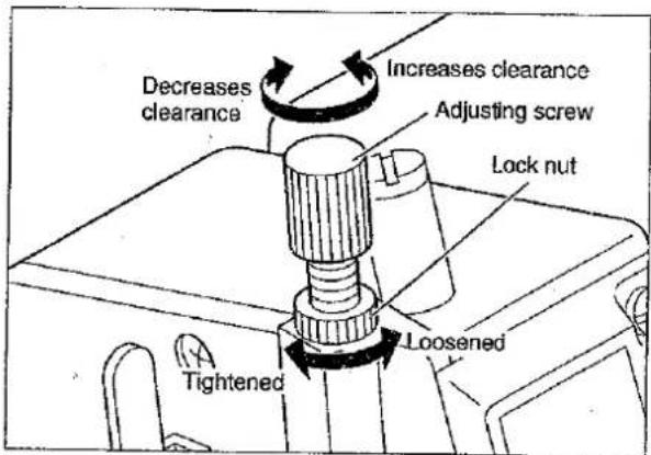
text_image
Decreases clearance Increases clearance Adjusting screw Lock nut Loosened Tightened3. Adjusting the presser foot adjusting spring
Adjust the position of the presser foot spring in a range between 60° and 90°. (The presser foot spring was adjusted in the position of 60° at factory.)
- Depress the presser foot release lever and open the presser arm.
- Loosen the lock screw for the presser foot adjusting spring using a slotted screwdriver, adjust the position of the adjusting spring, and then tighten the lock screw.
- After finishing the adjustment, install the presser arm back in place and check that it remains stationary when the leading edge of the presser foot is lifted with a finger.
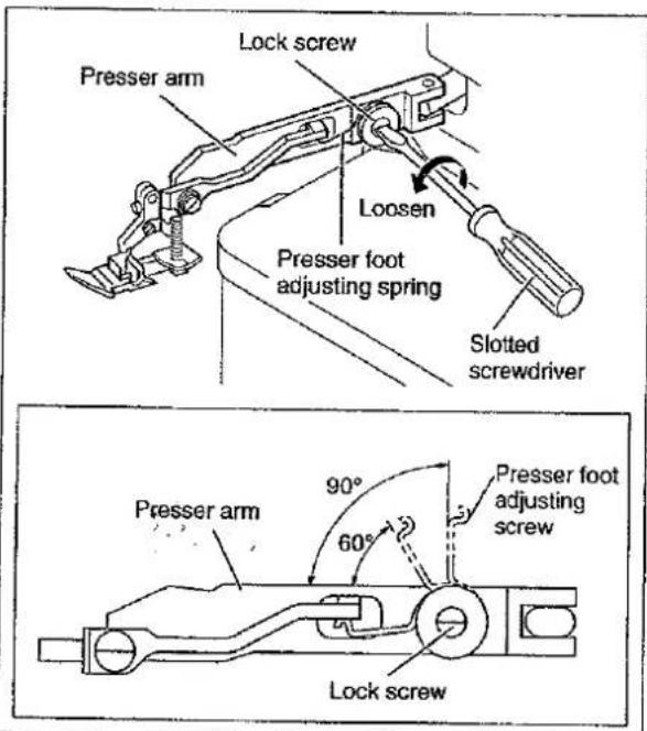
text_image
Lock screw Presser arm Loosen Presser foot adjusting spring Slotted screwdriver 90° 60° Presser foot adjusting screw Presser arm Lock screw4. Parts List
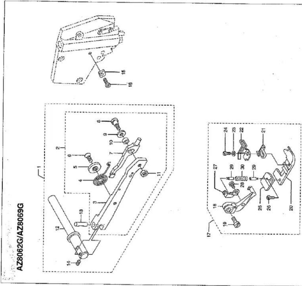
AZ8062G/AZ8069G
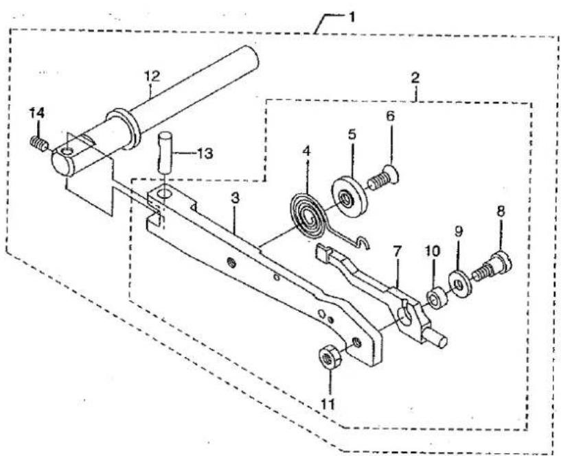
text_image
Technical diagram of a mechanical assembly with numbered components for identification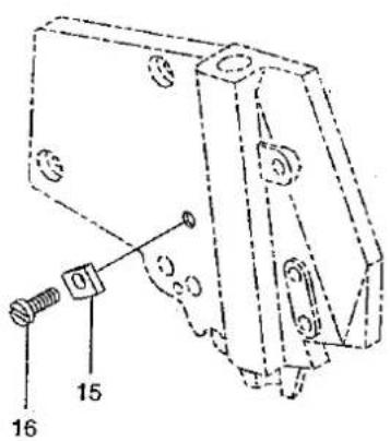
text_image
Technical diagram of a mechanical assembly with numbered components and mounting holes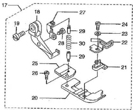
text_image
Exploded view diagram of a mechanical assembly with numbered parts for identification■AZ8062G・AZ8069G EXCLUSIVE PARTS サブモデル専用部品
| Ref.No. | Parts NO. | Description | 品名 | Amt. Req. |
| 1 | 2150220 | Presser Arm, C. Set | 押工腕(組) | 1 |
| 2 | 2150223 | Floating Presser Arm, C. Set | フローティングアーム(組) | 1 |
| 3 | 2150221 | Presser Arm | 押工腕 | 1 |
| 4 | 2100750 | Adjusting Spring | 調節バネ | 1 |
| 5 | 2100751 | Locking Disc | 回り止メ | 1 |
| 6 | 130010 | Screw (M4 -0.7×8.3) | 止ネジ | 1 |
| 7 | 2150222 | Floating Presser Arm | フローティングアーム | 1 |
| 8 | 170039 | Screw (M4 -0.7×12) | 止ネジ | 1 |
| 9 | 300000 | Washer | ワッシャ | 1 |
| 10 | 2100752 | Bushing | ブッシュ | 1 |
| 11 | 100001 | Nut | ナット | 1 |
| 12 | 2100189 | Presser Foot Shaft | 押工軸 | 1 |
| 13 | 2100199 | Presser Arm Hinge Pin | 押工腕ヒンジピン | 1 |
| 14 | 160001 | Screw (M4 -0.7×4) | 止ネジ | 1 |
| 15 | 2100755 | Presser Foot Release Lever Stop | 手揚ゲストッパ | 1 |
| 16 | 110068 | Screw (M4 -0.7×8) | 止ネジ | 1 |
| 17 | 下麦参照 | Presser Foot, C. Set | 押工(組) | 1 |
| 18 | 2157004 | Presser Foot Hinge | 押エヒンジ | 1 |
| 19 | 110004 | Screw (M3.5 -0.6×8) | 止ネジ | 1 |
| 20 | 2157020 | Presser Foot (Lower) | 押工(下) | 1 |
| 21 | 2157205 | Presser Foot Stitch Tongue (Y5) | 爪 | 1 |
| 22 | 2157030 | Finger Guard | フィンガガード | 1 |
| 23 | 000444 | Washer | ワッシャ | 1 |
| 24 | 005036 | Screw (1/8 -44×5.6) | 止ネジ | 1 |
| 25 | 2157035 | Thread Chain Guide | 空環ガイド | 1 |
| 26 | 001230 | Screw (3/32 -56×3.8) | 止ネジ | 1 |
| 27 | 2157036 | Presser Foot Spring Setting Piece | 押エバネ取付片 | 1 |
| 28 | 110054 | Screw (M3 -0.5×3.5) | 止ネジ | 1 |
| 29 | 280008 | Screw (3/32 -56×1.8) | 止ネジ | 2 |
| 30 | 22261 | Presser Foot Spring | 押エバネ | 1 |
| Model Name | Floating Presser Foot, C.Set | Parts included in Floating Presser Foot, C. Set | Ref. No. 17 Presser Foot, C. Set | Stitch Plate | Differential Feed Dog | Main Feed Dog | Partial Feed Dog | Needle Clamp | Upper Looper |
| AZ8062G-Y5 | 2159915 | Ref. No.2 · 15 · 16 · 17 | 2157147 | 2108004 | 2109005 | 2109006 | 2109067 | 2159102 | 2109322 |
| AZ8069G-Y5 | * | * | * | 2108106 | 2109038 | * | 2109052 | * | * |
AZ8560G
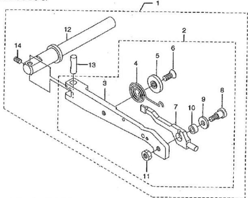
text_image
Technical diagram of a mechanical assembly with numbered components for identification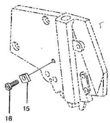
text_image
Technical diagram of a mechanical assembly with numbered components labeled 15 and 16AZ8560G-A4
text_image
Technical diagram of mechanical components with numbered parts for identification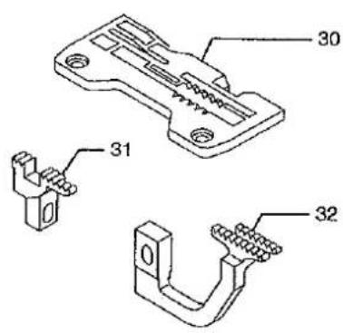
text_image
Technical diagram of a mechanical component with labeled parts 30, 31, and 32AZ8560G-C5
text_image
Technical diagram of a mechanical assembly with numbered parts for identification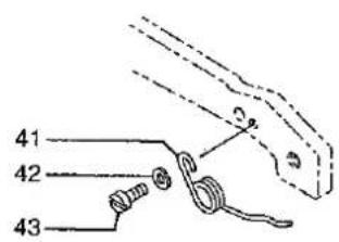
text_image
41 42 43■AZ8560G EXCLUSIVE PARTS
サブモデル専用部品
| Ref.No. | Parts NO. | Description | 品名 | Amt. Req. |
| 1 | 2150190 | Presser Arm, C. Set | 押工腕(組) | 1 |
| 2 | 2150193 | Floating Presser Arm, C. Set | フローティングアーム(組) | 1 |
| 3 | 2150191 | Presser Arm | 押工腕 | 1 |
| 4 | 2100750 | Adjusting Spring | 調節パネ | 1 |
| 5 | 2100751 | Locking Disc | 回り止メ | 1 |
| 6 | 130010 | Screw (M4 - 0.7×8.3) | 止ネジ | 1 |
| 7 | 2150192 | Floating Presser Arm | フローティングアーム | 1 |
| 8 | 170039 | Screw (M4 - 0.7×12) | 止ネジ | 1 |
| 9 | 300000 | Washer | ワッシャ | 1 |
| 10 | 2100752 | Bushing | ブッシュ | 1 |
| 11 | 100001 | Nut | ナット | 1 |
| 12 | 2100189 | Presser Foot Shaft | 押工軸 | 1 |
| 13 | 2100199 | Presser Arm Hinge Pin | 押工腕ヒンジピン | 1 |
| 14 | 160001 | Screw (M4 - 0.7×4) | 止ネジ | 1 |
| 15 | 2100755 | Presser Foot Release Lever Stop | 手揚ゲストッパ | 1 |
| 16 | 110068 | Screw (M4 - 0.7×8) | 止ネジ | 1 |
| 17 | 下表参照 | Presser Foot, C. Set | 押工(組) | 1 |
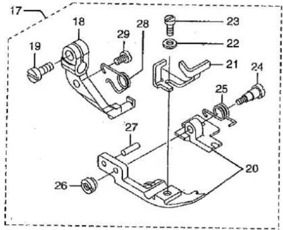
| 18 | 2157355 | Presser Foot Hinge | 押エヒンジ | 1 |
| 19 | 110004 | Screw (M3.5 - 0.6×8) | 止ネジ | 1 |
| 20 | 2107692 | Presser Foot (Front/Rear) Unit (A4) | 押工(前・後)(組) | 1 |
| 21 | 2107642 | Presser Foot Hinge Spring | 押エヒンジパネ | 1 |
| 22 | 000444 | Washer | ワッシャ | 1 |
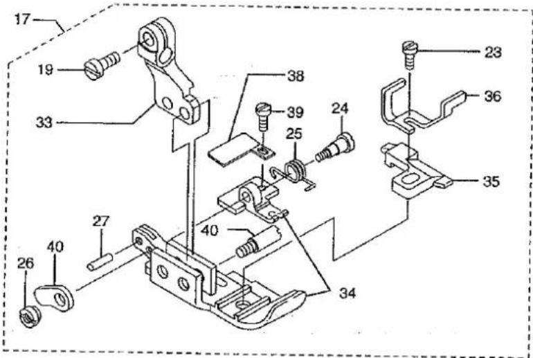
| 23 | 005036 | Screw (1/8 - 44×5.6) | 止ネジ | 1 |
| 24 | 006093 | Screw (3/32 - 56×5.6) | 止ネジ | 1 |
| 25 | 0025035 | Presser Foot Spring (Small) | 押エパネ(小) | 1 |
| 26 | 000216 | Nut | ナット | 1 |
| 27 | 000747 | Pin | ピン | 1 |
| 28 | 2157306 | Presser Foot Spring (Large) | 押エパネ(大) | 1 |
| 29 | 110085 | Screw (M3 - 0.5×4.5) | 止ネジ | 1 |
| 30 | 2108135 | Stitch Plate (A4) | 針板 | 1 |
| 31 | 2106015 | Main Feed Dog (A4) | 後送り | 1 |
| 32 | 2106014 | Differential Feed Dog (A4) | 前送り | 1 |
| 33 | 2157356 | Presser Foot Hinge | 押エヒンジ | 1 |
| 34 | 2107412 | Presser Foot (Front/Rear) Unit (C5) | 押工(前・後)(組) | 1 |
| 35 | 2107105 | Presser Foot Stitch Tongue (C5) | 爪 | 1 |
| 36 | 2107163 | Presser Foot Adjusting Plate | 押工調節板 | 1 |
| 37 | 004136 | Screw (1/8 - 44×2.7) | 止ネジ | 1 |
| 38 | 0020501 | Thread Chain Guide (C) | 空環ガイド | 1 |
| 39 | 004141 | Screw (3/32 - 56×2.1) | 止ネジ | 1 |
| 40 | 0033529 | Presser Foot (Rear)Adjusting Plate | 押工調節片 | 1 |
| 41 | 2107699 | Presser Foot Spring (Large) | 押エパネ(大) | 1 |
| 43 | 004404 | Screw (3/32 - 56×5.1) | 止ネジ | 1 |
| 42 | 000531 | Washer | ワッシャ | 1 |
| Model Name | Floating Presser Foot, C.Set | Parts included in Floating Presser Foot, C. Set | Ref. No. 17 Presser Foot, C. Set | Stitch Plate | Differential Feed Dog | Main Feed Dog | Partial Feed Dog | Needle Clamp | Upper Looper |
| AZ8560G-A4 | 2159920 | Ref. No. 2-15-16-17-30-31-32 | 2157365 | (2108135) | (2106014) | (2106015) | 2109052 | 2159111 | 2109320 |
| AZ8560G-C5 | 2159921 | Ref. No. 2-15-16-17-41-42-43 | 2157366 | 2108076 | 2109055 | 2109056 | 2159112 |
4. Parts List
■AZ8062G・AZ8069G EXCLUSIVE PARTS サブモデル専用部品
| Ref.No. | Parts NO. | Description | 品名 | Amt. Req. |
| 1 | 2150220 | Presser Arm, C. Set | 押工線(組) | 1 |
| 2 | 2150223 | Floating Presser Arm, C. Set | フローティングアーム(組) | 1 |
| 3 | 2150221 | Presser Arm | 押工図 | 1 |
| 4 | 2100750 | Adjusting Spring | 膜節パネ | 1 |
| 5 | 2100751 | Locking Disc | 図り止メ | 1 |
| 6 | 130010 | Screw (M4-0.7×8.9) | 止ネジ | 1 |
| 7 | 2150222 | Floating Presser Arm | フローティングアーム | 1 |
| 8 | 170039 | Screw (M4-0.7×12) | 止ネジ | 1 |
| 9 | 300000 | Washer | ワッシャ | 1 |
| 10 | 2100752 | Bushing | ブッシュ | 1 |
| 11 | 100001 | Nut | ナット | 1 |
| 12 | 2100189 | Presser Foot Shaft | 押工軸 | 1 |
| 13 | 2100199 | Presser Arm Hinge Pin | 押工顔ヒンジピン | 1 |
| 14 | 160001 | Screw (M4-0.7×4) | 止ネジ | 1 |
| 15 | 2100755 | Presser Foot Release Levar Stop | 手撮ゲストッパ | 1 |
| 16 | 110068 | Screw (M4-0.7×8) | 止ネジ | 1 |
| 17 | 下衣参照 | Presser Foot, C. Set | 押工(組) | 1 |
| 18 | 2157004 | Presser Foot Hinge | 押エヒンジ | 1 |
| 19 | 110004 | Screw (M3.5-0.6×8) | 止ネジ | 1 |
| 20 | 2157020 | Presser Foot (Lower) | 押工(下) | 1 |
| 21 | 2157205 | Presser Foot Stitch Tongue (Y5) | 爪 | 1 |
| 22 | 2157030 | Finger Guard | フィンガガード | 1 |
| 23 | 000444 | Washer | ワッシャ | 1 |
| 24 | 005096 | Screw (1/8-44×5.6) | 止ネジ | 1 |
| 25 | 2157035 | Thread Chain Guide | 空腹ガイド | 1 |
| 26 | 001230 | Screw (3/32-56×3.6) | 止ネジ | 1 |
| 27 | 2157036 | Presser Foot Spring Setting Piece | 押エバネ取付片 | 1 |
| 26 | 110054 | Screw (M3-0.5×3.5) | 止ネジ | 1 |
| 29 | 280008 | Screw (3/32-56×1.6) | 止ネジ | 2 |
| 30 | 22261 | Presser Foot Spring | 押エバネ | 1 |
| Model Name | Floating Pressor Foot, C.Sut | Parts included in Floating Pressor Foot, C. Set | Ref. No. 17 Pressor Foot, C. Set | Stitch Plate | Differential Feed Dog | Main Feed Dog | Partial Feed Dog | Needle Clamp | Upper Looper |
| AZ8069G-Y5 | 2159915 | Ref. No.2 · 15 · 16 · 17 | 2157147 | 2108004 | 2100005 | 2109006 | 2109067 | 2159102 | 2109322 |
| AZ8069G-Y5 | * | * | * | 2108106 | 2109038 | * | 2109052 | * | * |
[Unreadable]