VF2400-8 - Nähmaschine Yamato - Kostenlose Bedienungsanleitung
Finden Sie kostenlos die Bedienungsanleitung des Geräts VF2400-8 Yamato als PDF.


Benutzerfragen zu VF2400-8 Yamato
0 Frage zu diesem Gerät. Beantworten Sie die, die Sie kennen, oder stellen Sie Ihre eigene.
Eine neue Frage zu diesem Gerät stellen
Laden Sie die Anleitung für Ihr Nähmaschine kostenlos im PDF-Format! Finden Sie Ihr Handbuch VF2400-8 - Yamato und nehmen Sie Ihr elektronisches Gerät wieder in die Hand. Auf dieser Seite sind alle Dokumente veröffentlicht, die für die Verwendung Ihres Geräts notwendig sind. VF2400-8 von der Marke Yamato.
BEDIENUNGSANLEITUNG VF2400-8 Yamato
1jamato®
取 扱 說 明 書
Instruction Manual
Parts List
超高速平2・3本針ミシン
SUPER HIGH SPEED FLAT BED
CHAINSTITCH MACHINE
VF2400-8
VF2400の取扱説明書と調整が異なる部分を記載しています。
本製品のご使用にあたっては、本書とVF2400の取扱説明書を併せて最後までお読みいただき、内容をよく理解してから正しくお使いください。
また、お読みになった後は、お使いになる方がいつでも見られるところに保管してください。
This instruction manual includes adjustments differed from VF2400.
Before using your VF2400-8, please read both of the instruction manuals and understand the contents well.
After reading the instruction manuals, please keep them in a location where it is easily accessible to the operator.
目 次/CONTENTS
1. 縫速度

2. 正しい使い方 2
糸の通し方 2
3. ミシンの調整 3
3.1 針糸調子 3
3.2 上飾り糸調子 5
4. 仕様 6
1. Sewing speed 7

2. Proper operation 8
Threading 8
3. Adjustments 9
3.1 Needle thread tension 9
3.2 Top cover thread tension 11
4. Specifications 11
\*\*\*ILLUSTRATED SPARE PARTS LIST \*\*\*
お願い
◇本書は主に技術者向けに作成されていますが、このマークが付いている項目は、ミシンを大切にお使いいただくために、オペレータの方にも読んでいただきたい項目です。
◇本書の説明図の左下に記載されている数字は図ナンバーです。必要に応じて、本文中に図ナンバーを記載していますので、該当する説明図と合わせてご覧ください。
Attention
This instruction manual is designed mainly for technicians, but it is advisable that also operators read the instructions with mark to use the machine properly.
◇The numbers in lower left corners of figures are figure numbers. We use them in texts as needed for your reference.
おことわり
本製品は改良などにより、使用部品を変更することがあります。その際には、本書の内容および説明図などの一部が、本製品と一致しない場合がありますので、あらかじめご了承ください。また、本書の作成にあたっては万全を期しておりますが、万一の誤りや記載もれなどが発見されても直ちに修正できないことがあります。
Attention
The description in this instruction manual is subject to change for improvements of the commodity without notice.
1. 縫速度
このミシンの最高縫速度は5500rpm、常用縫速度は5000rpmです。
新しいミシンを使用するときは、最初の200時間(約1カ月)は4400rpm程度で使用すると、ミシンを良好な状態で長期間使用することができます。
2. 正しい使い方
糸の通し方

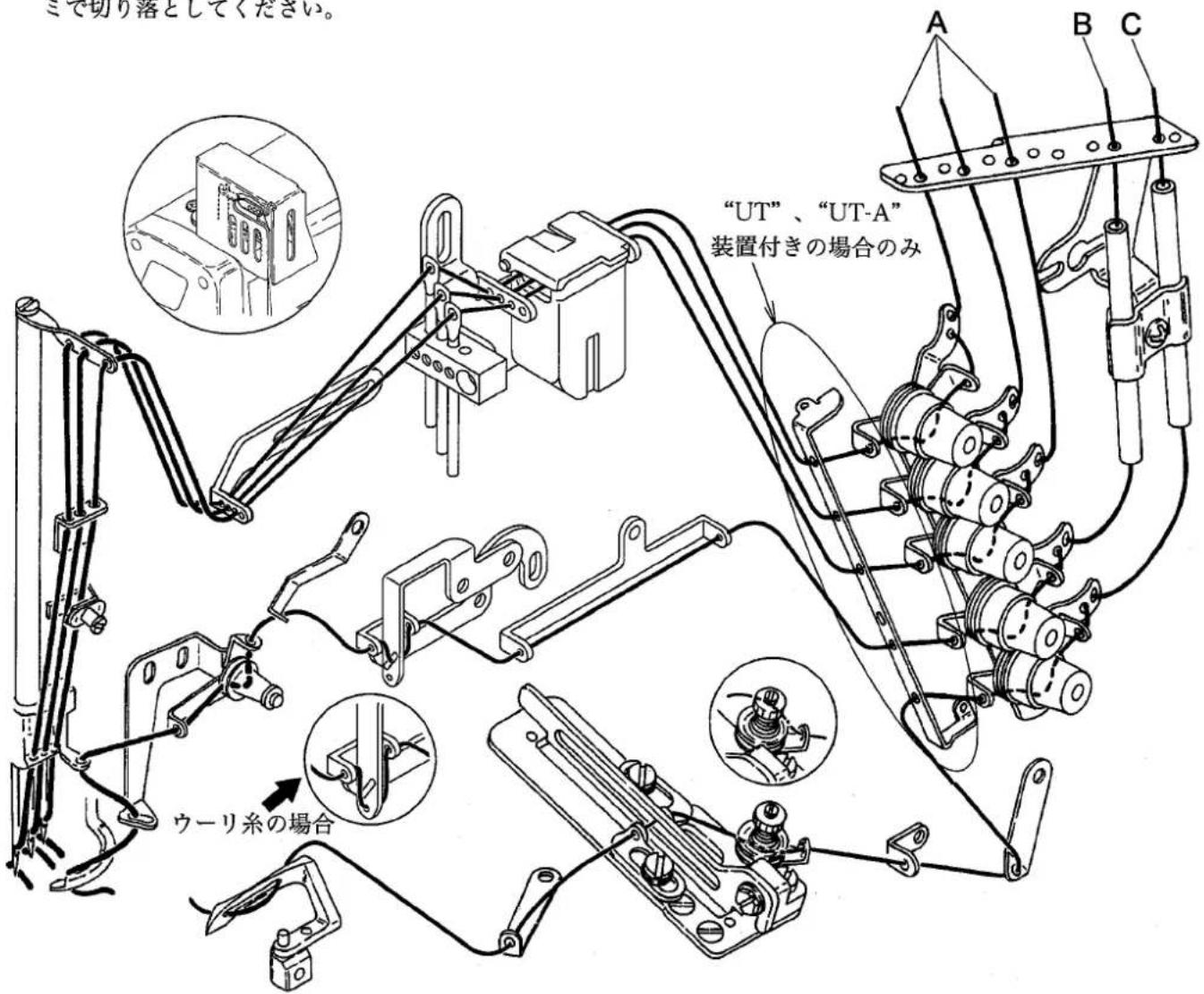
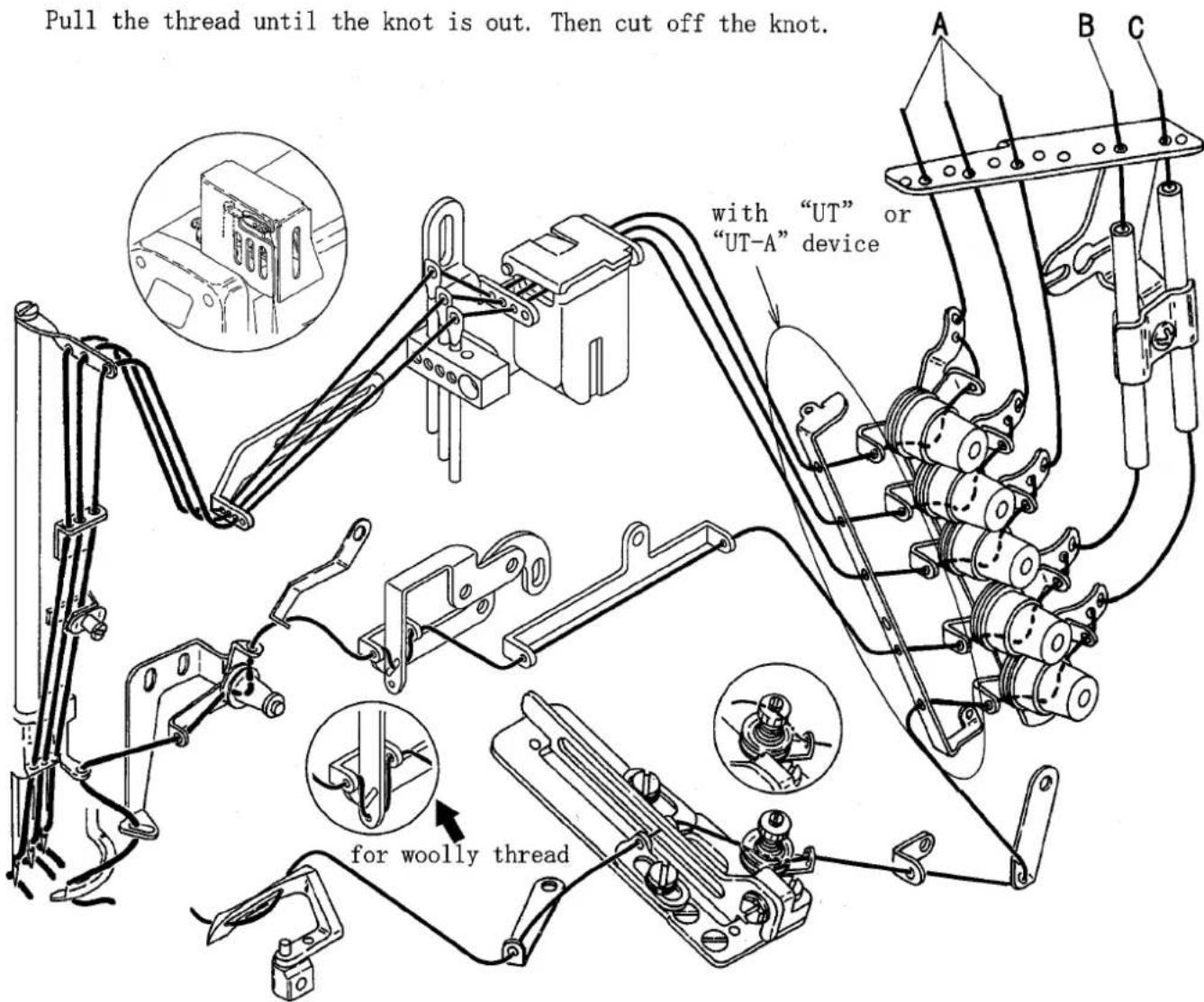
糸が通っていない場合は、この糸通し図を見て正しく通してください。
糸が通してある場合は、縫製用の糸を結んでください。
A 針糸
糸の結び目を針の手前まで引き出し、いったん結び目を切り落としてから改めて針に通し直してください。左針の針糸が必ず一番奥になるように図を見て正しく通してください。
B 上飾り糸
結び目が出てくるまで糸を引き出してください。
C ルーパ糸
結び目が出てくるまで糸を引き出してから、先端をハサミで切り落としてください。
text_image
ミで切り落としてください。 "UT"、"UT-A" 装置付きの場合のみ A B C ウーリ糸の場合图1
3. ミシンの調整
注意
作業を行う前に、必ずモータの電源を切り、モータの回転停止を確認してください。
3.1 針糸調子
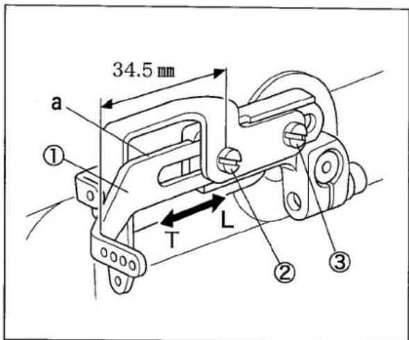
針糸繰リ
調節方法:
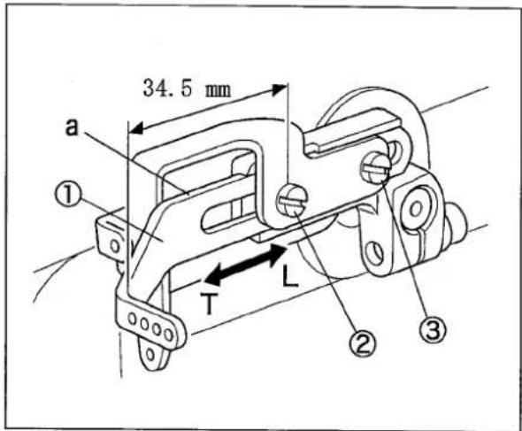
(1) 止ネジ②③を緩める。
● 針糸繰り①をT方向に動かすと、針糸が締まります。
● 針糸繰り①をL方向に動かすと、針糸が緩みます。
(2) 止ネジ②③を締め付ける。
針棒が最上点にあるとき、針糸繰り①のa部が水平の状態で止ネジ②から先端まで34.5 mmになるのが標準です。
text_image
34.5 mm a ① T L ② ③图2
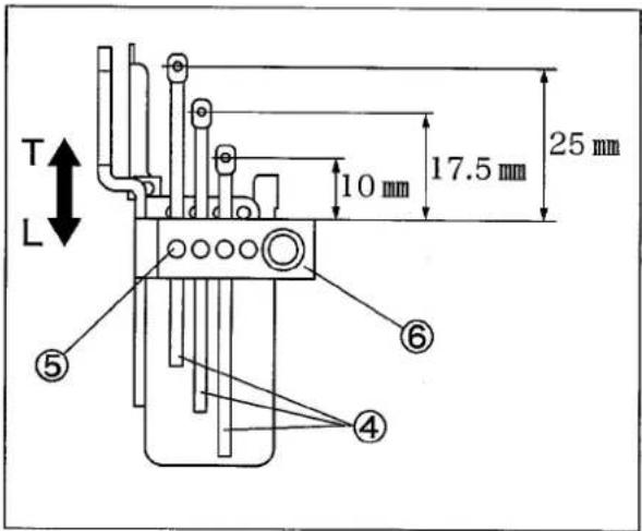
針糸道
上記の調節で不十分な場合、又は各針糸ごとに調節する場合は、針糸道を調節します。
調節方法:
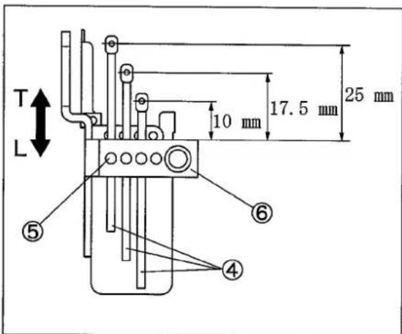
(1) 止ネジ⑤を緩める。
- 針糸道④をT方向に動かすと、針糸が締まります。
- 針糸道④を L 方向に動かすと、針糸が緩みます。
(2) 止ネジ⑤を締め付ける。
針糸道台⑥から各針糸道④の糸穴までの距離が下記のようになるのが標準です。
左針…25 mm
中針…17.5 mm
右針…10mm
text_image
T L 10 mm 17.5 mm 25 mm ⑤ ⑥ ④图3
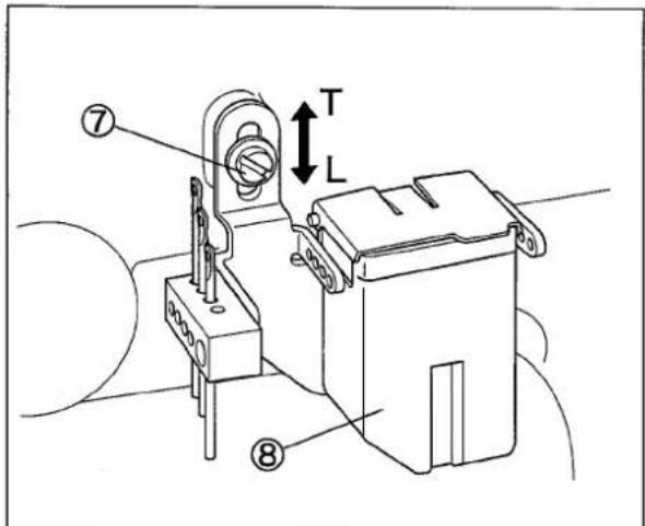
針糸道全体を調節する方法:
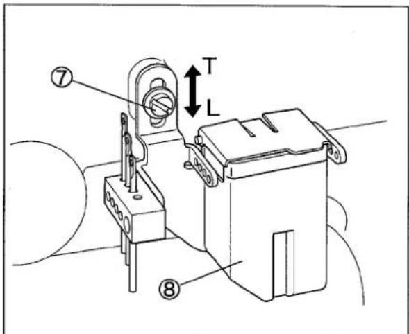
(1) 止ネジ⑦を緩める。
- SP 装置⑧を T 方向に動かすと、針糸が締まります。
- SP 装置⑧を L 方向に動かすと、針糸が緩みます。
(2) 止ネジ⑦を締め付ける。
SP 装置を最も上げた位置が標準です。
text_image
⑦ T L ⑧图4
注意
作業を行う前に、必ずモータの電源を切り、モータの回転停止を確認してください。
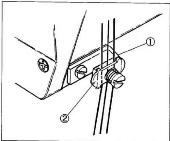
糸の種類によって針糸のループができにくいものがあり、ルーパが針糸をすくうことができず、目飛びの原因になることがあります。
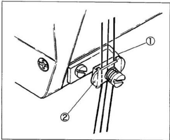
この場合は、図に示すように小調子台(組)(#3103000)①を使用して、針糸を小調子皿②に通してください。
(注) UT装置付きの場合は、縫い始めに縫い目を構成しなくなりますので、使用しないでください。
text_image
Technical diagram showing mechanical assembly with labeled parts ① and ②图5
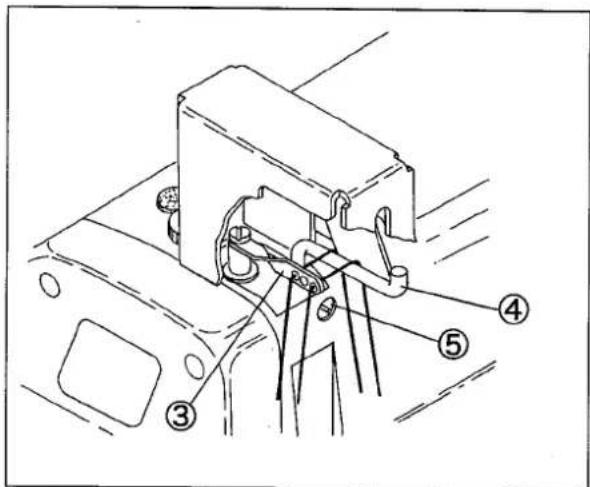
合織糸などの伸びのある糸を使用し、針糸のループの形成が不安定な場合に針糸受ケを使用してください。
針棒が最下点のとき、針棒糸道③の糸穴の中心と針糸受ケ④の上面とが同じ高さで、かつ針棒糸道③と針糸受ケ④とが平行になるのが標準です。
針糸受ケ④の高さと左右の位置は止ネジ⑤を緩めて調節してください。
text_image
Technical diagram of an electrical component with numbered parts labeled ③, ④, and ⑤图6
3.2 上飾り糸調子
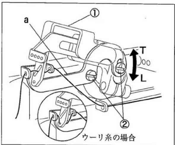
調節は、止ネジ②を緩めて飾り糸道(左)①を動かして行います。
● T方向に回すと、糸の繰り量が少なくなります。
● L方向に回すと、糸の繰り量が多くなります。
飾り糸道(左)①の a 部が水平になるのが標準位置です。
飾り糸に伸びのあるウーリ糸等を使用するときは、飾り糸道(左)①をL方向に回してください。
(注) ウーリ糸の場合は下側の糸穴に通してください。
text_image
a ① T L ② ウーリ系の場合图7
| 型式 | VF2400-8, VF2500-8 | VF2403-8, VF2503-8 |
| 名称 | 高速平ベッド型2・3本針偏平縫いミシン | |
| 外観寸法 | 500mm(長)×250mm(幅)×430mm(高) | |
| 重量 | 41kg | |
| 縫目型式 | ISO規格406, 407, 602, 605 | |
| 用途 | ニット、メリヤス等の地縫い、合わせ縫い、裾引き縫い他 | テープ付 |
| 縫速度 | 最高每分5500rpm(間欠運転時) | |
| 縫い目長さ | 1.4~3.6mm縫い目数1吋(25.4mm)間7~18針30mm間8~21針 | |
| 使用針 | シュメッツ又はオルガン製のUY×128GAS#65~#90 | |
| 針幅 | 3本針4.8mm, 5.6mm, 6.0mm, 6.4mm2本針3.2mm, 4.0mm, 4.8mm, 6.4mm | |
| 針のストローク | 31mm | |
| 押エ上り量 | 上飾り付き:7.0mm、上飾り無し:8.0mm 6.0(針幅5.6mm)から8mm(針幅3.2mm) | 上飾り無し:7.0mm 5.0(針幅6.4mm)から7.0mm(針幅3.2mm) |
| 送り調節方法 | プッシュボタン方式 | |
| 差動送り比率 | 最大正差動1:2, 最大逆差動1:0.7 | |
| 差動送り調節方法 | 外部からレバーを上下することにより回転中も調節可 | |
| 潤滑方法 | ポンプによる自動給油 | |
| 潤滑油 | ヤマトSFオイルNo.28 | |
| 貯油量 | 1100cc | |
| 据付け方法 | 全沈式、又は半沈式 | |
1. Sewing speed
The highest sewing speed of this sewing machine is 5500rpm, and the sewing of using regularly speed is 5000rpm.
When a new sewing machine is used, the first 200 hours (about one month) can excellently use the sewing machine for a long term by using it by about 4400 rpm.
2. Proper operation
Threading

When not threaded, thread correctly as shown in Fig. 1.
When threaded, rethread after knotting preset threads.
A: Needle thread
Pull out the thread until it is in front of the needle. Then cut off the knot before needle eye to rethread.
Thread correctly for the left needle in the inmost position as shown in Fig. 1.
B: Top cover thread
Pull the thread until the knot is out.
C: Looper thread
Pull the thread until the knot is out. Then cut off the knot.
text_image
Pull the thread until the knot is out. Then cut off the knot. with "UT" or "UT-A" device for woolly threadFig. 1
3. Adjustments

WARNING
Before adjusting, ALWAYS turn the motor switch OFF and check that the motor has already stopped.
3.1 Needle thread tension
Needle thread take-up:
Adjusting:
(1) Loosen the screws② and ③.
● To tighten the needle thread, move the needle thread take-up① in the direction "T".
● To loosen the needle thread, move the needle thread take-up① in the direction "L".
(2) Tighten the screws② and ③ securely.
As standard, set the needle bar at the highest point. Make a distance from the screw② to the needle thread take-up① tip to 34.5 mm when the part "a" is horizontally.
Needle thread eyelet:
If not enough for adjusting above or when adjusting each eyelet, adjust them as follows.
Adjusting:
(1) Loosen the screws⑤.
● To tighten the needle thread, move each eyelet④ in the direction "T".
● To loosen the needle thread, move each eleyet ④ in the direction “L”.
(2) Tighten the screws⑤ securely.
As standard, make a distance from the needle thread eyelet holder ⑥ to each eye of the needle thread eyelet ④ as below.
Left needle: 25 mm
Middle needle: 17.5 mm
Right needle: 10 mm
Adjusting all eyelets together:
(1) Loosen the screw⑦.
● To tighten the needle thread, move the SP device⑧ in the direction "T".
● To loosen the needle thread, move the SP device⑧ in the direction “L”.
(2) Tighten the screw⑦ securely.
As standard, set the SP device at the highest point.
text_image
34.5 mm a ① T L ② ③Fig. 2
text_image
T L 10 mm 17.5 mm 25 mm ⑤ ⑥ ④Fig. 3
text_image
⑦ T L ⑧Fig. 4

WARNING
Before adjusting, ALWAYS turn the motor switch OFF and check that the motor has already stopped.
As a needle thread is difficult to form a loop depening on a type of thread, the looper cannot catch a needle thread. It can cause skip stitch. Then thread the needle thread through the needle thread retainer dice② with the needle thread retainer support①(No. 3103000).
Note: When using a UT device, do not use the needle thread retainer support ① because a seam cannot be formed at the beginning of sewing.
text_image
Technical diagram showing mechanical assembly with labeled parts ① and ②Fig. 5
Use the needle thread guide when a loop cannot be formed by a needle thread unstably with stretchable thread like as synthetic thread.
As standard, align the center of the eye of the needle bar thread eyelet ③ even with the top of the needle thread guide ④, and they are parallel when the needle bar is at the lowest point.
Loosen the screw⑤ to adjust the height and right-and-left position of the needle thread guide④.
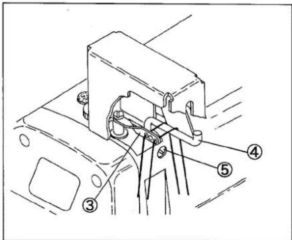
text_image
Technical diagram of a mechanical assembly with numbered components labeled ③, ④, and ⑤Fig. 6
3.2 Top cover thread tension
Loosen the screws② and move the top cover thread eyelet(left)① to adjust it.
● To decrease take-up amount, turn the eyelet (left)① in the direction "T".
● To increase take-up amount, turn the eyelet (left)① in the direction "L".
The part "a" on the top cover thread eyelet(left) ① is horizontally as standard.
When using stretchable thread like as woolly thread, turn the top cover thread eyelet(left)① in the direction "L".
Note: Thread woolly thread through the lower eye.
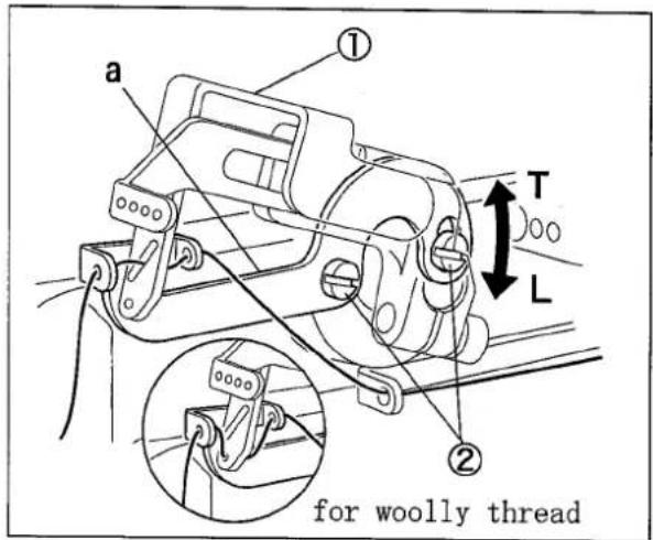
text_image
a ① T L ② for woolly threadFig. 7
4. Specifications
| Model | VF2400-8, VF2500-8 | VF2403-8, VF2503-8 |
| Description | High speed flat bed 2 or 3-needle interlock stitch machine | |
| Dimensions | 500 (L) × 250 (W) × 430 (H) mm | |
| Weight | 41 kg | |
| Stitch Type | ISO 406, 407, 602, 605 | |
| Application | Plain seam and covering for knitted fabric | Attaching collarettes or knitted binding tape |
| Sewing Speed | During intermittent operation | |
| Max. 6500 rpm | ||
| Stitch Length | 1.4 - 3.6 mmThe number of stitches 7 - 18 stitches per inch (25.4 mm)8 - 21 stitches per 30 mm | |
| Needle system | UY X 128GAS of Shumetz or Organ #65 - #90 | |
| Needle Distance | 3-needle: 4.8, 5.6, 6.0, 6.4 mm2-nnedle: 3.2, 4.0, 4.8, 6.4 mm | |
| Needle Stroke | 31 mm | |
| Presser Foot Lift | with spreader: 7.0 mmwithout spreader: 8.0 mm6.0 mm (needle distance: 6.4 mm) - 8.0 mm (3.2 mm) | without spreader: 7.0 mm5.0 mm (needle distance: 6.4 mm) - 7.0 mm (3.2 mm) |
| Feed Regulation | Push button system | |
| Differential Ratio | 1:0.7 - 1:2 | |
| Differential Feed Regulation | External lever even during operation | |
| Lubrication | Lubrication automatically by pump | |
| Lubricating Oil | YAMATO SF OIL #28 | |
| Capacity of Oil Reservoir | 1100 cc | |
| Installation | Full-submerged type and semi-submerged type | |
ILLUSTRATED SPARE PARTS LIST
VF2400-8 VF2403-8
VF2500-8 VF2503-8
7
VF2400-8, 2403-8, 2500-8, 2503-8(1)
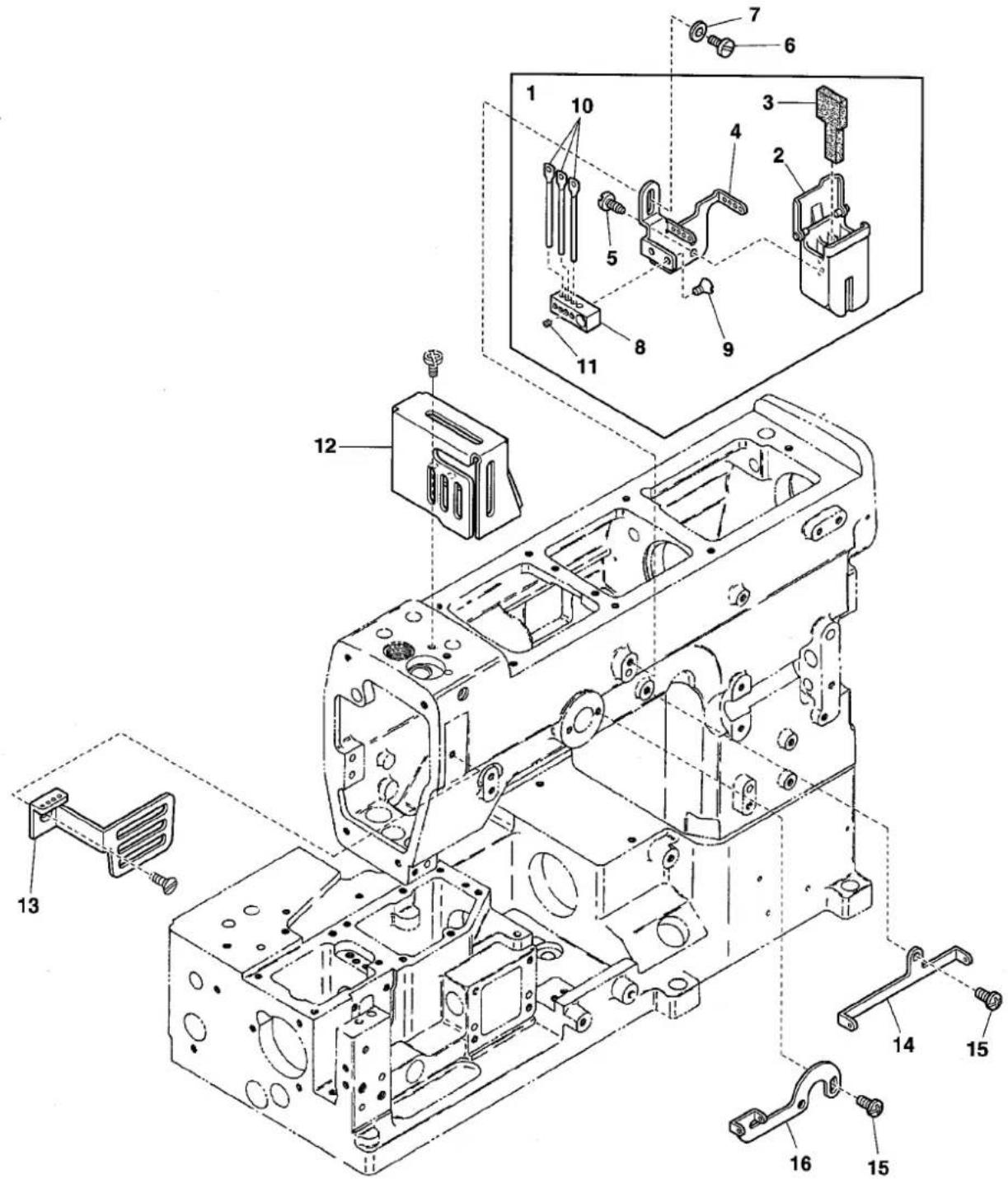
text_image
Exploded view diagram of a mechanical assembly with numbered components for identification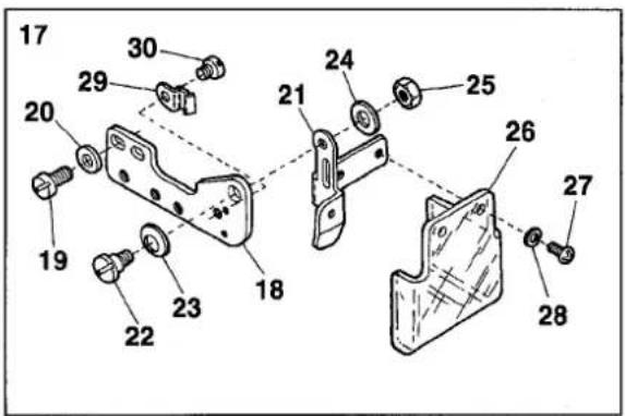
text_image
Technical diagram of a mechanical assembly with numbered parts for identification| Ref.No | Parts No. | Description | 品名 | Amt. Req |
| 1 | 3180071 | SP Device, Complete Set | SP装置(組) | 1 |
| 2 | 3100384 | SP Container | SPタンク | 1 |
| 3 | 3100386 | Felt | SPフェルト | 1 |
| 4 | 3180072 | Needle Thread Eyelet | 針糸道 | 1 |
| 5 | 350009 | Tapping Screw(3×6mm) | タッピンネジ | 2 |
| 6 | 110001 | Screw(M4-0.7×5.4) | 止ネジ | 1 |
| 7 | 000538 | Washer | ワッシャ | 1 |
| 8 | 0068247 | Needle Thread Eyelet Holder | 針糸道台 | 1 |
| 9 | 005431 | Screw(1/8-44×4.4) | 止ネジ | 2 |
| 10 | 0068249 | Needle Thread Eyelet | 針糸道 | 3 |
| 11 | 003312 | Screw(1/8-44×3.4) | 止ネジ | 3 |
| 12 | 3180074 | Needle Bar Guard | 針棒ガード | 1 |
| 13 | 3180073 | Needle Thread Take-up Guard | 針糸繰リガード | 1 |
| 14 | 3500489 | Top Cover Thread Eyelet(Right) | 飾り糸道(右) | 1 |
| 15 | 110013 | Screw(M4-0.7×8) | 止ネジ | 3 |
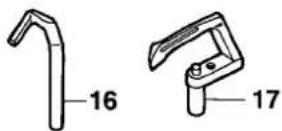
| 16 | 3180076 | Top Cover Thread Eyelet(Left) | 飾り糸道(左) | 1 |
| 17 | 3500203◆ | Eye Guard, Complete Set | アイガード(組) | 1 |
| 18 | 3500204◆ | Air Wiper Bracket | エアワイパブラケット | 1 |
| 19 | 110009◆ | Screw(M4-0.7×8) | 止ネジ | 2 |
| 20 | 000538◆ | Washer | ワッシャ | 2 |
| 21 | 3500205◆ | Eye Guard Holder | アイガード台 | 1 |
| 22 | 170044◆ | Screw(M4-0.7×7) | 止ネジ | 1 |
| 23 | 300104◆ | Conical Spring Washer | 皿パネワッシャ | 1 |
| 24 | 000663◆ | Washer | ワッシャ | 1 |
| 25 | 000022◆ | Nut | ナット | 1 |
| 26 | 3500206◆ | Eye Guard | アイガード | 1 |
| 27 | 110076◆ | Screw(M3-0.5×6) | 止ネジ | 2 |
| 28 | 000014◆ | Washer | ワッシャ | 2 |
| 29 | 3500208◆ | Stopper Spring | ストッパパネ | 1 |
| 30 | 110030◆ | Screw(M3-0.5×2.6) | 止ネジ | 1 |
2
VF2400-8, 2403-8, 2500-8, 2503-8(2)
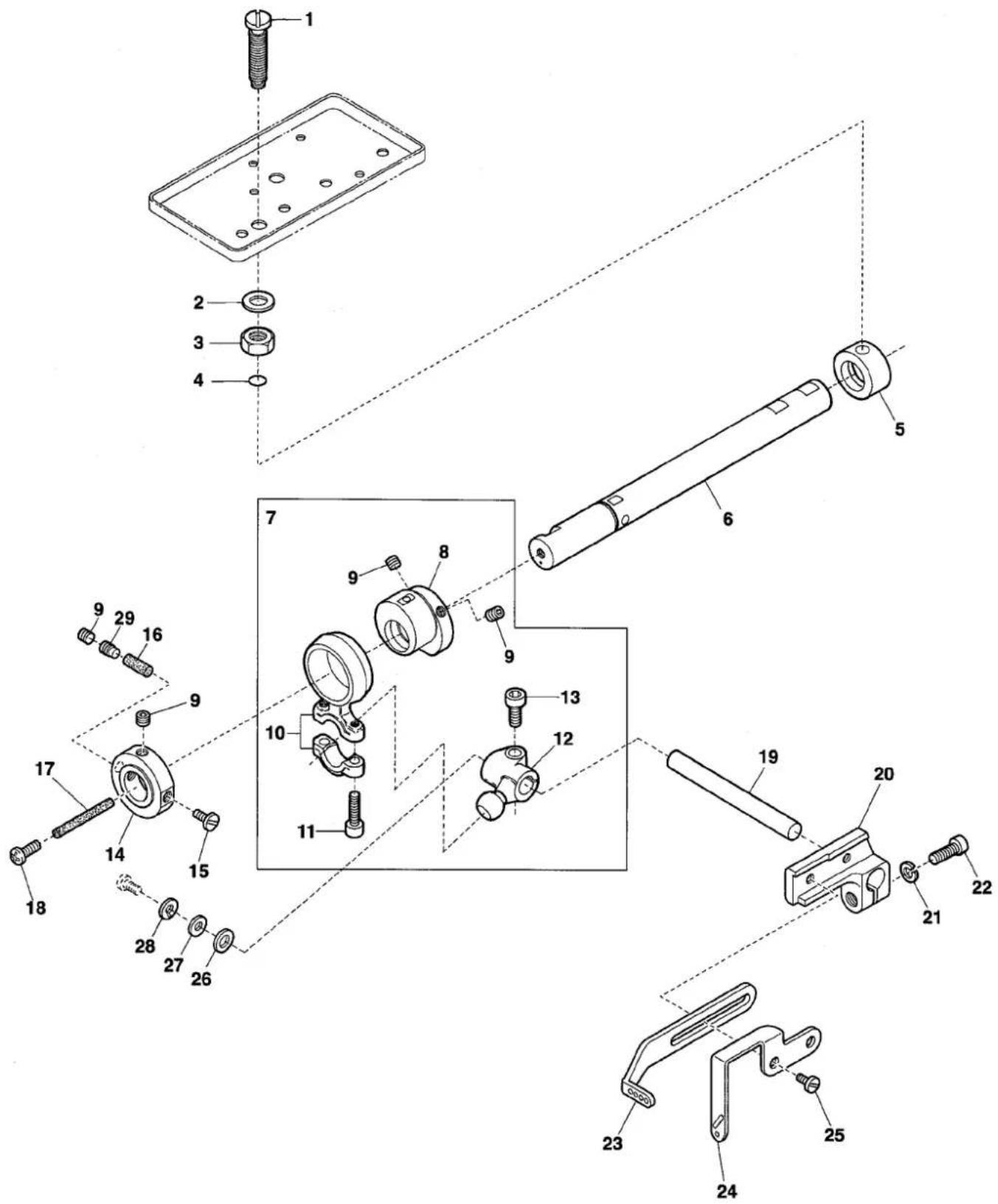
text_image
Exploded view diagram of a mechanical assembly with numbered parts for identification| Ref.No | Parts No. | Description | 品名 | Amt. Req |
| 1 | 3201532 | Oil Adjusting Screw | 給油量調節ネジ | 1 |
| 2 | 000425 | Washer | ワッシャ | 1 |
| 3 | 100003 | Nut | ナット | 1 |
| 4 | 0032518 | O-ring(P3) | Oリング | 1 |
| 5 | 3500448 | Oil Sleeve | オイルスリーブ | 1 |
| 6 | 3201533 | Upper Shaft(Left) | 上軸(左) | 1 |
| 7 | 3500444 | Connecting Rod, C. Set | 針糸繰リロッド(組) | 1 |
| 8 | 3500445 | Needle Thread Take-up Eccentric | 針糸繰リエキセン | 1 |
| 9 | 160003 | Screw(M5-0.8 × 5) | 止ネジ | 4 |
| 10 | 3500446 | Connecting Rod | 針糸繰リロッド | 1 |
| 11 | 120001 | Screw(M4-0.7 × 14) | 止ネジ | 2 |
| 12 | 3500066 | Driving Lever | 針糸繰リ軸腕 | 1 |
| 13 | 120013 | Screw(M6-1 × 15) | 止ネジ | 1 |
| 14 | 3500442 | Collar | カラー | 1 |
| 15 | 110135 | Screw(M5-0.8 × 7) | 止ネジ | 1 |
| 16 | 310132 [310124] | Oil Wick(Φ 4.2 × 16mm)[Φ 4.2 × 20mm]油芯 | 1 | |
| 17 | 310099 | Oil Wick | 油芯 | 1 |
| 18 | 110012 | Screw(M4-0.7 × 5) | 止ネジ | 1 |
| 19 | 3500065 | Driving Shaft | 針糸繰リ軸 | 1 |
| 20 | 3500492 | Bracket | 針糸繰リ台 | 1 |
| 21 | 000600 | Spring Washer | スプリングワッシャ | 1 |
| 22 | 005650 | Screw(M5-0.8 × 14) | 止ネジ | 1 |
| 23 | 3180070 | Needle Thread Take-up | 針糸繰リ糸道 | 1 |
| 24 | 3180075 | Top Cover Thread Take-up | 飾り糸繰リ | 1 |
| 25 | 110009 | Screw(M4-0.7 × 8) | 止ネジ | 2 |
| 26 | 2100218 | Spacer | スペーサ | 1 |
| 27 | 000555 | Washer | ワッシャ | 1 |
| 28 | 000600 | Spring Washer | スプリングワッシャ | 1 |
| 29 | 160041 [160003] | Screw(M5-0.8 × 8)[M5-0.8 × 5] | 止ネジ | 1 |
3
VF2400-8, 2403-8, 2500-8, 2503-8(3)
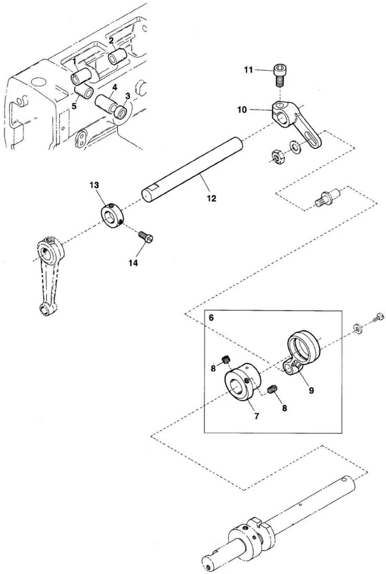
text_image
Technical diagram of a mechanical assembly with numbered parts, showing exploded and assembled views of components.| Ref.No | Parts No. | Description | 品名 | Amt. Req |
| 1 | 3500047 | Spreader Driving Shaft Bushing(Left) | 飾リ糸ルーパ軸ブッシュ(左) | 1 |
| 2 | 3500048 | Spreader Driving Shaft Bushing(Right) | 飾リ糸ルーパ軸ブッシュ(右) | 1 |
| 3 | 3500050 [2100272] | Oil Seal | オイルシール | 1 |
| 4 | 3500044 | Needle Thread Take-up Bushing(Front) | 針糸繰り軸ブッシュ(前) | 1 |
| 5 | 3500045 | Needle Thread Take-up Bushing(Rear) | 針糸繰り軸ブッシュ(後) | 1 |
| 6 | 3500081 | Spreader Eccentric, C. Set | 飾リエキセン(組) | 1 |
| 7 | 3500082 | Spreader Eccentric | 飾リエキセン | 1 |
| 8 | 160003 | Screw(M5-0.8 × 5) | 止ネジ | 2 |
| 9 | 3500084 | Spreader Connecting Rod | 飾リロッド | 1 |
| 10 | 3500086 | Spreader Adjusting Lever | 飾リ調節レバー | 1 |
| 11 | 120013 | Screw(M6-1 × 15) | 止ネジ | 1 |
| 12 | 3160138 | Driving Shaft | ルーパ軸 | 1 |
| 13 | 0032646 | Collar(12 × 20 × 8mm) | カラー | 1 |
| 14 | 009604 | Screw(11/64-40 × 5.5) | 止ネジ | 2 |
4
VF2400-8, 2500-8(4)
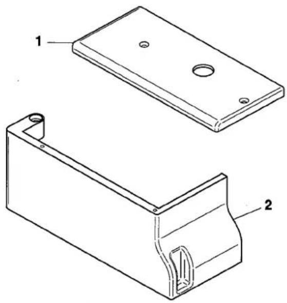
natural_image
Technical line drawing of two mechanical components with labeled parts (1 and 2), no text or symbols present.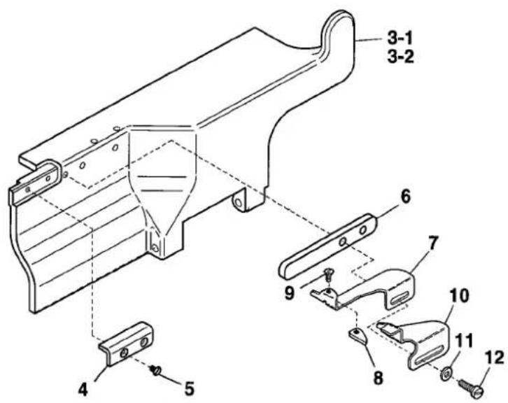
text_image
Technical diagram of a mechanical component with numbered parts, likely an assembly or assembly reference.| Ref.No | Parts No. | Description | 品名 | Amt. Req |
| 1 | 3201453 | Cloth Plate(Small) | 小カバー | 1 |
| 2 | 3201452 | Side Cover | 横開キカバー | 1 |
| 3-1 | 3201451 | Front Cover(32, 40, 48, 56) | 前開キカバー | 1 |
| 3-2 | 3201461 ◆ | Front Cover(64) | 前開キカバー | 1 |
| 4 | 3201454 | Supporting Block | 補助ブロック | 1 |
| 5 | 130002 | Screw(M3-0.5 × 6) | 止ネジ | 2 |
| 6 | 3201457 | Guide Spacer | ガイドスペーサ | 1 |
| 7 | 3100630 | Fabric Edge Guide(Left) | 定規(左) | 1 |
| 8 | 0095367 | Fabric Edge Guide Chip | 定規チップ | 1 |
| 9 | 004182 | Screw(3/32-56 × 2.5) | 止ネジ | 1 |
| 10 | 3100631 | Fabric Edge Guide(Right) | 定規(右) | 1 |
| 11 | 000538 | Washer | ワッシャ | 2 |
| 12 | 110031 | Screw(M4-0.7 × 12) | 止ネジ | 2 |
5
VF2400-8, 2500-8(5)
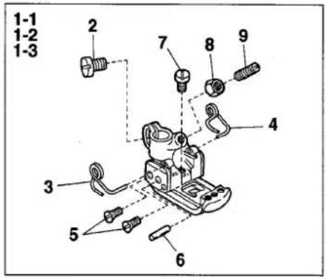
VF2400-8
text_image
1-1 1-2 1-3 2 7 8 9 4 3 5 6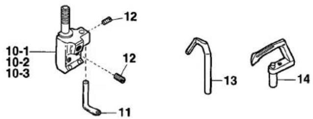
text_image
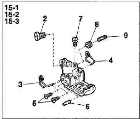
10-1 10-2 10-3 12 12 11 13 14VF2500-8
text_image
15-1 15-2 15-3 2 7 8 9 4 3 5 6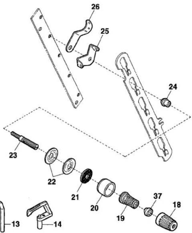
text_image
Technical diagram of a mechanical assembly with numbered parts, likely for assembly or repair instructions.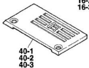
text_image
40-1 40-2 40-3EXTRA PARTS
text_image
Technical diagram showing three labeled mechanical components with numbered parts 27, 28, and 29.ACCESSORIES
text_image
Technical diagram showing exploded and assembled parts of a mechanical assembly with numbered labels| Ref.No | Parts No. | Description | 品名 | Amt. Req |
| 1-1 | 3507000 | Presser Foot, C. Set(32) | 押工(組) | 1 |
| 1-2 | 3507002 | Presser Foot, C. Set(40) | 押工(組) | 1 |
| 1-3 | 3507050 | Presser Foot, C. Set(48) | 押工(組) | 1 |
| 2 | 110004 | Screw(M3.5-0.6 × 8) | 止ネジ | 1 |
| 3 | 3107303 | Presser Foot Spring(Left) | 小押エパネ(左) | 1 |
| 4 | 3107304 | Presser Foot Spring(Right) | 小押エパネ(右) | 1 |
| 5 | 130016 | Screw(M2.5-0.45 × 6) | 止ネジ | 4 |
| 6 | 3107306 | Presser Foot Hinge Pin | 押エヒンジピン | 1 |
| 7 | 110084 | Screw(M3.5-0.5 × 4.2) | 止ネジ | 1 |
| 8 | 000327 | Lock Nut | ロックナット | 1 |
| 9 | 260006 | Adjusting Screw(1/8-44 × 9.5) | 調節ネジ | 1 |
| 10-1 | 0093351 | Needle Clamp(32) | 針止メ | 1 |
| 10-2 | 0093352 | Needle Clamp(40) | 針止メ | 1 |
| 10-3 | 0093353 | Needle Clamp(48) | 針止メ | 1 |
| 11 | 0093365 | Top Cover Thread Eyelet | 飾り糸道 | 1 |
| 12 | 001900 | Screw(1/8-44 × 2.4) | 止ネジ | 3 |
| 13 | 0093669 | Needle Guard | 針受ケ | 1 |
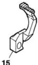
| 14 | 0094480 | Looper | ルーパ | 1 |
| 15-1 | 3507050 | Presser Foot, C. Set(48) | 押工(組) | 1 |
| 15-2 | 3507052 | Presser Foot, C. Set(56) | 押工(組) | 1 |
| 15-3 | 3507054 | Presser Foot, C. Set(64) | 押工(組) | 1 |
| 16-1 | 0093356 | Needle Clamp(48) | 針止メ | 1 |
| 16-2 | 0093357 | Needle Clamp(56) | 針止メ | 1 |
| 16-3 | 0093358 | Needle Clamp(64) | 針止メ | 1 |
| 17 | 001900 | Screw(1/8-44 × 2.4) | 止ネジ | 4 |
| 18 | 0024084 | Thread Tension Spring Cap | 糸調子パネキャップ(上) | 1 |
| 19 | 0030255 | Needle Thread Tension Spring | 糸調子パネ | 1 |
| 20 | 0090071 | Thread Tension Spring Retainer | 糸調子パネキャップ(下) | 1 |
| 21 | 000177 | Felt | フェルト | 1 |
| 22 | 0031111 | Tension Disc | 糸調子皿 | 2 |
| 23 | 290029 | Tension Pist | 糸調子棒 | 1 |
| 24 | 0090812 | Tension Post Ferrule | 糸調子棒糸摺レ | 1 |
| 25 | 0090856 | Tension Disc Eyelet | 糸調子皿糸道 | 1 |
| 26 | 0090807 | Thread Lead-in Guide | 糸調子台糸道 | 1 |
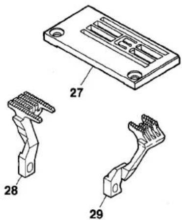
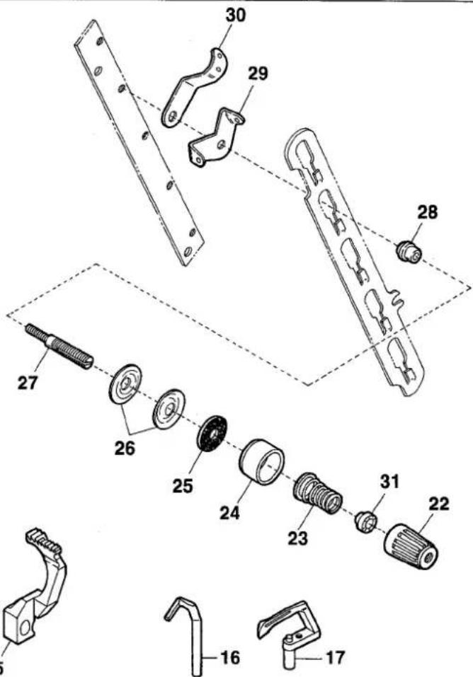
| 27 | 3508003 | Stitch Plate(56M)(Extra) | 針板(特注品) | 1 |
| 28 | 3209050 | Main Feed Dog(Extra) | 後送リ(特注品) | 1 |
| 29 | 3209085 | Differential Feed Dog(Extra) | 前送リ(特注品) | 1 |
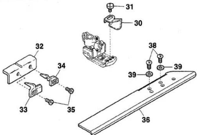
| 30 | 3107311 | Fabric Guide(Long) | 布ガイド(長) | 1 |
| 31 | 110027 | Screw(M2.5-0.45 × 3.5) | 止ネジ | 1 |
| 32 | 3201455 | Fabric Guide Support | 布ガイド取付板 | 1 |
| 33 | 3400252 | Fabric Guide(Left) | 布ガイド(左) | 1 |
| 34 | 3400253 | Fabric Guide(Right) | 布ガイド(右) | 1 |
| 35 | 110036 | Screw(M3-0.5 × 6.5) | 止ネジ | 2 |
| 36 | 3201456 | Supplementary Front Cover | 補助力バー | 1 |
| 37 | 0024083 | Tension Spring Bushing | 糸調子ナット回り止メ | 1 |
| 38 | 110105 ◆ | Screw(M5-0.8 × 12) | 止ネジ | 2 |
| 39 | 000426 ◆ | Washer | ワッシャ | 2 |
| 40-1 | 3108133 | Stitch Plate(48M) | 針板 | 1 |
| 40-2 | 3108134 | Stitch Plate(56M) | 針板 | 1 |
| 40-3 | 3108135 | Stitch Plate(64M) | 針板 | 1 |
6
VF2403-8, 2503-8(4)
text_image
Technical diagram of a mechanical assembly with numbered parts and an extra parts section view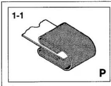
natural_image
Diagram of a folded fabric or cable component labeled '1-1' and marked with letter 'P' (no text or symbols on the diagram itself)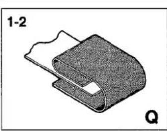
natural_image
Diagram of a mechanical component with layered structure and labeled section (no text or symbols)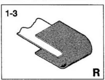
natural_image
Diagram of a mechanical component labeled '1-3' and 'R', showing layered structure without any text or symbols beyond labels| Ref.No | Parts No. | Description | 品名 | Amt. Req |
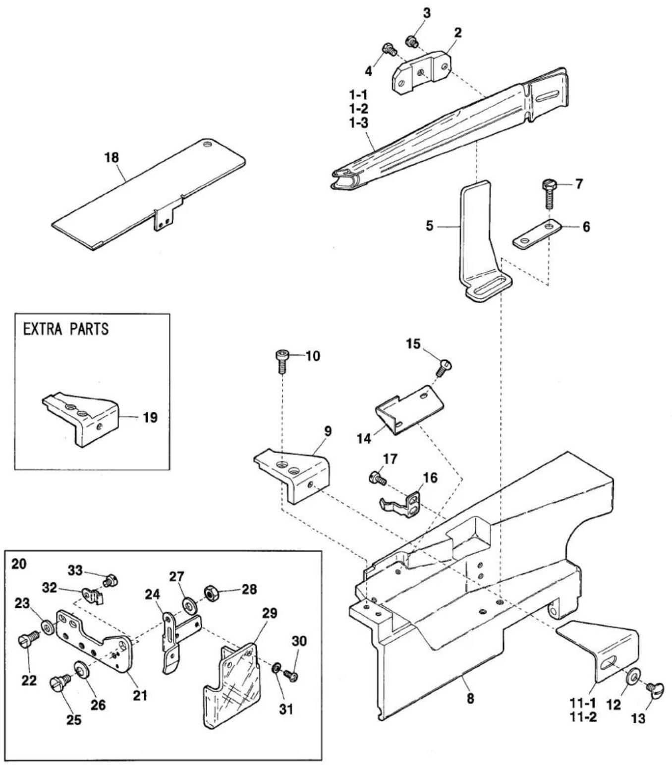
| 1-1 | 0093241 | Folder(for Type P) | 定規(P) | 1 |
| 1-2 | 0093242 | Folder(for Type Q) | 定規(Q) | 1 |
| 1-3 | 0093243 | Folder(for Type R) | 定規(R) | 1 |
| 2 | 0091736 | Folder Clamp | 定規取付片 | 1 |
| 3 | 009932 | Screw(11/64-40 × 4) | 止ネジ | 2 |
| 4 | 005554 | Screw(7/32-32 × 6.5) | 止ネジ | 1 |
| 5 | 0094245 | Folder Support | 定規取付台 | 1 |
| 6 | 0034246 | Folder Support Fixing Plate | 定規取付台固定片 | 1 |
| 7 | 140019 | Screw(M5-0.8 × 14) | 止ネジ | 2 |
| 8 | 3201000 | Front Cover | 前開キカバー | 1 |
| 9 | 3201002 | Front Cover(Small) | 前開キカバー(小) | 1 |
| 10 | 110013 | Screw(M4-0.7 × 8) | 止ネジ | 2 |
| 11-1 | 3201007 | Fabric Slide Plate | 布滑り板 | 1 |
| 11-2 | 3204047 ◆ | Fabric Slide Plate(Extra) | 布滑り板(特注品) | 1 |
| 12 | 000426 | Washer | ワッシャ | 1 |
| 13 | 110105 | Screw(M5-0.8 × 8) | 止ネジ | 1 |
| 14 | 3201005 | Dustproof Cover | 防塵カバー | 1 |
| 15 | 110104 | Screw(M4-0.7 × 8) | 止ネジ | 2 |
| 16 | 3201006 | Front Cover Spring | 前開キカバーパネ | 1 |
| 17 | 110012 | Screw(M4-0.7 × 5) | 止ネジ | 2 |
| 18 | 3201001 | Looper Thread Take-up Cover | カムカバー | 1 |
| 19 | 3201004 | Front Cover(Small)(Extra)(Note 1) | 前開キカバー(小)(特注品)(注1) | 1 |
| 20 | 3501081 ◆ | Eye Guard, Complete Set | アイガード(組) | 1 |
| 21 | 3500204 ◆ | Air Wiper Bracket | エアワイパブラケット | 1 |
| 22 | 110009 ◆ | Screw(M4-0.7 × 8) | 止ネジ | 2 |
| 23 | 000538 ◆ | Washer | ワッシャ | 2 |
| 24 | 3500205 ◆ | Eye Guard Holder | アイガード台 | 1 |
| 25 | 170044 ◆ | Screw(M4-0.7 × 7) | 止ネジ | 1 |
| 26 | 300104 ◆ | Conical Spring Washer | 皿パネワッシャ | 1 |
| 27 | 000663 ◆ | Washer | ワッシャ | 1 |
| 28 | 000022 ◆ | Nut | ナット | 1 |
| 29 | 3501080 ◆ | Eye Guard | アイガード | 1 |
| 30 | 110076 ◆ | Screw(M3-0.5 × 6) | 止ネジ | 2 |
| 31 | 000014 ◆ | Washer | ワッシャ | 2 |
| 32 | 3500208 ◆ | Stopper Spring | ストッパパネ | 1 |
| 33 | 110030 ◆ | Screw(M3-0.5 × 2.6) | 止ネジ | 1 |
Note 1: The part is for attaching label.
注1: この部品は、ラベル付け用です。
7
VF2403-8, 2503-8(5)
VF2403-8
text_image
1-1 1-2 1-3 1-4 4 3 9 8 5 6 7 2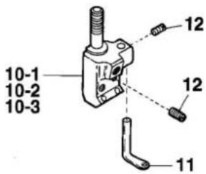
text_image
10-1 10-2 10-3 12 12 11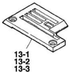
text_image
13-1 13-2 13-3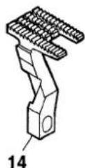
VF2503-8
text_image
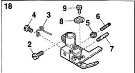
18 4 3 9 8 5 6 2 7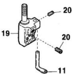
text_image
19 20 20 11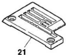
natural_image
Technical line drawing of a mechanical component with labeled part 21 (no text or symbols beyond label)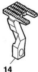
text_image
Exploded view diagram of a mechanical assembly with numbered parts for identification| Ref.No | Parts No. | Description | 品名 | Amt. Req |
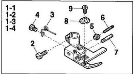
| 1-1 | 3207150 | Presser Foot, C. Set(32) | 押工(組) | 1 |
| 1-2 | 3207151 | Presser Foot, C. Set(40) | 押工(組) | 1 |
| 1-3 | 3207152 | Presser Foot, C. Set(48) | 押工(組) | 1 |
| 1-4 | 3207220 | Presser Foot, C. Set(40)(Extra) | 押工(組)(特注品) | 1 |
| 2 | 001186 | Screw(9/64-40 × 7.8) | 止ネジ | 1 |
| 3 | 0091725 | Presser Foot Spring | 小押エバネ | 1 |
| 4 | 005133 | Screw(1/8-44 × 4.5) | 止ネジ | 1 |
| 5 | 000220 | Lock Nut | ロックナット | 1 |
| 6 | 003300 | Adjusting Screw(1/8-44 × 15) | 調節ネジ | 1 |
| 7 | 0091696 | Presser Foot Hinge Pin | 押エヒンジピン | 1 |
| 8 | 3207160 | Tape Guide | テープガイド | 1 |
| 9 | 001230 | Screw(3/32-56 × 3.8) | 止ネジ | 1 |
| 10-1 | 0093351 | Needle Clamp(32) | 針止メ | 1 |
| 10-2 | 0093352 | Needle Clamp(40) | 針止メ | 1 |
| 10-3 | 0093353 | Needle Clamp(48) | 針止メ | 1 |
| 11 | 0093365 | Top Cover Thread Eyelet | 飾り糸道 | 1 |
| 12 | 001900 | Screw(1/8-44 × 2.4) | 止ネジ | 3 |
| 13-1 | 3208102 | Stitch Plate(32M) | 針板 | 1 |
| 13-2 | 3208103 | Stitch Plate(40M) | 針板 | 1 |
| 13-3 | 3208104 | Stitch Plate(48M) | 針板 | 1 |
| 14 | 3209064 | Main Feed Dog | 後送リ | 1 |
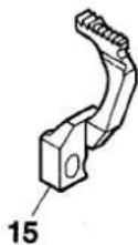
| 15 | 3209065 | Differential Feed Dog | 前送リ | 1 |
| 16 | 0093669 | Needle Guard | 針受ケ | 1 |
| 17 | 0094480 | Looper | ルーパ | 1 |
| 18 | 3207156 | Presser Foot, C. Set(56) | 押工(組) | 1 |
| 19 | 0093357 | Needle Clamp(56) | 針止メ | 1 |
| 20 | 001900 | Screw(1/8-44 × 2.4) | 止ネジ | 4 |
| 21 | 3208108 | Stitch Plate(56M) | 針板 | 1 |
| 22 | 0024084 | Thread Tension Spring Cap | 糸調子パネキャップ(上) | 1 |
| 23 | 0030255 | Needle Thread Tension Spring | 糸調子パネ | 1 |
| 24 | 0090071 | Thread Tension Spring Retainer | 糸調子パネキャップ(下) | 1 |
| 25 | 000177 | Felt | フェルト | 1 |
| 26 | 0031111 | Tension Disc | 糸調子皿 | 2 |
| 27 | 290029 | Tension Pist | 糸調子棒 | 1 |
| 28 | 0090812 | Tension Post Ferrule | 糸調子棒糸摺レ | 1 |
| 29 | 0090856 | Tension Disc Eyelet | 糸調子皿糸道 | 1 |
| 30 | 0090807 | Thread Lead-in Guide | 糸調子台糸道 | 1 |
| 31 | 0024083 | Tension Spring Bushing | 糸調子ナット回り止メ | 1 |
8
VF2403-8, 2503-8(6)
text_image
Technical diagram of a mechanical assembly with numbered components for identification| Ref.No | Parts No. | Description | 品名 | Amt. Req |
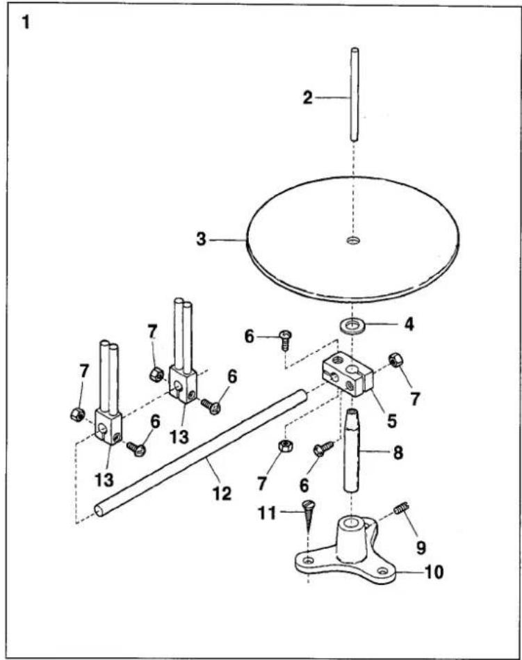
| 1 | 9620750 | Knitted Tape Stand, C. Set | メリヤステープスタンド | 1 |
| 2 | 9620751 | Tape Pin | テープ支柱 | 1 |
| 3 | 9620752 | Tape Disc | テープ受ケ板 | 1 |
| 4 | 000433 | Washer | ワッシャ | 1 |
| 5 | 9620753 | Tape Disc Block | テープ受ケ板ブロック | 1 |
| 6 | 911062 | Screw(M4-0.7 × 15) | 止ネジ | 4 |
| 7 | 910001 | Nut | ナット | 4 |
| 8 | 9620756 | Tape Stand Bar | テープスタンド棒 | 1 |
| 9 | 001448 | Screw(15/64-28 × 5.5) | 止ネジ | 1 |
| 10 | 9620757 | Tape Stand | テープスタンド | 1 |
| 11 | 005148 | Wood Screw( 4.5 × 25) | 木ネジ | 3 |
| 12 | 9620754 | Tape Guide Bar | テープガイド棒 | 1 |
| 13 | 9620755 | Tape Guide | テープガイド | 2 |
1jamato
ヤマトミシン製造株式会社
YAMATO SEWING MACHINE MFG. CO.,LTD.
4-4-12, NISHITENMA, KITA-KU, OSAKA, JAPAN
TEL:81-6-6364-1321 FAX:81-6-6364-1307
〒530-0047 大阪市北区西天満4丁目4番12号
TEL(06)6364-1321(代) FAX(06)6365-5176