VES3712-8 - Nähmaschine Yamato - Kostenlose Bedienungsanleitung
Finden Sie kostenlos die Bedienungsanleitung des Geräts VES3712-8 Yamato als PDF.


Benutzerfragen zu VES3712-8 Yamato
0 Frage zu diesem Gerät. Beantworten Sie die, die Sie kennen, oder stellen Sie Ihre eigene.
Eine neue Frage zu diesem Gerät stellen
Laden Sie die Anleitung für Ihr Nähmaschine kostenlos im PDF-Format! Finden Sie Ihr Handbuch VES3712-8 - Yamato und nehmen Sie Ihr elektronisches Gerät wieder in die Hand. Auf dieser Seite sind alle Dokumente veröffentlicht, die für die Verwendung Ihres Geräts notwendig sind. VES3712-8 von der Marke Yamato.
BEDIENUNGSANLEITUNG VES3712-8 Yamato
1jamato®
Instruction Manual
Parts List
HIGHT SPEED CYLINDER BED 3-NEEDLE INTERLOCK STITCH MACHINE
WITH LEFT-HAND TRIMMING MECHANISM
VES3712-8
Adjustments differed from VES2700-8 has been described in this book.
Read both INSTRUCTION and PARTS LIST of VES2700-8.
Before using this sewing machine, please read the instruction manual and understand the contents well.
After reading the instruction manual, please keep it in a location where it is easy to access for operators.
CONTENTS
1. Installation 1
Connecting suction pipe 1
2. Proper operation 2

2.1 Threading 2
2.2 Lubrication 3
2.3 Adjusting suction pipe(front) 4
2.4 Cleaning suction pipe 4
3. Trimming mechanism 5

3.1 Adjusting edge guide 5
3.2 Trimming width of fabric 5
3.3 Removing and installing lower knife 6
3.4 Removing and installing upper knife 6
3.5 Adjusting upper knife stroke 7
3.6 Removing and replacing trimming parts 8
4. Specifications 12
* * * * ILLUSTRATED PARTS LIST * * * *
Attention
This instruction manual is designed mainly for technicians, but it is advisable that also operators read the instructions with mark to use the machine properly.
◇The numbers in lower left corners of figures are figure numbers. We use them in texts as needed for your reference.
Attention
The description in this instruction manual is subject to change for improvements of the commodity without notice.
Connecting suction pipe
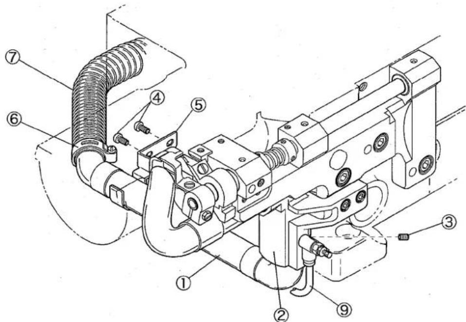
Install the the suction pipe(rear), the suction pipe holder, and the dust hose as accessories on the machine as follows:
(1) Insert the suction pipe(rear)① into the hole on the bottom of the lower knife holder bracket② and fix them with the screw③.
(2) Remove the screws④ at the rear of the machine frame.
(3) Using the screws④, fix the suction pipe support⑤ in the place the screws④ located.
(4) Set the suction pipe(rear)① on the suction pipe support⑤.
(5) Insert the dust hose⑦ fitted with the hose band⑥ into the suction pipe(rear)①, and fix the dust hose⑦ with the hose band⑥.
text_image
Technical diagram of a mechanical assembly with numbered components for identificationFig. 1
○ Using air pipe
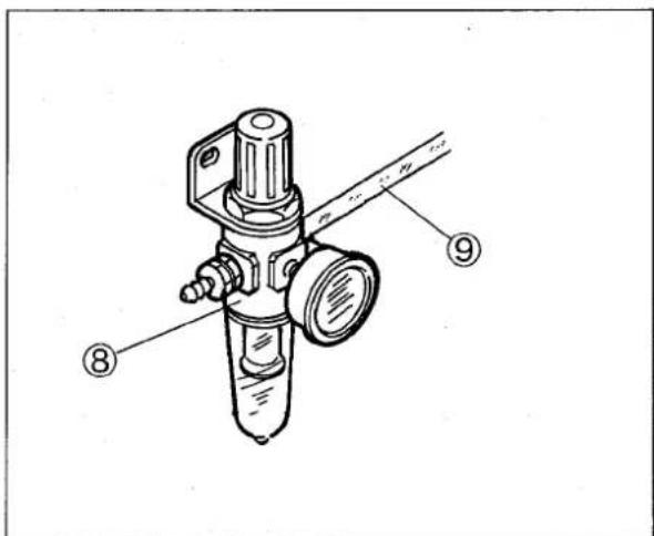
Connect the suction pipe and the air source (regulator or solenoid valve) with the air pipe ⑨.
Set the pressure of the regulator ⑧ to 0.1 - 0.2 MPa (1 - 2 kgf/cm²). With UT-A device, set it to 0.4 - 0.5 MPa (4 - 5 kgf/cm²).
○ Using vacuum system
Connect the dust hose⑦ to the vacuum system without the air pipe.
text_image
Technical diagram of a mechanical valve assembly with numbered parts labeled ⑧, ⑨, and ⑨.Fig. 2
2.1 Threading

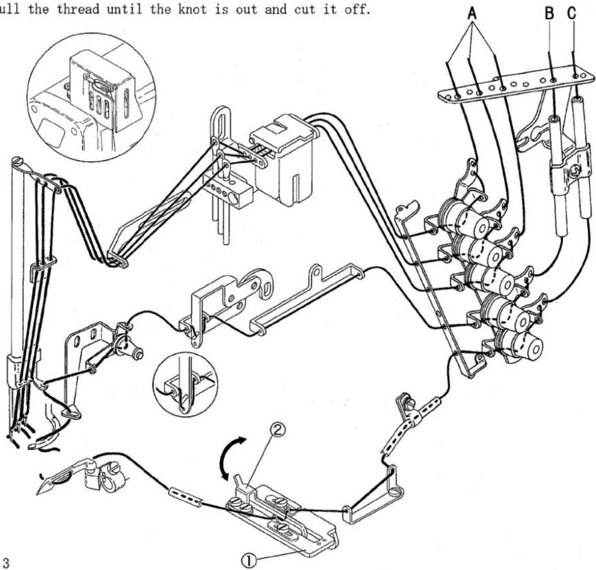
When not threaded, thread correctly as shown in Fig. 3.
When threaded, rethread after knotting preset threads.
A: Needle thread
Pull out the thread unit it is front of the needle. Then cut off the knot before needle eye to rethread.
Thread correctly for the left needle in the inmost position as shown in Fig. 3.
B: Spreader thread
Pull the thread until the knot is out.
C: Looper thread
Pull the thread until the knot is out and cut it off.
text_image
ull the thread until the knot is out and cut it off. A B C ① ② 3NOTE
For easy threading, pull the looper thread take-up eyelet support① frontward.
After threading, push the cast-off plate② to reset the looper thread take-up eyelet support① securely.
2.2 Lubrication

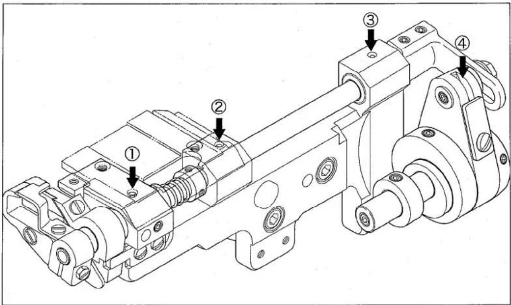
Supply oil in the trimming mechanism by hand.
○ Bearing parts: Supply a drop of oil into the holes①, ②, and ③ once or twice a day.
text_image
Technical diagram of a mechanical assembly with numbered components for identificationFig. 4
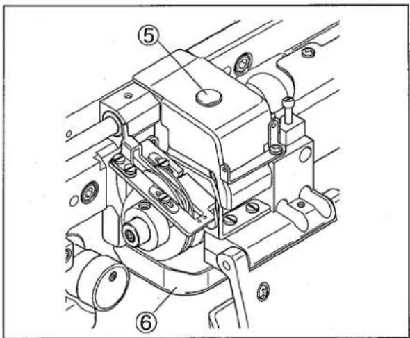
○ Rod part: Remove the seal plug ⑤ of the upper knife rod cover and supply a few drops of oil into the rod ④ once or twice a day.
NOTE
Remove and clean the upper knife rod oil receiver ⑥ once a week.
text_image
Technical diagram of a mechanical assembly with numbered components, likely a valve or pump mechanism.Fig. 5

WARNING
Before operating, ALWAYS turn the motor switch OFF and check that the motor has already stopped.
2.3 Adjusting suction pipe (front)
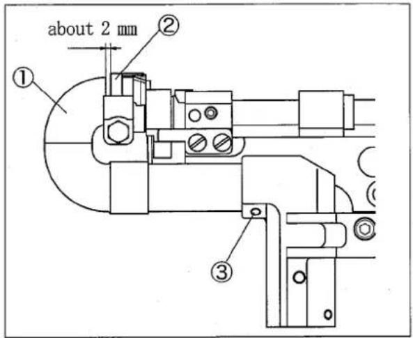
Make the clearance between the suction pipe(front) ① and the upper knife holder ② to about 2 mm to adjust left-and-right position of the suction pipe (front)①.
Loosen the screw ③ to adjust the position of the suction pipe(front)①.
text_image
about 2 mm ① ② ③Fig. 6
2.4 Cleaning suction pipe

Remove the suction pipes to clean away chips from them when clogged.
(1) Open the front cover.
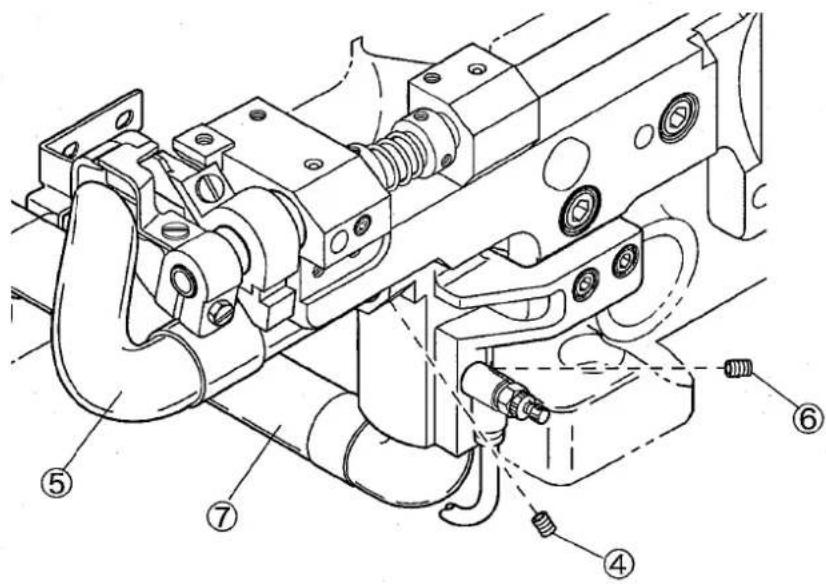
(2) Loosen the screw④ to remove the suction pipe (upper)⑤.
(3) Loosen the screw⑥ to remove the suction pipe(rear)⑦.
text_image
Technical diagram of a mechanical assembly with numbered parts for identificationFig. 7
3. Trimming mechanism
3.1 Adjusting edge guide

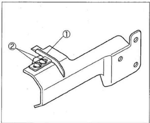
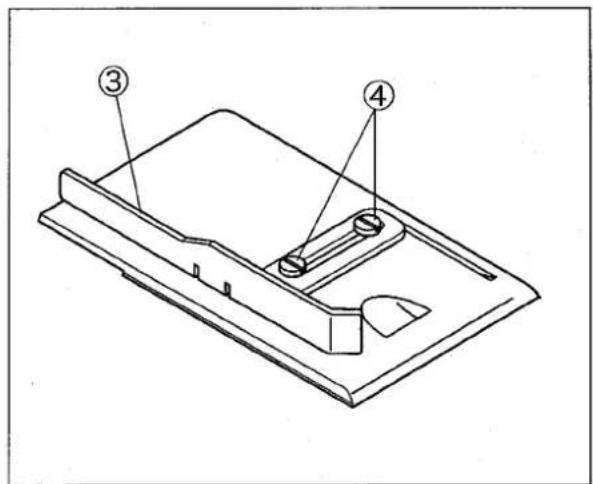
Adjust the trimming width of the fabric edge with the edge guide(left)①.
Adjust the folding width of the fabric with the edge guide(right)③.
Loosen the screws② and ④ to adjust them.
text_image
Technical diagram of a mechanical bracket with numbered annotations indicating parts ① and ②.Fig. 8
text_image
Technical diagram of a mechanical component with numbered parts labeled ③ and ④Fig. 9
3.2 Trimming width of fabric
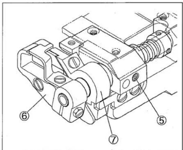
Loosen the screw⑤ to move the upper knife holder ⑥ and the lower knife holder ⑦ right or left simultaneously.
Tighten the screw⑤ securely after adjusting required position.
CAUTION
- Tightening torque is 1.5 - 2 N·m (15 - 20 kgf/cm). Do not tighten with too much torque.
- See "2.3 Adjusting suction pipe(front)" to set the position after adjusting trimming width of fabric.
text_image
Technical diagram of a mechanical assembly with numbered components labeled 5, 6, and 7Fig. 10
3.3 Removing and installing lower knife
Removing:
(1) Open the front cover.
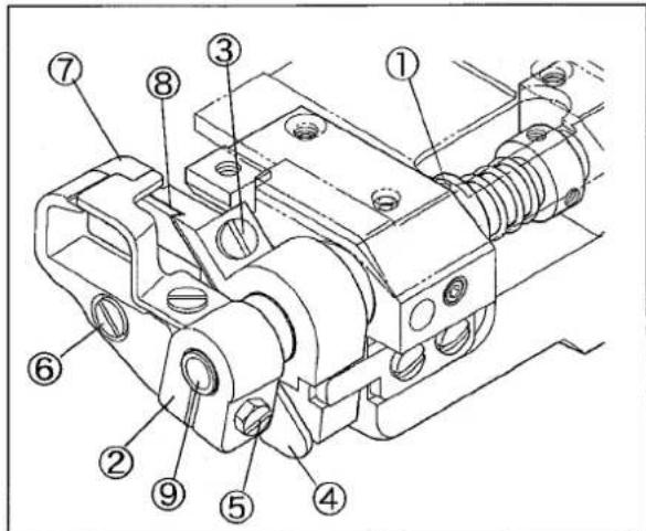
(2) Loosen two screws ① of the collar ①.
(3) Push the upper knife holder ② to the left to make a clearance between the upper and the lower knives.
(4) Tighten two screws① slightly.
(5) Loosen the screw③ to pull out the lower knife ④ downward.
Installing:
(1) Make the lower knife④ blade on a level with the top of the stitch plate. Then tighten the screw③ securely.
text_image
Technical diagram of a mechanical assembly with numbered components for identificationFig. 11
(2) Loosen two screws①. The upper knife engages with the lower knife by its spring.
(3) Check the sharpness of the baldes by setting a thread between the upper and the lower knives while rotating the pulley manually.
(4) Tighten two screws① securely.
(5) Recheck the sharpness of the blades.
3.4 Removing and installing upper knife
See Fig. 11 to follow the steps.
Removing:
(1) Loosen the screw⑤ to remove the upper knife holder②.
(2) Loosen the screw⑥ to remove the upper knife⑦.
Installing:
(1) Align the upper knife⑦ with the key groove on the upper knife holder ②. Fix them with the screw ⑥ securely.
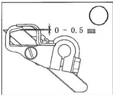
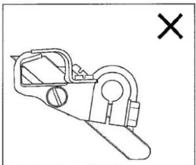
(2) Fix the upper knife holder ② to the upper knife shaft ⑨. Rotate the handwheel manually to lower the upper knife ⑦ at the lowest point. Move the upper knife holder ② so that the upper knife tip is 0 - 0.5 mm above the top surface of the lower knife ⑧. Then tighten the screw ⑤ securely.
(3) Check the sharpness of the blades by setting a thread between the upper knife⑦ and the lower knife⑧ while rotating the handwheel manually.
NOTE
Too much engagement pushes up a fabric by upper knife tip. It cannot trim fabric edge.
Fig. 12
text_image
0 - 0.5 mmFig. 13
natural_image
Line drawing of a mechanical device with a cross mark symbol (no text or labels)3.5 Adjusting upper knife stroke
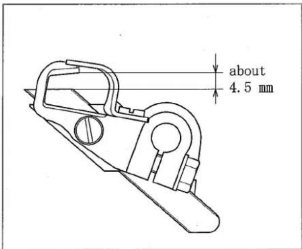
The standard stroke of the upper knife is about 4.5 mm.
Adjusting stroke:
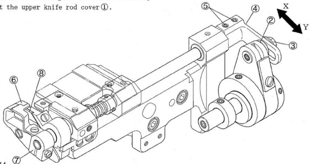
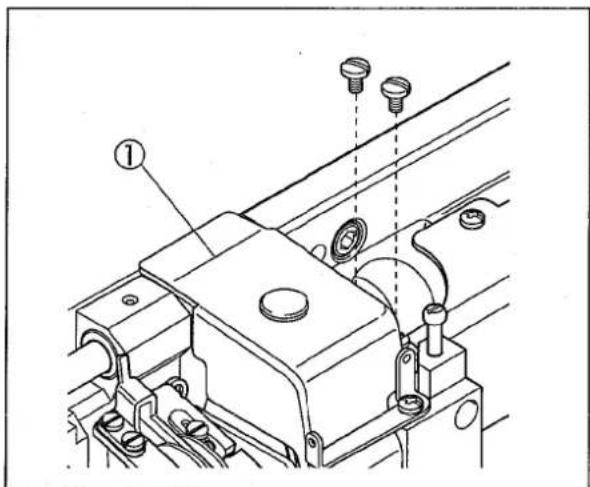
(1) Remove the upper knife rod cover①.
(2) Loosen the nut③ of the adjusting lever pin②.
(3) Move the adjusting lever pin② to adjust the stroke.
● To make the stroke large, move it in the direction X.
● To make the stroke small, move it in the direction Y.
(4) Loosen the screw③ securely.
(5) Loosen the screws⑤ on the upper knife shaft lever④.
(6) Rotate the handwheel manually to lower the upper knife⑥ at the lowest point. Move the upper knife holder⑦ so that the upper knife tip is 0 - 0.5 mm above the top surface of the lower knife⑧. Then tighten the screws⑤ securely.
(7) Check the sharpness of the blades by setting a thread between the upper⑥ and the lower⑧ knives while rotating the handwheel maunually.
(8) Reset the upper knife rod cover①.
text_image
t the upper knife rod cover①. ⑤ ④ ② ③ X Y ⑥ ⑧ ⑦ 14Fig. 14
text_image
Technical diagram of a mechanical assembly with labeled parts and alignment indicatorsFig. 15
text_image
about 4.5 mmFig. 16

WARNING
Before adjusting, ALWAYS turn the motor switch OFF and check that the motor has already stopped.
3.6 Removing and replacing trimming parts
This model can be used as VES2711-8 machine by replacing exclusive parts after removing trimming parts.
Order the stitch plate, the main feed dog, and the differential feed dog for interchanging as options.
Removing:
(1) Remove four screws① to remove the front cover②.
(2) Remove the upper knife rod cover③.
(3) Remove the upper knife rod oil receiver④.
(4) Remove the slide cover⑤.
(5) Loosen the screw⑥ to remove the suction pipe(rear)⑦.
(6) Remove the suction pipe holder⑧.
(7) Remove the stitch plate support⑨ and the stitch plate as a set.
(8) Loosen two screws⑩ of the collar.
(9) Remove the screws⑫ of the upper knife shaft lever⑪.
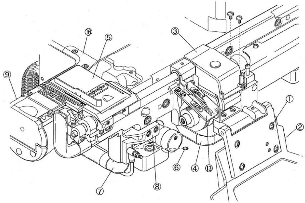
text_image
Technical diagram of a mechanical assembly with numbered components for identificationFig. 17
(10) Pull up the looper thread take-up eyelet support⑬ frontward.
(11) Remove the lower knife holder bracket⑭.
(12) Reset the looper thread take-up eyelet support⑬.
(13) Replace the main and the differential feed dogs(option).
(14) Replace the stitch plate support(accessories)⑮ and the stitch plate(option).
(15) Replace the cylinder cover(rear)⑯ with the cover(accessories)⑰.
(16) Insert the shaft lever support ^⑱ (accessories) into the upper knife shaft lever ^⑪ and fix them on the shaft lever supporting plate ^⑲ . Insert the collar (accessories) through the shaft lever support ^⑱ and fix it.
(17) Reset the upper knife rod cover③.
(18) Reset the upper knife rod oil receiver④.
(19) Replace the front cover(accessories)②.
(20) Replace the cylinder cover (accessories) ^22 .
(21) Set the fabric edge guides(right)②3 and (left)(accessories)②4.
NOTE
Keep the parts removed from the machine without missing.
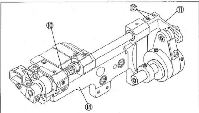
text_image
Technical diagram of a mechanical assembly with numbered components for identificationFig. 18
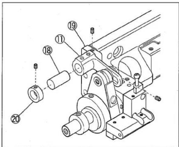
text_image
Technical diagram of a mechanical assembly with numbered components for identificationFig. 19
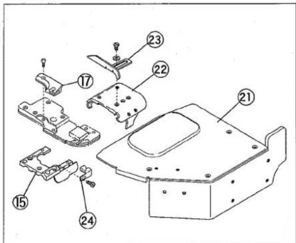
text_image
Technical diagram of a mechanical assembly with numbered parts for identificationFig. 20

WARNING
Before adjusting, ALWAYS turn the motor switch OFF and check that the motor has already stopped.
Replacing:
(1) Remove the cylinder cover①.
(2) Remove four screws② to remove the front cover③.
(3) Remove the upper knife rod cover④.
(4) Remove the upper knife rod oil receiver⑤.
(5) Remove the stitch plate support⑥, the stitch plate, and the fabric edge guide(left) as a set.
(6) Pull up the looper thread take-up eyelet support⑦ frontward.
(7) Remove the collar⑧, the screw⑨, and then the shaft lever support⑩.
(8) Insert the upper knife shaft lever⑫ into the upper knife shaft⑬ and fix the lower knife holder bracket⑭ with three screws.
(9) Tighten the screws⑮ securely.
(10) Reset the looper thread take-up eyelet support⑦.
(11) Set the suction pipe holder⑯.
(12) Fix the suction pipe (rear)⑰ with the screw⑱.
(13) Adjust the engagement of the upper knife.
(14) Adjust the engaging pressure of the knives and fix the collar⑲ with four screws⑳.
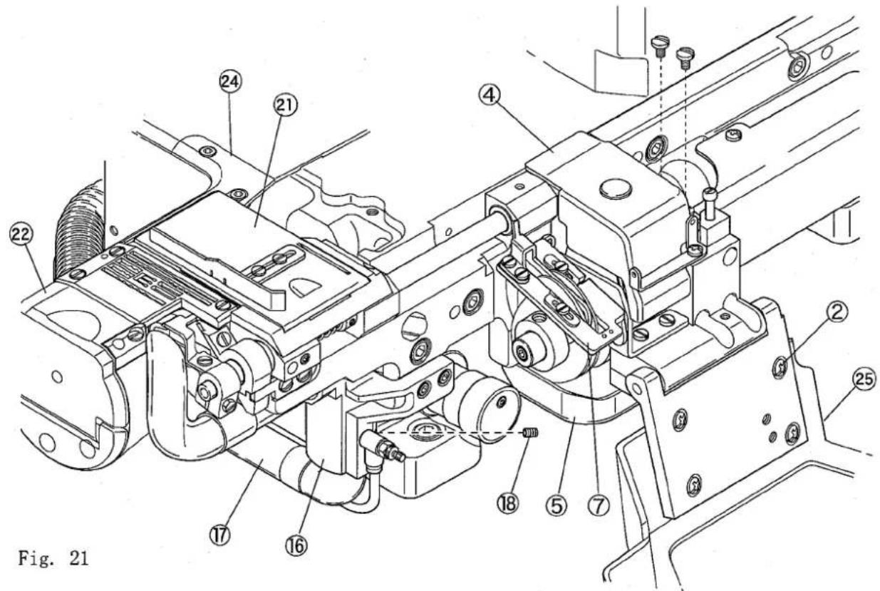
text_image
Fig. 21(15) Set the slide cover②.
(16) Replace the exclusive main and differential feed dogs.
(17) Set the exclusive stitch plate support ^22 after setting the stitch plate.
(18) Replace the cylinder cover(rear) ^23 with the exclusive cover ^24 .
(19) Reset the upper knife rod cover④.
(20) Reset the upper knife rod oil receiver⑤.
(21) Replace the exclusive front cover ^25 .
NOTE
- Keep the parts removed from the machine without missing.
- See "3.4 Removing and installing upper knife" to adjust the engagement of the knives.
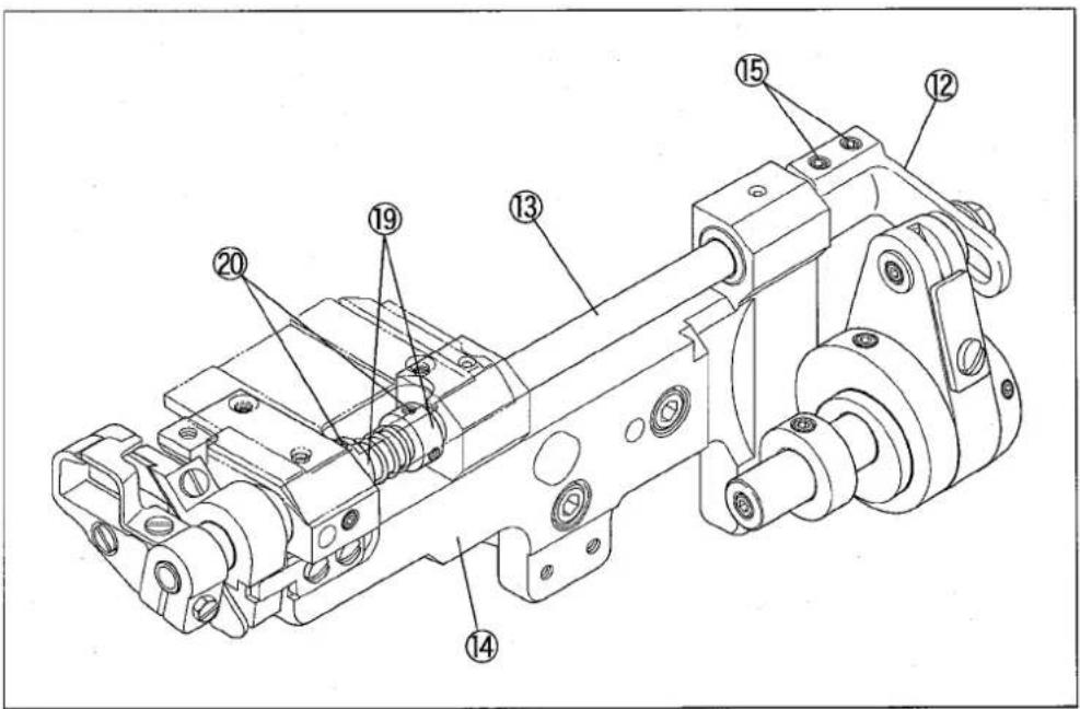
text_image
Technical diagram of a mechanical assembly with numbered components for identificationFig. 22
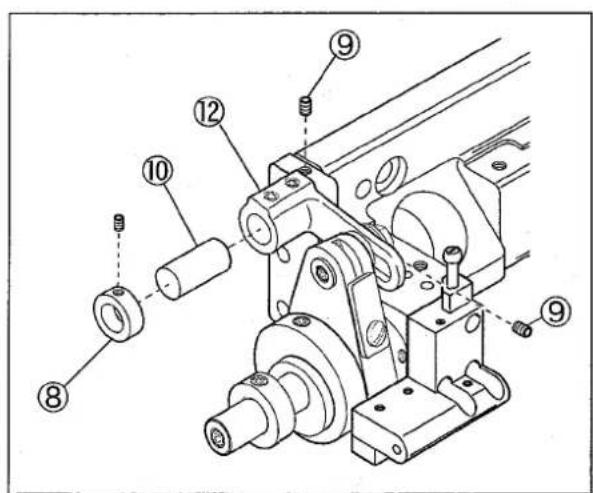
text_image
Technical diagram of a mechanical assembly with numbered components for identificationFig. 23
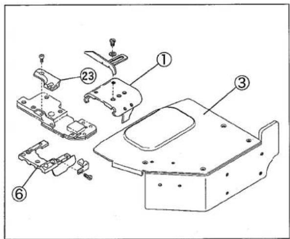
text_image
Technical diagram of a mechanical assembly with numbered parts, likely for assembly or manufacturing purposes.Fig. 24
| Model | VES3712-8 |
| Description | High speed cylinder bed 3-needle interlock stitch machine with variable top feeder and left-hand trimming mechanism |
| Dimensions | 451 mm (L) × 274 mm (W) × 423 mm (H) |
| Outer Circumference of Cylinder | 265 mm |
| Weight | 50 kg |
| Stitch Type | ISO 406, 407, 602, 605 |
| Application | Hemming operation of knitted or woven fabrics |
| Sewing Speed | Up to 4500 rpm (during intermittent operation) |
| Stitch Length | 1.4 - 4.2 mmNumber of stitches per inch(25.4 mm) 6 - 18 stitchesper 30 mm 7 - 21 stitches |
| Needle System | UY×128GAS #65 - 90 (#9 - 14) |
| Needle Distance | 4.8 mm, 5.6 mm |
| Needle Stroke | 31 mm |
| Upper Knife Stroke | 4.5 - 7.0 mm (at shipment: 4.5 mm) |
| Suction of Chips | Venturi (standard) or vacuum (option) system |
| Presser Foot Lift | Max. 5.5 mm (without spreader: 7.5 mm) |
| Feed Regulation | By lever (or by adjusting screw) |
| Differential Ratio | Max. normal differential: 1:1.4Max. reverse differential: 1:0.8 |
| Differential Feed Regulation | Adjustable by control lever (banana type, adjustable with screwdriver) |
| Movements of top feed dog | Front-and-rear movements: 1.6 - 7.0 mmUp-and-down movements: standard: 4 mm, 3.5 - 6.0 mm (with spreader: max. 5 mm) |
| Lubricating Oil | YAMATO SF OIL #28 |
| Lubrication | Lubrication automatically by trochoid-shaped pump with splash system |
| Capacity of Oil Reservoir | 800 ml |
| Installation | Table top type, or semi-submerged type (with exclusive supporting board) |
ILLUSTRATED SPARE PARTS LIST
VES3712-8
1
VES3712-8(1)
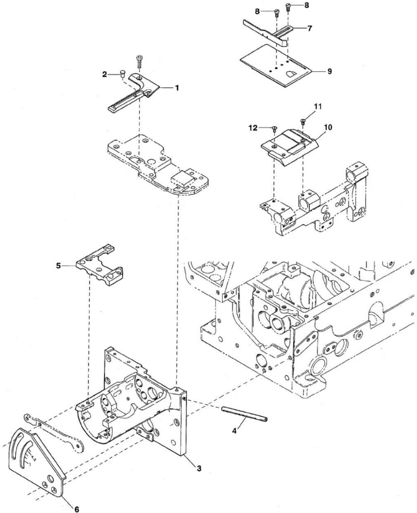
text_image
Exploded view diagram of a mechanical assembly with numbered components for identification| Ref.No | Parts No. | Description | 品名 | Amt. Req |
| 1 | 3150455 | Cylinder Cover(Rear) | シリンダカバー(後) | 1 |
| 2 | 3200033 | Cushion | クッション | 1 |
| 3 | 3150404 | Cylinder | シリンダ | 1 |
| 4 | 3150465 | Thread Eyelet Pipe | 糸道パイプ | 1 |
| 5 | 3150408 | Stitch Plate Support | 針板取付板 | 1 |
| 6 | 3150447 | Feed Graduations | 送り目盛板 | 1 |
| 7 | 3150444 | Fabric Edge Guide(Right) | 裾引キガイド(右) | 1 |
| 8 | 110101 | Screw(M3-0.5 × 3) | 止ネジ | 2 |
| 9 | 3150441 | Slide Cover | 滑り板 | 1 |
| 10 | 3150440 | Slide Cover Holder | 滑り板台 | 1 |
| 11 | 130028 | Screw(M3-0.5 × 2) | 止ネジ | 1 |
| 12 | 130023 | Screw(M3-0.5 × 3.5) | 止ネジ | 1 |
2
VES3712-8(2)
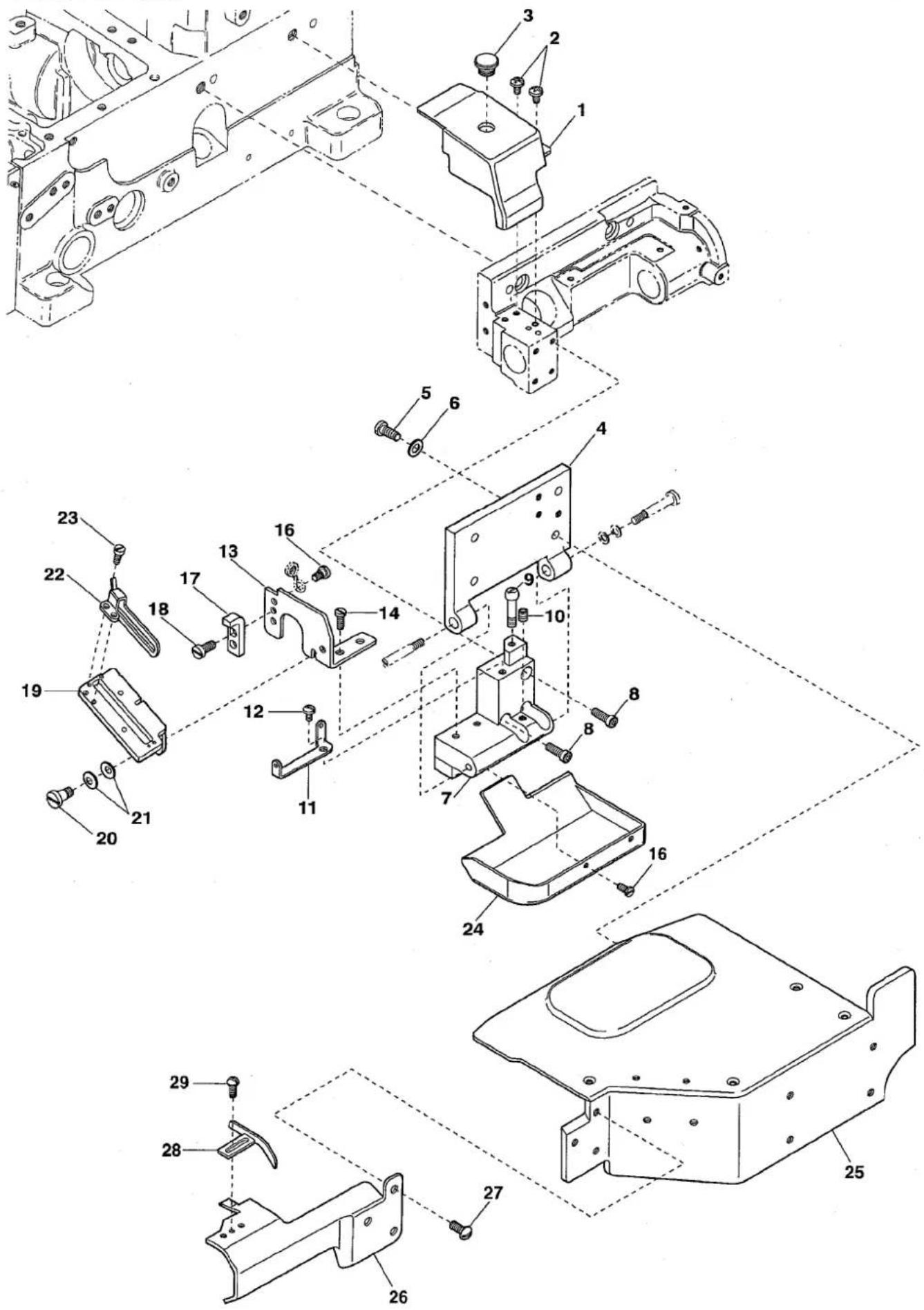
text_image
Technical diagram of a mechanical assembly with numbered parts for identification and assembly reference.| Ref.No | Parts No. | Description | 品名 | Amt. Req |
| 1 | 3150431 | Upper Knife Rod Cover | 上メスロッドカバー | 1 |
| 2 | 110012 | Screw(M4-0.7 × 5) | 止ネジ | 2 |
| 3 | 3150442 | Seal Plug | 詰栓 | 1 |
| 4 | 3150407 | Front Cover Hinge | 前開キカバーヒンジ | 1 |
| 5 | 110013 | Screw(M4-0.7 × 8) | 止ネジ | 4 |
| 6 | 001123 | Washer | ワッシャ | 4 |
| 7 | 3150406 | Front Cover Hinge Bracket | 前開キカバーヒンジ台 | 1 |
| 8 | 120001 | Screw(M4-0.7 × 14) | 止ネジ | 3 |
| 9 | 190078 | Screw(M4-0.7 × 5) | バネ掛ケネジ | 1 |
| 10 | 160001 | Screw(M4-0.7 × 4) | 止ネジ | 1 |
| 11 | 3150466 | Hinge Bracket Eyelet | ヒンジ台糸道 | 1 |
| 12 | 110012 | Screw(M4-0.7 × 5) | 止ネジ | 1 |
| 13 | 3150435 | Looper Thread Take-up Eyelet Bracketカム糸道台 | 1 | |
| 14 | 110009 | Screw(M4-0.7 × 8) | 止ネジ | 2 |
| 15 | ||||
| 16 | 110002 | Screw(M3-0.5 × 5) | 止ネジ | 3 |
| 17 | 3150437 | Take-up Eyelet Support Stop | カム糸道取付板ストッパ | 1 |
| 18 | 007627 | Screw(M4-0.7 × 6) | 止ネジ | 2 |
| 19 | 3150436 | Looper Thread Take-up Eyelet Support | カム糸道取付板 | 1 |
| 20 | 170010 | Screw(M4-0.7 × 4) | 止ネジ | 1 |
| 21 | 300100 | Conical Spring Washer | 皿パネワッシャ | 2 |
| 22 | 3150438 | Cast-off Plate | ルーパ糸案内 | 1 |
| 23 | 110054 | Screw(M3-0.5 × 3.5) | 止ネジ | 2 |
| 24 | 3150430 | Upper Knife Rod Oil Receiver | 上メスロッド油受ケ | 1 |
| 25 | 3150450 | Front Cover Unit | 前開キカバー(組) | 1 |
| 26 | 3150457 | Bracket Cover | ブラケットカバー | 1 |
| 27 | 110104 | Screw(M4-0.7 × 8) | 止ネジ | 3 |
| 28 | 3150443 | Fabric Guide(Left) | 布ガイド(左) | 1 |
| 29 | 110101 | Screw(M3-0.5 × 3) | 止ネジ | 2 |
3
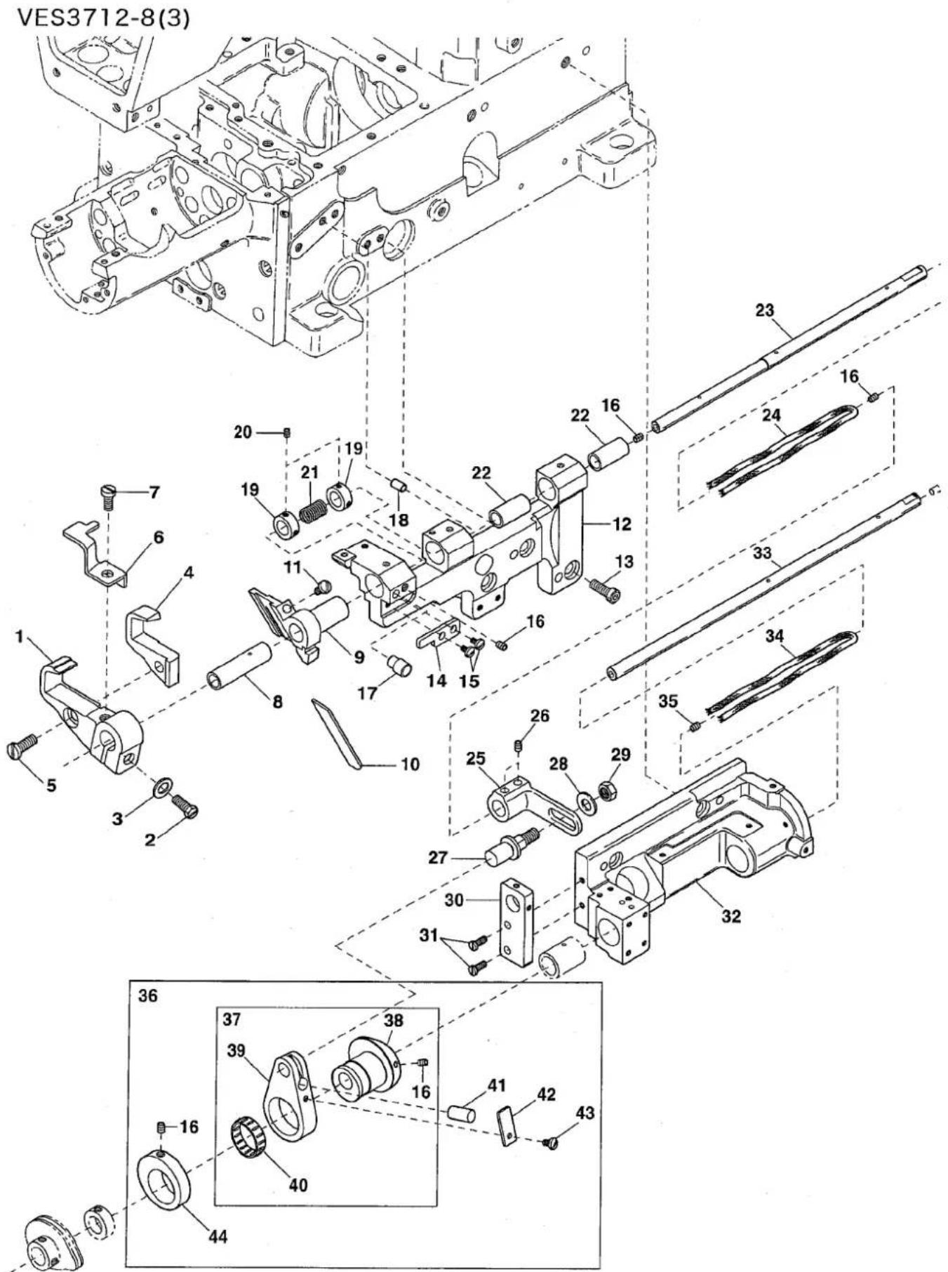
text_image
VES3712-8(3) 1 2 3 4 5 6 7 8 9 10 11 12 13 14 15 16 17 18 19 20 21 22 23 24 25 26 27 28 29 30 31 32 33 34 35 36 37 38 39 40 41 42 43 44| Ref.No | Parts No. | Description | 品名 | Amt. Req |
| 1 | 3150425 | Upper Knife Holder | 上メス台 | 1 |
| 2 | 140019 | Screw(M5-0.8 × 14) | 止ネジ | 1 |
| 3 | 300000 | Washer | ワッシャ | 1 |
| 4 | 3150426 | Upper Knife | 上メス | 1 |
| 5 | 110035 | Screw(M4-0.7 × 10) | 止ネジ | 1 |
| 6 | 4150427 | Upper Knife Cover | 上メスカバー | 1 |
| 7 | 110001 | Screw(M4-0.7 × 5.4) | 止ネジ | 1 |
| 8 | 3150416 | Lower Knife Holder Bushing | 下メス台ブッシュ | 1 |
| 9 | 3150413 | Lower Knife Holder | 下メス台 | 1 |
| 10 | 3150415 | Lower Knife | 下メス | 1 |
| 11 | 110010 | Screw(M4-0.7 × 16) | 止ネジ | 1 |
| 12 | 3150411 | Lower Knife Holder Bracket | 下メス台ブラケット | 1 |
| 13 | 120013 | Screw(M6-1 × 15) | 止ネジ | 3 |
| 14 | 3150414 | Lower Knife Holder Guide | 下メス台ガイド | 1 |
| 15 | 110009 | Screw(M4-0.7 × 8) | 止ネジ | 2 |
| 16 | 006212 | Screw(M5-0.8 × 6) | 止ネジ | 7 |
| 17 | 3150486 | Cushion | クッション | 1 |
| 18 | 000779 | Knock Pin | ノックピン | 1 |
| 19 | 3200086 | Collar(8 × 13 × 6mm) | カラー | 2 |
| 20 | 1600000 | Screw(M3-0.5 × 3) | 止ネジ | 4 |
| 21 | 0094577 | Upper Knife Spring | 上メスバネ | 1 |
| 22 | 3150412 | Upper Knife Shaft Bushing | 上メス軸ブッシュ | 2 |
| 23 | 3150424 | Upper Knife Shaft | 上メス軸 | 1 |
| 24 | 310128 | Oil Wick(400mm) | 油芯 | 1 |
| 25 | 3150423 | Upper Knife Shaft Lever | 上メス軸腕 | 1 |
| 26 | 160003 | Screw(M5-0.8 × 5) | 止ネジ | 2 |
| 27 | 3100309 | Adjusting Lever Pin | 調節レバービン | 1 |
| 28 | 000528 | Washer | ワッシャ | 1 |
| 29 | 100003 | Nut | ナット | 1 |
| 30 | 3150476 | Shaft Lever Supporting Plate | 軸腕支工取付板 | 1 |
| 31 | 110035 | Screw(M4-0.7 × 10) | 止ネジ | 2 |
| 32 | 3150405 | Take-up Shaft Bracket | カム軸ブラケット | 1 |
| 33 | 3150434 | Take-up Shaft | カム軸 | 1 |
| 34 | 310127 | Oil Wick(340mm) | 油芯 | 1 |
| 35 | 160015 | Screw(M6-1 × 6) | 止ネジ | 1 |
| 36 | 3150419 | Upper Knife Rod, C. Set | 上メスロッド(組) | 1 |
| 37 | 3150420 | Upper Knife Rod, C. Set(1) | 上メスロッド(組1) | 1 |
| 38 | 3150433 | Upper Knife Eccentric | 上メスエキセン | 1 |
| 39 | 3150421 | Upper Knife Rod | 上メスロッド | 1 |
| 40 | 0068146 | Roller Bearing | ニードルベアリング | 1 |
| 41 | 3150439 | Oil Wick | 油芯 | 1 |
| 42 | 3150429 | Upper Knife Rod Rid | 上メスロッド蓋 | 1 |
| 43 | 110054 | Screw(M3-0.5 × 3.5) | 止ネジ | 1 |
| 44 | 3150432 | Collar | カラー | 1 |
4
VES3712-8(4)
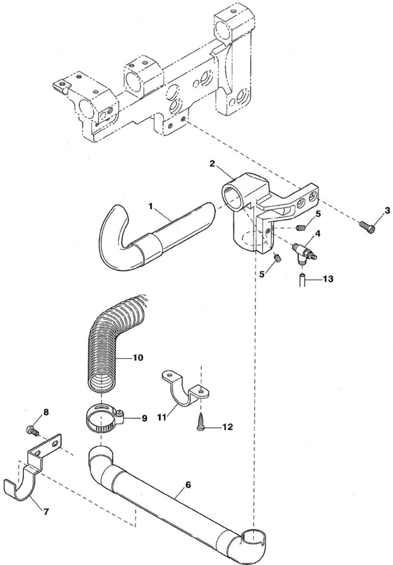
text_image
Technical diagram of a mechanical assembly with numbered parts for identification| Ref.No | Parts No. | Description | 品名 | Amt. Req |
| 1 | 3150468 | Suction Pipe(Upper) Unit | 吸込管(上)(組) | 1 |
| 2 | 3150460 | Suction Pipe Holder | 吸込管取付台 | 1 |
| 3 | 120009 | Screw(M4-0.7 × 12) | 止ネジ | 2 |
| 4 | 1095002 | Speed Controller | スピードコントローラ | 1 |
| 5 | 160001 | Screw(M4-0.7 × 4) | 止ネジ | 2 |
| 6 | 3501552 | Suction Pipe(Rear) Unit | 吸込管(後)(組) | 1 |
| 7 | 3150473 | Suction Pipe Holder | 吸込管支工 | 1 |
| 8 | 004127 | Screw(M4-0.7 × 6) | 止ネジ | 2 |
| 9 | 1253061 | Hose Clamp | ホースクランプ | 1 |
| 10 | 0012480 | Dust Hose(1500mm) | 集塵ホース | 1 |
| 11 | 0013648 | Hose Band | ホースバンド | 1 |
| 12 | 006921 | Wood Screw( 4.8 × 25) | 木ネジ | 2 |
| 13 | 1096030 | Air Tube(6 × 4mm)(Black) | エアチューブ(黒) | - |
5
VES3712-8(5)
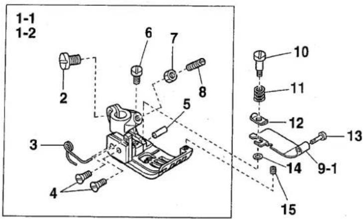
text_image
1-1 1-2 2 6 7 8 5 3 4 10 11 12 13 14 9-1 15EXTRA PARTS
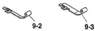
natural_image
Two mechanical bracket diagrams labeled 9-2 and 9-3, showing different end configurations (no text or symbols beyond labels)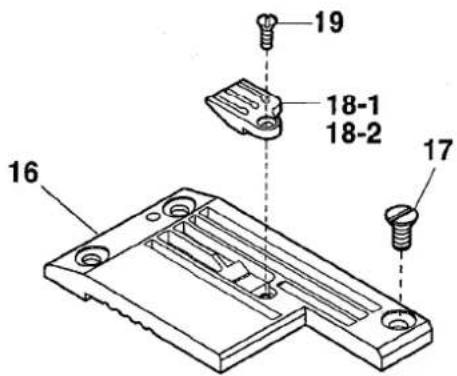
text_image
16 17 18-1 18-2 19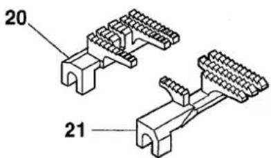
text_image
20 21| Ref.No | Parts No. | Description | 品名 | Amt. Req |
| 1-1 | 3517002 | Presser Foot, C. Set(48) | 押工(組) | 1 |
| 1-2 | 3517003 | Presser Foot, C. Set(56) | 押工(組) | 1 |
| 2 | 110004 | Screw(M3.5-0.6×8) | 止ネジ | 1 |
| 3 | 3107303 | Presser Foot Spring(Left) | 小押エバネ(左) | 1 |
| 4 | 130016 | Screw(M2.5-0.45×6) | 止ネジ | 2 |
| 5 | 3247022 | Presser Foot Hinge Pin(56) | 押エヒンジピン | 1 |
| 6 | 110084 | Screw(M3.5-0.5×4.2) | 止ネジ | 1 |
| 7 | 000327 | Lock Nut | ロックナット | 1 |
| 8 | 003302 | Adjusting Screw(1/8-44×11) | 調節ネジ | 1 |
| 9-1 | 3517039 | Fabric Presser (width 25.4mm) | 布押工 | 1 |
| 9-2 | 3517037 | Fabric Presser (width 15.9mm)(Extra) | 布押工(特注部品) | 1 |
| 9-3 | 3517038 | Fabric Presser (width 19mm)(Extra) | 布押工(特注部品) | 1 |
| 10 | 170058 | Screw(M2-0.4×2.5) | 止ネジ | 1 |
| 11 | 3517031 | Fabric Presser Spring | 布押エバネ | 1 |
| 12 | 2150112 | Spring Holder | バネ受ケ | 1 |
| 13 | 3517032 | Fabric Presser Shaft | 布押工軸 | 1 |
| 14 | 300068 | Washer | ワッシャ | 1 |
| 15 | 160033 | Screw(M2.5-0.45×3) | 止ネジ | 1 |
| 16 | 3528000 | Stitch Plate | 針板 | 1 |
| 17 | 009142 | Screw(9/64-40×4.8) | 止ネジ | 1 |
| 18-1 | 3508154 | Stitch Plate Tongue(48S8) | 針板爪 | 1 |
| 18-2 | 3508155 | Stitch Plate Tongue(56S8) | 針板爪 | 1 |
| 19 | 004182 | Screw(3/32-56×2) | 止ネジ | 1 |
| 20 | 3159081 | Main Feed Dog | 後送リ | 1 |
| 21 | 3159083 | Differential Feed Dog | 前送リ | 1 |
6
VES3712-8(6)
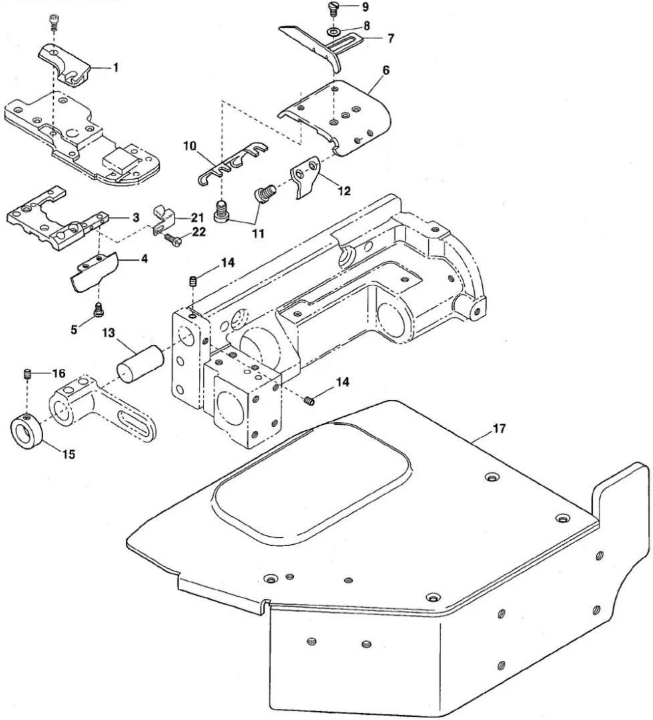
text_image
Exploded view diagram of a mechanical assembly with numbered parts for identificationEXTRA PARTS
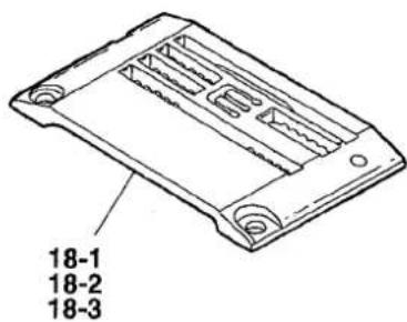
text_image
18-1 18-2 18-3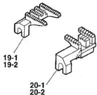
text_image
19-1 19-2 20-1 20-2| Ref.No | Parts No. | Description | 品名 | Amt. Req |
| 1 | 3150102 | Cylinder Cover(Rear) | シリンダカバー(後) | 1 |
| 2 | ||||
| 3 | 3150181 | Stitch Plate Support | 針板台 | 1 |
| 4 | 3150485 | Cylinder Cover(Lower) | シリンダカバー(下) | 1 |
| 5 | 001230 | Screw(3/32-56 × 3.8) | 止ネジ | 2 |
| 6 | 3150095 | Cylinder Upper Cover | シリンダ上カバー | 1 |
| 7 | 3150165 | Fabric Edge Guide(Right) | 裾引キガイド(右) | 1 |
| 8 | 000533 | Washer | ワッシャ | 2 |
| 9 | 007627 | Screw(M4-0.7 × 6) | 止ネジ | 2 |
| 10 | 3150097 | Cylinder Upper Cover Spring(Rear) | シリンダ上カバーバネ(後) | 1 |
| 11 | 110091 | Screw(M3-0.5 × 3) | 止ネジ | 4 |
| 12 | 3150096 | Cylinder Upper Cover Spring(Front) | シリンダ上カバーバネ(前) | 1 |
| 13 | 3150477 | Shaft Lever Support | 軸腕支工軸 | 1 |
| 14 | 160001 | Screw(M4-0.7 × 4) | 止ネジ | 2 |
| 15 | 0032719 | Collar(10 × 16 × 6mm) | カラー | 1 |
| 16 | 001459 | Screw(9/64-40 × 3) | 止ネジ | 1 |
| 17 | 3150480 | Front Cover Unit | 前開キカバー(組) | 1 |
| 18-1 | 3158063 | Stitch Plate(40M) | 針板 | 1 |
| 18-2 | 3158064 | Stitch Plate(48M) | 針板 | 1 |
| 18-3 | 3158065 | Stitch Plate(56M) | 針板 | 1 |
| 19-1 | 3159038 | Main Feed Dog(40, 48) | 後送り | 1 |
| 19-2 | 3159037 | Main Feed Dog(56) | 後送り | 1 |
| 20-1 | 3159041 | Differential Feed Dog(40, 48) | 前送り | 1 |
| 20-2 | 3159040 | Differential Feed Dog(56) | 前送り | 1 |
| 21 | 3155010 | Fabric Edge Guide(Left) | 裾引キガイド(左) | 1 |
| 22 | 110007 | Screw(M2.5-0.45 × 6) | 止ネジ | 1 |
Lamato
ヤマトミシン製造株式会社
YAMATO SEWING MACHINE MFG. CO., LTD.
4-4-12, NISHITENMA, KITA-KU, OSAKA, JAPAN
TEL:81-6-6364-1321 FAX:81-6-6364-1307
〒530-0047 大阪市北区西天満4丁目4番12号
TEL(06)6364-1321(代) FAX(06)6365-5176