CF2339M-1 - Nähmaschine Yamato - Kostenlose Bedienungsanleitung
Finden Sie kostenlos die Bedienungsanleitung des Geräts CF2339M-1 Yamato als PDF.


| Produkttyp | Hochgeschwindigkeits-Flachbett-Interlock-Nähmaschine mit rechtsseitigem Stoffabschneider und Kupplungstyp-Messvorrichtung |
| Abmessungen (L×B×H) | 500 × 250 × 430 mm |
| Gewicht | 46 kg |
| Maximale Nähgeschwindigkeit | 5000 U/min |
| Standard Nähgeschwindigkeit | 4500 U/min (200 Stunden Einlaufzeit bei 4300 U/min) |
| Stichart | ISO 406, 407, 602, 605 |
| Nadeltyp | UY128GAS #10 – #14 |
| Nadelabstand (2-Nadel) | 3,2 mm / 4,0 mm / 4,8 mm |
| Nadelabstand (3-Nadel) | 5,6 mm / 6,4 mm |
| Stichlänge | 1,4 – 3,6 mm (7 – 18 Stiche pro Zoll, 8 – 21 Stiche pro 30 mm) |
| Differenzialverhältnis | 1:0,7 – 1:2 |
| Presser Foot Lift (parallel) | 4,0 mm (mit Spreizer) |
| Stoffabschneider | Rechtsseitig mit Ober- und Untermesser |
| Messvorrichtung (Metering Device) | Kupplungstyp, maximale Bandbreite 70 mm |
| Schmierung | Automatisch durch Pumpe |
| Öltyp | YAMATO SF OIL #28 |
| Ölbehälterkapazität | 1100 ccm |
| Installationsart | Halbversenkt (Semi-submerged) |
| Konformität | PL-Gesetz und CE-Kennzeichnung |
Häufig gestellte Fragen - CF2339M-1 Yamato
Benutzerfragen zu CF2339M-1 Yamato
0 Frage zu diesem Gerät. Beantworten Sie die, die Sie kennen, oder stellen Sie Ihre eigene.
Eine neue Frage zu diesem Gerät stellen
Laden Sie die Anleitung für Ihr Nähmaschine kostenlos im PDF-Format! Finden Sie Ihr Handbuch CF2339M-1 - Yamato und nehmen Sie Ihr elektronisches Gerät wieder in die Hand. Auf dieser Seite sind alle Dokumente veröffentlicht, die für die Verwendung Ihres Geräts notwendig sind. CF2339M-1 von der Marke Yamato.
BEDIENUNGSANLEITUNG CF2339M-1 Yamato
1jamato®
Instruction Manual
HIGH SPEED FLAT BED INTERLOCK STITCH MACHINE
WITH RIGHT HAND FABRIC TRIMMER AND METERING DEVICE
CF2339M-1
This instruction manual shows adjustments different from those of CF2300M.
Read this manual and that of CF2300M.
SAVE ALL the INSTRUCTION MANUALS. READ and UNDERSTAND them THOROUGHLY for SAFE USE.
CONTENTS
Safety instructions
-
Sewing speed 1
-
Installation 2
2.1 Supporting board (Semi-submerged type) 2
2.2 Table cutting diagram (Semi-submerged type) 3
- Proper operation 4
3.1 Threading 4
3.2 Setting elastic tape 5
3.3 Feeding amount of elastic tape 6
- Adjustments 7
4.1 Chip guard and presser foot tape guide 7
4.2 Tape guide 7
4.3 Pressure of elastic feed roller 8
4.4 Maintenance of metering device 8
4.5 Trimming width 9
4.6 Trimming mechanism 10
4.6.1 Installing and removing lower knife 10
4.6.2 Installing and removing upper knife 10
4.6.3 Engagement between upper and lower knives 11
4.6.4 Sharpening knives 11
- Specifications 12
Attention
This instruction manual is designed mainly for technicians, but it is advisable that also operators read the instructions with mark to use the machine properly.
◇The numbers in lower left corners of figures are figure numbers. We use them in texts as needed for your reference.
Attention
The description in this instruction manual is subject to change for improvements of the commodity without notice.
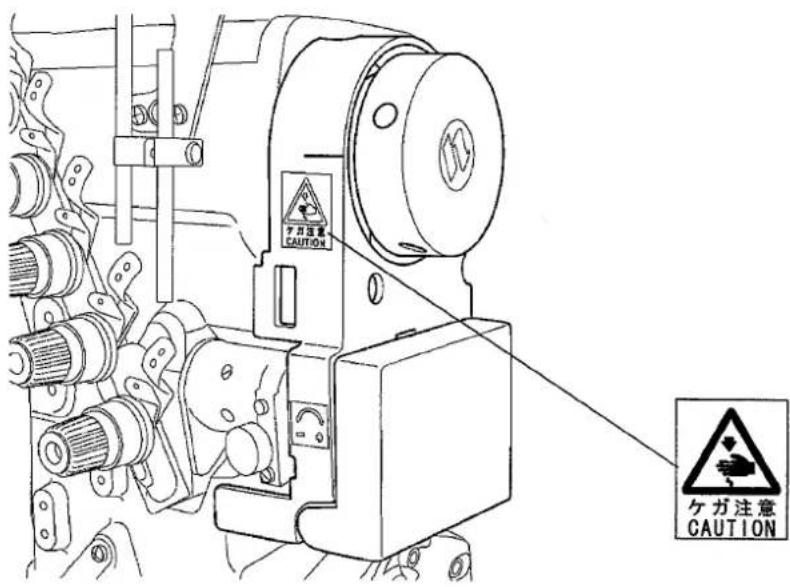
Warning label on sewing machine
metering devicwe
text_image
ケガ注意 CAUTION ケガ注意 CAUTION1. Sewing speed
Maximum sewing speed is 5000 rpm and standard speed is 4500 rpm.
Run a new machine at 4300 rpm during the first 200 hours (for about one month) so that the machine can offer a long service life in good condition.
2. Installation
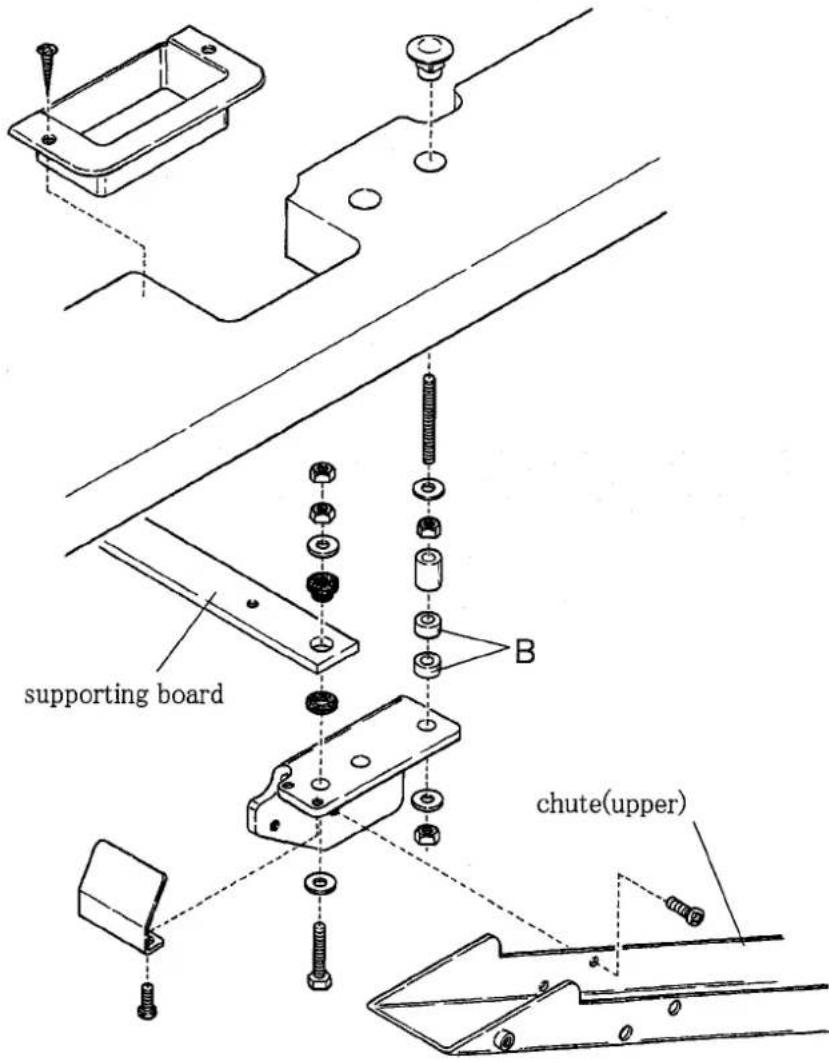
2.1 Supporting board (Semi-submerged type)
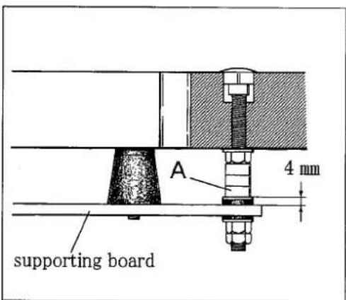
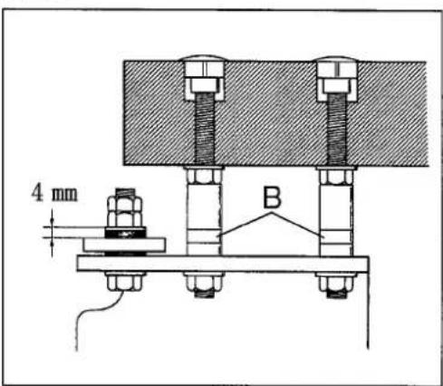
Install a machine correctly referring to Figs. 1, 2, and 3.
Set the screws in the supporting board and cover the screws with the rubber cushions. Fix the the supporting board to the machine table and install a machine securely on the rubber cushions.
text_image
supporting board chute(upper)Fig. 1
text_image
supporting board A 4 mmFig. 2
| Thickness of table | Pcs. of A | Pcs. of B |
| 40 mm | 3 pcs. × 3 = 9 | 2 pcs. × 2 = 4 |
| 45 mm | 2 pcs. × 3 = 6 | 1 pc. × 2 = 2 |
| 50 mm | 1 pc. × 3 = 3 | 0 |
Table 1
text_image
4 mm BFig. 3
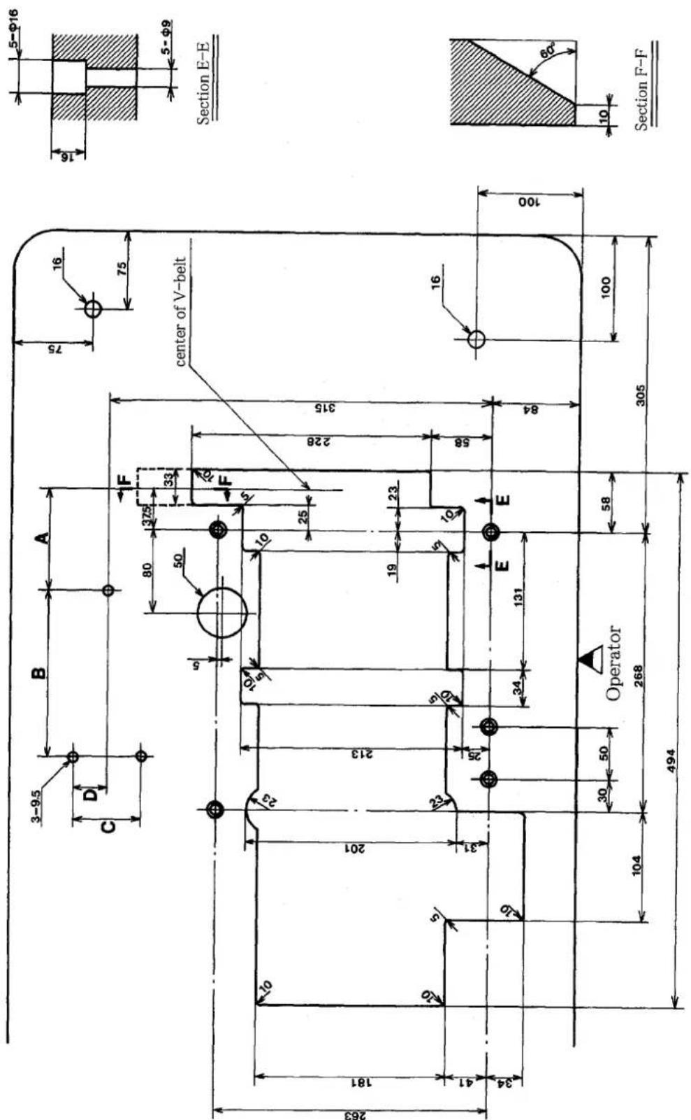
2.2 Table cutting diagram (Semi-submerged type)
text_image
3-9.5 B A 75 16 75 C D 80 375 F 50 33 5 F 20 center of V-belt Section E-E 263 181 201 213 10 10 23 10 25 228 315 19 23 E E 16 41 31 24 25 34 131 84 100 30 50 Operator 58 104 268 305 100 494 Section F-FRefer to the instruction manual of the motor for dimensions A, B, C, and D.
Fig. 4
3. Proper operation
3.1 Threading

WARNING
Before operating, ALWAYS turn the motor switch OFF and check that the motor has already stopped.
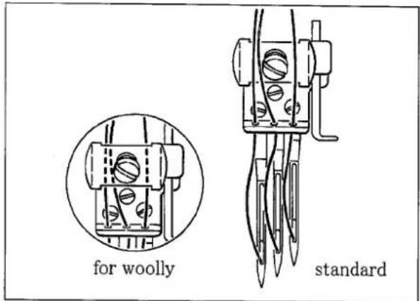
Set the needle thread retainer disc to the needle clamp on this machine.
Thread through the needles as shown in Fig. 5.
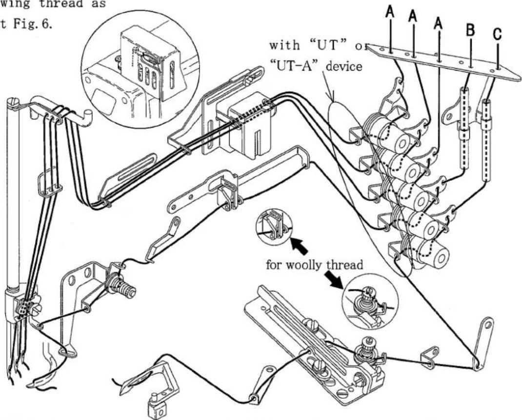
When not threaded, thread correctly as shown in Fig. 7. When threaded, rethread after knotting preset threads.
A: Needle thread
Pull out the thread until it is in front of the needle. Then cut off the knot before needle eye to rethread.
Thread correctly for the left needle in the inmost position as shown in Fig.7.
B: Top cover thread
Pull the thread until the knot is out.
C: Looper thread
Pull the thread until the knot is out. Then cut off the knot.
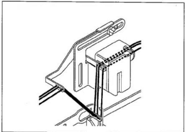
Tighten needle thread, when light material is sewing. The following thread as shown in a right Fig. 6.
text_image
for woolly standardFig. 5
natural_image
Technical line drawing of a mechanical clamp or bracket assembly (no text or symbols)Fig. 6
text_image
wing thread as t Fig.6. with "UT" or "UT-A" device for woolly threadFig. 7
3.2 Setting elastic tape
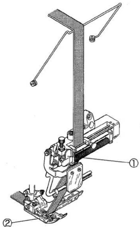
Set a tape correctly referring to Fig. 10.
Pressing the roller lever ① will make a clearance between the rollers.
Pull a tape through the bottom of the presser foot ②.
text_image
Technical diagram of a mechanical device with labeled parts, showing assembly structure and component annotations.Fig. 8
3.3 Feeding amount of elastic tape
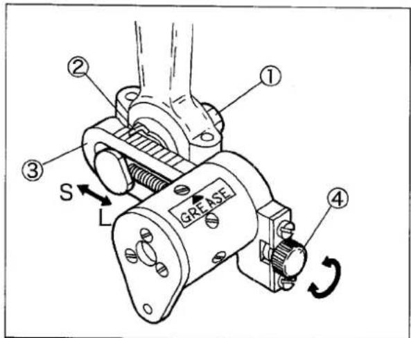
Loosen the nut① and adjust feeding amount while checking the pointer ② and the graduations of the clutch lever ③ as below.
● To increase feeding amount, turn the adjusting screw ④ clockwise and move the pointer ② in the direction “L”.
● To decrease feeding amount, turn the adjusting screw④ counterclockwise and move the pointer ② in the direction “S”.
Note: After tightening the nut ①, turn the adjusting screw ④ clockwise to tighten it securely without play.
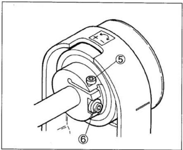
If required feeding amount cannot be obtained, loosen the screw ⑤ and adjust it as below.
● To decrease feeding amount, turn the adjusting screw⑥ clockwise.
● To increase feeding amount, turn the adjusting screw ⑥ counterclockwise.
text_image
① ② ③ S GREASE ④Fig. 9
text_image
Technical diagram of a mechanical assembly with numbered components labeled ⑤, ⑥, and ⑦Fig. 10
4. Adjustments

WARNING
Before adjusting, ALWAYS turn the motor switch OFF and check that the motor has already stopped.
4.1 Chip guard and presser foot tape guide
Adjust the lace guide(left)① right or left depending on the needle distance and a part to be sewn on a tape.
Set the lace guide(right)② depending on a tape width.
Loosen the screws ③④ to adjust them.
Set the chip guard ⑤ depending on a trimming width.
Loosen the screw⑥ to set it near the upper knife as closely as possible.

text_image
Technical diagram of a mechanical assembly with numbered components for identificationFig. 11
4.2 Tape guide
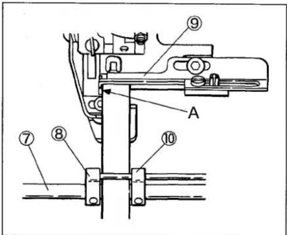
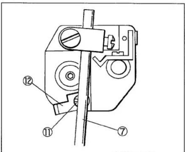
(1) Set the tape guide bar(long)⑦ to a low position enough for sewing.
(2) Set the inside of the tape guide, c. set⑧ along “A” on the lace guide(left)⑨. Set the tape guide ⑩ to guide a tape smoothly depending on a tape width.
(3) After positioning the tape guide bar(long)⑦, loosen the screw ⑪ to position the tape guide stopper ⑫.
It prevents the needle bar from touching the tape guide, c. set ⑧ and makes the position of the tape guide bar (long) ⑦.
text_image
Technical diagram of a mechanical assembly with numbered components and labeled parts A and 9Fug. 12
text_image
Technical diagram of a mechanical device with numbered components labeled ①, ②, and ⑦.Fig. 13

WARNING
Before adjusting, ALWAYS turn the motor switch OFF and check that the motor has already stopped.
4.3 Pressure of elastic feed roller
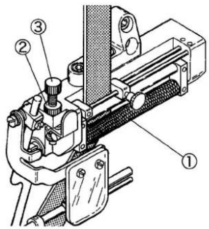
To adjust the pressure of elastic tape with tension roller (small)①, loosen the lock nut② and turn the adjusting screw ③.
● To increase the pressure, turn the adjusting screw ③ clockwise.
● To decrease the pressure, turn it counterclockwise.
Keep the pressure as low as possible.
Too tight or loose pressure can cause uneven feeding of a tape.
REFERENCE
Too much change in tension of a tape from the bobbin may occur uneven sewing finish size even if the tension roller(large) feeds an elastic tape correctly.
An automatic elastic feeder "AEF-31" can feed an elastic tape smoothly and constant sewing finish can be obtained.
4.4 Maintenance of metering device
Replacement and repair:
Improper installation of the metering device can cause improper feeding of an elastic tape, skip stitch, needle breakage, bad sewing performance and others.
Carefully install the device as following points:
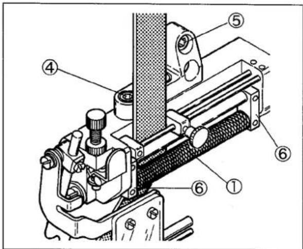
(1) Check that the roller shaft turns smoothly after setting it. Loosen the screws ④ and ⑤ and make interlining to adjust it.
(2) Set the tension roller(small)① to turn smoothly like a top. Improper turning of it can cause irregular feeding of a tape.
(3) Set the tension link ⑥ and its shaft to turn smoothly.
(4) Set the tension spring pressure of the tension roller (small)① as low as possible so that it can follow the rotation.
Lubrication:
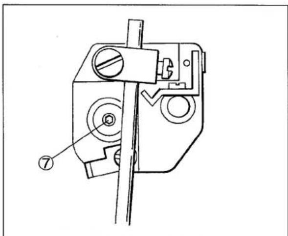
Remove the screws⑦ on the roller shaft to supply with grease on each part several times a year.
text_image
Technical diagram of a mechanical clamp or measuring device with numbered components labeled ①, ②, and ③.Fig. 14
text_image
Technical diagram of a mechanical device with numbered components for identificationFig. 15
text_image
Technical diagram of a mechanical device with numbered component annotationsFig. 16

WARNING
Before adjusting, ALWAYS turn the motor switch OFF and check that the motor has already stopped.
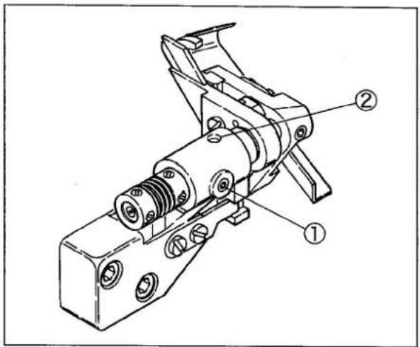
4.5 Trimming width
Open the side cover and loosen the screw ①. Then, the upper and lower knife holders move right and left at the same time.
Tighten the screw ① after adjusting the position.
(Supply a few drops of oil into the oil hole ② if needed.)
text_image
Technical diagram of a mechanical device with numbered annotations indicating parts ① and ②.Fig. 17

WARNING
Before adjusting, ALWAYS turn the motor switch OFF and check that the motor has already stopped.
4.6 Trimming mechanism
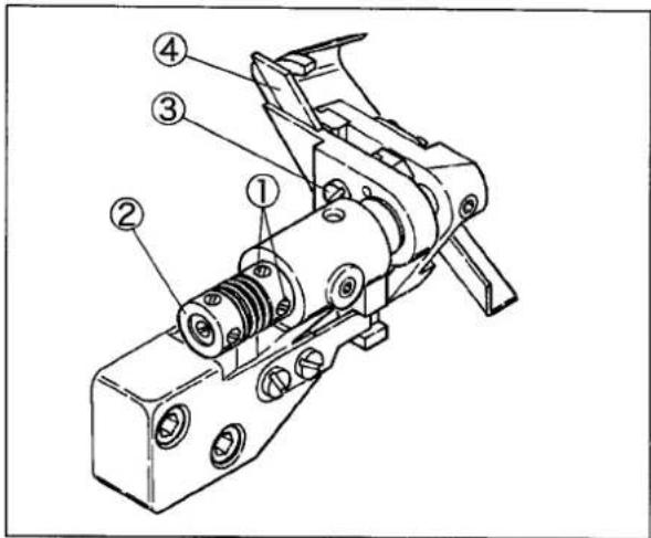
4.6.1 Installing and removing lower knife
Removing lower knife:
(1) Loosen the screws ① of the collar(right).
(2) Push the collar(left)② to the right to make the clearance between the upper and lower knives.
(3) Tighten the screws ① slightly.
(4) Loosen the screw ③ of the lower knife clamp and pull it out the lower knife ④.
Installing lower knife:
(1) Position the lower knife ④ tip even with the top of the stitch plate and tighten the screw ③ securely.
(2) Loosen the screws①. (The upper knife engages with the lower knife by the spring.)
(3) Put a thread between the upper and lower knives to check the sharpness of them while turning the pulley manually.
(4) Tighten the screws ① securely.
(5) Recheck the sharpness of the knives.
text_image
Technical diagram of a mechanical device with numbered components for identificationFig. 18
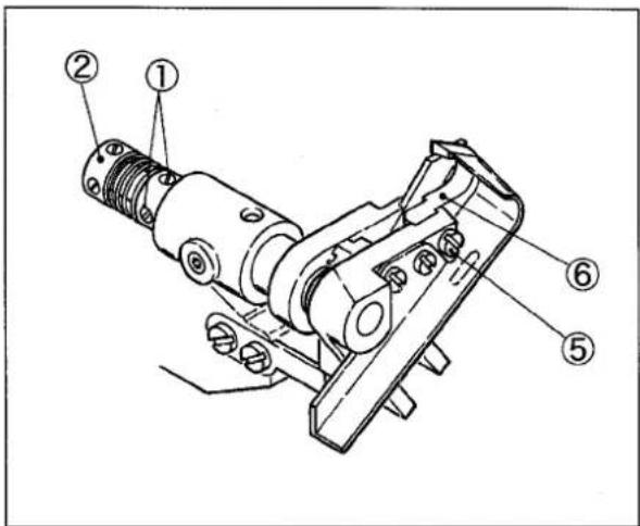
4.6.2 Installing and removing upper knife
Removing upper knife:
(1) Loosen the screws ①.
(2) Push the collar(left)② to the right to make the clearance between the upper and lower knives.
(3) Tighten the screws ① slightly.
(4) Loosen the screw ⑤ to remove the upper knife ⑥.
Installing upper knife:
(1) Install the upper knife ⑥ with the screw ⑤.
(2) Loosen the screws①. (The upper knife engages with the lower knife by the spring.)
(3) Put a thread between the upper and lower knives to check the sharpness of them while turning the pulley manually.
(4) Tighten the screws ① securely.
(5) Recheck the sharpness of the knives.
text_image
Technical diagram of a mechanical assembly with numbered components labeled ①, ②, and ⑤.Fig. 19

WARNING
Before adjusting, ALWAYS turn the motor switch OFF and check that the motor has already stopped.
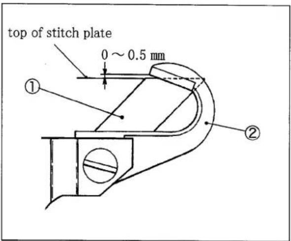
4.6.3 Engagement between upper and lower knives
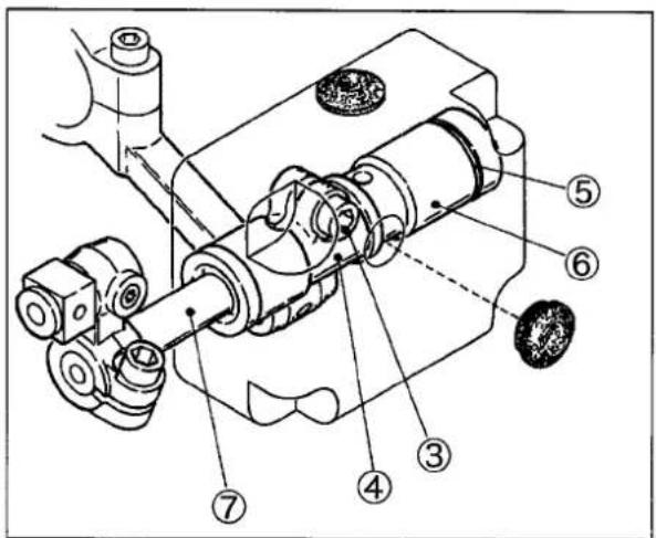
The upper knife② engages with the lower knife① as shown in Fig. 25 when the upper knife moves to the lowest point. Loosen the screw ③ and move the upper knife ② and the upper knife holder up or down to adjust it.
Hold the upper knife driving shaft bushings ⑥ with the upper knife driving shaft lever(right)④ and the spacer⑤ without palying the upper knife shaft ⑦ right or left.
Then, tighten the screw ③ securely.
text_image
top of stitch plate 0 ~ 0.5 mm ① ②Fig. 20
text_image
Technical diagram of a mechanical assembly with numbered components for identificationFig. 21
4.6.4 Sharpening knives
If the lower knife cuts badly, re-sharpen it. (See Fig. 22)
The upper knife made of super hard alloy is unnecessary to re-sharpen for about one year and normal grinder is not useful for re-sharpening it.
Keep another upper knife for spare.
If needed, contact us directly or the dealer for re-sharpening it.

text_image
10 mm 10° 45° 10° 10° 2 mm 10 mmFig. 22
5. Specifications
| Model | CF2339M-1 |
| Description | High speed flat bed 2 or 3-needle interlock stitch machine with right hand fabric trimmer and clutch type metering device |
| Dimensions | 500 (L) × 250 (W) × 430 (H) mm |
| Weight | 46 kg |
| Stitch Type | ISO 406, 407, 602, 605 |
| Application | Attaching elastic lace |
| Sewing Speed | Max.: 5000 rpm Standard: 4500 rpm |
| Stitch Length | 1.4 - 3.6 mmThe number of stitches 7 - 18 stitches per inch (25.4 mm)8 - 21 stitches per 30 mm |
| Needle system | UY128GAS #10 - #14 |
| Needle Distance | 2-needle: 3.2 mm, 4.0 mm, 4.8 mm3-needle: 5.6 mm, 6.4 mm |
| Presser Foot Lift | Parallel setting of presser foot(lower) |
| with spreader: 4.0 mm | |
| Feed Regulation | Push button system |
| Differential Ratio | 1:0.7 - 1:2 |
| Differential Feed Regulation | External lever even during operation |
| Lace wide of metering device | 70 mm |
| Lubricating Oil | YAMATO SF OIL #28 |
| Lubrication | Lubrication automatically by pump. |
| Capacity of Oil Reservoir | 1100 cc |
| Compliance with Regulation | Compliant with the PL Law and the CE Marking |
| Installation | Semi-submerged type |
1jamato
YAMATO SEWING MACHINE
YAMATO SEWING MACHINE (NINGBO) CO., LTD.
No.641, WEST HENGSHAN ROAD, ECONOMIC & TECHNICAL DEVELOPMENT ZONE, BEILUN, NINGBO, P.R.CHINA, P.C. 315800
Tel. +86-574-8680-0888
Fax. +86-574-8680-0555