CF2360 - Nähmaschine Yamato - Kostenlose Bedienungsanleitung
Finden Sie kostenlos die Bedienungsanleitung des Geräts CF2360 Yamato als PDF.


Benutzerfragen zu CF2360 Yamato
0 Frage zu diesem Gerät. Beantworten Sie die, die Sie kennen, oder stellen Sie Ihre eigene.
Eine neue Frage zu diesem Gerät stellen
Laden Sie die Anleitung für Ihr Nähmaschine kostenlos im PDF-Format! Finden Sie Ihr Handbuch CF2360 - Yamato und nehmen Sie Ihr elektronisches Gerät wieder in die Hand. Auf dieser Seite sind alle Dokumente veröffentlicht, die für die Verwendung Ihres Geräts notwendig sind. CF2360 von der Marke Yamato.
BEDIENUNGSANLEITUNG CF2360 Yamato
1jamato®
Instruction Manual
HIGH SPEED 4 NEEDLE FLAT BED INTERLOCK STITCH MACHINE
CF2360
This instruction manual includes adjustments differed from CF2300.
Before using your CF2360, please read both of the instruction manuals and understand the contents well.
After reading the instruction manual, please keep them in a location where it is easily accessible to the operator.
- Sewing speed and rotating direction of pulley 1
- Proper operation 2
2.1 Needle system 2
2.2 Threading 3
3.Adjustments 4
3.1 Needle thread tension 4
3.2 Top cover thread tension 5
3.3 Looper thread tension 6
3.4 Removing presser foot and presser foot lift 7
3.5 Looper 8
3.5.1 Installing angle and height of looper 8
3.5.2 Distance between looper and needle 8
3.5.3 Using timing gauge 9
3.6 Height of needle bar 9
3.7 Front-and-rear position of needle and looper 10
3.8 Needle and needle guard 11
3.8.1 Needle guard(rear) 11
3.8.2 Needle guard(front) 12
3.9 Needle and spreader 13
4.Specifications 14
Attention
This instruction manual is designed mainly for technicians, but it is advisable that also operators read the instructions with mark to use the machine properly.
◇The numbers in lower left corners of figures are figure numbers. We use them in texts as needed for your reference.
Attention
The description in this instruction manual is subject to change for improvements of the commodity without notice.
1. Sewing speed and rotating direction of pulley
Refer to Table 1 for maximum sewing speed and standard speed.
Run a new machine at speed about 15 - 20% lower than maximum speed during the first 200 hours (for about one month) so that a machine can offer a long service life in good condition.
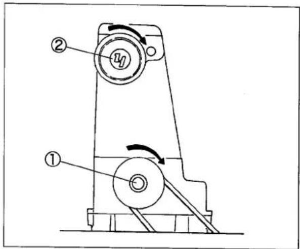
The rotating directions of the machine pulley ① and the handwheel ② are clockwise as shown in the figure.
CAUTION
If rotated in reverse direction, oil cannot be supplied properly. It can cause the damage to the machine.
| Model | Max. speed (rpm) | Standard speed (rpm) |
| CF2360 | 5500 | 5000 |
Table 1
text_image
Technical diagram of a mechanical device with labeled parts and directional arrows indicating motion or rotation.Fig. 1
2. Proper operation
2.1 Needle system

Sewing needle:
Groz-Beckert UY118GKS
Organ FL × 118GCS
Select the proper sewing needle in size depending on thickness and type of material.
Retainer needle:
One retainer needle is used with four sewing needles.
Groz-Beckert 36211, 36211A (with scarf)
Organ FLG-1, FLG-8 (with scarf)
Select the proper retainer needle in size depending on thickness and type of material.
| Japanese standard | 8 | 9 | 10 | 11 | 12 |
| Metric standard | 60 | 65 | 70 | 75 | 80 |
Table 2
Note: Some needles have not been sold in size. Check the size in a manufacturer's catalog.
| Japanese standard | 8 | 9 | 10 | 11 | 12 |
| Metric standard | 60 | 65 | 70 | 75 | 80 |
Table 3
Note: Some needles have not been sold in size. Check the size in a manufacturer's catalog.
2.2 Threading

When threaded, rethread after knotting preset threads.
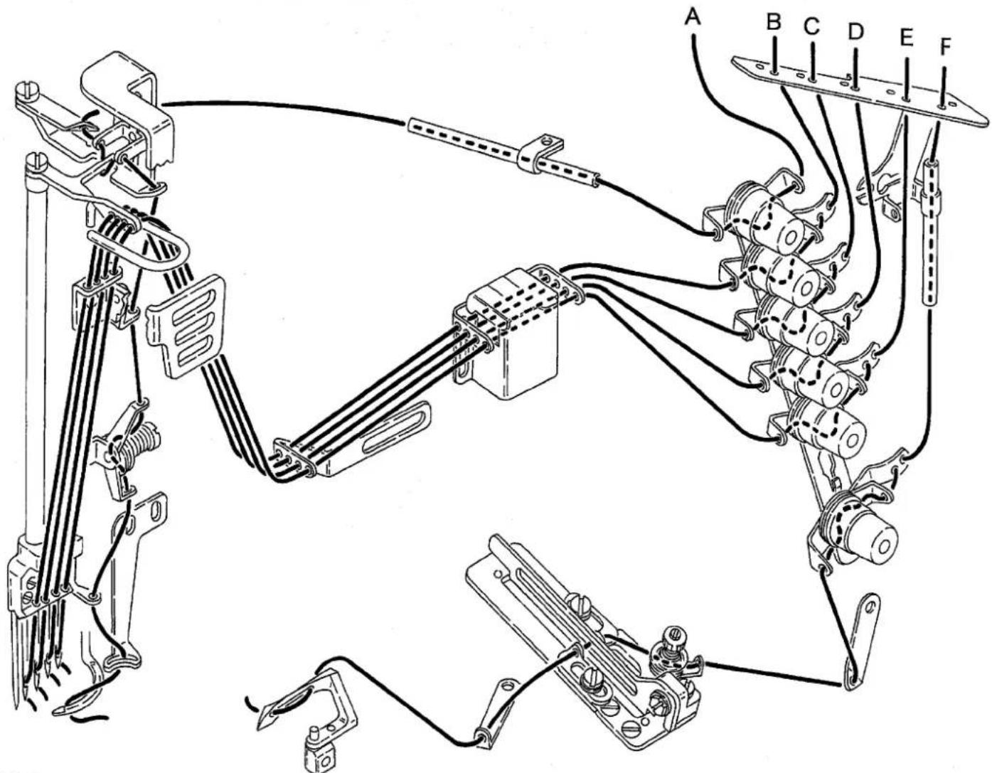
When not threaded, thread correctly as shown in Fig. 2.
Incorrect threading can cause skip stitch, thread breakage, or uneven seam.
A: Top cover thread
B,C,D,E: Needle thread
F: Looper thread
Needle thread
Pull out the thread until it is in front of the needles. Then, cut off the knots before needle eye to rethread.
Thread correctly for the left needle in the inmost position as shown in the figure.
Looper thread and Top cover thread
Pull the thread until the knot is out. Then, cut off the knot.
text_image
Technical diagram of a mechanical assembly with labeled components A through F, showing wiring and connections.Fig.2

WARNING
Before adjusting, ALWAYS turn the power switch OFF and check that the machine has already stopped.
3.1 Needle thread tension
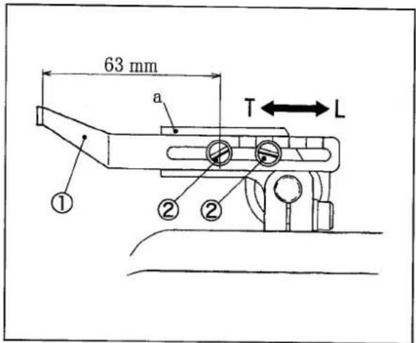
As standard, make the distance between the needle thread take-up① and the center of the left screw② to 63 mm, and set the part “a” horizontally when the needle bar is at the highest point.
Adjusting:
(1) Loosen the screws ②.
(2) Move the needle thread take-up ① to adjust it.
● To tighten the needle thread tension, move the needle thread take-up ① in the direction “T”.
● To loosen the needle thread tension, move the needle thread take-up ① in the direction “L”.
(3) Tighten the screws ② securely.
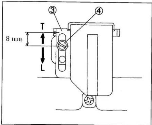
If not enough for adjusting above, move the needle thread eyelet ③ to adjust it.
Make the distance between the top of the needle thread eyelet and the center of the screw ④ to 8 mm as standard.
Adjusting:
(1) Loosen the screw ④.
(2) Move the needle thread eyelet ③ to adjust it.
● To tighten the needle thread tension, move the needle thread eyelet ③ in the direction “T”.
● To loosen the needle thread tension, move the needle thread eyelet ③ in the direction “L”.
(3) Tighten the screw ④ securely.
text_image
63 mm a T ← L ① ② ②Fig.3
text_image
8 mm T L ③ ④Fig. 4
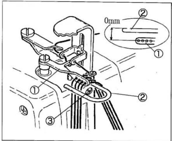
☆ Needle thread guide is used to stabilise forming the loop of needle thread.
As standard, the top of needle thread guide② is align the center of needle bar eyelet ① when the needle bar is at the lowest point.
Loosen the screw③ to adjust the hight and right-and-left position of the needle thread guide②.
text_image
0mm ① ② ③ ④Fig. 5
3.2 Top cover thread tension
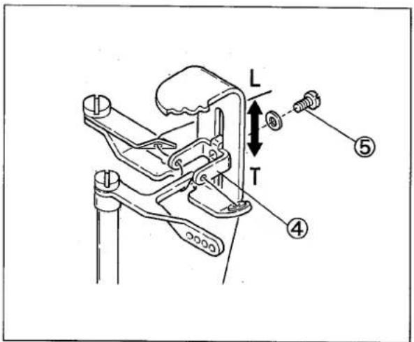
Loosen the screw ⑤ and move the top cover thread eyelet (upper) ④ to adjust it.
● To decrease take-up amount, move the top cover thread eyelet (upper)④ in the direction "T".
● To increase take-up amount, move the top cover thread eylet(upper)④ in the direction "L".
When using stretchable thread like woolly, move the top cover thread eyelet (upper)④ in the direction “L”.
text_image
L T ④ ⑤Fig. 6
3.3 Looper thread tension
Position of looper thread take-up
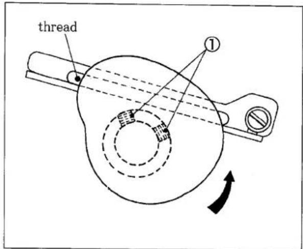
Fig. 7 shows the looper thread take-up seen from the needle bar side.
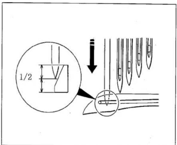
When the left needle lowers from the highest point and meets a half of the looper, the thread comes off from the top of the looper thread take-up. Loosen the screws ① to adjust it.
text_image
thread ①Fig. 7
text_image
1/2Fig. 8
3.4 Removing presser foot and presser foot lift
Removing presser foot
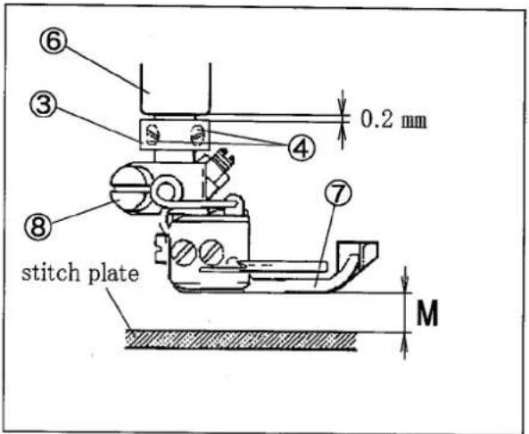
(1) Loosen the screws② of the lifter lever stop①, the screws ④ of the collar ③, and the screw ⑧ of the presser foot ⑦.
(2) Push down the lifter lever ⑤ to remove the presser foot ⑦.
Adjusting height of presser foot
(1) Push down the lifter lever⑤ to make the height from the top of the stitch plate to the bottom of the presser foot to the value of M in the Table 4.
(2) Tighten the screws ② securely.
(3) With keeping that, make the clearance between the end of the presser bar bushing⑥ and the top of the collar③ to 0.2 mm.
(4) Tighten the screws ④ securely.
After adjusting, push down the lifter lever ⑤ fully to check the height of the presser foot.
Presser foot lift depends on the needle distance.

text_image
Technical diagram of a mechanical device with numbered components and directional arrows indicating motion or assembly.Fig. 9
text_image
⑥ ③ ④ 0.2 mm ⑧ stitch plate ⑦ MFig.10
| Needle distance | Presser Foot height (M) (mm) |
| 5.6 | 4.5 |
| 6.4 | 4 |
Table 4
3.5 Looper
3.5.1 Installing angle and height of looper
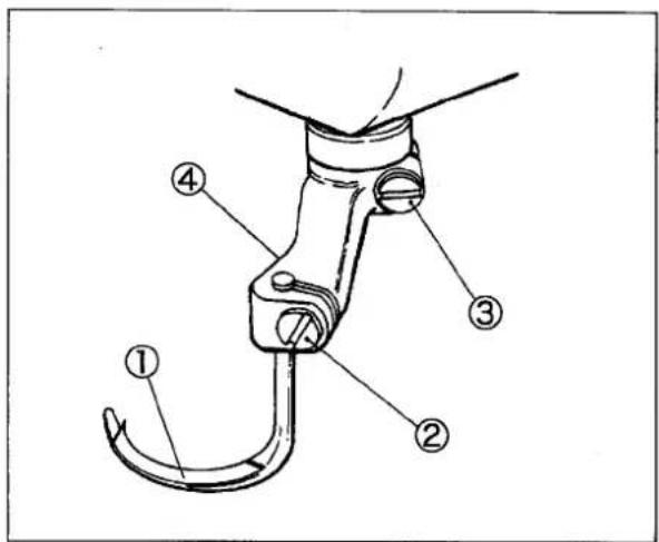
Insert the looper① into the looper holder② fully and tighten the screw ③ securely.
It makes the height and installing angle ( 0^ ).

text_image
Technical diagram of a mechanical assembly with numbered parts labeled ①, ②, and ③Fig. 11
3.5.2 Distance between looper and needle
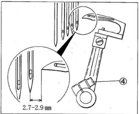
The distance between the looper tip and the center of the right needle is 2.7-2.9mm, when the needles are in the lowest points, and the looper ① is in the extreme right.
Loosen the screw ④ to adjust it.
NOTE
The distance between the center of the needle bar and the looper ① tip is 6.0 mm even if the needle distance changes.
text_image
2.7-2.9 mm ④Fig. 12
i Supplement
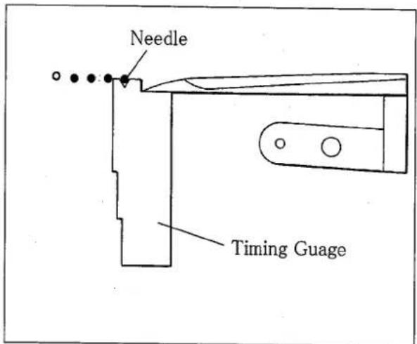
The timing gauge (No. 3200262) makes it possible to adjust the distance easily.
The gauge is an extra part. Place an order from our agents or directly from us.
3.5.3 Using timing gauge
Move the looper at the extreme right. Keep fitting the right needle into the groove "V" corresponding needle distance, and fit the looper tip to the gauge.
Then, tighten the screw ④ securely. (Fig. 12)
text_image
Needle Timing GuageFig. 13
3.6 Height of needle bar
Check points:
◇ Needles should be inserted fully into the needle holes of the needle clamp and fixed securely.
◇ Looper should be inserted fully into the looper holder and fixed securely.
Adjusting the height on the basis of looper:
(1) Install the needle to the left hole in the needle clamp.
(2) Check the looper is inserted into the looper holder fully.
(3) Turn the handwheel until the looper tip meets the center of the left needle.
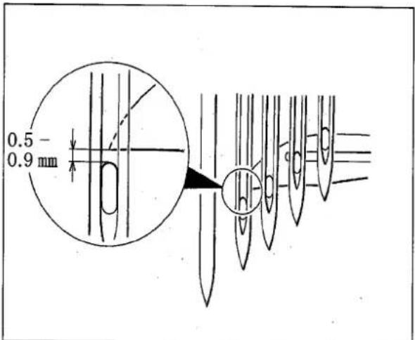
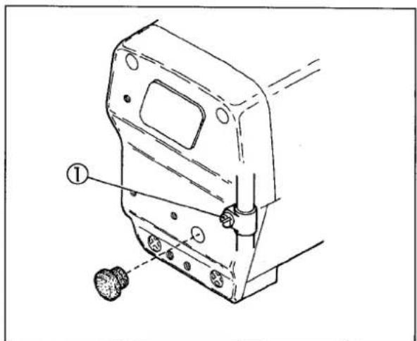
(4) Loosen the screw① of the needle bar bracket. Move the needle bar up or down so that the looper tip passes 0.5 - 0.9 mm above the top of the needle eye.
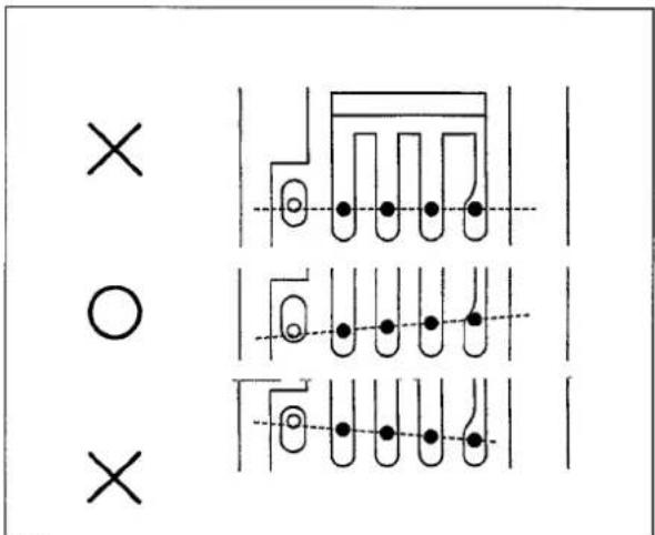
(5) Tighten the screw ① securely. Check that the needles drop in the centers of the needle holes of the stitch plate respectively.
text_image
× ○ ×Fig.15
text_image
0.5 0.9 mmFig. 14
text_image
Technical diagram of a mechanical component with numbered parts and annotation arrowsFig. 16
3. Adjustments
Adjusting the height from stitch plate
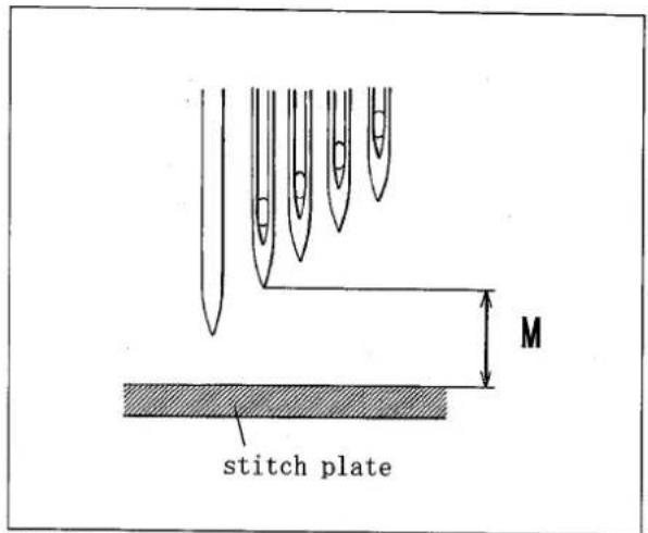
Adjusting the height from the surface of stitch plate with needle at the uppermost position, adjust the distance(M) from the fourth needle from the right to the height shown in the table below.
| Needle distance | UT | Mmm |
| 5.6 | × | 7.8 |
| ○ | 7.3 | |
| 6.4 | × | 6.8 |
| ○ | 6.3 |
Table 5
text_image
M stitch plateFig.17
3.7 Front-and-rear position of needle and looper
Longitudinal position of Needle and Looper
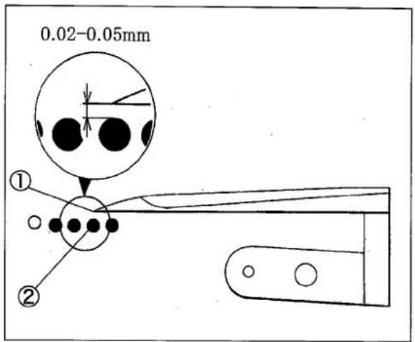
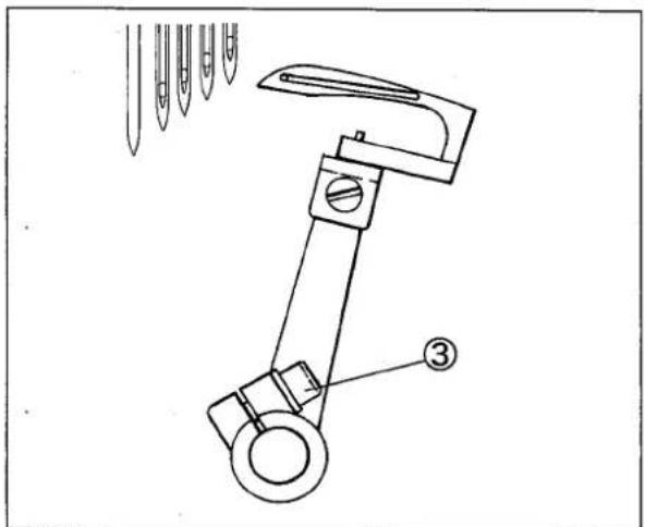
When the looper tip① meets the left needle②, the clearance between them must be 0.02-0.05mm. Loosen the screw③ to adjust it.
text_image
0.02-0.05mm ① ②Fig.18
text_image
Technical diagram of a mechanical device with labeled parts and directional arrows indicating motion or force vectors.Fig. 19
3.8 Needle and needle guard
3.8.1 Needle guard(rear)
Height:
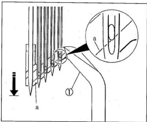
When the needle is at the lowest point, Align the line “a” on the needle guard(rear)① at the lower part of needle eye of the extreme right needle.(Fig. 21)
Front-and-rear position:
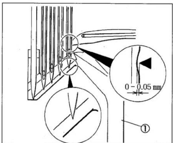
(1)When the looper tip meets the center of the extreme right needle, make the clearance between them to 0 - 0.05 mm to push the needle guard(rear)① to the right needle.(Fig. 22)
Make the clearance between the left needle and the needle guard(rear)① to 0.05 - 0.1 mm.
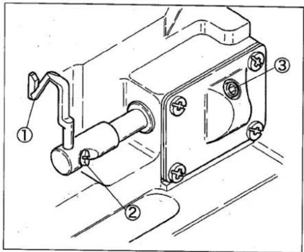
Loosen the screws ②③ to adjust them.
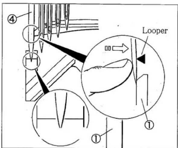
(2)While lightly pressing retaining needle④ against needle guard(rear)①, the looper tip must come in contact slightly with retaining needle when the looper tip passes.(Fig. 23)
text_image
Technical diagram of a mechanical assembly with numbered components, likely a valve or pump mechanism.Fig. 20
text_image
Technical diagram illustrating needle penetration and fiber optic cable installation with labeled components and directional arrowsFig. 21
text_image
0 - 0.05 mm ①Fig. 22
text_image
④ Looper ① ①Fig. 23
3.8.2 Needle guard(front)
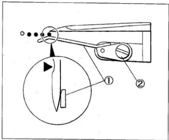
The clearance between needle and the needle guard(front)① makes it approach without coming in contact as much as possible.
Loosen the screw ② to adjust it.
NOTE
Adjust a clearance properly so as not to shift, if needle comes in contact too much with needle guard (front), looper tip hits needle, and needle shift widely left, when looper moves from the right to the left.
text_image
Technical diagram of a sewing machine with labeled parts and a magnified circular detail viewFig. 24
3.9 Needle and spreader
Spreader
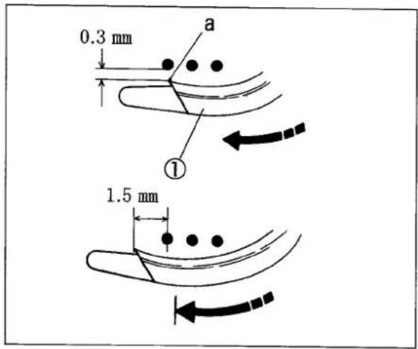
Make the clearance between the left needle and the hook "a" to 0.3 mm when the spreader① moves from the right to the left.
Make the clearance between the center of the left needle and the hook "a" to 1.5 mm when the spreader moves at extreme left.
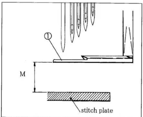
Make the height from the top of the stitch palte to the bottom of the spreader ① to value M of Table 5.
Loosen the screw② of the spreader and the screw③ of the spreader holder ④ to adjust it.
NOTE
Adjust the height of the spreader so that the top cover thread passes behind the right needle and be caught by the left needle within adjustable range based on the needle distance.
| Needle distance | UT | Mmm |
| 5.6 | × | 6.7 |
| ○ | 6.2 | |
| 6.4 | × | 6.2 |
| ○ | 5.7 |
Table 6
text_image
0.3 mm a ① 1.5 mmFig. 25
text_image
M ① stitch plateFig.26
text_image
Technical diagram of a hook mechanism with numbered parts labeled ① to ④Fig.27
| Model | CF2360 |
| Description | High speed flat bed 4-needle interlock stitch machine |
| Dimensions | 500 (L) × 250 (W) × 430 (H) mm |
| Weight | 41 kg |
| Stitch Type | ISO 607 |
| Application | Covering for knitted fabric |
| Sewing Speed | During intermittent operation |
| Up to 5500 rpm | |
| Stitch Length | 1.4 - 3.6 mmThe number of stitches 7 - 18 stitches per inch (25.4 mm)8 - 21 stitches per 30 mm |
| Needle system | Sewing needle:FLX118GCS(organ) or UY118GKS(Shumetz) #65 - #80Retaining needle:FLG-1, FLG-8(organ) or 36211, 36211A(Shumetz) |
| Needle Distance | 5.6, 6.4 mm |
| Needle Stroke | 26 mm |
| Presser Foot Lift | 4.0 mm (needle distance: 6.4 mm) - 4.5 mm (5.6 mm) |
| Feed Regulation | Push button system |
| Differential Ratio | 1:0.7 - 1:2 |
| Differential Feed Regulation | External lever even during operation |
| Lubrication | Lubrication automatically by pump |
| Lubricating Oil | YAMATO SF OIL #28 |
| Capacity of Oil Reservoir | 1100 cc |
| Installation | Semi-submerged type |
Table 7
1jamato
YAMATO SEWING MACHINE
YAMATO SEWING MACHINE (NIMGBO) CO., LTD.
No.641, WEST HENGSHAN ROAD, ECONOMIC
& TECHNICAL DEVELOPMENT ZONE, BEILUN.
NINGBO, P.R.CHINA, P.C. 315800
Tel. +86-574-8680-0888
Fax. +86-574-8680-0555