
APA4200G - Autoradio CLARION - Kostenlose Bedienungsanleitung
Finden Sie kostenlos die Bedienungsanleitung des Geräts APA4200G CLARION als PDF.


| Produkttyp | Autoradioverstärker |
| Marke | Clarion |
| Modell | APA4200G |
| Kanäle | 4-Kanal |
| Nennleistung (4-Kanal-Modus) | 50 W × 4 (RMS, 4 Ω, 0,02 % THD) |
| Nennleistung (3-Kanal-Modus) | 35 W × 2 + 110 W × 1 |
| Nennleistung (2-Kanal-Modus) | 100 W × 2 |
| Maximale Ausgangsleistung | 90 W × 4 |
| Frequenzgang | 10 Hz – 50.000 Hz |
| Klirrfaktor (THD) | 0,02 % |
| Signal-Rausch-Abstand (S/N) | 115 dB |
| Eingangsempfindlichkeit | 200 mV – 5.000 mV |
| Hochpass-/Tiefpassfilter | 50 Hz – 200 Hz, -24 dB/Oktave |
| Bass Extender | +1 dB bis +12 dB bei 50 Hz |
| Betriebsspannung | 14,4 V (Minuspol geerdet) |
| Stromverbrauch (Nennleistung) | 28 A |
| Stromverbrauch (ohne Signal) | 1,1 A |
| Sicherung | 30 A × 1 |
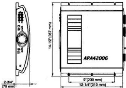
| Abmessungen (B × H × T) | 367 mm × 70 mm × 310 mm |
| Gewicht | 5,4 kg |
| Schutzschaltungen | Überstrom-, Überhitzungs- und Kurzschlussschutz |
| Power Guard-Schaltung | Schaltbar (ein/aus) zur Vermeidung von Verzerrungen |
| Anschlüsse | Vergoldete RCA-Eingänge und Lautsprecherklemmen |
| Kühlung | Passiv (Kühlkörper) |
| Einbaulage | Belüfteter Ort, starre Oberfläche |
Häufig gestellte Fragen - APA4200G CLARION
Benutzerfragen zu APA4200G CLARION
0 Frage zu diesem Gerät. Beantworten Sie die, die Sie kennen, oder stellen Sie Ihre eigene.
Eine neue Frage zu diesem Gerät stellen
Laden Sie die Anleitung für Ihr Autoradio kostenlos im PDF-Format! Finden Sie Ihr Handbuch APA4200G - CLARION und nehmen Sie Ihr elektronisches Gerät wieder in die Hand. Auf dieser Seite sind alle Dokumente veröffentlicht, die für die Verwendung Ihres Geräts notwendig sind. APA4200G von der Marke CLARION.
BEDIENUNGSANLEITUNG APA4200G CLARION
clarion
APA4400G 100W × 4 channel power amplifier
APA4200G 50W × 4 channel power amplifier
OPERATION AND INSTALLATION MANUAL
-1. INTRODUCTION
Built-In Strong Power Supply
A stable power is supplied even at the instant change of signals through lowering impedance achieved thoroughly by the adoption of PWM DC-DC converter supported by high performance and low loss power MOS-FET, a group of parts with large capacities, low impedance capacitors and toroidal coils and by the further adoption of thick foil substrate (*bus bar), etc. (*APA4400G)
Design emphasizing sound quality
Adopting a low-noise, high slew rate operational amplifier, power amplification element with good current linearity, and through-relays that pass complicated signal lines, this unit has been designed with much consideration of sound quality. Diversified Functions
The preoutput terminal for external amplifier expansion, high-pass/low-pass filter that varies the cut-off frequency from 50 Hz to 200 Hz, and etc., allows full-scale system grade-up of a multi-amplifier, multi-speaker.
Power Guard Circuit
When the amp is in overdrive, this circuit detects any distortion and automatically holds down the input gain to prevent unpleasant clipping distortion. The power guard circuit can be switched on/off with the selector switch.
High definition: power guard on
High current: power guard off
* The power guard circuit is patented by the McIntosh Laboratories of the U.S.A. Built-in Protection Circuit
This circuit protects against damage to the amplifier from overcurrent and overheat caused by an excessive power voltage and short-circuit when overloading.
A channel mode selector switch provides the following high output (rated):
APA4400G
• 4-channel mode ... 100W × 4
• 3-channel mode ... 70W × 2 + 260W × 1
• 2-channel mode ... 200W × 2
APA4200G
- 4-channel mode ... 50W × 4
- 3-channel mode ... 35W × 2 + 110W × 1
• 2-channel mode ... 100W × 2
Protection Circuit
A protection circuit is used to constantly protect against damage to the amplifier from loads, short-circuits, overcurrents, overheating, etc.
Low-heat Design
Reduced power supply circuit heat loss and a large fan (APA4400G) with a high cooling efficiency structure reduce the heat generated during operation.
-2. DESCRIPTION
APA4400G
natural_image
Line drawing of a device casing with ventilation slots and a button (no text or symbols)APA4200G
natural_image
Line drawing of a device casing with ventilation slots and a circular component (no text or symbols)Figure 1 Clarion APA4400G/APA4200G 4-Channel Car Audio Amplifier
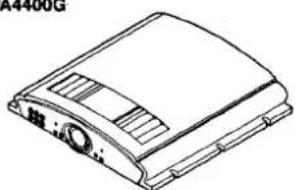
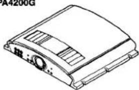
The Clarion APA4400G/APA4200G car audio amplifier (shown in Figure 1) is a 4 channel amplifier that delivers 100 watt × 4 or 50 watt × 4 (RMS), respectively, into a 4 ohm load. Depending on your application, one or more amplifiers is an excellent choice for customizing your own car audio system.
All connections and controls are on end panels and are straightforward and easy to understand.
We use gold-plated RCA and barrier connectors to ensure the best electrical connection for your system. Included are external automotive-type fuses that are easy to replace.
3. Amplifier Controls and Power Indicator Connections
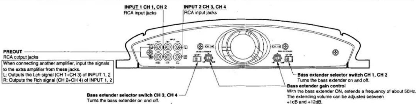
Figure 2 Front Panel Layout of the Clarion APA4400G/APA4200G 4-Channel Car Audio Amplifier
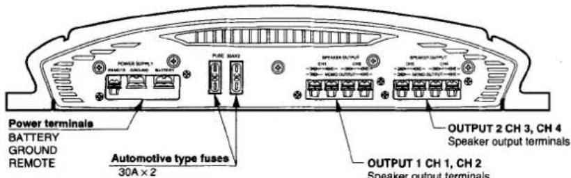
Figure 3 Rear Panel Layout of the Clarion APA4400G 4-Channel Car Audio Amplifier
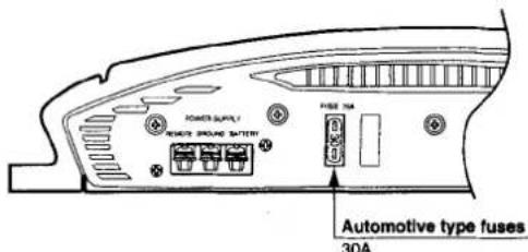
Figure 4 Rear Panel Layout of the Clarion APA4200G 4-Channel Car Audio Amplifier
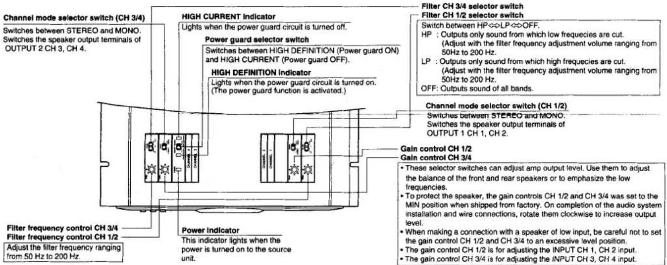
Figure 5 Upper Panel Layout of the Clarion APA4400G/APA4200G 4-Channel Car Audio Amplifier
4.
CONNECTIONS
- The rear panel of the APA4400G/APA4200G holds the external fuse as well as connections for power, speakers, as shown in Figure 3.
-
On the APA4400G/APA4200G, the gold-plated power terminals are labeled (left to right) as REMOTE (remote turn-on), GROUND and BATTERY.
-
The speaker terminals are also gold-plated.
- The INPUT and PREOUT connectors on the APA4400G/APA4200G are gold-plated RCA jacks, marked [L] for the Left channel and [R] for the Right channel.
5.
APPLICATIONS
flowchart
graph TD
    A["Source unit (DRX9255)"] --> B["APA4400G"]
    B --> C["SRS1691 Front Speaker"]
    B --> D["SRS1691 Rear Speaker"]
    B --> E["APA4200G"]
    E --> F["SRM2591 Subwoofer"]
    E --> G["SRM2591 Subwoofer"]
    B --> H["Main power cord connection"]
    E --> I["Main power cord connection"]
    B --> J["Ground cord connection"]
    E --> K["Ground cord connection"]
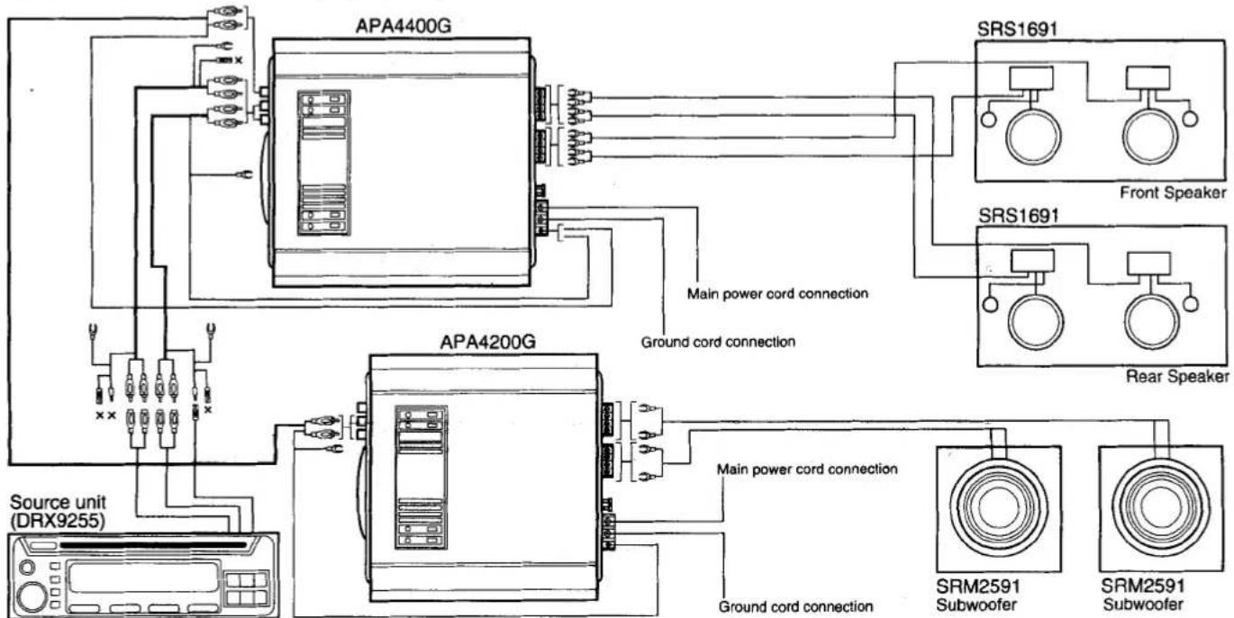
Figure 6 Overall Connections
The Clarion APA4400G/APA4200G 4-channel car audio amplifier can be used in a variety of system applications. We have presented connection examples for an audio system that will help you design your own audio system.
Note: Before switching the channel mode and low-pass filter selector switches, turn the power of the source unit off.
4-Channel Mode
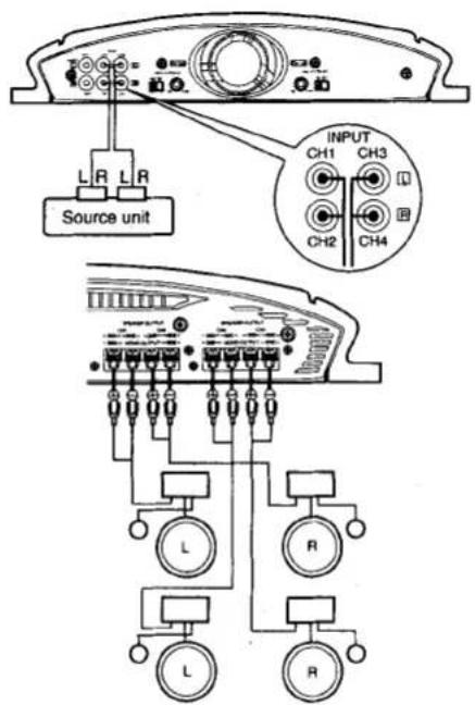
Figure 7 4-Channel Mode
3-Channel Mode
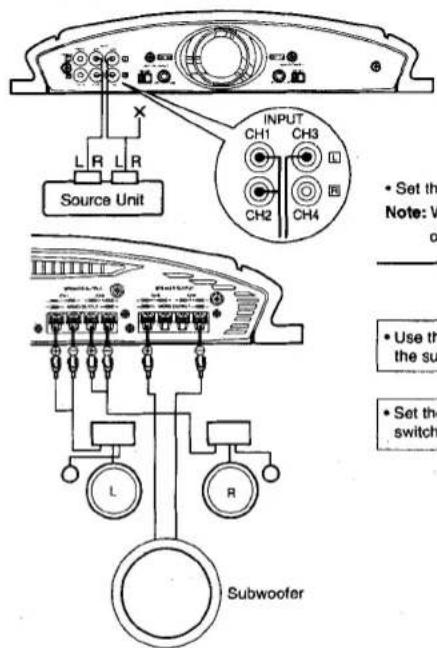
- Set the filter selector switch and the channel mode selector switch. Note: When setting these selector switches, be sure to turn off the power of the source unit.
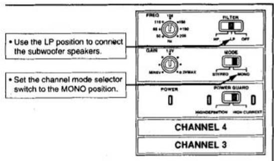
Figure 8 3-Channel Mode
2-Channel Mode
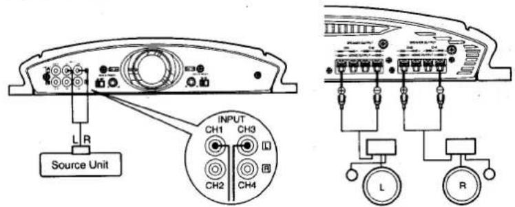
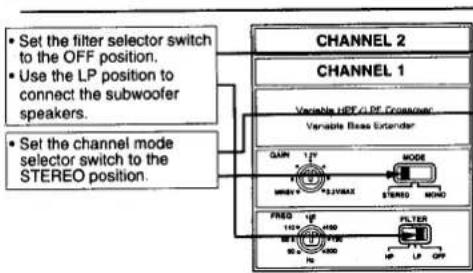
- Set the filter selector switch and the channel mode selector switch.
Note: When setting these selectors switches, be sure to turn off the power of the source unit.
flowchart
graph TD
    A["Set the filter selector switch to the OFF position.<br>Use the LP position to connect the subwoofer speakers."] --> B["Channel 2"]
    C["Set the channel mode selector switch to the STEREO position."] --> B
    B --> D["CHANNEL 1"]
    D --> E["Variable HDF CL PF Controller"]
    D --> F["Variable Bass Extender"]
    E --> G["MODE"]
    F --> H["STEREO"]
    G --> I["FRED"]
    H --> J["FILTER"]
    I --> K["HP"]
    J --> L["LP"]
    K --> M["QFP"]
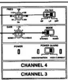
Figure 9 2-Channel Mode
Connecting the PREOUT RCA Output Jacks
This amplifier (APA4400G/APA4200G)
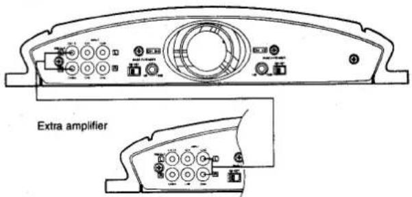
Figure 10 Connecting The PREOUT RCA Output Jacks
When connecting another amplifier, input the signals to the extra amplifier's INPUT RCA jacks from the APA4400G/APA4200G's PREOUT RCA output jacks.
The signals from the APA4400G/APA4200G's INPUT 1 jacks are output from these jacks.
6. INSTALLATION
The section lists mounting and wiring precautions for installing the Clarion APA4400G/APA4200G car audio amplifier. Combined with the experience of a professional installer, these safeguards are sufficiently detailed to successfully complete installation. If you do not have the necessary skills, do not install the amplifier yourself. Instead, see your authorized Clarion dealer for installation recommendations.
Mounting Precautions
Although this Clarion amplifier incorporates a large heat sink and multi level protection circuits, mounting any amplifier in a confined space without any air movement can still damage internal circuits over time. Choose a site that provides adequate ventilation around the amplifier. For easy system set-up, mount the amplifier so the controls and fuse will be accessible after installation.
In addition, observe these precautions:
- For the most efficient cooling, mount the amplifier so cool air runs along the length of the fins rather than across them. Remember, any moving air will dissipate heat.
- Mount the amplifier on a rigid surface. Do not install the amplifier on plastic or other combustible material.
- Prior to drilling, make sure proposed mounting holes will not cut into the fuel tank, fuel lines, brake lines (under chassis), or electrical wiring.
Cautions on installation
- Be sure to use the screws supplied with this amplifier to install it in your car. Mounting the amplifier using screws other than those supplied may lead to malfunctioning of the unit.
- When you mount the amplifier, be careful not to damage the wiring in your car with tools or parts such as tapping screws.
Installation procedure
- Open six holes (ø3.5 mm) to mount the unit.
- Use the six tapping screws (5 × 30) to secure the unit. (APA4400G) [For fixing the APA4200G, use the four tapping screw (5 × 30).]
- When mounting the unit on a plastic plate or carpet, use the plate nuts.
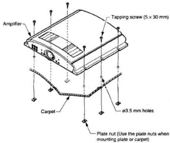
Figure 11 Installation Procedure
Wiring Precautions
- Read all wiring precautions. If you are not sure of the connections, contact your authorized Clarion dealer.
- Before installation, make sure the source unit power switch is turned OFF.
- Disconnect the negative (-) lead at the battery before making any power connections.
- When making connections, be sure that each connection is clean and secure. Insulate final connections with electrical tape or shrink tubing. Failure to do so may damage your equipment.
- A secure, clean ground connection is critical to the performance of your Clarion car audio amplifier. Use the shortest ground wire possible to minimize resistance and avoid noise problems.
- Add an external fuse on the positive (+) power lead and connect it as close as possible to the vehicle's (+) battery terminal. Use a rating that equals the total current consumption at full output of all amplifiers in the system. Adding an external fuse will protect the electrical system from short-circuits that can cause fire.
- Refer to Figure 12 when making electrical connections. Connect the amplifier's positive (+) power lead via a fuse directly to the positive (+) terminal on the car battery. Do not connect this wire to the car's fuse panel. Use the yellow-insulated 8 gauge (for APA4400G) or 10 gauge (for APA4200G) (or longer) wire for the amplifier's positive (+) power lead and the same gauge black insulated wire for the ground.
- A ring terminal cannot be used for the speaker output terminal of the APA4400G and the APA4200G, and for the power source terminal of the APA4200G. (The terminal screw has been designed not to come off.)
- When replacing an amplifier's fuse, always use one having the same current rating. Substituting with a higher-rated fuse can reduce protection and may result in serious damage to the amplifier.
- Never ground the speakers to the vehicle chassis or body.
- Make sure that your vehicle's electrical system (i.e., alternator, battery, etc.) is capable of handling the additional load. If you are planning to install a multi-amplifier system, you may need to add a second battery and possibly upgrade the alternator with a higher-output-rated model. Consult your Clarion dealer for recommendations.
- To avoid possible noise problems, run the amplifier's positive (+) power lead along one side of the vehicle to the battery. Run the remote turn-on wire and RCA audio cable down the center, and route the speaker wires along the remaining side. If wires must cross, run the perpendicular to each other.
- When creating passage holes for the power wire, use grommets to eliminate any sharp edges created during drilling. This will protect the wire from being nicked and causing a short-circuit.
- Extra cable causes signal loss and acts as an "antenna" for noise. Use only high quality RCA cables that are no longer than necessary to make a direct connection with the source unit or equalizer.
- Depending on the type of system being installed, refer to the examples in Figures 4 through 9 for information on wiring and setting the operation mode.
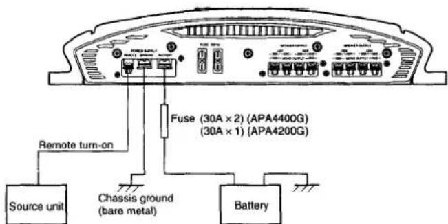
Figure 12 Electrical Connections for the APA4400G/APA4200G Car Audio Amplifier
7. FINAL SYSTEM CHECKS
-
Start the engine and turn on the source unit. After a short two-second delay, slowly raise the volume and listen to the sound. If you hear any noise, static, distortion, or no sound at all, check the connections, and also refer to the "Troubleshooting" section. Depending on your system design, the levels may become quite loud even a low volume control settings. Until you get a "feel" of the power of the system, use care when adjusting the controls.
-
Adjust the balance control from left to right and listen to the results. Audio imaging should match control settings.
-
TROUBLESHOOTING
| Symptom | Cause | Solution |
| No audio | Low or no remote turn-on voltageBlown fusePower wires not connectedSpeakers not connected or blown | Check remote connections at amplifier and source unit.Replace with new fast-blow fuse (same rating).Check power and ground connections at amplifier; check battery connections.Check speaker connectors at amplifier; measure coil impedance. |
| Audio cycles on and off | Thermal protection circuits are shutting amplifier off. | Check location for adequate ventilation; consult an authorized Clarion dealer. |
| Distorted sound | Gain control is not set properly, or damaged speaker cones | Adjust gain control; check each speaker cone for signs of damage (e.g., frozen cone, burning smell, etc.). |
| Whining or ticking noise in the sound with engine on | Amplifier is picking up alternator noise or radiated noise | Check power and ground connections on amplifier; check or move audio cables; install an in-line noise filter on source unit's power wire; check alternator and/or voltage regulator; test for weak battery or add water to battery. |
- SPECIFICATIONS
| APA4400G | |
| Maximum Output : | 175W × 4 |
| Rated Output : | 100W × 4 (4-channel mode)(20Hz ~ 20kHz, 0.02%, 4Ω, with 4-channelsimultaneous output)70W × 2 + 260W × 1 (3-channel mode)200W × 2 (2-channel mode) |
| Frequency Response : | 10 ~ 50,000Hz |
| Harmonic Distortion : | 0.02% (20Hz ~ 20kHz, 4-channel mode, 100W × 4simultaneous output) |
| S/N Ratio : | 118dB |
| Applicable Speaker Impedance: | 4Ω (2Ω ~ 8Ω, channel mode: Stereo) |
| Input Sensitivity : | 200mV ~ 5,000mV |
| Low-Pass Filter/High-Pass | |
| Filter Cut-off Frequency : | 50Hz ~ 200Hz, (-24dB/oct) |
| Bass Extender : | +1dB ~ +12dB (at 50 Hz) |
| Power Source Voltage : | 14.4V |
| Ground : | Negative |
| Power Consumption : | 56A (with 100W × 4 rated output)1.8A (amplifier ON, no input) |
| Auto-fuse capacity : | 30A × 2 |
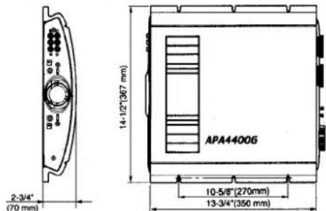
| External dimensions : | 14-1/2"(367mm) Width × 2-3/4"(70mm) Height ×13-3/4"(350mm) Depht |
| Weight : | 15.43 lb. (7 kg) |
* For improvement purposes, specifications and design are subject to change without prior notice.
| APA4200G | |
| Maximum Output : | 90W × 4 |
| Rated Output : | 50W × 4 (4-channel mode)(20Hz ~ 20kHz, 0.02%, 4Ω, with 4-channelsimultaneous output)35W × 2 + 110W × 1 (3-channel mode)100W × 2 (2-channel mode) |
| Frequency Response : | 10 ~ 50,000Hz |
| Harmonic Distortion : | 0.02% (20Hz ~ 20kHz, 4-channel mode, 50W × 4simultaneous output) |
| S/N Ratio : | 115dB |
| Applicable Speaker Impedance: | 4Ω (2Ω ~ 8Ω, channel mode: Stereo) |
| Input Sensitivity : | 200mV ~ 5,000mV |
| Low-Pass Filter/High-Pass | |
| Filter Cut-off Frequency : | 50Hz ~ 200Hz, (-24dB/oct) |
| Bass Extender : | +1dB ~ +12dB (at 50 Hz) |
| Power Source Voltage : | 14.4V |
| Ground : | Negative |
| Power Consumption : | 28A (with 50W × 4 rated output)1.1A (amplifier ON, no input) |
| Auto-fuse capacity : | 30A × 1 |
| External dimensions : | 14-1/2"(367mm) Width × 2-3/4"(70mm) Height ×12-1/4"(310mm) Depht |
| Weight : | 11.9 lb. (5.4 kg) |
* For improvement purposes, specifications and design are subject to change without prior notice.

- clarion
- APA4400G 100W × 4 channel power amplifier
- APA4200G 50W × 4 channel power amplifier
- -1. INTRODUCTION
- Built-In Strong Power Supply
- Design emphasizing sound quality
- Power Guard Circuit
- APA4400G
- APA4200G
- Protection Circuit
- Low-heat Design
- -2. DESCRIPTION
- Amplifier Controls and Power Indicator Connections
- 4.
- CONNECTIONS
- 5.
- APPLICATIONS
- INSTALLATION
- Mounting Precautions
- In addition, observe these precautions:
- Cautions on installation
- Installation procedure
- Wiring Precautions
- FINAL SYSTEM CHECKS
Marke : CLARION
Modell : APA4200G
Kategorie : Autoradio